US6543652B1 - Closure with dispensing valve - Google Patents
Closure with dispensing valveDownload PDFInfo
- Publication number
- US6543652B1 US6543652B1US09/980,459US98045902AUS6543652B1US 6543652 B1US6543652 B1US 6543652B1US 98045902 AUS98045902 AUS 98045902AUS 6543652 B1US6543652 B1US 6543652B1
- Authority
- US
- United States
- Prior art keywords
- cover
- valve
- dispensing
- container
- closure
- Prior art date
- Legal status (The legal status is an assumption and is not a legal conclusion. Google has not performed a legal analysis and makes no representation as to the accuracy of the status listed.)
- Expired - Fee Related
Links
Images


Classifications
- B—PERFORMING OPERATIONS; TRANSPORTING
- B65—CONVEYING; PACKING; STORING; HANDLING THIN OR FILAMENTARY MATERIAL
- B65D—CONTAINERS FOR STORAGE OR TRANSPORT OF ARTICLES OR MATERIALS, e.g. BAGS, BARRELS, BOTTLES, BOXES, CANS, CARTONS, CRATES, DRUMS, JARS, TANKS, HOPPERS, FORWARDING CONTAINERS; ACCESSORIES, CLOSURES, OR FITTINGS THEREFOR; PACKAGING ELEMENTS; PACKAGES
- B65D47/00—Closures with filling and discharging, or with discharging, devices
- B65D47/04—Closures with discharging devices other than pumps
- B65D47/20—Closures with discharging devices other than pumps comprising hand-operated members for controlling discharge
- B65D47/24—Closures with discharging devices other than pumps comprising hand-operated members for controlling discharge with poppet valves or lift valves, i.e. valves opening or closing a passageway by a relative motion substantially perpendicular to the plane of the seat
- B65D47/241—Closures with discharging devices other than pumps comprising hand-operated members for controlling discharge with poppet valves or lift valves, i.e. valves opening or closing a passageway by a relative motion substantially perpendicular to the plane of the seat the valve being opened or closed by actuating a cap-like element
- B65D47/242—Closures with discharging devices other than pumps comprising hand-operated members for controlling discharge with poppet valves or lift valves, i.e. valves opening or closing a passageway by a relative motion substantially perpendicular to the plane of the seat the valve being opened or closed by actuating a cap-like element moving helically
- B—PERFORMING OPERATIONS; TRANSPORTING
- B65—CONVEYING; PACKING; STORING; HANDLING THIN OR FILAMENTARY MATERIAL
- B65D—CONTAINERS FOR STORAGE OR TRANSPORT OF ARTICLES OR MATERIALS, e.g. BAGS, BARRELS, BOTTLES, BOXES, CANS, CARTONS, CRATES, DRUMS, JARS, TANKS, HOPPERS, FORWARDING CONTAINERS; ACCESSORIES, CLOSURES, OR FITTINGS THEREFOR; PACKAGING ELEMENTS; PACKAGES
- B65D47/00—Closures with filling and discharging, or with discharging, devices
- B65D47/04—Closures with discharging devices other than pumps
- B65D47/20—Closures with discharging devices other than pumps comprising hand-operated members for controlling discharge
- B65D47/2018—Closures with discharging devices other than pumps comprising hand-operated members for controlling discharge comprising a valve or like element which is opened or closed by deformation of the container or closure
- B65D47/2031—Closures with discharging devices other than pumps comprising hand-operated members for controlling discharge comprising a valve or like element which is opened or closed by deformation of the container or closure the element being formed by a slit, narrow opening or constrictable spout, the size of the outlet passage being able to be varied by increasing or decreasing the pressure
- B65D47/2037—Closures with discharging devices other than pumps comprising hand-operated members for controlling discharge comprising a valve or like element which is opened or closed by deformation of the container or closure the element being formed by a slit, narrow opening or constrictable spout, the size of the outlet passage being able to be varied by increasing or decreasing the pressure the element being opened or closed by actuating a separate element which causes the deformation, e.g. screw cap closing container slit
- B—PERFORMING OPERATIONS; TRANSPORTING
- B65—CONVEYING; PACKING; STORING; HANDLING THIN OR FILAMENTARY MATERIAL
- B65D—CONTAINERS FOR STORAGE OR TRANSPORT OF ARTICLES OR MATERIALS, e.g. BAGS, BARRELS, BOTTLES, BOXES, CANS, CARTONS, CRATES, DRUMS, JARS, TANKS, HOPPERS, FORWARDING CONTAINERS; ACCESSORIES, CLOSURES, OR FITTINGS THEREFOR; PACKAGING ELEMENTS; PACKAGES
- B65D47/00—Closures with filling and discharging, or with discharging, devices
- B65D47/04—Closures with discharging devices other than pumps
- B65D47/20—Closures with discharging devices other than pumps comprising hand-operated members for controlling discharge
- B65D47/24—Closures with discharging devices other than pumps comprising hand-operated members for controlling discharge with poppet valves or lift valves, i.e. valves opening or closing a passageway by a relative motion substantially perpendicular to the plane of the seat
- B65D47/241—Closures with discharging devices other than pumps comprising hand-operated members for controlling discharge with poppet valves or lift valves, i.e. valves opening or closing a passageway by a relative motion substantially perpendicular to the plane of the seat the valve being opened or closed by actuating a cap-like element
- B65D47/243—Closures with discharging devices other than pumps comprising hand-operated members for controlling discharge with poppet valves or lift valves, i.e. valves opening or closing a passageway by a relative motion substantially perpendicular to the plane of the seat the valve being opened or closed by actuating a cap-like element moving linearly, i.e. without rotational motion
Definitions
- the present inventionrelates to dispensing closures incorporating a self-closing valve, for use with squeeze-type containers, such as flexible bottles or tubes.
- the valveis adapted to open when the container is squeezed, to allow product to be dispensed and thereafter, once the container is released, the valve closes automatically.
- the inventionrelates to dispensing closures of this type which include a built-in seal to seal the valve and prevent accidental spillage of the contents of the container during transportation or storage.
- Dispensing closures incorporating a self-closing valveare becoming more popular as after first opening by a user, the container may be stored and used without the need to open and close a separate lid.
- the valveensures that the contents of the container will not leak even when the container is inverted.
- Such closuresare therefore ideal for use with personal care products, such as shampoo and shower gel or foodstuffs, such as tomato ketchup and sauces.
- a typical closureincludes a flexible, self-closing valve arranged to cover the opening in a container.
- the valveis provided with one or more slits which define a normally closed orifice.
- a common form of self-closing valvehas two slits in a cross configuration to define four flaps, which are normally closed. When the container is squeezed, the flaps open to provide an orifice through which the contents of the container may be dispensed.
- a typical dispensing closure incorporating a self-sealing valvecomprises a body, arranged to co-operate with a container neck, the body defining a seat for the self-closing valve.
- the valveis held in place in the seat by a clip or retaining ring.
- the closuremay also be provided with a lid to cover the valve during transportation and storage. The lid ensures that the valve remains clean and is not damaged before it reaches the consumer.
- Many closure designsincorporate a hinged lid, which is produced integrally with the body. Sometimes, the lid is provided with a projection, which is sized and arranged to co-operate with the closed valve and prevent it from opening when the lid is closed. This arrangement ensures that the contents of the container are not accidentally dispensed into the cavity between the closure body and the lid.
- the proposed closurecomprises a body, adapted to co-operate with a container opening, and a housing, which can be raised and lowered relative to the body using either a twisting or push-pull movement.
- the housingprovides a seat for the dispensing valve, as in the conventional closures previously discussed, but also has a sealing plug located below the level of the valve, between the valve and the container opening.
- the closure bodyprovides a sealing ring around the container opening.
- the sealing plug in the housingforms a seal with the sealing ring in the closure body, when the housing is in its lowered position, preventing leakage of the container contents.
- the valveis sealed inside the closure rather than by means of an external cover or lid.
- the sealing plug and sealing ring arrangementensures that the container contents are prevented from coming into contact with the valve during transportation and storage of the package.
- the applicantshave found that a much simpler sealing arrangement can be provided inside the closure, in the dispensing passageway, requiring fewer components and less accurate alignment.
- the closure according to the inventionis therefore, simpler and easier to manufacture and assemble than the closure proposed in WO97/22520.
- the present inventionprovides a simplified closure having a dispensing valve and a transport/storage seal inside the closure within the dispensing passageway.
- the transport/storage sealis arranged so that the container/closure package can be sealed or unsealed by either twisting or push-pull movement of the outside of the closure by the user.
- the present inventionprovides a closure for a container opening, the closure comprising a housing, adapted to co-operate with the container opening and defining a dispensing passageway; a cover disposed on the housing for movement between lowered and raised positions relative to the housing; and a flexible dispensing valve, characterised in that the housing provides a sealing plate located, in use, between the dispensing valve and the container opening; the sealing plate adapted to partially occlude the container opening and defining at least one dispensing aperture; and the dispensing valve is arranged to seal the or all of the dispensing apertures when the cover is in its lowered position.
- the dispensing valveis used to provide the “sealing plug” to block the dispensing apertures in the sealing plate during transportation and storage of the package.
- a separate sealing plugis not required, simplifying the design.
- due to the flexibility of the valveit is able to conform to the contour of the dispensing aperture/s and therefore forms a good seal.
- valve and sealing plateare arranged in fixed orientation relative to one another within the housing and the housing is fixed in relation to the container opening. This arrangement has the advantage that a moving seal is not required between the cover and the housing.
- the coveris adapted to press against part of the valve as the cover is lowered. This stretches part of the valve, so that it blocks the dispensing aperture or apertures and the lowered cover holds the stretched portion of the valve in place to ensure that the seal is retained.
- the coveris raised, the natural elasticity of the valve material returns the valve to its original relaxed configuration and the contents of the container are able to pass through the dispensing apertures.
- an annular projectionis provided on the internal surface of the cover. The projection is arranged to co-operate with the periphery of the dispensing valve and thereby stretch this portion of the valve.
- the dispensing aperturesare arranged around the periphery of the sealing plate such that they are sealed by the stretched portion of the dispensing valve when the cover is in its lowered position.
- the valvemay be retained in a seat in the housing by a retaining ring or clip, as in the conventional dispensing valve closures.
- a retaining ring or clipas in the conventional dispensing valve closures.
- the annular projection from the covermay be configured to ensure that the valve is retained in the seat when the cover is in its raised and lowered positions. This arrangement removes the need for a separate retaining ring or clip and thereby further simplifies the design and assembly of the closure.
- the covermay be adapted to press part of the valve against the dispensing aperture/s when it is in its lowered position, without stretching the valve.
- the valveWhen the cover is raised, the valve remains covering the dispensing apertures but is no longer held in place by the cover.
- the internal pressure within the containerforces the valve away from the dispensing apertures, thereby allowing the product in the container to be dispensed through the dispensing apertures and the valve orifice. After dispensing the product, the valve will naturally retract back against the sealing plate, due to the partial vacuum in the container.
- the housingforms one end of a tube or container and is an integral part thereof.
- the coveris located over the housing end of the tube.
- the tube or containeris filled from the end furthest from the closure, in the conventional manner. This further simplifies the construction of the container/closure assembly.
- FIG. 1shows a side section view of a closure according to a first embodiment of the invention, mounted on a container neck with the transport/storage seal in its opened configuration.
- FIG. 2shows a side section view of the closure shown in FIG. 1, with the transport/storage seal in its closed, sealed configuration.
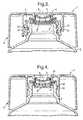
- FIG. 3shows a side section view of an alternative arrangement of the closure shown in FIG. 1, without a valve retaining clip.
- FIG. 4shows a side section view of a closure/container combination according to a second embodiment of the invention, with the transport/storage seal in its opened configuration.
- FIG. 5shows a side section view of a closure according to a third embodiment of the invention, mounted on a container neck with the transport/storage seal in its opened configuration.
- FIG. 6shows a side section view of the closure shown in FIG. 5, with the transport/storage seal in its closed, sealed configuration.
- a closure 1is mounted on the neck portion of a container 2 .
- the closurecomprises a housing 3 , which is adapted to co-operate with the neck portion of the container.
- the housingmay be provided with an internal thread 21 , which co-operates with an external thread 22 on the container neck.
- the housingmay be snap-fitted onto the container neck by means of co-operating snap beads. Ratchets (not shown) are provided on the container neck and housing to prevent rotation of the housing relative to the container.
- the housingdefines a dispensing passageway from the container opening and provides a valve seat 6 around the periphery of the dispensing passageway.
- a flexible, self-closing dispensing valve 5is located in the valve seat 6 and may be held in place by a retaining clip or ring 7 .
- the housingprovides a sealing plate 8 , which partially occludes the container opening, whilst defining a plurality of dispensing apertures 9 around its periphery (see FIG. 1 ). Therefore, it will be clearly understood that the housing 3 including the sealing plate 8 and the valve 5 are all held in fixed orientation relative to one another and to the container 2 .
- the closurefurther comprises a cover 4 disposed on the housing 3 so that it can be raised and lowered relative to the housing.
- the cover 4may be provided with internal threads 31 arranged to co-operate with external threads 32 on the housing.
- the co-operating threads 31 , 32are designed so that approximately a 90° rotation of the cover 4 provides the required axial movement of the cover relative to the housing 3 .
- Stopsare provided on the housing and cover to prevent further rotation of the cover so that it is held captive on the container.
- the covermay be designed for push-pull engagement with the housing by providing suitable stop beads.
- the cover 4also includes an annular projection 11 arranged to engage the flexible periphery of the valve 5 .
- the cover 4In its open, unsealed configuration, the cover 4 is in its raised position relative to the housing 3 , the valve 5 is relaxed (as shown in FIG. 1) and the contents of the container can be dispensed via the dispensing orifices 9 in the sealing plate 8 .
- the cover 4In its closed, sealed configuration, the cover 4 is in its lowered position relative to the housing 3 and the projection 11 stretches the peripheral skirt of the valve 5 down to seal against the sealing plate 8 (as shown in FIG. 2 ), thereby blocking the dispensing apertures 9 .
- the cover 4may be lowered to seal the dispensing passageway and thereby prevent accidental spillage of the container contents caused by overpressure, accidental squeezing of the container etc.
- FIG. 3shows an alternative arrangement of the closure shown in FIGS. 1 and 2, without a retaining clip holding the valve 5 in the valve seat 6 .
- the projection 11 on the cover 4engages the periphery of the valve 5 , even when the cover is in its raised position. Therefore, the projection 11 retains the valve 5 in the valve seat 6 and no retaining clip is required.
- the valve and storage/transport sealoperates in exactly the same way as that described in relation to FIGS. 1 and 2.
- valve seat 6 and sealing plate 8are provided as an integral part of the neck of the container 2 .
- a valve 5is retained in the valve seat 6 .
- the closure 1comprises a cover 4 , which includes a projection 11 to engage the periphery of the valve as described in relation to FIGS. 1 to 3 .
- This arrangementis particularly suited for use where the container is a flexible tube, as such containers are conventionally filled from the end furthest from the neck of the container.
- FIGS. 5 and 6show a third embodiment of the invention in which the valve seat 6 is provided in the cover 4 .
- the valve 5is retained in the cover 4 and is raised and lowered with the cover.
- a housing 3is arranged to co-operate with the neck of a container as described in relation to FIGS. 1 to 3 .
- the housing 3incorporates a sealing plate 8 , which partially occludes the container opening and defines a plurality of dispensing apertures 9 around its periphery.
- the cover 4is arranged to be raised and lowered relative to the housing using either a twisting or push-pull movement.
- the housing 3 and cover 4may be provided with co-operating screw threads or suitably spaced stop beads (not shown).
- valve 5When the cover 4 is in its raised position (as shown in FIG. 5 ), the valve 5 is also in a raised position and the periphery of the valve 10 is held clear of the frustoconical sealing surface provided by plate 8 . The product in the container may then be dispensed through the dispensing apertures 9 (as indicated by the arrows in FIG. 5 ).
- housing 3 and sealing plate 8 shown in FIGS. 5 and 6may equally be provided as an integral part of the container 2 (in the same way as shown in FIG. 4 ). Furthermore, many variations of the valve and sealing arrangement in accordance with the invention will be readily apparent to those skilled in the art.
Landscapes
- Engineering & Computer Science (AREA)
- Mechanical Engineering (AREA)
- Closures For Containers (AREA)
- Containers And Packaging Bodies Having A Special Means To Remove Contents (AREA)
- Medical Preparation Storing Or Oral Administration Devices (AREA)
- Cartons (AREA)
- Preventing Unauthorised Actuation Of Valves (AREA)
- Infusion, Injection, And Reservoir Apparatuses (AREA)
Abstract
Description
Claims (12)
Applications Claiming Priority (3)
| Application Number | Priority Date | Filing Date | Title |
|---|---|---|---|
| GB9912977 | 1999-06-04 | ||
| GBGB9912977.7AGB9912977D0 (en) | 1999-06-04 | 1999-06-04 | Closure with dispensing valve |
| PCT/GB2000/001722WO2000075032A1 (en) | 1999-06-04 | 2000-05-05 | Closure with dispensing valve |
Publications (1)
| Publication Number | Publication Date |
|---|---|
| US6543652B1true US6543652B1 (en) | 2003-04-08 |
Family
ID=10854716
Family Applications (1)
| Application Number | Title | Priority Date | Filing Date |
|---|---|---|---|
| US09/980,459Expired - Fee RelatedUS6543652B1 (en) | 1999-06-04 | 2000-05-05 | Closure with dispensing valve |
Country Status (10)
| Country | Link |
|---|---|
| US (1) | US6543652B1 (en) |
| EP (1) | EP1183191B1 (en) |
| AT (1) | ATE260827T1 (en) |
| AU (1) | AU4590800A (en) |
| BR (1) | BR0011336B1 (en) |
| DE (1) | DE60008723T2 (en) |
| ES (1) | ES2215655T3 (en) |
| GB (1) | GB9912977D0 (en) |
| MX (1) | MXPA01012408A (en) |
| WO (1) | WO2000075032A1 (en) |
Cited By (31)
| Publication number | Priority date | Publication date | Assignee | Title |
|---|---|---|---|---|
| US6672479B2 (en)* | 2001-03-13 | 2004-01-06 | Taisai Kako Co., Ltd./Nihon Tenganyaku | Closing structure of a dispensing container |
| US20050035156A1 (en)* | 2003-08-11 | 2005-02-17 | Michael Hersch | Fluid dispensing apparatus |
| US20060049208A1 (en)* | 2004-09-09 | 2006-03-09 | Daansen Warren S | Slit valves and dispensing nozzles employing same |
| US20060169719A1 (en)* | 2003-08-11 | 2006-08-03 | Bui Xuan S | Manifold assembly |
| US20060171857A1 (en)* | 2003-08-11 | 2006-08-03 | Stead Ronald H | Reagent container and slide reaction and retaining tray, and method of operation |
| US20060173575A1 (en)* | 2003-08-11 | 2006-08-03 | Gilles Lefebvre | Automated reagent dispensing system and method of operation |
| USD530393S1 (en)* | 2005-06-29 | 2006-10-17 | Nordson Corporation | Cover for a dispensing valve |
| US20060231580A1 (en)* | 2005-04-13 | 2006-10-19 | Sonoco Development, Inc. | Twist lock fluid dispensing valve |
| USD552716S1 (en) | 2005-06-29 | 2007-10-09 | Nordson Corporation | Dispensing valve |
| US20070272710A1 (en)* | 2006-05-25 | 2007-11-29 | Sakura Finetek, U.S.A., Inc. | Fluid dispensing apparatus |
| US20070292197A1 (en)* | 2006-06-20 | 2007-12-20 | Craig Peterson | Internal feed manual paint brush |
| US20070295765A1 (en)* | 2004-08-26 | 2007-12-27 | Obrist Closures Switzerland Gmbh | Valve Retaining Device |
| US20080035677A1 (en)* | 2004-09-09 | 2008-02-14 | Daansen Warren S | Nozzle tip with slit valve for fluid dispenser |
| USD576800S1 (en) | 2006-06-20 | 2008-09-16 | Wagner Spray Tech Corporation | Paint brush with asymmetric handle |
| US20080230569A1 (en)* | 2006-11-07 | 2008-09-25 | Mcconville Su Yon | Package comprising push-pull closure and slit valve |
| US20080237271A1 (en)* | 2007-03-27 | 2008-10-02 | Liquid Molding Systems, Inc. | Dispensing valve with improved dispensing |
| US20110163134A1 (en)* | 2010-01-06 | 2011-07-07 | Bloom Kenneth S | Dispensing valve |
| US20120111902A1 (en)* | 2009-07-16 | 2012-05-10 | Seaquist Closures Loffler Gmbh | Dispensing closure |
| US8580568B2 (en) | 2011-09-21 | 2013-11-12 | Sakura Finetek U.S.A., Inc. | Traceability for automated staining system |
| US8752732B2 (en) | 2011-02-01 | 2014-06-17 | Sakura Finetek U.S.A., Inc. | Fluid dispensing system |
| USD720622S1 (en) | 2011-11-30 | 2015-01-06 | Tc Heartland Llc | Bottle with cap |
| US8932543B2 (en) | 2011-09-21 | 2015-01-13 | Sakura Finetek U.S.A., Inc. | Automated staining system and reaction chamber |
| USD738732S1 (en) | 2011-11-30 | 2015-09-15 | Tc Heartland Llc | Bottle with cap |
| US20170057710A1 (en)* | 2015-08-24 | 2017-03-02 | Juergen Greiner-Perth | Discharge head for a fluid dispenser and fluid dispenser |
| US20180084888A1 (en)* | 2016-09-23 | 2018-03-29 | The Beachwaver Co. | Liquid dispensing cap |
| JP2018070225A (en)* | 2016-10-31 | 2018-05-10 | 株式会社吉野工業所 | Spout cap |
| US10442584B2 (en)* | 2015-02-03 | 2019-10-15 | Weener Plastics Netherlands B.V. | Dispensing closure with self-closing valve |
| US10836541B2 (en) | 2017-11-27 | 2020-11-17 | Gateway Plastics, Inc. | Valve for a dispensing container |
| US11066218B2 (en)* | 2016-11-17 | 2021-07-20 | Aptar Radolfzell Gmbh | Discharge head, and liquid dispenser comprising such a discharge head |
| US11077993B2 (en)* | 2016-11-17 | 2021-08-03 | Aptar Radolfzell Gmbh | Discharge head for a liquid dispenser and liquid dispenser having such a discharge head |
| US12371233B2 (en) | 2020-10-19 | 2025-07-29 | Aptargroup, Inc. | Valve |
Families Citing this family (3)
| Publication number | Priority date | Publication date | Assignee | Title |
|---|---|---|---|---|
| US7699193B2 (en) | 1999-07-29 | 2010-04-20 | Weener Plastik Gmbh & Co., Kg | Self-closing valve |
| FR2814723B1 (en)* | 2000-10-03 | 2003-04-11 | Oreal | DISPENSING HEAD AND CONTAINER PROVIDED WITH SUCH A HEAD |
| GB201904882D0 (en)* | 2019-04-05 | 2019-05-22 | Magecup Ltd | Fluid vessel closure device |
Citations (4)
| Publication number | Priority date | Publication date | Assignee | Title |
|---|---|---|---|---|
| US5115950A (en)* | 1991-01-14 | 1992-05-26 | Seaquist Closures A Divison Of Pittway Corporation | Dispensing closure with unitary structure for retaining a pressure-actuated flexible valve |
| WO1997022520A1 (en) | 1995-12-19 | 1997-06-26 | Tetra Laval Holdings & Finance S.A. | Method for producing a plastic container and preform for producing a plastic container |
| US5680969A (en)* | 1995-12-18 | 1997-10-28 | Aptargroup, Inc. | Closure with dispensing valve and separate releasable internal shipping seal |
| US6290108B1 (en)* | 2000-04-14 | 2001-09-18 | Seaquist Closures Foreign, Inc. | Dispensing system with an internal releasable shipping seal and an extended tip containing a pressure openable valve |
Family Cites Families (4)
| Publication number | Priority date | Publication date | Assignee | Title |
|---|---|---|---|---|
| US3887116A (en)* | 1972-09-01 | 1975-06-03 | Shiseido Co Ltd | Receptacle for liquid material |
| DE8235857U1 (en)* | 1982-12-21 | 1984-05-24 | Wella Ag, 6100 Darmstadt | Automatic closure for flexible containers |
| US4941598A (en)* | 1988-11-08 | 1990-07-17 | Ortho Pharmaceutical Corporation | Dosing cap |
| US5271531A (en)* | 1991-01-14 | 1993-12-21 | Seaquist Closures, A Division Of Pittway Corp. | Dispensing closure with pressure-actuated flexible valve |
- 1999
- 1999-06-04GBGBGB9912977.7Apatent/GB9912977D0/ennot_activeCeased
- 2000
- 2000-05-05BRBRPI0011336-0Apatent/BR0011336B1/ennot_activeIP Right Cessation
- 2000-05-05AUAU45908/00Apatent/AU4590800A/ennot_activeAbandoned
- 2000-05-05WOPCT/GB2000/001722patent/WO2000075032A1/enactiveIP Right Grant
- 2000-05-05USUS09/980,459patent/US6543652B1/ennot_activeExpired - Fee Related
- 2000-05-05ESES00927511Tpatent/ES2215655T3/ennot_activeExpired - Lifetime
- 2000-05-05MXMXPA01012408Apatent/MXPA01012408A/enactiveIP Right Grant
- 2000-05-05ATAT00927511Tpatent/ATE260827T1/ennot_activeIP Right Cessation
- 2000-05-05EPEP00927511Apatent/EP1183191B1/ennot_activeExpired - Lifetime
- 2000-05-05DEDE2000608723patent/DE60008723T2/ennot_activeExpired - Lifetime
Patent Citations (4)
| Publication number | Priority date | Publication date | Assignee | Title |
|---|---|---|---|---|
| US5115950A (en)* | 1991-01-14 | 1992-05-26 | Seaquist Closures A Divison Of Pittway Corporation | Dispensing closure with unitary structure for retaining a pressure-actuated flexible valve |
| US5680969A (en)* | 1995-12-18 | 1997-10-28 | Aptargroup, Inc. | Closure with dispensing valve and separate releasable internal shipping seal |
| WO1997022520A1 (en) | 1995-12-19 | 1997-06-26 | Tetra Laval Holdings & Finance S.A. | Method for producing a plastic container and preform for producing a plastic container |
| US6290108B1 (en)* | 2000-04-14 | 2001-09-18 | Seaquist Closures Foreign, Inc. | Dispensing system with an internal releasable shipping seal and an extended tip containing a pressure openable valve |
Cited By (56)
| Publication number | Priority date | Publication date | Assignee | Title |
|---|---|---|---|---|
| US6672479B2 (en)* | 2001-03-13 | 2004-01-06 | Taisai Kako Co., Ltd./Nihon Tenganyaku | Closing structure of a dispensing container |
| US20050035156A1 (en)* | 2003-08-11 | 2005-02-17 | Michael Hersch | Fluid dispensing apparatus |
| US20060169719A1 (en)* | 2003-08-11 | 2006-08-03 | Bui Xuan S | Manifold assembly |
| US20060171857A1 (en)* | 2003-08-11 | 2006-08-03 | Stead Ronald H | Reagent container and slide reaction and retaining tray, and method of operation |
| US20060173575A1 (en)* | 2003-08-11 | 2006-08-03 | Gilles Lefebvre | Automated reagent dispensing system and method of operation |
| US9518899B2 (en) | 2003-08-11 | 2016-12-13 | Sakura Finetek U.S.A., Inc. | Automated reagent dispensing system and method of operation |
| US7767152B2 (en) | 2003-08-11 | 2010-08-03 | Sakura Finetek U.S.A., Inc. | Reagent container and slide reaction retaining tray, and method of operation |
| US7744817B2 (en) | 2003-08-11 | 2010-06-29 | Sakura Finetek U.S.A., Inc. | Manifold assembly |
| US7501283B2 (en) | 2003-08-11 | 2009-03-10 | Sakura Finetek U.S.A., Inc. | Fluid dispensing apparatus |
| US20070295765A1 (en)* | 2004-08-26 | 2007-12-27 | Obrist Closures Switzerland Gmbh | Valve Retaining Device |
| US8978939B2 (en)* | 2004-08-26 | 2015-03-17 | Obrist Closures Switzerland Gmbh | Valve retaining device |
| US20080035677A1 (en)* | 2004-09-09 | 2008-02-14 | Daansen Warren S | Nozzle tip with slit valve for fluid dispenser |
| US8899449B2 (en)* | 2004-09-09 | 2014-12-02 | Warren S. Daansen | Nozzle tip with slit valve for fluid dispenser |
| US20060049208A1 (en)* | 2004-09-09 | 2006-03-09 | Daansen Warren S | Slit valves and dispensing nozzles employing same |
| US9254498B2 (en) | 2004-09-09 | 2016-02-09 | Warren S. Daansen | Nozzle tip with slit valve for fluid dispenser |
| US9714714B2 (en) | 2004-09-09 | 2017-07-25 | Warren S. Daansen | Nozzle tip with slit valve for fluid dispenser |
| US20060231580A1 (en)* | 2005-04-13 | 2006-10-19 | Sonoco Development, Inc. | Twist lock fluid dispensing valve |
| USD530393S1 (en)* | 2005-06-29 | 2006-10-17 | Nordson Corporation | Cover for a dispensing valve |
| USD552716S1 (en) | 2005-06-29 | 2007-10-09 | Nordson Corporation | Dispensing valve |
| US20070272710A1 (en)* | 2006-05-25 | 2007-11-29 | Sakura Finetek, U.S.A., Inc. | Fluid dispensing apparatus |
| US8459509B2 (en) | 2006-05-25 | 2013-06-11 | Sakura Finetek U.S.A., Inc. | Fluid dispensing apparatus |
| US9914124B2 (en) | 2006-05-25 | 2018-03-13 | Sakura Finetek U.S.A., Inc. | Fluid dispensing apparatus |
| US7854562B2 (en) | 2006-06-20 | 2010-12-21 | Wagner Spray Tech Corporation | Internal feed manual paint brush |
| US20070292197A1 (en)* | 2006-06-20 | 2007-12-20 | Craig Peterson | Internal feed manual paint brush |
| USD576800S1 (en) | 2006-06-20 | 2008-09-16 | Wagner Spray Tech Corporation | Paint brush with asymmetric handle |
| US20080230569A1 (en)* | 2006-11-07 | 2008-09-25 | Mcconville Su Yon | Package comprising push-pull closure and slit valve |
| US7874466B2 (en) | 2006-11-07 | 2011-01-25 | The Procter & Gamble Company | Package comprising push-pull closure and slit valve |
| US8397956B2 (en)* | 2007-03-27 | 2013-03-19 | Aptargroup, Inc. | Dispensing valve with improved dispensing |
| US20080237271A1 (en)* | 2007-03-27 | 2008-10-02 | Liquid Molding Systems, Inc. | Dispensing valve with improved dispensing |
| US20120111902A1 (en)* | 2009-07-16 | 2012-05-10 | Seaquist Closures Loffler Gmbh | Dispensing closure |
| US8408432B2 (en)* | 2009-07-16 | 2013-04-02 | Aptar Freyung Gmbh | Dispensing closure |
| US8794489B2 (en) | 2010-01-06 | 2014-08-05 | Berry Plastics Corporation | Dispensing valve |
| US8397957B2 (en)* | 2010-01-06 | 2013-03-19 | Berry Plastics Corporation | Dispensing valve |
| US20110163134A1 (en)* | 2010-01-06 | 2011-07-07 | Bloom Kenneth S | Dispensing valve |
| US8752732B2 (en) | 2011-02-01 | 2014-06-17 | Sakura Finetek U.S.A., Inc. | Fluid dispensing system |
| US9016526B2 (en) | 2011-02-01 | 2015-04-28 | Sakura Finetek U.S.A., Inc. | Fluid dispensing system |
| US10295444B2 (en) | 2011-09-21 | 2019-05-21 | Sakura Finetek U.S.A., Inc. | Automated staining system and reaction chamber |
| US9005980B2 (en) | 2011-09-21 | 2015-04-14 | Sakura Finetek U.S.A., Inc. | Traceability for automated staining system |
| US12281970B2 (en) | 2011-09-21 | 2025-04-22 | Sakura Finetek U.S.A., Inc. | Automated staining system and reaction chamber |
| US8932543B2 (en) | 2011-09-21 | 2015-01-13 | Sakura Finetek U.S.A., Inc. | Automated staining system and reaction chamber |
| US8580568B2 (en) | 2011-09-21 | 2013-11-12 | Sakura Finetek U.S.A., Inc. | Traceability for automated staining system |
| USD932902S1 (en) | 2011-11-30 | 2021-10-12 | Tc Heartland Llc | Bottle with cap |
| USD720622S1 (en) | 2011-11-30 | 2015-01-06 | Tc Heartland Llc | Bottle with cap |
| USD817175S1 (en) | 2011-11-30 | 2018-05-08 | Tc Heartland Llc | Bottle and cap |
| USD738732S1 (en) | 2011-11-30 | 2015-09-15 | Tc Heartland Llc | Bottle with cap |
| US10442584B2 (en)* | 2015-02-03 | 2019-10-15 | Weener Plastics Netherlands B.V. | Dispensing closure with self-closing valve |
| US10173815B2 (en)* | 2015-08-24 | 2019-01-08 | Aptar Radolfzell Gmbh | Discharge head for a fluid dispenser and fluid dispenser |
| CN106475247A (en)* | 2015-08-24 | 2017-03-08 | 阿普塔尔拉多尔夫策尔有限责任公司 | Discharge head and fluid distributor for fluid distributor |
| US20170057710A1 (en)* | 2015-08-24 | 2017-03-02 | Juergen Greiner-Perth | Discharge head for a fluid dispenser and fluid dispenser |
| US20180084888A1 (en)* | 2016-09-23 | 2018-03-29 | The Beachwaver Co. | Liquid dispensing cap |
| JP2018070225A (en)* | 2016-10-31 | 2018-05-10 | 株式会社吉野工業所 | Spout cap |
| US11077993B2 (en)* | 2016-11-17 | 2021-08-03 | Aptar Radolfzell Gmbh | Discharge head for a liquid dispenser and liquid dispenser having such a discharge head |
| US11066218B2 (en)* | 2016-11-17 | 2021-07-20 | Aptar Radolfzell Gmbh | Discharge head, and liquid dispenser comprising such a discharge head |
| US11377266B2 (en) | 2017-11-27 | 2022-07-05 | Silgan Specialty Packaging Llc | Valve for a dispensing container |
| US10836541B2 (en) | 2017-11-27 | 2020-11-17 | Gateway Plastics, Inc. | Valve for a dispensing container |
| US12371233B2 (en) | 2020-10-19 | 2025-07-29 | Aptargroup, Inc. | Valve |
Also Published As
| Publication number | Publication date |
|---|---|
| EP1183191B1 (en) | 2004-03-03 |
| GB9912977D0 (en) | 1999-08-04 |
| DE60008723T2 (en) | 2005-01-13 |
| ATE260827T1 (en) | 2004-03-15 |
| BR0011336B1 (en) | 2010-07-27 |
| WO2000075032A1 (en) | 2000-12-14 |
| AU4590800A (en) | 2000-12-28 |
| MXPA01012408A (en) | 2002-08-30 |
| DE60008723D1 (en) | 2004-04-08 |
| ES2215655T3 (en) | 2004-10-16 |
| BR0011336A (en) | 2002-03-05 |
| EP1183191A1 (en) | 2002-03-06 |
Similar Documents
| Publication | Publication Date | Title |
|---|---|---|
| US6543652B1 (en) | Closure with dispensing valve | |
| US5632420A (en) | Dispensing package | |
| US5071017A (en) | Closure cap construction with slitted flexible diaphragm | |
| US5904275A (en) | Closure with self-closing valve | |
| US5794803A (en) | Child-resistant measuring cup closure and dispensing container | |
| EP1842789B1 (en) | System including a closure and a container attachment | |
| US6062441A (en) | Two-piece dispensing closure | |
| AU766739B2 (en) | One-piece dispensing system and method for making same | |
| US4519529A (en) | Dispensing stopper | |
| CA2020048A1 (en) | Flexible dispensing closure | |
| JP2004537483A (en) | Deformable distribution valve | |
| CA2524477C (en) | Valve closure | |
| US2901153A (en) | Dispensing valve | |
| US5234138A (en) | Self-closing dispenser for a container containing a liquid or pasty product | |
| US4141475A (en) | Locking device for a self-closing closure | |
| US4164377A (en) | Dual-seal, ball-type dispensing package | |
| US20090120899A1 (en) | Flip top container closure | |
| US5121859A (en) | Non-resealable dispenser cap construction | |
| GB2258860A (en) | Valved closure | |
| GB2330577A (en) | Dispensing valve with a slitted diaphragm and retention ring | |
| US4402434A (en) | Flow responsive closure device | |
| US3120908A (en) | One-piece plastic resealing spout | |
| US3405850A (en) | Screw actuated toggle valve dispensing cap | |
| WO2006116248A1 (en) | Tip design for reducing capillary leakage and water loss for plastic container closures | |
| US6840409B2 (en) | Packaging for fluid product with hinge closure |
Legal Events
| Date | Code | Title | Description |
|---|---|---|---|
| AS | Assignment | Owner name:CROWN CORK & SEAL TECHNOLOGIES CORPORATION, ILLINO Free format text:ASSIGNMENT OF ASSIGNORS INTEREST;ASSIGNORS:KELDER, MARIA LOUISE;RAMSEY, CHRISTOPHER PAUL;REEL/FRAME:012929/0634;SIGNING DATES FROM 20011004 TO 20011130 | |
| AS | Assignment | Owner name:CITICORP NORTH AMERICA, INC., NEW YORK Free format text:SECURITY AGREEMENT;ASSIGNOR:CROWN TECHNOLOGIES PACKAGING CORPORATION;REEL/FRAME:016283/0612 Effective date:20040901 | |
| FEPP | Fee payment procedure | Free format text:PAYOR NUMBER ASSIGNED (ORIGINAL EVENT CODE: ASPN); ENTITY STATUS OF PATENT OWNER: LARGE ENTITY | |
| AS | Assignment | Owner name:CROWN OBRIST GMBH, SWITZERLAND Free format text:ASSIGNMENT OF ASSIGNORS INTEREST;ASSIGNOR:CROWN PACKAGING TECHNOLOGY, INC.;REEL/FRAME:017546/0384 Effective date:20051011 | |
| FPAY | Fee payment | Year of fee payment:4 | |
| AS | Assignment | Owner name:CROWN PACKAGING TECHNOLOGY, INC., ILLINOIS Free format text:CHANGE OF NAME;ASSIGNOR:CROWN CORK & SEAL TECHNOLOGIES CORPORATION;REEL/FRAME:018573/0199 Effective date:20031103 | |
| AS | Assignment | Owner name:OBRIST CLOSURES SWITZERLAND GMBH, SWITZERLAND Free format text:ASSIGNMENT OF ASSIGNORS INTEREST;ASSIGNOR:CROWN OBRIST GMBH;REEL/FRAME:018645/0465 Effective date:20051220 | |
| FEPP | Fee payment procedure | Free format text:PAYOR NUMBER ASSIGNED (ORIGINAL EVENT CODE: ASPN); ENTITY STATUS OF PATENT OWNER: LARGE ENTITY Free format text:PAYER NUMBER DE-ASSIGNED (ORIGINAL EVENT CODE: RMPN); ENTITY STATUS OF PATENT OWNER: LARGE ENTITY | |
| FPAY | Fee payment | Year of fee payment:8 | |
| AS | Assignment | Owner name:CROWN PACKAGING TECHNOLOGY, INC., ILLINOIS Free format text:RELEASE BY SECURED PARTY;ASSIGNOR:CITICORP NORTH AMERICA, INC.;REEL/FRAME:032449/0281 Effective date:20140314 | |
| REMI | Maintenance fee reminder mailed | ||
| LAPS | Lapse for failure to pay maintenance fees | ||
| STCH | Information on status: patent discontinuation | Free format text:PATENT EXPIRED DUE TO NONPAYMENT OF MAINTENANCE FEES UNDER 37 CFR 1.362 | |
| FP | Lapsed due to failure to pay maintenance fee | Effective date:20150408 |