US6543272B1 - Systems and methods for testing and calibrating a focused ultrasound transducer array - Google Patents
Systems and methods for testing and calibrating a focused ultrasound transducer arrayDownload PDFInfo
- Publication number
- US6543272B1 US6543272B1US09/557,050US55705000AUS6543272B1US 6543272 B1US6543272 B1US 6543272B1US 55705000 AUS55705000 AUS 55705000AUS 6543272 B1US6543272 B1US 6543272B1
- Authority
- US
- United States
- Prior art keywords
- transducer
- ultrasonic signal
- received
- acoustic reflector
- sensing element
- Prior art date
- Legal status (The legal status is an assumption and is not a legal conclusion. Google has not performed a legal analysis and makes no representation as to the accuracy of the status listed.)
- Expired - Lifetime
Links
- 238000002604ultrasonographyMethods0.000titleclaimsabstractdescription32
- 238000000034methodMethods0.000titleclaimsabstractdescription30
- 238000012360testing methodMethods0.000titleclaimsabstractdescription26
- 230000010363phase shiftEffects0.000claimsabstractdescription27
- 238000012545processingMethods0.000claimsabstractdescription25
- 238000011156evaluationMethods0.000claims1
- 239000012530fluidSubstances0.000description8
- XLYOFNOQVPJJNP-UHFFFAOYSA-NwaterSubstancesOXLYOFNOQVPJJNP-UHFFFAOYSA-N0.000description8
- 238000004364calculation methodMethods0.000description4
- 239000012528membraneSubstances0.000description4
- 238000000527sonicationMethods0.000description4
- 206010028980NeoplasmDiseases0.000description3
- 238000004458analytical methodMethods0.000description3
- 238000006880cross-coupling reactionMethods0.000description3
- 230000006870functionEffects0.000description3
- 238000001356surgical procedureMethods0.000description3
- 230000002159abnormal effectEffects0.000description2
- 230000006399behaviorEffects0.000description2
- 230000015556catabolic processEffects0.000description2
- 238000006731degradation reactionMethods0.000description2
- 238000010586diagramMethods0.000description2
- 230000005284excitationEffects0.000description2
- 238000002595magnetic resonance imagingMethods0.000description2
- 239000000463materialSubstances0.000description2
- 238000012986modificationMethods0.000description2
- 230000004048modificationEffects0.000description2
- 230000008569processEffects0.000description2
- 230000004044responseEffects0.000description2
- 238000002560therapeutic procedureMethods0.000description2
- 229920002799BoPETPolymers0.000description1
- 206010020843HyperthermiaDiseases0.000description1
- 239000005041Mylar™Substances0.000description1
- 206010028851NecrosisDiseases0.000description1
- 230000032683agingEffects0.000description1
- 238000003491arrayMethods0.000description1
- 230000008859changeEffects0.000description1
- 230000003750conditioning effectEffects0.000description1
- 238000010276constructionMethods0.000description1
- 230000008878couplingEffects0.000description1
- 238000010168coupling processMethods0.000description1
- 238000005859coupling reactionMethods0.000description1
- 230000003247decreasing effectEffects0.000description1
- 230000003111delayed effectEffects0.000description1
- 230000000694effectsEffects0.000description1
- 238000010438heat treatmentMethods0.000description1
- 230000036031hyperthermiaEffects0.000description1
- 238000003384imaging methodMethods0.000description1
- 238000004519manufacturing processMethods0.000description1
- 238000005259measurementMethods0.000description1
- 238000012544monitoring processMethods0.000description1
- 239000004033plasticSubstances0.000description1
- 229920003023plasticPolymers0.000description1
- 239000004800polyvinyl chlorideSubstances0.000description1
- 229920002379silicone rubberPolymers0.000description1
- 239000004945silicone rubberSubstances0.000description1
- 238000010998test methodMethods0.000description1
- 230000001131transforming effectEffects0.000description1
Images


Classifications
- B—PERFORMING OPERATIONS; TRANSPORTING
- B06—GENERATING OR TRANSMITTING MECHANICAL VIBRATIONS IN GENERAL
- B06B—METHODS OR APPARATUS FOR GENERATING OR TRANSMITTING MECHANICAL VIBRATIONS OF INFRASONIC, SONIC, OR ULTRASONIC FREQUENCY, e.g. FOR PERFORMING MECHANICAL WORK IN GENERAL
- B06B1/00—Methods or apparatus for generating mechanical vibrations of infrasonic, sonic, or ultrasonic frequency
- B06B1/02—Methods or apparatus for generating mechanical vibrations of infrasonic, sonic, or ultrasonic frequency making use of electrical energy
- B06B1/0207—Driving circuits
- A—HUMAN NECESSITIES
- A61—MEDICAL OR VETERINARY SCIENCE; HYGIENE
- A61N—ELECTROTHERAPY; MAGNETOTHERAPY; RADIATION THERAPY; ULTRASOUND THERAPY
- A61N7/00—Ultrasound therapy
- A61N7/02—Localised ultrasound hyperthermia
- A—HUMAN NECESSITIES
- A61—MEDICAL OR VETERINARY SCIENCE; HYGIENE
- A61B—DIAGNOSIS; SURGERY; IDENTIFICATION
- A61B17/00—Surgical instruments, devices or methods
- A61B2017/00681—Aspects not otherwise provided for
- A61B2017/00725—Calibration or performance testing
- B—PERFORMING OPERATIONS; TRANSPORTING
- B06—GENERATING OR TRANSMITTING MECHANICAL VIBRATIONS IN GENERAL
- B06B—METHODS OR APPARATUS FOR GENERATING OR TRANSMITTING MECHANICAL VIBRATIONS OF INFRASONIC, SONIC, OR ULTRASONIC FREQUENCY, e.g. FOR PERFORMING MECHANICAL WORK IN GENERAL
- B06B2201/00—Indexing scheme associated with B06B1/0207 for details covered by B06B1/0207 but not provided for in any of its subgroups
- B06B2201/40—Indexing scheme associated with B06B1/0207 for details covered by B06B1/0207 but not provided for in any of its subgroups with testing, calibrating, safety devices, built-in protection, construction details
- B—PERFORMING OPERATIONS; TRANSPORTING
- B06—GENERATING OR TRANSMITTING MECHANICAL VIBRATIONS IN GENERAL
- B06B—METHODS OR APPARATUS FOR GENERATING OR TRANSMITTING MECHANICAL VIBRATIONS OF INFRASONIC, SONIC, OR ULTRASONIC FREQUENCY, e.g. FOR PERFORMING MECHANICAL WORK IN GENERAL
- B06B2201/00—Indexing scheme associated with B06B1/0207 for details covered by B06B1/0207 but not provided for in any of its subgroups
- B06B2201/70—Specific application
- B06B2201/76—Medical, dental
Definitions
- the present inventionrelates generally to systems and methods for performing noninvasive surgical procedures using focused ultrasound, and more particularly to systems and methods for testing and calibrating a focused ultrasound transducer array.
- High intensity focused acoustic wavessuch as ultrasonic waves (acoustic waves with a frequency greater than about 20 kilohertz), may be used to therapeutically treat internal tissue regions within a patient.
- ultrasonic wavesmay be used to ablate tumors, thereby obviating the need for invasive surgery.
- piezoelectric transducers driven by electric signals to produce ultrasonic energyhave been suggested that may be placed external to the patient but in close proximity to the tissue to be ablated.
- the transduceris geometrically shaped and positioned such that the ultrasonic energy is focused at a “focal zone” corresponding to a target tissue region within the patient, heating the target tissue region until the tissue is necrosed.
- the transducermay be sequentially focused and activated at a number of focal zones in close proximity to one another. This series of sonications is used to cause coagulation necrosis of an entire tissue structure, such as a tumor, of a desired size and shape.
- a spherical cap transducer arraysuch as that disclosed in U.S. Pat. No. 4,865,042 issued to Umemura et al., has been suggested for this purpose.
- This spherical cap transducer arrayincludes a plurality of concentric rings disposed on a curved surface having a radius of curvature defining a portion of a sphere.
- the concentric ringsgenerally have equal surface areas and may also be divided circumferentially into a plurality of curved transducer elements or “sectors,” creating a sector-vortex array.
- the transducer elementsare generally simultaneously driven by radio frequency (RF) electrical signals at a single frequency offset in phase and amplitude.
- RFradio frequency
- phase and amplitude of the respective drive signalsmay be controlled so as to focus the emitted ultrasonic energy at a desired “focal distance,” i.e., the distance from the transducer to the center of the focal zone, and/or to provide a desired energy level in the target tissue region.
- phase of the respective drive signals to each of the sectorsmay be controlled to create a desired size and shape for the focal zone.
- Transducer arraysare generally composed of numerous transducer elements that may be difficult and/or costly to fabricate and require complex drive circuitry and hardware to control and power. As part of its initial production and assembly, a focused ultrasound system is generally tested and configured, for example, to ensure that the individual transducer elements of the transducer array and/or the drive and control circuitry perform properly.
- the systemmay be susceptible to degradation in performance and/or possible failure of some of the transducer elements. This degradation may be caused by normal aging processes and/or by misuse of the system. For example, the piezoelectric material forming the transducer elements may age, possibly changing their impedance or efficiency. Likewise, problems may develop in the drive circuitry during the life of the system.
- a methodfor testing the performance of a focused ultrasound transducer array.
- An acoustic reflectoris located at a position to receive ultrasonic energy transmitted by the transducer array. Ultrasonic energy is transmitted from the transducer array, the ultrasonic energy is reflected off of the reflector, and is received by a sensing element. The performance of the transducer array is then evaluated based upon the received reflected ultrasonic energy.
- the reflectoris preferably provided with well-defined and predictable ultrasonic reflection characteristics, and may be positioned at any location within the acoustic view of the transducer array.
- the reflectormay be a planar acoustic reflector, such as an “air mirror,” placed between the acoustic fluid in which the transducer is disposed and the air above the surface of the acoustic fluid.
- the reflectormay be a curved reflector or a point reflector.
- a planar reflectormay be located between the transducer and its geometric focal point, preferably half-way between them.
- incidental ultrasonic energymay be reflected off of.the reflector to a single point located at the center of the transducer array, i.e., to its “virtual” geometric focal point.
- a point reflectorit may be located at the actual geometric focal point of the transducer array.
- the reflected ultrasonic energymay be received, for example, at the virtual geometric focal point of the transducer array.
- the performance of the transducer arraymay then be quantified based on an analysis of the received ultrasonic energy.
- the performance of the transducer arrayis quantified by exciting individual transducer elements in the transducer array and comparing one or more actual characteristics of the received ultrasonic signals, e.g., gain and/or delay, to expected characteristics of the received ultrasonic signals.
- the expected characteristics of the received ultrasonic signalmay be obtained from an acoustic model of the testing system.
- the acoustic wave modelingis facilitated because the bore-sight of the reflected ultrasonic energy is incident at the point of reception, regardless of the location of the individual transducer element from which it originates. Thus, no off-bore-sight sight calculations need be made.
- the quantified performance of the transducer arraymay then be used, for example, to calibrate the transducer array and/or to declare a system failure should the performance of the transducer array be severely degraded.
- a methodfor testing a focused ultrasound transducer array having a plurality of transducer elements.
- An acoustic reflectorsuch as a planar reflector, is positioned adjacent the transducer array, and a plurality of reflected ultrasonic signals are produced by transmitting a plurality of ultrasonic signals from the plurality of transducer elements towards the acoustic reflector.
- the ultrasonic signalsmay be transmitted by exciting individual transducer elements or a set of transducer elements.
- the transducer arraymay have a concave or spherical cap shape, and the acoustic reflector may be an “air mirror” located half-way between the transducer array and its geometric focal point.
- the plurality of reflected ultrasonic signalsmay be received and one or more actual ultrasonic reflection characteristics, such as gain and/or delay, may obtained from each of the plurality of received ultrasonic signals.
- the plurality of actual ultrasonic reflection characteristicsmay then be compared with a plurality of expected ultrasonic reflection characteristics.
- the delay of each of the received ultrasonic signals with respect to the transmitted ultrasonic signalsis determined, which may be an actual time delay (for pulsed signals) or a phase shift between the signals (for sinusoidal signals).
- the gain of each of the received ultrasonic signalsmay be obtained by comparing the amplitudes of the plurality of received ultrasonic signals with the corresponding amplitudes of the plurality of transmitted ultrasonic signals. This may be accomplished, for example, by comparing electrical signals produced by a sensing element representative of the received ultrasonic signals with electrical signals used to generate the transmitted ultrasonic signals, i.e., the corresponding electrical signals used to excite the transducer elements into producing the plurality of ultrasonic signals.
- the actual ultrasonic reflection characteristicsmay be compared with a respective plurality of expected ultrasonic reflection characteristics.
- the expected characteristics of the received ultrasonic energymay be obtained from an acoustic model of the testing system.
- the transducer arraymay then be calibrated, or alternatively, a system failure may be declared, based upon the ultrasonic reflection characteristic comparison.
- an ultrasound systemin accordance with a third aspect of the present invention, includes a focused ultrasound transducer for emitting ultrasonic energy, a passive acoustic reflector for reflecting ultrasonic energy emitted by the transducer, and an ultrasound sensing element for sensing the reflected ultrasonic energy.
- the transducermay, for example, be a phased transducer array used to treat abnormal tissue within a patient.
- the shape of the transducertakes the form of a spherical cap, but alternatively may take on any suitable shape that enables the focusing of ultrasonic energy.
- the reflectoris an air mirror located half-way between the transducer and its geometric focal point.
- the sensing elementmay be located at a single point at the center of the transducer.
- the geometry of the reflectormay be any shape that provides well-defined and predictable acoustic reflection characteristics, and may be located anywhere within the view of the transducer.
- the systemfurther includes processing circuitry coupled to the sensing element for measuring actual characteristic(s) of the received ultrasonic signals, e.g., the amplitude and/or phase.
- the processing circuitrymay also be coupled to drive circuitry used to excite the transducer into emitting the ultrasonic energy.
- the processing circuitrymay compare the amplitude and phase of the received ultrasonic signal with the amplitude and phase of the emitted ultrasonic signal.
- the systemfurther includes a controller coupled to the processing circuitry for comparing the actual characteristic(s) of the received ultrasonic energy, e.g., the gain and/or delay (or phase shift), to expected characteristic(s) of the sensed ultrasonic energy.
- the controller and processing circuitrymay both be a single integral component, such as a personal computer with special boards added (such as acquisition boards), or other microprocessor, or alternatively, may be separate components.
- the controllermay then use the difference information to calibrate the emitting transducer and/or to declare a system failure if need be.
- FIG. 1is a schematic diagram of a focused ultrasound system, in accordance with the present invention.
- FIG. 2is a top view of the transducer array of the focused ultrasound system of FIG. 1;
- FIG. 3is a schematic side view of a patient on a water-filled table having an ultrasound transducer array therein;
- FIG. 4is a schematic side view of a test setup for testing the ultrasound system of FIG. 1;
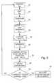
- FIG. 5is a flow diagram of a preferred method of testing the ultrasound system of FIG. 1 .
- FIG. 1shows a preferred embodiment of a focused ultrasound system 10 , constructed in accordance with the present invention.
- the system 10may be operated to advantageously focus ultrasonic energy at a “focal zone” or desired target region in space for purposes of providing therapy to a patient, e.g., for treating abnormal tissue within the patient.
- the system 10generally includes an ultrasound emitting transducer 12 for emitting ultrasonic energy U EMIT , driver circuitry 14 for providing electrical drive signals S EMIT to the transducer 12 , and a controller 16 for controlling the characteristics of the drive signals S EMIT output from the driver circuitry 14 , and thus, the characteristics of the emitted ultrasonic energy U EMIT .
- the transducer 12is preferably a phased array ultrasound transducer formed from piezoelectric material, constructed as is known to those skilled in the art.
- the transducer 12has a concave or bowl shape, preferably a “spherical cap” shape, i.e., having a substantially constant radius of curvature 24 , such that the transducer 12 has an inside surface 26 defining a portion of a sphere 28 .
- the transducer 12has a geometric focal point FP, which, in the case of a spherical cap transducer array, is coincident with the center of the sphere.
- the transducer 12includes a plurality of transducer elements 30 , such as concentric rings 32 - 1 to 32 - 9 , which may be formed by cutting concentric circles through a piezoelectric shell (not shown).
- each of the rings 32has substantially the same surface area, and thus, the widths of the rings 32 are progressively smaller from the innermost ring 32 - 1 outward to the outermost ring 32 - 9 . Any spaces (not shown) between the rings 32 may be filled with silicone rubber and the like to substantially isolate the rings 32 from one another.
- Each ring 32may also be divided circumferentially into curved elements or “sectors” 34 - 1 to 34 - 6 .
- phased array transducerappropriate for use with the present invention may be found, for example, in T. Fjield and K. Hynynen, “The Combined Concentric-Ring and Sector-Vortex Phased Array for MRI Guided Ultrasound Surgery,” IEEE Transactions on Ultrasonics, Ferroelectrics, and Frequency Control, vol. 44, no. 5, pages 1157-1167 (September 1997), the disclosure of which is expressly incorporated herein by reference.
- a concentric-ring transducermay be provided that is not divided into circumferential sectors (not shown), such as that described in C. Cain and S.
- each of the transducer elements 30is individually coupled to the driver circuitry 14 in a conventional manner.
- the driver circuitry 14is configured to provide electrical drive signals S EMIT to the transducer elements 30 at a plurality of discrete frequencies, preferably at radio frequencies (RF), for example, between about 0.5 to 10 MHz, and more preferably between about 1 to 2 MHz.
- RFradio frequencies
- the controller 16is coupled to the driver circuitry 14 for controlling several aspects of the drive signals S EMIT generated by the driver circuitry 14 , such as the frequency, phase, and/or amplitude.
- the controller 16may control the amplitude of the drive signals S EMIT , for example, to control the intensity of emitted ultrasonic energy U EMIT .
- the controller 16may control the phase between each of the concentric rings 32 and/or between each of the sectors 34 . By shifting the phase between the concentric rings 32 , the “focal distance,” i.e., the distance from the transducer 12 to the center of the focal zone, may be adjusted, for example, along the z axis.
- the location of the center of the focal zone of the emitted ultrasonic energy U EMITmay differ from the geometric focal point FP of the transducer 12 .
- Shifting the phase between the sectors 34 (“mode n”)allows control of the size and shape of the focal zone of the transducer 12 .
- the controller 16also preferably controls the frequency of the drive signals S EMIT provided to the transducer 12 .
- the drive signals S EMIT supplied to the transducer 12 at one timeare all preferably provided at the same discrete frequency. This discrete frequency may be maintained during a single sonication. Alternatively, the frequency may be varied during the sonication to minimize the effects of secondary hot spots.
- Such a system and methodis described in co-pending application Ser. No. 09/556,095, which was filed on the same date and assigned to the same assignee as the present application (hereinafter “the '159 application”). The disclosure of the '159 application and any references cited therein are expressly incorporated herein by reference.
- the transducer 12is preferably mounted within a fluid-filled casing, such as a table 36 .
- the table 36includes a chamber 38 filled with degassed water or similar acoustically transmitting fluid.
- the transducer 12is preferably connected to a positioning system 40 that moves the transducer 12 within the chamber 38 , and consequently adjusts the geometric focal point of the transducer 12 .
- the positioning system 40may be configured to move the transducer 12 within the chamber 38 in any one of three orthogonal directions, e.g., horizontally forward and backward, horizontally side-to-side, and vertically.
- U.S. Pat. Nos. 5,247,935 issued to Cline et al. and U.S. Pat. No. 5,275,165 issued to Ettinger et al.disclose exemplary positioning systems that may be used.
- the positioning system 40may pivot the transducer 12 about a fixed point within the chamber 38 , i.e., to change the angle of the transducer 12 and consequently the geometric focal point FP with respect to a horizontal plane (not shown).
- the focal distancemay be controlled electronically by changing the phase and/or amplitude of the drive signals provided to the transducer 12 , as described above.
- the top of the table 36includes a flexible membrane 42 that is substantially transparent to ultrasound, such as a mylar plastic or polyvinyl chloride (PVC) sheet.
- a flexible, fluid-filled bag(not shown) is generally provided along the top of the table that may conform easily to the contours of a patient lying on the table.
- the transducer 12may be mounted in a fluid-filled bag mounted on a movable arm (not shown) that may be placed in contact with a patient, such as that described in U.S. Pat. No. 5,526,814, the disclosure of which is expressly incorporated herein by reference.
- a patient 44may lie on the table 36 with water, ultrasonic conducting gel, and the like applied between the patient 44 and the bag or membrane 42 , thereby acoustically coupling the patient 44 to the transducer 12 .
- the transducer 12may be focused towards a target tissue region 46 within a tissue structure, such as a cancerous or benign tumor.
- the transducer 12may be activated by supplying a set of drive signals S EMIT at a discrete frequency to the transducer 12 to focus the emitted ultrasonic energy U EMIT at the target tissue region 46 .
- the frequency of the drive signals S EMITmay remain constant, or may be changed periodically, as described in the '159 application.
- the transducer 12may be activated for sufficient time to substantially necrose the target tissue region 46 , e.g., between about 5-20 seconds, and more preferably about 10 seconds or more.
- the transducer 12may be deactivated, for example, for sufficient time to allow heat absorbed by the patient's tissue to dissipate, e.g., between about 45-90 seconds, and more preferably about 60 seconds or more.
- the transducer 12may then be focused on another target tissue region (not shown), for example, adjacent to the target tissue region 46 , and the process repeated until the entire tissue structure is ablated.
- the system 10may be tested for failures and/or calibrated to ensure that the components of the system 10 , such as the transducer elements 30 or the drive circuitry 14 , are performing properly.
- the system 10may include an acoustic reflector 18 (shown in FIG. 4) for reflecting ultrasonic energy U REFL emitted by the transducer elements 30 , an ultrasound sensing element 20 for sensing the reflected ultrasonic energy U REFL , and processing circuitry 22 for measuring the reflected ultrasonic energy U REFL .
- the controller 16may quantify the acoustic behavior, i.e., the performance, of the system 10 based upon the reflected ultrasonic energy U REFL measured by the processing circuitry 22 .
- the controllermay incrementally test system channels, e.g., test the performance of individual transducer elements 30 , and/or may simultaneously test groups of system channels, e.g., test a plurality of transducer elements 30 for cross-coupling or cross-talk.
- a system channelincludes either or both of an electronic channel between an oscillator (not shown) of the driver circuitry 14 and a respective transducer element 30 , and an acoustic channel between the respective transducer element 30 and the sensing element 20 .
- the table 36may provide the necessary environment for testing the system channels.
- the chamber 38 of the table 36is filled with water or other acoustically transmitting fluid, and enclosed at the top with the membrane 42 .
- a vessel 17 with an acoustically transparent bottommay be placed over the membrane 42 , and partially filled with water or other acoustically transmitting fluid, thereby creating an acoustic reflector 18 at the interface between the water and the air within the vessel 17 . Due to the density differences between air and water, emitted ultrasonic energy U EMIT incident on the acoustic reflector 18 is reflected back towards the transmitting transducer 12 .
- the relative tilt angle between the transducer 12 and the acoustic reflector 18is substantially zero (e.g., less than about 0.1 degree), i.e., the plane of the acoustic reflector 18 is substantially perpendicular to the “z” axis of the transducer 12 .
- the positioner 40may be employed to properly align the transducer 12 and the acoustic reflector 18 in this configuration, thereby ensuring that the reflected ultrasonic energy U REFL is directed at the sensing element 20 .
- an estimation algorithmmay be used to estimate any deviation of the reflector 18 and/or transducer 12 from a zero relative tilt angle.
- the relative tilt angleis a function of two parameters, namely the two tilt angles of the transducer 12 in two planes perpendicular to the reflector plane of the reflector 20 , e.g., the orthogonal tilt angles that the z-axis of the transducer 12 deviates from being normal to the reflector surface of the reflector 20 . If the tilt angles are not substantially zero, additional deviations in phase may be introduced into the reflected ultrasonic energy U REFL .
- phase deviationsare simply a function of geometry, i.e., of the tilt angles, which may be estimated by performing a two-parameter least squares fit on a large number of measured phase deviations, e.g., using the reflected ultrasonic energy U REFL received for all of the transducer elements 30 .
- the least squares fit calculationmay yield an approximation of the two tilt angles and the phase deviations caused by this misalignment.
- the calculated phase deviations from the estimation algorithmmay be subtracted from the measured phase deviations to yield residual phase deviations that may be used to evaluate the performance of the system, as described further below.
- the geometry of the acoustic reflector 18provides a well-defined and predictable acoustic reflection. In this manner, the ultrasonic reflection characteristics of the acoustic reflector 18 may be more easily modeled, and thus, the expected characteristics of the reflected ultrasonic energy U REFL may be more easily determined, as will be discussed in further detail below.
- the acoustic reflector 18intersects the z axis of the transducer 12 intermediate to and preferably half-way between the geometric focal point FP and the center of the transducer 12 .
- the plane of the acoustic reflector 18is substantially perpendicular to the z axis of the transducer 12 , as explained above.
- the characteristics of the emitted ultrasonic energy U EMITe.g., amplitude and phase, that would have been exhibited at the actual geometric focal point FP of the transducer 12 , are instead exhibited at the virtual focal point FP V in the reflected ultrasonic energy U REFL .
- the wave amplitudesuffers some decrease at the acoustic reflector 18
- the relative phases of the ultrasound waves exhibited at the virtual geometric focal pointare still the same as they would be at the actual geometric focal point.
- this arrangementsimplifies the analysis that the controller 16 performs in quantifying the acoustic behavior of the system 10 .
- the sensing element 20(or alternatively, a plurality of sensing elements) is located at the virtual geometric focal point FP V , i.e., at the center of the transducer 12 .
- the sensing element 20senses the reflected ultrasonic energy U REFL , transforming it into an electrical signal S REFL .
- the processing circuitry 22is coupled to the sensing element 20 for generally measuring parameters related to the ultrasonic energy, preferably “gain” and “delay.” Gain is the ratio of the amplitude of the emitted ultrasonic energy U EMIT to the amplitude of the reflected ultrasonic energy U REFL .
- Delaymay be the actual time delay for ultrasonic energy emitted by a transducer element to reach the sensing element, for example, if the ultrasonic energy is emitted in relatively short pulses. More preferably, for a sinusoidal signal, delay is generally defined in terms of “phase shift” between the two sinusoidal signals, i.e., between the signals defining the emitted and received ultrasonic energy.
- the processing circuitry 22may be coupled to the output of the sensing element 20 to measure the amplitude and phase of the electrical signal S REFL . To provide a reference for the measured amplitude and phase, the processing circuitry 22 may also be coupled to an output of the driver circuitry 14 to measure the amplitude and phase of a sampled electrical drive signal S EMIT1 .
- the sampled drive signal S EMIT1is sensed from and is proportional to the electrical drive signal S EMIT .
- the processing circuitry 22is preferably coupled to the source of the sampled drive signal S EMIT1 , and in particular, the output of the oscillator (not shown) within the driver circuitry 14 .
- the controller 16is coupled to the output of the processing circuitry 22 to receive the digital signal S ⁇ , and thus determine the gain and phase shift between the sensed reflected ultrasonic energy U REFL and the emitted ultrasonic energy U EMIT .
- the controller 16compares this gain and phase shift to an expected gain and phase shift, which may be obtained from an acoustic model of the system 10 stored within the controller 16 .
- the acoustic modelcontains information indicating for each excitation of a transducer element 30 , or alternatively, for various sets of transducer elements 30 , the expected gain and phase shift of the resulting reflected ultrasonic energy U REFL incident at the virtual focal point FP V .
- this acoustic modelingis made simple by the fact that the reflective characteristics of the acoustic reflector 18 are predictable, as well as the fact that the positional relationship between the acoustic reflector 18 and the transducer 12 produces a virtual)focal point FP V , at which the sensing element 20 is advantageously located. That is, the incident acoustic paths from all of the transducer elements 30 on the transducer 12 to the acoustic reflector 18 and the reflected acoustic paths back to the virtual focal point FP V are substantially equal (as depicted in FIG. 4 ).
- the gain and phase shift of the received reflected ultrasonic energy U REFLis expected to be uniform regardless of the transducer element 30 from which the ultrasonic energy is emitted.
- Such an arrangementobviates the need to make off-boresight calculations, which may otherwise be required if measurements of the reflected ultrasonic energy U REFL are taken at locations other than the focal point FP or virtual focal point FP V .
- the reflected ultrasonic energy U REFLmay be measured from any location not subject to substantial interference, without straying from the principles of the present invention, although this may require additional calculations to adjust for multipath and/or other off-boresight considerations.
- the controller 16may analyze this error information, and based on this analysis, either declare a system failure, or calibrate the system 10 .
- the controller 16may test each system channel in this manner by conditioning the driver circuitry 14 to sequentially excite the transducer elements 30 .
- the processing circuitry 22obtains the gain and phase shift of the corresponding reflected ultrasonic energy U REFL .
- the processing circuitry 22may obtain fifty-four sets of gain and phase shift data.
- the controller 16compares the sets of gain and phase shift data to corresponding sets of expected gain and phase shift data to obtain the error data for each of the system channels. If an error within one or more system channels is too severe, the controller 16 may declare a system failure. In the alternative, or in conjunction with the failure declaration function, the controller 16 may use the error data to make adjustments to the system 10 , thereby compensating for any errors within the system channels, and consequently calibrating the system 10 .
- the controller 16may also test groups of system channels, e.g., the system channels corresponding to two or more individual transducer elements 30 , to verify that there is no cross-coupling between the transducer elements 30 in the groups.
- the controller 16conditions the driver circuitry 14 to excite the selected group of transducer elements 30 , such as a neighboring pair of transducer elements 30 .
- the processing circuitry 22obtains the gain and phase shift of the corresponding reflected ultrasonic energy U REFL . Linear superposition may be employed to determine the relationship of the reflected ultrasonic energy U REFL to the emitted ultrasonic energy U EMIT .
- the controller 16compares this gain and phase shift data to the expected gain and phase shift data to obtain the error data, and ultimately the extent of cross-coupling. Again, the controller 16 may declare a system failure, or calibrate the system 10 , based on this error data. Once the error data has been confirmed to be negligible and/or the system calibrated to adjust for any errors, the subsequent acoustic beams of ultrasonic energy emitted by the transducer 12 may be predicted with a high confidence.
- the controller 16conditions the driver circuitry 14 to transmit a drive signal S EMIT to a specified transducer element 30 .
- the excited transducer element 30emits an ultrasonic signal U EMIT towards the acoustic reflector 18 at step 52 .
- a reflected ultrasonic signal U REFLis generated by reflecting the emitted ultrasonic signal U EMIT from the acoustic reflector 18 back towards the sensing element 20 .
- the sensing element 20at step 56 , senses the reflected ultrasonic signal U REFL , outputting a corresponding electrical signal S REFL .
- the processing circuitry 22obtains the gain and phase shift of the reflected ultrasonic signal U REFL by comparing the amplitude and phase of the electrical signal S REFL output from the sensing element 20 to the amplitude and phase of the sample of the corresponding electrical signal S EMIT1 output from the oscillator of the driver circuitry 14 . Alternatively, the actual delay may be compared if non-sinusoidal, e.g., pulsed signals, are used.
- the processing circuitry 22then outputs an electrical signal S ⁇ indicative of the gain and phase shift of the received ultrasonic signal U REFL .
- the controller 16obtains the actual gain and/or phase shift from the digital signal S ⁇ , comparing these parameters to the expected gain and/or phase shift.
- the controller 16then stores the difference in memory as error information.
- the controller 16determines whether the currently tested system channel (or transducer element 30 ) is the last system channel to be tested. If not, the system 10 returns to step 50 where the testing of another channel will be initiated by transmitting a drive signal S EMIT to another transducer element 30 . If the currently tested system channel is the last channel to be tested, the system 10 obtains the stored error information (from all tested channels) from memory, and either declares a system failure, or calibrates the system 10 accordingly. In a preferred method, the process for testing each system channel lasts about one hundred fifty microseconds, with each transducer element 30 being excited for a period of about twenty microseconds.
- Operation of the system 10 during the testing of groups of system channelis similar to the individual testing of the system channels described with respect to FIG. 5, with the exception that the controller 16 conditions the driver circuitry 14 to transmit a set of drive signals S EMIT rather than a single drive signal S EMIT , for example, to a specified set of transducer elements 30 , such as to a neighboring pair of transducer elements 30 , at step 50 .
- the excited transducer elements 30 in the setsimultaneously emit ultrasonic signals U EMIT towards the acoustic reflector 18 at step 52 .
- the sampled electrical signals S EMIT1 output from the oscillator of the driver circuitry 14are combined prior to comparison with the electrical signal S REFL output from the sensing element 20 .
- the resulting comparisonpreferably complies with linear superposition of the set, otherwise an error is indicated.
Landscapes
- Engineering & Computer Science (AREA)
- Health & Medical Sciences (AREA)
- Mechanical Engineering (AREA)
- Biomedical Technology (AREA)
- Nuclear Medicine, Radiotherapy & Molecular Imaging (AREA)
- Radiology & Medical Imaging (AREA)
- Life Sciences & Earth Sciences (AREA)
- Animal Behavior & Ethology (AREA)
- General Health & Medical Sciences (AREA)
- Public Health (AREA)
- Veterinary Medicine (AREA)
- Investigating Or Analyzing Materials By The Use Of Ultrasonic Waves (AREA)
Abstract
Description
Claims (20)
Priority Applications (3)
| Application Number | Priority Date | Filing Date | Title |
|---|---|---|---|
| US09/557,050US6543272B1 (en) | 2000-04-21 | 2000-04-21 | Systems and methods for testing and calibrating a focused ultrasound transducer array |
| AU2001250619AAU2001250619A1 (en) | 2000-04-21 | 2001-04-12 | Systems and methods for testing and calibrating a focused ultrasound transducer array |
| PCT/IL2001/000341WO2001082806A1 (en) | 2000-04-21 | 2001-04-12 | Systems and methods for testing and calibrating a focused ultrasound transducer array |
Applications Claiming Priority (1)
| Application Number | Priority Date | Filing Date | Title |
|---|---|---|---|
| US09/557,050US6543272B1 (en) | 2000-04-21 | 2000-04-21 | Systems and methods for testing and calibrating a focused ultrasound transducer array |
Publications (1)
| Publication Number | Publication Date |
|---|---|
| US6543272B1true US6543272B1 (en) | 2003-04-08 |
Family
ID=24223856
Family Applications (1)
| Application Number | Title | Priority Date | Filing Date |
|---|---|---|---|
| US09/557,050Expired - LifetimeUS6543272B1 (en) | 2000-04-21 | 2000-04-21 | Systems and methods for testing and calibrating a focused ultrasound transducer array |
Country Status (3)
| Country | Link |
|---|---|
| US (1) | US6543272B1 (en) |
| AU (1) | AU2001250619A1 (en) |
| WO (1) | WO2001082806A1 (en) |
Cited By (105)
| Publication number | Priority date | Publication date | Assignee | Title |
|---|---|---|---|---|
| US20020195120A1 (en)* | 2001-06-26 | 2002-12-26 | Martin Pfeifer | Device and method for testing the efficiency of an ultrasonic cleaner |
| US20030172735A1 (en)* | 2001-08-14 | 2003-09-18 | Lam Clive Chemo | Flaw detection in tubular members |
| US20030189713A1 (en)* | 2002-04-05 | 2003-10-09 | Lam Clive Chemo | Tubular ovality testing |
| US20040016139A1 (en)* | 2002-04-05 | 2004-01-29 | Lam Clive Chemo | Riser and tubular inspection systems |
| EP1493500A1 (en)* | 2003-07-01 | 2005-01-05 | Esaote S.p.A. | Electronic array endocavity probe for ultrasonic imaging |
| US20050154284A1 (en)* | 2003-12-31 | 2005-07-14 | Wright J. N. | Method and system for calibration of a marker localization sensing array |
| US20060058678A1 (en)* | 2004-08-26 | 2006-03-16 | Insightec - Image Guided Treatment Ltd. | Focused ultrasound system for surrounding a body tissue mass |
| US20060103267A1 (en)* | 2004-11-12 | 2006-05-18 | Honeywell International Inc. | Optimized ultrasonic phased array transducer for the inspection of billet material |
| US20060122522A1 (en)* | 2004-12-03 | 2006-06-08 | Abhi Chavan | Devices and methods for positioning and anchoring implantable sensor devices |
| US20060283250A1 (en)* | 2005-06-20 | 2006-12-21 | Siemens Westinghouse Power Corporation | Phased array ultrasonic testing system and methods of examination and modeling employing the same |
| US20070107488A1 (en)* | 2005-10-26 | 2007-05-17 | Scott Farrell | System and method for enabling calibration of sensors used for detecting leaks in compartments |
| US20070129637A1 (en)* | 2005-01-12 | 2007-06-07 | Remon Medical Technologies Ltd. | Devices For Fixing A Sensor In A Lumen |
| US20070156205A1 (en)* | 2006-01-05 | 2007-07-05 | Larson Dennis E | Implantable medical device with inductive coil configurable for mechanical fixation |
| US20070161905A1 (en)* | 2006-01-12 | 2007-07-12 | Gynesonics, Inc. | Intrauterine ultrasound and method for use |
| US20070179380A1 (en)* | 2006-01-12 | 2007-08-02 | Gynesonics, Inc. | Interventional deployment and imaging system |
| US20070249936A1 (en)* | 2006-04-20 | 2007-10-25 | Gynesonics, Inc. | Devices and methods for treatment of tissue |
| US20070249939A1 (en)* | 2006-04-20 | 2007-10-25 | Gynesonics, Inc. | Rigid delivery systems having inclined ultrasound and curved needle |
| US20080031090A1 (en)* | 2006-08-01 | 2008-02-07 | Insightec, Ltd | Transducer surface mapping |
| US20080071339A1 (en)* | 2006-09-15 | 2008-03-20 | Cardiac Pacemakers, Inc. | Mechanism for releasably engaging an implantable medical device for implantation |
| US20080071178A1 (en)* | 2006-09-15 | 2008-03-20 | Cardiac Pacemakers, Inc. | Anchor for an implantable sensor |
| US20080071248A1 (en)* | 2006-09-15 | 2008-03-20 | Cardiac Pacemakers, Inc. | Delivery stystem for an implantable physiologic sensor |
| US20080082026A1 (en)* | 2006-04-26 | 2008-04-03 | Rita Schmidt | Focused ultrasound system with far field tail suppression |
| US20080108904A1 (en)* | 2006-11-08 | 2008-05-08 | Cardiac Pacemakers, Inc. | Implant for securing a sensor in a vessel |
| US20080275350A1 (en)* | 2007-05-02 | 2008-11-06 | Cardiac Pacemakers, Inc. | System for anchoring an implantable sensor in a vessel |
| US20080283066A1 (en)* | 2007-05-17 | 2008-11-20 | Cardiac Pacemakers, Inc. | Delivery device for implantable sensors |
| US20080319356A1 (en)* | 2005-09-22 | 2008-12-25 | Cain Charles A | Pulsed cavitational ultrasound therapy |
| US20090099544A1 (en)* | 2007-10-12 | 2009-04-16 | Gynesonics, Inc. | Methods and systems for controlled deployment of needles in tissue |
| US20090270742A1 (en)* | 2004-01-13 | 2009-10-29 | Remon Medical Technologies Ltd. | Devices for fixing a sensor in a lumen |
| US20090270735A1 (en)* | 2003-07-01 | 2009-10-29 | Esaote, S.P.A. | Electronic array probe for ultrasonic imaging |
| US20090287081A1 (en)* | 2008-04-29 | 2009-11-19 | Gynesonics , Inc | Submucosal fibroid ablation for the treatment of menorrhagia |
| DE102008027367A1 (en)* | 2008-06-09 | 2009-12-24 | Siebo Hicken | Device for measuring the ultrasound emission of ultrasound devices |
| US20100016840A1 (en)* | 2008-07-15 | 2010-01-21 | Stahmann Jeffrey E | Implant assist apparatus for acoustically enabled implantable medical device |
| US20100056926A1 (en)* | 2008-08-26 | 2010-03-04 | Gynesonics, Inc. | Ablation device with articulated imaging transducer |
| US20100069797A1 (en)* | 2005-09-22 | 2010-03-18 | Cain Charles A | Pulsed cavitational ultrasound therapy |
| US20100241034A1 (en)* | 2009-03-23 | 2010-09-23 | Medicis Technologies Corporation | Analysis of real time backscatter data for fault signal generation in a medical hifu device |
| US20100262013A1 (en)* | 2009-04-14 | 2010-10-14 | Smith David M | Universal Multiple Aperture Medical Ultrasound Probe |
| US20110040190A1 (en)* | 2009-08-17 | 2011-02-17 | Jahnke Russell C | Disposable Acoustic Coupling Medium Container |
| US20110054363A1 (en)* | 2009-08-26 | 2011-03-03 | Cain Charles A | Devices and methods for using controlled bubble cloud cavitation in fractionating urinary stones |
| US7918795B2 (en) | 2005-02-02 | 2011-04-05 | Gynesonics, Inc. | Method and device for uterine fibroid treatment |
| US20110201933A1 (en)* | 2006-09-14 | 2011-08-18 | Specht Donald F | Point source transmission and speed-of-sound correction using multi-aperture ultrasound imaging |
| US8206300B2 (en) | 2008-08-26 | 2012-06-26 | Gynesonics, Inc. | Ablation device with articulated imaging transducer |
| US8262574B2 (en) | 2009-02-27 | 2012-09-11 | Gynesonics, Inc. | Needle and tine deployment mechanism |
| USRE43901E1 (en) | 2000-11-28 | 2013-01-01 | Insightec Ltd. | Apparatus for controlling thermal dosing in a thermal treatment system |
| US8539813B2 (en) | 2009-09-22 | 2013-09-24 | The Regents Of The University Of Michigan | Gel phantoms for testing cavitational ultrasound (histotripsy) transducers |
| US8591429B2 (en)* | 2012-01-26 | 2013-11-26 | Sharp Laboratories Of America, Inc. | Physiological parameter estimation using phase-locked loop |
| WO2014026185A1 (en)* | 2012-08-10 | 2014-02-13 | Maui Imaging, Inc. | Calibration of multiple aperture ultrasound probes |
| US8684936B2 (en) | 2006-10-25 | 2014-04-01 | Maui Imaging, Inc. | Method and apparatus to produce ultrasonic images using multiple apertures |
| US8694129B2 (en) | 2009-02-13 | 2014-04-08 | Cardiac Pacemakers, Inc. | Deployable sensor platform on the lead system of an implantable device |
| WO2014160291A1 (en)* | 2013-03-13 | 2014-10-02 | Maui Imaging, Inc. | Alignment of ultrasound transducer arrays and multiple aperture probe assembly |
| US8852103B2 (en) | 2011-10-17 | 2014-10-07 | Butterfly Network, Inc. | Transmissive imaging and related apparatus and methods |
| US8979871B2 (en) | 2009-08-13 | 2015-03-17 | Monteris Medical Corporation | Image-guided therapy of a tissue |
| US9049783B2 (en) | 2012-04-13 | 2015-06-02 | Histosonics, Inc. | Systems and methods for obtaining large creepage isolation on printed circuit boards |
| US9144694B2 (en) | 2011-08-10 | 2015-09-29 | The Regents Of The University Of Michigan | Lesion generation through bone using histotripsy therapy without aberration correction |
| US9177543B2 (en) | 2009-08-26 | 2015-11-03 | Insightec Ltd. | Asymmetric ultrasound phased-array transducer for dynamic beam steering to ablate tissues in MRI |
| US9192355B2 (en) | 2006-02-06 | 2015-11-24 | Maui Imaging, Inc. | Multiple aperture ultrasound array alignment fixture |
| US9220478B2 (en) | 2010-04-14 | 2015-12-29 | Maui Imaging, Inc. | Concave ultrasound transducers and 3D arrays |
| US9248003B2 (en) | 2002-12-30 | 2016-02-02 | Varian Medical Systems, Inc. | Receiver used in marker localization sensing system and tunable to marker frequency |
| US9265484B2 (en) | 2011-12-29 | 2016-02-23 | Maui Imaging, Inc. | M-mode ultrasound imaging of arbitrary paths |
| US9282945B2 (en) | 2009-04-14 | 2016-03-15 | Maui Imaging, Inc. | Calibration of ultrasound probes |
| US9333038B2 (en) | 2000-06-15 | 2016-05-10 | Monteris Medical Corporation | Hyperthermia treatment and probe therefore |
| US9339256B2 (en) | 2007-10-01 | 2016-05-17 | Maui Imaging, Inc. | Determining material stiffness using multiple aperture ultrasound |
| US9412357B2 (en) | 2009-10-14 | 2016-08-09 | Insightec Ltd. | Mapping ultrasound transducers |
| US9433383B2 (en) | 2014-03-18 | 2016-09-06 | Monteris Medical Corporation | Image-guided therapy of a tissue |
| US9504484B2 (en) | 2014-03-18 | 2016-11-29 | Monteris Medical Corporation | Image-guided therapy of a tissue |
| US9582876B2 (en) | 2006-02-06 | 2017-02-28 | Maui Imaging, Inc. | Method and apparatus to visualize the coronary arteries using ultrasound |
| US9636133B2 (en) | 2012-04-30 | 2017-05-02 | The Regents Of The University Of Michigan | Method of manufacturing an ultrasound system |
| US9667889B2 (en) | 2013-04-03 | 2017-05-30 | Butterfly Network, Inc. | Portable electronic devices with integrated imaging capabilities |
| US9668714B2 (en) | 2010-04-14 | 2017-06-06 | Maui Imaging, Inc. | Systems and methods for improving ultrasound image quality by applying weighting factors |
| US9731141B2 (en) | 2007-06-14 | 2017-08-15 | Cardiac Pacemakers, Inc. | Multi-element acoustic recharging system |
| US9757574B2 (en) | 2015-05-11 | 2017-09-12 | Rainbow Medical Ltd. | Dual chamber transvenous pacemaker |
| US9788813B2 (en) | 2010-10-13 | 2017-10-17 | Maui Imaging, Inc. | Multiple aperture probe internal apparatus and cable assemblies |
| US9852727B2 (en) | 2010-04-28 | 2017-12-26 | Insightec, Ltd. | Multi-segment ultrasound transducers |
| US9883848B2 (en) | 2013-09-13 | 2018-02-06 | Maui Imaging, Inc. | Ultrasound imaging using apparent point-source transmit transducer |
| US9936969B2 (en)* | 2011-03-30 | 2018-04-10 | Edap Tms France | Method and apparatus for generating focused ultrasonic waves with surface modulation |
| US9943708B2 (en) | 2009-08-26 | 2018-04-17 | Histosonics, Inc. | Automated control of micromanipulator arm for histotripsy prostate therapy while imaging via ultrasound transducers in real time |
| US9986969B2 (en) | 2012-09-06 | 2018-06-05 | Maui Imaging, Inc. | Ultrasound imaging system memory architecture |
| US10024956B2 (en) | 2013-02-28 | 2018-07-17 | General Electric Company | Ultrasound probe diagnosing system and method for diagnosing ultrasound probe |
| US10058342B2 (en) | 2006-01-12 | 2018-08-28 | Gynesonics, Inc. | Devices and methods for treatment of tissue |
| US10219815B2 (en) | 2005-09-22 | 2019-03-05 | The Regents Of The University Of Michigan | Histotripsy for thrombolysis |
| US10226234B2 (en) | 2011-12-01 | 2019-03-12 | Maui Imaging, Inc. | Motion detection using ping-based and multiple aperture doppler ultrasound |
| US10285668B2 (en) | 2014-02-05 | 2019-05-14 | Verathon Inc. | Ultrasonic data collection |
| US10293187B2 (en) | 2013-07-03 | 2019-05-21 | Histosonics, Inc. | Histotripsy excitation sequences optimized for bubble cloud formation using shock scattering |
| US10327830B2 (en) | 2015-04-01 | 2019-06-25 | Monteris Medical Corporation | Cryotherapy, thermal therapy, temperature modulation therapy, and probe apparatus therefor |
| US10401493B2 (en) | 2014-08-18 | 2019-09-03 | Maui Imaging, Inc. | Network-based ultrasound imaging system |
| US10449395B2 (en) | 2011-12-12 | 2019-10-22 | Insightec, Ltd. | Rib identification for transcostal focused ultrasound surgery |
| US10595819B2 (en) | 2006-04-20 | 2020-03-24 | Gynesonics, Inc. | Ablation device with articulated imaging transducer |
| US10653321B2 (en) | 2013-11-12 | 2020-05-19 | Washington University | Photoacoustic computed tomography with a biplanar acoustic reflector |
| US10675113B2 (en) | 2014-03-18 | 2020-06-09 | Monteris Medical Corporation | Automated therapy of a three-dimensional tissue region |
| US10780298B2 (en) | 2013-08-22 | 2020-09-22 | The Regents Of The University Of Michigan | Histotripsy using very short monopolar ultrasound pulses |
| US10856846B2 (en) | 2016-01-27 | 2020-12-08 | Maui Imaging, Inc. | Ultrasound imaging with sparse array probes |
| CN112533673A (en)* | 2018-06-06 | 2021-03-19 | 医视特有限公司 | Improved reflective autofocus |
| US10993770B2 (en) | 2016-11-11 | 2021-05-04 | Gynesonics, Inc. | Controlled treatment of tissue and dynamic interaction with, and comparison of, tissue and/or treatment data |
| US11016186B2 (en)* | 2017-07-17 | 2021-05-25 | Invensense, Inc. | Defective ultrasonic transducer detection in an ultrasonic sensor |
| US11058399B2 (en) | 2012-10-05 | 2021-07-13 | The Regents Of The University Of Michigan | Bubble-induced color doppler feedback during histotripsy |
| US11135454B2 (en) | 2015-06-24 | 2021-10-05 | The Regents Of The University Of Michigan | Histotripsy therapy systems and methods for the treatment of brain tissue |
| US20220031287A1 (en)* | 2010-06-09 | 2022-02-03 | Regents Of The University Of Minnesota | Dual mode ultrasound transducer (dmut) system and method for controlling delivery of ultrasound therapy |
| US11259825B2 (en) | 2006-01-12 | 2022-03-01 | Gynesonics, Inc. | Devices and methods for treatment of tissue |
| US11432900B2 (en) | 2013-07-03 | 2022-09-06 | Histosonics, Inc. | Articulating arm limiter for cavitational ultrasound therapy system |
| US11648424B2 (en) | 2018-11-28 | 2023-05-16 | Histosonics Inc. | Histotripsy systems and methods |
| US11813485B2 (en) | 2020-01-28 | 2023-11-14 | The Regents Of The University Of Michigan | Systems and methods for histotripsy immunosensitization |
| US12167209B2 (en) | 2012-09-06 | 2024-12-10 | Maui Imaging, Inc. | Ultrasound imaging system memory architecture |
| US12190627B2 (en) | 2015-03-30 | 2025-01-07 | Maui Imaging, Inc. | Ultrasound imaging systems and methods for detecting object motion |
| US12318636B2 (en) | 2022-10-28 | 2025-06-03 | Histosonics, Inc. | Histotripsy systems and methods |
| US12329991B2 (en) | 2018-04-06 | 2025-06-17 | Regents Of The University Of Minnesota | Wearable transcranial dual-mode ultrasound transducers for neuromodulation |
| US12343568B2 (en) | 2020-08-27 | 2025-07-01 | The Regents Of The University Of Michigan | Ultrasound transducer with transmit-receive capability for histotripsy |
Families Citing this family (2)
| Publication number | Priority date | Publication date | Assignee | Title |
|---|---|---|---|---|
| KR101685039B1 (en)* | 2015-07-13 | 2016-12-12 | (주)비전드라이브 | Method and apparatus for compensating the sensitivity of ultrasonic sensors |
| CN109283511B (en)* | 2018-09-01 | 2022-07-29 | 哈尔滨工程大学 | Wide-coverage multi-beam receiving array calibration method |
Citations (20)
| Publication number | Priority date | Publication date | Assignee | Title |
|---|---|---|---|---|
| US4858597A (en) | 1983-06-01 | 1989-08-22 | Richard Wolf Gmbh | Piezoelectric transducer for the destruction of concretions within an animal body |
| US4865042A (en) | 1985-08-16 | 1989-09-12 | Hitachi, Ltd. | Ultrasonic irradiation system |
| US4955366A (en)* | 1987-11-27 | 1990-09-11 | Olympus Optical Co., Ltd. | Ultrasonic therapeutical apparatus |
| US5247935A (en) | 1992-03-19 | 1993-09-28 | General Electric Company | Magnetic resonance guided focussed ultrasound surgery |
| US5275165A (en) | 1992-11-06 | 1994-01-04 | General Electric Company | Magnetic resonance guided ultrasound therapy system with inclined track to move transducers in a small vertical space |
| US5291890A (en) | 1991-08-29 | 1994-03-08 | General Electric Company | Magnetic resonance surgery using heat waves produced with focussed ultrasound |
| US5307812A (en) | 1993-03-26 | 1994-05-03 | General Electric Company | Heat surgery system monitored by real-time magnetic resonance profiling |
| US5368032A (en) | 1993-11-09 | 1994-11-29 | General Electric Company | Manually positioned focussed energy system guided by medical imaging |
| US5368031A (en) | 1993-08-29 | 1994-11-29 | General Electric Company | Magnetic resonance surgery using heat waves produced with a laser fiber |
| US5435304A (en)* | 1992-04-24 | 1995-07-25 | Siemens Aktiengesellschaft | Method and apparatus for therapeutic treatment with focussed acoustic waves switchable between a locating mode and a therapy mode |
| US5443068A (en) | 1994-09-26 | 1995-08-22 | General Electric Company | Mechanical positioner for magnetic resonance guided ultrasound therapy |
| US5490840A (en) | 1994-09-26 | 1996-02-13 | General Electric Company | Targeted thermal release of drug-polymer conjugates |
| US5520188A (en) | 1994-11-02 | 1996-05-28 | Focus Surgery Inc. | Annular array transducer |
| US5526814A (en) | 1993-11-09 | 1996-06-18 | General Electric Company | Automatically positioned focussed energy system guided by medical imaging |
| US5590657A (en) | 1995-11-06 | 1997-01-07 | The Regents Of The University Of Michigan | Phased array ultrasound system and method for cardiac ablation |
| US5711300A (en) | 1995-08-16 | 1998-01-27 | General Electric Company | Real time in vivo measurement of temperature changes with NMR imaging |
| US5769790A (en) | 1996-10-25 | 1998-06-23 | General Electric Company | Focused ultrasound surgery system guided by ultrasound imaging |
| US5873845A (en) | 1997-03-17 | 1999-02-23 | General Electric Company | Ultrasound transducer with focused ultrasound refraction plate |
| US5984881A (en)* | 1995-03-31 | 1999-11-16 | Kabushiki Kaisha Toshiba | Ultrasound therapeutic apparatus using a therapeutic ultrasonic wave source and an ultrasonic probe |
| US6182494B1 (en)* | 1999-09-27 | 2001-02-06 | General Electric Company | Method for adjustment of transducer position to compensate for ultrasonic testing beam alignment errors |
- 2000
- 2000-04-21USUS09/557,050patent/US6543272B1/ennot_activeExpired - Lifetime
- 2001
- 2001-04-12WOPCT/IL2001/000341patent/WO2001082806A1/enactiveSearch and Examination
- 2001-04-12AUAU2001250619Apatent/AU2001250619A1/ennot_activeAbandoned
Patent Citations (22)
| Publication number | Priority date | Publication date | Assignee | Title |
|---|---|---|---|---|
| US4858597A (en) | 1983-06-01 | 1989-08-22 | Richard Wolf Gmbh | Piezoelectric transducer for the destruction of concretions within an animal body |
| US4865042A (en) | 1985-08-16 | 1989-09-12 | Hitachi, Ltd. | Ultrasonic irradiation system |
| US4955366A (en)* | 1987-11-27 | 1990-09-11 | Olympus Optical Co., Ltd. | Ultrasonic therapeutical apparatus |
| US5291890A (en) | 1991-08-29 | 1994-03-08 | General Electric Company | Magnetic resonance surgery using heat waves produced with focussed ultrasound |
| US5247935A (en) | 1992-03-19 | 1993-09-28 | General Electric Company | Magnetic resonance guided focussed ultrasound surgery |
| US5435304A (en)* | 1992-04-24 | 1995-07-25 | Siemens Aktiengesellschaft | Method and apparatus for therapeutic treatment with focussed acoustic waves switchable between a locating mode and a therapy mode |
| US5275165A (en) | 1992-11-06 | 1994-01-04 | General Electric Company | Magnetic resonance guided ultrasound therapy system with inclined track to move transducers in a small vertical space |
| US5307812A (en) | 1993-03-26 | 1994-05-03 | General Electric Company | Heat surgery system monitored by real-time magnetic resonance profiling |
| US5323779A (en) | 1993-03-26 | 1994-06-28 | General Electric Company | Heat surgery system monitored by real-time magnetic resonance temperature profiling |
| US5327884A (en) | 1993-03-26 | 1994-07-12 | General Electric Company | Heat surgery system monitored by real-time magnetic resonance temperature profiling |
| US5368031A (en) | 1993-08-29 | 1994-11-29 | General Electric Company | Magnetic resonance surgery using heat waves produced with a laser fiber |
| US5368032A (en) | 1993-11-09 | 1994-11-29 | General Electric Company | Manually positioned focussed energy system guided by medical imaging |
| US5526814A (en) | 1993-11-09 | 1996-06-18 | General Electric Company | Automatically positioned focussed energy system guided by medical imaging |
| US5443068A (en) | 1994-09-26 | 1995-08-22 | General Electric Company | Mechanical positioner for magnetic resonance guided ultrasound therapy |
| US5490840A (en) | 1994-09-26 | 1996-02-13 | General Electric Company | Targeted thermal release of drug-polymer conjugates |
| US5520188A (en) | 1994-11-02 | 1996-05-28 | Focus Surgery Inc. | Annular array transducer |
| US5984881A (en)* | 1995-03-31 | 1999-11-16 | Kabushiki Kaisha Toshiba | Ultrasound therapeutic apparatus using a therapeutic ultrasonic wave source and an ultrasonic probe |
| US5711300A (en) | 1995-08-16 | 1998-01-27 | General Electric Company | Real time in vivo measurement of temperature changes with NMR imaging |
| US5590657A (en) | 1995-11-06 | 1997-01-07 | The Regents Of The University Of Michigan | Phased array ultrasound system and method for cardiac ablation |
| US5769790A (en) | 1996-10-25 | 1998-06-23 | General Electric Company | Focused ultrasound surgery system guided by ultrasound imaging |
| US5873845A (en) | 1997-03-17 | 1999-02-23 | General Electric Company | Ultrasound transducer with focused ultrasound refraction plate |
| US6182494B1 (en)* | 1999-09-27 | 2001-02-06 | General Electric Company | Method for adjustment of transducer position to compensate for ultrasonic testing beam alignment errors |
Non-Patent Citations (5)
| Title |
|---|
| Charles A. Cain, et al., "Concentric-Ring and Sector-Vortex Phased-Array Applicators for Ultrasound Hyperthermia", IEEE Transactions on Microwave Theory and Techniques, MTT-34, pp. 542-551, 1986 May. |
| Harvey E. Cline, Ph.D., et al., "Focused US System for MR Imaging-Guide Tumor Ablation", Radiology vol. 194, No. 3, pp. 731-738, Mar. 1995. |
| Kullervo Hynynen et al., "Principles of MR-Guided Focused Ultrasound", Chapter 25, pp. 237-243, (undated). |
| Nathan McDannold, et al., "MRI Evaluation of Thermal Ablation of Tumors and Focused Ultrasound", JMRI vol. 8, No. 1, pp. 91-100, Jan./Feb. 1998. |
| Todd Fjield, et al., "The Combined Concentric-Ring and Sector-Vortex Phased Array for MRI Guided Ultrasound Surgery", IEEE Transactions on Ultrasonics, Ferroelectircs and Frequency Control, vol. 44, No. 5, pp. 1157-1167, Sep. 1997. |
Cited By (225)
| Publication number | Priority date | Publication date | Assignee | Title |
|---|---|---|---|---|
| US9387042B2 (en) | 2000-06-15 | 2016-07-12 | Monteris Medical Corporation | Hyperthermia treatment and probe therefor |
| US9333038B2 (en) | 2000-06-15 | 2016-05-10 | Monteris Medical Corporation | Hyperthermia treatment and probe therefore |
| USRE43901E1 (en) | 2000-11-28 | 2013-01-01 | Insightec Ltd. | Apparatus for controlling thermal dosing in a thermal treatment system |
| US20020195120A1 (en)* | 2001-06-26 | 2002-12-26 | Martin Pfeifer | Device and method for testing the efficiency of an ultrasonic cleaner |
| US7708836B2 (en)* | 2001-06-26 | 2010-05-04 | Pereg Gmbh | Device and method for testing the efficiency of an ultrasonic cleaner |
| US20030172735A1 (en)* | 2001-08-14 | 2003-09-18 | Lam Clive Chemo | Flaw detection in tubular members |
| US6748808B2 (en) | 2001-08-14 | 2004-06-15 | Varco I/P, Inc. | Flaw detection in tubular members |
| US20030189713A1 (en)* | 2002-04-05 | 2003-10-09 | Lam Clive Chemo | Tubular ovality testing |
| US20040016139A1 (en)* | 2002-04-05 | 2004-01-29 | Lam Clive Chemo | Riser and tubular inspection systems |
| US6862099B2 (en) | 2002-04-05 | 2005-03-01 | Varco I/P | Tubular ovality testing |
| US6931748B2 (en) | 2002-04-05 | 2005-08-23 | Varco I/P, Inc. | Riser and tubular inspection systems |
| US9248003B2 (en) | 2002-12-30 | 2016-02-02 | Varian Medical Systems, Inc. | Receiver used in marker localization sensing system and tunable to marker frequency |
| US20090270735A1 (en)* | 2003-07-01 | 2009-10-29 | Esaote, S.P.A. | Electronic array probe for ultrasonic imaging |
| US7559897B2 (en) | 2003-07-01 | 2009-07-14 | Esaote, S.P.A. | Electronic array probe for ultrasonic imaging |
| US8390181B2 (en) | 2003-07-01 | 2013-03-05 | Esaote S.P.A. | Electronic array probe for ultrasonic imaging |
| US20050033182A1 (en)* | 2003-07-01 | 2005-02-10 | Marino Cerofolini | Electronic array probe for ultrasonic imaging |
| EP1493500A1 (en)* | 2003-07-01 | 2005-01-05 | Esaote S.p.A. | Electronic array endocavity probe for ultrasonic imaging |
| US20050154284A1 (en)* | 2003-12-31 | 2005-07-14 | Wright J. N. | Method and system for calibration of a marker localization sensing array |
| US20090270742A1 (en)* | 2004-01-13 | 2009-10-29 | Remon Medical Technologies Ltd. | Devices for fixing a sensor in a lumen |
| US9149193B2 (en) | 2004-01-13 | 2015-10-06 | Remon Medical Technologies Ltd | Devices for fixing a sensor in a lumen |
| US20060058678A1 (en)* | 2004-08-26 | 2006-03-16 | Insightec - Image Guided Treatment Ltd. | Focused ultrasound system for surrounding a body tissue mass |
| US8409099B2 (en)* | 2004-08-26 | 2013-04-02 | Insightec Ltd. | Focused ultrasound system for surrounding a body tissue mass and treatment method |
| US7245063B2 (en) | 2004-11-12 | 2007-07-17 | Honeywell International, Inc. | Optimized ultrasonic phased array transducer for the inspection of billet material |
| US20060103267A1 (en)* | 2004-11-12 | 2006-05-18 | Honeywell International Inc. | Optimized ultrasonic phased array transducer for the inspection of billet material |
| US20060122522A1 (en)* | 2004-12-03 | 2006-06-08 | Abhi Chavan | Devices and methods for positioning and anchoring implantable sensor devices |
| US10390714B2 (en) | 2005-01-12 | 2019-08-27 | Remon Medical Technologies, Ltd. | Devices for fixing a sensor in a lumen |
| US20070129637A1 (en)* | 2005-01-12 | 2007-06-07 | Remon Medical Technologies Ltd. | Devices For Fixing A Sensor In A Lumen |
| US20110087100A1 (en)* | 2005-02-02 | 2011-04-14 | Gynesonics, Inc. | Method and device for uterine fibroid treatment |
| US12414813B2 (en) | 2005-02-02 | 2025-09-16 | Gynesonics, Inc. | Method and device for uterine fibroid treatment |
| US7918795B2 (en) | 2005-02-02 | 2011-04-05 | Gynesonics, Inc. | Method and device for uterine fibroid treatment |
| US9808310B2 (en) | 2005-02-02 | 2017-11-07 | Gynesonics, Inc. | Method and device for uterine fibroid treatment |
| US10182862B2 (en) | 2005-02-02 | 2019-01-22 | Gynesonics, Inc. | Method and device for uterine fibroid treatment |
| US9987080B2 (en) | 2005-02-02 | 2018-06-05 | Gynesonics, Inc. | Method and device for uterine fibroid treatment |
| US11950837B2 (en) | 2005-02-02 | 2024-04-09 | Gynesonics, Inc. | Method and device for uterine fibroid treatment |
| US11419668B2 (en) | 2005-02-02 | 2022-08-23 | Gynesonics, Inc. | Method and device for uterine fibroid treatment |
| US20060283250A1 (en)* | 2005-06-20 | 2006-12-21 | Siemens Westinghouse Power Corporation | Phased array ultrasonic testing system and methods of examination and modeling employing the same |
| US7428842B2 (en) | 2005-06-20 | 2008-09-30 | Siemens Power Generation, Inc. | Phased array ultrasonic testing system and methods of examination and modeling employing the same |
| US12150661B2 (en) | 2005-09-22 | 2024-11-26 | The Regents Of The University Of Michigan | Histotripsy for thrombolysis |
| US20080319356A1 (en)* | 2005-09-22 | 2008-12-25 | Cain Charles A | Pulsed cavitational ultrasound therapy |
| US12303152B2 (en) | 2005-09-22 | 2025-05-20 | The Regents Of The University Of Michigan | Histotripsy for thrombolysis |
| US10219815B2 (en) | 2005-09-22 | 2019-03-05 | The Regents Of The University Of Michigan | Histotripsy for thrombolysis |
| US20100069797A1 (en)* | 2005-09-22 | 2010-03-18 | Cain Charles A | Pulsed cavitational ultrasound therapy |
| US8057408B2 (en) | 2005-09-22 | 2011-11-15 | The Regents Of The University Of Michigan | Pulsed cavitational ultrasound therapy |
| US11701134B2 (en) | 2005-09-22 | 2023-07-18 | The Regents Of The University Of Michigan | Histotripsy for thrombolysis |
| US9642634B2 (en) | 2005-09-22 | 2017-05-09 | The Regents Of The University Of Michigan | Pulsed cavitational ultrasound therapy |
| US11364042B2 (en) | 2005-09-22 | 2022-06-21 | The Regents Of The University Of Michigan | Histotripsy for thrombolysis |
| US20070107488A1 (en)* | 2005-10-26 | 2007-05-17 | Scott Farrell | System and method for enabling calibration of sensors used for detecting leaks in compartments |
| US8060214B2 (en) | 2006-01-05 | 2011-11-15 | Cardiac Pacemakers, Inc. | Implantable medical device with inductive coil configurable for mechanical fixation |
| US20070156205A1 (en)* | 2006-01-05 | 2007-07-05 | Larson Dennis E | Implantable medical device with inductive coil configurable for mechanical fixation |
| US11259825B2 (en) | 2006-01-12 | 2022-03-01 | Gynesonics, Inc. | Devices and methods for treatment of tissue |
| US20070179380A1 (en)* | 2006-01-12 | 2007-08-02 | Gynesonics, Inc. | Interventional deployment and imaging system |
| US9357977B2 (en) | 2006-01-12 | 2016-06-07 | Gynesonics, Inc. | Interventional deployment and imaging system |
| US20070161905A1 (en)* | 2006-01-12 | 2007-07-12 | Gynesonics, Inc. | Intrauterine ultrasound and method for use |
| US9517047B2 (en) | 2006-01-12 | 2016-12-13 | Gynesonics, Inc. | Interventional deployment and imaging system |
| US10058342B2 (en) | 2006-01-12 | 2018-08-28 | Gynesonics, Inc. | Devices and methods for treatment of tissue |
| US9582876B2 (en) | 2006-02-06 | 2017-02-28 | Maui Imaging, Inc. | Method and apparatus to visualize the coronary arteries using ultrasound |
| US9192355B2 (en) | 2006-02-06 | 2015-11-24 | Maui Imaging, Inc. | Multiple aperture ultrasound array alignment fixture |
| US7815571B2 (en) | 2006-04-20 | 2010-10-19 | Gynesonics, Inc. | Rigid delivery systems having inclined ultrasound and needle |
| US12048583B2 (en) | 2006-04-20 | 2024-07-30 | Gynesonics, Inc. | Ablation device with articulated imaging transducer |
| US20070249936A1 (en)* | 2006-04-20 | 2007-10-25 | Gynesonics, Inc. | Devices and methods for treatment of tissue |
| US10595819B2 (en) | 2006-04-20 | 2020-03-24 | Gynesonics, Inc. | Ablation device with articulated imaging transducer |
| US7874986B2 (en) | 2006-04-20 | 2011-01-25 | Gynesonics, Inc. | Methods and devices for visualization and ablation of tissue |
| US10610197B2 (en) | 2006-04-20 | 2020-04-07 | Gynesonics, Inc. | Ablation device with articulated imaging transducer |
| US20070249939A1 (en)* | 2006-04-20 | 2007-10-25 | Gynesonics, Inc. | Rigid delivery systems having inclined ultrasound and curved needle |
| US8506485B2 (en) | 2006-04-20 | 2013-08-13 | Gynesonics, Inc | Devices and methods for treatment of tissue |
| US20080082026A1 (en)* | 2006-04-26 | 2008-04-03 | Rita Schmidt | Focused ultrasound system with far field tail suppression |
| US8235901B2 (en) | 2006-04-26 | 2012-08-07 | Insightec, Ltd. | Focused ultrasound system with far field tail suppression |
| US20080031090A1 (en)* | 2006-08-01 | 2008-02-07 | Insightec, Ltd | Transducer surface mapping |
| US7535794B2 (en) | 2006-08-01 | 2009-05-19 | Insightec, Ltd. | Transducer surface mapping |
| WO2008015523A2 (en) | 2006-08-01 | 2008-02-07 | Insightec, Ltd | Mapping the surface of a multi-element transducer |
| US9986975B2 (en) | 2006-09-14 | 2018-06-05 | Maui Imaging, Inc. | Point source transmission and speed-of-sound correction using multi-aperture ultrasound imaging |
| US9146313B2 (en) | 2006-09-14 | 2015-09-29 | Maui Imaging, Inc. | Point source transmission and speed-of-sound correction using multi-aperature ultrasound imaging |
| US9526475B2 (en) | 2006-09-14 | 2016-12-27 | Maui Imaging, Inc. | Point source transmission and speed-of-sound correction using multi-aperture ultrasound imaging |
| US20110201933A1 (en)* | 2006-09-14 | 2011-08-18 | Specht Donald F | Point source transmission and speed-of-sound correction using multi-aperture ultrasound imaging |
| US8676349B2 (en) | 2006-09-15 | 2014-03-18 | Cardiac Pacemakers, Inc. | Mechanism for releasably engaging an implantable medical device for implantation |
| US9713427B2 (en) | 2006-09-15 | 2017-07-25 | Cardiac Pacemakers, Inc. | Mechanism for releasably engaging an implantable medical device for implantation |
| US20080071339A1 (en)* | 2006-09-15 | 2008-03-20 | Cardiac Pacemakers, Inc. | Mechanism for releasably engaging an implantable medical device for implantation |
| US8057399B2 (en) | 2006-09-15 | 2011-11-15 | Cardiac Pacemakers, Inc. | Anchor for an implantable sensor |
| US20080071178A1 (en)* | 2006-09-15 | 2008-03-20 | Cardiac Pacemakers, Inc. | Anchor for an implantable sensor |
| US20080071248A1 (en)* | 2006-09-15 | 2008-03-20 | Cardiac Pacemakers, Inc. | Delivery stystem for an implantable physiologic sensor |
| US9026229B2 (en) | 2006-09-15 | 2015-05-05 | Cardiac Pacemakers, Inc. | Mechanism for releasably engaging an implantable medical device for implantation |
| US8684936B2 (en) | 2006-10-25 | 2014-04-01 | Maui Imaging, Inc. | Method and apparatus to produce ultrasonic images using multiple apertures |
| US9072495B2 (en) | 2006-10-25 | 2015-07-07 | Maui Imaging, Inc. | Method and apparatus to produce ultrasonic images using multiple apertures |
| US10130333B2 (en) | 2006-10-25 | 2018-11-20 | Maui Imaging, Inc. | Method and apparatus to produce ultrasonic images using multiple apertures |
| US9420994B2 (en) | 2006-10-25 | 2016-08-23 | Maui Imaging, Inc. | Method and apparatus to produce ultrasonic images using multiple apertures |
| US20080108904A1 (en)* | 2006-11-08 | 2008-05-08 | Cardiac Pacemakers, Inc. | Implant for securing a sensor in a vessel |
| US8204599B2 (en) | 2007-05-02 | 2012-06-19 | Cardiac Pacemakers, Inc. | System for anchoring an implantable sensor in a vessel |
| US20080275350A1 (en)* | 2007-05-02 | 2008-11-06 | Cardiac Pacemakers, Inc. | System for anchoring an implantable sensor in a vessel |
| US20080283066A1 (en)* | 2007-05-17 | 2008-11-20 | Cardiac Pacemakers, Inc. | Delivery device for implantable sensors |
| US9731141B2 (en) | 2007-06-14 | 2017-08-15 | Cardiac Pacemakers, Inc. | Multi-element acoustic recharging system |
| US10675000B2 (en) | 2007-10-01 | 2020-06-09 | Maui Imaging, Inc. | Determining material stiffness using multiple aperture ultrasound |
| US9339256B2 (en) | 2007-10-01 | 2016-05-17 | Maui Imaging, Inc. | Determining material stiffness using multiple aperture ultrasound |
| US11826207B2 (en) | 2007-10-12 | 2023-11-28 | Gynesonics, Inc | Methods and systems for controlled deployment of needles in tissue |
| US11096761B2 (en) | 2007-10-12 | 2021-08-24 | Gynesonics, Inc. | Methods and systems for controlled deployment of needles in tissue |
| US8262577B2 (en) | 2007-10-12 | 2012-09-11 | Gynesonics, Inc. | Methods and systems for controlled deployment of needles in tissue |
| US11096760B2 (en) | 2007-10-12 | 2021-08-24 | Gynesonics, Inc. | Methods and systems for controlled deployment of needles in tissue |
| US20090099544A1 (en)* | 2007-10-12 | 2009-04-16 | Gynesonics, Inc. | Methods and systems for controlled deployment of needles in tissue |
| US8088072B2 (en) | 2007-10-12 | 2012-01-03 | Gynesonics, Inc. | Methods and systems for controlled deployment of needles in tissue |
| US11925512B2 (en) | 2007-10-12 | 2024-03-12 | Gynesonics, Inc. | Methods and systems for controlled deployment of needles in tissue |
| US20090287081A1 (en)* | 2008-04-29 | 2009-11-19 | Gynesonics , Inc | Submucosal fibroid ablation for the treatment of menorrhagia |
| DE102008027367A1 (en)* | 2008-06-09 | 2009-12-24 | Siebo Hicken | Device for measuring the ultrasound emission of ultrasound devices |
| DE102008027367B4 (en)* | 2008-06-09 | 2015-01-29 | Siebo Hicken | Device for measuring the ultrasound emission of ultrasound devices |
| US8934987B2 (en) | 2008-07-15 | 2015-01-13 | Cardiac Pacemakers, Inc. | Implant assist apparatus for acoustically enabled implantable medical device |
| US20100016840A1 (en)* | 2008-07-15 | 2010-01-21 | Stahmann Jeffrey E | Implant assist apparatus for acoustically enabled implantable medical device |
| US20100056926A1 (en)* | 2008-08-26 | 2010-03-04 | Gynesonics, Inc. | Ablation device with articulated imaging transducer |
| US8206300B2 (en) | 2008-08-26 | 2012-06-26 | Gynesonics, Inc. | Ablation device with articulated imaging transducer |
| US8694129B2 (en) | 2009-02-13 | 2014-04-08 | Cardiac Pacemakers, Inc. | Deployable sensor platform on the lead system of an implantable device |
| US11992258B2 (en) | 2009-02-27 | 2024-05-28 | Gynesonics, Inc. | Needle and tine deployment mechanism |
| US8262574B2 (en) | 2009-02-27 | 2012-09-11 | Gynesonics, Inc. | Needle and tine deployment mechanism |
| US10321951B2 (en) | 2009-02-27 | 2019-06-18 | Gynesonics, Inc. | Needle and tine deployment mechanism |
| US11564735B2 (en) | 2009-02-27 | 2023-01-31 | Gynesonics, Inc. | Needle and fine deployment mechanism |
| KR101288999B1 (en)* | 2009-03-23 | 2013-07-23 | 메디시스 테크놀로지스 코포레이션 | Analysis of real time backscatter data for fault signal generation in a medical hifu device |
| US9816968B2 (en)* | 2009-03-23 | 2017-11-14 | Liposonix, Inc. | Analysis of real time backscatter data for fault signal generation in a medical HIFU device |
| US20100241034A1 (en)* | 2009-03-23 | 2010-09-23 | Medicis Technologies Corporation | Analysis of real time backscatter data for fault signal generation in a medical hifu device |
| US11051791B2 (en)* | 2009-04-14 | 2021-07-06 | Maui Imaging, Inc. | Calibration of ultrasound probes |
| US20100262013A1 (en)* | 2009-04-14 | 2010-10-14 | Smith David M | Universal Multiple Aperture Medical Ultrasound Probe |
| US10206662B2 (en) | 2009-04-14 | 2019-02-19 | Maui Imaging, Inc. | Calibration of ultrasound probes |
| US9282945B2 (en) | 2009-04-14 | 2016-03-15 | Maui Imaging, Inc. | Calibration of ultrasound probes |
| US9510909B2 (en) | 2009-08-13 | 2016-12-06 | Monteris Medical Corporation | Image-guide therapy of a tissue |
| US10188462B2 (en) | 2009-08-13 | 2019-01-29 | Monteris Medical Corporation | Image-guided therapy of a tissue |
| US8979871B2 (en) | 2009-08-13 | 2015-03-17 | Monteris Medical Corporation | Image-guided therapy of a tissue |
| US10610317B2 (en) | 2009-08-13 | 2020-04-07 | Monteris Medical Corporation | Image-guided therapy of a tissue |
| US9211157B2 (en) | 2009-08-13 | 2015-12-15 | Monteris Medical Corporation | Probe driver |
| US9271794B2 (en) | 2009-08-13 | 2016-03-01 | Monteris Medical Corporation | Monitoring and noise masking of thermal therapy |
| US9526923B2 (en) | 2009-08-17 | 2016-12-27 | Histosonics, Inc. | Disposable acoustic coupling medium container |
| US9061131B2 (en) | 2009-08-17 | 2015-06-23 | Histosonics, Inc. | Disposable acoustic coupling medium container |
| US20110040190A1 (en)* | 2009-08-17 | 2011-02-17 | Jahnke Russell C | Disposable Acoustic Coupling Medium Container |
| US9901753B2 (en) | 2009-08-26 | 2018-02-27 | The Regents Of The University Of Michigan | Ultrasound lithotripsy and histotripsy for using controlled bubble cloud cavitation in fractionating urinary stones |
| US9177543B2 (en) | 2009-08-26 | 2015-11-03 | Insightec Ltd. | Asymmetric ultrasound phased-array transducer for dynamic beam steering to ablate tissues in MRI |
| US20110054363A1 (en)* | 2009-08-26 | 2011-03-03 | Cain Charles A | Devices and methods for using controlled bubble cloud cavitation in fractionating urinary stones |
| US9943708B2 (en) | 2009-08-26 | 2018-04-17 | Histosonics, Inc. | Automated control of micromanipulator arm for histotripsy prostate therapy while imaging via ultrasound transducers in real time |
| US8539813B2 (en) | 2009-09-22 | 2013-09-24 | The Regents Of The University Of Michigan | Gel phantoms for testing cavitational ultrasound (histotripsy) transducers |
| US9412357B2 (en) | 2009-10-14 | 2016-08-09 | Insightec Ltd. | Mapping ultrasound transducers |
| US11998395B2 (en) | 2010-02-18 | 2024-06-04 | Maui Imaging, Inc. | Point source transmission and speed-of-sound correction using multi-aperture ultrasound imaging |
| US9247926B2 (en) | 2010-04-14 | 2016-02-02 | Maui Imaging, Inc. | Concave ultrasound transducers and 3D arrays |
| US11172911B2 (en) | 2010-04-14 | 2021-11-16 | Maui Imaging, Inc. | Systems and methods for improving ultrasound image quality by applying weighting factors |
| US10835208B2 (en) | 2010-04-14 | 2020-11-17 | Maui Imaging, Inc. | Concave ultrasound transducers and 3D arrays |
| US9668714B2 (en) | 2010-04-14 | 2017-06-06 | Maui Imaging, Inc. | Systems and methods for improving ultrasound image quality by applying weighting factors |
| US9220478B2 (en) | 2010-04-14 | 2015-12-29 | Maui Imaging, Inc. | Concave ultrasound transducers and 3D arrays |
| US9852727B2 (en) | 2010-04-28 | 2017-12-26 | Insightec, Ltd. | Multi-segment ultrasound transducers |
| US20230346354A1 (en)* | 2010-06-09 | 2023-11-02 | Regents Of The University Of Minnesota | Dual mode ultrasound transducer (dmut) system and method for controlling delivery of ultrasound therapy |
| US20220031287A1 (en)* | 2010-06-09 | 2022-02-03 | Regents Of The University Of Minnesota | Dual mode ultrasound transducer (dmut) system and method for controlling delivery of ultrasound therapy |
| US12350101B2 (en) | 2010-10-13 | 2025-07-08 | Maui Imaging, Inc. | Concave ultrasound transducers and 3D arrays |
| US9788813B2 (en) | 2010-10-13 | 2017-10-17 | Maui Imaging, Inc. | Multiple aperture probe internal apparatus and cable assemblies |
| US9936969B2 (en)* | 2011-03-30 | 2018-04-10 | Edap Tms France | Method and apparatus for generating focused ultrasonic waves with surface modulation |
| US10071266B2 (en) | 2011-08-10 | 2018-09-11 | The Regents Of The University Of Michigan | Lesion generation through bone using histotripsy therapy without aberration correction |
| US9144694B2 (en) | 2011-08-10 | 2015-09-29 | The Regents Of The University Of Michigan | Lesion generation through bone using histotripsy therapy without aberration correction |
| US9022936B2 (en) | 2011-10-17 | 2015-05-05 | Butterfly Network, Inc. | Transmissive imaging and related apparatus and methods |
| US9268014B2 (en) | 2011-10-17 | 2016-02-23 | Butterfly Network, Inc. | Transmissive imaging and related apparatus and methods |
| US9268015B2 (en) | 2011-10-17 | 2016-02-23 | Butterfly Network, Inc. | Image-guided high intensity focused ultrasound and related apparatus and methods |
| US9198637B2 (en) | 2011-10-17 | 2015-12-01 | Butterfly Network, Inc. | Transmissive imaging and related apparatus and methods |
| US8852103B2 (en) | 2011-10-17 | 2014-10-07 | Butterfly Network, Inc. | Transmissive imaging and related apparatus and methods |
| US9028412B2 (en) | 2011-10-17 | 2015-05-12 | Butterfly Network, Inc. | Transmissive imaging and related apparatus and methods |
| US9247924B2 (en) | 2011-10-17 | 2016-02-02 | Butterfly Networks, Inc. | Transmissive imaging and related apparatus and methods |
| US9149255B2 (en) | 2011-10-17 | 2015-10-06 | Butterfly Network, Inc. | Image-guided high intensity focused ultrasound and related apparatus and methods |
| US9033884B2 (en) | 2011-10-17 | 2015-05-19 | Butterfly Network, Inc. | Transmissive imaging and related apparatus and methods |
| US9155521B2 (en) | 2011-10-17 | 2015-10-13 | Butterfly Network, Inc. | Transmissive imaging and related apparatus and methods |
| US10226234B2 (en) | 2011-12-01 | 2019-03-12 | Maui Imaging, Inc. | Motion detection using ping-based and multiple aperture doppler ultrasound |
| US10449395B2 (en) | 2011-12-12 | 2019-10-22 | Insightec, Ltd. | Rib identification for transcostal focused ultrasound surgery |
| US10617384B2 (en) | 2011-12-29 | 2020-04-14 | Maui Imaging, Inc. | M-mode ultrasound imaging of arbitrary paths |
| US9265484B2 (en) | 2011-12-29 | 2016-02-23 | Maui Imaging, Inc. | M-mode ultrasound imaging of arbitrary paths |
| US8591429B2 (en)* | 2012-01-26 | 2013-11-26 | Sharp Laboratories Of America, Inc. | Physiological parameter estimation using phase-locked loop |
| US12343210B2 (en) | 2012-02-21 | 2025-07-01 | Maui Imaging, Inc. | Determining material stiffness using multiple aperture ultrasound |
| US12186133B2 (en) | 2012-03-26 | 2025-01-07 | Maui Imaging, Inc. | Systems and methods for improving ultrasound image quality by applying weighting factors |
| US9049783B2 (en) | 2012-04-13 | 2015-06-02 | Histosonics, Inc. | Systems and methods for obtaining large creepage isolation on printed circuit boards |
| US9636133B2 (en) | 2012-04-30 | 2017-05-02 | The Regents Of The University Of Michigan | Method of manufacturing an ultrasound system |
| US10548678B2 (en) | 2012-06-27 | 2020-02-04 | Monteris Medical Corporation | Method and device for effecting thermal therapy of a tissue |
| US9572549B2 (en) | 2012-08-10 | 2017-02-21 | Maui Imaging, Inc. | Calibration of multiple aperture ultrasound probes |
| US12171621B2 (en) | 2012-08-10 | 2024-12-24 | Maui Imaging, Inc. | Calibration of multiple aperture ultrasound probes |
| KR102176193B1 (en) | 2012-08-10 | 2020-11-09 | 마우이 이미징, 인코포레이티드 | Calibration of Multiple Aperture Ultrasound Probes |
| US11253233B2 (en) | 2012-08-10 | 2022-02-22 | Maui Imaging, Inc. | Calibration of multiple aperture ultrasound probes |
| WO2014026185A1 (en)* | 2012-08-10 | 2014-02-13 | Maui Imaging, Inc. | Calibration of multiple aperture ultrasound probes |
| US10064605B2 (en) | 2012-08-10 | 2018-09-04 | Maui Imaging, Inc. | Calibration of multiple aperture ultrasound probes |
| KR20150043403A (en)* | 2012-08-10 | 2015-04-22 | 마우이 이미징, 인코포레이티드 | Calibration of Multiple Aperture Ultrasound Probes |
| US9986969B2 (en) | 2012-09-06 | 2018-06-05 | Maui Imaging, Inc. | Ultrasound imaging system memory architecture |
| US12167209B2 (en) | 2012-09-06 | 2024-12-10 | Maui Imaging, Inc. | Ultrasound imaging system memory architecture |
| US11058399B2 (en) | 2012-10-05 | 2021-07-13 | The Regents Of The University Of Michigan | Bubble-induced color doppler feedback during histotripsy |
| US10024956B2 (en) | 2013-02-28 | 2018-07-17 | General Electric Company | Ultrasound probe diagnosing system and method for diagnosing ultrasound probe |
| WO2014160291A1 (en)* | 2013-03-13 | 2014-10-02 | Maui Imaging, Inc. | Alignment of ultrasound transducer arrays and multiple aperture probe assembly |
| US9510806B2 (en) | 2013-03-13 | 2016-12-06 | Maui Imaging, Inc. | Alignment of ultrasound transducer arrays and multiple aperture probe assembly |
| US10267913B2 (en) | 2013-03-13 | 2019-04-23 | Maui Imaging, Inc. | Alignment of ultrasound transducer arrays and multiple aperture probe assembly |
| US9667889B2 (en) | 2013-04-03 | 2017-05-30 | Butterfly Network, Inc. | Portable electronic devices with integrated imaging capabilities |
| US10293187B2 (en) | 2013-07-03 | 2019-05-21 | Histosonics, Inc. | Histotripsy excitation sequences optimized for bubble cloud formation using shock scattering |
| US11432900B2 (en) | 2013-07-03 | 2022-09-06 | Histosonics, Inc. | Articulating arm limiter for cavitational ultrasound therapy system |
| US10780298B2 (en) | 2013-08-22 | 2020-09-22 | The Regents Of The University Of Michigan | Histotripsy using very short monopolar ultrasound pulses |
| US11819712B2 (en) | 2013-08-22 | 2023-11-21 | The Regents Of The University Of Michigan | Histotripsy using very short ultrasound pulses |
| US12350525B2 (en) | 2013-08-22 | 2025-07-08 | The Regents Of The University Of Michigan | Histotripsy using very short ultrasound pulses |
| US9883848B2 (en) | 2013-09-13 | 2018-02-06 | Maui Imaging, Inc. | Ultrasound imaging using apparent point-source transmit transducer |
| US10653392B2 (en) | 2013-09-13 | 2020-05-19 | Maui Imaging, Inc. | Ultrasound imaging using apparent point-source transmit transducer |
| US12426855B2 (en) | 2013-09-13 | 2025-09-30 | Maui Imaging, Inc. | Ultrasound imaging using apparent point-source transmit transducer |
| US10653321B2 (en) | 2013-11-12 | 2020-05-19 | Washington University | Photoacoustic computed tomography with a biplanar acoustic reflector |
| US10285668B2 (en) | 2014-02-05 | 2019-05-14 | Verathon Inc. | Ultrasonic data collection |
| US10675113B2 (en) | 2014-03-18 | 2020-06-09 | Monteris Medical Corporation | Automated therapy of a three-dimensional tissue region |
| US10342632B2 (en) | 2014-03-18 | 2019-07-09 | Monteris Medical Corporation | Image-guided therapy of a tissue |
| US9433383B2 (en) | 2014-03-18 | 2016-09-06 | Monteris Medical Corporation | Image-guided therapy of a tissue |
| US9700342B2 (en) | 2014-03-18 | 2017-07-11 | Monteris Medical Corporation | Image-guided therapy of a tissue |
| US9486170B2 (en) | 2014-03-18 | 2016-11-08 | Monteris Medical Corporation | Image-guided therapy of a tissue |
| US10092367B2 (en) | 2014-03-18 | 2018-10-09 | Monteris Medical Corporation | Image-guided therapy of a tissue |
| US9504484B2 (en) | 2014-03-18 | 2016-11-29 | Monteris Medical Corporation | Image-guided therapy of a tissue |
| US9492121B2 (en) | 2014-03-18 | 2016-11-15 | Monteris Medical Corporation | Image-guided therapy of a tissue |
| US10401493B2 (en) | 2014-08-18 | 2019-09-03 | Maui Imaging, Inc. | Network-based ultrasound imaging system |
| US12204023B2 (en) | 2014-08-18 | 2025-01-21 | Maui Imaging, Inc. | Network-based ultrasound imaging system |
| US12190627B2 (en) | 2015-03-30 | 2025-01-07 | Maui Imaging, Inc. | Ultrasound imaging systems and methods for detecting object motion |
| US10327830B2 (en) | 2015-04-01 | 2019-06-25 | Monteris Medical Corporation | Cryotherapy, thermal therapy, temperature modulation therapy, and probe apparatus therefor |
| US11672583B2 (en) | 2015-04-01 | 2023-06-13 | Monteris Medical Corporation | Cryotherapy, thermal therapy, temperature modulation therapy, and probe apparatus therefor |
| US9757574B2 (en) | 2015-05-11 | 2017-09-12 | Rainbow Medical Ltd. | Dual chamber transvenous pacemaker |
| US12220602B2 (en) | 2015-06-24 | 2025-02-11 | The Regents Of The University Of Michigan | Histotripsy therapy systems and methods for the treatment of brain tissue |
| US11135454B2 (en) | 2015-06-24 | 2021-10-05 | The Regents Of The University Of Michigan | Histotripsy therapy systems and methods for the treatment of brain tissue |
| US12048587B2 (en) | 2016-01-27 | 2024-07-30 | Maui Imaging, Inc. | Ultrasound imaging with sparse array probes |
| US10856846B2 (en) | 2016-01-27 | 2020-12-08 | Maui Imaging, Inc. | Ultrasound imaging with sparse array probes |
| US11419682B2 (en) | 2016-11-11 | 2022-08-23 | Gynesonics, Inc. | Controlled treatment of tissue and dynamic interaction with, and comparison of, tissue and/or treatment data |
| US10993770B2 (en) | 2016-11-11 | 2021-05-04 | Gynesonics, Inc. | Controlled treatment of tissue and dynamic interaction with, and comparison of, tissue and/or treatment data |
| US12239382B2 (en) | 2016-11-11 | 2025-03-04 | Gynesonics, Inc. | Controlled treatment of tissue and dynamic interaction with, and comparison of, tissue and/or treatment data |
| US11016186B2 (en)* | 2017-07-17 | 2021-05-25 | Invensense, Inc. | Defective ultrasonic transducer detection in an ultrasonic sensor |
| US12329991B2 (en) | 2018-04-06 | 2025-06-17 | Regents Of The University Of Minnesota | Wearable transcranial dual-mode ultrasound transducers for neuromodulation |
| CN112533673B (en)* | 2018-06-06 | 2024-03-29 | 医视特有限公司 | Improved reflection autofocus |
| CN112533673A (en)* | 2018-06-06 | 2021-03-19 | 医视特有限公司 | Improved reflective autofocus |
| US11813484B2 (en) | 2018-11-28 | 2023-11-14 | Histosonics, Inc. | Histotripsy systems and methods |
| US11980778B2 (en) | 2018-11-28 | 2024-05-14 | Histosonics, Inc. | Histotripsy systems and methods |
| US12420118B2 (en) | 2018-11-28 | 2025-09-23 | Histosonics, Inc. | Histotripsy systems and methods |
| US11648424B2 (en) | 2018-11-28 | 2023-05-16 | Histosonics Inc. | Histotripsy systems and methods |
| US11813485B2 (en) | 2020-01-28 | 2023-11-14 | The Regents Of The University Of Michigan | Systems and methods for histotripsy immunosensitization |
| US12343568B2 (en) | 2020-08-27 | 2025-07-01 | The Regents Of The University Of Michigan | Ultrasound transducer with transmit-receive capability for histotripsy |
| US12318636B2 (en) | 2022-10-28 | 2025-06-03 | Histosonics, Inc. | Histotripsy systems and methods |
| US12390665B1 (en) | 2022-10-28 | 2025-08-19 | Histosonics, Inc. | Histotripsy systems and methods |
Also Published As
| Publication number | Publication date |
|---|---|
| AU2001250619A1 (en) | 2001-11-12 |
| WO2001082806A1 (en) | 2001-11-08 |
Similar Documents
| Publication | Publication Date | Title |
|---|---|---|
| US6543272B1 (en) | Systems and methods for testing and calibrating a focused ultrasound transducer array | |
| US6666833B1 (en) | Systems and methods for focussing an acoustic energy beam transmitted through non-uniform tissue medium | |
| US8409099B2 (en) | Focused ultrasound system for surrounding a body tissue mass and treatment method | |
| EP2052384B1 (en) | Mapping the surface of a multi-element transducer | |
| US6419648B1 (en) | Systems and methods for reducing secondary hot spots in a phased array focused ultrasound system | |
| US6506171B1 (en) | System and methods for controlling distribution of acoustic energy around a focal point using a focused ultrasound system | |
| US5759162A (en) | Method and apparatus for ultrasound tissue therapy | |
| US7611462B2 (en) | Acoustic beam forming in phased arrays including large numbers of transducer elements | |
| EP1397696B1 (en) | Focused ultrasound system with mri synchronization | |
| US5897495A (en) | Ultrasonic wave medical treatment apparatus suitable for use under guidance of magnetic resonance imaging | |
| US8968205B2 (en) | Sub-aperture control in high intensity focused ultrasound | |
| US9412357B2 (en) | Mapping ultrasound transducers | |
| JP2021505291A (en) | Phase array calibration for geometry and aberration correction | |
| WO2002043805A1 (en) | System for steering a focused ultrasund array | |
| US20100076352A1 (en) | Apparatus using focused ultrasound wave by controlling electronic signals and using method thereof | |
| WO1998007373A9 (en) | Methods and apparatus for delivery of noninvasive ultrasound brain therapy through intact skull | |
| Bechtold et al. | A linear phased array for prostate therapy | |
| CN117101027A (en) | An ultrasound transducer integrating imaging and ablation | |
| Ballard et al. | Image-guided refocusing of dual-mode ultrasound arrays (DMUAs) |
Legal Events
| Date | Code | Title | Description |
|---|---|---|---|
| AS | Assignment | Owner name:TXSONICS-LTD., ISRAEL Free format text:ASSIGNMENT OF ASSIGNORS INTEREST;ASSIGNOR:VITEK, SHUKI;REEL/FRAME:010750/0992 Effective date:20000418 | |
| AS | Assignment | Owner name:INSIGHTEC-TXSONICS, LTD., ISRAEL Free format text:CHANGE OF NAME;ASSIGNOR:TXSONICS, LTD.;REEL/FRAME:012173/0277 Effective date:20010802 | |
| STCF | Information on status: patent grant | Free format text:PATENTED CASE | |
| FPAY | Fee payment | Year of fee payment:4 | |
| AS | Assignment | Owner name:INSIGHTEC - IMAGE GUIDED TREATMENT LTD.,ISRAEL Free format text:MERGER;ASSIGNOR:INSIGHTEC TXSONICS LTD.;REEL/FRAME:024120/0685 Effective date:20050712 Owner name:INSIGHTEC - IMAGE GUIDED TREATMENT LTD., ISRAEL Free format text:MERGER;ASSIGNOR:INSIGHTEC TXSONICS LTD.;REEL/FRAME:024120/0685 Effective date:20050712 | |
| AS | Assignment | Owner name:INSIGHTEC LTD.,ISRAEL Free format text:CHANGE OF NAME;ASSIGNOR:INSIGHTEC - IMAGE GUIDED TREATMENT LTD.;REEL/FRAME:024128/0942 Effective date:20051102 Owner name:INSIGHTEC LTD., ISRAEL Free format text:CHANGE OF NAME;ASSIGNOR:INSIGHTEC - IMAGE GUIDED TREATMENT LTD.;REEL/FRAME:024128/0942 Effective date:20051102 | |
| FPAY | Fee payment | Year of fee payment:8 | |
| FEPP | Fee payment procedure | Free format text:PAYOR NUMBER ASSIGNED (ORIGINAL EVENT CODE: ASPN); ENTITY STATUS OF PATENT OWNER: LARGE ENTITY Free format text:PAYER NUMBER DE-ASSIGNED (ORIGINAL EVENT CODE: RMPN); ENTITY STATUS OF PATENT OWNER: LARGE ENTITY | |
| FPAY | Fee payment | Year of fee payment:12 |