US6542824B1 - Method and system for determining position information utilizing a portable electronic device lacking global positioning system (GPS) reception capability - Google Patents
Method and system for determining position information utilizing a portable electronic device lacking global positioning system (GPS) reception capabilityDownload PDFInfo
- Publication number
- US6542824B1 US6542824B1US09/240,926US24092699AUS6542824B1US 6542824 B1US6542824 B1US 6542824B1US 24092699 AUS24092699 AUS 24092699AUS 6542824 B1US6542824 B1US 6542824B1
- Authority
- US
- United States
- Prior art keywords
- portable electronic
- electronic device
- instruction means
- indication
- data storage
- Prior art date
- Legal status (The legal status is an assumption and is not a legal conclusion. Google has not performed a legal analysis and makes no representation as to the accuracy of the status listed.)
- Expired - Lifetime, expires
Links
- 238000000034methodMethods0.000titleclaimsdescription42
- 230000033001locomotionEffects0.000claimsabstractdescription58
- 238000013500data storageMethods0.000claimsabstractdescription27
- 230000004044responseEffects0.000claimsabstractdescription20
- 230000008569processEffects0.000description21
- 230000001133accelerationEffects0.000description10
- 238000010586diagramMethods0.000description4
- XUIMIQQOPSSXEZ-UHFFFAOYSA-NSiliconChemical compound[Si]XUIMIQQOPSSXEZ-UHFFFAOYSA-N0.000description3
- 238000005516engineering processMethods0.000description3
- 230000003287optical effectEffects0.000description3
- 229910052710siliconInorganic materials0.000description3
- 239000010703siliconSubstances0.000description3
- 230000000994depressogenic effectEffects0.000description2
- 230000005540biological transmissionEffects0.000description1
- 230000008859changeEffects0.000description1
- 238000004891communicationMethods0.000description1
- 238000012937correctionMethods0.000description1
- 239000013078crystalSubstances0.000description1
- 230000000881depressing effectEffects0.000description1
- 239000004973liquid crystal related substanceSubstances0.000description1
- 238000005259measurementMethods0.000description1
- 230000010355oscillationEffects0.000description1
- 230000000737periodic effectEffects0.000description1
- 230000000135prohibitive effectEffects0.000description1
- 238000001454recorded imageMethods0.000description1
- 230000000284resting effectEffects0.000description1
- 230000000717retained effectEffects0.000description1
- 238000005070samplingMethods0.000description1
Images


Classifications
- G—PHYSICS
- G01—MEASURING; TESTING
- G01C—MEASURING DISTANCES, LEVELS OR BEARINGS; SURVEYING; NAVIGATION; GYROSCOPIC INSTRUMENTS; PHOTOGRAMMETRY OR VIDEOGRAMMETRY
- G01C21/00—Navigation; Navigational instruments not provided for in groups G01C1/00 - G01C19/00
- G01C21/10—Navigation; Navigational instruments not provided for in groups G01C1/00 - G01C19/00 by using measurements of speed or acceleration
- G01C21/12—Navigation; Navigational instruments not provided for in groups G01C1/00 - G01C19/00 by using measurements of speed or acceleration executed aboard the object being navigated; Dead reckoning
- G01C21/16—Navigation; Navigational instruments not provided for in groups G01C1/00 - G01C19/00 by using measurements of speed or acceleration executed aboard the object being navigated; Dead reckoning by integrating acceleration or speed, i.e. inertial navigation
Definitions
- the present inventionrelates in general to portable electronic devices and, in particular, to providing location and other information to portable electronic devices such as personal digital assistants (PDAs), palmtop computers, cameras, etc. Still more particularly, the present invention relates to a method and system for providing location and other information to portable electronic devices lacking global positioning system (GPS) reception capability.
- PDAspersonal digital assistants
- GPSglobal positioning system
- GPSglobal positioning system
- GPSincludes a large number of earth-orbiting satellites that each transmit a signal containing information that permits distance measurement to be made by measuring the transit time of a pseudo-random number (PRN) code from the satellite to a GPS receiver.
- PRNpseudo-random number
- the GPS receiverdecodes a received signal by sampling the PRN code and correlating the samples with a replica code generated by the GPS receiver, thus permitting the GPS receiver to distinguish between the GPS signal and the earth's background noise.
- the PRN codetypically includes an implicit time signal, as measured by an atomic clock on board the GPS satellite, at which the signal left the satellite.
- the signal transmitted by a satellitealso includes information regarding the satellite's current orbit as well as corrections for known errors in the satellite's clock. Utilizing signals received from multiple satellites, a GPS receiver can obtain relatively accurate information regarding its current position and the current time.
- GPS receiversare becoming increasingly popular in both military and consumer applications, it is currently cost prohibitive to incorporate a GPS receiver into every portable electronic device for which position and time information could be useful. As should thus be apparent, it would be useful and desirable to provide position and other information to a portable electronic device lacking GPS reception capability.
- the inertial motion sensorsdetect movement of the portable electronic device and output motion signals to the computation circuitry indicative of the sensed movement.
- the computational circuitrycomputes a position of the portable electronic device.
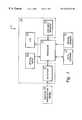
- FIG. 1depicts a block diagram of an illustrative embodiment of a portable electronic device with which the present invention may advantageously be utilized;
- FIG. 2illustrates a more detailed block diagram of a preferred embodiment of inertial sensors 16 of FIG. 1;
- FIG. 3Ais a high level logical flowchart of a method of obtaining position information at the portable electronic device of FIG. 1;
- FIG. 3Bis a high level logical flowchart of a method for presenting position information to a user of the portable electronic device of FIG. 1 .
- Portable electronic device 10can comprise any portable electronic device, including, without limitation, a personal digital assistant (PDA), palmtop computer, mobile telephone, two-way radio, and still or video camera.
- portable electronic device 10can be broadly described as including computational circuitry such as a processor 12 , which is coupled to data storage 14 , inertial sensors 16 , and a number of input/output (I/O) devices 18 .
- Processor 12is a collection of computational circuitry that is preferably (although not necessarily) a general or special purpose processor implemented as an integrated circuit and operable in response to program instructions (e.g., contained within data storage 14 ). In an alternative embodiment, processor 12 can be implemented as logic circuitry that performs the functions described below without the direction of program instructions.
- Data storage 14can be implemented with any one or a combination of data storage technologies appropriate to the type of portable electronic device, including removable storage (e.g., PCMCIA cards, optical and floppy disks, and/or camera film), volatile resident storage (e.g., DRAM), and non-volatile resident storage (e.g., NVRAM and/or hard disk drive).
- removable storagee.g., PCMCIA cards, optical and floppy disks, and/or camera film
- volatile resident storagee.g., DRAM
- non-volatile resident storagee.g., NVRAM and/or hard disk drive
- data storage 14contains storage for a reference position of portable electronic device 10 that may be expressed, for example, in longitude, latitude, and altitude.
- Portable electronic device 10senses its movement in relation to a stored reference position utilizing inertial sensors 16 .
- Inertial sensors 16can be implemented with any technology that permits portable electronic device 10 to itself sense positional changes without directly receiving externally-generated (e.g., GPS) position information.
- One example of such technologyis a piezoelectric gyroscope that detects motion in response to a disturbance in the planar oscillation of a piezoelectric crystal.
- inertial sensors 16is preferred, however, to implement inertial sensors 16 as silicon chip accelerometers, which are commercially available at low cost relative to a GPS receiver.
- silicon chip accelerometeris the ADXL202 produced by Analog Devices of Santa Clara, Calif.
- the I/O devices 18 incorporated within a particular portable electronic device 10will vary depending upon the intended function of the device.
- a PDAfrequently includes a touch screen and stylus for user inputs
- a palmtop computer or mobile telephonetypically receives user inputs via a keyboard or keypad.
- the present inventionis broadly applicable to all portable electronic devices as indicated above, the present invention will hereinafter be described with respect to an illustrative embodiment in which portable electronic device 10 is a still digital camera in order to provide a more particular description of the operation of I/O devices 18 .
- I/O devices 18include a liquid crystal display (LCD) 28 that can display a variety of images, including both text, graphics, and combinations of text and graphics.
- LCD 28preferably displays the image that optical input 22 would capture in response to depression of an image capture (i.e., “shutter release”) button among user input devices 20 .
- digital camera 10also preferably supports a position mode in which position information (e.g., indicative of the global position of digital camera 10 ) is presented within LCD 28 in graphical or textual format and a logging mode in which the current position of digital camera 10 is periodically logged in data storage 14 .
- Digital camera 10may also advantageously display within LCD 28 a menu or similar presentation of textual or graphical (e.g., iconic) selections that may be selected via user input devices 20 in order to identify a desired mode or modes of operation.
- I/O devices 18preferably further include. a data port 24 for communicating a reference position, images, and other data via a wireless (e.g., RF or IR) or wired connection.
- the reference positioncan be provided by a GPS receiver or other position initialization means 26 , which may be located, for example, on board an automobile or at a public site.
- digital camera 10preferably include at least 6 accelerometers, including X+, X ⁇ , Y+, Y ⁇ , Z+, and Z ⁇ accelerometers 16 a - 16 f , respectively. Pairs of accelerometers 16 are equally spaced about an origin point 30 along each of three (imaginary) orthogonal axes (i.e., X axis 32 , Y axis 34 , and Z axis 36 ), and each accelerometer 16 detects acceleration orthogonal to its associated axis in the indicated direction.
- imagingthree orthogonal axes
- X+ and X ⁇ accelerometers 16 a and 16 bdetect acceleration orthogonal to X axis 32 and parallel to Y axis 34
- Y+ and Y ⁇ accelerometers 16 c and 16 ddetect acceleration orthogonal to Y axis 34 and parallel to Z axis 36
- Z+ and Z ⁇ accelerometers 16 e and 16 fdetect acceleration orthogonal to Z axis 36 and parallel to X axis 32 .
- each of accelerometers 16supplies processor 12 with a continuous stream of acceleration data indicative of its measured acceleration.
- processor 12can then compute the velocity, relative orientation, and change in position of digital camera 10 based upon the acceleration data received from accelerometers 16 utilizing basic mathematical relations. For example, if the acceleration measured by X+ accelerometer 16 a is a X+ ,
- v X+ and d X+are the velocity and distance traveled, respectively, of X+ accelerometer 16 a .
- the quantity ⁇ X+can then be integrated once to determine the angular velocity ⁇ X+ and twice to determine the angle of rotation ⁇ X+ as follows:
- ⁇ X⁇ X+ ⁇ X ⁇
- ⁇ Y⁇ Y+ ⁇ Y ⁇
- ⁇ Z⁇ Z+ ⁇ Z ⁇
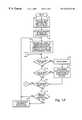
- FIG. 3Athere is illustrated a high level logical flowchart of a method of obtaining position information at a portable electronic device, such as a digital camera, in accordance with the present invention.
- the logical flowchart shown in FIG. 3Ais intended to represent a logical sequence of operations, and it should be apparent that many of the operations can be performed in a different chronological order or in parallel.
- block 42illustrates loading a reference position and reference orientation into data storage 14 of digital camera 10 .
- block 42is performed while digital camera 10 is held stationary at the reference location and in the reference orientation. This can be conveniently accomplished by resting digital camera 10 in a cradle (which can also advantageously serve as a charging stand for the power supply of digital camera 10 ) and automatically inputting the reference position and reference orientation from a GPS receiver or other position initialization means 26 via data port 24 or manually inputting the reference position and reference orientation utilizing user input devices 20 .
- the user of digital camera 10can alternatively manually position and orient digital camera 10 to a known reference position and reference orientation prior to automatically or manually inputting the reference information.
- the reference positionwhich may be expressed as a longitude, latitude and altitude
- a reference orientationwhich may be expressed as a roll, pitch and yaw
- the reference information loaded at block 42may also include a reference time.
- the initialization of digital camera 10continues at block 44 , which depicts processor 12 recording within data storage 14 the stationary output values of each of accelerometers 16 either automatically or in response to a user input. These stationary output values calibrate digital camera 10 and permit processor 12 to thereafter accurately determine the various linear and angular accelerations.
- processor 12may also calculate a current altitude by adding d Y to the reference altitude and a current time by counting a number of clock cycles since the reference time, multiplying the cycle count by the known clock period, and adding the resulting product to the reference time.
- block 48depicts a determination of whether a photograph has been taken, that is, whether the image capture button among user input devices 20 has been depressed. If so, the process passes to block 50 , which illustrates processor 12 recording within data storage 14 the image currently sensed by optical input 22 .
- the captured imageis stored as a JPEG (Joint Photographic Experts Group) file. Of course, for a conventional camera, the image is recorded by selective exposure of photographic film.
- block 51illustrates digital camera 10 logging, in association with the captured image, the current position, orientation, and time at the moment the image was captured.
- This position, orientation, and time together comprise image informationcan either be stored as part of the image (e.g., JPEG) file itself or separately (e.g., in association with a “frame” number).
- the image informationcan be recorded on the photographic film as is conventional for time and date stamps or can be stored separately in other data storage.
- Block 49depicts a determination of whether a logging mode of digital camera 10 is enabled. If the logging mode is enabled, processor 12 periodically logs the current position, orientation and time of digital camera 10 within data storage 14 at default or user-determined intervals, as depicted by the process passing to block 51 . Depending upon implementation, the image information logged at the time of image capture and the log information recorded at periodic intervals can be stored within data storage 14 .either in a single log or in two separate logs.
- Block 52illustrates processor 12 determining whether or not the position mode of digital camera 10 has been selected by the user, for example, via a menu displayed within LCD 28 . If so, the process passes through off-page connector A to on-page connector A of FIG. 3B, which is described below. However, in response to a determination that the position mode of digital camera 10 has not been selected, the process proceeds to block 54 .
- Block 54illustrates a determination of whether or not processor 12 detects the availability of updated reference information. If not, the process simply returns to block 46 , which has been described. If, however, processor 12 detects the availability of updated reference information, which may, for example, be received from a proximate GPS receiver via a wireless transmission or from a user via user input devices 20 , the process proceeds to block 56 . As indicated, block 56 represents processor 12 replacing the appropriate reference information within data storage 14 with the updated reference information. (The replaced reference information, however, can be retained as part of the position log.) The process thereafter returns to block 46 .
- FIG. 3Bthere is depicted a high level logical flowchart of a method by which a portable electronic device can present position and other information in accordance with an illustrative embodiment of the present invention.
- the process shown in FIG. 3Bbegins at on-page connector A in response to a determination at block 52 of FIG. 3A that the position mode of digital camera 10 has been selected.
- a site for which positional information is to be presentedis selected.
- the selection depicted at block 60can be accomplished in numerous ways.
- digital camera 10could be configured to automatically select the site for which reference information is stored within data storage 14 as the default site.
- the usercan be permitted to input positional information for the site via user input devices 20 or to select from among the sites logged at block 51 of FIG. 3 A.
- User selection of a site from among the image capture sitescan be assisted by permitting the user to page through captured images displayed within LCD 28 and/or by displaying for each logged site a textual description of one or more of the longitude, latitude, altitude, roll, pitch, yaw, and time.
- block 60proceeds from block 60 to block 62 , which illustrates digital camera 10 continuing to continuously compute at least its current position and current orientation, and preferably also its current time, in the manner described above with respect to block 46 of FIG. 3 A.
- processor 12 of digital camera 10can then determine the difference between the current position, orientation, and time and those of the selected site, as illustrated at block 64 .
- digital camera 10presents a graphical or audible indication of at least the direction of the selected site relative to the current position.
- processor 12can display within LCD 28 a plan and/or elevation view in which the position of the selected site relative to the current position of digital camera 10 is indicated by an arrow.
- the displayed arrowwould indicate only the direction of the selected site, independent of the current yaw of digital camera 10 .
- This plan viewmay advantageously be combined with a graphical or textual display of the cardinal compass points and the compass direction in which digital camera 10 is pointed.
- the arrowwould represent a projection of the three-dimensional direction in which the selected site lies onto the two-dimensional surface of LCD 28 .
- the direction of the arrow within the elevation viewwould take into account the current orientation (i.e., roll, pitch and yaw) of digital camera 10 .
- the orienteering capabilities of the portable electronic devicecan be further extended by overlaying such plan or elevation views over a corresponding topographical view of the terrain.
- audible outputssuch as synthesized speech can be utilized to indicate the direction of the selected site.
- block 68illustrates a determination of whether or not the user of digital camera 10 has indicated (e.g., by depressing a button among user input devices 20 ) that a new site of interest is to be selected. If so, the process returns to block 60 , which depicts the selection of a new site of interest, and thereafter repeats blocks 62 through 66 .
- a user of digital camera 10is able to retrace a previously travelled path.
- the reference positionas the selected site, the user is able to determine a shortest path from the current position to the reference position.
- Block 70depicts a determination of whether or not the user has requested a return to the photography mode of digital camera 10 . If not, the process returns to block 62 , which has been described. However, if the user has requested a return to the photography mode, the process returns to block 48 of FIG. 3 A.
- the present inventionprovides a method and system that permit a portable electronic device lacking GPS reception capability to obtain and present position, orientation, and other information to a user.
- the portable electronic deviceis initialized with position and other reference information at a reference position. Thereafter, as the portable electronic device is transported, the portable electronic 10 device can determine its current position, orientation, and time based upon the outputs of inertial sensors and the reference information. This current information can then be presented to a user in a variety of formats to assist the user in, among other things, locating the reference position or another selected site.
- Programs defining the functions of the present inventioncan be delivered to the processor via a variety of signal-bearing media, which include, without limitation, non-writable storage media (e.g., CD-ROM), writable storage media (e.g., a floppy diskette or hard disk drive), and communication media, such as computer and telephone networks. It should be understood, therefore, that such signal-bearing media, when carrying or encoding computer readable instructions that direct the functions of the present invention, represent alternative embodiments of the present invention.
- non-writable storage mediae.g., CD-ROM
- writable storage mediae.g., a floppy diskette or hard disk drive
- communication mediasuch as computer and telephone networks.
Landscapes
- Engineering & Computer Science (AREA)
- Radar, Positioning & Navigation (AREA)
- Remote Sensing (AREA)
- Automation & Control Theory (AREA)
- Physics & Mathematics (AREA)
- General Physics & Mathematics (AREA)
- Position Fixing By Use Of Radio Waves (AREA)
Abstract
Description
Claims (28)
Priority Applications (1)
| Application Number | Priority Date | Filing Date | Title |
|---|---|---|---|
| US09/240,926US6542824B1 (en) | 1999-01-29 | 1999-01-29 | Method and system for determining position information utilizing a portable electronic device lacking global positioning system (GPS) reception capability |
Applications Claiming Priority (1)
| Application Number | Priority Date | Filing Date | Title |
|---|---|---|---|
| US09/240,926US6542824B1 (en) | 1999-01-29 | 1999-01-29 | Method and system for determining position information utilizing a portable electronic device lacking global positioning system (GPS) reception capability |
Publications (1)
| Publication Number | Publication Date |
|---|---|
| US6542824B1true US6542824B1 (en) | 2003-04-01 |
Family
ID=22908508
Family Applications (1)
| Application Number | Title | Priority Date | Filing Date |
|---|---|---|---|
| US09/240,926Expired - LifetimeUS6542824B1 (en) | 1999-01-29 | 1999-01-29 | Method and system for determining position information utilizing a portable electronic device lacking global positioning system (GPS) reception capability |
Country Status (1)
| Country | Link |
|---|---|
| US (1) | US6542824B1 (en) |
Cited By (39)
| Publication number | Priority date | Publication date | Assignee | Title |
|---|---|---|---|---|
| US20020080103A1 (en)* | 2000-12-23 | 2002-06-27 | Lg Electronics Inc. | Apparatus and method for displaying image data direction of terminal |
| US20030009394A1 (en)* | 2001-07-06 | 2003-01-09 | International Business Machines Corporation | Method for delivering information based on relative spatial position |
| US20030160867A1 (en)* | 2002-01-17 | 2003-08-28 | Yasunori Ohto | Information providing apparatus, information providing method, storage medium, and computer program |
| US20030174307A1 (en)* | 2002-03-14 | 2003-09-18 | Creo Il. Ltd. | Device and a method of determining an orientation of an image capture apparatus |
| WO2004001337A1 (en)* | 2002-06-24 | 2003-12-31 | Wireless Intellect Labs Pte Ltd | Method and apparatus for improving mobile communication terminal location determination using inertial positioning |
| US20040032970A1 (en)* | 2002-06-06 | 2004-02-19 | Chris Kiraly | Flight parameter measurement system |
| US6721651B1 (en)* | 2002-06-28 | 2004-04-13 | Garmin Ltd. | Rugged, waterproof, navigation device with touch panel |
| US20040212699A1 (en)* | 2000-07-11 | 2004-10-28 | Claus Molgaard | Digital camera with integrated accelerometers |
| US20040236500A1 (en)* | 2003-03-18 | 2004-11-25 | Samsung Electronics Co., Ltd. | Input system based on a three-dimensional inertial navigation system and trajectory estimation method thereof |
| US20050203430A1 (en)* | 2004-03-01 | 2005-09-15 | Lyndsay Williams | Recall device |
| US20060084840A1 (en)* | 2004-10-14 | 2006-04-20 | Hoeg Hans D | Endoscopic imaging with indication of gravity direction |
| US20060170785A1 (en)* | 2002-09-27 | 2006-08-03 | Ken Mashitani | Multiple image transmission method and mobile device having multiple image simultaneous imaging function |
| US20060235765A1 (en)* | 2005-04-15 | 2006-10-19 | David Clifford R | Interactive Image Activation and Distribution System and Associated Methods |
| US20070188798A1 (en)* | 2005-04-15 | 2007-08-16 | David Clifford R | Interactive Image Activation and Distribution System and Associated Methods |
| US20080009310A1 (en)* | 1999-11-03 | 2008-01-10 | Rhoads Geoffrey B | Gestural Techniques with Wireless Mobile Phone Devices |
| US20080239409A1 (en)* | 2007-03-27 | 2008-10-02 | David Clifford R | Interactive Image Activation and Distribution System and Associated Methods |
| US20090201164A1 (en)* | 2008-02-08 | 2009-08-13 | Weksler Arnold S | Techniques for Preventing Damage to a Portable Device |
| US20100056873A1 (en)* | 2008-08-27 | 2010-03-04 | Allen Paul G | Health-related signaling via wearable items |
| US20100174487A1 (en)* | 2004-10-26 | 2010-07-08 | Honeywell International Inc. | Telephone or other portable device with inertial sensor |
| US7845560B2 (en) | 2004-12-14 | 2010-12-07 | Sky-Trax Incorporated | Method and apparatus for determining position and rotational orientation of an object |
| US20100319434A1 (en)* | 2009-06-22 | 2010-12-23 | Research In Motion Limited | Portable electronic device and method of measuring drop impact at the portable electronic device |
| US20110039573A1 (en)* | 2009-08-13 | 2011-02-17 | Qualcomm Incorporated | Accessing positional information for a mobile station using a data code label |
| US20110092260A1 (en)* | 1999-05-12 | 2011-04-21 | Wilbert Quinc Murdock | Method of conducting an interactive computer sport |
| US20110178708A1 (en)* | 2010-01-18 | 2011-07-21 | Qualcomm Incorporated | Using object to align and calibrate inertial navigation system |
| US20120176491A1 (en)* | 2011-01-11 | 2012-07-12 | Qualcomm Incorporated | Camera-based position location and navigation based on image processing |
| JP2012165144A (en)* | 2011-02-04 | 2012-08-30 | Canon Inc | Information processing device and control method therefor |
| US8463654B1 (en) | 2009-05-01 | 2013-06-11 | Clifford R. David | Tour site image capture and marketing system and associated methods |
| EP2608528A1 (en)* | 2011-12-23 | 2013-06-26 | Fluke Corporation | Thermal imaging camera for infrared rephotography |
| US20150160015A1 (en)* | 2013-12-06 | 2015-06-11 | Aro, Inc. | Accurate Mobile Context Detection At Low Sensor Cost |
| US9214032B2 (en) | 2005-04-15 | 2015-12-15 | Freeze Frame, Llc | Interactive guest image capture using video wall/floor/ceiling displays for selections of background scenes, and selection/distribution of customized |
| US9229089B2 (en) | 2010-06-10 | 2016-01-05 | Qualcomm Incorporated | Acquisition of navigation assistance information for a mobile station |
| US9270840B2 (en) | 2011-08-24 | 2016-02-23 | Freeze Frame, Llc | Site image capture and marketing system and associated methods |
| US9270841B2 (en) | 2005-04-15 | 2016-02-23 | Freeze Frame, Llc | Interactive image capture, marketing and distribution |
| CN106643666A (en)* | 2016-09-13 | 2017-05-10 | 首都师范大学 | Moving target detection method and system based on same platform and multiple sensors |
| US9760756B2 (en) | 2013-12-05 | 2017-09-12 | Aro, Inc. | Venue identification using sensor fingerprints |
| US20180139377A1 (en)* | 2015-05-14 | 2018-05-17 | Sri International | Selecting optimal image from mobile device captures |
| US10834335B2 (en) | 2005-04-15 | 2020-11-10 | Freeze Frame, Llc | Interactive guest image capture using video wall/floor/ceiling displays for selections of background scenes, and selection/distribution of customized souvenir portfolios including merged images/sound |
| US12088910B2 (en) | 2017-11-06 | 2024-09-10 | Fluke Corporation | Inspection workflow using object recognition and other techniques |
| US12242916B2 (en) | 2017-11-17 | 2025-03-04 | Divine Logic, Inc. | Systems and methods for tracking items |
Citations (6)
| Publication number | Priority date | Publication date | Assignee | Title |
|---|---|---|---|---|
| US5245537A (en)* | 1991-11-25 | 1993-09-14 | Barber Andrew T | Golf distance tracking, club selection, and player performance statistics apparatus and method |
| US5406489A (en) | 1992-07-10 | 1995-04-11 | Unisys Corporation | Instrument for measuring an aircraft's roll, pitch, and heading by matching position changes along two sets of axes |
| US5617317A (en) | 1995-01-24 | 1997-04-01 | Honeywell Inc. | True north heading estimator utilizing GPS output information and inertial sensor system output information |
| US5774832A (en)* | 1996-04-19 | 1998-06-30 | Honeywell Inc. | Inertial navigation with gravity deflection compensation |
| US5881321A (en)* | 1997-05-09 | 1999-03-09 | Cammotion, Inc.. | Camera motion sensing system |
| US5956660A (en)* | 1997-07-23 | 1999-09-21 | Analogic Corporation | Personal inertial surveying system |
- 1999
- 1999-01-29USUS09/240,926patent/US6542824B1/ennot_activeExpired - Lifetime
Patent Citations (6)
| Publication number | Priority date | Publication date | Assignee | Title |
|---|---|---|---|---|
| US5245537A (en)* | 1991-11-25 | 1993-09-14 | Barber Andrew T | Golf distance tracking, club selection, and player performance statistics apparatus and method |
| US5406489A (en) | 1992-07-10 | 1995-04-11 | Unisys Corporation | Instrument for measuring an aircraft's roll, pitch, and heading by matching position changes along two sets of axes |
| US5617317A (en) | 1995-01-24 | 1997-04-01 | Honeywell Inc. | True north heading estimator utilizing GPS output information and inertial sensor system output information |
| US5774832A (en)* | 1996-04-19 | 1998-06-30 | Honeywell Inc. | Inertial navigation with gravity deflection compensation |
| US5881321A (en)* | 1997-05-09 | 1999-03-09 | Cammotion, Inc.. | Camera motion sensing system |
| US5956660A (en)* | 1997-07-23 | 1999-09-21 | Analogic Corporation | Personal inertial surveying system |
Cited By (87)
| Publication number | Priority date | Publication date | Assignee | Title |
|---|---|---|---|---|
| US20110092260A1 (en)* | 1999-05-12 | 2011-04-21 | Wilbert Quinc Murdock | Method of conducting an interactive computer sport |
| US20080009310A1 (en)* | 1999-11-03 | 2008-01-10 | Rhoads Geoffrey B | Gestural Techniques with Wireless Mobile Phone Devices |
| US8391851B2 (en)* | 1999-11-03 | 2013-03-05 | Digimarc Corporation | Gestural techniques with wireless mobile phone devices |
| US8908053B2 (en)* | 2000-07-11 | 2014-12-09 | Phase One A/S | Digital camera with integrated accelerometers |
| US20100103275A1 (en)* | 2000-07-11 | 2010-04-29 | Phase One A/S | Digital camera with integrated accelerometers |
| US20110205375A1 (en)* | 2000-07-11 | 2011-08-25 | Phase One A/S | Digital camera with integrated accelerometers |
| US8102429B2 (en)* | 2000-07-11 | 2012-01-24 | Phase One A/S | Digital camera with integrated accelerometers |
| US20040212699A1 (en)* | 2000-07-11 | 2004-10-28 | Claus Molgaard | Digital camera with integrated accelerometers |
| US20110205377A1 (en)* | 2000-07-11 | 2011-08-25 | Phase One A/S | Digital camera with integrated accelerometers |
| US20090251565A1 (en)* | 2000-07-11 | 2009-10-08 | Phase One A/S | Digital camera with integrated accelerometers |
| US7554578B2 (en)* | 2000-07-11 | 2009-06-30 | Phase One A/S | Digital camera with integrated accelerometers |
| US8854482B2 (en)* | 2000-07-11 | 2014-10-07 | Phase One A/S | Digital camera with integrated accelerometers |
| US8189058B2 (en)* | 2000-07-11 | 2012-05-29 | Phase One A/S | Digital camera with integrated accelerometers |
| US20120236165A1 (en)* | 2000-07-11 | 2012-09-20 | Phase One A/S | Digital camera with integrated accelerometers |
| US8619146B2 (en)* | 2000-07-11 | 2013-12-31 | Phase One A/S | Digital camera with integrated accelerometers |
| US20020080103A1 (en)* | 2000-12-23 | 2002-06-27 | Lg Electronics Inc. | Apparatus and method for displaying image data direction of terminal |
| US7893955B2 (en)* | 2000-12-23 | 2011-02-22 | Lg Electronics Inc. | Apparatus and method for displaying image data direction of terminal |
| US7324959B2 (en)* | 2001-07-06 | 2008-01-29 | International Business Machines Corporation | Method for delivering information based on relative spatial position |
| US20030009394A1 (en)* | 2001-07-06 | 2003-01-09 | International Business Machines Corporation | Method for delivering information based on relative spatial position |
| US7119831B2 (en)* | 2002-01-17 | 2006-10-10 | Sony Corporation | Information providing apparatus, information providing method, storage medium, and computer program |
| US20030160867A1 (en)* | 2002-01-17 | 2003-08-28 | Yasunori Ohto | Information providing apparatus, information providing method, storage medium, and computer program |
| US20030174307A1 (en)* | 2002-03-14 | 2003-09-18 | Creo Il. Ltd. | Device and a method of determining an orientation of an image capture apparatus |
| US7324663B2 (en)* | 2002-06-06 | 2008-01-29 | Wintriss Engineering Corporation | Flight parameter measurement system |
| US20040032970A1 (en)* | 2002-06-06 | 2004-02-19 | Chris Kiraly | Flight parameter measurement system |
| WO2004001337A1 (en)* | 2002-06-24 | 2003-12-31 | Wireless Intellect Labs Pte Ltd | Method and apparatus for improving mobile communication terminal location determination using inertial positioning |
| US6871138B1 (en)* | 2002-06-28 | 2005-03-22 | Garmin Ltd. | Rugged, waterproof, navigation device with touch panel |
| US6721651B1 (en)* | 2002-06-28 | 2004-04-13 | Garmin Ltd. | Rugged, waterproof, navigation device with touch panel |
| US7518641B2 (en)* | 2002-09-27 | 2009-04-14 | Sanyo Electric Co., Ltd. | Multiple-image transmission method and mobile apparatus having multiple-image simultaneous photographing function |
| US20060170785A1 (en)* | 2002-09-27 | 2006-08-03 | Ken Mashitani | Multiple image transmission method and mobile device having multiple image simultaneous imaging function |
| US20040236500A1 (en)* | 2003-03-18 | 2004-11-25 | Samsung Electronics Co., Ltd. | Input system based on a three-dimensional inertial navigation system and trajectory estimation method thereof |
| US7353112B2 (en)* | 2003-03-18 | 2008-04-01 | Samsung Electronics Co., Ltd. | Input system based on a three-dimensional inertial navigation system and trajectory estimation method thereof |
| US8886298B2 (en) | 2004-03-01 | 2014-11-11 | Microsoft Corporation | Recall device |
| US9918049B2 (en) | 2004-03-01 | 2018-03-13 | Microsoft Technology Licensing, Llc | Recall device |
| US9344688B2 (en) | 2004-03-01 | 2016-05-17 | Microsoft Technology Licensing, Llc | Recall device |
| US20050203430A1 (en)* | 2004-03-01 | 2005-09-15 | Lyndsay Williams | Recall device |
| US7517314B2 (en)* | 2004-10-14 | 2009-04-14 | Karl Storz Development Corp. | Endoscopic imaging with indication of gravity direction |
| US20060084840A1 (en)* | 2004-10-14 | 2006-04-20 | Hoeg Hans D | Endoscopic imaging with indication of gravity direction |
| US20110171946A1 (en)* | 2004-10-26 | 2011-07-14 | Honeywell International Inc. | Mobile telephone with inertial sensor |
| US20100174487A1 (en)* | 2004-10-26 | 2010-07-08 | Honeywell International Inc. | Telephone or other portable device with inertial sensor |
| US8112226B2 (en)* | 2004-10-26 | 2012-02-07 | Honeywell International Inc. | Telephone or other portable device with inertial sensor |
| US7845560B2 (en) | 2004-12-14 | 2010-12-07 | Sky-Trax Incorporated | Method and apparatus for determining position and rotational orientation of an object |
| US20110121068A1 (en)* | 2004-12-14 | 2011-05-26 | Sky-Trax, Inc. | Method and apparatus for determining position and rotational orientation of an object |
| US8196835B2 (en) | 2004-12-14 | 2012-06-12 | Sky-Trax, Inc. | Method and apparatus for determining position and rotational orientation of an object |
| US20060235765A1 (en)* | 2005-04-15 | 2006-10-19 | David Clifford R | Interactive Image Activation and Distribution System and Associated Methods |
| WO2006113392A3 (en)* | 2005-04-15 | 2006-12-14 | Clifford R David | Interactive image activation and distribution system and associated methods |
| US8615443B2 (en) | 2005-04-15 | 2013-12-24 | Clifford R. David | Interactive image activation and distribution system and associated methods |
| US7966223B2 (en) | 2005-04-15 | 2011-06-21 | David Clifford R | Interactive image activation and distribution system and associated methods |
| US9214032B2 (en) | 2005-04-15 | 2015-12-15 | Freeze Frame, Llc | Interactive guest image capture using video wall/floor/ceiling displays for selections of background scenes, and selection/distribution of customized |
| US10834335B2 (en) | 2005-04-15 | 2020-11-10 | Freeze Frame, Llc | Interactive guest image capture using video wall/floor/ceiling displays for selections of background scenes, and selection/distribution of customized souvenir portfolios including merged images/sound |
| US7881968B2 (en) | 2005-04-15 | 2011-02-01 | David Clifford R | Interactive image activation and distribution system and associated methods |
| US9270841B2 (en) | 2005-04-15 | 2016-02-23 | Freeze Frame, Llc | Interactive image capture, marketing and distribution |
| US20110231293A1 (en)* | 2005-04-15 | 2011-09-22 | David Clifford R | Interactive Image Activation And Distribution System And Associated Methods |
| US20070188798A1 (en)* | 2005-04-15 | 2007-08-16 | David Clifford R | Interactive Image Activation and Distribution System and Associated Methods |
| US8635115B2 (en) | 2005-04-15 | 2014-01-21 | Clifford R. David | Interactive image activation and distribution system and associated methods |
| US8260674B2 (en) | 2007-03-27 | 2012-09-04 | David Clifford R | Interactive image activation and distribution system and associate methods |
| US20080239409A1 (en)* | 2007-03-27 | 2008-10-02 | David Clifford R | Interactive Image Activation and Distribution System and Associated Methods |
| US7782201B2 (en)* | 2008-02-08 | 2010-08-24 | Lenovo (Singapore) Pte. Ltd. | Techniques for preventing damage to a portable device |
| US20090201164A1 (en)* | 2008-02-08 | 2009-08-13 | Weksler Arnold S | Techniques for Preventing Damage to a Portable Device |
| US20100056873A1 (en)* | 2008-08-27 | 2010-03-04 | Allen Paul G | Health-related signaling via wearable items |
| US8463654B1 (en) | 2009-05-01 | 2013-06-11 | Clifford R. David | Tour site image capture and marketing system and associated methods |
| US8061182B2 (en)* | 2009-06-22 | 2011-11-22 | Research In Motion Limited | Portable electronic device and method of measuring drop impact at the portable electronic device |
| US20100319434A1 (en)* | 2009-06-22 | 2010-12-23 | Research In Motion Limited | Portable electronic device and method of measuring drop impact at the portable electronic device |
| US20110039573A1 (en)* | 2009-08-13 | 2011-02-17 | Qualcomm Incorporated | Accessing positional information for a mobile station using a data code label |
| US8855929B2 (en)* | 2010-01-18 | 2014-10-07 | Qualcomm Incorporated | Using object to align and calibrate inertial navigation system |
| US20110178708A1 (en)* | 2010-01-18 | 2011-07-21 | Qualcomm Incorporated | Using object to align and calibrate inertial navigation system |
| US9229089B2 (en) | 2010-06-10 | 2016-01-05 | Qualcomm Incorporated | Acquisition of navigation assistance information for a mobile station |
| US9341720B2 (en)* | 2011-01-11 | 2016-05-17 | Qualcomm Incorporated | Camera-based position location and navigation based on image processing |
| CN103282793B (en)* | 2011-01-11 | 2015-11-25 | 高通股份有限公司 | Position location based on camera and the navigation based on image procossing |
| CN103282793A (en)* | 2011-01-11 | 2013-09-04 | 高通股份有限公司 | Camera-based position location and navigation based on image processing |
| US20120176491A1 (en)* | 2011-01-11 | 2012-07-12 | Qualcomm Incorporated | Camera-based position location and navigation based on image processing |
| US9584676B2 (en) | 2011-02-04 | 2017-02-28 | Canon Kabushiki Kaisha | Information processing apparatus and control method therefor |
| JP2012165144A (en)* | 2011-02-04 | 2012-08-30 | Canon Inc | Information processing device and control method therefor |
| US9270840B2 (en) | 2011-08-24 | 2016-02-23 | Freeze Frame, Llc | Site image capture and marketing system and associated methods |
| US20130162835A1 (en)* | 2011-12-23 | 2013-06-27 | Fluke Corporation | Thermal imaging camera for infrared rephotography |
| EP2608528A1 (en)* | 2011-12-23 | 2013-06-26 | Fluke Corporation | Thermal imaging camera for infrared rephotography |
| US9760756B2 (en) | 2013-12-05 | 2017-09-12 | Aro, Inc. | Venue identification using sensor fingerprints |
| US20150160015A1 (en)* | 2013-12-06 | 2015-06-11 | Aro, Inc. | Accurate Mobile Context Detection At Low Sensor Cost |
| US9541652B2 (en)* | 2013-12-06 | 2017-01-10 | Aro, Inc. | Accurate mobile context detection at low sensor cost |
| US20180139377A1 (en)* | 2015-05-14 | 2018-05-17 | Sri International | Selecting optimal image from mobile device captures |
| US10477095B2 (en)* | 2015-05-14 | 2019-11-12 | Sri International | Selecting optimal image from mobile device captures |
| US20190356844A1 (en)* | 2015-05-14 | 2019-11-21 | Sri International | Selecting optimal image from mobile device captures |
| CN106643666A (en)* | 2016-09-13 | 2017-05-10 | 首都师范大学 | Moving target detection method and system based on same platform and multiple sensors |
| WO2018049740A1 (en)* | 2016-09-13 | 2018-03-22 | 首都师范大学 | Moving object detection method and system based on multiple sensors on same platform |
| CN106643666B (en)* | 2016-09-13 | 2019-12-06 | 首都师范大学 | moving object detection method and system based on multiple sensors on same platform |
| US10970857B2 (en) | 2016-09-13 | 2021-04-06 | Capital Normal University | Moving object detection method and system based on multiple sensors on same platform |
| US12088910B2 (en) | 2017-11-06 | 2024-09-10 | Fluke Corporation | Inspection workflow using object recognition and other techniques |
| US12242916B2 (en) | 2017-11-17 | 2025-03-04 | Divine Logic, Inc. | Systems and methods for tracking items |
Similar Documents
| Publication | Publication Date | Title |
|---|---|---|
| US6542824B1 (en) | Method and system for determining position information utilizing a portable electronic device lacking global positioning system (GPS) reception capability | |
| US8514066B2 (en) | Accelerometer based extended display | |
| US10641625B2 (en) | Method and apparatus for calibrating a magnetic sensor | |
| US6195122B1 (en) | Spatial referenced photography | |
| US6845323B1 (en) | GPS device with compass and altimeter and method for displaying navigation information | |
| US8351910B2 (en) | Method and apparatus for determining a user input from inertial sensors | |
| US6862525B1 (en) | GPS device with compass and altimeter and method for displaying navigation information | |
| US6401037B1 (en) | Integrated position and direction system for determining position of offset feature | |
| US6529828B1 (en) | Integrated position and direction system with map display oriented according to heading or direction | |
| US6353798B1 (en) | Integrated position and direction system with three-sensor digital compass | |
| US20080122785A1 (en) | Portable display with improved functionality | |
| EP1801542A2 (en) | Mobile terminal device | |
| US20120050099A1 (en) | Handheld global positioning system device | |
| CN102160017A (en) | Generating virtual buttons using motion sensors | |
| CN102447824B (en) | Image capturing device and method | |
| US6694254B2 (en) | Map display | |
| GB2386488A (en) | Displaying location related information with view of location | |
| US20050222802A1 (en) | Mobile terminal apparatus | |
| US20100145612A1 (en) | Navigation device and method | |
| JP4311447B2 (en) | Azimuth processing device, azimuth processing method, azimuth processing program, azimuth measurement device, tilt offset correction method, azimuth measurement method, azimuth sensor unit, and portable electronic device | |
| Baillie et al. | Rolling, rotating and imagining in a virtual mobile world | |
| US6430505B1 (en) | Automatic charting of obstructions for mission planning | |
| US10006770B2 (en) | Remote location determination system | |
| JP2011247775A (en) | Positional information recorder, imaging apparatus provided with the same and recording method for positional information | |
| US6349263B1 (en) | Integrated position and direction system |
Legal Events
| Date | Code | Title | Description |
|---|---|---|---|
| AS | Assignment | Owner name:INTERNATIONAL BUSINESS MACHINES CORPORATION, NEW Y Free format text:ASSIGNMENT OF ASSIGNORS INTEREST;ASSIGNOR:BERSTIS, VIKTORS;REEL/FRAME:009742/0870 Effective date:19990127 | |
| STCF | Information on status: patent grant | Free format text:PATENTED CASE | |
| CC | Certificate of correction | ||
| FPAY | Fee payment | Year of fee payment:4 | |
| AS | Assignment | Owner name:RIGHT CHANCE, INC., VIRGIN ISLANDS, BRITISH Free format text:ASSIGNMENT OF ASSIGNORS INTEREST;ASSIGNOR:INTERNATIONAL BUSINESS MACHINES CORPORATION;REEL/FRAME:020617/0762 Effective date:20071205 | |
| FPAY | Fee payment | Year of fee payment:8 | |
| AS | Assignment | Owner name:MEDIATEK INC., TAIWAN Free format text:ASSIGNMENT OF ASSIGNORS INTEREST;ASSIGNOR:RIGHT CHANCE INC.;REEL/FRAME:032661/0456 Effective date:20131130 | |
| AS | Assignment | Owner name:MEDIATEK INC., TAIWAN Free format text:ASSIGNMENT OF ASSIGNORS INTEREST;ASSIGNOR:RIGHT CHANCE INC.;REEL/FRAME:032754/0468 Effective date:20131130 | |
| FPAY | Fee payment | Year of fee payment:12 |