US6542657B2 - Binary switch for an optical wavelength router - Google Patents
Binary switch for an optical wavelength routerDownload PDFInfo
- Publication number
- US6542657B2 US6542657B2US09/745,760US74576000AUS6542657B2US 6542657 B2US6542657 B2US 6542657B2US 74576000 AUS74576000 AUS 74576000AUS 6542657 B2US6542657 B2US 6542657B2
- Authority
- US
- United States
- Prior art keywords
- optical
- mirror
- reflection
- fixed
- mirrors
- Prior art date
- Legal status (The legal status is an assumption and is not a legal conclusion. Google has not performed a legal analysis and makes no representation as to the accuracy of the status listed.)
- Expired - Lifetime, expires
Links
- 230000003287optical effectEffects0.000titleclaimsabstractdescription252
- 238000000034methodMethods0.000claimsabstractdescription36
- 239000013307optical fiberSubstances0.000claimsdescription16
- 238000005253claddingMethods0.000claimsdescription11
- 239000002131composite materialSubstances0.000claimsdescription10
- 239000000835fiberSubstances0.000description20
- 239000007787solidSubstances0.000description10
- 230000001902propagating effectEffects0.000description5
- 238000003491arrayMethods0.000description4
- RGNPBRKPHBKNKX-UHFFFAOYSA-NhexaflumuronChemical compoundC1=C(Cl)C(OC(F)(F)C(F)F)=C(Cl)C=C1NC(=O)NC(=O)C1=C(F)C=CC=C1FRGNPBRKPHBKNKX-UHFFFAOYSA-N0.000description4
- 230000003595spectral effectEffects0.000description4
- 230000008901benefitEffects0.000description3
- 238000005516engineering processMethods0.000description3
- 229920000642polymerPolymers0.000description3
- 230000008569processEffects0.000description3
- 230000006833reintegrationEffects0.000description3
- 230000000694effectsEffects0.000description2
- 230000006872improvementEffects0.000description2
- 239000000463materialSubstances0.000description2
- 238000012986modificationMethods0.000description2
- 230000004048modificationEffects0.000description2
- 230000006855networkingEffects0.000description2
- 230000000644propagated effectEffects0.000description2
- VYPSYNLAJGMNEJ-UHFFFAOYSA-NSilicium dioxideChemical compoundO=[Si]=OVYPSYNLAJGMNEJ-UHFFFAOYSA-N0.000description1
- 150000001875compoundsChemical class0.000description1
- 238000010276constructionMethods0.000description1
- 230000007423decreaseEffects0.000description1
- 230000009977dual effectEffects0.000description1
- 238000004880explosionMethods0.000description1
- 239000011521glassSubstances0.000description1
- 239000003365glass fiberSubstances0.000description1
- 230000037361pathwayEffects0.000description1
- 238000005498polishingMethods0.000description1
- 238000000926separation methodMethods0.000description1
- 238000011144upstream manufacturingMethods0.000description1
Images


Classifications
- G—PHYSICS
- G02—OPTICS
- G02B—OPTICAL ELEMENTS, SYSTEMS OR APPARATUS
- G02B6/00—Light guides; Structural details of arrangements comprising light guides and other optical elements, e.g. couplings
- G02B6/24—Coupling light guides
- G02B6/26—Optical coupling means
- G02B6/35—Optical coupling means having switching means
- G02B6/351—Optical coupling means having switching means involving stationary waveguides with moving interposed optical elements
- G02B6/3512—Optical coupling means having switching means involving stationary waveguides with moving interposed optical elements the optical element being reflective, e.g. mirror
- G02B6/352—Optical coupling means having switching means involving stationary waveguides with moving interposed optical elements the optical element being reflective, e.g. mirror the reflective optical element having a shaped reflective surface, e.g. a reflective element comprising several reflective surfaces or facets that function together
- G—PHYSICS
- G02—OPTICS
- G02B—OPTICAL ELEMENTS, SYSTEMS OR APPARATUS
- G02B6/00—Light guides; Structural details of arrangements comprising light guides and other optical elements, e.g. couplings
- G02B6/24—Coupling light guides
- G02B6/26—Optical coupling means
- G02B6/35—Optical coupling means having switching means
- G02B6/354—Switching arrangements, i.e. number of input/output ports and interconnection types
- G02B6/3544—2D constellations, i.e. with switching elements and switched beams located in a plane
- G02B6/3546—NxM switch, i.e. a regular array of switches elements of matrix type constellation
- G—PHYSICS
- G02—OPTICS
- G02B—OPTICAL ELEMENTS, SYSTEMS OR APPARATUS
- G02B6/00—Light guides; Structural details of arrangements comprising light guides and other optical elements, e.g. couplings
- G02B6/24—Coupling light guides
- G02B6/26—Optical coupling means
- G02B6/35—Optical coupling means having switching means
- G02B6/354—Switching arrangements, i.e. number of input/output ports and interconnection types
- G02B6/356—Switching arrangements, i.e. number of input/output ports and interconnection types in an optical cross-connect device, e.g. routing and switching aspects of interconnecting different paths propagating different wavelengths to (re)configure the various input and output links
- G—PHYSICS
- G02—OPTICS
- G02B—OPTICAL ELEMENTS, SYSTEMS OR APPARATUS
- G02B6/00—Light guides; Structural details of arrangements comprising light guides and other optical elements, e.g. couplings
- G02B6/24—Coupling light guides
- G02B6/26—Optical coupling means
- G02B6/35—Optical coupling means having switching means
- G02B6/3564—Mechanical details of the actuation mechanism associated with the moving element or mounting mechanism details
- G02B6/3582—Housing means or package or arranging details of the switching elements, e.g. for thermal isolation
Definitions
- This applicationrelates generally to fiber-optic communications and more specifically to techniques and devices for routing optical signals to different output ports (or, conversely, routing different spectral bands at the output ports to the input port).
- DWDMdense wavelength division multiplexing
- Optical networks designed to operate at the wavelength levelare commonly called “wavelength routing networks” or “optical transport networks” (OTN).
- OTNoptical transport networks
- OTNoptical transport networks
- New types of photonic network elements operating at the wavelength levelare required to perform the cross-connect, ADM and other network switching functions.
- Two of the primary functionsare optical add-drop multiplexers (OADM) and wavelength-selective cross-connects (WSXC).
- the light streamIn order to perform wavelength routing functions optically today, the light stream must first be de-multiplexed or filtered into its many individual wavelengths, each on an individual optical fiber. Then each individual wavelength must be directed toward its target fiber using a large array of optical switches commonly called an optical cross-connect (OXC). Finally, all of the wavelengths must be re-multiplexed before continuing on through the destination fiber.
- OXCoptical cross-connect
- This compound processis complex, very expensive, decreases system reliability and complicates system management.
- the OXCin particular is a technical challenge.
- a typical 40-80 channel DWDM systemwill require thousands of switches to fully cross-connect all the wavelengths.
- Opto-mechanical switcheswhich offer acceptable optical specifications, are too big, expensive and unreliable for widespread deployment. New integrated solid-state technologies based on new materials are being researched, but are still far from commercial application.
- Embodiments of the inventionare directed to an optical routing apparatus for directing two optical signals between two input ports and two output ports.
- Each optical signalfollows a path defined by an optical switching arrangement that is adapted to shift among at least two distinct optical configurations.
- the optical signal provided by the first input portis directed to the first output port and the optical signal provided by the second input port is directed to the second output port.
- the optical signal provided by the second input portis instead directed to the first output port, while the optical signal provided by the first input port is directed to neither output port.
- a variation of a 2 ⁇ 2 optical switchis provided. Improvements in bandwidth over a 2 ⁇ 2 switch are achieved when wavelength-multiplexed optical signals are used.
- the optical switching apparatushas two fixed mirrors and two rotatable mirrors.
- the positions of the two rotatable mirrorsare linked so that the first optical configuration is defined by one position for each rotatable mirror and the second optical configuration is defined by a second position for each rotatable mirror.
- the path of each optical signal of interestincludes a reflection off a fixed mirror and off one of the rotatable mirrors.
- the input and output portsbe spaced at the confocal length of one of the optical signals to improve reintegration of the optical signals at the output ports. Where this confocal length is less than the diameter of the optical fibers used to provide the input and output ports, the optical fibers are preferably flattened, such as by shaving a portion of the fibers' cladding layer.
- the optical switching apparatususes only a single rotatable mirror with four fixed mirrors.
- the rotatable mirrorhas two positions that define the two configurations of the optical switching apparatus.
- the optical signalsare directed so that they are reflected off two of the fixed mirrors and off the rotatable mirror between the fixed-mirror reflections. Accordingly, the rotatable mirror is placed at a focus defined by the arrangement of fixed mirrors.
- the four fixed mirrorsare substituted with a single mirror having a focus where the rotatable mirror is positioned.
- Such a single mirrormay include a composite mirror or may include a curved mirror, such as a portion of a rotated conic section.
- the path lengths of the optical pathwaysare preferably equalized. This is achieved in one embodiment by staggering the input and output ports so that they do not lie in a plane.
- a rotatable mirrorconfigured to have three positions is used with three fixed mirrors to define a 2 ⁇ 2′ optical switch.
- only one of the optical signals provided by the input portsis of interest in any particular configuration.
- the optical signal provided by the first input portis directed to the second output port; when the rotatable mirror is in its second position, the optical signal provided by the first input port is directed to the first output port; and when the rotatable mirror is in its third position, the optical signal provided by the second input port is directed to the second output port.
- the three fixed mirrorsare substituted with a single mirror, which may be composite or curved to define a focus at the position of the rotatable mirror. It is also preferable to equalize path lengths, such as by staggering the input and output ports.
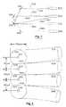
- FIG. 1illustrates schematically a 2 ⁇ 2 optical switch that requires the use of four rotatable micromirrors
- FIG. 2shows the beam shape of an optical signal, illustrating that the beam is narrowest in the confocal region of the beam
- FIG. 3is a schematic representation of optical paths taken for a 2 ⁇ 2′ switch that uses two rotatable micromirrors and two fixed mirrors;
- FIG. 4illustrates how optical fibers are flattened to meet preferred confocal length restrictions on the spacing between input and output ports
- FIG. 5is a schematic representation of optical paths taken for a 2 ⁇ 2′ optical switch that uses a single rotatable micromirror and four fixed mirrors;
- FIG. 6 ( a )is an alternative embodiment to that shown in FIG. 5 where the four fixed mirrors are replaced with a single composite mirror;
- FIG. 6 ( b )is an alternative embodiment to that shown in FIG. 5 where the four fixed mirrors are replaced with a single curved mirror;
- FIG. 7is a particular embodiment of that shown in FIG. 5, in which the input and output ports are not staggered relative to one another;
- FIG. 8is a schematic representation of optical paths taken for a 2 ⁇ 2′ optical switch that uses a single rotatable micromirror and three fixed mirrors;
- FIG. 9 ( a )is an alternative embodiment to that shown in FIG. 8 where the three fixed mirrors are replaced with a single composite mirror;
- FIG. 9 ( b )is an alternative embodiment to that shown in FIG. 8 where the three fixed mirrors are replaced with a single curved mirror.
- Embodiments of the inventioncan be applied to network elements such as optical add-drop multiplexers (OADMs) and wavelength-selective cross-connects (WSXCs), among others, to achieve the goals of optical networking systems.
- OADMsoptical add-drop multiplexers
- WSXCswavelength-selective cross-connects
- optical wavelength routeraccepts light having a plurality of spectral bands at an input port and selectively directs subsets of the spectral bands to desired ones of a plurality of output ports.
- a portis defined by a point where light enters or leaves the optical router.
- the input (or output) portcould be the location of a light source (or detector) or the location of the downstream end of an input fiber (or the upstream end of an output fiber).
- the 2 ⁇ 2′ switchis similar to a “2 ⁇ 2” switch, which is used to direct a pair of signals from two input ports to two output ports.
- a 2 ⁇ 2 switchhas one configuration (“passthrough”) in which the signal from the first (second) input port is directed to the first (second) output port and another configuration (“crossed”) in which the signal from the first (second) input port is directed to the second (first) output port.
- the 2 ⁇ 2 switchis thus configured to propagate a total of four signals. By sacrificing the propagation of one of these four signals in applications where it is unneeded, the 2 ⁇ 2′ switch can achieve corresponding benefits.
- the 2 ⁇ 2′ switchis used as part of an add-drop multiplexer.
- the two input portscorrespond to a “trunk in” and an “add” port;
- the two output portscorrespond to a “trunk out” port and a “drop” port.
- the three routings to be usedare: (1) from the “trunk in” port to the “trunk out” port; (2) from the “trunk in” port to the “drop” port; and (3) from the “add” port to the “trunk out” port.
- the 2 ⁇ 2′ switchmay thus be used to add a signal of wavelength ⁇ 1 and drop a signal of wavelength ⁇ 2 from a trunk line.
- the 2 ⁇ 2 switchmay be implemented with four rotatable microelectromechanical system (“MEMS”) micromirrors. Because the optical signal is demultiplexed into multiple wavelength components, each MEMS micromirror shown in the illustrated configurations may thus denote an array of MEMS micromirrors for acting on each of these individual wavelength components.
- MEMSmicroelectromechanical system
- the switch operationis illustrated for the passthrough configuration with solid lines and for the crossed configuration with dashed lines.
- an optical signal from input port 102is directed along path 132 to output port 108 , being reflected off micromirrors 122 and 128
- an optical signal from input port 104is directed along path 134 to output port 106 , being reflected off micromirrors 124 and 126 .
- All four micromirrors 122 - 128are rotated to the dashed positions when the switch is in the crossed configuration.
- an optical signal from input port 102is directed along path 142 to output port 106 , being reflected off micromirrors 122 and 126 , and an optical signal from input port 104 is directed to output port 108 , being reflected off micromirrors 124 and 128 . It is evident that the switch requires that four micromirrors be precisely rotatable.
- the use of multiple micromirrorsincreases the electromechanical complexity of the switch and limits the potential bandwidth.
- the effect on bandwidthcan be understood by recognizing that the optical beam, rather than propagating with a point cross-section, has a characteristic narrowing shape. This shape is illustrated in FIG. 2, where the beam 220 is propagating along axis 210 .
- the narrow portion of the beam 225is referred to as the “beam waist.”
- the length of the beam waistis defined by the confocal length z c of the beam, which is a measure of the distance along the propagation axis 210 over which the area of the beam first narrows from twice the beam waist 225 size and the expands back to twice its size at the beam waist 225 , i.e. from 2A 0 to A 0 to 2A 0 .
- Bandwidthis related to the movement of each of the wavelength components of the optical signal along a mirror as the signal is modulated. For example, if a particular wavelength component has a spot size of 11 ⁇ m at the focal point and each MEMS micromirror has a diameter of 50 ⁇ m, the available bandwidth is restricted because the modulation cannot be so great that the spot strikes an unintended nearby mirror. When there is more than a single MEMS array, it is impossible to position all of the MEMS arrays at the focal points for all individual wavelength components because of the characteristic beam shape. Accordingly the spot size on the same size mirror is larger, restricting the possible beam modulation even further.
- Maximal bandpathis thus available where the micromirrors are positioned in the confocal zone, and if the spot size is as great as the mirror diameter (i.e. ⁇ 50 ⁇ m in the example), then the available bandwidth is zero. Accordingly, optical signal bandwidth can generally be improved with embodiments in which the number of MEMS micromirror arrays is limited.
- Embodiments of the invention using the 2 ⁇ 2′ switch described belowthus make use of fixed mirrors or reflective surfaces, thereby simultaneously reducing the electromechanical complexity of the switch and permitting increased bandwidth.
- the 2 ⁇ 2′ switchis implemented with only two MEMS micromirrors, as illustrated in FIG. 3 .
- row mirrors 322 and 328are fixed mirrors while mirrors 324 and 326 may each be in one of two positions, indicated by the solid and dashed lines. The paths followed by the optical signals are similarly shown with solid and dashed lines for the two mirror positions used.
- the optical signal from input port 304is directed to output port 306 , reflecting off both MEMS micromirrors 324 and 326 .
- the optical signal from input port 302is simply lost after being reflected from row mirror 322 and MEMS mirror 326 .
- both optical signals from the input ports 302 and 304are directed to output ports 306 and 308 after reflecting off a row mirror and a MEMS mirror.
- the optical signal from input port 302is directed to output port 306 after reflecting off row mirror 322 and MEMS mirror 326 .
- the optical signal from input port 304is directed to output port 308 , being reflected by MEMS mirror 324 and row mirror 328 .
- the “trunk in” signaloriginates at input port 304 and the “trunk out” signal is received at output port 306 ; the add signal originates at input port 302 and the drop signal is received at output port 308 . It is thus evident that this configuration permits addition of a signal of wavelength ⁇ 1 and dropping of a signal of wavelength ⁇ 2 from a trunk line. Addition and dropping of a signal of the same wavelength is prohibited.
- arrays of such 2 ⁇ 2′ switchesare used to direct a plurality of spectral bands.
- the preferred positioning of the mirror arrangementcan be understood with reference to FIG. 4 . Because reintegration of an added signal at an output port requires relatively precise focusing of the signal, it is preferred that the fiber spacing be such that the difference is lengths along the longest and shortest paths be less than the confocal length of the beam, i.e. approximately 80 ⁇ m for signals in the near-infrared (700-1600 nm) primarily used for silica glass fibers. Imposition of this condition limits the spacing between input port 304 and output port 306 to be approximately 80 ⁇ m.
- optical fibersare constructed with a core 312 , 314 , 316 , or 318 surrounded by glass or plastic cladding layer 372 , 374 , 376 , or 378 .
- the coretypically has a diameter of 9, 10, or 11 ⁇ m and is has a higher index of refraction than the cladding layer so that total internal reflection will guide light along the core without loss.
- the standard outside diameter of the cladding layer for telecommunications fibersis 125 ⁇ m.
- the cladding layer for commercially available telecommunications fibersis coated with a 250- ⁇ m-diameter polymer layer (not shown).
- the polymer layeris stripped and the cladding layers of adjacent fibers are shaved as illustrated in FIG. 4 .
- the shavinghas the effect of flattening the fibers so that their cores can be brought sufficiently close to satisfy the confocal-length condition. Accordingly, the shaved edges of the fibers are joined at interfaces 362 , 364 , and 366 in the illustrated embodiment.
- the fiber coresmay be brought sufficiently close together by other techniques, including polishing and material processing.
- the 2 ⁇ 2′ switchis implemented with only a single MEMS micromirror, as illustrated in FIG. 5 .
- four fixed row mirrors 522 , 524 , 526 , and 528are used with a single rotatable MEMS mirror 530 , which may be in one of two positions, indicated by the solid and dashed lines.
- the paths followed by the optical signalsare similarly shown with solid and dashed lines for the two possible positions of the MEMS mirror 530 .
- the optical signal from input port 502is directed to output port 508 , propagating along path 532 so that it is reflected off fixed mirror 522 , MEMS mirror 530 , and fixed mirror 528 .
- the optical signal from input port 504is directed to output port 506 , propagating along path 534 so that it is reflected off fixed mirror 524 , MEMS mirror 530 , and fixed mirror 526 .
- the MEMS mirror 530is instead rotated to its second (dashed) position, the optical signal from input port 502 is propagated along path 536 . It reflects off of fixed mirror 522 and MEMS mirror 530 , whereupon it is simply lost.
- the optical signal from input port 504is directed to output port 508 along path 538 . This path includes reflections off fixed mirror 524 , MEMS mirror 530 , and fixed mirror 528 .
- the “trunk in” signaloriginates at input port 504 and the “trunk out” signal is received at output port 508 .
- the “add” signaloriginates at input port 502 and the “drop” signal is received at output port 506 .
- a signal of wavelength ⁇ 1can be added while a signal of wavelength ⁇ 2 can be dropped, while in the dashed position, the trunk signal is simply directed from “trunk in” to “trunk out.”
- MEMS mirror 530Because only a single MEMS mirror 530 is used, it can be positioned at a focal point of the arrangement of the four fixed mirrors 522 , 524 , 526 , and 528 . This allows not only further improvement in the potential bandwidth when arrays of such configurations are used for a demultiplexed signal, but also relaxes the restriction on spacing the fiber cores at the confocal length. Accordingly, the fibers may be spaced farther apart so that stripping the polymer layer and modifying the cladding layer is unnecessary.
- the fixed mirrorsare shown in FIG. 5 as four discrete fixed mirrors, they may alternatively be replaced with a focusing composite mirror 580 that consists of multiple discrete planar faces (FIG. 6 ( a )) or with a continuous curved mirror 590 (FIG. 6 ( b )).
- the MEMS mirror 530is positioned at the focus of such a mirror.
- the continuous curved mirror 590is a portion of a rotated conic section, i.e. the mirror 590 is spherical, parabolic, elliptical, or hyperbolic.
- the total path length followed by various optical signals for each configuration of the MEMS mirror 530may be different. It is preferable to equalize the total path length for such different optical signals to facilitate reintegration of the optical signals at the output ports.
- One such method for equalizing the path lengthis to stagger the optical fibers leading to the input and/or output ports so that the ends of the ports do not necessarily lie in a plane. Such a method produces the desired equalization and is described in the concurrently filed and commonly assigned application entitled “OPTICAL WAVELENGTH ROUTING ELEMENT WITH STAGGERED FIBERS,” Ser. No. 09/747,064 Dec. 20, 2000, which has been incorporated by reference for all purposes.
- FIG. 7One such embodiment is shown in which input port 504 is spaced a distance d 24 from input port 502 , output port 506 is spaced a distance d 46 from input port 504 , and output port 508 is spaced a distance d 68 from output port 506 .
- the tilt of each of the fixed mirrorsis defined by an angle ⁇ M measured from line L, which is orthogonal to the propagation direction to and from the output and input ports.
- the tilt of the fixed mirrorscan be expressed in terms of the angular deflection 6 of the MEMS mirror between the two configurations:
- ⁇ 52845° ⁇ 1.5 ⁇ .
- d 24531 ⁇ m
- d 46384 ⁇ m
- d 68300 ⁇ m
- ⁇ 52257°
- ⁇ 52449°
- ⁇ 52641°
- ⁇ 52833°
- a 2 ⁇ 2′ optical switchincludes a single three-position MEMS mirror 730 .
- the three-position mirrorhas a rest position denoted by dashes, with two stop positions on either side of the rest position, denoted respectively by a solid line and by dots.
- Three fixed mirrors 722 , 724 , and 726are also provided, each corresponding to one position of the MEMS mirror 730 . For example, when the MEMS mirror 730 is in its rest position (dashed), the optical signal is propagated from input port 702 to output port 706 along path 734 , being reflected off the MEMS mirror 730 and off fixed mirror 724 .
- the optical signal from input port 702is instead directed to output port 708 , propagating along path 732 , which includes reflections off the MEMS mirror 730 and off fixed mirror 726 .
- the other stop position (dotted) of the MEMS mirror 730is used for directing an optical signal from input port 704 to output port 708 .
- the signalpropagates along path 736 , reflecting off fixed mirror 722 , MEMS mirror 730 , and fixed mirror 726 .
- this configurationas a 2 ⁇ 2′ optical switch can be understood by examining its operation as an add/drop multiplexer with the “trunk in” and “add” signals originating respectively at input ports 702 and 704 , and the “drop” and “trunk out” signals being received respectively at output ports 706 and 708 .
- the rest position (dashed) of the MEMS mirror 730permits dropping a signal from the trunk; the first stop position (solid) corresponds to a passthrough of the trunk; and the second stop position (dotted) permits adding a signal to the trunk. Accordingly, it is possible to add a signal with wavelength ⁇ 1 or drop a signal with wavelength ⁇ 2 ( ⁇ 1 ).
- the three fixed mirrorsmay alternatively be replaced with a focusing composite mirror 780 that consists of multiple discrete planar faces (FIG. 9 ( a )) or with a continuous curved mirror 790 (FIG. 9 ( b )).
- the MEMS mirror 730is positioned at the focus of the mirror.
- the continuous curved mirror 790is a portion of a rotated conic section, i.e. the mirror 790 is spherical, parabolic, elliptical, or hyperbolic. It is also preferable that path lengths be equalized. This may be done in one embodiment by staggering the input and output ports as described above.
Landscapes
- Physics & Mathematics (AREA)
- General Physics & Mathematics (AREA)
- Optics & Photonics (AREA)
- Mechanical Light Control Or Optical Switches (AREA)
Abstract
Description
Claims (51)
Priority Applications (3)
| Application Number | Priority Date | Filing Date | Title |
|---|---|---|---|
| US09/745,760US6542657B2 (en) | 2000-12-20 | 2000-12-20 | Binary switch for an optical wavelength router |
| PCT/US2001/050524WO2002050588A1 (en) | 2000-12-20 | 2001-12-20 | Binary switch for an optical wavelength router |
| AU2002232870AAU2002232870A1 (en) | 2000-12-20 | 2001-12-20 | Binary switch for an optical wavelength router |
Applications Claiming Priority (1)
| Application Number | Priority Date | Filing Date | Title |
|---|---|---|---|
| US09/745,760US6542657B2 (en) | 2000-12-20 | 2000-12-20 | Binary switch for an optical wavelength router |
Publications (2)
| Publication Number | Publication Date |
|---|---|
| US20020076137A1 US20020076137A1 (en) | 2002-06-20 |
| US6542657B2true US6542657B2 (en) | 2003-04-01 |
Family
ID=24998139
Family Applications (1)
| Application Number | Title | Priority Date | Filing Date |
|---|---|---|---|
| US09/745,760Expired - LifetimeUS6542657B2 (en) | 2000-12-20 | 2000-12-20 | Binary switch for an optical wavelength router |
Country Status (3)
| Country | Link |
|---|---|
| US (1) | US6542657B2 (en) |
| AU (1) | AU2002232870A1 (en) |
| WO (1) | WO2002050588A1 (en) |
Cited By (25)
| Publication number | Priority date | Publication date | Assignee | Title |
|---|---|---|---|---|
| US20030090762A1 (en)* | 2001-09-28 | 2003-05-15 | Mcguire James P. | Littrow grating based oadm |
| US20030142899A1 (en)* | 2002-01-25 | 2003-07-31 | Mitsubishi Denki Kabushiki Kaisha | Optical signal switching unit |
| US20030215179A1 (en)* | 2001-03-30 | 2003-11-20 | Mcguire James P. | Programmable optical add/drop multiplexer |
| US20040013349A1 (en)* | 2002-07-18 | 2004-01-22 | Shanti Bhattacharya | Method and apparatus for optical switching with same side input and outputs |
| US20040033010A1 (en)* | 2002-06-12 | 2004-02-19 | Mcguire James P. | Wavelength selective optical switch |
| US20040136718A1 (en)* | 2002-07-23 | 2004-07-15 | Mcguire James P. | East-West separable ROADM |
| US6766073B1 (en)* | 2002-05-17 | 2004-07-20 | The Ohio State University | Optical circulator with large number of ports and no polarization-based components |
| US20050041914A1 (en)* | 2000-12-20 | 2005-02-24 | Robert Anderson | Wavelength router with staggered input/output fibers |
| US20050157971A1 (en)* | 2002-05-17 | 2005-07-21 | Rene Juijve | Apparatus comprising an optical input device and at least one further optical device having a common radiation source |
| US6937784B1 (en)* | 2002-12-23 | 2005-08-30 | Lockheed Martin Corporation | Method and apparatus for MEMS optical switching using rotating mirrors |
| US20060088242A1 (en)* | 2003-12-31 | 2006-04-27 | Vlad Novotny | Optical switches with uniaxial mirrors |
| US20060127009A1 (en)* | 2004-12-10 | 2006-06-15 | Mahmoud Rasras | Waveguide turn for a waveguide circuit |
| US20090028502A1 (en)* | 2006-11-07 | 2009-01-29 | Harry Wayne Presley | Segmented prism element and associated methods for manifold fiberoptic switches |
| US20090103861A1 (en)* | 2006-11-07 | 2009-04-23 | Olympus Microsystems America, Inc. | Beam steering element and associated methods for manifold fiberoptic switches |
| US20090110349A1 (en)* | 2006-11-07 | 2009-04-30 | Olympus Microsystems America, Inc | Beam steering element and associated methods for mixed manifold fiberoptic switches |
| US20090220192A1 (en)* | 2008-02-28 | 2009-09-03 | Olympus Corporation | Wavelength selective switch with reduced chromatic dispersion and polarization-dependent loss |
| US20090231580A1 (en)* | 2006-11-07 | 2009-09-17 | Olympus Corporation | Beam steering element and associated methods for manifold fiberoptic switches and monitoring |
| US20090232446A1 (en)* | 2006-11-07 | 2009-09-17 | Olympus Corporation | High port count instantiated wavelength selective switch |
| US20090304328A1 (en)* | 2006-11-07 | 2009-12-10 | Olympus Microsystems America, Inc. | Beam steering element and associated methods for manifold fiberoptic switches and monitoring |
| US20100192941A1 (en)* | 2009-01-30 | 2010-08-05 | Stoia Michael F | Solar Concentration System With Micro-Mirror Array |
| US9813022B2 (en) | 2014-02-21 | 2017-11-07 | The Boeing Company | Dynamically setting a threshold output level for a solar array |
| US10236822B2 (en) | 2014-02-21 | 2019-03-19 | The Boeing Company | Method and apparatus for calibrating a micro-concentrator solar array |
| US10250182B2 (en) | 2014-02-21 | 2019-04-02 | The Boeing Company | Micro-concentrator solar array using micro-electromechanical systems (MEMS) based reflectors |
| US20190327015A1 (en)* | 2016-12-27 | 2019-10-24 | Xieon Networks S.À.R.L. | Wavelength selective switch and reconfigurable optical add/drop multiplexer |
| US10693028B2 (en) | 2014-02-21 | 2020-06-23 | The Boeing Company | Micro-concentrator solar array using micro-electromechanical systems (MEMS) based reflectors |
Families Citing this family (12)
| Publication number | Priority date | Publication date | Assignee | Title |
|---|---|---|---|---|
| US6407851B1 (en) | 2000-08-01 | 2002-06-18 | Mohammed N. Islam | Micromechanical optical switch |
| US6795605B1 (en) | 2000-08-01 | 2004-09-21 | Cheetah Omni, Llc | Micromechanical optical switch |
| US6445502B1 (en) | 2001-02-02 | 2002-09-03 | Celeste Optics, Inc. | Variable blazed grating |
| US6721473B1 (en) | 2001-02-02 | 2004-04-13 | Cheetah Omni, Llc | Variable blazed grating based signal processing |
| US7145704B1 (en) | 2003-11-25 | 2006-12-05 | Cheetah Omni, Llc | Optical logic gate based optical router |
| US7339714B1 (en) | 2001-02-02 | 2008-03-04 | Cheetah Omni, Llc | Variable blazed grating based signal processing |
| US6549695B2 (en)* | 2001-06-05 | 2003-04-15 | Marconi Communications, Inc. | Method and apparatus for optically switching data |
| US6842556B2 (en)* | 2002-09-10 | 2005-01-11 | Analog Devices, Inc. | Two input, two output optical switch using two movable mirrors |
| FR2876802B1 (en)* | 2004-10-19 | 2007-01-19 | Pellenc Selective Technologie | OPTICAL MULTIPLEXING DEVICE |
| US7429983B2 (en) | 2005-11-01 | 2008-09-30 | Cheetah Omni, Llc | Packet-based digital display system |
| US7341383B2 (en)* | 2006-08-01 | 2008-03-11 | Adc Telecommunications, Inc. | Dual inner diameter ferrule device and method |
| US12013577B2 (en) | 2011-10-10 | 2024-06-18 | Commscope Technologies Llc | Cable and dual inner diameter ferrule device with smooth internal contours and method |
Citations (12)
| Publication number | Priority date | Publication date | Assignee | Title |
|---|---|---|---|---|
| US5414540A (en) | 1993-06-01 | 1995-05-09 | Bell Communications Research, Inc. | Frequency-selective optical switch employing a frequency dispersive element, polarization dispersive element and polarization modulating elements |
| US5917625A (en) | 1993-09-09 | 1999-06-29 | Kabushiki Kaisha Toshiba | High resolution optical multiplexing and demultiplexing device in optical communication system |
| US5960133A (en) | 1998-01-27 | 1999-09-28 | Tellium, Inc. | Wavelength-selective optical add/drop using tilting micro-mirrors |
| US5999672A (en) | 1997-12-13 | 1999-12-07 | Light Chip, Inc. | Integrated bi-directional dual axial gradient refractive index/diffraction grating wavelength division multiplexer |
| US6097859A (en)* | 1998-02-12 | 2000-08-01 | The Regents Of The University Of California | Multi-wavelength cross-connect optical switch |
| US6097519A (en) | 1996-08-01 | 2000-08-01 | Lucent Technologies Inc. | Fiber optic network using space and wavelength multiplexed data channel arrays |
| US6108471A (en) | 1998-11-17 | 2000-08-22 | Bayspec, Inc. | Compact double-pass wavelength multiplexer-demultiplexer having an increased number of channels |
| US6253001B1 (en)* | 2000-01-20 | 2001-06-26 | Agilent Technologies, Inc. | Optical switches using dual axis micromirrors |
| US6307657B1 (en) | 1998-07-17 | 2001-10-23 | Lucent Technologies Inc. | Optomechanical platform |
| US6330102B1 (en)* | 2000-03-24 | 2001-12-11 | Onix Microsystems | Apparatus and method for 2-dimensional steered-beam NxM optical switch using single-axis mirror arrays and relay optics |
| US6337760B1 (en)* | 2000-07-17 | 2002-01-08 | Reflectivity, Inc. | Encapsulated multi-directional light beam steering device |
| US6501877B1 (en) | 1999-11-16 | 2002-12-31 | Network Photonics, Inc. | Wavelength router |
- 2000
- 2000-12-20USUS09/745,760patent/US6542657B2/ennot_activeExpired - Lifetime
- 2001
- 2001-12-20WOPCT/US2001/050524patent/WO2002050588A1/ennot_activeApplication Discontinuation
- 2001-12-20AUAU2002232870Apatent/AU2002232870A1/ennot_activeAbandoned
Patent Citations (12)
| Publication number | Priority date | Publication date | Assignee | Title |
|---|---|---|---|---|
| US5414540A (en) | 1993-06-01 | 1995-05-09 | Bell Communications Research, Inc. | Frequency-selective optical switch employing a frequency dispersive element, polarization dispersive element and polarization modulating elements |
| US5917625A (en) | 1993-09-09 | 1999-06-29 | Kabushiki Kaisha Toshiba | High resolution optical multiplexing and demultiplexing device in optical communication system |
| US6097519A (en) | 1996-08-01 | 2000-08-01 | Lucent Technologies Inc. | Fiber optic network using space and wavelength multiplexed data channel arrays |
| US5999672A (en) | 1997-12-13 | 1999-12-07 | Light Chip, Inc. | Integrated bi-directional dual axial gradient refractive index/diffraction grating wavelength division multiplexer |
| US5960133A (en) | 1998-01-27 | 1999-09-28 | Tellium, Inc. | Wavelength-selective optical add/drop using tilting micro-mirrors |
| US6097859A (en)* | 1998-02-12 | 2000-08-01 | The Regents Of The University Of California | Multi-wavelength cross-connect optical switch |
| US6307657B1 (en) | 1998-07-17 | 2001-10-23 | Lucent Technologies Inc. | Optomechanical platform |
| US6108471A (en) | 1998-11-17 | 2000-08-22 | Bayspec, Inc. | Compact double-pass wavelength multiplexer-demultiplexer having an increased number of channels |
| US6501877B1 (en) | 1999-11-16 | 2002-12-31 | Network Photonics, Inc. | Wavelength router |
| US6253001B1 (en)* | 2000-01-20 | 2001-06-26 | Agilent Technologies, Inc. | Optical switches using dual axis micromirrors |
| US6330102B1 (en)* | 2000-03-24 | 2001-12-11 | Onix Microsystems | Apparatus and method for 2-dimensional steered-beam NxM optical switch using single-axis mirror arrays and relay optics |
| US6337760B1 (en)* | 2000-07-17 | 2002-01-08 | Reflectivity, Inc. | Encapsulated multi-directional light beam steering device |
Non-Patent Citations (6)
| Title |
|---|
| Ford et al., "Wavelength Add-Drop Switching Using Tilting Micromirrors," Journal of Lightwave Technology, vol. 17, No. 5, May 1999, pp. 904-911. |
| Grade, John D. et al., "A Large-Deflection Electrostatic Actuator For Optical Switching Applications," Solid-State and Actuaotr Workshop, Hilton Head Island, SC, pp. 97-100 (Jun. 2000). |
| Philippe et al., "Wavelength demultiplexer: using echelette gratings on silicon substrate," Applied Optics, vol. 24, No. 7, Apr. 1985, pp. 1006-1011. |
| Piezo Systems, Inc. Catalog #2, 1998, pp. 1, 30-45. |
| Rallison, R.D., "Dense Wavelength Division Multiplexing (DWDM) and the Dickson Grating," White Paper, Jan. 6, 2001. |
| Sun, et al., "Demultiplexer with 120 Channels and 0.29-nm Channel Spacing," IEEE Photonics Technology Letters, vol. 10, No. 1, Jan. 1998, pp. 90-92. |
Cited By (47)
| Publication number | Priority date | Publication date | Assignee | Title |
|---|---|---|---|---|
| US6873755B2 (en)* | 2000-12-20 | 2005-03-29 | Pts Corporation | Wavelength router with staggered input/output fibers |
| US20050041914A1 (en)* | 2000-12-20 | 2005-02-24 | Robert Anderson | Wavelength router with staggered input/output fibers |
| US20030215179A1 (en)* | 2001-03-30 | 2003-11-20 | Mcguire James P. | Programmable optical add/drop multiplexer |
| US7177493B2 (en) | 2001-03-30 | 2007-02-13 | Optical Research Associates | Programmable optical add/drop multiplexer |
| US20030090762A1 (en)* | 2001-09-28 | 2003-05-15 | Mcguire James P. | Littrow grating based oadm |
| US7203421B2 (en) | 2001-09-28 | 2007-04-10 | Optical Research Associates | Littrow grating based OADM |
| US20030142899A1 (en)* | 2002-01-25 | 2003-07-31 | Mitsubishi Denki Kabushiki Kaisha | Optical signal switching unit |
| US6826325B2 (en)* | 2002-01-25 | 2004-11-30 | Mitsubishi Denki Kabushiki Kaisha | Optical signal switching unit |
| US6766073B1 (en)* | 2002-05-17 | 2004-07-20 | The Ohio State University | Optical circulator with large number of ports and no polarization-based components |
| US20050157971A1 (en)* | 2002-05-17 | 2005-07-21 | Rene Juijve | Apparatus comprising an optical input device and at least one further optical device having a common radiation source |
| US7330615B2 (en) | 2002-06-12 | 2008-02-12 | Optical Research Associates | Wavelength selective optical switch |
| US20040033010A1 (en)* | 2002-06-12 | 2004-02-19 | Mcguire James P. | Wavelength selective optical switch |
| US20080205821A1 (en)* | 2002-06-12 | 2008-08-28 | Optical Research Associates | Wavelength selective optical switch |
| US20070104418A1 (en)* | 2002-06-12 | 2007-05-10 | Mcguire James P Jr | Wavelength selective optical switch |
| US7519247B2 (en) | 2002-06-12 | 2009-04-14 | Optical Research Associates | Wavelength selective optical switch |
| US7058251B2 (en) | 2002-06-12 | 2006-06-06 | Optical Research Associates | Wavelength selective optical switch |
| US20060182387A1 (en)* | 2002-06-12 | 2006-08-17 | Mcguire James P Jr | Wavelength selective optical switch |
| US20040013349A1 (en)* | 2002-07-18 | 2004-01-22 | Shanti Bhattacharya | Method and apparatus for optical switching with same side input and outputs |
| US6842555B2 (en)* | 2002-07-18 | 2005-01-11 | Analog Devices, Inc. | Method and apparatus for optical switching with same side input and outputs |
| US20040136718A1 (en)* | 2002-07-23 | 2004-07-15 | Mcguire James P. | East-West separable ROADM |
| US6941073B2 (en) | 2002-07-23 | 2005-09-06 | Optical Research Associates | East-west separable ROADM |
| US6937784B1 (en)* | 2002-12-23 | 2005-08-30 | Lockheed Martin Corporation | Method and apparatus for MEMS optical switching using rotating mirrors |
| US20060088242A1 (en)* | 2003-12-31 | 2006-04-27 | Vlad Novotny | Optical switches with uniaxial mirrors |
| US20060127009A1 (en)* | 2004-12-10 | 2006-06-15 | Mahmoud Rasras | Waveguide turn for a waveguide circuit |
| US7164824B2 (en)* | 2004-12-10 | 2007-01-16 | Lucent Technologies Inc. | Waveguide turn for a waveguide circuit |
| US8000568B2 (en) | 2006-11-07 | 2011-08-16 | Olympus Corporation | Beam steering element and associated methods for mixed manifold fiberoptic switches |
| US7769255B2 (en) | 2006-11-07 | 2010-08-03 | Olympus Corporation | High port count instantiated wavelength selective switch |
| US20090110349A1 (en)* | 2006-11-07 | 2009-04-30 | Olympus Microsystems America, Inc | Beam steering element and associated methods for mixed manifold fiberoptic switches |
| US8131123B2 (en) | 2006-11-07 | 2012-03-06 | Olympus Corporation | Beam steering element and associated methods for manifold fiberoptic switches and monitoring |
| US20090028502A1 (en)* | 2006-11-07 | 2009-01-29 | Harry Wayne Presley | Segmented prism element and associated methods for manifold fiberoptic switches |
| US20090231580A1 (en)* | 2006-11-07 | 2009-09-17 | Olympus Corporation | Beam steering element and associated methods for manifold fiberoptic switches and monitoring |
| US20090232446A1 (en)* | 2006-11-07 | 2009-09-17 | Olympus Corporation | High port count instantiated wavelength selective switch |
| US20090304328A1 (en)* | 2006-11-07 | 2009-12-10 | Olympus Microsystems America, Inc. | Beam steering element and associated methods for manifold fiberoptic switches and monitoring |
| US7702194B2 (en) | 2006-11-07 | 2010-04-20 | Olympus Corporation | Beam steering element and associated methods for manifold fiberoptic switches |
| US7720329B2 (en) | 2006-11-07 | 2010-05-18 | Olympus Corporation | Segmented prism element and associated methods for manifold fiberoptic switches |
| US7873246B2 (en) | 2006-11-07 | 2011-01-18 | Olympus Corporation | Beam steering element and associated methods for manifold fiberoptic switches and monitoring |
| US20090103861A1 (en)* | 2006-11-07 | 2009-04-23 | Olympus Microsystems America, Inc. | Beam steering element and associated methods for manifold fiberoptic switches |
| US8190025B2 (en) | 2008-02-28 | 2012-05-29 | Olympus Corporation | Wavelength selective switch having distinct planes of operation |
| US20090220233A1 (en)* | 2008-02-28 | 2009-09-03 | Olympus Corporation | Wavelength selective switch having distinct planes of operation |
| US20090220192A1 (en)* | 2008-02-28 | 2009-09-03 | Olympus Corporation | Wavelength selective switch with reduced chromatic dispersion and polarization-dependent loss |
| US20100192941A1 (en)* | 2009-01-30 | 2010-08-05 | Stoia Michael F | Solar Concentration System With Micro-Mirror Array |
| US9813022B2 (en) | 2014-02-21 | 2017-11-07 | The Boeing Company | Dynamically setting a threshold output level for a solar array |
| US10236822B2 (en) | 2014-02-21 | 2019-03-19 | The Boeing Company | Method and apparatus for calibrating a micro-concentrator solar array |
| US10250182B2 (en) | 2014-02-21 | 2019-04-02 | The Boeing Company | Micro-concentrator solar array using micro-electromechanical systems (MEMS) based reflectors |
| US10693028B2 (en) | 2014-02-21 | 2020-06-23 | The Boeing Company | Micro-concentrator solar array using micro-electromechanical systems (MEMS) based reflectors |
| US20190327015A1 (en)* | 2016-12-27 | 2019-10-24 | Xieon Networks S.À.R.L. | Wavelength selective switch and reconfigurable optical add/drop multiplexer |
| US10862611B2 (en)* | 2016-12-27 | 2020-12-08 | Xieon Networks S.A.R.L. | Wavelength selective switch and reconfigurable optical add/drop multiplexer |
Also Published As
| Publication number | Publication date |
|---|---|
| WO2002050588A1 (en) | 2002-06-27 |
| WO2002050588B1 (en) | 2002-09-12 |
| AU2002232870A1 (en) | 2002-07-01 |
| US20020076137A1 (en) | 2002-06-20 |
Similar Documents
| Publication | Publication Date | Title |
|---|---|---|
| US6542657B2 (en) | Binary switch for an optical wavelength router | |
| US6535664B1 (en) | 1×2 optical wavelength router | |
| US6535319B2 (en) | Free-space optical wavelength routing element based on stepwise controlled tilting mirrors | |
| US8693821B2 (en) | Bidirectional wavelength cross connect architectures using wavelength routing elements | |
| EP1606661A1 (en) | Optical wavelength division multiplexer/ demultiplexer device | |
| US20090297097A1 (en) | Reconfigurable optical switch | |
| US6192174B1 (en) | Wavelength selection switches for optical application | |
| US20050025426A1 (en) | Planar lightwave wavelength blocker devices using micromachines | |
| US6845187B1 (en) | Linear optical beam translator for optical routing | |
| US7177498B2 (en) | Two-by-two optical routing element using two-position MEMS mirrors | |
| US6798951B2 (en) | Wavelength router with a transmissive dispersive element | |
| EP1463372B1 (en) | Optical routing mechanism with integrated fiber input/output arrangement on a MEMS die | |
| US6873755B2 (en) | Wavelength router with staggered input/output fibers | |
| US20040105619A1 (en) | Focal length dispersion compensation for field curvature | |
| US6781730B2 (en) | Variable wavelength attenuator for spectral grooming and dynamic channel equalization using micromirror routing | |
| US20030174958A1 (en) | One-to-M wavelength routing element | |
| US7106924B2 (en) | Optical switching device and optical transmission system |
Legal Events
| Date | Code | Title | Description |
|---|---|---|---|
| AS | Assignment | Owner name:NETWORK PHOTONICS, INC., COLORADO Free format text:ASSIGNMENT OF ASSIGNORS INTEREST;ASSIGNOR:ANDERSON, ROBERT;REEL/FRAME:011443/0733 Effective date:20001218 | |
| AS | Assignment | Owner name:VENTURE LENDING & LEASING III, INC., AS AGENT, CAL Free format text:SECURITY INTEREST;ASSIGNOR:NETWORK PHOTONICS, INC.;REEL/FRAME:012086/0840 Effective date:20010709 | |
| STCF | Information on status: patent grant | Free format text:PATENTED CASE | |
| AS | Assignment | Owner name:PTS CORPORATION, A DELAWARE CORPORATION, CALIFORNI Free format text:ASSIGNMENT OF ASSIGNORS INTEREST;ASSIGNOR:NETWORK PHOTONICS, INC.;REEL/FRAME:013828/0575 Effective date:20030617 | |
| FEPP | Fee payment procedure | Free format text:PAT HOLDER NO LONGER CLAIMS SMALL ENTITY STATUS, ENTITY STATUS SET TO UNDISCOUNTED (ORIGINAL EVENT CODE: STOL); ENTITY STATUS OF PATENT OWNER: LARGE ENTITY | |
| REFU | Refund | Free format text:REFUND - SURCHARGE, PETITION TO ACCEPT PYMT AFTER EXP, UNINTENTIONAL (ORIGINAL EVENT CODE: R2551); ENTITY STATUS OF PATENT OWNER: LARGE ENTITY | |
| AS | Assignment | Owner name:PTS CORPORATION, CALIFORNIA Free format text:ASSIGNMENT OF ASSIGNORS INTEREST;ASSIGNOR:NETWORK PHOTONICS, INC.;REEL/FRAME:017846/0787 Effective date:20030617 | |
| AS | Assignment | Owner name:ALTERA CORPORATION, CALIFORNIA Free format text:ASSIGNMENT OF ASSIGNORS INTEREST;ASSIGNOR:PTS CORPORATION;REEL/FRAME:018720/0569 Effective date:20060710 | |
| FPAY | Fee payment | Year of fee payment:4 | |
| AS | Assignment | Owner name:PTS CORPORATION, CALIFORNIA Free format text:CORRECTED COVER SHEET TO CORRECT PROPERTY NUMBER, PREVIOUSLY RECORDED AT REEL/FRAME 013828/0575 (ASSIGNMENT OF ASSIGNOR'S INTEREST);ASSIGNOR:NETWORK PHOTONICS, INC.;REEL/FRAME:018385/0457 Effective date:20030617 | |
| FPAY | Fee payment | Year of fee payment:8 | |
| FPAY | Fee payment | Year of fee payment:12 |