US6542358B1 - Retractable platform with wireless electrical interface - Google Patents
Retractable platform with wireless electrical interfaceDownload PDFInfo
- Publication number
- US6542358B1 US6542358B1US09/703,203US70320300AUS6542358B1US 6542358 B1US6542358 B1US 6542358B1US 70320300 AUS70320300 AUS 70320300AUS 6542358 B1US6542358 B1US 6542358B1
- Authority
- US
- United States
- Prior art keywords
- retractable platform
- communication
- card
- platform
- retractable
- Prior art date
- Legal status (The legal status is an assumption and is not a legal conclusion. Google has not performed a legal analysis and makes no representation as to the accuracy of the status listed.)
- Expired - Fee Related, expires
Links
Images


Classifications
- H—ELECTRICITY
- H05—ELECTRIC TECHNIQUES NOT OTHERWISE PROVIDED FOR
- H05K—PRINTED CIRCUITS; CASINGS OR CONSTRUCTIONAL DETAILS OF ELECTRIC APPARATUS; MANUFACTURE OF ASSEMBLAGES OF ELECTRICAL COMPONENTS
- H05K5/00—Casings, cabinets or drawers for electric apparatus
- H05K5/02—Details
- H05K5/0256—Details of interchangeable modules or receptacles therefor, e.g. cartridge mechanisms
- H05K5/026—Details of interchangeable modules or receptacles therefor, e.g. cartridge mechanisms having standardized interfaces
- H05K5/0265—Details of interchangeable modules or receptacles therefor, e.g. cartridge mechanisms having standardized interfaces of PCMCIA type
- H05K5/0273—Details of interchangeable modules or receptacles therefor, e.g. cartridge mechanisms having standardized interfaces of PCMCIA type having extensions for peripherals, e.g. LAN, antennas
- G—PHYSICS
- G06—COMPUTING OR CALCULATING; COUNTING
- G06F—ELECTRIC DIGITAL DATA PROCESSING
- G06F1/00—Details not covered by groups G06F3/00 - G06F13/00 and G06F21/00
- G06F1/16—Constructional details or arrangements
- G06F1/1613—Constructional details or arrangements for portable computers
- G06F1/1632—External expansion units, e.g. docking stations
Definitions
- the present inventiongenerally relates to a retractable platform that is connectable to an electronic device. More particularly, the present invention relates to a retractable platform that includes a wireless or non-mechanical electrical interface that allows electrical communication to be established with an electronic device.
- a laptop computeris generally portable and it can be connected to a network or communication system from a wide variety of places to send and/or receive information and data.
- a conventional laptop computercan be configured to be connected to a local area network (LAN), wide area network (WAN), wireless communication network, telephone network or the Internet from practically any location.
- LANlocal area network
- WANwide area network
- wireless communication networktelephone network or the Internet
- expansion cardscan significantly increase the capabilities of the computer by providing added features and/or capabilities.
- known expansion cardsare often configured to function as memory cards, communication cards, network interface cards, sound cards, modems, or other devices supplying add-on functionality.
- these expansion cardsallow the user to customize the features and capabilities of the computer as desired by the user.
- these expansion cardsare often configured according to guidelines or standards that are known in the industry to promote compatibility and interchangeability.
- PCMCIAPersonal Computer Memory Card International Association
- PCMCIAPersonal Computer Memory Card International Association
- PC cardsExpansion cards that comply with the PCMCIA standards are common referred to as “PC cards.”
- PCMCIA guidelinesset forth specific standards for Type I PC cards, Type II PC cards and Type III PC cards.
- Each of these PC card typeshas a length of 85.6 mm and a width of 54.0 mm, but the height varies according to the type of card.
- a Type I PC cardshas a height up to 3.3 mm
- a type II PC cardhas a height up to 5.0 mm
- a Type III PC cardhas a height up to 10.5 mm.
- PC cardscan combine several of these features on a single card to provide added functionality, and these types of cards are commonly referred to as “combination cards” or “combo cards.”
- a combination cardmay combine modem and network interface functionality so that a user can use the same card to connect to a LAN, WAN or the Internet. These combination cards may allow the user to perform these additional features or capabilities simultaneously or independently.
- PC cardshave become very popular because of their relatively small size, interchangeability, and capability.
- the industryhas also developed a new generation of expansion devices with an even smaller physical size or “form factor” than that of PC cards.
- the new expansion devices, or cardsare commonly referred to as “compact flash” or “miniature flash” cards.
- a typical compact flash cardhas a length of 36 mm and a width of 43 mm, which requires about 1550 mm 2 of space.
- a PC card with a length of 86 mm and a width of 54 mmrequires about 4644 mm 2 of space, which is almost three times as much space as the compact flash card.
- Some examples of the devices developed for the new compact flash cardsinclude modems, local area network cards, and memory cards that have a storage capacity of 40MB, or more.
- a connector interfaceIn order to connect these expansion cards to communication systems and networks, a connector interface is provided.
- Conventional connector interfacesare generally rigid, protrude outwardly from the body of the expansion card, and protrude outwardly from the body of the electronic device. These protruding connector interfaces are often large, unwieldy, aesthetically unpleasing, and they make the electronic device difficult to move and transport. In addition, these connector interfaces are often bent, broken, knocked out of alignment or otherwise damaged because they can easily catch or strike foreign objects such as people, walls, doors, etc.
- large support structuresare often used to secure the connector interface to the housing of the expansion card. This large support structure requires a considerable amount of valuable space inside the body of the expansion card. Even with this large support structure, the connector interface is often damaged when it is accidentally bumped or moved. The repair and replacement of conventional connector interfaces and the associated support structure is often difficult and costly because the entire expansion card must often be replaced.
- the protruding connector interfaceshould be removed before the electronic device is moved or transported. Additionally, the protruding connector interface should be removed before the electronic device is inserted into its carrying case. Disadvantageously, this requires additional time and resources to remove and reattach the connector interface each time the electronic device is moved or inserted into its carrying case. Additionally, the removable connector interface is often misplaced, lost or damaged when it is detached from the electronic device. Further, because the user often does not want to take the time and effort to remove the connector interface, the electronic device is often moved with the connector interface still attached to the electronic device and this frequently results in the connector interface being damaged or broken.
- Another known connector interfaceuses a retraction system in which a retractable connector is slidably attached to an expansion card.
- the retractable connectoris slidable between an extended position when it is desired to attach the expansion card to a communication system and a retracted position when the connector is stored within the expansion card.
- the retractable connectorpermits the expansion card to be electrically connected to a communication system or network.
- the retractable connectorcannot be connected to the communication system or network in the retracted position.
- the known retractable connectoruses a mechanical interface to permit electrical communication between the connector and the expansion card.
- the retractable connectormay use a mechanical interface such as a flexible circuit to electrically connect the connector to the expansion card.
- a mechanical interfacesuch as a flexible circuit to electrically connect the connector to the expansion card.
- one end of the flexible circuitis attached to the connector and the other end is connected to the expansion card.
- the flexible circuitis typically connected to the retractable connector and the expansion card by zero insertion force (ZIF) connectors or soldering.
- the mechanical interfacemay include wire or pins that are physically connected to allow electrical communication between the retractable connector and the expansion card. This mechanical interface that allows electrical communication between the retractable connector and the expansion card is inherently subjected to stress, fatigue and wear caused by the movement of the slidable connector relative to the expansion card.
- the mechanical interfacemust be strong and sturdy to prevent these stresses and forces from interrupting or disturbing the electrical communication between the retractable connector and the expansion card. Additionally, it can be difficult to completely electrically isolate the retractable connector from the expansion card because the mechanical interface may allow extraneous or undesirable electrical communication between the retractable connector and the expansion card. Accordingly, if the mechanical interface is not well designed, it may be subject to breakage, wear, decreased performance, and intermittent or undesirable electrical communication.
- One aspect of the present inventionis a retractable platform that is removably connected to an electronic device such as a communication card.
- the retractable platformis a modular component that is readily detachable from the communication card.
- thisvirtually eliminates breakage and it allows for easy repair and replacement of the retractable platform.
- the retractable platformis readily interchangeable and upgradable because of its modular design. This allows, for example, different types, sizes and kinds of retractable platforms to be utilized.
- the retractable platformcan be customized to provide the desired functions and/or capabilities, and it is readily connectable to one or more different types of electronic devices and/or communication cards.
- the retractable platformis electronic circuitry and/or suitable electronic components located on or disposed within the retractable platform.
- DAAdirect access arrangement
- the electronic circuitrymay also allow the retractable platform to be compatible or interchangeable with a variety of different electronic devices. Further, the electronic circuitry could be used to protect the electronic device from damage. For example, if the electronic device is a communication card, the circuitry could prevent damage associated with improperly coupling the retractable platform to a digital or PBX communication line.
- the retractable platformmay also include circuitry that processes and/or conditions the incoming/outgoing line signals.
- the retractable platformis readily removable and replaceable from the communication card or electronic device, the circuitry and/or electronic components can be easily upgraded, replaced, repaired, interchanged, etc.
- retractable platformdoes not require any physical or mechanical interface or connection to provide electrical communication between the retractable platform and communication card. That is, the retractable platform and the communication card are not electrically connected by the physical engagement or contact of wires or pins. In contrast, the retractable platform and communication card are electrically connected by a non-mechanical or wireless interface such as infrared (IR), inductive or capacitive coupling. Because there is no mechanical interface or connection that provides electrical communication between the retractable platform and the communication card, the retractable platform is readily removable.
- IRinfrared
- the retractable platform and communication cardare electrically isolated except for the wireless or non-mechanical interface.
- this wireless interfacereduces the risk of electrical problems such as extraneous electrical connections, signals, interferences, short-circuiting, etc.
- the wireless or non-mechanical interfacemay be configured such that electrical communication is only possible when the retractable platform is in a desired position or location.
- the retractable platformis configured such that electrical communication with the communication card is only possible when the platform is in the extended position, and electrical communication is not possible when the platform is in the retracted position.
- the wireless or non-mechanical interface between the retractable platform and the electronic deviceallows the platform and corresponding device to have various desired configurations and orientations.
- the wireless interfaceallows the retractable platform to be located at various angles and locations relative to the electronic device.
- the wireless connectionmay also have a smaller size and require less space within the electronic device, which saves valuable space in comparison to conventional retractable connectors.
- the smaller size of the wireless interfacealso provides more design options and configurations for the retractable platform and electronic device.
- the retractable platformis easy to manufacture, repair and replace because of its modular design.
- the retractable platformreduces manufacturing time and complexity because its modular design allows the platform to be simply connected and disconnected from the electronic device.
- the modular designalso allows the retractable platform to be easily designed and produced.
- the retractable platformis compatible with a wide variety of electrical or electronic devices.
- a further aspect of the retractable platformis a compression spring that is used to assist in moving the retractable platform into an extended position and storing the platform in the retracted position.
- the compression springis preferably located along one side of the retractable connector and the force provided by the compression spring is directed along one side of the retractable connector.
- the retractable platformcan be attached to any suitable electronic device, such as an expansion or communication card used.
- the communication carddesirably complies with known standards such as the PCMCIA standards.
- the retractable platformincludes an interface that allows the electronic device, such as the expansion or communication card, to communicate with a communication network or system. More preferably, the retractable platform allows electrical communication between the communication system or network and the communication card via a wireless or non-mechanical interface.
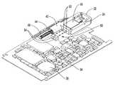
- FIG. 1is a perspective view of a retractable platform with a wireless interface in accordance with a preferred embodiment of the present invention, illustrating the retractable platform in connection with an exemplary expansion card that is insertable into a slot in a portable computer;
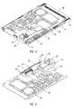
- FIG. 2is a perspective view of the retractable platform and expansion card illustrated in FIG. 1, illustrating the retractable platform in a retracted position and the top cover of the expansion card removed;
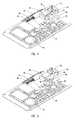
- FIG. 3is a perspective view of another preferred embodiment of the retractable platform, illustrating the retractable platform in an extended position and an optical coupling of the platform and an expansion card;
- FIG. 4is a perspective view of still another preferred embodiment of the retractable platform, illustrating the retractable platform in an extended position and an optical coupling of the platform and an expansion card;
- FIG. 5is a perspective view of yet another preferred embodiment of the retractable platform, illustrating the retractable platform in an extended position and an optical coupling of the platform and an extension card;
- FIG. 6is a perspective view of a further preferred embodiment of the retractable platform, illustrating an inductive coupling of the platform and an expansion card;
- FIG. 7is a perspective view of another preferred embodiment of the retractable platform, illustrating the retractable platform in a retracted position and a capacitive coupling of the platform and an expansion card;
- FIG. 8is an enlarged perspective view of the retractable platform shown in FIG. 7 .
- the present inventioninvolves a retractable platform that is coupled to an electronic device by a wireless or non-mechanical interface.
- the retractable platformis preferably connected to an expansion or communication card that allows a computer to be connected to a network or communication system.
- the principles of the present inventionare not limited to expansion cards or connectors that facilitate communication with networks or communication systems. It will be understood that, in light of the present disclosure, the retractable platform disclosed herein can be successfully used in connection with other types of electronic devices. Additionally, while the retractable platform is primarily discussed in connection with Personal Computer Memory Card International Association (PCMCIA) compliant communication cards, one skilled in the art will appreciate that the retractable platform can be used with any suitable type of communication card.
- PCMCIAPersonal Computer Memory Card International Association
- a portable computer 10includes an expansion slot 12 that is configured to receive an expansion or communication card 14 .
- the expansion card 14includes a first end 16 that is configured to be inserted into the slot 12 and a second end 18 that is generally disposed flush with an outer surface 20 of the computer 10 when the card is inserted into the slot.
- the computer 10can be any suitable type of general or special purpose computer, such as a desktop, portable, notebook, palm, personal data assistant (PDA), and the like.
- the communication card 14is configured to allow communication with systems or networks, such as telephone networks, local area networks (LANs), wide area networks (WANs), wireless networks and the like.
- the communication card 14preferably complies with the PCMCIA standards for a PC Card, but the card can be any suitable type of card such as an Advanced Technology Attachment (ATA) card, Compact Flash card, SmartMedia card, Solid State Floppy Disk Card (SSFDC), etc.
- ATAAdvanced Technology Attachment
- SSFDCSolid State Floppy Disk Card
- the communication card 14may comply with any suitable standards or guidelines, the card may also have other acceptable designs or characteristics.
- the card 14may facilitate communication with a network or system, the card may be configured to permit communication with any desirable type of device or interface.
- a retractable platform 22is connected to the second end 18 of the card 14 .
- the retractable platform 22includes an opening 24 that is sized and configured to removably receive a connector plug 26 that is connected to one end of media cable 28 .
- the opening 24is preferably sized and shaped to preclude insertion of electrically incompatible connector plugs and to prevent inadvertent attachment of plugs that contain electrical signals that could damage the electronics within the card 14 . This feature also precludes insertion of inverted connector plugs 26 .
- the other end of media cable 28includes a plug 30 that is capable of being inserted into a jack 32 .
- the jack 32is typically connected to a communication network, such as a telephone network, LAN, WAN, private branch exchange (PBX) system, or any suitable type of computer or communication network.
- PBXprivate branch exchange
- the jack 32may be connected to a peripheral device, such as a scanner, SCSI hard drive array or the like.
- the retractable platform 22preferably has a configuration and arrangement similar to or the same as the inventions disclosed in U.S. patent application Ser. No. 09/357,017, which was filed on Jul. 19, 1999, and U.S. Pat. Nos. 5,727,972; 5,547,401; 5,338,210; and 5,183,404 which are assigned to the same assignee as the present application and hereby incorporated by reference in their entireties.
- the retractable platform 22may have other suitable configurations and arrangements.
- the retractable platform 22may include other types of connections such as multiple pin connectors, 15-pin connectors, RJ-type connectors, dongle type connectors, coaxial cable connectors, etc.
- the retractable platform 22does not require the use of a connector that allows communication with a communication network or system.
- the retractable platform 22can be used to provide a wireless interface between any suitable types of electronic devices, such as a cellular telephones, pagers, digital cameras, identification systems, etc.
- the retractable platform 22is connected to the communication card 14 and disposed within the communication card is a substrate or printed circuit board (PCB) 34 along with various electronic circuitry and components 36 .
- the circuitry and components 36are arranged according to the desired functions and capabilities of the communication card 14 .
- the communication card 14also includes a connector 38 disposed at the front end 16 that is configured to electrically connect the card to the computer 10 and a guide 40 that is used to guide the movement of the retractable platform 22 .
- the guide 40engages an arm 42 of the retractable platform 22 and it guides the movement of the retractable platform 22 between an extended position and a retracted position. As seen in FIG.
- a spring 44may be used to move the retractable platform 22 into the extended position and hold the platform in a retracted position.
- the retractable platform 22 and the communication card 14are coupled by a wireless or non-mechanical interface that allows communication between the platform and card.
- a wireless or non-mechanical interfacethat allows communication between the platform and card.
- a wireless or non-mechanical interfacesuch as an optical, inductive or capacitive coupling, provides communication between the retractable platform 22 and the communication card 14 .
- a light or optical interface 50provides communication between the retractable platform 22 and the printed circuit board 34 of the communication card 14 .
- the optical interface 50includes one or more sensors 52 mounted to the retractable platform 24 and one or more sensors 54 attached to a suitable portion of the communication card 14 such as the printed circuit board 34 .
- the sensors 52 and 54are configured to transmit and/or receive light, such as infrared light (IR), to allow communication between the retractable platform 22 and the communication card 14 . Transmission and reception of information, and data and signals via light is well known to those skilled in the art and will not be described in detail herein.
- the retractable platform 22may also include circuitry and/or components 60 disposed within or on any suitable portion of the platform.
- the circuitry 60could process or manipulate the incoming and/or outgoing communication signals. Additionally, the circuitry could protect the communication card 14 from damage such as improperly coupling the retractable platform 22 to a digital or PBX communication line.
- the retractable platform 22could include a fuse, such as a fuse that satisfies the International Electrochemical Commission (IEC) 2000 fuse requirements, to prevent damage to the expansion card 14 and/or computer 10 .
- IECInternational Electrochemical Commission
- the circuitry 60could also be used, for example, to comply with suitable safety agency protocols.
- the circuitry 60may be used to satisfy safety standards such as Underwriter Laboratories, Inc. (UL) 1950 relating to the safety of information technology equipment, Canadian Standards Associates (CSA) 22.2 for power supplies, European Committee for Standardization (CEN) EN 60950 for safety of information technology and various standards set forth by the International Electrochemical Commission (IEC).
- ULUnderwriter Laboratories, Inc.
- CSACanadian Standards Associates
- CENEuropean Committee for Standardization
- IECInternational Electrochemical Commission
- the circuitry 60could be designed to comply with all or a portion of these standards.
- FIG. 4illustrates another preferred embodiment of the retractable platform 22 with a wireless interface.
- the optical interface 50includes one or more sensors 70 (shown in phantom) mounted to the retractable platform 22 and corresponding sensors (not shown) located in an arm 72 .
- the arm 72includes a first end 74 that extends over a portion of the body of the retractable platform 22 and a second end 76 that is mounted to the printed circuit board 34 .
- the sensors in the arm 72are preferably aligned with the sensors 70 on the retractable platform 22 when the platform is in the extended position, as shown in FIG. 4 .
- the sensors in the arm 72 and sensors 70 on the retractable platform 22are not aligned when the platform is in the retracted position.
- optical interface 50only occurs when the retractable platform is in the extended position and not when the retractable platform is in the retracted position. This prevents inadvertent or unintended communication when the retractable platform 22 is in the retracted position.
- optical interface 50could have other various suitable configurations and arrangements.
- FIG. 5illustrates another preferred embodiment of the retractable platform 22 including an optical interface 50 with one or more sensors 80 attached to a side 82 of the retractable platform.
- One or more corresponding sensors 84(shown in phantom) are mounted in housings 86 that are attached to the printed circuit board 34 .
- the housings 86are preferably located such that the sensors 84 are aligned with the sensors 80 to facilitate communication when the retractable platform 22 is in the extended position, but not when the retractable platform is in the retracted position.
- thisallows communication via the optical interface 50 only when the platform 22 is extended and not when it is retracted.
- thissaves power and allows for the more efficient use of resources within the communication card 10 .
- the power needed to transmit the signals between the sensors 80 and 84is minimized because the sensors are positioned proximate to each other.
- the optical interface 50requires a very small amount of valuable space on the printed circuit board 34 and a very small amount of space within the communication card 10 .
- the optical interface 50can be used with communication cards 10 and other types of electronic devices of various sizes and configurations.
- the close proximity of the sensors 80 and 84minimizes signal interference.
- another preferred embodiment of the retractable platform 22includes an inductive coupling 90 of the platform to the printed circuit board 34 of the communication card 14 .
- the inductive coupling 90includes an inductive strip 92 positioned along an upper surface 94 of the retractable platform 24 and a receiver arm 96 attached to the printed circuit board 34 .
- signalsare transmitted between the retractable platform 22 and the communication card 14 through the inductive strip 92 and receiver arm 96 of the inductive coupling 90 .
- signalscan be transmitted and received by the inductive coupling 90 and that allows the retractable platform 22 to communicate with the card 14 .
- the inductive coupling 90may have other desired configurations and arrangements, such as various types of conductive surfaces and receiving members.
- FIGS. 7 and 8illustrate another preferred embodiment of the retractable platform 22 with a capacitive coupling 100 that allows communication between the platform and the communication card 14 .
- the capacitive coupling 100includes a capacitive strip 102 located along an edge 104 of the guide 106 that guides the extension and retraction of the platform 22 .
- the capacitive coupling 100also includes a capacitive strip 108 located on the retractable platform 24 .
- the capacitive strip 108is disposed within the arm 42 of the retractable platform 22 , but the capacitive strip could be located in any suitable location.
- the conductive strips 102 and 108are positioned proximate to each other to allow signals and other information to be transmitted and received between the retractable platform 24 and the communication card 10 .
- the capacitive coupling 100allows bi-directional communication between the retractable platform 24 and the communication card 14 .
- the conductive coupling 100may have other suitable arrangements and characteristics depending, for example, upon the type of communication card 14 or electrical device.
- the capacitive coupling 100creates a non-mechanical interface between the retractable platform 22 and the communication card 14 .
- wireless interfacessuch as a conductive coupling or field effects, may also be used to allow communication between the retractable platform and an electronic device such as a communication card.
Landscapes
- Engineering & Computer Science (AREA)
- Theoretical Computer Science (AREA)
- Microelectronics & Electronic Packaging (AREA)
- Computer Hardware Design (AREA)
- Human Computer Interaction (AREA)
- Physics & Mathematics (AREA)
- General Engineering & Computer Science (AREA)
- General Physics & Mathematics (AREA)
- Telephone Set Structure (AREA)
Abstract
Description
Claims (26)
Priority Applications (1)
| Application Number | Priority Date | Filing Date | Title |
|---|---|---|---|
| US09/703,203US6542358B1 (en) | 2000-10-31 | 2000-10-31 | Retractable platform with wireless electrical interface |
Applications Claiming Priority (1)
| Application Number | Priority Date | Filing Date | Title |
|---|---|---|---|
| US09/703,203US6542358B1 (en) | 2000-10-31 | 2000-10-31 | Retractable platform with wireless electrical interface |
Publications (1)
| Publication Number | Publication Date |
|---|---|
| US6542358B1true US6542358B1 (en) | 2003-04-01 |
Family
ID=24824444
Family Applications (1)
| Application Number | Title | Priority Date | Filing Date |
|---|---|---|---|
| US09/703,203Expired - Fee RelatedUS6542358B1 (en) | 2000-10-31 | 2000-10-31 | Retractable platform with wireless electrical interface |
Country Status (1)
| Country | Link |
|---|---|
| US (1) | US6542358B1 (en) |
Cited By (30)
| Publication number | Priority date | Publication date | Assignee | Title |
|---|---|---|---|---|
| US20040090751A1 (en)* | 2002-11-08 | 2004-05-13 | Choi Dae Seon | Portable USB storage device |
| US20040266479A1 (en)* | 2003-06-24 | 2004-12-30 | Seung-Soo Oak | Network interface device |
| US6914189B1 (en)* | 2004-02-27 | 2005-07-05 | Intel Corporation | Electronic card with edge connector to minimize wear |
| US20050204086A1 (en)* | 2004-02-27 | 2005-09-15 | Imation Corp. | Memory card host connector with retractable shieldless tab |
| USD521953S1 (en)* | 2004-03-08 | 2006-05-30 | Mitsumi Electric Co., Ltd. | Transmitting unit |
| USD524763S1 (en)* | 2004-03-08 | 2006-07-11 | Mitsumi Electric Co., Ltd. | Transmitting/receiving unit |
| US20070254509A1 (en)* | 2006-04-28 | 2007-11-01 | Hon Hai Precision Industry Co., Ltd. | Electronic connecting device |
| US7315946B1 (en) | 2003-04-14 | 2008-01-01 | Aol Llc | Out-of-band tokens for rights access |
| US7373658B1 (en) | 2002-10-25 | 2008-05-13 | Aol Llc | Electronic loose-leaf remote control for enabling access to content from a media player |
| US20080244141A1 (en)* | 2007-03-30 | 2008-10-02 | Intel Corporation | High bandwidth cable extensions |
| US7647277B1 (en) | 2002-10-25 | 2010-01-12 | Time Warner Inc. | Regulating access to content using a multitiered rule base |
| USD637192S1 (en)* | 2010-10-18 | 2011-05-03 | Apple Inc. | Electronic device |
| USD637193S1 (en)* | 2010-11-19 | 2011-05-03 | Apple Inc. | Electronic device |
| US20120021638A1 (en)* | 2009-05-19 | 2012-01-26 | Edward Douglas Knapton | Modular network connector |
| US20140011379A1 (en)* | 2012-07-03 | 2014-01-09 | Alltop Electronics (Suzhou) Ltd. | Low profile electrical connector with reinforced pivotal cover |
| USD709894S1 (en)* | 2012-09-22 | 2014-07-29 | Apple Inc. | Electronic device |
| US9257802B2 (en) | 2012-07-03 | 2016-02-09 | Alltop Electronics (Suzhou) Ltd. | Slidable low profile electrical connector |
| USD767572S1 (en) | 2015-03-08 | 2016-09-27 | Apple Inc. | Component of an electronic device |
| USD768566S1 (en) | 2012-10-20 | 2016-10-11 | Apple Inc. | Battery |
| USD769833S1 (en)* | 2014-08-29 | 2016-10-25 | Apple Inc. | Component for electronic device |
| USD794034S1 (en)* | 2009-01-07 | 2017-08-08 | Samsung Electronics Co., Ltd. | Memory device |
| USD794642S1 (en)* | 2009-01-07 | 2017-08-15 | Samsung Electronics Co., Ltd. | Memory device |
| USD794643S1 (en)* | 2009-01-07 | 2017-08-15 | Samsung Electronics Co., Ltd. | Memory device |
| USD794641S1 (en)* | 2009-01-07 | 2017-08-15 | Samsung Electronics Co., Ltd. | Memory device |
| USD794644S1 (en)* | 2009-01-07 | 2017-08-15 | Samsung Electronics Co., Ltd. | Memory device |
| USD795262S1 (en)* | 2009-01-07 | 2017-08-22 | Samsung Electronics Co., Ltd. | Memory device |
| USD795261S1 (en)* | 2009-01-07 | 2017-08-22 | Samsung Electronics Co., Ltd. | Memory device |
| USD805027S1 (en) | 2015-03-06 | 2017-12-12 | Apple Inc. | Battery |
| USD843933S1 (en) | 2016-10-26 | 2019-03-26 | Apple Inc. | Battery |
| USD901484S1 (en) | 2012-10-20 | 2020-11-10 | Apple Inc. | Electronic device |
Citations (42)
| Publication number | Priority date | Publication date | Assignee | Title |
|---|---|---|---|---|
| US2916720A (en) | 1957-08-14 | 1959-12-08 | Robert B Steans | Electrical connector |
| US4186988A (en) | 1978-09-20 | 1980-02-05 | Amp Incorporated | Electrical connector receptacles |
| US4241974A (en) | 1979-05-02 | 1980-12-30 | Western Electric Company, Inc. | Multi-outlet adapter for modular telephone cords |
| US4303296A (en) | 1978-05-03 | 1981-12-01 | Bunker Ramo Corporation | Modular interface connector |
| US4352492A (en) | 1976-08-23 | 1982-10-05 | Fairchild Camera & Instrument Corp. | Data storage apparatus |
| JPS5834370A (en) | 1981-08-25 | 1983-02-28 | Nippon Telegr & Teleph Corp <Ntt> | Multiple wave analyzer |
| US4407559A (en) | 1981-04-09 | 1983-10-04 | Communications Systems, Inc. | Connector device with flush mounting receptacle, cover plate and terminal board |
| US4428636A (en) | 1981-11-05 | 1984-01-31 | Amp Incorporated | Multi-contact connectors for closely spaced conductors |
| JPS61256850A (en) | 1985-05-08 | 1986-11-14 | Fujitsu Ltd | Preventing plug for radio wave of telephone set |
| US4710136A (en) | 1982-02-26 | 1987-12-01 | Nippon Electric Co., Ltd. | Mounting structure for electronic apparatus or the like |
| US4778410A (en) | 1986-09-22 | 1988-10-18 | Hosiden Electronics Co., Ltd. | Jack |
| EP0355413A2 (en) | 1988-08-16 | 1990-02-28 | Feller Ag | Socket for electrical installation |
| US4915648A (en) | 1988-03-04 | 1990-04-10 | Fuji Jukogyo Kabushiki Kaisha | Connector with a lock mechanism |
| US5035641A (en) | 1988-02-15 | 1991-07-30 | Itt Industries Limited | Terminating insulated conductors |
| US5051099A (en) | 1990-01-10 | 1991-09-24 | Amp Incorporated | High speed card edge connector |
| US5139439A (en) | 1991-07-16 | 1992-08-18 | Veridata Electronics Inc. | Portable computer with detachable cartridge type interface device |
| US5183404A (en) | 1992-04-08 | 1993-02-02 | Megahertz Corporation | Systems for connection of physical/electrical media connectors to computer communications cards |
| US5184282A (en) | 1989-02-27 | 1993-02-02 | Mips Co., Ltd. | IC card adapter |
| US5391094A (en) | 1992-11-20 | 1995-02-21 | Murata Mfg. Co., Ltd. | Card-type line interface device |
| US5411405A (en) | 1993-11-12 | 1995-05-02 | Angia Communications, Inc. | Miniature electrical communications connectors |
| US5481616A (en) | 1993-11-08 | 1996-01-02 | Sparkomatic Corporation | Plug-in sound accessory for portable computers |
| US5499923A (en) | 1994-11-09 | 1996-03-19 | At&T Corp. | Communication card with extendible, rotatable coupling |
| US5505633A (en) | 1994-05-13 | 1996-04-09 | Intel Corporation | Integral external connector interface for thin form factor computer cards |
| US5509811A (en) | 1994-01-12 | 1996-04-23 | Dell Usa, L.P. | Computer enclosure with embedded PCMCIA modem card |
| US5538442A (en) | 1993-10-04 | 1996-07-23 | Murata Mfg. Co., Ltd. | Communication card |
| US5547401A (en) | 1992-04-08 | 1996-08-20 | Megahertz Corporation | Media connector interface for use with a thin-architecture communications card |
| US5561727A (en) | 1994-02-15 | 1996-10-01 | Sumitomo Electric Industries, Ltd. | Card-shaped optical data link device |
| US5562504A (en) | 1995-01-04 | 1996-10-08 | Simple Technology Incorporated | Communications card with integral transmission media line adaptor |
| US5608607A (en) | 1995-04-24 | 1997-03-04 | Compaq Computer Corporation | PCMCIA card and associated support and circuitry augmenting apparatus and methods |
| US5634802A (en) | 1994-08-18 | 1997-06-03 | International Business Machines Corporation | Retractable expandable jack |
| US5660568A (en) | 1995-01-04 | 1997-08-26 | Simple Technology, Inc. | Communications card with integral transmission media line adaptor |
| US5667395A (en) | 1994-08-29 | 1997-09-16 | Murata Mfg. Co., Ltd. | Communication card and structure of jack for use in the same |
| US5667390A (en) | 1995-03-06 | 1997-09-16 | Hon Hai Precision Ind. Co., Ltd. | I/O card and its associated cable harness assembly |
| US5679013A (en) | 1994-11-14 | 1997-10-21 | International Business Machines Corporation | Electrical connector and an electronic apparatus using the electrical connector |
| US5773332A (en) | 1993-11-12 | 1998-06-30 | Xircom, Inc. | Adaptable communications connectors |
| US5797771A (en) | 1996-08-16 | 1998-08-25 | U.S. Robotics Mobile Communication Corp. | Cable connector |
| US5816832A (en) | 1992-04-08 | 1998-10-06 | 3Com Corporation | Media connector interface for use with a PCMCIA-architecture communications card |
| US5892975A (en)* | 1995-05-31 | 1999-04-06 | Intel Corporation | System for wake-up module on PC card detecting switches had actuated and causing image to display to appear that was displayed when turned off |
| US6131136A (en)* | 1997-12-12 | 2000-10-10 | Gateway 2000, Inc. | Dual mode modem for automatically selecting between wireless and wire-based communication modes |
| US6217351B1 (en)* | 1999-08-16 | 2001-04-17 | 3Com Corporation | Adaptor module configured to be attached to a communication card |
| US6295207B1 (en)* | 1999-10-12 | 2001-09-25 | 3Com Corporation | Retractable and removable extensions with edge plated PCB's in thin-profile electronic devices |
| US6375479B1 (en)* | 2000-08-31 | 2002-04-23 | 3Com Corporation | Retractable connector with an alignment mechanism for use with electronic devices |
- 2000
- 2000-10-31USUS09/703,203patent/US6542358B1/ennot_activeExpired - Fee Related
Patent Citations (47)
| Publication number | Priority date | Publication date | Assignee | Title |
|---|---|---|---|---|
| US2916720A (en) | 1957-08-14 | 1959-12-08 | Robert B Steans | Electrical connector |
| US4352492A (en) | 1976-08-23 | 1982-10-05 | Fairchild Camera & Instrument Corp. | Data storage apparatus |
| US4303296A (en) | 1978-05-03 | 1981-12-01 | Bunker Ramo Corporation | Modular interface connector |
| US4186988A (en) | 1978-09-20 | 1980-02-05 | Amp Incorporated | Electrical connector receptacles |
| US4241974A (en) | 1979-05-02 | 1980-12-30 | Western Electric Company, Inc. | Multi-outlet adapter for modular telephone cords |
| US4407559A (en) | 1981-04-09 | 1983-10-04 | Communications Systems, Inc. | Connector device with flush mounting receptacle, cover plate and terminal board |
| JPS5834370A (en) | 1981-08-25 | 1983-02-28 | Nippon Telegr & Teleph Corp <Ntt> | Multiple wave analyzer |
| US4428636A (en) | 1981-11-05 | 1984-01-31 | Amp Incorporated | Multi-contact connectors for closely spaced conductors |
| US4710136A (en) | 1982-02-26 | 1987-12-01 | Nippon Electric Co., Ltd. | Mounting structure for electronic apparatus or the like |
| JPS61256850A (en) | 1985-05-08 | 1986-11-14 | Fujitsu Ltd | Preventing plug for radio wave of telephone set |
| US4778410A (en) | 1986-09-22 | 1988-10-18 | Hosiden Electronics Co., Ltd. | Jack |
| US5035641A (en) | 1988-02-15 | 1991-07-30 | Itt Industries Limited | Terminating insulated conductors |
| US4915648A (en) | 1988-03-04 | 1990-04-10 | Fuji Jukogyo Kabushiki Kaisha | Connector with a lock mechanism |
| EP0355413A2 (en) | 1988-08-16 | 1990-02-28 | Feller Ag | Socket for electrical installation |
| US5184282A (en) | 1989-02-27 | 1993-02-02 | Mips Co., Ltd. | IC card adapter |
| US5051099A (en) | 1990-01-10 | 1991-09-24 | Amp Incorporated | High speed card edge connector |
| US5139439A (en) | 1991-07-16 | 1992-08-18 | Veridata Electronics Inc. | Portable computer with detachable cartridge type interface device |
| US5183404A (en) | 1992-04-08 | 1993-02-02 | Megahertz Corporation | Systems for connection of physical/electrical media connectors to computer communications cards |
| US5336099A (en) | 1992-04-08 | 1994-08-09 | Megahertz Corporation | Media connector interface for use with a PCMCIA-architecture communications card |
| US5338210A (en) | 1992-04-08 | 1994-08-16 | Megahertz Corporation | Media connector interface for use with a PCMCIA-architecture communications card |
| US5816832A (en) | 1992-04-08 | 1998-10-06 | 3Com Corporation | Media connector interface for use with a PCMCIA-architecture communications card |
| US5727972A (en) | 1992-04-08 | 1998-03-17 | Aldous; Stephen C. | Media connector interface for use with a thin-architecture communications card |
| US5547401A (en) | 1992-04-08 | 1996-08-20 | Megahertz Corporation | Media connector interface for use with a thin-architecture communications card |
| US5391094A (en) | 1992-11-20 | 1995-02-21 | Murata Mfg. Co., Ltd. | Card-type line interface device |
| US5538442A (en) | 1993-10-04 | 1996-07-23 | Murata Mfg. Co., Ltd. | Communication card |
| US5481616A (en) | 1993-11-08 | 1996-01-02 | Sparkomatic Corporation | Plug-in sound accessory for portable computers |
| WO1995013633A1 (en) | 1993-11-12 | 1995-05-18 | Angia Communications, Inc. | Adaptable communications connectors |
| US6164989A (en)* | 1993-11-12 | 2000-12-26 | Glad; Paul H. | Adaptable communications connectors |
| US5411405A (en) | 1993-11-12 | 1995-05-02 | Angia Communications, Inc. | Miniature electrical communications connectors |
| US5773332A (en) | 1993-11-12 | 1998-06-30 | Xircom, Inc. | Adaptable communications connectors |
| US5509811A (en) | 1994-01-12 | 1996-04-23 | Dell Usa, L.P. | Computer enclosure with embedded PCMCIA modem card |
| US5561727A (en) | 1994-02-15 | 1996-10-01 | Sumitomo Electric Industries, Ltd. | Card-shaped optical data link device |
| US5505633A (en) | 1994-05-13 | 1996-04-09 | Intel Corporation | Integral external connector interface for thin form factor computer cards |
| US5634802A (en) | 1994-08-18 | 1997-06-03 | International Business Machines Corporation | Retractable expandable jack |
| US5667395A (en) | 1994-08-29 | 1997-09-16 | Murata Mfg. Co., Ltd. | Communication card and structure of jack for use in the same |
| US5499923A (en) | 1994-11-09 | 1996-03-19 | At&T Corp. | Communication card with extendible, rotatable coupling |
| US5679013A (en) | 1994-11-14 | 1997-10-21 | International Business Machines Corporation | Electrical connector and an electronic apparatus using the electrical connector |
| US5660568A (en) | 1995-01-04 | 1997-08-26 | Simple Technology, Inc. | Communications card with integral transmission media line adaptor |
| US5562504A (en) | 1995-01-04 | 1996-10-08 | Simple Technology Incorporated | Communications card with integral transmission media line adaptor |
| US5667390A (en) | 1995-03-06 | 1997-09-16 | Hon Hai Precision Ind. Co., Ltd. | I/O card and its associated cable harness assembly |
| US5608607A (en) | 1995-04-24 | 1997-03-04 | Compaq Computer Corporation | PCMCIA card and associated support and circuitry augmenting apparatus and methods |
| US5892975A (en)* | 1995-05-31 | 1999-04-06 | Intel Corporation | System for wake-up module on PC card detecting switches had actuated and causing image to display to appear that was displayed when turned off |
| US5797771A (en) | 1996-08-16 | 1998-08-25 | U.S. Robotics Mobile Communication Corp. | Cable connector |
| US6131136A (en)* | 1997-12-12 | 2000-10-10 | Gateway 2000, Inc. | Dual mode modem for automatically selecting between wireless and wire-based communication modes |
| US6217351B1 (en)* | 1999-08-16 | 2001-04-17 | 3Com Corporation | Adaptor module configured to be attached to a communication card |
| US6295207B1 (en)* | 1999-10-12 | 2001-09-25 | 3Com Corporation | Retractable and removable extensions with edge plated PCB's in thin-profile electronic devices |
| US6375479B1 (en)* | 2000-08-31 | 2002-04-23 | 3Com Corporation | Retractable connector with an alignment mechanism for use with electronic devices |
Non-Patent Citations (1)
| Title |
|---|
| IBM Technical Disclosure Bulletin, "Electrical Connector For Flat Flexible Cable," vol. 25, No. 1, Jun. 1982. |
Cited By (52)
| Publication number | Priority date | Publication date | Assignee | Title |
|---|---|---|---|---|
| US9231950B2 (en) | 2002-10-25 | 2016-01-05 | Time Warner Inc. | Out-of-band tokens for rights access |
| US8011007B2 (en) | 2002-10-25 | 2011-08-30 | Time Warner Inc. | Out-of-band tokens for rights access |
| US8584253B2 (en) | 2002-10-25 | 2013-11-12 | Time Warner Inc. | Out-of-band tokens for rights access |
| US10586221B1 (en) | 2002-10-25 | 2020-03-10 | Time Warner Inc. | Regulating access to content using a multitiered rule base |
| US7647277B1 (en) | 2002-10-25 | 2010-01-12 | Time Warner Inc. | Regulating access to content using a multitiered rule base |
| US9892241B2 (en) | 2002-10-25 | 2018-02-13 | Time Warner Inc. | Out-of band tokens for rights access |
| US20080163351A1 (en)* | 2002-10-25 | 2008-07-03 | Aol Llc | Out-of-band tokens for rights access |
| US7373658B1 (en) | 2002-10-25 | 2008-05-13 | Aol Llc | Electronic loose-leaf remote control for enabling access to content from a media player |
| US20040090751A1 (en)* | 2002-11-08 | 2004-05-13 | Choi Dae Seon | Portable USB storage device |
| US7133296B2 (en)* | 2002-11-08 | 2006-11-07 | Electronics And Telecommunications Research Institute | Portable USB storage device |
| US7315946B1 (en) | 2003-04-14 | 2008-01-01 | Aol Llc | Out-of-band tokens for rights access |
| US8018922B2 (en)* | 2003-06-24 | 2011-09-13 | Samsung Electronics Co., Ltd. | Network interface device |
| US20040266479A1 (en)* | 2003-06-24 | 2004-12-30 | Seung-Soo Oak | Network interface device |
| US7151673B2 (en)* | 2004-02-27 | 2006-12-19 | Imation Corp. | Memory card host connector with retractable shieldless tab |
| US20050204086A1 (en)* | 2004-02-27 | 2005-09-15 | Imation Corp. | Memory card host connector with retractable shieldless tab |
| US6914189B1 (en)* | 2004-02-27 | 2005-07-05 | Intel Corporation | Electronic card with edge connector to minimize wear |
| USD524763S1 (en)* | 2004-03-08 | 2006-07-11 | Mitsumi Electric Co., Ltd. | Transmitting/receiving unit |
| USD521953S1 (en)* | 2004-03-08 | 2006-05-30 | Mitsumi Electric Co., Ltd. | Transmitting unit |
| US20070254509A1 (en)* | 2006-04-28 | 2007-11-01 | Hon Hai Precision Industry Co., Ltd. | Electronic connecting device |
| US7445479B2 (en)* | 2006-04-28 | 2008-11-04 | Hon Hai Precision Industry Co., Ltd, | Electronic connecting device |
| US20080244141A1 (en)* | 2007-03-30 | 2008-10-02 | Intel Corporation | High bandwidth cable extensions |
| USD795262S1 (en)* | 2009-01-07 | 2017-08-22 | Samsung Electronics Co., Ltd. | Memory device |
| USD794643S1 (en)* | 2009-01-07 | 2017-08-15 | Samsung Electronics Co., Ltd. | Memory device |
| USD795261S1 (en)* | 2009-01-07 | 2017-08-22 | Samsung Electronics Co., Ltd. | Memory device |
| USD794644S1 (en)* | 2009-01-07 | 2017-08-15 | Samsung Electronics Co., Ltd. | Memory device |
| USD794641S1 (en)* | 2009-01-07 | 2017-08-15 | Samsung Electronics Co., Ltd. | Memory device |
| USD794034S1 (en)* | 2009-01-07 | 2017-08-08 | Samsung Electronics Co., Ltd. | Memory device |
| USD794642S1 (en)* | 2009-01-07 | 2017-08-15 | Samsung Electronics Co., Ltd. | Memory device |
| US20120021638A1 (en)* | 2009-05-19 | 2012-01-26 | Edward Douglas Knapton | Modular network connector |
| USD637192S1 (en)* | 2010-10-18 | 2011-05-03 | Apple Inc. | Electronic device |
| USD768134S1 (en) | 2010-10-18 | 2016-10-04 | Apple Inc. | Electronic device |
| USD637193S1 (en)* | 2010-11-19 | 2011-05-03 | Apple Inc. | Electronic device |
| USD686215S1 (en) | 2010-11-19 | 2013-07-16 | Apple Inc. | Electronic device |
| USD652041S1 (en)* | 2010-11-19 | 2012-01-10 | Apple Inc. | Electronic device |
| US8888516B2 (en)* | 2012-07-03 | 2014-11-18 | Alltop Electronics (Suzhou) Ltd. | Low profile electrical connector with reinforced pivotal cover |
| US20140011379A1 (en)* | 2012-07-03 | 2014-01-09 | Alltop Electronics (Suzhou) Ltd. | Low profile electrical connector with reinforced pivotal cover |
| US9257802B2 (en) | 2012-07-03 | 2016-02-09 | Alltop Electronics (Suzhou) Ltd. | Slidable low profile electrical connector |
| USD709894S1 (en)* | 2012-09-22 | 2014-07-29 | Apple Inc. | Electronic device |
| USD768566S1 (en) | 2012-10-20 | 2016-10-11 | Apple Inc. | Battery |
| USD1051122S1 (en) | 2012-10-20 | 2024-11-12 | Apple Inc. | Electronic device |
| USD901484S1 (en) | 2012-10-20 | 2020-11-10 | Apple Inc. | Electronic device |
| USD795823S1 (en) | 2014-08-29 | 2017-08-29 | Apple Inc. | Component for electronic device |
| USD769833S1 (en)* | 2014-08-29 | 2016-10-25 | Apple Inc. | Component for electronic device |
| USD805027S1 (en) | 2015-03-06 | 2017-12-12 | Apple Inc. | Battery |
| USD852737S1 (en) | 2015-03-06 | 2019-07-02 | Apple Inc. | Battery |
| USD893496S1 (en) | 2015-03-08 | 2020-08-18 | Apple Inc. | Component of an electronic device |
| USD874464S1 (en) | 2015-03-08 | 2020-02-04 | Apple Inc. | Component of an electronic device |
| USD825570S1 (en) | 2015-03-08 | 2018-08-14 | Apple Inc. | Component of an electronic device |
| USD926764S1 (en) | 2015-03-08 | 2021-08-03 | Apple Inc. | Component of an electronic device |
| USD767572S1 (en) | 2015-03-08 | 2016-09-27 | Apple Inc. | Component of an electronic device |
| USD843933S1 (en) | 2016-10-26 | 2019-03-26 | Apple Inc. | Battery |
| USD967753S1 (en) | 2016-10-26 | 2022-10-25 | Apple Inc. | Battery |
Similar Documents
| Publication | Publication Date | Title |
|---|---|---|
| US6542358B1 (en) | Retractable platform with wireless electrical interface | |
| US6174205B1 (en) | Communication card extension and adapter port | |
| US6217351B1 (en) | Adaptor module configured to be attached to a communication card | |
| US7014486B1 (en) | Recoverable connector structure and cradle having the same | |
| US5505633A (en) | Integral external connector interface for thin form factor computer cards | |
| US5608606A (en) | Computer plug-in module and interconnection system for wireless applications | |
| US5509811A (en) | Computer enclosure with embedded PCMCIA modem card | |
| CN201233973Y (en) | Backward Compatible Connector System | |
| US6190182B1 (en) | Piggy back PC card | |
| US8326347B2 (en) | Wireless communication system integrated into a computer display | |
| US20020118135A1 (en) | Retractable antenna for electronic devices | |
| US5642259A (en) | Arrangement for connecting an expansion card to a connector socket in a personal computer | |
| US6375479B1 (en) | Retractable connector with an alignment mechanism for use with electronic devices | |
| US5989042A (en) | Electrical connector for use between shielded media connectors and computer communications cards | |
| US20020076954A1 (en) | Personal computer card having receptacle for mounting therein micro card | |
| US6295197B1 (en) | Wireless communication apparatus | |
| EP0710059A2 (en) | Folding data communication device | |
| US6488543B2 (en) | Modular jack for type III PCMCIA cards | |
| US6980159B2 (en) | Portable electrical device with planar antenna | |
| US5649224A (en) | Integrated circuit card having contacts along the side rails and method for transferring information using the contacts | |
| US20040257761A1 (en) | AC/DC adapter and notebook computer using the same | |
| US6033240A (en) | Retractable media jack operable with two discrete media connectors | |
| JP3810265B2 (en) | Computer system | |
| EP1125368B1 (en) | Battery case for pcmcia card modem with antenna | |
| US6524122B1 (en) | Retractable connector for use with electronic devices |
Legal Events
| Date | Code | Title | Description |
|---|---|---|---|
| AS | Assignment | Owner name:3COM CORPORATION, CALIFORNIA Free format text:ASSIGNMENT OF ASSIGNORS INTEREST;ASSIGNORS:KUNZ, RYAN;PRICE, TIM URRY;EVANS, JOHN;AND OTHERS;REEL/FRAME:011555/0013;SIGNING DATES FROM 20001026 TO 20010216 | |
| AS | Assignment | Owner name:3COM CORPORATION, CALIFORNIA Free format text:CORRECTIVE ASSIGNMENT TO CORRECT THE ASSIGNEE'S STATE OF INCORPORATION AS IT APPEARS IN THE BODY OF THE DOCUMENT PREVIOUSLY RECORDED ON REEL 011555, FRAME 0013;ASSIGNORS:KUNZ, RYAN;PRICE, TIM URRY;EVANS, JOHHN;AND OTHERS;REEL/FRAME:014302/0664;SIGNING DATES FROM 20001026 TO 20010216 | |
| FPAY | Fee payment | Year of fee payment:4 | |
| AS | Assignment | Owner name:HEWLETT-PACKARD COMPANY, CALIFORNIA Free format text:MERGER;ASSIGNOR:3COM CORPORATION;REEL/FRAME:024630/0820 Effective date:20100428 | |
| AS | Assignment | Owner name:HEWLETT-PACKARD COMPANY, CALIFORNIA Free format text:CORRECTIVE ASSIGNMENT TO CORRECT THE SEE ATTACHED;ASSIGNOR:3COM CORPORATION;REEL/FRAME:025039/0844 Effective date:20100428 | |
| FPAY | Fee payment | Year of fee payment:8 | |
| AS | Assignment | Owner name:HEWLETT-PACKARD DEVELOPMENT COMPANY, L.P., TEXAS Free format text:ASSIGNMENT OF ASSIGNORS INTEREST;ASSIGNOR:HEWLETT-PACKARD COMPANY;REEL/FRAME:027329/0044 Effective date:20030131 | |
| AS | Assignment | Owner name:HEWLETT-PACKARD DEVELOPMENT COMPANY, L.P., TEXAS Free format text:CORRECTIVE ASSIGNMENT PREVIUOSLY RECORDED ON REEL 027329 FRAME 0001 AND 0044;ASSIGNOR:HEWLETT-PACKARD COMPANY;REEL/FRAME:028911/0846 Effective date:20111010 | |
| REMI | Maintenance fee reminder mailed | ||
| LAPS | Lapse for failure to pay maintenance fees | ||
| STCH | Information on status: patent discontinuation | Free format text:PATENT EXPIRED DUE TO NONPAYMENT OF MAINTENANCE FEES UNDER 37 CFR 1.362 | |
| FP | Lapsed due to failure to pay maintenance fee | Effective date:20150401 |