US6542119B2 - GPS antenna array - Google Patents
GPS antenna arrayDownload PDFInfo
- Publication number
- US6542119B2 US6542119B2US09/863,956US86395601AUS6542119B2US 6542119 B2US6542119 B2US 6542119B2US 86395601 AUS86395601 AUS 86395601AUS 6542119 B2US6542119 B2US 6542119B2
- Authority
- US
- United States
- Prior art keywords
- gps
- satellite data
- antenna
- antennas
- satellite
- Prior art date
- Legal status (The legal status is an assumption and is not a legal conclusion. Google has not performed a legal analysis and makes no representation as to the accuracy of the status listed.)
- Expired - Fee Related
Links
- 238000000034methodMethods0.000claimsdescription30
- 230000005540biological transmissionEffects0.000abstractdescription12
- 238000005070samplingMethods0.000abstractdescription6
- 238000010586diagramMethods0.000description5
- 238000003491arrayMethods0.000description2
- 230000008901benefitEffects0.000description2
- 238000012986modificationMethods0.000description2
- 230000004048modificationEffects0.000description2
- 229920001690polydopaminePolymers0.000description2
- 230000001351cycling effectEffects0.000description1
- 230000001419dependent effectEffects0.000description1
- 230000007613environmental effectEffects0.000description1
Images


Classifications
- G—PHYSICS
- G01—MEASURING; TESTING
- G01S—RADIO DIRECTION-FINDING; RADIO NAVIGATION; DETERMINING DISTANCE OR VELOCITY BY USE OF RADIO WAVES; LOCATING OR PRESENCE-DETECTING BY USE OF THE REFLECTION OR RERADIATION OF RADIO WAVES; ANALOGOUS ARRANGEMENTS USING OTHER WAVES
- G01S19/00—Satellite radio beacon positioning systems; Determining position, velocity or attitude using signals transmitted by such systems
- G01S19/01—Satellite radio beacon positioning systems transmitting time-stamped messages, e.g. GPS [Global Positioning System], GLONASS [Global Orbiting Navigation Satellite System] or GALILEO
- G01S19/13—Receivers
- G01S19/35—Constructional details or hardware or software details of the signal processing chain
- G01S19/36—Constructional details or hardware or software details of the signal processing chain relating to the receiver frond end
Definitions
- the present inventiongenerally pertains to antennas and more particularly to the use of multiple antennas for detecting GPS signals.
- GPS signals that are broadcast from satellites in stationary orbitsare used by GPS receivers for generating location data to locate the receiver. More accurate location information can be generated as more satellites are detected.
- satellite signalsmay be difficult to detect.
- the GPS receivermay have a narrow satellite view and be able to only detect satellites in certain predetermined directions.
- high foliage areas and other environmental effectsmay limit the direction in which satellite information can be detected.
- telemetric devicesmay be used to track the location of a car. If a car is in an accident and turned over or sideways, a single GPS antenna may not be able to detect any satellite information because of the directional nature of the GPS antenna. The telemetric device would then be rendered useless.
- objectsmay be stacked or placed on top of a telemetric device, or other GPS receiver, which may block a single GPS antenna from receiving any satellite data.
- a GPS receivermay be attached to devices that are rotated, such as a cell phone or PDA, or caused to go into a dive, such as airplanes or other devices.
- the directional nature of the GPS antennaagain, may prevent a single GPS antenna from receiving satellite broadcasts that will allow the GPS device to generate location data. There are numerous scenarios in which this may occur.
- the present inventionovercomes the disadvantages and limitations of the prior art by providing a GPS antenna array that is capable of detecting GPS satellite transmissions in multiple directions.
- the present inventionmay be employed on a telemetric device in which GPS antennas are located on each side of a box holding the telemetric device.
- a relay switching arraycan be used to switch from one antenna to the next so that satellite information can be received from multiple antennas.
- the relaymay cycle through each of the antennas, acquire satellites, process GPS data, store tracing information for each acquired satellite and then proceed to the next antenna. After each of the antennas has been sampled, the positional information can be calculated and stored in the GPS device.
- the present inventionmay therefore comprise a method of detecting GPS satellite data from multiple directions comprising: providing a GPS antenna array having multiple antennas disposed in various orientations; providing a switch that is capable of connecting the multiple antennas to a GPS receiver; controlling the switch so that the GPS satellite data can be detected by the GPS receiver from the multiple antennas.
- the present inventionmay further comprise a method of connecting a multiple GPS antenna array to a GPS receiver so that GPS satellite data can be detected from multiple directions comprising: connecting the GPS receiver to a first antenna of the multiple GPS antenna array; determining if the GPS satellite data can be acquired by the first antenna; detecting the GPS satellite data that can be acquired; switching to a next antenna whenever the GPS satellite data cannot be acquired; storing the GPS satellite data.
- the presentmay further comprise a device for detecting GPS satellite data from multiple directions comprising: a GPS antenna array having multiple GPS antennas that are oriented in multiple directions; a switch that is connected to the GPS antenna array; a GPS receiver coupled to the switch that controls the switch such that the GPS receiver is connected to the multiple GPS antennas to receive the GPS satellite data from multiple directions and changes connections to the multiple GPS antennas whenever the GPS satellite data is not acquired.
- a device for detecting GPS satellite data from multiple directionscomprising: a GPS antenna array having multiple GPS antennas that are oriented in multiple directions; a switch that is connected to the GPS antenna array; a GPS receiver coupled to the switch that controls the switch such that the GPS receiver is connected to the multiple GPS antennas to receive the GPS satellite data from multiple directions and changes connections to the multiple GPS antennas whenever the GPS satellite data is not acquired.
- the advantages of the present inventionare that satellite data can be detected from multiple directions which allows the GPS receiver to detect satellite data in multiple orientations.
- the GPS antenna arraycan be disposed on any desired GPS receiver, including telemetric devices, cell phones, PDAs, etc.
- the directional nature of the GPS antennacan then be maintained to increase reception while not sacrificing the ability to detect satellite data from various directions. For example, if a telemetric device is mounted in an automobile and if that automobile is in a wreck and turned on its side or turned over, the telemetric device employing the present invention will still have one or more antennas that are oriented towards the sky that will enable the telemetric device to receive satellite transmissions.
- FIG. 1is a schematic diagram of one implementation of the present invention on a telemetric device.
- FIG. 2is a schematic diagram illustrating the manner in which a GPS antenna array may be connected to a GPS receiver.
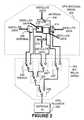
- FIG. 3is a schematic illustration of the use of the present invention in an urban environment.
- FIG. 4is a flow chart illustrating the functions of the GPS controller.
- FIG. 1is a schematic diagram of one implementation of the present invention on a telemetric device 100 .
- Telemetric devicesare used to track property such as automobiles and other motor vehicles. Telemetric devices normally include a GPS receiver together with a cell phone that transmits the location information to a central tracking station.
- a telemetric devicecan be used as a handheld device such as a cell phone or may be incorporated as part of a personal data assistant (PDA). Each of these devices may be adjusted or used in various orientations.
- the telemetric device 100may therefore include various GPS antennas such as GPS antenna 102 , 104 , 106 , 108 , 110 , 112 that are disposed on various surfaces of the telemetric device 100 .
- the GPS antennasIn order for the GPS antennas to have at least a moderate degree of gain, they must be somewhat directional in nature. The more directional the GPS antenna is made, the higher the gain of the antenna. Hence, it is desirable to be able to use an array of GPS antennas that are oriented in various directions such as shown in FIG. 1 that are more directional in nature since these antennas will have a higher degree of gain. This allows the telemetric device 100 to detect GPS satellite transmissions in multiple orientations. For example, if a handheld cell phone is equipped with a GPS receiver, the handheld telephone can be oriented in multiple directions and still be able to receive GPS satellite transmissions with a high degree of gain.
- Antenna arrayshave been used previously for detecting signals or transmitting signals from multiple directions.
- each of the following patentsdiscloses multiple antenna arrays: U.S. Pat. Nos. 5,258,766, 2,422,026, 5,047,715, 5,552,798, 5,818,393, 6,069,564, 6,075,486, 6,094,173, and Offenlegungsschrift U.S. Pat. No. 1,927,146, all of which are specifically incorporated herein by reference for all that they disclose and teach. None of these patents, however, disclose the use of an antenna array with a GPS receiver for receiving GPS satellite transmissions from multiple directions. Further, there is no disclosure of the use of such an array with a telemetric device. Also, these devices do not disclose an integrated switching array and a process for switching between the antennas that allows the GPS receiver to acquire one or more satellites prior to switching to the next antenna and array.
- FIG. 2is a schematic diagram of one implementation of the present invention.
- a GPS receiver 200is connected to a RF relay array 202 via the antenna input to the GPS receiver 200 .
- the RF switching relay 202is in turn connected to a GPS antenna array 204 .
- the GPS antenna arraymay include multiple antennas such as antennas 206 , 208 , 210 , 212 , 214 and 216 . These antennas are disposed in six different directions to receive satellite transmissions from six different directions, as illustrated in FIG. 2 . Each of the six antennas is then connected to the RF switching relay array 202 .
- the RF switching relay array 202includes switches 218 , 220 , 222 , 224 and 226 .
- Each of the switches 218 - 226is operated under the control of a controller in the GPS receiver 200 .
- Embedded software in the controller of the GPS receiver 200is programmed to activate the switches 218 - 226 in accordance with the process described in FIG. 4 .
- the embedded software in the GPS receiver 200controls the cycling of the sampling of the GPS antenna array in accordance with the satellite data that is received by each one of the antennas 202 - 216 .
- the GPS receiver 200detects and stores the tracing information of each of the acquired satellites from each of the antennas 202 - 216 .
- the tracing informationis then used in the next cycle through the antenna array so that the GPS receiver 200 can predict which satellites it can expect to see. By storing and using tracing information, in this fashion, from a previous scan through the antenna array, acquisition time during the next cycle is shortened.
- the system illustrated in FIG. 2has a sampling rate that is dependent upon the number of satellites acquired by each of the antennas 202 - 216 . For example, if antenna 206 acquires three satellites with valid data, the embedded software of the GPS receiver will pause sufficiently to acquire the satellite data prior to switching to the next antenna. If the next antenna does not acquire any satellite data, the process will switch to the next antenna. This is described more fully with regard to FIG. 4 .
- the antennas 202 - 216are oriented in six different directions to receive satellite data. Of course, any number of antennas can be used that are oriented in any desired direction to obtain satellite data from multiple orientations.
- FIG. 3is a schematic illustration of the use of the present invention in an urban environment.
- buildings 300 , 302may exist in an urban environment.
- a GPS receiver 324can be used in accordance with the present invention that employs multiple antennas 312 , 314 , 316 , 318 , 320 and 322 that may be oriented, as shown in FIG. 3, in six different directions.
- the GPS receiver 324may comprise a handheld PDA, a cell phone, a telemetric device mounted on a motor vehicle or on a simple GPS receiver such as a handheld GPS receiver.
- satellite data 304 and 306is detected by antennas 316 and 312 , respectively. The other antennas do not detect any satellite data.
- antenna 314does not detect any satellite data 308 in the direction of antenna 314 .
- antenna 318does not detect any satellite data 310 in the direction of antenna 318 .
- the urban environment created by the buildings 300 , 302narrows the viewing angle for the satellite data so that only satellite data 304 , 306 is transmitted between the buildings 300 , 302 .
- the GPS receiver 324can be oriented in various multiple directions and still be able to receive the narrow angle of satellite data in the urban environment.
- FIG. 4is a flow diagram that illustrates the functions performed by embedded software in a GPS controller.
- the GPS controllermay comprise a microprocessor that is included within the GPS receiver device.
- the embedded softwarecan be used to control the functions of the microprocessor of the GPS receiver to perform the functions illustrated in FIG. 4 .
- any desired type of controller or logic devicecan be employed including a state machine, etc.
- the radio frequency relay arrayconnects the GPS receiver antenna input, as illustrated in FIG. 2, to the first antenna, such as antenna 208 illustrated in FIG. 2 .
- the RF switch relay arraycan comprise a separate chip, that is mounted on a GPS receiver board, that is connected to the antenna input of the GPS receiver.
- Control circuits for the RF relay arraycan be controlled by output drivers of the microprocessor circuit.
- the GPS receiverdetermines whether a first satellite has been acquired. A certain predetermined period may be provided to acquire the first satellite. Additionally, stored tracing information as to the satellite may be used by the GPS receiver if available. Tracing information may be stored and available from a previous cycle through the antenna array, for example. If the period for detecting the first satellite has timed out, the process proceeds to step 418 . If the first satellite is acquired, the process proceeds to step 408 where the GPS data received from the first satellite is processed and stored. At step 410 , tracing information for the first satellite is stored. The process then proceeds to step 412 where the GPS receiver determines if a next satellite can be acquired.
- Another predetermined periodis provided for acquiring the next satellite.
- Stored tracing informationmay be used for acquiring the satellite if it is available, in the same manner as described above. If the satellite is not acquired, the process proceeds to step 418 . If the next satellite is acquired, the process proceeds to step 414 where the GPS data from the next satellite is processed and stored. Tracing information for the next satellite is stored at step 416 . The process then returns to step 412 and the process is repeated.
- the GPS receiverdetermines if a first satellite is acquired using the next antenna at step 420 . Again, a predetermined timeout period may be used as described above. Stored tracing information can also be used to acquire the first satellite if it is available. If the first satellite is not acquired within the timeout period, the process proceeds to step 432 . If the first satellite is acquired by the next antenna, the process proceeds to step 422 where the GPS data is processed from the first satellite and stored. At step 424 , tracing information for the first satellite is stored. The process then proceeds to step 426 where the GPS receiver determines if a next satellite can be acquired during a predetermined period. Again, stored tracing information can be used if available.
- step 432If the satellite cannot be acquired within the predetermined timeout period, the process proceeds to step 432 . If the next satellite is acquired, the process proceeds to step 428 where the GPS data is processed from the next satellite and stored. The process then proceeds to step 430 to store the tracing information from the next satellite. The process returns to step 426 to see if the next satellite can be acquired.
- the GPS receiverdetermines if the antenna is the sixth antenna. If it is not, the process returns to step 418 to connect the RF relay array to the next antenna. If it is the sixth antenna, the process may then proceed to step 434 where the positional information is calculated from the stored GPS data. The positional information is then stored by the GPS receiver and used as desired.
- the process illustrated in FIG. 4can be varied and does not necessarily need to be processed in the order illustrated above.
- the functions described by the GPS controller, as described with regard to FIG. 4,allow the sampling period to be adjusted for each of the individual antennas depending upon the acquisition of GPS satellite transmissions and the processing of that data. Sampling may proceed at a much higher rate if fewer satellites are acquired. In any event, the entire cycle time for six antennas should not exceed approximately one second.
- the present inventiontherefore provides a unique system for using a multiple antenna array that samples GPS antennas at varying rates depending upon the acquisition of satellite transmissions.
- the system of the present inventionallows GPS data to be detected when the GPS receiver is oriented in various directions and allows the use of more directional type antennas with higher gain for better reception. Cycle time for sampling each of the antennas can vary in accordance with acquisition of satellite transmissions.
- the antenna arraycan be designed in any desired orientation to receive GPS satellite transmissions from multiple orientations. This can be useful in cell phone devices having GPS receivers, PDAs having GPS receivers and other telemetric devices that may acquire multiple orientations.
Landscapes
- Engineering & Computer Science (AREA)
- Radar, Positioning & Navigation (AREA)
- Remote Sensing (AREA)
- Signal Processing (AREA)
- Computer Networks & Wireless Communication (AREA)
- Physics & Mathematics (AREA)
- General Physics & Mathematics (AREA)
- Position Fixing By Use Of Radio Waves (AREA)
- Variable-Direction Aerials And Aerial Arrays (AREA)
Abstract
Description
Claims (10)
Priority Applications (1)
| Application Number | Priority Date | Filing Date | Title |
|---|---|---|---|
| US09/863,956US6542119B2 (en) | 2000-05-23 | 2001-05-23 | GPS antenna array |
Applications Claiming Priority (2)
| Application Number | Priority Date | Filing Date | Title |
|---|---|---|---|
| US20634300P | 2000-05-23 | 2000-05-23 | |
| US09/863,956US6542119B2 (en) | 2000-05-23 | 2001-05-23 | GPS antenna array |
Publications (2)
| Publication Number | Publication Date |
|---|---|
| US20020044085A1 US20020044085A1 (en) | 2002-04-18 |
| US6542119B2true US6542119B2 (en) | 2003-04-01 |
Family
ID=26901260
Family Applications (1)
| Application Number | Title | Priority Date | Filing Date |
|---|---|---|---|
| US09/863,956Expired - Fee RelatedUS6542119B2 (en) | 2000-05-23 | 2001-05-23 | GPS antenna array |
Country Status (1)
| Country | Link |
|---|---|
| US (1) | US6542119B2 (en) |
Cited By (12)
| Publication number | Priority date | Publication date | Assignee | Title |
|---|---|---|---|---|
| US20030013470A1 (en)* | 2001-07-10 | 2003-01-16 | Tim Forrester | System and method for providing GPS-enabled wireless communications |
| US20030151552A1 (en)* | 2002-02-11 | 2003-08-14 | Johannes Ilq | Circuit for the selective activation of a plurality of antennas from a common end stage |
| US20080181057A1 (en)* | 2006-12-26 | 2008-07-31 | Aram Systems, Ltd. | PseudoRover GPS receiver |
| US20110279310A1 (en)* | 2007-09-13 | 2011-11-17 | Hideto Shibohta | Radio wave receiving apparatus and position calculating method |
| US20150263434A1 (en) | 2013-03-15 | 2015-09-17 | SeeScan, Inc. | Dual antenna systems with variable polarization |
| US9716314B2 (en) | 2015-05-11 | 2017-07-25 | Taoglas Group Holdings | Steering systems and methods |
| US20190288390A1 (en)* | 2018-02-21 | 2019-09-19 | Antenna Research Associates | Passive electronically scanned array (pesa) |
| US10608348B2 (en) | 2012-03-31 | 2020-03-31 | SeeScan, Inc. | Dual antenna systems with variable polarization |
| US11050151B2 (en) | 2019-06-04 | 2021-06-29 | City University Of Hong Kong | Multi-band antenna |
| US11063357B2 (en) | 2019-06-04 | 2021-07-13 | City University Of Hong Kong | Dual-band antenna for global positioning system |
| US12088013B2 (en) | 2021-03-30 | 2024-09-10 | Skyworks Solutions, Inc. | Frequency range two antenna array with switches for joining antennas for frequency range one communications |
| US12176618B2 (en) | 2022-12-09 | 2024-12-24 | L3Harris Global Communications, Inc. | Systems and methods for providing an antenna |
Families Citing this family (15)
| Publication number | Priority date | Publication date | Assignee | Title |
|---|---|---|---|---|
| JP2001356159A (en)* | 2000-06-15 | 2001-12-26 | Seiko Epson Corp | GPS receiving system |
| GB0224277D0 (en)* | 2002-10-18 | 2002-11-27 | Koninkl Philips Electronics Nv | Electroluminescent display devices |
| GB0225204D0 (en)* | 2002-10-30 | 2002-12-11 | Koninkl Philips Electronics Nv | GPS receiver |
| US20060205368A1 (en)* | 2005-03-14 | 2006-09-14 | Motorola, Inc. | Selecting an optimal antenna according to an operating state of a device |
| EP1717594A1 (en)* | 2005-04-21 | 2006-11-02 | Infineon Technologies AG | A receiver with increased sensitivity |
| TWI275203B (en)* | 2005-12-30 | 2007-03-01 | Inventec Appliances Corp | Antenna system of GPS receiver and switching method of antenna |
| TWI293689B (en)* | 2006-03-24 | 2008-02-21 | Asustek Comp Inc | Handheld gps device |
| US7847730B2 (en)* | 2006-09-27 | 2010-12-07 | Bae Systems Information And Electronic Systems Integration, Inc. | Software defined navigation signal generator |
| BRPI0700953A (en)* | 2007-03-14 | 2008-10-28 | De Abreu Espedito Alves | gps antenna diversity module with receiver protection and integrated alarm signaling |
| EP2282412B1 (en)* | 2009-07-22 | 2012-12-19 | Nxp B.V. | Adaptation of a directional characteristic of a radio signal based on the spatial orientation of a radio transmitter |
| US20120092215A1 (en)* | 2010-10-13 | 2012-04-19 | Yat Wai Edwin Kwong | Systems and methods for obtaining a position of a cargo container |
| FR2988483B1 (en)* | 2012-03-22 | 2014-03-07 | Thales Sa | DEVICE FOR RECEIVING MULTI-ANTENNA RADIO NAVIGATION SIGNALS |
| WO2013183033A2 (en) | 2012-06-08 | 2013-12-12 | Koninklijke Philips N.V. | A method of determining the position of a device and a device that implements the method |
| CN107745814B (en)* | 2017-11-15 | 2023-12-22 | 航宇救生装备有限公司 | Active anti-overturning control mechanism for landing of air drop system |
| US11988755B1 (en)* | 2020-04-20 | 2024-05-21 | SeeScan, Inc. | Utility locating devices employing multiple spaced apart GNSS antennas |
Citations (14)
| Publication number | Priority date | Publication date | Assignee | Title |
|---|---|---|---|---|
| US2422026A (en) | 1943-07-28 | 1947-06-10 | Rca Corp | Radio direction finding |
| DE1927146A1 (en) | 1967-09-22 | 1970-12-03 | Messerschmitt Boelkow Blohm | Omnidirectional antenna |
| US4845507A (en)* | 1987-08-07 | 1989-07-04 | Raytheon Company | Modular multibeam radio frequency array antenna system |
| US5047715A (en) | 1987-12-22 | 1991-09-10 | Morgenstern Juergen | Electromagnetic device for position measurement having multiple coils with equal area of turn cross-section |
| US5258766A (en) | 1987-12-10 | 1993-11-02 | Uniscan Ltd. | Antenna structure for providing a uniform field |
| US5334987A (en)* | 1993-04-01 | 1994-08-02 | Spectra-Physics Laserplane, Inc. | Agricultural aircraft control system using the global positioning system |
| US5410321A (en)* | 1993-09-29 | 1995-04-25 | Texas Instruments Incorporated | Directed reception pattern antenna |
| US5552798A (en) | 1994-08-23 | 1996-09-03 | Globalstar L.P. | Antenna for multipath satellite communication links |
| US5657024A (en)* | 1994-10-13 | 1997-08-12 | Honda Giken Kogyo Kabushiki Kaisha | Radar module and radar system |
| US5818393A (en) | 1991-12-10 | 1998-10-06 | Raytheon Ti Systems, Inc. | Wide field-of-view fixed body conformal antenna direction finding array |
| US6069564A (en) | 1998-09-08 | 2000-05-30 | Hatano; Richard | Multi-directional RFID antenna |
| US6075486A (en) | 1998-07-03 | 2000-06-13 | Mitsubishi Denki Kabushiki Kaisha | Antenna device |
| US6094173A (en) | 1997-04-18 | 2000-07-25 | Motorola, Inc. | Method and apparatus for detecting an RFID tag signal |
| US6121925A (en)* | 1999-09-01 | 2000-09-19 | The United States Of America As Represented By The Secretary Of The Army | Data-link and antenna selection assembly |
- 2001
- 2001-05-23USUS09/863,956patent/US6542119B2/ennot_activeExpired - Fee Related
Patent Citations (14)
| Publication number | Priority date | Publication date | Assignee | Title |
|---|---|---|---|---|
| US2422026A (en) | 1943-07-28 | 1947-06-10 | Rca Corp | Radio direction finding |
| DE1927146A1 (en) | 1967-09-22 | 1970-12-03 | Messerschmitt Boelkow Blohm | Omnidirectional antenna |
| US4845507A (en)* | 1987-08-07 | 1989-07-04 | Raytheon Company | Modular multibeam radio frequency array antenna system |
| US5258766A (en) | 1987-12-10 | 1993-11-02 | Uniscan Ltd. | Antenna structure for providing a uniform field |
| US5047715A (en) | 1987-12-22 | 1991-09-10 | Morgenstern Juergen | Electromagnetic device for position measurement having multiple coils with equal area of turn cross-section |
| US5818393A (en) | 1991-12-10 | 1998-10-06 | Raytheon Ti Systems, Inc. | Wide field-of-view fixed body conformal antenna direction finding array |
| US5334987A (en)* | 1993-04-01 | 1994-08-02 | Spectra-Physics Laserplane, Inc. | Agricultural aircraft control system using the global positioning system |
| US5410321A (en)* | 1993-09-29 | 1995-04-25 | Texas Instruments Incorporated | Directed reception pattern antenna |
| US5552798A (en) | 1994-08-23 | 1996-09-03 | Globalstar L.P. | Antenna for multipath satellite communication links |
| US5657024A (en)* | 1994-10-13 | 1997-08-12 | Honda Giken Kogyo Kabushiki Kaisha | Radar module and radar system |
| US6094173A (en) | 1997-04-18 | 2000-07-25 | Motorola, Inc. | Method and apparatus for detecting an RFID tag signal |
| US6075486A (en) | 1998-07-03 | 2000-06-13 | Mitsubishi Denki Kabushiki Kaisha | Antenna device |
| US6069564A (en) | 1998-09-08 | 2000-05-30 | Hatano; Richard | Multi-directional RFID antenna |
| US6121925A (en)* | 1999-09-01 | 2000-09-19 | The United States Of America As Represented By The Secretary Of The Army | Data-link and antenna selection assembly |
Cited By (17)
| Publication number | Priority date | Publication date | Assignee | Title |
|---|---|---|---|---|
| US7035654B2 (en)* | 2001-07-10 | 2006-04-25 | Kyocera Wireless Corp. | System and method for providing GPS-enabled wireless communications |
| US20030013470A1 (en)* | 2001-07-10 | 2003-01-16 | Tim Forrester | System and method for providing GPS-enabled wireless communications |
| US20030151552A1 (en)* | 2002-02-11 | 2003-08-14 | Johannes Ilq | Circuit for the selective activation of a plurality of antennas from a common end stage |
| US6850189B2 (en)* | 2002-02-11 | 2005-02-01 | Siemens Aktiengesellschaft | Circuit for the selective activation of a plurality of antennas from a common end stage |
| US20080181057A1 (en)* | 2006-12-26 | 2008-07-31 | Aram Systems, Ltd. | PseudoRover GPS receiver |
| US20110279310A1 (en)* | 2007-09-13 | 2011-11-17 | Hideto Shibohta | Radio wave receiving apparatus and position calculating method |
| US10608348B2 (en) | 2012-03-31 | 2020-03-31 | SeeScan, Inc. | Dual antenna systems with variable polarization |
| US10490908B2 (en) | 2013-03-15 | 2019-11-26 | SeeScan, Inc. | Dual antenna systems with variable polarization |
| US20150263434A1 (en) | 2013-03-15 | 2015-09-17 | SeeScan, Inc. | Dual antenna systems with variable polarization |
| US10116049B2 (en) | 2015-05-11 | 2018-10-30 | Taoglas Group Holdings Limited | Steering systems and methods |
| US9716314B2 (en) | 2015-05-11 | 2017-07-25 | Taoglas Group Holdings | Steering systems and methods |
| US20190288390A1 (en)* | 2018-02-21 | 2019-09-19 | Antenna Research Associates | Passive electronically scanned array (pesa) |
| US11121462B2 (en)* | 2018-02-21 | 2021-09-14 | Antenna Research Associates | Passive electronically scanned array (PESA) |
| US11050151B2 (en) | 2019-06-04 | 2021-06-29 | City University Of Hong Kong | Multi-band antenna |
| US11063357B2 (en) | 2019-06-04 | 2021-07-13 | City University Of Hong Kong | Dual-band antenna for global positioning system |
| US12088013B2 (en) | 2021-03-30 | 2024-09-10 | Skyworks Solutions, Inc. | Frequency range two antenna array with switches for joining antennas for frequency range one communications |
| US12176618B2 (en) | 2022-12-09 | 2024-12-24 | L3Harris Global Communications, Inc. | Systems and methods for providing an antenna |
Also Published As
| Publication number | Publication date |
|---|---|
| US20020044085A1 (en) | 2002-04-18 |
Similar Documents
| Publication | Publication Date | Title |
|---|---|---|
| US6542119B2 (en) | GPS antenna array | |
| US7352323B2 (en) | Positional information determining apparatus | |
| US7472409B1 (en) | System for access to direct broadcast satellite services | |
| EP1739449B1 (en) | Satellite beacon for faster sky-search and pointing error identification | |
| US20220015004A1 (en) | Wireless communication device, roadside unit, and wireless communication method | |
| US20070247364A1 (en) | Handheld GPS device | |
| US7116270B2 (en) | Method and system for multipath detection | |
| US20180192250A1 (en) | ON-BOARD TERMINAL DEVICE POSITIONING APPARATUS, METHOD AND ON-BOARD EQUIPMENT CONTROL SYSTEM BASED ON iBEACON | |
| US20060017612A1 (en) | Emergency reporting device | |
| CN101925097A (en) | Be used for mobile unit and system with base station communication | |
| JPH08129063A (en) | Apparatus for sarching for object to be detected | |
| CN111629322A (en) | WiFi-based vehicle positioning method and system, storage medium and mobile terminal | |
| KR20160004839A (en) | Satellite broadcasting system capable of tracking multi satellite signal using global positioning system at moving vehicle | |
| CN215575678U (en) | Vehicle positioning device and system and vehicle | |
| JPH09297175A (en) | Tracking radar equipment | |
| JP2009299381A (en) | Vehicle detecting system | |
| US7642960B2 (en) | Command, control and communications with intelligent antennas | |
| CN101063713A (en) | Positioning system | |
| KR20050011119A (en) | Method for automatically controlling the angle of a satellite antenna for a vehicle, especially concerned with transceiving a radio signal in an optimum state based on calculating the azimuth and elevation angles of the satellite antenna with the angle between a vehicle and a satellite | |
| JPH06120876A (en) | Positioning device for moving body | |
| JP6873653B2 (en) | Satellite acquisition device and satellite acquisition method | |
| JPS62298785A (en) | Gps position measuring apparatus | |
| JP2001148095A (en) | Vehicle operation management system | |
| JP3732151B2 (en) | Satellite capture system for in-vehicle relay station and satellite capture method for in-vehicle relay station | |
| JP2813219B2 (en) | Tracking device for moving objects |
Legal Events
| Date | Code | Title | Description |
|---|---|---|---|
| AS | Assignment | Owner name:VARITEK INDUSTRIES, INC., TEXAS Free format text:ASSIGNMENT OF ASSIGNORS INTEREST;ASSIGNORS:STEVENSON, TIMOTHY J.;HOWELL, ROBERT M.;REEL/FRAME:012565/0597;SIGNING DATES FROM 20011008 TO 20011017 | |
| FPAY | Fee payment | Year of fee payment:4 | |
| AS | Assignment | Owner name:GRANADER, DANIEL, MICHIGAN Free format text:SECURITY AGREEMENT;ASSIGNOR:REMOTE KNOWLEDGE, INC.;REEL/FRAME:020645/0603 Effective date:20050819 Owner name:GRANADER, ALAN, MICHIGAN Free format text:SECURITY AGREEMENT;ASSIGNOR:REMOTE KNOWLEDGE, INC.;REEL/FRAME:020645/0603 Effective date:20050819 Owner name:GRANADER, HARRY, MICHIGAN Free format text:SECURITY AGREEMENT;ASSIGNOR:REMOTE KNOWLEDGE, INC.;REEL/FRAME:020645/0603 Effective date:20050819 Owner name:LEONARD NIGEL, TRUSTEE FOR THE ALAN GRANADER FAMIL Free format text:SECURITY AGREEMENT;ASSIGNOR:REMOTE KNOWLEDGE, INC.;REEL/FRAME:020645/0603 Effective date:20050819 | |
| AS | Assignment | Owner name:SLW INTERNATIONAL, LLC, TEXAS Free format text:SECURITY AGREEMENT;ASSIGNOR:REMOTE KNOWLEDGE, INC.;REEL/FRAME:021316/0878 Effective date:20080530 | |
| AS | Assignment | Owner name:SLW INTERNATIONAL, LLC, TEXAS Free format text:SECURITY AGREEMENT;ASSIGNOR:REMOTE KNOWLEDGE, INC.;REEL/FRAME:021428/0595 Effective date:20080821 Owner name:MURAGAI LLC, AS LENDER REPRESENTATIVE, TEXAS Free format text:SECURITY AGREEMENT;ASSIGNOR:REMOTE KNOWLEDGE, INC.;REEL/FRAME:021428/0608 Effective date:20080821 | |
| REMI | Maintenance fee reminder mailed | ||
| LAPS | Lapse for failure to pay maintenance fees | ||
| STCH | Information on status: patent discontinuation | Free format text:PATENT EXPIRED DUE TO NONPAYMENT OF MAINTENANCE FEES UNDER 37 CFR 1.362 | |
| FP | Lapsed due to failure to pay maintenance fee | Effective date:20110401 |