US6542083B1 - Electronic tag position detection using radio broadcast - Google Patents
Electronic tag position detection using radio broadcastDownload PDFInfo
- Publication number
- US6542083B1 US6542083B1US09/448,382US44838299AUS6542083B1US 6542083 B1US6542083 B1US 6542083B1US 44838299 AUS44838299 AUS 44838299AUS 6542083 B1US6542083 B1US 6542083B1
- Authority
- US
- United States
- Prior art keywords
- tag
- tags
- laser
- tracking
- electromagnetic pulse
- Prior art date
- Legal status (The legal status is an assumption and is not a legal conclusion. Google has not performed a legal analysis and makes no representation as to the accuracy of the status listed.)
- Expired - Lifetime
Links
Images


Classifications
- G—PHYSICS
- G01—MEASURING; TESTING
- G01S—RADIO DIRECTION-FINDING; RADIO NAVIGATION; DETERMINING DISTANCE OR VELOCITY BY USE OF RADIO WAVES; LOCATING OR PRESENCE-DETECTING BY USE OF THE REFLECTION OR RERADIATION OF RADIO WAVES; ANALOGOUS ARRANGEMENTS USING OTHER WAVES
- G01S17/00—Systems using the reflection or reradiation of electromagnetic waves other than radio waves, e.g. lidar systems
- G01S17/74—Systems using reradiation of electromagnetic waves other than radio waves, e.g. IFF, i.e. identification of friend or foe
- G—PHYSICS
- G01—MEASURING; TESTING
- G01S—RADIO DIRECTION-FINDING; RADIO NAVIGATION; DETERMINING DISTANCE OR VELOCITY BY USE OF RADIO WAVES; LOCATING OR PRESENCE-DETECTING BY USE OF THE REFLECTION OR RERADIATION OF RADIO WAVES; ANALOGOUS ARRANGEMENTS USING OTHER WAVES
- G01S17/00—Systems using the reflection or reradiation of electromagnetic waves other than radio waves, e.g. lidar systems
- G01S17/02—Systems using the reflection of electromagnetic waves other than radio waves
- G01S17/06—Systems determining position data of a target
- G01S17/46—Indirect determination of position data
- G—PHYSICS
- G01—MEASURING; TESTING
- G01S—RADIO DIRECTION-FINDING; RADIO NAVIGATION; DETERMINING DISTANCE OR VELOCITY BY USE OF RADIO WAVES; LOCATING OR PRESENCE-DETECTING BY USE OF THE REFLECTION OR RERADIATION OF RADIO WAVES; ANALOGOUS ARRANGEMENTS USING OTHER WAVES
- G01S5/00—Position-fixing by co-ordinating two or more direction or position line determinations; Position-fixing by co-ordinating two or more distance determinations
- G01S5/16—Position-fixing by co-ordinating two or more direction or position line determinations; Position-fixing by co-ordinating two or more distance determinations using electromagnetic waves other than radio waves
- G—PHYSICS
- G08—SIGNALLING
- G08B—SIGNALLING OR CALLING SYSTEMS; ORDER TELEGRAPHS; ALARM SYSTEMS
- G08B13/00—Burglar, theft or intruder alarms
- G08B13/18—Actuation by interference with heat, light, or radiation of shorter wavelength; Actuation by intruding sources of heat, light, or radiation of shorter wavelength
- G08B13/181—Actuation by interference with heat, light, or radiation of shorter wavelength; Actuation by intruding sources of heat, light, or radiation of shorter wavelength using active radiation detection systems
- G—PHYSICS
- G08—SIGNALLING
- G08B—SIGNALLING OR CALLING SYSTEMS; ORDER TELEGRAPHS; ALARM SYSTEMS
- G08B13/00—Burglar, theft or intruder alarms
- G08B13/22—Electrical actuation
- G08B13/24—Electrical actuation by interference with electromagnetic field distribution
- G08B13/2402—Electronic Article Surveillance [EAS], i.e. systems using tags for detecting removal of a tagged item from a secure area, e.g. tags for detecting shoplifting
- G08B13/2451—Specific applications combined with EAS
- G08B13/2462—Asset location systems combined with EAS
- G—PHYSICS
- G01—MEASURING; TESTING
- G01S—RADIO DIRECTION-FINDING; RADIO NAVIGATION; DETERMINING DISTANCE OR VELOCITY BY USE OF RADIO WAVES; LOCATING OR PRESENCE-DETECTING BY USE OF THE REFLECTION OR RERADIATION OF RADIO WAVES; ANALOGOUS ARRANGEMENTS USING OTHER WAVES
- G01S17/00—Systems using the reflection or reradiation of electromagnetic waves other than radio waves, e.g. lidar systems
- G01S17/87—Combinations of systems using electromagnetic waves other than radio waves
Definitions
- the present inventionrelates to low power electronic tags and tag tracking systems. More particularly, the present invention relates to radiofrequency tags externally triggered by a directed light or electromagnetic pulse.
- Tagging objects to aid in identification, security, and organizationis widely employed by businesses.
- Passive tag systemsinclude conventional bar code tags, microwave detectable tags, or tags marked with computer readable alphanumerics.
- all of these tagging solutionsgenerally require close proximity between the tag and the tag reader, typically less than a meter.
- active tagsthat have onboard power to broadcast radio or infrared pulses can be used.
- a battery powered infrared tag utilizing IrDA pulse modulationcan be constructed to emit an identification pulse sequence every 10 to 15 seconds, and can have a lifetime on the order of a year.
- active devicesare costly, generally have a high power cost, and can require expensive battery or photovoltaic power systems, they are unsuitable for applications requiring hundreds or even thousands of tags.
- Users equipped with suitable portable computerscan, for example, receive identifying information from local tags, and be connected to an updateable networked database that stores position state, identifying information concerning the tagged object, and a record of previous state changes for the tag.
- an updateable networked databasethat stores position state, identifying information concerning the tagged object, and a record of previous state changes for the tag.
- flexibility and utility of various applicationscan be enhanced if the precise spatial location of the tagged objects known. Knowing the location of the tag (with a precision of several meters or so) permits construction of user specific maps, transfer of location information to others, and receipt of location information for nearby computational or real world resources. For this reason, having easily determinable and reliable position information is a useful feature.
- Tagged objectscan be assembled, manipulated, and maintained to create, alter, preserve, share, or coordinate information.
- wall mounted pin boards or magnetic boardscan be used by an individual or group to transiently or semi-permanently display documents, calendars, task schedules, phone number lists, project proposals, informational flyers, meeting announcements, photographs, maps, or any other desired information.
- small physical artifactssuch as keys or magnetic icons can even be attached to the surface.
- the present inventionincludes a laser locating and tracking system for externally activated electronic tags.
- a non-imaging systemcan precisely locate and identifying tagged objects in a confined space such as a room or office.
- the systemincludes at least one laser base station for scanning laser beams, and supports identification and spatial positioning of multiple tags reactive to incident laser beams to provide a data signal.
- a tag tracking systemreceives input from the laser base station, with the tag tracking system storing state records of position and informational content of the tag. Position can be optionally determined by angular position of the tag with respect to one or more the laser base stations.
- the tagsare passive (with no internal power), or active, having an internal power supply to power a data broadcast element.
- An externally light activated, low power active electronic tagis particular useful in conjunction with the present invention.
- Such low power electronic tags and tag tracking systemscan use infrared or radiofrequency tags having identification circuits externally triggered by a directed light pulse.
- tagsgenerally have an internal power supply (e.g. battery), a data broadcast element controlled by a microcontroller and powered by the internal power supply, and a laser beam trigger circuit activated by an incident laser beam to trigger data broadcast by the data broadcast element.
- the data broadcastcan be optical, infrared, radio, or even acoustic signals.
- a preferred data broadcast standardis based on the connectionless IrDA protocol pulse modulated infrared data signals. Such signals can be detected by conventional infrared transceivers commonly deployed with portable, laptop, or palmtop computers.
- the tagscan be readily activated by a low power laser attached to a palmtop computer, for example, allowing a user to specify tag activation from a distance.
- automatic laser scanning systemscan be used to continuously and automatically track tag
- a bar code-like system readable from a distance (1 to 5 meters)is preferred.
- another preferred embodiment of the present inventionprovides for patterned retroreflective tags usable in laser scanning systems.
- patterned retroreflective tagsare multilayered, and the tags can have fixed or dynamically changeable laser readable regions.
- a tag identification systemwould include a tag having retroreflective substrate for reflecting incident light beams, and patterned indicia for selectively reducing retroreflectivity of the retroreflective substrate.
- a portable (handheld) or fixed laser beam base station connected to a computercan read the tag and associate the read tag with information, including data or commands for computer control.
- the patterned indicia of the tagare formed by selectively destroying portions of the retroreflective substrate.
- the patterned indiciaare formed by selectively obscuring portions of the retroreflective substrate through surface printing, coating, or other suitable techniques.
- a printable and substantially transparent masking layer covering the retroreflective substratecan be used for printing.
- an electrically modifiable regione.g. LCD, electrochromic material, or other conventional low power, electrically opaqueable material
- the opaqued or obscured regionsare patterned as a series of stripe emulating conventional bar codes, although other coding patterns can of course be used.
- Still another preferred embodiment of the present invention using the foregoing passive, active, or combination active/passive tagsprovides for a virtual control system using non-imaging scanners (e.g. laser scanning systems) by tracking relationships between light reflective or emissive tags.
- a non-imaging systemcan identify virtual controls based on interrelationships between light reflective or to emissive tag positions.
- a user operated virtual control systeminvolves scanning laser beams throughout a room using a laser base station and detecting data signals produced by multiple tags reactive to incident laser beams scanned throughout a room. By tracking positional changes of multiple tags, the positional semantics of the tag can be recognized and allow provision of a control signal in response to user defined location changes in at least one of the multiple tags.
- Positional changes in tag positioncan be relatively determined (e.g. with one laser base station) or absolute three dimensional position changes can be determined (e.g. with two or more laser base station, or other position detecting mechanisms such an antenna grid array responsive to radio signals.
- passive retroreflectorsare employed.
- electromagnetic induction activated electronic tagscan be used for tag activation or location.
- radiofrequency tagsare externally triggered by a directed electromagnetic pulse (e.g. from a microradar or narrow beam microwave source) or optical pulse (laser or infrared), and spatial tracking can involve separate electromagnetic tracking systems or laser scanning systems such as previously discussed.
- a directed electromagnetic pulsee.g. from a microradar or narrow beam microwave source
- optical pulselaser or infrared
- an electromagnetic tracking systemsuitable for use in conjunction with electronic tags has an embeddable antenna array for activation and localization of electronic tags.
- These tagscan optionally be externally triggered by a directed electromagnetic pulse delivered through the antenna grid array, or triggered by an external light or electromagnetic source, with spatial location being determined with the aid of the antenna grid array.
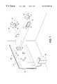
- FIG. 1schematically illustrates a tag tracking system supporting non-imaging laser tracking, as well as electromagnetic tracking and triggering using embedded antenna arrays, with specific triggering of electronic tags using a user (not shown) operable portable computer;
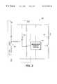
- FIG. 2schematically illustrates an optical trigger circuit for an infrared tag
- FIG. 3schematically illustrates various trigger and output circuits suitable for use in conjunction with tags according to the present invention
- FIG. 4illustrates an non-imaging laser scanning system
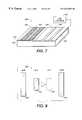
- FIG. 5illustrates a patterned retroreflective tag for use in conjunction with a non-imaging scanning laser system
- FIG. 6illustrates a dual layered patterned retroreflective tag for use in conjunction with a non-imaging scanning laser system
- FIG. 7illustrates a dual layered patterned retroreflective tag with a readily reconfigurable LCD pattern region for use in conjunction with a non-imaging scanning laser system
- FIG. 8illustrates a possible virtual control system using retroreflective tag and non-imaging scanning laser system
- FIG. 9illustrates another possible virtual control system using retroreflective tag and non-imaging scanning laser system.
- a system 10 for identification and tracking of tags distributed in a roomcan include various mechanisms for spatial localization of normally passive, normally active, or triggerable tags.
- infrared or radiofrequency electronic tagshaving a semiconductor memory for data storage, processing logic, and a small IR diode/antenna for broadcasting data, all embedded in rugged epoxy, thermoplastic, or other suitable plastic containers, is preferred.
- Data storage capacity for such electronic tagstypically ranges from a few bits to many kilobits, with 64 bits being typical.
- Tagscan include read only memory (ROM), electrically programmable or erasable (EPROM and EEPROM), or flash memory.
- An electronic tagcan be powered by a long lasting small battery, photovoltaic power, thermal converter, inductive power converter that relies on externally applied electromagnetic energy, or any other suitable power supply.
- tagscan even provide user feedback to confirm activation of the electronic tag.
- User feedbackcan be visual (e.g. blinking or turning on an LED status light, text based or iconic display presentations), auditory (e.g. an audible buzz or beep), tactile (e.g. a button being raised or a perceptible structure rotation), or combinations of the foregoing.
- Tagscan be deployed anywhere in a room. Suitable room surfaces capable of retaining objects can include but are not limited to conventional walls, ceilings, floors, pin-boards, writeable chalkboards or porcelain boards, desktops, tabletops, or even hanging tapestries. For example, tags permanently or temporarily positioned on a desktop, a wall adjacent to the desktop, or a file drawer can be detected. In other embodiments, a single wall mounted pin-board capable of holding tagged pin or clip attached objects can be used. This latter embodiment is particularly useful for use in conjunction with a single base station, since angular information alone can be used to spatially discriminate between tags. In certain embodiments particularly suitable for security monitoring, tags can be embedded in objects or otherwise not visually apparent.
- tagscan be premarked with suitable graphical, symbolic, or textual indicia.
- the tagcan be shape or texturally coded for ease of recognition.
- an electronic tag shaped as a cube or a rectangular solid with identifiable texturingcan be color coded or marked with text.
- Physical objects or artifacts suitable for tagging with passive tagsare typically documents, including but not limited to paper based textual documents, small electronic display screens, or textual material. Physical artifacts may also include wall mounted containers having signaling lights, or attachable symbolic icons.
- tagsthat can be tagged with suitable tags also include the various documents, notecards, calendars, task schedules, phone number lists, project proposals, informational flyers, meeting announcements, photographs, maps, keys, or magnetic icons commonly used to organize or disseminate information for individuals or groups.
- FIG. 1illustrates a scanning unit 20 (base station) that optionally supports comprehensive scanning of a room using laser module 26 , microwave module 28 (including radar or other beamed ranging or non-ranging electromagnetics), or acoustic module 27 (including ultrasonic or other beamed ranging or non-ranging acoustic pressure waves).
- base stationthat optionally supports comprehensive scanning of a room using laser module 26 , microwave module 28 (including radar or other beamed ranging or non-ranging electromagnetics), or acoustic module 27 (including ultrasonic or other beamed ranging or non-ranging acoustic pressure waves).
- the modulescan be gimbal 22 mounted for physical scanning of the room, or other suitable scanning mechanisms can be employed, including use of movable mirrors, diffraction gratings, phase array techniques or any other conventional mechanism for scanning a narrow beam at a known angle (with respect to a suitable coordinate system) through a room.
- multiple widely separated scanning unitscan be used to provide complete room coverage. Overlap of scanned regions by multiple scanning units further allows three-dimensional positioning when using non-ranging beams. For example, by coordinating angular positioning information from laser beams directed from scanning units 20 and 24 to be incident of a document tagged with a unique laser beam reflective tag, the system 10 can spatially localize the tag in a room.
- angular information from a single scanning unitmay be required to spatially separate tagged objects (e.g. when scanning a single wall surface, or when using phase array antenna that permits multiple portions of the array to directing multiple beams at a differing angles, providing limited triangulation for nearby microwave tags).
- multiple scanning modules integrated to share information or communicate with a common computing systemsare preferred.
- the high precision (centimeter scale localization) possible with permanently fixed scanning unitsis not required. Simple spatially localized tag activation, or relative positioning, may be all that is need.
- a portable, handheld computer 12optionally equipped with one or more optical, electromagnetic, or acoustic beam modules can be used.
- an laser 14 , ultrasonic signal generator, or radio detector/directional antenna 17can be used to project a user scannable beam that triggers, reads, activates, or otherwise interacts with tags having a unique identification.
- various detectors 16optical, infrared, radio, acoustic attached to computer 12 can be used to determine tag identity and possibly provide relative or low precision spatial localization.
- spatial localizationcan be provided without any explicit determination of beam angle.
- a tag 54 reactive to any incident laser, electromagnetic, or acoustic beamscan provide a radio data signal.
- This radio data signalcan be detected by an embedded antenna grid 40 positioned adjacent to the tag in a wallboard, chalkboard, or other suitable material.
- the x-y positional coordinates based on maximal signal strengthcan be used to determine position of the broadcasting tag.
- Identity of a tagis determined by broadcast of a suitable identifying pulse, amplitude, or frequency modulated data identifier using conventional wireless protocols.
- the system 10typically has a networked computer 30 (optionally supporting input module 32 for receiving optical, infrared, radio, or acoustic signals, as well as signals received through conventional serial, parallel, USB or other input port) supporting a software based tag tracking system for receiving input from the laser base station and the radio receiver.
- the tag tracking systemstores state records of position and informational content of the tag.
- documents 50 or 52 , or objects 54can be tagged to allow for ready manipulation of documents or artifacts through addition, removal, replacement, reordering, or stacking.
- a team's project schedulemight be represented on a wall mounted pin board by pin attached task cards arranged in a timeline format.
- Such task cardscan be easily altered or physically moved with respect to a displayed timeline as people leave a project, schedules slip, or any other problems develop.
- tagged objectsare often documents, they may alternatively be physical icons, or other small physical artifacts attachable by magnets, pins, adhesives, frictional forces, or other conventional attachment mechanisms.
- Informational content of at least some of the plurality of tagged componentscan be directly determined by transfer/reading of information (which may be either an address to an electronic document, or the document information itself) from a tag, or determined by position based associations maintained by a computer based tracking system.
- the tracking systemprovides a database with information necessary for constructing a series of time dependent snapshots of position and informational content.
- This databaseis updateable to reflect changes in position and informational content, while still retaining a time/action addressable record of state changes of the plurality of microwave tagged objects. This allows, for example, a user to digitally replay changes in a tagged object collection, or determine the state of tagged objects a day, a week, or a month earlier.
- the system 10can be used to determine identity of text or graphics on documents printed on physical media and removably attached to a surface, associating them with electronic documents accessible through networked computer.
- Other general applicationsinclude sensing the location of tagged documents or other physical artifacts, either in absolute coordinates or relative (e.g. angular differentiation) to a base station or other tagged documents.
- More advanced tracking systemscan be used to perform useful operations based on sensed actions performed by users of the system 10 , including, for example, modifications to databases based on location changes of tagged documents.
- FIG. 2shows one suitable low powered, light based trigger suitable for use in conjunction with a system 10 such as illustrated in FIG. 1 .
- a circuit 60(based on Philips BRY39 or BRY62 surface mount package) supports an IR element 64 for data broadcast. Data is stored in microcontroller 66 , and the circuit 60 is triggered to broadcast data by light hitting an LDR 62 , which in turn triggers a silicon controlled switch. Data can be broadcast using conventional IrDA standard for receipt and processing by a user's portable computer or other suitable infrared receiver/detection system.
- an intense light sourcesuch as a user pointed laser, or an automatically scannable laser such as discussed in connection with FIG. 1, is used to interrogate the circuit 60 .
- Hand holdable red lasersare particularly preferred because of their ability to create a user viewable dot aimable at a specific tag supporting low power trigger circuit 60 .
- Hand holdable lasersare compact, have a long battery life, and are widely available. Conventional hand holdable lasers can easily project a target dot having suitable intensity and size to as much as 50 feet from a user, making them ideal for pointing and triggering devices in accordance with the present invention.
- the resistance of the LDRrapidly drops below a critical threshold to trigger a silicon-controlled switch.
- an LDRchanges its resistance based on light falling on its surface, with maximal resistance for the LDR being on the order of 10 M Ohms in a dark room and 10 k Ohms in a brightly-lit room.
- a resistor or presetis place in series to control resistance values. This allows selective user adjustment of resistance values to artificially create a brighter condition than normal ambient lighting to cause the silicon-controlled switch to switch on.
- the output of the silicon-controlled switchis used to provide a reset signal to the microcontroller 66 . Because the silicon controlled switch and microcontroller typically draw less than 10 microamps in a quiescent state, battery life for the circuit is enhanced, and support for large numbers of such battery-powered devices becomes feasible.
- FIG. 3Alternative trigger modes and broadcast output modes usable in accordance with the present invention are schematically illustrated in FIG. 3 .
- a tag system 70can optionally be triggered by various trigger mechanisms 72 , including optical/infrared input (box 80 ), radiofrequency, electromagnetic or beamed microwave input (box 82 ), or acoustic/beamed ultrasonic input (box 84 ).
- Broadcast/output mechanisms 76can similarly include optical/infrared output (box 80 ), radiofrequency, electromagnetic or microwave output (box 92 ), or acoustic/ultrasonic input (box 94 ). Broadcast data is determined by a pulse train from microcontroller/data storage element 86 .
- trigger circuit 74is used to wake the microcontroller/data storage element 86 and broadcast/output mechanisms 76 from a normally quiescent, low power state that extends battery life.
- the trigger circuit 74uses a Maxim MAX837, MAX931, or equivalent that compares trigger input voltage level (e.g. light level) with a fixed reference voltage that provides a logic switching threshold.
- Supply voltagecan range from 2.5 V to 11 V, with a supply current of several microamps at 11 V.
- FIG. 4schematically illustrates a preferred laser light triggered system 100 for those embodiments of the invention requiring automatic scanning to locate or trigger tags.
- the system 100includes a laser 101 (typically near infrared, but visually perceptible laser wavelengths can be used), and a beam splitter 103 .
- laser poweris on the order of a few mW
- beam splitter 103 signal lossis on the order 3 decibels.
- low loss optical circulatorscan be substituted for beam splitter 103 .
- laser 101produces an outgoing beam directed along beam path 102 at beam splitter 103 .
- the beam splitter 103deflects half of the beam to follow beam path 106 and passes the other half along beam path 104 into a light absorber 105 .
- the beam moving along beam path 106reflects off a movable scanning mirror 107 , which is rotated by motor 108 and rotary mechanism 109 to sweep the beam around a room in a two or three dimensional sweep pattern.
- the reflected beamfollows beam path 111 to strike a retroreflective tag 110 , and returns along beam path 111 and 106 to beamsplitter 103 .
- a portion of the beampasses through the beam splitter 103 to a PIN diode 114 and amplifier 115 , permitting detection of a returned beam. If the beam returned has a recognizable data pattern, further processing can occur to determine position and object tracking and identification.
- a passive tag 120is constructed from a high gain retroreflective material 122 .
- Suitable retroreflective tag materialincludes, but is not limited to, “Reflexite”, a trademarked term of 3M Corp. that is formed as a monolayer of half silvered glass spheres carried on a flexible elastomeric substrate.
- 3M Corporations “Special Effects Projection Screen 7610”can be used. These materials-have a high degree of retroreflectivity, with incident light returned largely along its incident path with very little divergence.
- the “7610” materialhas a half power included angle of less than 1 degree, and an on-axis response 1600 times greater than a conventional white diffuser.
- parallel grooves 124are inscribed in the retroreflective material 122 of passive tag 120 , removing the half silvered glass spheres, corner reflectors, or other suitable high retroreflection material. This results in highly retroreflective lands 126 separated by minimally reflective grooves 124 . If the inscribing is done to emulate conventional bar code printing patterns, the grooves 124 correspond to black stripes, while the lands 126 are the separating white spacing stripes. Using a system such as discussed in connection with FIG. 4, the bar code-like data signal can be readily read as a laser beam sweeps across the passive tag 120 .
- a tag systemthat supports conventional bar code printing with ink, laser, or other suitable printer can be advantageous.
- a multilayer tag 130having a transparent printable cover layer 133 and a retroreflective substrate 132 (similar to that described in connection with FIG. 5) can be used.
- Conventional printing systemscan be used to print black stripes 134 across transparent cover layer 133 to emulate conventional bar code printing (or any other suitable identification scheme) by selective obscuration of the retroreflective substrate 132 .
- the bar code-like data signalcan be readily read as a laser beam sweeps across the passive tag 120 , reading the data signal in the pattern of retroreflected light signal from land area 136 separated by minimal signal from black stripes 134 .
- FIG. 7A tag system having both passive and active elements is schematically illustrated in FIG. 7 .
- a multilayer tag 140 having a transparent printable cover layer 143 and a retroreflective substrate 142can be used.
- Conventional printing systemscan be used to print black stripes.
- the bar code-like data signalcan be readily read as a laser beam sweeps across the passive tag 140 , reading the data signal in the pattern of retroreflected light signal from land area 146 separated by minimal signal from black stripes 145 .
- mutable informatione.g. shipping address, quantity of objects in tagged, opened box, etc.
- mutable informationcan be read with the aid of an active LCD layer 144 .
- dark regions 147can be formed in active LCD layer 144 to obscure the underlying retroreflective substrate 142 visible through transparent stripes 148 .
- Such a tagadvantageously allows use of preprinted identifying information, while still allowing addition of locale or object specific information in a low cost, low power tag.
- the LCD controller 149can be powered by a small battery or photovoltaic power source.
- a virtual slider control system 150can be constructed from retroreflective tags 152 , 154 , and 156 .
- the tags 152 and 154can be associated with a control system (e.g. a temperature controller, light level controller, audio level controller).
- a rotary virtual control system 160can be constructed to use relative orientation of tags 162 and rotatable “dial 164 ” as seen in conjunction with FIG. 9 .
- Such virtual control systems usable in conjunction with tags as seen in FIGS. 8 and 9 and a tracking and positioning system as discussed in connection with FIG. 1advantageously do not require direct wire connections, expensive digital or analog electronics, and can be custom designed with appropriate colored or shaped material that is suitably tagged, or is itself a tag.
- each identification number or sensed data value that is read (sensed) from the tagcan be labeled as a “command”, with a particular digital service or attribute being associated with each command.
- a sentenceis defined as a sequence of one or more temporally disjoint commands or command tuples.
- the sentence levelallows definition of an input grammar by appropriate choice of command sequence, and corollary rules governing, for example, use of active verb-like commands (e.g. “go to”, “zoom-in”, “rotate”), naming noun-like commands (e.g. DOC1.TXT, “yesterday's viewpoint” or other tag associated document, object or command), or connectors (e.g. AND).
- a tagged objectsuch as document has associated textual and electronic data is physically associated by a user with an operator icon shaped as an arrow.
- the arrow shaped objectsupports two tags having unique identification signals, allowing the arrow direction to be distinguished by the system. Placing the arrow with respect to the various tags causes modification of that associated electronic data in response to physical association of the operator icon (arrow) with a tagged object (e.g. object with embedded tag). For example, consider a situation where tagged document is positioned near an object symbolically representing a user.
- An operator icon symbolically configured as a pointing arrowcan be positioned to point from the document toward object. This association causes the database and tracking system of the system to electronically mail the document to the user. Reversal of the arrow so that the arrow points from the user symbol to the document can result in modification of document properties, linking the user in the database to the document and automatically informing the user of any updates, changes, or alterations to the document.
Landscapes
- Physics & Mathematics (AREA)
- Engineering & Computer Science (AREA)
- Electromagnetism (AREA)
- General Physics & Mathematics (AREA)
- Radar, Positioning & Navigation (AREA)
- Remote Sensing (AREA)
- Computer Networks & Wireless Communication (AREA)
- Automation & Control Theory (AREA)
- Computer Security & Cryptography (AREA)
- Radar Systems Or Details Thereof (AREA)
Abstract
Description
Claims (8)
Priority Applications (1)
| Application Number | Priority Date | Filing Date | Title |
|---|---|---|---|
| US09/448,382US6542083B1 (en) | 1999-11-23 | 1999-11-23 | Electronic tag position detection using radio broadcast |
Applications Claiming Priority (1)
| Application Number | Priority Date | Filing Date | Title |
|---|---|---|---|
| US09/448,382US6542083B1 (en) | 1999-11-23 | 1999-11-23 | Electronic tag position detection using radio broadcast |
Publications (1)
| Publication Number | Publication Date |
|---|---|
| US6542083B1true US6542083B1 (en) | 2003-04-01 |
Family
ID=23780096
Family Applications (1)
| Application Number | Title | Priority Date | Filing Date |
|---|---|---|---|
| US09/448,382Expired - LifetimeUS6542083B1 (en) | 1999-11-23 | 1999-11-23 | Electronic tag position detection using radio broadcast |
Country Status (1)
| Country | Link |
|---|---|
| US (1) | US6542083B1 (en) |
Cited By (51)
| Publication number | Priority date | Publication date | Assignee | Title |
|---|---|---|---|---|
| US20010035905A1 (en)* | 2000-04-04 | 2001-11-01 | Eric Auffret | Device for video transmission between a camera and a control room |
| US20020113773A1 (en)* | 2001-02-22 | 2002-08-22 | Mcdonnell James Thomas Edward | Electronic whiteboard |
| US20030029063A1 (en)* | 2001-08-09 | 2003-02-13 | Hitachi Electronic Service Co., Ltd. | Product label with ID chip |
| US20040011873A1 (en)* | 2002-04-11 | 2004-01-22 | Larry Canipe | System and method for optimizing range of an electronic article surveillance system |
| US20040027455A1 (en)* | 2000-12-15 | 2004-02-12 | Leonard Reiffel | Imaged coded data source tracking product |
| US6693512B1 (en)* | 2000-07-17 | 2004-02-17 | Armstrong World Industries, Inc. | Device location and identification system |
| US20040041027A1 (en)* | 2000-12-15 | 2004-03-04 | Leonard Reiffel | Imaged coded data source transducer product |
| US20040125224A1 (en)* | 2000-08-18 | 2004-07-01 | Leonard Reiffel | Annotating imaged data product |
| US20040135766A1 (en)* | 2001-08-15 | 2004-07-15 | Leonard Reiffel | Imaged toggled data input product |
| US6798349B1 (en)* | 1999-10-04 | 2004-09-28 | Xerox Corporation | Passive microwave tag identification system |
| US20040188525A1 (en)* | 2000-05-03 | 2004-09-30 | Leonard Reiffel | Dual mode data imaging product |
| US20040212504A1 (en)* | 2002-04-05 | 2004-10-28 | Beezerbug Incorporated | Ultrasonic transmitter and receiver systems and products using the same |
| US20040218273A1 (en)* | 2001-06-19 | 2004-11-04 | Ikuo Mimura | Integrated circuit enclosed retroreflective product |
| WO2004100058A1 (en)* | 2003-05-12 | 2004-11-18 | Valtion Teknillinen Tutkimuskeskus | Remote sensor, device and method for activating selected remote sensor components |
| US20050056703A1 (en)* | 2003-09-11 | 2005-03-17 | Fec Co., Ltd | IC chip for identification, data-reading method, and data-writing method |
| US20050102332A1 (en)* | 2000-12-15 | 2005-05-12 | Leonard Reiffel | Multi-imager multi-source multi-use coded data source data iInput product |
| US6892949B2 (en)* | 2000-12-29 | 2005-05-17 | Siemens Logistics And Assembly Systems Inc. | Low visual impact labeling method and system |
| US20050114760A1 (en)* | 2003-11-24 | 2005-05-26 | Xerox Corporation | Workflow system and method |
| US6909399B1 (en)* | 2003-12-31 | 2005-06-21 | Symbol Technologies, Inc. | Location system with calibration monitoring |
| US20050206504A1 (en)* | 2003-12-03 | 2005-09-22 | Fec Co., Ltd. | IC chip for identification, method for reading out data therefrom, and method for writing data thereinto |
| DE102004004587A1 (en)* | 2004-01-29 | 2005-09-22 | Rathgeber, Thomas, Dr. | Device and method for retrieving objects |
| US20050280539A1 (en)* | 2004-06-22 | 2005-12-22 | Pettus Michael G | RFID system utilizing parametric reflective technology |
| US20050285741A1 (en)* | 2004-06-29 | 2005-12-29 | Nokia Corporation | Provision of feedback to users of communication devices |
| US20060001585A1 (en)* | 2004-07-01 | 2006-01-05 | Omron Corporation | Antenna, tag communication apparatus, tag communication system, scanning adjusting method for tag communication apparatus and computer readable medium |
| US20060061481A1 (en)* | 2004-09-23 | 2006-03-23 | Kurple William M | Receptacle locator |
| US7034803B1 (en) | 2000-08-18 | 2006-04-25 | Leonard Reiffel | Cursor display privacy product |
| EP1672530A2 (en) | 2004-12-17 | 2006-06-21 | Xerox Corporation | Method and apparatus for generating instances of documents |
| US7137711B1 (en) | 2000-03-21 | 2006-11-21 | Leonard Reiffel | Multi-user retro reflector data input |
| US20060291797A1 (en)* | 2003-05-27 | 2006-12-28 | Leonard Reiffel | Multi-imager multi-source multi-use coded data source data input product |
| US20070048501A1 (en)* | 2004-04-01 | 2007-03-01 | 3M Innovative Properties Company | Formation of retroreflective sheeting with controlled cap-y |
| US20070187506A1 (en)* | 2001-04-19 | 2007-08-16 | Leonard Reiffel | Combined imaging coded data source data acquisition |
| US20080000990A1 (en)* | 2006-06-30 | 2008-01-03 | Fred Charles Thomas | Active electro-optical identification |
| US20080000976A1 (en)* | 2006-06-30 | 2008-01-03 | Fred Charles Thomas | Passive electro-optical identification |
| US20110181484A1 (en)* | 2007-06-22 | 2011-07-28 | Vubiq, Inc. | Integrated antenna and chip package and method of manufacturing thereof |
| US20110186625A1 (en)* | 2008-08-12 | 2011-08-04 | Empire Technology Development Llc | Fiducial markers for augmented reality |
| US8385461B1 (en) | 2009-04-20 | 2013-02-26 | Vubiq, Inc. | On-off keying using vector modulation |
| CN103329120A (en)* | 2010-07-29 | 2013-09-25 | 英派尔科技开发有限公司 | Fiducial markers for augmented reality |
| US9088058B2 (en) | 2009-08-19 | 2015-07-21 | Vubiq Networks, Inc. | Waveguide interface with a launch transducer and a circular interface plate |
| US20160092710A1 (en)* | 2014-09-30 | 2016-03-31 | Kyocera Document Solutions Inc. | Information acquiring method and information provision apparatus both of which are based on augmented reality |
| US9639725B1 (en) | 2015-12-16 | 2017-05-02 | General Electric Company | Tracking associate for factory and warehousing optimization |
| DE102017000130A1 (en) | 2016-01-14 | 2017-07-20 | Taoglas Group Holdings | Devices, systems and methods for aligning directional antennas |
| US10276009B2 (en) | 2017-01-26 | 2019-04-30 | Hand Held Products, Inc. | Method of reading a barcode and deactivating an electronic article surveillance tag |
| US10310052B2 (en)* | 2014-06-05 | 2019-06-04 | Zebra Technologies Corporation | Method, apparatus, and computer program product for real time location system referencing in physically and radio frequency challenged environments |
| US10320047B2 (en) | 2009-08-19 | 2019-06-11 | Vubiq Networks, Inc. | Waveguide assembly comprising a molded waveguide interface having a support block for a launch transducer that is coupled to a communication device through a flange attached to the interface |
| US10476153B2 (en) | 2015-12-22 | 2019-11-12 | Taoglas Group Holdings Limited | Directional antenna with signal strength feedback and methods |
| US10818997B2 (en) | 2017-12-29 | 2020-10-27 | Vubiq Networks, Inc. | Waveguide interface and printed circuit board launch transducer assembly and methods of use thereof |
| US10871934B2 (en) | 2017-05-04 | 2020-12-22 | Microsoft Technology Licensing, Llc | Virtual content displayed with shared anchor |
| US11216625B2 (en) | 2018-12-05 | 2022-01-04 | Vubiq Networks, Inc. | High bit density millimeter wave RFID systems, devices, and methods of use thereof |
| US11274927B2 (en)* | 2018-12-29 | 2022-03-15 | Indian Institute Of Technology Delhi | System and method for identifying passive optical identifier tags |
| US11423464B2 (en) | 2013-06-06 | 2022-08-23 | Zebra Technologies Corporation | Method, apparatus, and computer program product for enhancement of fan experience based on location data |
| US12360837B2 (en) | 2013-06-06 | 2025-07-15 | Zebra Technologies Corporation | Method, apparatus, and computer program product for collecting and displaying sporting event data based on real time data for proximity and movement of objects |
Citations (14)
| Publication number | Priority date | Publication date | Assignee | Title |
|---|---|---|---|---|
| US3591292A (en) | 1968-06-03 | 1971-07-06 | Bendix Corp | Optical control device |
| US4595915A (en)* | 1984-02-06 | 1986-06-17 | Mrs. Lawrence Israel | Electronic surveillance system employing the doppler effect |
| US4746830A (en) | 1986-03-14 | 1988-05-24 | Holland William R | Electronic surveillance and identification |
| US4940925A (en)* | 1985-08-30 | 1990-07-10 | Texas Instruments Incorporated | Closed-loop navigation system for mobile robots |
| US5134277A (en) | 1983-11-07 | 1992-07-28 | Australian Meat And Live-Stock Corporation | Remote data transfer system with ambient light insensitive circuitry |
| US5594228A (en) | 1988-08-25 | 1997-01-14 | Symbol Technologies, Inc. | Self-checkout, point-of-transaction system including deactivatable electro-optically coded surveillance tags |
| US5793630A (en)* | 1996-06-14 | 1998-08-11 | Xerox Corporation | High precision spatially defined data transfer system |
| US5825045A (en) | 1992-02-13 | 1998-10-20 | Norand Corporation | Extended range highly selective low power consuming data tag and information display system |
| US5995046A (en)* | 1998-01-30 | 1999-11-30 | Widata Corporation | Radio geo-location system with advanced first received wavefront arrival determination |
| US6008727A (en) | 1998-09-10 | 1999-12-28 | Xerox Corporation | Selectively enabled electronic tags |
| US6056199A (en) | 1995-09-25 | 2000-05-02 | Intermec Ip Corporation | Method and apparatus for storing and reading data |
| US6060992A (en)* | 1998-08-28 | 2000-05-09 | Taiwan Semiconductor Manufacturing Co., Ltd. | Method and apparatus for tracking mobile work-in-process parts |
| US6078258A (en) | 1997-07-07 | 2000-06-20 | Hi-G-Tek Ltd. | Tag system |
| JP2001216575A (en)* | 1999-11-23 | 2001-08-10 | Xerox Corp | System and method for virtual control of user operation type |
- 1999
- 1999-11-23USUS09/448,382patent/US6542083B1/ennot_activeExpired - Lifetime
Patent Citations (16)
| Publication number | Priority date | Publication date | Assignee | Title |
|---|---|---|---|---|
| US3591292A (en) | 1968-06-03 | 1971-07-06 | Bendix Corp | Optical control device |
| US5134277A (en) | 1983-11-07 | 1992-07-28 | Australian Meat And Live-Stock Corporation | Remote data transfer system with ambient light insensitive circuitry |
| US4595915A (en)* | 1984-02-06 | 1986-06-17 | Mrs. Lawrence Israel | Electronic surveillance system employing the doppler effect |
| US4940925A (en)* | 1985-08-30 | 1990-07-10 | Texas Instruments Incorporated | Closed-loop navigation system for mobile robots |
| US4746830A (en) | 1986-03-14 | 1988-05-24 | Holland William R | Electronic surveillance and identification |
| US5594228A (en) | 1988-08-25 | 1997-01-14 | Symbol Technologies, Inc. | Self-checkout, point-of-transaction system including deactivatable electro-optically coded surveillance tags |
| US5979758A (en) | 1988-08-25 | 1999-11-09 | Symbol Technologies, Inc. | Self-checkout point-of-transaction system including deactivatable electro-optically coded surveillance tags |
| US5814799A (en) | 1988-08-25 | 1998-09-29 | Symbol Technologies, Inc. | Self-checkout, point-of-transaction system including removable, electro-optically coded surveillance tags |
| US5825045A (en) | 1992-02-13 | 1998-10-20 | Norand Corporation | Extended range highly selective low power consuming data tag and information display system |
| US6056199A (en) | 1995-09-25 | 2000-05-02 | Intermec Ip Corporation | Method and apparatus for storing and reading data |
| US5793630A (en)* | 1996-06-14 | 1998-08-11 | Xerox Corporation | High precision spatially defined data transfer system |
| US6078258A (en) | 1997-07-07 | 2000-06-20 | Hi-G-Tek Ltd. | Tag system |
| US5995046A (en)* | 1998-01-30 | 1999-11-30 | Widata Corporation | Radio geo-location system with advanced first received wavefront arrival determination |
| US6060992A (en)* | 1998-08-28 | 2000-05-09 | Taiwan Semiconductor Manufacturing Co., Ltd. | Method and apparatus for tracking mobile work-in-process parts |
| US6008727A (en) | 1998-09-10 | 1999-12-28 | Xerox Corporation | Selectively enabled electronic tags |
| JP2001216575A (en)* | 1999-11-23 | 2001-08-10 | Xerox Corp | System and method for virtual control of user operation type |
Cited By (88)
| Publication number | Priority date | Publication date | Assignee | Title |
|---|---|---|---|---|
| US6798349B1 (en)* | 1999-10-04 | 2004-09-28 | Xerox Corporation | Passive microwave tag identification system |
| US7137711B1 (en) | 2000-03-21 | 2006-11-21 | Leonard Reiffel | Multi-user retro reflector data input |
| US20010035905A1 (en)* | 2000-04-04 | 2001-11-01 | Eric Auffret | Device for video transmission between a camera and a control room |
| US7030906B2 (en)* | 2000-04-14 | 2006-04-18 | Thomson Licensing | Device for video transmission between a camera and a control room |
| US7000840B2 (en)* | 2000-05-03 | 2006-02-21 | Leonard Reiffel | Dual mode data imaging product |
| US20040188525A1 (en)* | 2000-05-03 | 2004-09-30 | Leonard Reiffel | Dual mode data imaging product |
| US6693512B1 (en)* | 2000-07-17 | 2004-02-17 | Armstrong World Industries, Inc. | Device location and identification system |
| US20040125224A1 (en)* | 2000-08-18 | 2004-07-01 | Leonard Reiffel | Annotating imaged data product |
| US7161581B2 (en) | 2000-08-18 | 2007-01-09 | Leonard Reiffel | Annotating imaged data product |
| US7034803B1 (en) | 2000-08-18 | 2006-04-25 | Leonard Reiffel | Cursor display privacy product |
| US6945460B2 (en) | 2000-12-15 | 2005-09-20 | Leonard Reiffel | Imaged coded data source transducer product |
| US20040041027A1 (en)* | 2000-12-15 | 2004-03-04 | Leonard Reiffel | Imaged coded data source transducer product |
| US20040027455A1 (en)* | 2000-12-15 | 2004-02-12 | Leonard Reiffel | Imaged coded data source tracking product |
| US7184075B2 (en) | 2000-12-15 | 2007-02-27 | Leonard Reiffel | Imaged coded data source tracking product |
| US7099070B2 (en) | 2000-12-15 | 2006-08-29 | Leonard Reiffel | Multi-imager multi-source multi-use coded data source data input product |
| US20050102332A1 (en)* | 2000-12-15 | 2005-05-12 | Leonard Reiffel | Multi-imager multi-source multi-use coded data source data iInput product |
| US6892949B2 (en)* | 2000-12-29 | 2005-05-17 | Siemens Logistics And Assembly Systems Inc. | Low visual impact labeling method and system |
| US20020113773A1 (en)* | 2001-02-22 | 2002-08-22 | Mcdonnell James Thomas Edward | Electronic whiteboard |
| US20070187506A1 (en)* | 2001-04-19 | 2007-08-16 | Leonard Reiffel | Combined imaging coded data source data acquisition |
| US7377438B2 (en) | 2001-04-19 | 2008-05-27 | Leonard Reiffel | Combined imaging coded data source data acquisition |
| US7224279B2 (en)* | 2001-06-19 | 2007-05-29 | Nippon Carbide Kogyo Kabushiki Kaisha | Integrated circuit enclosed retroreflective product |
| US7598874B2 (en) | 2001-06-19 | 2009-10-06 | Nippon Carbide Kogyo Kabushiki Kaisha | Integrated-circuit enclosed retroreflective product |
| US20070194133A1 (en)* | 2001-06-19 | 2007-08-23 | Nippon Carbide Kogyo Kabushiki Kaisha | Integrated-circuit enclosed retroreflective product |
| US20040218273A1 (en)* | 2001-06-19 | 2004-11-04 | Ikuo Mimura | Integrated circuit enclosed retroreflective product |
| US20030029063A1 (en)* | 2001-08-09 | 2003-02-13 | Hitachi Electronic Service Co., Ltd. | Product label with ID chip |
| US20040135766A1 (en)* | 2001-08-15 | 2004-07-15 | Leonard Reiffel | Imaged toggled data input product |
| US20040212504A1 (en)* | 2002-04-05 | 2004-10-28 | Beezerbug Incorporated | Ultrasonic transmitter and receiver systems and products using the same |
| US7498946B2 (en) | 2002-04-05 | 2009-03-03 | Beezerbug Incorporated | Ultrasonic transmitter and receiver systems and products using the same |
| US20060181421A1 (en)* | 2002-04-05 | 2006-08-17 | Beezerbug Incorporated | Ultrasonic transmitter and receiver systems and products using the same |
| US7061381B2 (en)* | 2002-04-05 | 2006-06-13 | Beezerbug Incorporated | Ultrasonic transmitter and receiver systems and products using the same |
| US20040011873A1 (en)* | 2002-04-11 | 2004-01-22 | Larry Canipe | System and method for optimizing range of an electronic article surveillance system |
| US7316355B2 (en)* | 2002-04-11 | 2008-01-08 | Sensormatic Electronics Corporation | System and method for optimizing range of an electronic article surveillance system |
| US7671721B2 (en) | 2003-05-12 | 2010-03-02 | Valtion Teknillinen Tutkimuskesus | Remote sensor, device and method for activating selected remote sensor components |
| WO2004100058A1 (en)* | 2003-05-12 | 2004-11-18 | Valtion Teknillinen Tutkimuskeskus | Remote sensor, device and method for activating selected remote sensor components |
| US20060202802A1 (en)* | 2003-05-12 | 2006-09-14 | Seppae Heikki | Remote sensor, device and method for activating selected remote sensor components |
| US20060291797A1 (en)* | 2003-05-27 | 2006-12-28 | Leonard Reiffel | Multi-imager multi-source multi-use coded data source data input product |
| US20050056703A1 (en)* | 2003-09-11 | 2005-03-17 | Fec Co., Ltd | IC chip for identification, data-reading method, and data-writing method |
| US7511605B2 (en)* | 2003-09-11 | 2009-03-31 | Fec Co., Ltd. | IC chip for identification, data-reading method, and data-writing method |
| US20050114760A1 (en)* | 2003-11-24 | 2005-05-26 | Xerox Corporation | Workflow system and method |
| US7577706B2 (en) | 2003-11-24 | 2009-08-18 | Xerox Corporation | Integrating a document management system with a workflow system and method |
| US20050206504A1 (en)* | 2003-12-03 | 2005-09-22 | Fec Co., Ltd. | IC chip for identification, method for reading out data therefrom, and method for writing data thereinto |
| US7598864B2 (en)* | 2003-12-03 | 2009-10-06 | Fec Co., Ltd. | IC chip for identification, method for reading out data therefrom, and method for writing data thereinto |
| US6909399B1 (en)* | 2003-12-31 | 2005-06-21 | Symbol Technologies, Inc. | Location system with calibration monitoring |
| US20050146464A1 (en)* | 2003-12-31 | 2005-07-07 | Chris Zegelin | Location system with calibration monitoring |
| WO2005066655A1 (en)* | 2003-12-31 | 2005-07-21 | Symbol Technologies, Inc. | Location system with calibration monitoring |
| DE102004004587A1 (en)* | 2004-01-29 | 2005-09-22 | Rathgeber, Thomas, Dr. | Device and method for retrieving objects |
| DE102004004587B4 (en)* | 2004-01-29 | 2005-12-22 | Rathgeber, Thomas, Dr. | Device and method for retrieving objects |
| US20070048501A1 (en)* | 2004-04-01 | 2007-03-01 | 3M Innovative Properties Company | Formation of retroreflective sheeting with controlled cap-y |
| US7498940B2 (en)* | 2004-06-22 | 2009-03-03 | Vubiq, Inc. | RFID system utilizing parametric reradiated technology |
| US20050280504A1 (en)* | 2004-06-22 | 2005-12-22 | Vubiq Incorporated, A Nevada Corporation | RFID system utilizing parametric reflective technology |
| US7460014B2 (en) | 2004-06-22 | 2008-12-02 | Vubiq Incorporated | RFID system utilizing parametric reflective technology |
| US20050280539A1 (en)* | 2004-06-22 | 2005-12-22 | Pettus Michael G | RFID system utilizing parametric reflective technology |
| US20050285741A1 (en)* | 2004-06-29 | 2005-12-29 | Nokia Corporation | Provision of feedback to users of communication devices |
| US7212119B2 (en)* | 2004-06-29 | 2007-05-01 | Nokia Corporation | Provision of feedback to users of communication devices |
| US7724140B2 (en)* | 2004-07-01 | 2010-05-25 | Omron Corporation | Antenna, tag communication apparatus, tag communication system, scanning adjusting method for tag communication apparatus and computer readable medium |
| US20060001585A1 (en)* | 2004-07-01 | 2006-01-05 | Omron Corporation | Antenna, tag communication apparatus, tag communication system, scanning adjusting method for tag communication apparatus and computer readable medium |
| US20060061481A1 (en)* | 2004-09-23 | 2006-03-23 | Kurple William M | Receptacle locator |
| US8108773B2 (en) | 2004-12-17 | 2012-01-31 | Xerox Corporation | Method and apparatus for generating instances of documents |
| EP1672530A2 (en) | 2004-12-17 | 2006-06-21 | Xerox Corporation | Method and apparatus for generating instances of documents |
| US20080000990A1 (en)* | 2006-06-30 | 2008-01-03 | Fred Charles Thomas | Active electro-optical identification |
| US7874490B2 (en)* | 2006-06-30 | 2011-01-25 | Britta Technologies, Llc | Active electro-optical identification |
| US20080000976A1 (en)* | 2006-06-30 | 2008-01-03 | Fred Charles Thomas | Passive electro-optical identification |
| US8113434B2 (en) | 2006-06-30 | 2012-02-14 | Britta Technologies, Llc | Passive electro-optical identification tags |
| US8477070B2 (en) | 2007-06-22 | 2013-07-02 | Vubiq, Inc. | Integrated antenna and chip package and method of manufacturing thereof |
| US20110181484A1 (en)* | 2007-06-22 | 2011-07-28 | Vubiq, Inc. | Integrated antenna and chip package and method of manufacturing thereof |
| US8434674B2 (en) | 2008-08-12 | 2013-05-07 | Empire Technology Development Llc | Fiducial markers for augmented reality |
| US20110186625A1 (en)* | 2008-08-12 | 2011-08-04 | Empire Technology Development Llc | Fiducial markers for augmented reality |
| US8385461B1 (en) | 2009-04-20 | 2013-02-26 | Vubiq, Inc. | On-off keying using vector modulation |
| US9088058B2 (en) | 2009-08-19 | 2015-07-21 | Vubiq Networks, Inc. | Waveguide interface with a launch transducer and a circular interface plate |
| US10320047B2 (en) | 2009-08-19 | 2019-06-11 | Vubiq Networks, Inc. | Waveguide assembly comprising a molded waveguide interface having a support block for a launch transducer that is coupled to a communication device through a flange attached to the interface |
| CN103329120A (en)* | 2010-07-29 | 2013-09-25 | 英派尔科技开发有限公司 | Fiducial markers for augmented reality |
| WO2012015405A3 (en)* | 2010-07-29 | 2014-03-20 | Empire Technology Development Llc | Fiducial markers for augmented reality |
| US12360837B2 (en) | 2013-06-06 | 2025-07-15 | Zebra Technologies Corporation | Method, apparatus, and computer program product for collecting and displaying sporting event data based on real time data for proximity and movement of objects |
| US11423464B2 (en) | 2013-06-06 | 2022-08-23 | Zebra Technologies Corporation | Method, apparatus, and computer program product for enhancement of fan experience based on location data |
| US10310052B2 (en)* | 2014-06-05 | 2019-06-04 | Zebra Technologies Corporation | Method, apparatus, and computer program product for real time location system referencing in physically and radio frequency challenged environments |
| US10942248B2 (en) | 2014-06-05 | 2021-03-09 | Zebra Technologies Corporation | Method, apparatus, and computer program product for real time location system referencing in physically and radio frequency challenged environments |
| US9483676B2 (en)* | 2014-09-30 | 2016-11-01 | Kyocera Document Solutions Inc. | Information acquiring method and information provision apparatus both of which are based on augmented reality |
| US20160092710A1 (en)* | 2014-09-30 | 2016-03-31 | Kyocera Document Solutions Inc. | Information acquiring method and information provision apparatus both of which are based on augmented reality |
| US9639725B1 (en) | 2015-12-16 | 2017-05-02 | General Electric Company | Tracking associate for factory and warehousing optimization |
| US10476153B2 (en) | 2015-12-22 | 2019-11-12 | Taoglas Group Holdings Limited | Directional antenna with signal strength feedback and methods |
| US11088446B2 (en) | 2015-12-22 | 2021-08-10 | Taoglas Group Holdings Limited | Directional antenna with signal strength feedback and methods |
| US11688940B2 (en) | 2015-12-22 | 2023-06-27 | Taoglas Group Holdings Limited | Directional antenna with signal strength feedback and methods |
| DE102017000130A1 (en) | 2016-01-14 | 2017-07-20 | Taoglas Group Holdings | Devices, systems and methods for aligning directional antennas |
| US10276009B2 (en) | 2017-01-26 | 2019-04-30 | Hand Held Products, Inc. | Method of reading a barcode and deactivating an electronic article surveillance tag |
| US10871934B2 (en) | 2017-05-04 | 2020-12-22 | Microsoft Technology Licensing, Llc | Virtual content displayed with shared anchor |
| US10818997B2 (en) | 2017-12-29 | 2020-10-27 | Vubiq Networks, Inc. | Waveguide interface and printed circuit board launch transducer assembly and methods of use thereof |
| US11216625B2 (en) | 2018-12-05 | 2022-01-04 | Vubiq Networks, Inc. | High bit density millimeter wave RFID systems, devices, and methods of use thereof |
| US11274927B2 (en)* | 2018-12-29 | 2022-03-15 | Indian Institute Of Technology Delhi | System and method for identifying passive optical identifier tags |
Similar Documents
| Publication | Publication Date | Title |
|---|---|---|
| US6542083B1 (en) | Electronic tag position detection using radio broadcast | |
| US7229017B2 (en) | Laser locating and tracking system for externally activated tags | |
| RU2332712C2 (en) | Device possessing light reflecting properties and emission of response radio signal | |
| CN104392196B (en) | The remote selective RFID waken up is detected using laser optical | |
| CN1934459B (en) | Wireless location and identification system and method | |
| US7855643B2 (en) | Tracking systems, passive RFIDs, methods of locating and identifying RFIDs, and methods of tracking items | |
| US8434674B2 (en) | Fiducial markers for augmented reality | |
| JP4541465B2 (en) | Electronic tag, electronic tag identification system | |
| US20070140095A1 (en) | Enhanced electronic ink displays | |
| US6078258A (en) | Tag system | |
| JP4786716B2 (en) | Operation tool comprising a conductor piece | |
| JP4618401B2 (en) | Information display system and information display method | |
| CN1980084A (en) | Position locator for locating position of rfid tag | |
| JP2009020813A (en) | Tag and article identification system using the same | |
| AU2005290086A1 (en) | A passport reader for processing a passport having an RFID element | |
| US6798349B1 (en) | Passive microwave tag identification system | |
| EP1103824A2 (en) | Virtual control system using non-imaging scanners | |
| CN103329120A (en) | Fiducial markers for augmented reality | |
| EP1103914A1 (en) | Patterned retroreflective tags usable in laser scanning systems | |
| US9555320B2 (en) | System and method to identify and track objects on a surface | |
| CN102103682B (en) | Electronic scanning article search system and assorted electronic tag thereof | |
| US7089288B2 (en) | Interactive context preserved navigation of graphical data sets using multiple physical tags | |
| JP4664012B2 (en) | Directional optical ID device and optical ID tag | |
| JP2016122479A (en) | Electronic tag system | |
| Raskar et al. | Photosensing wireless tags for geometric procedures |
Legal Events
| Date | Code | Title | Description |
|---|---|---|---|
| AS | Assignment | Owner name:XEROX CORPORATION, CONNECTICUT Free format text:ASSIGNMENT OF ASSIGNORS INTEREST;ASSIGNORS:RICHLEY, EDWARD A.;WANT, ROY;FISHKIN, KENNETH P.;AND OTHERS;REEL/FRAME:010707/0989;SIGNING DATES FROM 20000222 TO 20000301 | |
| AS | Assignment | Owner name:BANK ONE, NA, AS ADMINISTRATIVE AGENT, ILLINOIS Free format text:SECURITY AGREEMENT;ASSIGNOR:XEROX CORPORATION;REEL/FRAME:013111/0001 Effective date:20020621 Owner name:BANK ONE, NA, AS ADMINISTRATIVE AGENT,ILLINOIS Free format text:SECURITY AGREEMENT;ASSIGNOR:XEROX CORPORATION;REEL/FRAME:013111/0001 Effective date:20020621 | |
| STCF | Information on status: patent grant | Free format text:PATENTED CASE | |
| AS | Assignment | Owner name:JPMORGAN CHASE BANK, AS COLLATERAL AGENT, TEXAS Free format text:SECURITY AGREEMENT;ASSIGNOR:XEROX CORPORATION;REEL/FRAME:015134/0476 Effective date:20030625 Owner name:JPMORGAN CHASE BANK, AS COLLATERAL AGENT,TEXAS Free format text:SECURITY AGREEMENT;ASSIGNOR:XEROX CORPORATION;REEL/FRAME:015134/0476 Effective date:20030625 | |
| FPAY | Fee payment | Year of fee payment:4 | |
| AS | Assignment | Owner name:XEROX CORPORATION, NEW YORK Free format text:RELEASE BY SECURED PARTY;ASSIGNOR:JP MORGAN CHASE BANK, NA;REEL/FRAME:019872/0199 Effective date:20061204 | |
| AS | Assignment | Owner name:XEROX CORPORATION, NEW YORK Free format text:RELEASE BY SECURED PARTY;ASSIGNOR:BANK ONE, NA;REEL/FRAME:019896/0303 Effective date:20020621 | |
| AS | Assignment | Owner name:XEROX CORPORATION, NEW YORK Free format text:CORRECTIVE ASSIGNMENT TO CORRECT THE EXECUTION DATE PREVIOUSLY RECORDED ON REEL 019896 FRAME 0303;ASSIGNOR:BANK ONE, NA;REEL/FRAME:019913/0041 Effective date:20030625 | |
| AS | Assignment | Owner name:MILLSTONE TRANSFER AG, L.L.C., DELAWARE Free format text:ASSIGNMENT OF ASSIGNORS INTEREST;ASSIGNOR:XEROX CORPORATION;REEL/FRAME:020243/0826 Effective date:20071130 | |
| FPAY | Fee payment | Year of fee payment:8 | |
| FEPP | Fee payment procedure | Free format text:PAYOR NUMBER ASSIGNED (ORIGINAL EVENT CODE: ASPN); ENTITY STATUS OF PATENT OWNER: LARGE ENTITY | |
| FPAY | Fee payment | Year of fee payment:12 | |
| AS | Assignment | Owner name:CHARTOLEAUX KG LIMITED LIABILITY COMPANY, DELAWARE Free format text:MERGER;ASSIGNOR:MILLSTONE TRANSFER AG, L.L.C.;REEL/FRAME:037274/0824 Effective date:20150812 | |
| AS | Assignment | Owner name:XEROX CORPORATION, CONNECTICUT Free format text:RELEASE BY SECURED PARTY;ASSIGNOR:JPMORGAN CHASE BANK, N.A. AS SUCCESSOR-IN-INTEREST ADMINISTRATIVE AGENT AND COLLATERAL AGENT TO BANK ONE, N.A.;REEL/FRAME:061388/0388 Effective date:20220822 Owner name:XEROX CORPORATION, CONNECTICUT Free format text:RELEASE BY SECURED PARTY;ASSIGNOR:JPMORGAN CHASE BANK, N.A. AS SUCCESSOR-IN-INTEREST ADMINISTRATIVE AGENT AND COLLATERAL AGENT TO JPMORGAN CHASE BANK;REEL/FRAME:066728/0193 Effective date:20220822 |