US6541836B2 - Semiconductor radiation detector with internal gain - Google Patents
Semiconductor radiation detector with internal gainDownload PDFInfo
- Publication number
- US6541836B2 US6541836B2US09/835,829US83582901AUS6541836B2US 6541836 B2US6541836 B2US 6541836B2US 83582901 AUS83582901 AUS 83582901AUS 6541836 B2US6541836 B2US 6541836B2
- Authority
- US
- United States
- Prior art keywords
- electrode
- radiation
- avalanche
- region
- radiation detector
- Prior art date
- Legal status (The legal status is an assumption and is not a legal conclusion. Google has not performed a legal analysis and makes no representation as to the accuracy of the status listed.)
- Expired - Fee Related, expires
Links
Images


Classifications
- H—ELECTRICITY
- H10—SEMICONDUCTOR DEVICES; ELECTRIC SOLID-STATE DEVICES NOT OTHERWISE PROVIDED FOR
- H10F—INORGANIC SEMICONDUCTOR DEVICES SENSITIVE TO INFRARED RADIATION, LIGHT, ELECTROMAGNETIC RADIATION OF SHORTER WAVELENGTH OR CORPUSCULAR RADIATION
- H10F30/00—Individual radiation-sensitive semiconductor devices in which radiation controls the flow of current through the devices, e.g. photodetectors
- H10F30/20—Individual radiation-sensitive semiconductor devices in which radiation controls the flow of current through the devices, e.g. photodetectors the devices having potential barriers, e.g. phototransistors
- H10F30/21—Individual radiation-sensitive semiconductor devices in which radiation controls the flow of current through the devices, e.g. photodetectors the devices having potential barriers, e.g. phototransistors the devices being sensitive to infrared, visible or ultraviolet radiation
- H10F30/22—Individual radiation-sensitive semiconductor devices in which radiation controls the flow of current through the devices, e.g. photodetectors the devices having potential barriers, e.g. phototransistors the devices being sensitive to infrared, visible or ultraviolet radiation the devices having only one potential barrier, e.g. photodiodes
- H10F30/225—Individual radiation-sensitive semiconductor devices in which radiation controls the flow of current through the devices, e.g. photodetectors the devices having potential barriers, e.g. phototransistors the devices being sensitive to infrared, visible or ultraviolet radiation the devices having only one potential barrier, e.g. photodiodes the potential barrier working in avalanche mode, e.g. avalanche photodiodes
- H—ELECTRICITY
- H10—SEMICONDUCTOR DEVICES; ELECTRIC SOLID-STATE DEVICES NOT OTHERWISE PROVIDED FOR
- H10F—INORGANIC SEMICONDUCTOR DEVICES SENSITIVE TO INFRARED RADIATION, LIGHT, ELECTROMAGNETIC RADIATION OF SHORTER WAVELENGTH OR CORPUSCULAR RADIATION
- H10F39/00—Integrated devices, or assemblies of multiple devices, comprising at least one element covered by group H10F30/00, e.g. radiation detectors comprising photodiode arrays
- H10F39/10—Integrated devices
- H10F39/12—Image sensors
- H10F39/18—Complementary metal-oxide-semiconductor [CMOS] image sensors; Photodiode array image sensors
- H—ELECTRICITY
- H10—SEMICONDUCTOR DEVICES; ELECTRIC SOLID-STATE DEVICES NOT OTHERWISE PROVIDED FOR
- H10F—INORGANIC SEMICONDUCTOR DEVICES SENSITIVE TO INFRARED RADIATION, LIGHT, ELECTROMAGNETIC RADIATION OF SHORTER WAVELENGTH OR CORPUSCULAR RADIATION
- H10F39/00—Integrated devices, or assemblies of multiple devices, comprising at least one element covered by group H10F30/00, e.g. radiation detectors comprising photodiode arrays
- H10F39/80—Constructional details of image sensors
- H—ELECTRICITY
- H10—SEMICONDUCTOR DEVICES; ELECTRIC SOLID-STATE DEVICES NOT OTHERWISE PROVIDED FOR
- H10F—INORGANIC SEMICONDUCTOR DEVICES SENSITIVE TO INFRARED RADIATION, LIGHT, ELECTROMAGNETIC RADIATION OF SHORTER WAVELENGTH OR CORPUSCULAR RADIATION
- H10F71/00—Manufacture or treatment of devices covered by this subclass
Definitions
- the present inventionis related to detection of radiation, and particularly, to a semiconductor radiation detector having internal gain.
- Gamma ray spectroscopy using scintillation detectorstypically employs scintillators coupled to photomultiplier tubes (PMTs). Scintillator/PMT systems offer excellent efficiency with moderate energy resolution. These systems have drawbacks, however, particularly regarding the PMT light sensor.
- the PMTis a bulky and fragile component. It is vulnerable to damage, has low and non-uniform quantum efficiency, requires a stabilized high voltage for operation, and lacks immunity from magnetic fields. Consequently, it has been an ongoing quest to find suitable alternatives to replace either the PMT, or the entire scintillator/PMT system, for gamma-ray spectrometry.
- Such detectorsare needed for applications such as gamma ray spectroscopy, photon counting, gamma ray counting, and gamma ray imaging.
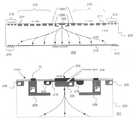
- FIG. 1shows a schematic diagram (right) of a conventional PMT-based gamma camera 100 .
- the PMT-based gamma camera 100includes a parallel-hole collimator 104 , a scintillation crystal (typically CsI[Tl] or NaI[Tl]) 106 , a light diffuser 108 , an array of photomultiplier tubes (PMTs) 112 , and a position/pulse-height module 114 which performs position arithmetic and spectrometric functions, all enclosed by a lead shield 102 .
- a scintillation crystaltypically CsI[Tl] or NaI[Tl]
- PMTsphotomultiplier tubes
- the position/pulse-height module 114may include analog electronics and may also include one or more analog-to-digital converters (ADCs) for ADC conversion of analog signals at the front end.
- ADCsanalog-to-digital converters
- FIG. 1also shows a schematic diagram (left) of a solid state photodetector-based gamma camera 120 .
- the solid state photodetector-based gamma camera 120includes a parallel-hole collimator 124 , a scintillation crystal (typically CsI[Tl] or NaI[TL]) 126 , a light diffuser 128 , solid state photodetectors 132 on substrate 134 , and a position/pulse-height module 136 , all enclosed by a lead shield 122 .
- the solid state photodetector-based gamma camera 120may also be referred to as a solid state gamma camera.
- Solid state gamma camerashave drawn a lot of interest because they may offer potential improvements in performance. Since the energy resolution of scintillation spectrometers depends primarily on the number of scintillation photons collected, the high quantum efficiency, high response uniformity, and low electronic noise of the solid state detectors should provide better energy resolution than current technologies.
- an Anger type scintillation cameratypically depends on the spacing between the photodetectors and the signal-to-noise ratio (SNR) of the photodetectors
- SNRsignal-to-noise ratio
- the replacement of the photomultiplier tube with a solid state photodetector of just a few hundred microns thicknesscould lead to a more compact system with a significant reduction in shielding mass.
- the lead shield 122 of the solid state gamma camera 120is significantly smaller in size than the lead shield 102 of the PMT based gamma camera 100 .
- the reduction in shielding masswould allow the development of lighter scintillation cameras that could be accommodated in new types of gantrys or frames. This could open up the possibility of other uses in surgeries to help locate lesion sites or in research laboratories.
- Solid state photodetector signalsare typically more naturally interfaced to the digital domain leading to integrated/smart detectors with much more up-front processing capability resulting in improved performance and lower cost. They are typically amenable to digital signal processing, leading to improved energy performance afforded by more optimal signal shaping such as real-time adaptive filter pulse shaping, which can optimize shaping time based on instantaneous throughput. They may also provide higher throughput due to capability of replacing analog pulse shaping with digital filters incorporating schemes such as real-time adaptive filter pulse shaping described above.
- Si-PIN photodetector-based gamma camerasAn even greater challenge to the widespread use of the Si-PIN photodetector-based gamma cameras may be that the intrinsic detector noise is quite high for photodetectors above a few square millimeters in area.
- the Si-PIN photodetectorsare usually pixelated to just a few square mm per pixel, and each pixel typically requires a separate electronic readout channel.
- a 25 cm by 20 cm gamma camera based on an array of 3 ⁇ 3 mm 2 pixelsrequires 5555 channels of readout electronics. This is a major disadvantage compared to any detector architecture that can take advantage of sparse readout schemes, such as Anger logic.
- APDavalanche photodetectors
- CZTis an interesting material for gamma camera construction because of its high average atomic number, which makes it highly absorbing of gamma rays, and because of its large bandgap, which gives it good spectroscopic capabilities and room temperature operation.
- CZTis still a very exotic material that is extremely expensive to produce and remains unproven in the commercial marketplace.
- the medical applicationsmay require performance at the limit of the capabilities of the material.
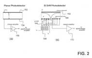
- FIG. 2shows a comparison between cross sections of a standard planar photodetector 150 and an SDP 160 .
- the standard planar photodetector 150includes an entrance electrode 152 , an anode 154 and a charge amplifier 156 .
- FIG. 2shows that the anode 154 is similar in size to the entrance electrode 152 .
- the SDP 160includes an entrance electrode 162 , an anode 164 , steering electrodes 166 , a resistor ladder 168 for biasing the steering electrodes and a standard charge amplifier 170 . Due to drift of charge carriers caused by biasing of the steering electrodes 166 , the anode 164 can be significantly smaller in size than the entrance electrode 162 .
- the SDP coupled to scintillatorsis disclosed in International Patent Application No. PCT/US99/26524 entitled “Gamma-Ray Detector Employing Scintillators Coupled to Semiconductor Drift Photodetectors,” filed Nov. 9, 1999, the contents of which are incorporated by reference in full herein. Thus, embodiments of the present invention may employ various different methods and structures disclosed in International Patent Application No. PCT/US99/26524.
- the small detector capacitanceis independent of the overall detector size. Reduction in the detector capacitance can potentially lead to significant reduction in the series noise and hence the overall detector noise.
- the first stage of the electronicsneeds to also have a similar low input capacitance and minimum stray capacitance.
- One way to achieve thisis by integrating the first stage of the electronics, e.g., field effect transistor (FET) into the detector anode.
- FETfield effect transistor
- the integrated FET processis not compatible with high resistivity silicon detector process, typically allowing only for construction of structures with highly simplified configurations in comparison to the commercially available low noise junction FETs (JFETs). Moreover, the improvement that can be obtained with the integrated FET typically is most marked at short shaping times, which is undesirable for applications with long decay time scintillators such as CsI[Tl], which has a 1.1 ⁇ S decay time.
- TECthermoelectric cooling
- Use of coolingtypically requires heat transfer stages, and thus increases size and cost of gamma cameras.
- a radiation detector formed on a semiconductor material having first and second surfacesis provided.
- the radiation detectoris used to receive radiation and to generate a detector signal.
- the radiation detectorincludes a first electrode, a second electrode and a plurality of steering electrodes.
- the first electrodeis formed on the first surface and is used to receive the radiation.
- the received radiationcauses mobile electrical charges to be produced in the radiation detector.
- the second electrodeis formed on the second surface and is used to collect at least a portion of the mobile electrical charges.
- the second electrodeis significantly smaller in size than the first electrode.
- the plurality of steering electrodesare formed on the second surface around the second electrode and are used to steer the mobile electrical charges towards the second electrode.
- the second electrodecomprises an avalanche region functioning as an avalanche multiplication stage. The mobile electrical charges are multiplied in the avalanche region and collected at the second electrode.
- a gamma cameracomprising one or more solid state photodetectors is provided.
- a gamma ray detectorcomprising one or more solid state photodetectors is provided.
- a detector for detecting individual photonsincludes a scintillator and an avalanche drift photodetector (ADP) optically coupled to the scintillator.
- ADPavalanche drift photodetector
- an imaging detectorfor detecting individual photons.
- the imaging detectorincludes a scintillator array comprising a plurality of segments and a photodetector array comprising a plurality of avalanche drift photodetectors (ADPs).
- ADPsavalanche drift photodetectors
- a detector formed on a semiconductor materialincludes an avalanche region for multiplying a detector signal generated within the detector in response to an input stimulus.
- the surface of the avalanche regionis substantially smaller in size than the detector surface used to receive the input stimulus.
- the avalanche regionis used to multiply the detector signal without multiplying surface leakage current.
- a method of forming a solid state detector on an n-type semiconductor substrateis provided.
- a first part of p+ anode guardis inserted into the n-type semiconductor substrate.
- a first high resistivity n-type epitaxial layeris deposited on the n-type semiconductor substrate.
- a p+ avalanche region and a second part of p+ anode guardare inserted into the first high resistivity n-type epitaxial layer.
- a first n+guardis inserted into the first high resistivity n-type epitaxial layer.
- a second high resistivity n-type epitaxial layeris deposited on the first high resistivity n-type epitaxial layer.
- n+anode and a second n+guardare inserted into the second high resistivity n-type epitaxial layer.
- a third part of p+ anode guard and a plurality of p+ ringsare inserted into the second high resistivity n-type epitaxial layer.
- a method of forming a solid state detector on an n-type semiconductor substrateis provided.
- a first part of p+ anode guardis inserted into the semiconductor substrate.
- a p+ wellis formed by driving p+ dopant into the n-type semiconductor substrate.
- a p+ avalanche regionis inserted into the semiconductor substrate.
- a n+guardis inserted into the p+ well.
- the p+ wellis enlarged by further driving p+ dopant into the n-type semiconductor substrate.
- a plurality of p+ ringsare inserted into the n-type semiconductor substrate.
- An n+ anodeis inserted into the semiconductor substrate.
- FIG. 1shows a comparison between a standard PMT based gamma camera (right) and a solid state photodetector-based scintillation camera (left), which may incorporate an embodiment according to the present invention
- FIG. 2shows a comparison between cross sections of standard planar diode photodetector (left) and Silicon drift photodetector (SDP) (right);
- FIGS. 3A and 3Bare a cross-sectional schematic views of an ADP and magnified schematic of an avalanche anode region in an embodiment according to the present invention
- FIG. 4illustrates a cross-sectional view of the simulated anode region dopant distribution
- FIG. 5illustrates a cross-sectional view of the simulated E-field magnitude distribution in the anode region
- FIG. 6illustrates a cross-sectional view of the simulated radial distribution of E-field magnitude at a few micron depth (in the middle of the avalanche region);
- FIG. 7illustrates a cross-sectional view of the simulated potential distribution in the anode region with electron drift trajectory
- FIGS. 8A, 8 B and 8 Cillustrate an epitaxial process for fabricating ADPs in an embodiment according to the present invention
- FIG. 9is a flow diagram illustrating the epitaxial process for fabricating ADPs as illustrated in FIGS. 8A, 8 B and 8 C;
- FIGS. 10A, 10 B and 10 Cillustrate a diffusive process for fabricating ADPs in another embodiment according to the present invention
- FIG. 11is a flow diagram illustrating the diffusive process for fabricating ADPs as illustrated in FIGS. 10A, 10 B and 10 C;
- FIG. 12is a graph of calculated electronic noise ( ⁇ E/E [% FWHM]) vs. peaking time for 140 keV photons for the following four scenarios:
- One embodiment of the present inventionprovides for a silicon avalanche drift photodetector (ADP) for applications including, but not limited to, gamma ray spectroscopy, photon counting, gamma ray counting, and gamma ray imaging.
- the ADPmay be used to count individual gamma ray photons and to perform spectroscopy.
- the ADPmay also be used to count light photons individually, especially when used in conjunction with scintillators with long decay times, such as, for example, CsI[Tl].
- the ADPhas both the small anode capacitance of an SDP and the internal gain of the detector signal (and not the surface leakage current) of an APD.
- Electrons, created by ionization event,are focused from a large area into a small (100-200 ⁇ m diameter) anode, similar to the case of SDPs;
- the required E-field magnitude in the avalanche regionis approximately 300 kV/cm in order to allow for electron impact ionization (multiplication gain);
- E-field magnitudehas fairly uniform radial distribution within the anode region, possibly being slightly stronger near the anode center;
- the doping profilemay be achieved using standard planar processing techniques.
- the E-field magnitude at the electrode edgestended to be orders of magnitude higher than in the regions above the electrodes.
- the oppositeis true, i.e., the E-field above the planar anode is about two orders of magnitude higher than it is in a typical SDP, without substantially increasing the field at the anode edges.
- the overall structure of an ADP 200is shown in FIG. 3 A.
- the ADP 200preferably is fabricated using 250-500 ⁇ m thickness, high resistivity (2-5 k ⁇ -cm), n-type silicon wafer 203 .
- the ADPmay be fabricated using an n-type or p-type silicon wafer with various different characteristics (such as, for example, resistivity and thickness).
- the ADP 200incorporates a small anode 202 in a silicon drift photodetector type of structure, resulting in very small device capacitance and leading to small series noise.
- the ADP 200also has internal gain of the detector signal through use of an integrated avalanche region 216 (FIG. 3 B).
- the ADP 200can provide low noise performance at room temperature for applications such as gamma ray spectroscopy, photon counting, gamma ray counting, and gamma ray imaging in conjunction with scintillators.
- the ADP 200is a cross section of a radially symmetric ADP.
- a small anode 202preferably is at the center of the cylindrical ADP 200
- guard rings 212 in the guard areapreferably encircle the perimeter of the ADP 200 on the anode side.
- the ADPmay have a hexagonal shape with hexagonal guard structures at the perimeter of the ADP.
- the ADPmay have other polygonal shapes.
- An entrance electrode 214preferably is formed of a thin p+ region of non-uniform radial doping concentration distribution with higher concentration in the central region and lower in the peripheral regions. Such distribution of the doping concentration has been described in commonly-owned U.S. patent application Ser. No. 09/638,738, “Semiconductor Radiation Detector,” filed Aug. 13, 2000, the contents of which are incorporated by reference in full herein. Further, ADPs in one or more embodiments of the present invention may comprise radiation detector structures disclosed in the U.S. patent application No. 09/638,738.
- the entrance electrodeis preferably surrounded by a multi-ring guard structure 213 in order to prevent unwanted avalanche breakdown at the entrance electrode edges.
- the p+ electrodemay also be uniformly doped in another embodiment of the present invention.
- the anode side of the photodetectorpreferably contains a specially designed avalanching anode region surrounded by concentric p+ rings (drift rings) 210 , which may be internally biased using internal resistor divider (not shown) formed of narrow p+ diffused lines or deposited high resistance polysilicon lines connecting one p+ ring to another.
- the outermost p+ ring 211may be biased externally via bonding wires connected to an external power source.
- the innermost p+ ring 209may be biased either externally, or through the above-mentioned integrated internal resistor divider.
- the avalanching anode region 201preferably includes two electrodes: (1) an avalanching anode 202 and (2) a p+ anode guard electrode 206 .
- the avalanching anode 202preferably works on a similar principle as a conventional reach-through APD, the fabrication and application of which is known to those skilled in the art.
- the E-field magnitudepreferably peaks at the metallurgical p-n junction where the avalanche multiplication of the signal preferably takes place.
- the p+ region 220When bias is applied, the p+ region 220 preferably becomes fully depleted via a punch-though effect between it and the surrounding p+ anode guard electrode 206 , a description of which is provided below.
- the anode 202preferably includes a shallow circular high doping concentration n+implant 218 with deeper-driven lower concentration annular shaped n+well 214 surrounding it.
- the annular shaped n+well 214may reduce the E-field magnitude at the anode edges by reducing the curvature of the n+implant.
- the anode 202preferably is connected to an external second stage amplifier via a bonding wire (not shown).
- the p+ anode guard electrode 206may be used for one or more of the following without being limited to: (1) to deplete, via punch-through effect, the p+ region 220 above the anode 202 in order to create the avalanche field, as described above; (2) to control the potential drop between the anode 202 and the p+ anode guard electrode 206 , thereby preferably eliminating high E-field regions which would cause unwanted avalanche breakdown at the anode periphery; and (3) to focus drifting electrons into a small area around the center of the anode 202 , thus forcing them into the avalanche multiplication region and preventing them from going around it.
- the p+ anode guard electrode 206preferably is biased externally, at potential ⁇ V1, which preferably is negative with respect to the anode 202 .
- ⁇ V1potential preferably is negative with respect to the anode 202 .
- FIG. 4illustrates a simulated dopant distribution 250 in the right half of the anode region illustrated in FIG. 3 B.
- the coordinate (0.0,0.0) of the anode region illustrated in FIG. 4corresponds to the center of the anode 202 of FIG. 3B.
- a doped region 252forms the shallow circular n+ implant 218 in FIG. 3B with depth-integrated donor concentration preferably greater than approximately 2 ⁇ 10 12 cm ⁇ 2 .
- a doped region 258forms the annular shaped n+ well 214 in FIG. 3B preferably with a peak donor concentration of approximately 1 ⁇ 10 17 cm ⁇ 3 .
- a doped region 256forms the p+ region 220 of FIG.
- a doped region 260forms the p+ anode guard electrode 206 in FIG. 3B preferably with a depth-integrated acceptor concentration greater than approximately 2 ⁇ 10 12 cm ⁇ 2 .
- a doped region 262represents the innermost p+ ring 209 , of the set of rings 210 in FIG. 3 A.
- FIG. 5illustrates a simulated E-field magnitude distribution 270 in the vicinity of the avalanche region.
- E-field magnitudepeaks in the central anode region 264 between the shallow circular n+ implant 252 and the p+ region 256 .
- Another high E-field region 266is located at the edge of the anode n+ implant.
- the E-field magnitude in this regionis substantially higher than in the central anode region because of the curvature at the anode edge.
- the combination of the biased anode guard electrode 260 and the annular shaped n+ well 258preferably reduces the E-field magnitude in this region to the levels substantially below the level where the avalanche breakdown would occur.
- FIG. 6illustrates a simulated E-field magnitude 280 at three microns depth laterally from the center of the anode 202 to the inside edge of the p+ anode guard electrode 206 .
- FIG. 7illustrates a simulated potential distribution 290 in the anode region showing the electron drift trajectory 215 toward the avalanche region 216 , between the p+ region 256 and the n+ implant 252 of FIG. 4 .
- the E-fieldhas a radial distribution, and is highly uniform inside of the anode's inner 40 ⁇ m radius, towards where almost all drifting electrons preferably are driven (see FIG. 7 ). This means that the amplification coefficient is very uniform throughout the whole active area of the photodetector in this embodiment of the present invention.
- the E-field magnitude at the anode edgeis substantially lower than at the anode center (250 kV/cm and 300 kV/cm respectively). This indicates that small fabrication errors are not likely to make the anode region inoperative by causing premature avalanche breakdown at the anode edges, which means that production yield defects due to avalanche breakdown are not expected to be a problem.
- a multi-step epitaxial process with generation of two epitaxial layersis used to create a dopant distribution very similar to the one shown in FIG. 4 .
- a p+ ring 402is diffused or implanted into a substrate material 400 .
- the first high resistivity n-type epitaxial layer 401is deposited on the anode side of the substrate 400 .
- a p+ region 404which is a part of the reach through avalanche region, a lower concentration n+ guard region 406 and a portion of the anode guard 408 preferably are diffused or implanted into the epitaxial layer 401 .
- steps 454 and 456preferably are performed in the same fabrication step.
- n-type epitaxial layer 403is deposited on top of the first.
- steps 462 , 464 , and 466are performed where, as illustrated in FIG. 8C, the n+ anode 410 , lower concentration n+guard region 414 and p+ rings 418 , 420 , 422 , 424 etc. are diffused or implanted.
- steps 462 and 464preferably are performed in the same fabrication step.
- metallic bonding pads 416 (for external bias) and 412 (for signal readout)are deposited on the innermost p+ ring 418 and the anode 410 , respectively.
- FIGS. 10A, 10 B, 10 Cdeep dopant diffusions are used instead of epitaxial layers.
- a p+ ring 502is diffused or implanted into a silicon substrate 500 in step 550 of FIG. 11 .
- the p+ dopantis driven into the substrate 500 to form a large and deep well 508 , as illustrated in FIG. 10B, in step 552 of FIG. 11 .
- the p+ anode region 504which is part of the reach through avalanche region, and the lower concentration n+ guard region 506 , as illustrated in FIG. 10B, are diffused or implanted in steps 554 , 556 of FIG. 11 .
- these regionsare driven into the silicon substrate 500 to form the anode region p-well 518 and the lower concentration n+ guard region 520 . Thereafter, the remaining p+ regions for the biasing rings 524 , 526 , 528 , etc. and n+ anode region 516 are implanted or diffused in steps 560 and 562 respectively. Finally, metallized contacts 510 and 512 are made for the anode and the guard, respectively.
- This methodis simpler and cheaper to implement than the first described embodiment, since it allows the device to be fabricated without epitaxial processes, which are more expensive. Also, the silicon lattice, formed by the method of FIG. 8, may produce more defects than native lattice, which could increase thermally generated bulk leakage current resulting in a lower signal to noise ratio for the epitaxially grown device as compared with the device fabricated without epitaxial processes.
- the ADPin an embodiment according to the present invention, may be used as a photomultiplier tube replacement in conjunction with a scintillator for construction of a gamma ray detector exhibiting 1) excellent energy resolution; and 2) operation at or near room temperature. It may also be used as a photomultiplier tube replacement in conjunction with a scintillator for construction of a solid state Anger camera exhibiting: 1) excellent energy resolution; 2) excellent spatial resolution, operating at or near room temperature; and 3) be amenable to construction of large detector with significantly less electronic channels than similar sized systems based on Si-PIN or CZT detectors.
- the solid state photodetector-based gamma camera with ADPmay be referred to as an ADP-based gamma camera or as an avalanche drift gamma camera.
- the avalanche drift gamma cameraincorporates an avalanche multiplication gain stage into the detector anode of an SDP structure in order to extend the performance and to obtain improved performance at longer shaping times without requiring significant cooling.
- the integration of the avalanche multiplication stage into the SDP anodehas many advantages over the integration of an FET structure on unity gain detectors.
- the integrated FET processis typically not compatible with high resistivity silicon detector process, allowing only for construction of structures with highly simplified configurations in comparison to the commercially available low noise JFETs.
- the avalanche structuremay use a planar fabrication process compatible with SDP fabrication with the addition of only, for example, 2 or 3 masks.
- avalanche structurealso generally requires fewer interconnections with the external electronics and the interconnections are typically less susceptible to noise due to already large amplified signal at the interconnections.
- the amplification regionis a small fraction (e.g., less than 0.01%) of the detector area (e.g., area of amplification region is only 8 ⁇ 10 ⁇ 5 cm 2 vs 0.5 cm 2 for the area of detector), the signal amplification coefficient for the structure of the present invention is essentially independent of interaction location in the detector, and so the gain may be much more uniform than in a standard APD of the same area.
- the extremely small avalanche region sizee.g., 8 ⁇ 10 ⁇ 3 mm 2
- the processmay be much more reliable than it is for even small commercial APDs of just a few mm 2 area.
- the size of the avalanche region and the detector areamay vary, but the size of the avalanche region is still a small fraction of the detector area.
- the noise calculations represented by the graphs of FIG. 12include three dominant noise sources, namely: the electronic noise, the intrinsic noise of the scintillator, and the statistical noise.
- detector leakage current I Dis 10 nA/cm 2 (at 295K)
- operating temperatureis either 295K, or 248K for the different cases
- FET gate current I gis 0.2 pA
- detector parallel resistance R pis 10 15
- detector series noise resistance R sdis 1 ⁇ .
- Detector capacitance C d for the SDPwas assumed to be 60 fF
- input capacitance (stray plus FET input capacitance) C inwas assumed to be 100 fF for the integrated FET and 4 pF for the external FET cases, respectively.
- Mean energy to create an electron hole pair, w,was assumed to be 3.6 eV (Si).
- Transconductance g mwas assumed to be 5 mS for external FET and 1.0 mS for integrated FET, and FET series noise resistance R s was assumed to be 0.67/g m .
- a value of approximately 140 eV FWHMwas used for the excess 1/f noise due to the FET and surrounding structures, the generation-recombination noise was ignored, and triangular shaping was assumed.
- ⁇ ⁇ ⁇ E n2.355 ⁇ w e ⁇ ⁇ [ e ⁇ ⁇ I L ′ + e ⁇ ⁇ I B ⁇ M 2 ⁇ F + 2 ⁇ k ⁇ ⁇ T R p ′ ] ⁇ ⁇ N p 2 ⁇ ⁇ + 2 ⁇ k ⁇ ⁇ T ⁇ ⁇ R s ′ ⁇ C i ⁇ ⁇ n 2 ⁇ ⁇ N s 2 ⁇ ⁇ + A 1 / f ⁇ ⁇ N 1 / f 2 ⁇ ⁇ + B ⁇ ⁇ C i ⁇ ⁇ n 2 ⁇ ⁇ N g - r 2 ⁇ ⁇ ⁇ 1 2
- the electronic noiseis 29% FWHM relative to the 140 keV signal for a standard SDP at room temperature.
- incorporation of multiplication gain of 10 into the SDP to fabricate the ADP in an embodiment according to the present inventioncan reduce the noise at shaping times above 2 ⁇ s as much as cooling a standard SDP to 248K. Even better noise performance may be obtained at very short shaping times, making the avalanche drift photodetector useful with faster scintillators such as Sodium Iodide (NaI(Tl)) or Lutetium Orthosilicate (LSO).
- Sodium IodideNaI(Tl)
- LSOLutetium Orthosilicate
- Photopeak broadening due to electronic noise of 2-8%is possible in the 1-10 ⁇ s shaping time range for the ADP of the present invention, so that overall energy resolution of ⁇ 10% FWHM at 140 keV is possible in a scintillation-camera based on ADP in an embodiment according to the present invention.
- the scintillator noiseis dependent mainly on the scintillation light yield of the particular scintillator, the geometry of the scintillator and preparation of its surfaces, the coupling between the scintillator and the photodetector, and the quantum efficiency of the photodetector.
- the intrinsic scintillator noiseis known empirically to be approximately 3-5% FWHM at 140 keV. Thus we have used a value of 4% for the scintillator noise in the calculations used to derive the graphs in FIG. 12 .
- the statistical noise contributionassociated with the number of e-h pairs produced in the SDP for each 140 keV gamma ray, is approximately 3.7% FWHM at 140 keV.
- overall broadening of the 140 keV photo peakis expected to be approximately 31% FWHM for the 0.5 cm2 SDPs using either internal or external gain at room temperature because the parallel noise dominates over the series noise as can be seen when lines 600 and 602 of the graph in the FIG. 12 are compared. This may be improved to about 7.5% by cooling the SDP by 50° C. However, this does not take into account the loss of signal due to approximately 0.5% per degree Celsius coefficient of light loss in CsI[Tl] that applies when the scintillator is cooled.
- the overall broadening of the photopeaks for the scintillator, coupled ADP of the present inventionmay be about 7.5% FWHM at 140 keV at room temperature.
- CsI(Tl)is one of the best suited scintillators for coupling to silicon photodetectors due to the good spectral match between the scintillator light production and the photodetector spectral response.
- CsI(Tl)has a long decay time (e.g., greater than 1 ⁇ s), necessitating a long shaping time (6-10 ⁇ s) in the amplifier in order to collect all of the scintillation light. Because of this, there usually is no advantage to using an integrated FET over a low capacitance external FET, optimally coupled to the detector, as the electronic noise is dominated by the leakage current and not by the capacitance, for shaping times greater than about 0.5 ⁇ s, as shown in FIG. 12 . For example, after the shaping time of about 0.5 ⁇ s, as illustrated in FIG. 12 , line 600 , representing electronic noise for an SDP with external FET, and line 602 , representing electronic noise for an SDP with integrated FET, substantially overlap.
- Room temperature operationallows elimination of heat transfer stages, reducing the mass surrounding the detector, and hence the scatter, and allows for less complicated and less costly instruments in general.
- Sources of scatterinclude Compton scatter in the various media in and around the patient, scatter from the camera body, the aperture (collimator), other parts of the imaging system, and scatter within the detector (including scintillator and photodetector).
- Other sources of anomalous radiationinclude emission of X-ray fluorescent radiation (such as escape X-rays) from the materials in the collimator, scintillator and photodetector. Each of these can significantly degrade the image. It also reduces the cost of the front-end electronics. For example, to achieve the best SDP performance with an external FET, very expensive (>$300) commercial FETs are generally required. Less complicated and less costly technology lends itself to easier adaptation to large-area arrays as required to assemble an anger camera.
- the example discussed hereis the case of an ADP with an n-type bulk, with multiple p+ electrodes (p+ cathodes) surrounding the n+ anode (detector anode), and with a p+ entrance window
- devices with reverse type doping regionsmay be fabricated.
- the embodiments described hereinmay also be produced with a p-type bulk, multiple n+ electrodes surrounding a p+ anode and an n+ entrance window.
Landscapes
- Nuclear Medicine (AREA)
- Light Receiving Elements (AREA)
- Measurement Of Radiation (AREA)
Abstract
Description

Claims (33)
Priority Applications (1)
| Application Number | Priority Date | Filing Date | Title |
|---|---|---|---|
| US09/835,829US6541836B2 (en) | 2001-02-21 | 2001-04-16 | Semiconductor radiation detector with internal gain |
Applications Claiming Priority (2)
| Application Number | Priority Date | Filing Date | Title |
|---|---|---|---|
| US27035001P | 2001-02-21 | 2001-02-21 | |
| US09/835,829US6541836B2 (en) | 2001-02-21 | 2001-04-16 | Semiconductor radiation detector with internal gain |
Publications (2)
| Publication Number | Publication Date |
|---|---|
| US20020139970A1 US20020139970A1 (en) | 2002-10-03 |
| US6541836B2true US6541836B2 (en) | 2003-04-01 |
Family
ID=26954229
Family Applications (1)
| Application Number | Title | Priority Date | Filing Date |
|---|---|---|---|
| US09/835,829Expired - Fee RelatedUS6541836B2 (en) | 2001-02-21 | 2001-04-16 | Semiconductor radiation detector with internal gain |
Country Status (1)
| Country | Link |
|---|---|
| US (1) | US6541836B2 (en) |
Cited By (29)
| Publication number | Priority date | Publication date | Assignee | Title |
|---|---|---|---|---|
| US20030080298A1 (en)* | 2001-11-01 | 2003-05-01 | Eric Karplus | Position sensitive solid state detector with internal gain |
| US20050127835A1 (en)* | 2003-12-12 | 2005-06-16 | Cole Barrett E. | Planar ultra violet light detector |
| US20050247880A1 (en)* | 2004-05-04 | 2005-11-10 | Wear James A | Solid-state X-ray detector with support mounted steering electrodes |
| US20060060932A1 (en)* | 2002-12-18 | 2006-03-23 | Noble Device Technologies, Corp. | Low-noise semiconductor photodetectors |
| WO2006119085A3 (en)* | 2005-04-29 | 2007-06-21 | Univ California | Integrated pet-mri scanner |
| US20090026569A1 (en)* | 2007-07-27 | 2009-01-29 | Shenzhen Skyray Instrument Co., Ltd. | Ultra high-resolution radiation detector (UHRD) and method for fabrication thereof |
| US20090184317A1 (en)* | 2008-01-18 | 2009-07-23 | Stmicroelectronics S.R.L. | Array of mutually insulated geiger-mode avalanche photodiodes, and corresponding manufacturing process |
| US20090184384A1 (en)* | 2008-01-18 | 2009-07-23 | Stmicroelectronics S.R.L. | Array of mutually isolated, geiger-mode, avalanche photodiodes and manufacturing method thereof |
| WO2009111783A3 (en)* | 2008-03-07 | 2009-12-10 | University Of Florida Research Foundation, Inc. | Method and apparatus for radiation detection and imaging |
| US20100032710A1 (en)* | 2005-10-25 | 2010-02-11 | Peter Steven Bui | Deep Diffused Thin Photodiodes |
| US7667400B1 (en)* | 2006-06-09 | 2010-02-23 | Array Optronix, Inc. | Back-illuminated Si photomultipliers: structure and fabrication methods |
| US20100148040A1 (en)* | 2008-12-17 | 2010-06-17 | Stmicroelectronics S.R.L. | Geiger-mode photodiode with integrated and adjustable quenching resistor, photodiode array, and manufacturing method thereof |
| US20100271108A1 (en)* | 2009-04-23 | 2010-10-28 | Stmicroelectronics S.R.L. | Geiger-mode photodiode with integrated and jfet-effect-adjustable quenching resistor, photodiode array, and corresponding manufacturing method |
| US8421172B2 (en)* | 2009-07-16 | 2013-04-16 | Canberra Industries, Inc. | Simplified silicon drift detector and wraparound neutron detector |
| US20130341752A1 (en)* | 2012-06-20 | 2013-12-26 | Pasi KOSTAMO | Two-dimensional guard structure and a radiation detector with the same |
| US8816464B2 (en) | 2008-08-27 | 2014-08-26 | Osi Optoelectronics, Inc. | Photodiode and photodiode array with improved performance characteristics |
| US8907440B2 (en) | 2003-05-05 | 2014-12-09 | Osi Optoelectronics, Inc. | High speed backside illuminated, front side contact photodiode array |
| US8912615B2 (en) | 2013-01-24 | 2014-12-16 | Osi Optoelectronics, Inc. | Shallow junction photodiode for detecting short wavelength light |
| US9018589B2 (en) | 2010-12-07 | 2015-04-28 | Koninklijke Philips N.V. | Direct conversion X-ray detector |
| US9035412B2 (en) | 2007-05-07 | 2015-05-19 | Osi Optoelectronics, Inc. | Thin active layer fishbone photodiode with a shallow N+ layer and method of manufacturing the same |
| US9076297B2 (en) | 2010-08-09 | 2015-07-07 | Aristocrat Technologies Australia Pty Limited | Gaming system and a method of gaming |
| US9105789B2 (en) | 2010-03-30 | 2015-08-11 | Stmicroelectronics S.R.L. | Geiger-mode avalanche photodiode with high signal-to-noise ratio, and corresponding manufacturing process |
| US9147777B2 (en) | 2009-05-12 | 2015-09-29 | Osi Optoelectronics, Inc. | Tetra-lateral position sensing detector |
| US9178092B2 (en) | 2006-11-01 | 2015-11-03 | Osi Optoelectronics, Inc. | Front-side illuminated, back-side contact double-sided PN-junction photodiode arrays |
| US9214588B2 (en) | 2010-01-19 | 2015-12-15 | Osi Optoelectronics, Inc. | Wavelength sensitive sensor photodiodes |
| US9276022B2 (en) | 2006-06-05 | 2016-03-01 | Osi Optoelectronics, Inc. | Low crosstalk, front-side illuminated, back-side contact photodiode array |
| US9608157B2 (en) | 2012-08-23 | 2017-03-28 | Koninklijke Philips N.V. | Photon counting semiconductor detectors |
| US20170229598A1 (en)* | 2016-02-09 | 2017-08-10 | Ams Ag | Semiconductor element with a single photon avalanche diode and method for manufacturing such semiconductor element |
| WO2020023390A1 (en) | 2018-07-25 | 2020-01-30 | Modernatx, Inc. | Mrna based enzyme replacement therapy combined with a pharmacological chaperone for the treatment of lysosomal storage disorders |
Families Citing this family (25)
| Publication number | Priority date | Publication date | Assignee | Title |
|---|---|---|---|---|
| US7453066B2 (en)* | 2001-01-06 | 2008-11-18 | Koninklijke Philips Electronics N.V. | Method and apparatus to recover a dead pixel in digital imaging systems |
| DE10213812B4 (en)* | 2002-03-27 | 2007-03-29 | MAX-PLANCK-Gesellschaft zur Förderung der Wissenschaften e.V. | Cable transfer for a semiconductor detector |
| DE10260229B3 (en)* | 2002-12-20 | 2005-08-18 | MAX-PLANCK-Gesellschaft zur Förderung der Wissenschaften e.V. | Semiconductor detector with optimized radiation entrance window |
| RU2290721C2 (en)* | 2004-05-05 | 2006-12-27 | Борис Анатольевич Долгошеин | Silicon photoelectronic multiplier (alternatives) and locations for silicon photoelectronic multiplier |
| DE102004022948B4 (en)* | 2004-05-10 | 2006-06-01 | MAX-PLANCK-Gesellschaft zur Förderung der Wissenschaften e.V. | Avalanche radiation detector |
| KR101143346B1 (en)* | 2004-08-20 | 2012-05-11 | 아르토 오로라 | Semiconductor radiation detector with a modified internal gate structure |
| RU2416840C2 (en)* | 2006-02-01 | 2011-04-20 | Конинклейке Филипс Электроникс, Н.В. | Avalanche photodiode in geiger counter mode |
| KR101098165B1 (en)* | 2010-01-29 | 2011-12-22 | 센스기술 주식회사 | Vertical silicon photomultipler with superior quantum efficiency at optical wavelengths |
| JP5818238B2 (en)* | 2010-10-06 | 2015-11-18 | ラピスセミコンダクタ株式会社 | Semiconductor device |
| DE102010055633A1 (en)* | 2010-12-22 | 2012-06-28 | MAX-PLANCK-Gesellschaft zur Förderung der Wissenschaften e.V. | Semiconductor detector with offset bonding contact |
| EP2544025A1 (en)* | 2011-07-07 | 2013-01-09 | FEI Company | Silicon Drift Detector for use in a charged particle apparatus |
| US8748315B2 (en)* | 2012-02-15 | 2014-06-10 | Taiwan Semiconductor Manufacturing Co., Ltd. | Condition before TMAH improved device performance |
| JP6701135B2 (en) | 2016-10-13 | 2020-05-27 | キヤノン株式会社 | Photodetector and photodetection system |
| EP3309847B1 (en) | 2016-10-13 | 2024-06-05 | Canon Kabushiki Kaisha | Photo-detection apparatus and photo-detection system |
| EP3477710B1 (en)* | 2017-10-26 | 2023-03-29 | STMicroelectronics (Research & Development) Limited | Avalanche photodiode and method of manufacturing the avalanche photodiode |
| JP2019165181A (en)* | 2018-03-20 | 2019-09-26 | 株式会社東芝 | Light detection device |
| WO2021087237A1 (en)* | 2019-10-31 | 2021-05-06 | The Regents Of The University Of California | Deep junction low-gain avalanche detector |
| CN110854223B (en)* | 2019-11-22 | 2021-04-06 | 中国科学院微电子研究所 | A kind of preparation method of drift detector and drift detector |
| DE102020120789A1 (en)* | 2020-08-06 | 2022-02-10 | Helmholtz-Zentrum Dresden - Rossendorf E. V. | PHOTODETECTOR WITH AVALANCHE PHOTODIODE, RADIATION DETECTOR, POSITRON EMISSIONS TOMOGRAPH AND OPERATING METHOD FOR A PHOTODETECTOR |
| CN112366237B (en)* | 2020-11-24 | 2024-10-25 | 湘潭大学 | Silicon drift detector capable of realizing autonomous voltage division and design method thereof |
| CN112701186B (en)* | 2020-12-25 | 2022-09-20 | 韩华新能源(启东)有限公司 | Method for manufacturing label for detecting position of thermal camera, label and detection method |
| KR20240000482A (en)* | 2021-04-28 | 2024-01-02 | 고쿠리쓰 겐큐 가이하쓰 호징 리가가쿠 겐큐소 | Light receiving elements, X-ray imaging elements, and electronic devices |
| JPWO2022230499A1 (en)* | 2021-04-28 | 2022-11-03 | ||
| EP4134709A1 (en)* | 2021-08-13 | 2023-02-15 | Bruker Nano GmbH | Hybrid integrated silicon drift detector and method for fabrication thereof |
| CN115101606B (en)* | 2022-05-16 | 2023-10-03 | 西安电子科技大学芜湖研究院 | An ultraviolet light detector |
Citations (3)
| Publication number | Priority date | Publication date | Assignee | Title |
|---|---|---|---|---|
| US4885620A (en)* | 1984-04-25 | 1989-12-05 | Josef Kemmer | Semiconductor element |
| US5121181A (en)* | 1989-01-31 | 1992-06-09 | International Business Machines Corporation | Resonant tunneling photodetector for long wavelength applications |
| US5146296A (en)* | 1987-12-03 | 1992-09-08 | Xsirius Photonics, Inc. | Devices for detecting and/or imaging single photoelectron |
- 2001
- 2001-04-16USUS09/835,829patent/US6541836B2/ennot_activeExpired - Fee Related
Patent Citations (3)
| Publication number | Priority date | Publication date | Assignee | Title |
|---|---|---|---|---|
| US4885620A (en)* | 1984-04-25 | 1989-12-05 | Josef Kemmer | Semiconductor element |
| US5146296A (en)* | 1987-12-03 | 1992-09-08 | Xsirius Photonics, Inc. | Devices for detecting and/or imaging single photoelectron |
| US5121181A (en)* | 1989-01-31 | 1992-06-09 | International Business Machines Corporation | Resonant tunneling photodetector for long wavelength applications |
Non-Patent Citations (4)
| Title |
|---|
| Anger, Hal O., "Scintillation Camera," The Review of Scientific Instruments, Vol. 29, No. 1,2 Pages., Jan. 1958. |
| Iwanczyk, J.S., et al., "Large Area Silicon Drift Detectors For X-Rays -New Results," IEEE Transactions on Nuclear Science, vol. 46 No. 3, pp. 284-288, Jun. 1999. |
| Iwanczyk, Jan S., et al. "Electronics for X-Ray and Gamma Ray Spectrometers," Semiconductors for Room Temperature Nuclear Detector Applications: Semiconductors and Semimetals, vol. 43, Chapter 14, Academic Press, San Diego, Boston, New York, London, Sydney, Tokyo and Toronto, pp. 531-560, 1995. |
| Sze, S.M., "Physics of Semiconductor Devices," Chapter 13.4 Avalanche Photodiode, 2nd Edition, Wile, John & Sons, Incorporated, pp. 766-783, Jan. 1991. |
Cited By (52)
| Publication number | Priority date | Publication date | Assignee | Title |
|---|---|---|---|---|
| US20030080298A1 (en)* | 2001-11-01 | 2003-05-01 | Eric Karplus | Position sensitive solid state detector with internal gain |
| US6781133B2 (en)* | 2001-11-01 | 2004-08-24 | Radiation Monitoring Devices, Inc. | Position sensitive solid state detector with internal gain |
| US20060060932A1 (en)* | 2002-12-18 | 2006-03-23 | Noble Device Technologies, Corp. | Low-noise semiconductor photodetectors |
| US7288825B2 (en)* | 2002-12-18 | 2007-10-30 | Noble Peak Vision Corp. | Low-noise semiconductor photodetectors |
| US8907440B2 (en) | 2003-05-05 | 2014-12-09 | Osi Optoelectronics, Inc. | High speed backside illuminated, front side contact photodiode array |
| US20050127835A1 (en)* | 2003-12-12 | 2005-06-16 | Cole Barrett E. | Planar ultra violet light detector |
| US7391147B2 (en)* | 2003-12-12 | 2008-06-24 | Honeywell International Inc. | Planar ultra violet light detector |
| US7227150B2 (en)* | 2004-05-04 | 2007-06-05 | General Electric Co. | Solid-state x-ray detector with support mounted steering electrodes |
| US20050247880A1 (en)* | 2004-05-04 | 2005-11-10 | Wear James A | Solid-state X-ray detector with support mounted steering electrodes |
| WO2006119085A3 (en)* | 2005-04-29 | 2007-06-21 | Univ California | Integrated pet-mri scanner |
| US20080214927A1 (en)* | 2005-04-29 | 2008-09-04 | The Regents Of The University Of California | Integrated Pet-Mri Scanner |
| US7835782B2 (en) | 2005-04-29 | 2010-11-16 | The Regents Of The University Of California | Integrated PET-MRI scanner |
| US20080128849A1 (en)* | 2005-08-23 | 2008-06-05 | Noble Peak Vision Corp. | Low-noise semiconductor photodetectors |
| WO2007024575A3 (en)* | 2005-08-23 | 2008-10-09 | Noble Peak Vision Corp | Low-noise semiconductor photodetectors |
| US8766393B2 (en) | 2005-08-23 | 2014-07-01 | Infrared Newco, Inc. | Low-noise semiconductor photodetectors |
| US8035186B2 (en) | 2005-08-23 | 2011-10-11 | Infrared Newco, Inc. | Low-noise semiconductor photodetectors |
| US20100032710A1 (en)* | 2005-10-25 | 2010-02-11 | Peter Steven Bui | Deep Diffused Thin Photodiodes |
| US8674401B2 (en)* | 2005-10-25 | 2014-03-18 | Osi Optoelectronics, Inc. | Deep diffused thin photodiodes |
| US9276022B2 (en) | 2006-06-05 | 2016-03-01 | Osi Optoelectronics, Inc. | Low crosstalk, front-side illuminated, back-side contact photodiode array |
| US7667400B1 (en)* | 2006-06-09 | 2010-02-23 | Array Optronix, Inc. | Back-illuminated Si photomultipliers: structure and fabrication methods |
| US9178092B2 (en) | 2006-11-01 | 2015-11-03 | Osi Optoelectronics, Inc. | Front-side illuminated, back-side contact double-sided PN-junction photodiode arrays |
| US9035412B2 (en) | 2007-05-07 | 2015-05-19 | Osi Optoelectronics, Inc. | Thin active layer fishbone photodiode with a shallow N+ layer and method of manufacturing the same |
| US20090026569A1 (en)* | 2007-07-27 | 2009-01-29 | Shenzhen Skyray Instrument Co., Ltd. | Ultra high-resolution radiation detector (UHRD) and method for fabrication thereof |
| US20090184384A1 (en)* | 2008-01-18 | 2009-07-23 | Stmicroelectronics S.R.L. | Array of mutually isolated, geiger-mode, avalanche photodiodes and manufacturing method thereof |
| US8574945B2 (en) | 2008-01-18 | 2013-11-05 | Stmicroelectronics S.R.L. | Array of mutually insulated Geiger-mode avalanche photodiodes, and corresponding manufacturing process |
| US9209336B2 (en) | 2008-01-18 | 2015-12-08 | Stmicroelectronics S.R.L. | Array of mutually isolated, geiger-mode, avalanche photodiodes and manufacturing method thereof |
| US8471293B2 (en) | 2008-01-18 | 2013-06-25 | Stmicroelectronics S.R.L. | Array of mutually insulated Geiger-mode avalanche photodiodes, and corresponding manufacturing process |
| US8778721B2 (en) | 2008-01-18 | 2014-07-15 | Stmicroelectronics S.R.L. | Array of mutually isolated, geiger-mode, avalanche photodiodes and manufacturing method thereof |
| US20090184317A1 (en)* | 2008-01-18 | 2009-07-23 | Stmicroelectronics S.R.L. | Array of mutually insulated geiger-mode avalanche photodiodes, and corresponding manufacturing process |
| WO2009111783A3 (en)* | 2008-03-07 | 2009-12-10 | University Of Florida Research Foundation, Inc. | Method and apparatus for radiation detection and imaging |
| US8816464B2 (en) | 2008-08-27 | 2014-08-26 | Osi Optoelectronics, Inc. | Photodiode and photodiode array with improved performance characteristics |
| US8766164B2 (en) | 2008-12-17 | 2014-07-01 | Stmicroelectronics S.R.L. | Geiger-mode photodiode with integrated and adjustable quenching resistor and surrounding biasing conductor |
| US20100148040A1 (en)* | 2008-12-17 | 2010-06-17 | Stmicroelectronics S.R.L. | Geiger-mode photodiode with integrated and adjustable quenching resistor, photodiode array, and manufacturing method thereof |
| US8476730B2 (en)* | 2009-04-23 | 2013-07-02 | Stmicroelectronics S.R.L. | Geiger-mode photodiode with integrated and JFET-effect-adjustable quenching resistor, photodiode array, and corresponding manufacturing method |
| US20100271108A1 (en)* | 2009-04-23 | 2010-10-28 | Stmicroelectronics S.R.L. | Geiger-mode photodiode with integrated and jfet-effect-adjustable quenching resistor, photodiode array, and corresponding manufacturing method |
| US9147777B2 (en) | 2009-05-12 | 2015-09-29 | Osi Optoelectronics, Inc. | Tetra-lateral position sensing detector |
| US9577121B2 (en) | 2009-05-12 | 2017-02-21 | Osi Optoelectronics, Inc. | Tetra-lateral position sensing detector |
| US8421172B2 (en)* | 2009-07-16 | 2013-04-16 | Canberra Industries, Inc. | Simplified silicon drift detector and wraparound neutron detector |
| US9214588B2 (en) | 2010-01-19 | 2015-12-15 | Osi Optoelectronics, Inc. | Wavelength sensitive sensor photodiodes |
| US9236519B2 (en) | 2010-03-30 | 2016-01-12 | Stmicroelectronics S.R.L. | Geiger-mode avalanche photodiode with high signal-to-noise ratio, and corresponding manufacturing process |
| US9105789B2 (en) | 2010-03-30 | 2015-08-11 | Stmicroelectronics S.R.L. | Geiger-mode avalanche photodiode with high signal-to-noise ratio, and corresponding manufacturing process |
| US9076297B2 (en) | 2010-08-09 | 2015-07-07 | Aristocrat Technologies Australia Pty Limited | Gaming system and a method of gaming |
| US9018589B2 (en) | 2010-12-07 | 2015-04-28 | Koninklijke Philips N.V. | Direct conversion X-ray detector |
| CN103515175A (en)* | 2012-06-20 | 2014-01-15 | 牛津仪器分析公司 | Two-dimensional guard structure and radiation detector with the same |
| US20130341752A1 (en)* | 2012-06-20 | 2013-12-26 | Pasi KOSTAMO | Two-dimensional guard structure and a radiation detector with the same |
| US9530902B2 (en)* | 2012-06-20 | 2016-12-27 | Oxford Instruments Analytical Oy | Two-dimensional guard structure and a radiation detector with the same |
| US9608157B2 (en) | 2012-08-23 | 2017-03-28 | Koninklijke Philips N.V. | Photon counting semiconductor detectors |
| US8912615B2 (en) | 2013-01-24 | 2014-12-16 | Osi Optoelectronics, Inc. | Shallow junction photodiode for detecting short wavelength light |
| US9691934B2 (en) | 2013-01-24 | 2017-06-27 | Osi Optoelectronics, Inc. | Shallow junction photodiode for detecting short wavelength light |
| US20170229598A1 (en)* | 2016-02-09 | 2017-08-10 | Ams Ag | Semiconductor element with a single photon avalanche diode and method for manufacturing such semiconductor element |
| US9935231B2 (en)* | 2016-02-09 | 2018-04-03 | Ams Ag | Semiconductor element with a single photon avalanche diode and method for manufacturing such semiconductor element |
| WO2020023390A1 (en) | 2018-07-25 | 2020-01-30 | Modernatx, Inc. | Mrna based enzyme replacement therapy combined with a pharmacological chaperone for the treatment of lysosomal storage disorders |
Also Published As
| Publication number | Publication date |
|---|---|
| US20020139970A1 (en) | 2002-10-03 |
Similar Documents
| Publication | Publication Date | Title |
|---|---|---|
| US6541836B2 (en) | Semiconductor radiation detector with internal gain | |
| JP5437791B2 (en) | (Bi) Manufacturing method of avalanche photodiode by CMOS process | |
| TWI470262B (en) | Radiation detector formed on the scintillator | |
| EP2150991B1 (en) | Method of forming an avalanche photodiode integrated with cmos circuitry and silicon photomultiplier manufactured by said method | |
| US6713768B2 (en) | Junction-side illuminated silicon detector arrays | |
| US6455858B1 (en) | Semiconductor radiation detector | |
| US5844291A (en) | Wide wavelength range high efficiency avalanche light detector with negative feedback | |
| US20080230862A1 (en) | Method, Apparatus, Material, and System of Using a High Gain Avalanche Photodetector Transistor | |
| JPWO2007113898A1 (en) | Radiation detector | |
| US11710798B2 (en) | Selenium photomultiplier and method for fabrication thereof | |
| EP4212914A1 (en) | Light detector, radiation detector, and pet device | |
| US7825384B1 (en) | Quantum detector array | |
| JPWO2007113899A1 (en) | Radiation detector | |
| Vilkelis et al. | Avalanching silicon drift photodetector (A+ SDP) | |
| Allier et al. | Thin photodiodes for a scintillator-silicon well detector | |
| Levin et al. | Advances in the development of solid state photomultipliers for medical imaging | |
| Kapusta et al. | Evaluation of LAAPD arrays for high-resolution scintillator matrices readout | |
| WO2002067271A2 (en) | Imaging systems and particle detectors using silicon enriched by heavier elements | |
| Tull et al. | New high sensitivity silicon photodetectors for medical imaging applications | |
| Olschner et al. | Silicon-drift photodiodes for gamma-ray scintillator photodetection | |
| Olschner | Silicon drift photodiode array detectors | |
| Labanti et al. | Silicon drift chamber with extended energy range | |
| Tull et al. | New high sensitivity silicon photodetectors for medical imaging applications | |
| Atac | Advanced Photodetectors for High Energy Physics Particle Astrophysics and Medical | |
| Elias | New developments in photodetection for particle physics and nuclear physics |
Legal Events
| Date | Code | Title | Description |
|---|---|---|---|
| AS | Assignment | Owner name:PHOTON IMAGING, INC., CALIFORNIA Free format text:ASSIGNMENT OF ASSIGNORS INTEREST;ASSIGNORS:IWANCZYK, JAN;PATT, BRADLEY E.;VILKELIS, GINTAS;REEL/FRAME:012259/0285 Effective date:20010820 | |
| AS | Assignment | Owner name:U.S. DEPARTMENT OF ENERGY, CALIFORNIA Free format text:CONFIRMATORY LICENSE;ASSIGNOR:PHOTON IMAGING, INC.;REEL/FRAME:014531/0547 Effective date:20030213 | |
| AS | Assignment | Owner name:GAMMA MEDICA-IDEAS, INC., CALIFORNIA Free format text:ASSIGNMENT OF ASSIGNORS INTEREST;ASSIGNOR:PHOTON IMAGING, INC.;REEL/FRAME:017223/0198 Effective date:20050729 | |
| REMI | Maintenance fee reminder mailed | ||
| FPAY | Fee payment | Year of fee payment:4 | |
| SULP | Surcharge for late payment | ||
| AS | Assignment | Owner name:SII NANOTECHNOLOGY USA INC., CALIFORNIA Free format text:SECURITY AGREEMENT;ASSIGNOR:GAMMA MEDICA-IDEAS, INC.;REEL/FRAME:020540/0232 Effective date:20080212 | |
| AS | Assignment | Owner name:SII NANO TECHNOLOGY USA INC., CALIFORNIA Free format text:CORRECTIVE ASSIGNMENT TO CORRECT THE ASSIGNOR NAME, PREVIOUSLY RECORDED ON REEL 020540 FRAME 0232.;ASSIGNOR:GAMMA MEDICA-IDEAS, INC.;REEL/FRAME:021411/0711 Effective date:20080212 | |
| AS | Assignment | Owner name:GAMMA MEDICA-IDEAS, INC., CALIFORNIA Free format text:RELEASE BY SECURED PARTY;ASSIGNOR:SII NANOTECHNOLOGY USA INC.;REEL/FRAME:023245/0598 Effective date:20090917 | |
| AS | Assignment | Owner name:CAPITAL RESOURCE PARTNERS V, L.P. ON BEHALF OF ITS Free format text:SECURITY AGREEMENT;ASSIGNORS:GAMMA MEDICA-IDEAS, INC.;ADVANCED MOLECULAR IMAGING, INC.;INDUSTRIAL DIGITAL IMAGING, INC.;AND OTHERS;REEL/FRAME:023254/0218 Effective date:20090917 | |
| AS | Assignment | Owner name:BRIDGE BANK, NATIONAL ASSOCIATION, CALIFORNIA Free format text:SECURITY AGREEMENT;ASSIGNOR:GAMMA MEDICA-IDEAS, INC.;REEL/FRAME:023273/0741 Effective date:20090917 | |
| FPAY | Fee payment | Year of fee payment:8 | |
| AS | Assignment | Owner name:IMAGING ACQUISITION INC., NEW YORK Free format text:ASSIGNMENT OF ASSIGNORS INTEREST;ASSIGNOR:GAMMA MEDICA-IDEAS INC.;REEL/FRAME:030209/0173 Effective date:20130312 Owner name:GAMMA MEDICA-IDEAS INC., CALIFORNIA Free format text:COURT ORDER;ASSIGNORS:CAPITAL RESOURCE PARTNERS V, L.P. ON BEHALF OF ITSELF AND AS PURCHASER REPRESENTATIVE;BRIDGE BANK, NATIONAL ASSOCIATION;REEL/FRAME:030208/0239 Effective date:20130311 | |
| AS | Assignment | Owner name:GAMMA MEDICA, INC., NEW HAMPSHIRE Free format text:CHANGE OF NAME;ASSIGNOR:IMAGING ACQUISITION INC.;REEL/FRAME:031935/0457 Effective date:20130408 | |
| REMI | Maintenance fee reminder mailed | ||
| LAPS | Lapse for failure to pay maintenance fees | ||
| STCH | Information on status: patent discontinuation | Free format text:PATENT EXPIRED DUE TO NONPAYMENT OF MAINTENANCE FEES UNDER 37 CFR 1.362 | |
| FP | Lapsed due to failure to pay maintenance fee | Effective date:20150401 | |
| AS | Assignment | Owner name:HERCULES CAPITAL, INC., AS AGENT, CALIFORNIA Free format text:NOTIFICATION OF DISPOSITION OF COLLATERAL;ASSIGNOR:GAMMA MEDICA, INC.;REEL/FRAME:045560/0138 Effective date:20170620 | |
| AS | Assignment | Owner name:HERCGAMMA, INC., CALIFORNIA Free format text:ASSIGNMENT OF ASSIGNORS INTEREST;ASSIGNOR:HERCULES CAPITAL, INC., AS AGENT;REEL/FRAME:045203/0960 Effective date:20170630 | |
| AS | Assignment | Owner name:HERCGAMMA I, LLC, CALIFORNIA Free format text:ASSIGNMENT OF ASSIGNORS INTEREST;ASSIGNOR:HERCGAMMA, INC.;REEL/FRAME:045227/0351 Effective date:20170928 | |
| AS | Assignment | Owner name:CMR NAVISCAN CORPORATION, CALIFORNIA Free format text:ASSIGNMENT OF ASSIGNORS INTEREST;ASSIGNOR:HERCGAMMA, LLC;REEL/FRAME:045254/0070 Effective date:20170929 |