US6541261B1 - Method using a slide stainer with independent slide heating regulation - Google Patents
Method using a slide stainer with independent slide heating regulationDownload PDFInfo
- Publication number
- US6541261B1 US6541261B1US09/688,619US68861900AUS6541261B1US 6541261 B1US6541261 B1US 6541261B1US 68861900 AUS68861900 AUS 68861900AUS 6541261 B1US6541261 B1US 6541261B1
- Authority
- US
- United States
- Prior art keywords
- slide
- slides
- liquid
- heating
- platform
- Prior art date
- Legal status (The legal status is an assumption and is not a legal conclusion. Google has not performed a legal analysis and makes no representation as to the accuracy of the status listed.)
- Expired - Lifetime
Links
Images


Classifications
- B—PERFORMING OPERATIONS; TRANSPORTING
- B01—PHYSICAL OR CHEMICAL PROCESSES OR APPARATUS IN GENERAL
- B01L—CHEMICAL OR PHYSICAL LABORATORY APPARATUS FOR GENERAL USE
- B01L7/00—Heating or cooling apparatus; Heat insulating devices
- B01L7/52—Heating or cooling apparatus; Heat insulating devices with provision for submitting samples to a predetermined sequence of different temperatures, e.g. for treating nucleic acid samples
- B—PERFORMING OPERATIONS; TRANSPORTING
- B01—PHYSICAL OR CHEMICAL PROCESSES OR APPARATUS IN GENERAL
- B01L—CHEMICAL OR PHYSICAL LABORATORY APPARATUS FOR GENERAL USE
- B01L9/00—Supporting devices; Holding devices
- B01L9/52—Supports specially adapted for flat sample carriers, e.g. for plates, slides, chips
- G—PHYSICS
- G01—MEASURING; TESTING
- G01N—INVESTIGATING OR ANALYSING MATERIALS BY DETERMINING THEIR CHEMICAL OR PHYSICAL PROPERTIES
- G01N1/00—Sampling; Preparing specimens for investigation
- G01N1/28—Preparing specimens for investigation including physical details of (bio-)chemical methods covered elsewhere, e.g. G01N33/50, C12Q
- G01N1/30—Staining; Impregnating ; Fixation; Dehydration; Multistep processes for preparing samples of tissue, cell or nucleic acid material and the like for analysis
- G01N1/31—Apparatus therefor
- G01N1/312—Apparatus therefor for samples mounted on planar substrates
- G—PHYSICS
- G01—MEASURING; TESTING
- G01N—INVESTIGATING OR ANALYSING MATERIALS BY DETERMINING THEIR CHEMICAL OR PHYSICAL PROPERTIES
- G01N35/00—Automatic analysis not limited to methods or materials provided for in any single one of groups G01N1/00 - G01N33/00; Handling materials therefor
- G01N35/00584—Control arrangements for automatic analysers
- G01N35/0092—Scheduling
- G—PHYSICS
- G01—MEASURING; TESTING
- G01N—INVESTIGATING OR ANALYSING MATERIALS BY DETERMINING THEIR CHEMICAL OR PHYSICAL PROPERTIES
- G01N35/00—Automatic analysis not limited to methods or materials provided for in any single one of groups G01N1/00 - G01N33/00; Handling materials therefor
- G01N35/02—Automatic analysis not limited to methods or materials provided for in any single one of groups G01N1/00 - G01N33/00; Handling materials therefor using a plurality of sample containers moved by a conveyor system past one or more treatment or analysis stations
- G01N35/025—Automatic analysis not limited to methods or materials provided for in any single one of groups G01N1/00 - G01N33/00; Handling materials therefor using a plurality of sample containers moved by a conveyor system past one or more treatment or analysis stations having a carousel or turntable for reaction cells or cuvettes
- B—PERFORMING OPERATIONS; TRANSPORTING
- B01—PHYSICAL OR CHEMICAL PROCESSES OR APPARATUS IN GENERAL
- B01L—CHEMICAL OR PHYSICAL LABORATORY APPARATUS FOR GENERAL USE
- B01L2200/00—Solutions for specific problems relating to chemical or physical laboratory apparatus
- B01L2200/14—Process control and prevention of errors
- B01L2200/143—Quality control, feedback systems
- B01L2200/147—Employing temperature sensors
- B—PERFORMING OPERATIONS; TRANSPORTING
- B01—PHYSICAL OR CHEMICAL PROCESSES OR APPARATUS IN GENERAL
- B01L—CHEMICAL OR PHYSICAL LABORATORY APPARATUS FOR GENERAL USE
- B01L2300/00—Additional constructional details
- B01L2300/08—Geometry, shape and general structure
- B01L2300/0809—Geometry, shape and general structure rectangular shaped
- B01L2300/0822—Slides
- B—PERFORMING OPERATIONS; TRANSPORTING
- B01—PHYSICAL OR CHEMICAL PROCESSES OR APPARATUS IN GENERAL
- B01L—CHEMICAL OR PHYSICAL LABORATORY APPARATUS FOR GENERAL USE
- B01L2300/00—Additional constructional details
- B01L2300/18—Means for temperature control
- B01L2300/1805—Conductive heating, heat from thermostatted solids is conducted to receptacles, e.g. heating plates, blocks
- B01L2300/1827—Conductive heating, heat from thermostatted solids is conducted to receptacles, e.g. heating plates, blocks using resistive heater
- B—PERFORMING OPERATIONS; TRANSPORTING
- B01—PHYSICAL OR CHEMICAL PROCESSES OR APPARATUS IN GENERAL
- B01L—CHEMICAL OR PHYSICAL LABORATORY APPARATUS FOR GENERAL USE
- B01L2400/00—Moving or stopping fluids
- B01L2400/04—Moving fluids with specific forces or mechanical means
- B01L2400/0475—Moving fluids with specific forces or mechanical means specific mechanical means and fluid pressure
- B01L2400/0487—Moving fluids with specific forces or mechanical means specific mechanical means and fluid pressure fluid pressure, pneumatics
- B01L2400/049—Moving fluids with specific forces or mechanical means specific mechanical means and fluid pressure fluid pressure, pneumatics vacuum
- B—PERFORMING OPERATIONS; TRANSPORTING
- B01—PHYSICAL OR CHEMICAL PROCESSES OR APPARATUS IN GENERAL
- B01L—CHEMICAL OR PHYSICAL LABORATORY APPARATUS FOR GENERAL USE
- B01L3/00—Containers or dishes for laboratory use, e.g. laboratory glassware; Droppers
- B01L3/02—Burettes; Pipettes
- B01L3/0289—Apparatus for withdrawing or distributing predetermined quantities of fluid
- B01L3/0293—Apparatus for withdrawing or distributing predetermined quantities of fluid for liquids
- G—PHYSICS
- G01—MEASURING; TESTING
- G01N—INVESTIGATING OR ANALYSING MATERIALS BY DETERMINING THEIR CHEMICAL OR PHYSICAL PROPERTIES
- G01N1/00—Sampling; Preparing specimens for investigation
- G01N1/28—Preparing specimens for investigation including physical details of (bio-)chemical methods covered elsewhere, e.g. G01N33/50, C12Q
- G01N1/30—Staining; Impregnating ; Fixation; Dehydration; Multistep processes for preparing samples of tissue, cell or nucleic acid material and the like for analysis
- G01N1/31—Apparatus therefor
- G01N2001/317—Apparatus therefor spraying liquids onto surfaces
- G—PHYSICS
- G01—MEASURING; TESTING
- G01N—INVESTIGATING OR ANALYSING MATERIALS BY DETERMINING THEIR CHEMICAL OR PHYSICAL PROPERTIES
- G01N35/00—Automatic analysis not limited to methods or materials provided for in any single one of groups G01N1/00 - G01N33/00; Handling materials therefor
- G01N35/00029—Automatic analysis not limited to methods or materials provided for in any single one of groups G01N1/00 - G01N33/00; Handling materials therefor provided with flat sample substrates, e.g. slides
- G01N2035/00039—Transport arrangements specific to flat sample substrates, e.g. pusher blade
- G01N2035/00049—Transport arrangements specific to flat sample substrates, e.g. pusher blade for loading/unloading a carousel
- G—PHYSICS
- G01—MEASURING; TESTING
- G01N—INVESTIGATING OR ANALYSING MATERIALS BY DETERMINING THEIR CHEMICAL OR PHYSICAL PROPERTIES
- G01N35/00—Automatic analysis not limited to methods or materials provided for in any single one of groups G01N1/00 - G01N33/00; Handling materials therefor
- G01N35/00029—Automatic analysis not limited to methods or materials provided for in any single one of groups G01N1/00 - G01N33/00; Handling materials therefor provided with flat sample substrates, e.g. slides
- G01N2035/00099—Characterised by type of test elements
- G01N2035/00138—Slides
- G—PHYSICS
- G01—MEASURING; TESTING
- G01N—INVESTIGATING OR ANALYSING MATERIALS BY DETERMINING THEIR CHEMICAL OR PHYSICAL PROPERTIES
- G01N35/00—Automatic analysis not limited to methods or materials provided for in any single one of groups G01N1/00 - G01N33/00; Handling materials therefor
- G01N2035/00346—Heating or cooling arrangements
- G01N2035/00356—Holding samples at elevated temperature (incubation)
- G01N2035/00366—Several different temperatures used
- G—PHYSICS
- G01—MEASURING; TESTING
- G01N—INVESTIGATING OR ANALYSING MATERIALS BY DETERMINING THEIR CHEMICAL OR PHYSICAL PROPERTIES
- G01N35/00—Automatic analysis not limited to methods or materials provided for in any single one of groups G01N1/00 - G01N33/00; Handling materials therefor
- G01N35/00584—Control arrangements for automatic analysers
- G01N35/0092—Scheduling
- G01N2035/0093—Scheduling random access not determined by physical position
- Y—GENERAL TAGGING OF NEW TECHNOLOGICAL DEVELOPMENTS; GENERAL TAGGING OF CROSS-SECTIONAL TECHNOLOGIES SPANNING OVER SEVERAL SECTIONS OF THE IPC; TECHNICAL SUBJECTS COVERED BY FORMER USPC CROSS-REFERENCE ART COLLECTIONS [XRACs] AND DIGESTS
- Y10—TECHNICAL SUBJECTS COVERED BY FORMER USPC
- Y10T—TECHNICAL SUBJECTS COVERED BY FORMER US CLASSIFICATION
- Y10T436/00—Chemistry: analytical and immunological testing
- Y10T436/11—Automated chemical analysis
- Y10T436/112499—Automated chemical analysis with sample on test slide
- Y—GENERAL TAGGING OF NEW TECHNOLOGICAL DEVELOPMENTS; GENERAL TAGGING OF CROSS-SECTIONAL TECHNOLOGIES SPANNING OVER SEVERAL SECTIONS OF THE IPC; TECHNICAL SUBJECTS COVERED BY FORMER USPC CROSS-REFERENCE ART COLLECTIONS [XRACs] AND DIGESTS
- Y10—TECHNICAL SUBJECTS COVERED BY FORMER USPC
- Y10T—TECHNICAL SUBJECTS COVERED BY FORMER US CLASSIFICATION
- Y10T436/00—Chemistry: analytical and immunological testing
- Y10T436/25—Chemistry: analytical and immunological testing including sample preparation
Definitions
- Tissue sections or cellular monolayersare commonly examined by microscopic examination, for both research and clinical diagnostic purposes.
- Thin tissue sections or cellular preparationsare commonly 1-10 microns thick, and are nearly transparent if untreated.
- Histochemical stainsalso commonly termed “special stains,” employ chemical reactions to color various chemical moieties.
- Immunohistochemical stainsemploy antibodies as probes to color specific proteins, commonly via enzymatic deposition of a colored precipitate.
- Each of these histochemical and immunohistochemical stainsrequires the addition and removal of reagents in a defined sequence for specific time periods, at defined temperatures. Therefore, a need arises for a slide stainer that can perform a diversity of stains simultaneously under computer control, as specified by the technologist.
- slidesare mounted on a rotary carousel. Their invention heats the slides by passing a heated stream of air over the slides. All of the slides are heated to the same temperature.
- a steam chamberis provided to heat slides.
- the humidity in the steam chamberis designed to be just below 100 percent. If the slides are to be heated, they are placed into the chamber. Since the slides are either in or out of the chamber, all slides must be brought to the same heated temperature, a temperature approximately that of steam (100° C.).
- a recently described batch slide stainer commercialized by Ventana Medical Systems, Inc.is disclosed in U.S. Patent No. 5,595,707 by Copeland, et. al.
- slidesare placed on a rotary carousel that allows for the addition and flushing of reagents from the slide surface.
- Their slide stainerincludes a heating chamber that is heated by the introduction of warm air.
- a temperature sensoris contained within the chamber for providing temperature feedback to a microprocessor. Similar to the other slide stainers described above, all slides must be brought to the same temperature.
- This inventionrelates to an improved slide staining device, for the application and removal of reagents to biologic tissue sections mounted on microscope slides.
- the improvementrelates to the random access capability of the slide stainer, i.e., one that performs any of a list of procedures to any of a plurality of biologic samples mounted on microscope slides. Since various procedures require heat at different times to enhance the rate of chemical reaction, a means has been developed to heat slides to different temperatures, independently of the temperatures of other slides. This invention allows for heating each slide to its own specified temperature.
- any of the previously-described systemscould potentially be modified to duplicate their heater control systems to provide for multiple levels of heating control.
- commercial thermal cyclersare now available that incorporate four different heating blocks that share the same microprocessor.
- the type of hard-wired temperature control mechanism that heats and cools four different blockswould be expensive and cumbersome as the number of independent samples increases.
- forty-nine independent heating positionsare described. If we assume that two wires provide power to the heater, and two wires provide temperature feedback from each heating sensor, then a total of 196 wires would need to be connected between the different heaters and the computer control circuitry. Placing all of these wires on a service loop between a stationary computer and a moving slide stainer presents yet another difficulty, increasing the cost of manufacture and servicing.
- a moving platingpreferably a carousel
- a moving platingis adapted to support a plurality of microscope slides bearing biological samples.
- a plurality of flat heating stationsare provided on the platform, each heating station supporting at least one microscope slide and, in a preferred embodiment, each heating surface supporting a single microscope slide.
- the heating stationsare individually controlled to control temperatures to which the slides are heated.
- a plurality of heatersthat can each heat at least one slide are associated with a moving platform that is adapted to support a plurality of microscope slides.
- Each heaterincludes a heating element set, each set having at least one heating element.
- a temperature controller electronic circuit mounted on the moving platformprovides electrical power to the heating element such that each heating element set can be heated to a different temperature.
- a user interface mounted off of the moving platformspecifies the desired temperatures for the microscope slides through a communication link with the temperature controller electronic circuit.
- the communication linkis a group of wires, the number of wires being fewer than the number of heating elements.
- the temperature controller electronic circuitmay include a shift register which receives control data from the user interface, multiple shift registers of plural controllers being daisy chained. Individual temperature sensors may also be provided to provide temperature feedback information to the temperature controller electronic circuit.
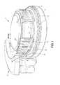
- FIG. 1is a perspective view of a first embodiment of a slide stainer.
- FIG. 2is a top view of a slide frame for providing five sealed cavities above five different slides holding tissue samples.
- FIG. 3is a top view of a slide frame base.
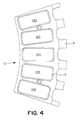
- FIG. 4is a bottom view of a slide frame housing.
- FIG. 5is a top view of the slide frame housing with five microscope slides in their appropriate positions, showing the area to which heat is applied.
- FIG. 6is a cross-sectional view of a slide frame resting on the slide rotor.
- FIG. 7is a schematic diagram of the heater and sensor wiring diagram, on the slide frame, and the interconnection with the temperature controller.
- FIG. 8is a side cross-sectional view of a cartridge pump dispensing mechanism in the liquid dispensing and removal station.
- FIG. 9is a side cross-sectional view of a bulk liquid dispensing station housed in the liquid dispensing and removal station.
- FIGS. 10A and 10Bare side cross sectional views of a vacuum hose and transport mechanism for removing liquid reagent and wash fluids from slides contained on the slide rotor.
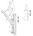
- FIG. 11Ais a side cross-sectional view of the aspiration head, showing its relationship to the glass slide in the slide frame.
- FIG. 11Bis a bottom en face view of the aspiration head.
- FIG. 12is a perspective view of a second embodiment of a slide stainer.
- FIG. 13is a perspective view of the liquid handling zone of the second embodiment of the slide stainer.
- FIGS. 14A and 14Bare side cross-sectional views of the liquid aspiration station of the second embodiment, with the aspiration head in the lowered (FIG. 14A) and raised (FIG. 14B) positions.
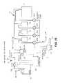
- FIG. 15is a schematic representation of the waste liquid pathways of the second embodiment.
- FIG. 16is a schematic representation of the bulk liquid dispense pathways of the second embodiment.
- FIG. 17is a schematic representation of the individual heaters on the slide rotor and the temperature control boards mounted on the slide rotor.
- FIGS. 18A-Dare a schematic diagram of the electronic circuitry of the temperature control board.
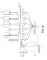
- FIG. 1shows a first embodiment 1 of the invention in perspective view.
- the first embodiment 1comprises a substantially circular assembly base 2 , a slide rotor 3 rotatable on the assembly base 2 , a reagent rotor 4 also rotatable on the assembly base, and a liquid dispensing and removal station 5 .
- the slide rotor 3is driven to rotate by a servo motor (not shown) and carries ten slide frames 6 that are radially asserted into and detachable from it.
- a top view of single slide frame 6is shown in FIG. 2 .
- positions for five slides, each with a tissue sample,are shown in positions 7 a - 7 e .
- the slide frame 6comprises a slide frame base 8 shown in FIG. 3 .
- the slide frame base 8includes a heated area 9 which underlies each of the slide positions 7 a - 7 e and incorporates resistive heating elements, not shown.
- the heating elementsare integrally formed in the slide frame base 8 . Electricity for powering the heating elements is provided into the slide frame 6 from the assembly base 2 via first and second contacts 10 .
- third and fourth contacts 11enable temperature sensing of the heated areas via thermocouples also integrally formed in the slide frame base 8 .
- a sum of three connectorsare required, since contacts 10 and 11 share the same ground connection. Therefore, one of the connectors 11 are left unused.
- FIG. 4is a top view of the slide frame housing 12 showing essentially a rigid plastic or metal frame 13 with five oval holes 14 a - 14 e corresponding to each of the slide positions 7 a - 7 e .
- a silicon rubber gasket 15is also provided under the frame 13 .
- the slide frame housing 12including the gasket 15 and frame 13 , is bolted onto the slide frame base 8 by two Allen bolts 16 to provide individual sealed cavities approximately 0.2-0.4 inches deep over each tissue sample slide placed at each of the slide positions 7 a - 7 e .
- a total of 3 ml of reagents and/or rinsescan be placed in contact with the tissue samples of each one of the slides but a maximum quantity of 2 ml is preferable. Since the silicon gasket 15 is compressed by the frame 13 against the microscope slides (not shown), the cavities over each of the frame positions are mutually sealed from each other.
- FIG. 5is a top view of a slide frame base 8 with five microscope slides 17 in the positions denoted by 7 a - 7 e in FIG. 3 .
- the area of each slide 17 forming cavities, that are delimited by the silicone rubber gasket 15 and holes 14 a - 14 eis indicated by an approximately rectangular line 18 , marking the chamber wall.
- the area denoted by the hatched barsindicates the area of the slide frame base 8 that includes heating elements 9 .
- the entire heated area (hatched bars)is raised to the same temperature, bringing the group of five slides to the same desired temperature.
- the portion of each slide 17 that is not above the heated areadoes not generally bear a biologic tissue specimen. Rather, it is used for labeling purposes.
- FIG. 6is a cross-sectional view of an assembled slide frame base 8 and housing 12 , collectively referred to previously as the slide frame 6 .
- the microscope slide 17is shown held in position, between the slide frame base 8 and housing 12 .
- the slide frame 6is resting on the slide rotor 3 .
- the electrical connection between the slide frame 6 and an edge connector 19is demonstrated.
- Four edge connectors per slide frame 6are provided (contacts 10 and 11 in FIGS. 2 and 3 ).
- the electrical connectionis fed from the edge connector 19 through the slide rotor via an insulated feed-through 20 , to a terminal underneath the slide rotor 3 .
- a wirethen connects the terminal to a source of power or control circuitry (not shown).
- FIG. 7is a schematic diagram, showing two out of the ten heater 91 and sensor 92 circuits that can be placed on the instrument slide rotor.
- the heateris represented schematically as a resistive element, and corresponds to the heated area (hatched bars) of FIG. 5 .
- Contacts 10 and 11share a common ground connection, leaving one of the four connectors unused.
- Each of the circuitsfeeds into a temperature controller, represented schematically 21 .
- Each slide framesends three wires to the temperature controller 21 —a heater power conductor 22 , a sensor conductor 23 , and a ground connection 24 .
- the temperature controller 21is mounted in a stationary position on the assembly base 2 .
- the heaters and sensorsare in frequent motion, they connect to the stationary temperature controller 21 via a service loop (not shown).
- the service loopcontains the wires from each of the edge connectors 19 . Sufficient extra length is provided in the wires so that as the slide rotor rotates, the service loop travels around the slide rotor axis. The slide rotor 3 does not turn more than one full revolution in either direction.
- the wires in the service loopare preferably bundled together with a wire tie, so that individual wires do not become entangled or caught underneath the slide rotor 3 . Since there are three wires per circuit (wires 22 - 24 ), and there are ten slide frames 6 on the slide rotor 3 , the service loop contains a minimum of thirty wires.
- the reagent rotor 4positioned above the slide rotor 3 is the reagent rotor 4 .
- This reagent rotoris similarly adapted to rotate on the assembly base 2 and is driven by another servo motor (not shown) under computer control (not shown).
- the reagent rotor 4 and the slide rotor 3rotate independently of each other.
- the reagent rotor 4is adapted to carry up to ten cartridge frames 25 .
- Each of these cartridge frames 25are detachable from the reagent rotor 4 and can be selectively attached at any one of ten possible points of connection.
- Each cartridge frame 25is capable of carrying five of the cartridge pumps 46 .
- the dispensing station 5comprises a soft hammer 26 for engaging a portion of the cartridge pumps 46 .
- the cartridge pumps 46are constructed so as to dispense liquid when a portion of the cartridge pump 46 , called the metering chamber 42 of the cartridge pump 46 is compressed. It is possible to dispense from any of a plurality of cartridge pumps by rotating the reagent rotor so as to align a desired cartridge pump 46 with the hammer 26 . This provides the capability of dispensing precisely measured amounts of reagent to any slide positioned underneath the cartridge pump 46 adjacent to actuator 26 .
- the mechanism for dispensing from the cartridge pumps 46is shown in greater detail in FIG. 8 .
- the hammer 26is driven by a solenoid or linear stepping motor 43 that is mounted on a front wall 44 , attached to the assembly base 2 .
- a solenoid or linear stepping motor 43that is mounted on a front wall 44 , attached to the assembly base 2 .
- the hammeris shown compressing the metering chamber 42 portion of the cartridge pump. It is important to be able to adjust the speed of compression by the hammer 26 upon the metering chamber 42 . Otherwise, too rapid a compression will cause an excessively forceful ejection of reagent from metering chamber 42 , potentially damaging the tissue section underneath. Therefore, a linear stepping motor is preferred instead of a solenoid .
- the reciprocating hammer of the dispensing actuatorcould take the form of a cam, driven by a rotary motor, that engages the metering chamber 42 so that the rotation of the cam will compress the metering chamber.
- the cartridge pump 46is comprised of a liquid reservoir 45 and the metering chamber 42 .
- the liquid reservoir 45 shown in this first embodiment 1is a syringe barrel.
- the metering chamber 42is comprised of a compressible elastomeric housing with a one-way inlet valve (not shown) and a one-way outlet valve (not shown), both valves aligned in a downwards direction of fluid flow.
- the dispensing station 5further includes a means to dispense liquids from a large bottle (FIG. 9 ).
- Bulk liquid bottles 27that can supply liquid into any one of the microscope slides 17 on any one of the slide frames 6 via rinse tubes 28 .
- Each bulk liquid bottle 27is connected to its own rinse tube 28 .
- the bulk liquid bottles 27are pressurized by a pump (not shown).
- the outflow tube (not shown) from each bulk liquid bottle 27passes through a valve 47 that regulates the flow of liquid from that bottle. By opening the valve for a defined period of time, under computer control (not shown), with a defined pressure within the bottle 27 , a known quantity of liquid can be dispensed onto the slide 17 .
- the liquids placed within the bottles 27are those that are used repeatedly among many different procedures, such as water, saline, and alcohol.
- the bulk liquid bottles 27are screwed into a female threaded cap 48 secured to the underside of the horizontal top wall 49 of the station frame.
- Compressed air from a compressor(not shown) is provided to each bulk liquid bottle 27 through a pressure regulator 50 .
- Tubing from the pressure regulator 51transmits the compressed air to the inlet of the bulk liquid bottle 27 .
- the pressure above the liquidenables the liquid to forced up through the dip tube 52 through the rinse hose 53 when a pinch valve 47 is opened. Depending on the length of time that the pinch valve is opened, a pre-determined amount of liquid can be dispensed through the rinse tube 28 .
- the liquid dispensing and removal assembly 5further includes a liquid removal vacuum station, positioned adjacent to the rinse tubes 28 (not visible in FIG. 1 ).
- a liquid removal vacuum stationpositioned adjacent to the rinse tubes 28 (not visible in FIG. 1 ).
- the reagent rotorpositions the slide at the liquid removal vacuum station, shown in a side cross-sectional representation in FIGS. 10A and 10B.
- An external source of vacuum(not shown) is channeled through a trap flask 29 , ultimately leading to a vacuum hose 30 that terminates in an aspiration head 31 .
- the tubing connectionsare not shown in FIGS. 10A and 10B.
- the vacuum hose 30 and aspiration head 31are supported by a hose transport mechanism 54 that allows the aspiration head 31 to be extended down into a cavity of a slide frame 6 to remove liquid covering the tissue sample on the slide 17 . As the aspiration head contacts the liquid, the liquid is sucked upwards into the tubing and collected into the trap flask 29 .
- the vacuum hose transport mechanism 54comprises a motor 32 .
- a reciprocating link 33is attached to a crank arm 34 so that the rotation of the motor 32 causes the reciprocating link 33 to traverse in a vertical direction.
- a bottom portion of the reciprocating link 33is connected to a lever 55 that is pivotally attached to the station frame.
- the other end of this leveris connected to a vacuum hose clamp 35 that is connected via pivot arms 36 to a plate 37 rigidly attached to the station frame.
- the net effect of these connectionsis that when the motor 32 is rotated, the slide arm 33 descends in a vertical direction.
- the lever 55is pivoted clockwise around its fulcrum causing the hose clamp 35 to pivot up and away on the two pivot arms 36 from the slide as shown in FIG. 10 B.
- the motoris automatically turned off as the link 33 reaches its two extreme ends of movement by the contact of the electrical terminals 39 of the link to the contact plates 38 connected to the station frame.
- FIG. 11Ashows the aspiration head in a lowered position, in cross-section, within the cavity formed by the slide frame 6 .
- the aspiration head 31comprises a hollow interior manifold 40 through which the vacuum force is transmitted across the entire lower surface of the aspiration head 31 .
- Eight holes 41are drilled on the lower face of the aspiration head 31 , through which the suction force is transmitted. Since the microscope slide 17 is planar, liquid on the slide surface spreads out in two dimensions. Therefore, in order to thoroughly remove liquid from all portions of the microscope slide 17 , multiple aspiration sites are needed. We accomplish this with an aspiration head with a planar lower surface with multiple holes.
- the planar surface of the aspiration head 31comes into close parallel apposition to the microscope slide 17 .
- the aspiration headonly contacts the liquid, not the microscope slide itself, lest it damage the glass slide 17 or the biologic specimen that it carries (not shown). Without such a design and only a single aspiration site, such as from a pipette, liquid distant from the aspirator would not be removed. Rather, it would cling to the distant surfaces of the glass slide 17 , because of the surface tension on the glass. This would result in a residual volume of liquid that would otherwise be left on the surface of the slide 17 . Having a close parallel apposition of the aspiration head is also helpful from the perspective of decreasing surface tension during liquid aspiration.
- the close parallel apposition of the bottom surface of the aspiration head with the microscope slide 17creates a type of capillary gap. This gap helps to overcome surface tension, ensuring complete liquid removal.
- a computercontrols the instrument functions. That is, an operator programs the computer with the information such as the location of reagents on the reagent rotor and the location of slides on the slide rotor. The operator then programs the particular histochemical protocol to be performed on the tissue samples. Variables in these protocols can include the particular reagent used on the tissue sample, the time that the tissue sample is allowed to react with the reagent, whether the tissue sample is then heated, the rinse that is then used to wash the reagent away, followed by the subsequent removal of the rinse and reagent to allow subsequent exposure to a possibly different reagent.
- the instrumentenables complete random access, i.e., any reagent to any slide in any sequence.
- FIG. 12A second, preferred, embodiment of the invention is shown in FIG. 12 . Like the previous embodiment, it also comprises two independent carousels that rotate on an assembly base 56 . Bulk liquid bottles 57 are mounted on a bridge 58 that extends across the width of the entire machine, above the reagent rotor. A separate group of trap bottles 59 , for collecting waste liquid, are mounted on the side of the bridge 58 in a compartmentalized shelf. The tubing connections and valves for the bulk liquid bottles 57 and the trap bottles 59 are hidden from view by an upper panel 60 . The front and sides of this embodiment are surrounded by a plexiglass case 61 , that can be manually slid sideways in order to insert cartridge pumps 62 or slides (not shown).
- Slidesare individually inserted and removed via a centrally located slide access door 63 .
- the slides(not shown) are hidden from view by a circular platen 64 that is located above the slides and reagent rotor (not shown).
- Functions similar to the dispensing assembly ( 5 of FIG. 1) in the previous embodimentare accomplished in a somewhat similar liquid handling assembly (not shown) that is positioned in a liquid handling zone 65 .
- FIG. 13shows the individual mechanisms contained within the liquid handling zone 65 , including a hammer 66 for dispensing from cartridge pumps (not shown), an aspiration head 67 for removing liquid from the surface of slides, a bulk liquid dispensing port 68 , and an air-mix head 69 for spreading and mixing liquids on the surface of a slide.
- the electromechanical mechanism for dispensing from cartridge pumps, by compressing a hammer 66 upon a metering chamber of a cartridge pump (not shown in FIG. 13 ),is similar to the previous embodiment (FIG. 8 ). Reagent dispensed from the cartridge pump (not shown) flows onto the slide by passing through a roughly rectangular hole in the platen 64 .
- the aspiration head 67also functions in a similar manner to that of the previous embodiment. In order to simplify the linkage mechanism for lowering and raising the head 67 , the head moves solely in a vertical direction. This is shown in further detail in FIGS. 14A and 14B.
- FIG. 14Ashows a side cross-sectional view of the aspiration head in a down position, within a cavity formed by the microscope slide 75 (bottom surface) and a slide chamber clip 76 (lateral walls). As in the first embodiment, a gasket (not shown) seals the surface where the slide chamber clip 76 contacts the microscope slide 75 .
- a linear stepper motor 73moves the aspiration head up and down, under computer control (demonstrated schematically in FIG. 15 ).
- the aspiration head 67comprises a hollow manifold 74 connected to a source of vacuum. Eight holes communicate between the bottom of the aspiration head 67 and the exterior, through which liquid is aspirated.
- vacuumis supplied to the aspiration head 67 , and the head 67 is lowered adjacent to the slide, the liquid reagent on top of the slide is aspirated off and collected in a trap bottle 59 (shown schematically in FIG. 15 ).
- the aspiration head 67is not in use, it is raised to the up position (FIG. 14 B), allowing free rotation of the slide rotor 77 .
- FIGS. 14A and 14Balso show the physical location of a heating element 78 , represented as a resistive element inside a rectangular box with cross-hatched lines. Each slide rests directly on the heating element 78 , so that heat is directly communicated to the microscope slide. A thermistor is incorporated into each heating element (not shown in FIGS. 14 A and 14 B). Each of forty-nine microscope slides 75 has its own heating element 78 , so that the temperature of each slide 75 can be independently regulated. Power for the heating element 78 is supplied directly from a temperature control board 79 that is affixed to the underside of the slide rotor 77 . Seven identical temperature control boards 79 are so mounted underneath the slide rotor 77 , evenly spaced around the periphery. Each temperature control board supplies power for seven heating elements 78 . The means by which this is accomplished is explained later, in reference to FIGS. 17 and 18 A-D.
- FIG. 15An important aspect of this embodiment, not highlighted in the previous embodiment 1, is the provision for the segregation of waste liquids that are removed from the surface of the slide.
- FIG. 15A schematic diagram explaining how this is accomplished is shown in FIG. 15 .
- Three different waste bottles 59are mounted on the instrument.
- Connections 70are also provided on the instrument for a large external trap bottle 71 , typically of a ten or twenty liter capacity for aqueous waste.
- Four solenoid valves, labelled 80 A- 80 Dcontrol to which bottle aspirated liquid will be directed. These valves are under computer control, schematically represented by the box labelled “controller” 86 .
- Valve 81is a three way valve.
- Valves 80 B- 80 Dfunction similarly for their respective trap bottles 59 .
- a small overflow trap bottle 83is also inserted into the line with its own fluid sensor 93 .
- the liquid handling zonealso includes an air-mix head 69 .
- a schematic representation of the air flow into the air-mix head 69is shown in FIG. 15 .
- the pumpgenerates a high velocity air stream that is channeled into the air-mix head 69 .
- Air intake to the pumpis via the three way solenoid valve 81 (FIG. 15 ).
- the solenoid valve 81(FIG. 15) switches so as to channel air directly from the atmosphere to the pump (FIG. 15 ), bypassing the aspiration system and trap bottles 59 and 71 .
- the high velocity air flowis focused onto the slide.
- the air-mix head 69travels back and forth along the length of the slide, pushed and pulled by a belt and pulley that is attached to a motor (not shown).
- the net effect of this systemis to direct a curtain of air back and forth along the length of the slide, causing liquid to be mixed and spread along the surface of the microscope slide.
- the liquid handling zone 65includes a bulk liquid dispensing port 68 (FIG. 13 ).
- the function of the rinse tubes 28 of the first embodiment 1 (shown in FIG. 1)are all incorporated into a single bulk liquid dispensing port 68 in this preferred embodiment. Therefore, slides are positioned under the bulk liquid dispensing port 68 regardless of the bulk liquid bottle that the liquid is actually derived from.
- a schematic representation of the fluid pathways and control valvesis shown in FIG. 16 .
- the bulk liquid bottles 57are each connected to a source of pressure, that is generated by a pump 85 .
- the pressureis communicated to the bulk liquid bottles 57 via a pressure manifold 94 .
- Solenoid valves 72 a - 72 fare placed between the bulk liquid dispensing port 68 and each bulk liquid bottle 57 . Liquid flows out the bulk liquid dispensing port 68 only when one or more of the valves 72 a - 72 f are open.
- a pressure switch 84also communicates with the pressure manifold 94 . It is capable of sensing the amount or pressure contained within the manifold 94 . When it falls below a specified level, it communicates with the controller 86 causing activation of the pump 85 . As the pump generates an increased amount of air pressure within the pressure manifold, the pressure switch resets, causing the pump to stop pumping. In this manner, a relatively constant pressure head is maintained within the pressure manifold 94 .
- a dispense sensor 95is positioned underneath the bulk liquid dispensing port 68 to provide verification that liquid was dispensed when one of the solenoid valves 72 a - 72 f were transiently opened.
- the dispense sensor 95comprises an optical sensor and an LED light source. When liquid is dispensed from the bulk liquid dispensing port 68 , the liquid interrupts the light beam. The change in resistance across the sensor as a result of the decrement in light intensity is communicated to the controller 86 .
- This second, preferred embodiment of the inventionincludes the capability to independently heat the forty-nine slides to different temperatures.
- a novel aspect of this embodimentis the method for independently regulating the amount of power that each of the forty-nine heaters receives.
- each heateralso incorporates a temperature sensor. Each of these sensors must communicate with the computer 86 in order to allow for appropriate temperature feedback and regulation.
- groups of up to five slideswere under a single, common temperature control mechanism.
- Each heating grouphad wires that directly connected with the temperature controller (FIG. 7 ). With three wires per group (power for heat, sensor feedback, and a shared ground) and ten groups of slides, at least thirty wires were contained in the service loop. If a similar system were used for forty-nine different heaters, as in this preferred embodiment, 147 wires would be required in the service loop. Such a bulky service loop would be problematic. Therefore, an alternative method is developed in this preferred embodiment.
- FIG. 17shows the relationship between each of the heating elements 78 mounted on the slide rotor 77 , depicting the heating element 78 as a resistive element.
- a single sensor 87is adjacent to each heater.
- the combination of a single heating element 78 and sensor 87are so positioned so as to provide a location 88 for a single slide to be heated.
- the physical layout of this location 88is demonstrated in FIGS. 14A and 14B.
- Two wire leads from each heating element 78 , and two wire leads from each sensor 87are connected directly to a temperature control board mounted on the slide rotor 77 .
- Each temperature control boardis capable of connecting to up to eight different heater and sensor pairs.
- this embodimentincorporates forty-nine slide positions, seven boards 79 are mounted to the underside of the slide rotor, each connecting to seven heater-sensor pairs. One heater-sensor position per temperature controller board 79 is not used. Also shown in FIG. 17 is the serial connection 89 of each of the seven temperature control boards, in a daisy-chain configuration, by six wires.
- the first temperature control boardis connected via a service loop 90 to the computer 86 .
- the service loopcontains only six wires tied together in a harness.
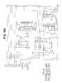
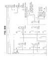
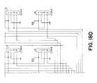
- FIGS. 18A-Dare an electronic schematic diagram of the temperature control board 79 .
- the design of the temperature control board 79was driven by the need to minimize the number of wires in the flexible cable (service loop 90 ) between the heaters and the computer.
- seven temperature controller boards 79are used, each mounted on the slide rotor.
- each heateris positioned close to its associated electronics and the size of each board 79 is kept small because each runs only seven heating elements 78 .
- Each temperature controller board 79includes the function of an encoder and decoder of temperature data. That data relates to the actual and desired temperature of each of heating elements 78 .
- the dataflows back and forth between the computer 86 and the temperature control board 79 .
- the computercommunicates that information to the temperature control board 79 .
- the temperature control board 79directly regulates the amount of power flowing to each heater.
- the temperature control board 79 systemwas designed as a shift register.
- the machine's controlling microprocessorplaces bits of data one at a time on a transmission line, and toggles a clock line for each bit. This causes data to be sent through two shift register chips on each control board, each taking eight bits. There are thus 16 ⁇ 7 or 112 bits to be sent out.
- the datacomes in on connector J 9 . 1
- the clock lineis J 9 . 2 .
- the shift registers used in this designare “double buffered,” which means that the output data will not change until there is a transition on a second clock (R clock), which comes in on pin J 9 . 3 .
- the two clocksare sent to all seven boards in parallel, while the data passes through the shift register chips (U 1 and U 2 ) on each board and is sent on from the second shift register's “serial out” pin SDOUT to the input pin of the next board in daisy chain fashion.
- a matching connector, J 10is wired in parallel with J 9 with the exception of pin 1 .
- J 10is the “output” connector, which attaches via a short cable to J 9 of the next board in line, for a total of seven boards.
- the other three pins of J 9are used for power to run the electronics (J 9 . 4 ), electronic ground (J 9 . 5 ), and a common return line (J 9 . 6 ) for temperature measurement function from the sensors.
- Component U 4is an analog multiplexer which performs this function. Of the four digital bits which are received serially, one is used to enable U 4 , and the other three are used to select one of the component's eight channels (of which only seven are used). If pin four is driven low, U 4 for that board 79 becomes active and places the voltage from one of the seven channels of that board on the shared output line at J 9 . 6 . Conversely, if pin four is pulled high, U 4 's output remains in a high impedance state and the output line is not driven. This allows data from a selected board 79 to be read, with the remaining boards 79 having no effect on the signal. Multiplexer U 4 can only be enabled on one board 79 at a time; if more than one were turned on at a time, the signals would conflict and no useful data would be transmitted.
- Temperature sensingis accomplished by a voltage divider technique.
- a thermistor 87 and a fixed resistor(5.6 kilohms, R 1 -R 8 , contained in RS 1 ) are placed in series across the 5 volt electronic power supply. When the thermistor is heated, its resistance drops and the voltage at the junction point with the 5.6 kilohm resistor will drop.
- the temperature control boards 79are small and inexpensive. Moreover, the heater boards are all identical. No “address” needs to be set for each board 79 . Lastly, the service loop 90 is small in size.
- each temperature control board 79could be set up with a permanent “address” formed by adding jumper wires or traces cut on the board.
- the processorwould send out a packet of data which would contain an address segment and a data segment, and the data would be loaded to the board whose address matched the address sent out.
- This approachtakes less time to send data to a particular board, but the address comparison takes extra hardware. It also demands extra service loop wires to carry the data (if sent in parallel) or an extra shift register chip if the address is sent serially.
- each temperature control board 79could have its own microprocessor. They could all be connected via a serial data link to the main computer 86 . This approach uses even fewer connecting wires than the present embodiment, but the cost of hardware is high. It also still implies an addressing scheme, meaning that the boards would not be identical. Also, code for the microprocessors would be required.
Landscapes
- Health & Medical Sciences (AREA)
- Chemical & Material Sciences (AREA)
- Life Sciences & Earth Sciences (AREA)
- Biochemistry (AREA)
- General Health & Medical Sciences (AREA)
- Physics & Mathematics (AREA)
- Analytical Chemistry (AREA)
- General Physics & Mathematics (AREA)
- Immunology (AREA)
- Pathology (AREA)
- Chemical Kinetics & Catalysis (AREA)
- Molecular Biology (AREA)
- Clinical Laboratory Science (AREA)
- Engineering & Computer Science (AREA)
- Biomedical Technology (AREA)
- Sampling And Sample Adjustment (AREA)
- Automatic Analysis And Handling Materials Therefor (AREA)
- Devices For Use In Laboratory Experiments (AREA)
- Yarns And Mechanical Finishing Of Yarns Or Ropes (AREA)
- Control Of Resistance Heating (AREA)
- Electric Stoves And Ranges (AREA)
- Thermotherapy And Cooling Therapy Devices (AREA)
- Chair Legs, Seat Parts, And Backrests (AREA)
- Investigating Or Analysing Biological Materials (AREA)
Abstract
Description
Claims (7)
Priority Applications (4)
| Application Number | Priority Date | Filing Date | Title |
|---|---|---|---|
| US09/688,619US6541261B1 (en) | 1998-02-27 | 2000-10-16 | Method using a slide stainer with independent slide heating regulation |
| US10/027,746US6783733B2 (en) | 1998-02-27 | 2001-12-20 | Random access slide stainer with independent slide heating regulation |
| US10/864,620US7217392B2 (en) | 1998-02-27 | 2004-06-09 | Random access slide stainer with independent slide heating regulation |
| US11/803,545US7553672B2 (en) | 1998-02-27 | 2007-05-14 | Random access slide stainer with independent slide heating regulation |
Applications Claiming Priority (2)
| Application Number | Priority Date | Filing Date | Title |
|---|---|---|---|
| US09/032,676US6183693B1 (en) | 1998-02-27 | 1998-02-27 | Random access slide stainer with independent slide heating regulation |
| US09/688,619US6541261B1 (en) | 1998-02-27 | 2000-10-16 | Method using a slide stainer with independent slide heating regulation |
Related Parent Applications (1)
| Application Number | Title | Priority Date | Filing Date |
|---|---|---|---|
| US09/032,676DivisionUS6183693B1 (en) | 1998-02-27 | 1998-02-27 | Random access slide stainer with independent slide heating regulation |
Related Child Applications (1)
| Application Number | Title | Priority Date | Filing Date |
|---|---|---|---|
| US10/027,746ContinuationUS6783733B2 (en) | 1998-02-27 | 2001-12-20 | Random access slide stainer with independent slide heating regulation |
Publications (1)
| Publication Number | Publication Date |
|---|---|
| US6541261B1true US6541261B1 (en) | 2003-04-01 |
Family
ID=21866219
Family Applications (5)
| Application Number | Title | Priority Date | Filing Date |
|---|---|---|---|
| US09/032,676Expired - LifetimeUS6183693B1 (en) | 1998-02-27 | 1998-02-27 | Random access slide stainer with independent slide heating regulation |
| US09/688,619Expired - LifetimeUS6541261B1 (en) | 1998-02-27 | 2000-10-16 | Method using a slide stainer with independent slide heating regulation |
| US10/027,746Expired - LifetimeUS6783733B2 (en) | 1998-02-27 | 2001-12-20 | Random access slide stainer with independent slide heating regulation |
| US10/864,620Expired - Fee RelatedUS7217392B2 (en) | 1998-02-27 | 2004-06-09 | Random access slide stainer with independent slide heating regulation |
| US11/803,545Expired - Fee RelatedUS7553672B2 (en) | 1998-02-27 | 2007-05-14 | Random access slide stainer with independent slide heating regulation |
Family Applications Before (1)
| Application Number | Title | Priority Date | Filing Date |
|---|---|---|---|
| US09/032,676Expired - LifetimeUS6183693B1 (en) | 1998-02-27 | 1998-02-27 | Random access slide stainer with independent slide heating regulation |
Family Applications After (3)
| Application Number | Title | Priority Date | Filing Date |
|---|---|---|---|
| US10/027,746Expired - LifetimeUS6783733B2 (en) | 1998-02-27 | 2001-12-20 | Random access slide stainer with independent slide heating regulation |
| US10/864,620Expired - Fee RelatedUS7217392B2 (en) | 1998-02-27 | 2004-06-09 | Random access slide stainer with independent slide heating regulation |
| US11/803,545Expired - Fee RelatedUS7553672B2 (en) | 1998-02-27 | 2007-05-14 | Random access slide stainer with independent slide heating regulation |
Country Status (8)
| Country | Link |
|---|---|
| US (5) | US6183693B1 (en) |
| EP (3) | EP1600759A3 (en) |
| JP (1) | JP4269030B2 (en) |
| AT (1) | ATE304168T1 (en) |
| AU (1) | AU2878799A (en) |
| CA (1) | CA2321823C (en) |
| DE (1) | DE69927137T2 (en) |
| WO (1) | WO1999044032A1 (en) |
Cited By (41)
| Publication number | Priority date | Publication date | Assignee | Title |
|---|---|---|---|---|
| US20020160370A1 (en)* | 2001-04-30 | 2002-10-31 | Bass Jay K. | Error detection in chemical array fabrication |
| US20030017075A1 (en)* | 1999-07-08 | 2003-01-23 | Lee Angros | In situ heat induced antigen recovery and staining method |
| US20030087444A1 (en)* | 2001-11-05 | 2003-05-08 | Industrial Technology Research Institute | Method and apparatus for manufacturing biochip |
| US20030203493A1 (en)* | 2002-04-26 | 2003-10-30 | Ventana Medical Systems, Inc. | Automated molecular pathology apparatus having fixed slide platforms |
| US20030211630A1 (en)* | 1998-02-27 | 2003-11-13 | Ventana Medical Systems, Inc. | Automated molecular pathology apparatus having independent slide heaters |
| US20040052685A1 (en)* | 1998-02-27 | 2004-03-18 | Ventana Medical Systems, Inc. | Automated molecular pathology apparatus having independent slide heaters |
| US20040191128A1 (en)* | 1992-05-11 | 2004-09-30 | Cytologix Corporation | Slide stainer with heating |
| US20040221477A1 (en)* | 2002-09-12 | 2004-11-11 | Lg Electronics Inc. | Structure of motor shaft in clothes dryer |
| US20040241050A1 (en)* | 1998-02-27 | 2004-12-02 | Cytologix Corporation | Random access slide stainer with independent slide heating regulation |
| US20040266015A1 (en)* | 2002-12-20 | 2004-12-30 | Dakocytomation Denmark A/S | Automated sample processing apparatus and a method of automated treating of samples and use of such apparatus |
| US20050022731A1 (en)* | 2003-07-30 | 2005-02-03 | Bernard Petrillo | Immersion optics fluid dispenser |
| US20050035156A1 (en)* | 2003-08-11 | 2005-02-17 | Michael Hersch | Fluid dispensing apparatus |
| US20060093520A1 (en)* | 2001-11-02 | 2006-05-04 | Lemme Charles D | Automated molecular pathology apparatus having fixed slide platforms |
| US20060153736A1 (en)* | 2003-09-09 | 2006-07-13 | Kalra Krishan L | Sample processing system |
| US20060171857A1 (en)* | 2003-08-11 | 2006-08-03 | Stead Ronald H | Reagent container and slide reaction and retaining tray, and method of operation |
| US20060173575A1 (en)* | 2003-08-11 | 2006-08-03 | Gilles Lefebvre | Automated reagent dispensing system and method of operation |
| US20060169719A1 (en)* | 2003-08-11 | 2006-08-03 | Bui Xuan S | Manifold assembly |
| US20060275889A1 (en)* | 1999-07-08 | 2006-12-07 | Lee Angros | In situ heat induced antigen recovery and staining apparatus and method |
| US20060281116A1 (en)* | 1999-07-08 | 2006-12-14 | Lee Angros | In situ heat induced antigen recovery and staining apparatus and method |
| US20070092431A1 (en)* | 2005-06-28 | 2007-04-26 | Resasco Daniel E | Methods for growing and harvesting carbon nanotubes |
| US20070272710A1 (en)* | 2006-05-25 | 2007-11-29 | Sakura Finetek, U.S.A., Inc. | Fluid dispensing apparatus |
| US20080089808A1 (en)* | 2006-10-17 | 2008-04-17 | Preyas Sarabhai Shah | Slide stainer with multiple heater stations |
| US20080194034A1 (en)* | 2005-04-21 | 2008-08-14 | Celerus Diagnostics, Inc. | Method And Apparatus For Automated Rapid Immunohistochemistry |
| US7425306B1 (en) | 2001-09-11 | 2008-09-16 | Ventana Medical Systems, Inc. | Slide heater |
| US20080318129A1 (en)* | 2005-01-25 | 2008-12-25 | Gene Lewis | Fuel Cell Cathodes |
| US20090017491A1 (en)* | 2007-07-10 | 2009-01-15 | Ventana Medical Systems, Inc. | Apparatus and method for biological sample processing |
| US20090253592A1 (en)* | 2003-12-23 | 2009-10-08 | Kram Brian H | Method and apparatus for treating a biological sample with a liquid reagent |
| WO2009152056A1 (en)* | 2008-06-09 | 2009-12-17 | Pacific Bioscience Laboratories, Inc. | Sonic applicator for skin formulations |
| US20100068757A1 (en)* | 2008-08-29 | 2010-03-18 | Angros Lee H | In situ heat induced antigen recovery and staining apparatus and method |
| US7718435B1 (en) | 1992-05-11 | 2010-05-18 | Dako Denmark A/S | Automated slide stainer with slide housing |
| US20100144018A1 (en)* | 2008-12-10 | 2010-06-10 | Rushabh Instruments, Llc | Automated slide staining apparatus |
| US20100209298A1 (en)* | 2006-03-09 | 2010-08-19 | Kalra Krishan L | Sample Processing System |
| US7951612B2 (en) | 1999-07-08 | 2011-05-31 | Lee H. Angros | In situ heat induced antigen recovery and staining apparatus and method |
| US20110150725A1 (en)* | 2005-05-24 | 2011-06-23 | Lee Angros | In situ heat induced antigen recovery and staining apparatus and method |
| US8501434B2 (en) | 2010-10-06 | 2013-08-06 | Biocare, LLC | Method for processing non-liquid biological samples with dynamic application of a processing liquid |
| US8580568B2 (en) | 2011-09-21 | 2013-11-12 | Sakura Finetek U.S.A., Inc. | Traceability for automated staining system |
| US8752732B2 (en) | 2011-02-01 | 2014-06-17 | Sakura Finetek U.S.A., Inc. | Fluid dispensing system |
| US8932543B2 (en) | 2011-09-21 | 2015-01-13 | Sakura Finetek U.S.A., Inc. | Automated staining system and reaction chamber |
| US9945763B1 (en) | 2011-02-18 | 2018-04-17 | Biocare Medical, Llc | Methods and systems for immunohistochemistry heat retrieval of biological samples |
| US10746752B2 (en) | 2009-11-13 | 2020-08-18 | Ventana Medical Systems, Inc. | Opposables and automated specimen processing systems with opposables |
| WO2025065564A1 (en)* | 2023-09-28 | 2025-04-03 | Shenzhen Prs Ltd. | Dynamically controlled immunohistochemistry (ihc) stainer systems and methods |
Families Citing this family (91)
| Publication number | Priority date | Publication date | Assignee | Title |
|---|---|---|---|---|
| US7112449B1 (en)* | 2000-04-05 | 2006-09-26 | Nanogram Corporation | Combinatorial chemical synthesis |
| GB9803684D0 (en)* | 1998-02-24 | 1998-04-15 | Genevac Ltd | Method and apparatus for controlling temperature during evaporation of samples |
| US7396508B1 (en)* | 2000-07-12 | 2008-07-08 | Ventana Medical Systems, Inc. | Automated molecular pathology apparatus having independent slide heaters |
| AU763354B2 (en) | 1998-02-27 | 2003-07-17 | Ventana Medical Systems, Inc. | Automated molecular pathology apparatus having independent slide heaters |
| US6495106B1 (en)* | 1998-03-24 | 2002-12-17 | Biogenex Laboratories | Automated staining apparatus |
| US6403931B1 (en)* | 1999-10-07 | 2002-06-11 | Ventana Medical Systems, Inc. | Slide heater calibrator and temperature converter apparatus and method |
| US6544480B1 (en)* | 1999-10-26 | 2003-04-08 | Tibotec Bvba | Device and related method for dispensing small volumes of liquid |
| US7369304B2 (en)* | 1999-10-29 | 2008-05-06 | Cytyc Corporation | Cytological autofocusing imaging systems and methods |
| DE10006084B4 (en)* | 2000-02-11 | 2009-01-02 | Leica Biosystems Nussloch Gmbh | Stainer with a heating station |
| DE10041227B4 (en)* | 2000-08-22 | 2011-12-29 | Leica Biosystems Nussloch Gmbh | Device for the treatment of objects |
| GB0117706D0 (en)* | 2001-02-16 | 2001-09-12 | Aventis Pharm Prod Inc | Automated semi-solid matrix assay and liquid handler apparatus for the same |
| US6889468B2 (en)* | 2001-12-28 | 2005-05-10 | 3M Innovative Properties Company | Modular systems and methods for using sample processing devices |
| US7410615B2 (en)* | 2002-01-24 | 2008-08-12 | Perkinelmer Las, Inc. | Precision liquid dispensing system |
| US11249095B2 (en) | 2002-04-15 | 2022-02-15 | Ventana Medical Systems, Inc. | Automated high volume slide processing system |
| DK1494808T3 (en)* | 2002-04-15 | 2013-09-23 | Ventana Med Syst Inc | High capacity automated slide staining system |
| US7468161B2 (en) | 2002-04-15 | 2008-12-23 | Ventana Medical Systems, Inc. | Automated high volume slide processing system |
| WO2003106157A2 (en)* | 2002-06-14 | 2003-12-24 | Chromavision Medical Systems, Inc. | Automated slide staining apparatus |
| US6585936B1 (en) | 2002-06-28 | 2003-07-01 | Preyas Sarabhai Shah | Slide stainer with controlled fluid flow |
| US7875245B2 (en)* | 2003-05-14 | 2011-01-25 | Dako Denmark A/S | Method and apparatus for automated pre-treatment and processing of biological samples |
| US6746966B1 (en)* | 2003-01-28 | 2004-06-08 | Taiwan Semiconductor Manufacturing Company | Method to solve alignment mark blinded issues and a technology for application of semiconductor etching at a tiny area |
| DE10325300A1 (en)* | 2003-06-04 | 2005-01-20 | Siemens Ag | thermocycler |
| EP1631388A4 (en)* | 2003-06-09 | 2007-09-05 | Dako Denmark As | Diaphram metering chamber dispensing systems |
| US7273591B2 (en)* | 2003-08-12 | 2007-09-25 | Idexx Laboratories, Inc. | Slide cartridge and reagent test slides for use with a chemical analyzer, and chemical analyzer for same |
| US7517498B2 (en)* | 2003-08-19 | 2009-04-14 | Agilent Technologies, Inc. | Apparatus for substrate handling |
| US7944467B2 (en)* | 2003-12-01 | 2011-05-17 | Omnivision Technologies, Inc. | Task-based imaging systems |
| US7588733B2 (en) | 2003-12-04 | 2009-09-15 | Idexx Laboratories, Inc. | Retaining clip for reagent test slides |
| US7553451B2 (en)* | 2004-09-29 | 2009-06-30 | Cytyc Corporation | Platform apparatus with horizontal slide translation and method |
| TWI249034B (en)* | 2005-01-21 | 2006-02-11 | Tera Automation Corp Ltd | Storage and injection mechanism of synchronous analysis instrument |
| RU2439572C2 (en)* | 2005-05-24 | 2012-01-10 | Ли Х. АНГРОС | APPARATUS FOR CAUSED BY THERMAL PROCESSING RESTORATION OF ANTIGEN in situ AND STAINING AND METHOD |
| US7754474B2 (en)* | 2005-07-05 | 2010-07-13 | 3M Innovative Properties Company | Sample processing device compression systems and methods |
| US7323660B2 (en)* | 2005-07-05 | 2008-01-29 | 3M Innovative Properties Company | Modular sample processing apparatus kits and modules |
| US7763210B2 (en)* | 2005-07-05 | 2010-07-27 | 3M Innovative Properties Company | Compliant microfluidic sample processing disks |
| WO2008008084A2 (en)* | 2005-09-19 | 2008-01-17 | Cdm Optics, Inc. | Task-based imaging systems |
| WO2007059779A2 (en)* | 2005-11-28 | 2007-05-31 | Dako Denmark A/S | Cyanine dyes and methods for detecting a target using said dyes |
| DE102006040670A1 (en)* | 2006-08-30 | 2008-03-20 | Transcoject Gmbh & Co. Kg | Device for removing liquids |
| CN200960457Y (en)* | 2006-10-26 | 2007-10-17 | 深圳迈瑞生物医疗电子股份有限公司 | Solid directly-heated reacting disc structure |
| WO2008140742A1 (en)* | 2007-05-08 | 2008-11-20 | Idexx Laboratories, Inc. | Chemical analyzer |
| CA2742473C (en) | 2008-11-12 | 2015-02-24 | Ventana Medical Systems, Inc. | Methods and apparatuses for heating slides carrying specimens |
| WO2010074917A1 (en)* | 2008-12-24 | 2010-07-01 | Ventana Medical Systems, Inc. | Microscope-slide dryer |
| US20100222937A1 (en)* | 2009-02-27 | 2010-09-02 | Gm Global Technology Operations, Inc. | Heater control system |
| US9528919B2 (en) | 2009-04-27 | 2016-12-27 | Becton, Dickinson And Company | Sample preparation device and associated method |
| USD638951S1 (en) | 2009-11-13 | 2011-05-31 | 3M Innovative Properties Company | Sample processing disk cover |
| USD638550S1 (en) | 2009-11-13 | 2011-05-24 | 3M Innovative Properties Company | Sample processing disk cover |
| US8834792B2 (en) | 2009-11-13 | 2014-09-16 | 3M Innovative Properties Company | Systems for processing sample processing devices |
| USD667561S1 (en) | 2009-11-13 | 2012-09-18 | 3M Innovative Properties Company | Sample processing disk cover |
| US20110117607A1 (en)* | 2009-11-13 | 2011-05-19 | 3M Innovative Properties Company | Annular compression systems and methods for sample processing devices |
| US8765476B2 (en)* | 2009-12-22 | 2014-07-01 | Biocare Medical, Llc | Methods and systems for efficient automatic slide staining in immunohistochemistry sample processing |
| CH703127A1 (en)* | 2010-05-12 | 2011-11-15 | Tecan Trading Ag | Dispenser and method for dispensing flowable or pourable materials. |
| US9200990B2 (en)* | 2010-12-14 | 2015-12-01 | Rushabh Instruments, Llc | Tissue processor |
| CN102175499B (en)* | 2011-01-31 | 2012-09-05 | 浙江世纪康大医疗科技有限公司 | Temperature-controlled heating device for dyeing instrument |
| IT1403834B1 (en)* | 2011-02-03 | 2013-10-31 | Cps Color Equipment Spa | DISPENSE EQUIPMENT FOR FLUID PRODUCTS |
| WO2012117294A2 (en)* | 2011-02-28 | 2012-09-07 | Dako Denmark A/S | Two phase immiscible system for the pretreatment of embedded biological samples |
| KR20140022399A (en) | 2011-05-18 | 2014-02-24 | 쓰리엠 이노베이티브 프로퍼티즈 컴파니 | Systems and methods for volumetric metering on a sample processing device |
| USD672467S1 (en) | 2011-05-18 | 2012-12-11 | 3M Innovative Properties Company | Rotatable sample processing disk |
| WO2012158997A1 (en) | 2011-05-18 | 2012-11-22 | 3M Innovative Properties Company | Systems and methods for detecting the presence of a selected volume of material in a sample processing device |
| CN103501908B (en) | 2011-05-18 | 2016-03-16 | 3M创新有限公司 | Systems and methods for valve tuning on a sample processing device |
| EP2780688B1 (en) | 2011-11-16 | 2022-09-14 | Leica Biosystems Melbourne Pty Ltd | Biological sample treatment apparatus |
| US10041950B2 (en) | 2012-03-27 | 2018-08-07 | Ventana Medical Systems, Inc. | Signaling conjugates and methods of use |
| EP2864754B1 (en) | 2012-06-22 | 2020-08-26 | Leica Biosystems Nussloch GmbH | Tissue sample container |
| WO2013192606A1 (en) | 2012-06-22 | 2013-12-27 | Leica Biosystems Nussloch Gmbh | Biopsy tissue sample transport device and method of using thereof |
| US9989448B2 (en) | 2012-12-26 | 2018-06-05 | Ventana Medical Systems, Inc. | Specimen processing systems and methods for holding slides |
| US11274998B2 (en) | 2012-12-26 | 2022-03-15 | Ventana Medical Systems, Inc. | Specimen processing systems and methods for holding slides |
| EP2938999B1 (en)* | 2012-12-26 | 2017-06-14 | Ventana Medical Systems, Inc. | Specimen processing systems and methods for holding slides |
| CN103149070B (en)* | 2013-03-11 | 2014-10-08 | 黄石市第一医院 | Automatic slide stainer |
| CA2845832C (en) | 2013-03-15 | 2020-09-22 | Leica Biosystems Nussloch Gmbh | Tissue cassette with biasing element |
| US9097629B2 (en) | 2013-03-15 | 2015-08-04 | Leica Biosystems Nussloch Gmbh | Tissue cassette with retractable member |
| US9052256B2 (en) | 2013-03-15 | 2015-06-09 | Leica Biosystems Nussloch Gmbh | Method for processing and embedding tissue |
| PE20150655A1 (en)* | 2013-10-15 | 2015-05-19 | Univ Pontificia Catolica Peru | AUTOMATIC SPUTUM SAMPLE PREPARATION EQUIPMENT |
| CN105793690B (en) | 2013-12-13 | 2020-01-03 | 文塔纳医疗系统公司 | Automated histological processing of biological samples and related techniques |
| US10119889B2 (en) | 2013-12-17 | 2018-11-06 | Aquaro Histology, Inc. | System and method for mounting a specimen on a slide |
| WO2015095403A1 (en) | 2013-12-17 | 2015-06-25 | Alessi Technologies, Inc. | System and method for biological specimen mounting |
| WO2015106008A1 (en) | 2014-01-10 | 2015-07-16 | Idexx Laboratories, Inc. | Chemical analyzer |
| US10634590B2 (en) | 2014-03-11 | 2020-04-28 | Emd Millipore Corporation | IHC, tissue slide fluid exchange disposable and system |
| WO2016170008A1 (en)* | 2015-04-20 | 2016-10-27 | Ventana Medical Systems, Inc. | Inkjet deposition of reagents for histological samples |
| EP3325938B1 (en)* | 2015-05-25 | 2022-05-11 | Natarajan, Adarsh | Sample stainer |
| EP4582813A3 (en) | 2015-06-26 | 2025-08-27 | Abbott Laboratories | Rotating device in a diagnostic analyzer |
| EP3314269A4 (en) | 2015-06-26 | 2019-01-23 | Abbott Laboratories | Reaction vessel exchanger device for a diagnostic analyzer |
| US10021739B2 (en)* | 2015-07-08 | 2018-07-10 | Mks Instruments, Inc. | Trimmable heater |
| KR20170007181A (en) | 2015-07-10 | 2017-01-18 | 3스캔 인크. | Spatial multiplexing of histological stains |
| JP2019512677A (en) | 2016-02-29 | 2019-05-16 | ベンタナ メディカル システムズ, インコーポレイテッド | System and method for dispensing characterization |
| EP3452808A1 (en) | 2016-05-03 | 2019-03-13 | Ventana Medical Systems, Inc. | System and method for monitoring reagent concentrations |
| WO2017218882A1 (en) | 2016-06-16 | 2017-12-21 | Nanocytomics, LLC | Automated staining system |
| CA3055284A1 (en)* | 2017-03-31 | 2018-10-04 | X-Zell Inc. | Automatic slide staining and cooling systems |
| KR102059482B1 (en)* | 2018-09-17 | 2019-12-26 | (의)삼성의료재단 | Tissue sample staining apparatus |
| CN113874115A (en)* | 2019-05-01 | 2021-12-31 | 卢米耐克斯公司 | Apparatus and method for thermally cycling a sample |
| CN211235173U (en)* | 2019-11-26 | 2020-08-11 | 莱卡生物系统努斯洛赫有限责任公司 | Tissue treatment equipment |
| CN113495028A (en)* | 2020-03-18 | 2021-10-12 | 苏州百源基因技术有限公司 | High-efficient automatic dyeing appearance |
| CA3185353A1 (en) | 2020-07-10 | 2022-01-13 | Jonathan W. LAWRENCE | Point-of-care medical diagnostic analyzer and devices, systems, and methods for medical diagnostic analysis of samples |
| CN112763294B (en)* | 2020-12-29 | 2023-09-08 | 广东金泉医疗科技有限公司 | Heat treatment module and automatic drop dyeing sealing piece equipment with same |
| WO2023159391A1 (en)* | 2022-02-23 | 2023-08-31 | Leica Biosystems Nussloch Gmbh | System for microtomy laboratory with single controller |
| CN120380313A (en)* | 2022-12-23 | 2025-07-25 | 株式会社日立高新技术 | Slide glass cooling/heating device and slide glass cooling/heating method |
Citations (37)
| Publication number | Priority date | Publication date | Assignee | Title |
|---|---|---|---|---|
| US3853092A (en) | 1973-10-25 | 1974-12-10 | Corning Glass Works | Apparatus for nutating and staining a microscope slide |
| US3979576A (en) | 1973-06-14 | 1976-09-07 | Janson Sven Olof | Electric heating element control circuit |
| US4043292A (en) | 1975-07-21 | 1977-08-23 | Corning Glass Works | Microscope slide staining apparatus having temperature control |
| US4092952A (en) | 1977-08-19 | 1978-06-06 | Wilkie Ronald N | Automatic slide stainer |
| US4296069A (en)* | 1980-06-16 | 1981-10-20 | Eastman Kodak Company | Apparatus for processing an analysis slide |
| US4358470A (en) | 1978-02-10 | 1982-11-09 | Lkb-Produkter Ab | Process and apparatus for the treatment of samples with a succession of liquids |
| US4384193A (en) | 1981-06-09 | 1983-05-17 | Immulok, Inc. | Incubating device for specimen mounted on glass slides in immunoassays |
| US4430299A (en)* | 1981-06-18 | 1984-02-07 | Coulter Electronics, Inc. | Apparatus for monitoring chemical reactions |
| US4543236A (en) | 1979-04-14 | 1985-09-24 | Gise Hardo F Von | Incubating apparatus for selective and exact treatment of histological preparations |
| EP0201780A1 (en) | 1985-04-27 | 1986-11-20 | Jan Hastka | Apparatus and method for cytological and histological examinations of sample slides |
| US4629862A (en) | 1984-03-28 | 1986-12-16 | Olympus Optical Company Ltd. | Sample heater for use in microscopes |
| US4731335A (en) | 1985-09-13 | 1988-03-15 | Fisher Scientific Company | Method for treating thin samples on a surface employing capillary flow |
| US4847208A (en) | 1987-07-29 | 1989-07-11 | Bogen Steven A | Apparatus for immunohistochemical staining and method of rinsing a plurality of slides |
| US4858155A (en) | 1985-12-24 | 1989-08-15 | Beckman Instruments, Inc. | Reaction temperature control system |
| US4865986A (en) | 1988-10-06 | 1989-09-12 | Coy Corporation | Temperature control apparatus |
| US4933146A (en) | 1986-07-11 | 1990-06-12 | Beckman Instruments, Inc. | Temperature control apparatus for automated clinical analyzer |
| US4985206A (en) | 1987-09-30 | 1991-01-15 | Shandon Scientific Limited | Tissue processing apparatus |
| US5075079A (en) | 1990-05-21 | 1991-12-24 | Technicon Instruments Corporation | Slide analysis system |
| US5105066A (en) | 1988-12-30 | 1992-04-14 | Philippe Houdy | Device comprising a heating sample carrier |
| US5154889A (en) | 1986-08-07 | 1992-10-13 | Fuji Photo Film Co., Ltd. | Chemical analysis apparatus |
| US5207987A (en) | 1990-05-21 | 1993-05-04 | Pb Diagnostic Systems Inc. | Temperature controlled chamber for diagnostic analyzer |
| WO1993009486A1 (en) | 1991-11-05 | 1993-05-13 | Hybaid Limited | Reaction temperature control device |
| US5231029A (en) | 1989-08-23 | 1993-07-27 | Royal Postgraduate Medical School | Apparatus for the in situ hybridization of slide-mounted cell samples |
| US5246665A (en) | 1991-06-03 | 1993-09-21 | Abbott Laboratories | Heat and air flow control for assay carrier |
| US5273905A (en) | 1991-02-22 | 1993-12-28 | Amoco Corporation | Processing of slide mounted material |
| US5280156A (en) | 1990-12-25 | 1994-01-18 | Ngk Insulators, Ltd. | Wafer heating apparatus and with ceramic substrate and dielectric layer having electrostatic chucking means |
| US5316452A (en) | 1992-05-11 | 1994-05-31 | Gilbert Corporation | Dispensing assembly with interchangeable cartridge pumps |
| US5425918A (en) | 1990-07-18 | 1995-06-20 | Australian Biomedical Corporation | Apparatus for automatic tissue staining for immunohistochemistry |
| US5439649A (en) | 1993-09-29 | 1995-08-08 | Biogenex Laboratories | Automated staining apparatus |
| US5475610A (en) | 1990-11-29 | 1995-12-12 | The Perkin-Elmer Corporation | Thermal cycler for automatic performance of the polymerase chain reaction with close temperature control |
| US5496518A (en) | 1993-12-09 | 1996-03-05 | Fuji Photo Film Co., Ltd. | Incubator |
| US5523056A (en) | 1994-04-29 | 1996-06-04 | Johnson & Johnson Clinical Diagnostics, Inc. | Twin rotor incubator assembly |
| US5595707A (en) | 1990-03-02 | 1997-01-21 | Ventana Medical Systems, Inc. | Automated biological reaction apparatus |
| US5601141A (en) | 1992-10-13 | 1997-02-11 | Intelligent Automation Systems, Inc. | High throughput thermal cycler |
| US5645114A (en) | 1992-05-11 | 1997-07-08 | Cytologix Corporation | Dispensing assembly with interchangeable cartridge pumps |
| US5819842A (en) | 1991-12-05 | 1998-10-13 | Potter; Derek Henry | Method and apparatus for temperature control of multiple samples |
| US6296809B1 (en)* | 1998-02-27 | 2001-10-02 | Ventana Medical Systems, Inc. | Automated molecular pathology apparatus having independent slide heaters |
Family Cites Families (65)
| Publication number | Priority date | Publication date | Assignee | Title |
|---|---|---|---|---|
| US2098398A (en) | 1935-03-19 | 1937-11-09 | Mercier Jean | Shock absorber |
| US3164304A (en) | 1961-05-08 | 1965-01-05 | Standard Thomson Corp | Liquid dispensing apparatus for small quantities |
| US3850190A (en) | 1973-09-17 | 1974-11-26 | Mark Controls Corp | Backflow preventer |
| US3977568A (en) | 1975-01-08 | 1976-08-31 | Eastman Kodak Company | Biological fluid dispenser for dispensing micro amounts |
| US3955930A (en) | 1975-04-07 | 1976-05-11 | Justin Joel Shapiro | Automatic dilutor having coupled diluent and reagent plungers |
| US4095722A (en) | 1976-03-18 | 1978-06-20 | Miller Kenneth L | Dripless dispenser and method of dispensing a flowable material |
| US4141474A (en) | 1976-07-09 | 1979-02-27 | Kenova Ab | Self-closing closure utilizing a single diaphragm |
| US4130224A (en) | 1976-10-08 | 1978-12-19 | Envair, Inc. | Viscous liquid dispenser |
| IT1071471B (en) | 1976-10-18 | 1985-04-10 | Spray Plast S R L | MANUAL SPRAYER FOR LIQUIDS |
| US4224032A (en) | 1976-12-17 | 1980-09-23 | Eastman Kodak Company | Method and apparatus for chemical analysis |
| US4268226A (en) | 1977-08-06 | 1981-05-19 | Dunlop Limited | Tube type pump and wave motor |
| IE47040B1 (en) | 1977-08-08 | 1983-11-30 | Douwe Egberts Tabaksfab | Concentrate container and apparatus for dispensing concenttrates |
| DE3208436C2 (en) | 1982-02-22 | 1985-09-26 | Glasgerätebau Hirschmann, 7101 Eberstadt | Bottle dispenser |
| US4635791A (en) | 1983-01-31 | 1987-01-13 | Bio-Innovations | Container package for staining biological specimens |
| US4537561A (en) | 1983-02-24 | 1985-08-27 | Medical Technology, Ltd. | Peristaltic infusion pump and disposable cassette for use therewith |
| GB8413826D0 (en) | 1984-05-31 | 1984-07-04 | Cartwright G E | Pumps |
| FI844320A7 (en) | 1984-11-02 | 1986-05-03 | Labsystems Oy | UTSPAEDNINGSDOSERINGSANORDNING. |
| US4670219A (en) | 1985-02-27 | 1987-06-02 | Fisher Scientific Company | Liquid handling |
| US4764342A (en) | 1985-02-27 | 1988-08-16 | Fisher Scientific Company | Reagent handling |
| JPS61198041A (en) | 1985-02-28 | 1986-09-02 | Konishiroku Photo Ind Co Ltd | Biochemical-analyzing instrument |
| GB2174459B (en) | 1985-05-04 | 1988-05-25 | Jencons | Liquid dispensing means |
| US4846797A (en) | 1985-05-14 | 1989-07-11 | Intelligent Medicine, Inc. | Syringe positioning device for enhancing fluid flow control |
| JPH0786509B2 (en) | 1985-06-18 | 1995-09-20 | 株式会社東芝 | Automatic chemical analyzer |
| US4649810A (en) | 1985-08-22 | 1987-03-17 | Wong Don M | Automatic cooking apparatus |
| US5023187A (en) | 1985-09-13 | 1991-06-11 | Fisher Scientific Company | Method and device for accelerated treatment of thin sample on surface |
| US4699300A (en) | 1985-10-25 | 1987-10-13 | Blake William S | Two piece dispensing closure with positive shutoff |
| EP0243539A1 (en) | 1986-04-29 | 1987-11-04 | Koninklijke Philips Electronics N.V. | Coffee maker |
| US4784577A (en) | 1986-09-02 | 1988-11-15 | Critikon, Inc. | Pump pressure sensor |
| JPS6361956A (en)* | 1986-09-03 | 1988-03-18 | Fuji Photo Film Co Ltd | Chemical analysis instrument |
| AU603617B2 (en) | 1986-11-17 | 1990-11-22 | Abbott Laboratories | Apparatus and process for reagent fluid dispensing and printing |
| GB2234348B (en)* | 1986-12-04 | 1991-07-31 | Univ Leicester | Apparatus for reactions on a specimen with liquids |
| US4798580A (en) | 1987-04-27 | 1989-01-17 | Site Microsurgical Systems, Inc. | Disposable peristaltic pump cassette system |
| CH675216A5 (en) | 1987-11-30 | 1990-09-14 | Alphasem Ag | |
| US4838887A (en) | 1987-12-15 | 1989-06-13 | Shiley Infusaid Inc. | Programmable valve pump |
| US4824337A (en) | 1987-12-24 | 1989-04-25 | The Gorman-Rupp Company | Valve assembly for an oscillating pump |
| US4967940A (en) | 1989-02-21 | 1990-11-06 | Minnesota Mining And Manufacturing Co. | Method and apparatus for precision squeeze tube valving, pumping and dispensing of work fluid(s) |
| US5077460A (en) | 1989-03-06 | 1991-12-31 | Octavio Rocha | Heatable turntable |
| US5178834A (en) | 1989-07-19 | 1993-01-12 | Tosoh Corporation | Automatic immunoassay analyzer |
| US5250262A (en)* | 1989-11-22 | 1993-10-05 | Vettest S.A. | Chemical analyzer |
| US5089229A (en) | 1989-11-22 | 1992-02-18 | Vettest S.A. | Chemical analyzer |
| DK0517835T3 (en) | 1990-03-02 | 1996-06-10 | Ventana Med Syst Inc | Automatic biological reactor |
| US5100030A (en) | 1990-05-24 | 1992-03-31 | Inopak Ltd. | Fixtures for fluid dispensing bags |
| US5280422A (en) | 1990-11-05 | 1994-01-18 | Watlow/Winona, Inc. | Method and apparatus for calibrating and controlling multiple heaters |
| US5232664A (en) | 1991-09-18 | 1993-08-03 | Ventana Medical Systems, Inc. | Liquid dispenser |
| US20040191128A1 (en) | 1992-05-11 | 2004-09-30 | Cytologix Corporation | Slide stainer with heating |
| US6180061B1 (en) | 1992-05-11 | 2001-01-30 | Cytologix Corporation | Moving platform slide stainer with heating elements |
| US5947167A (en) | 1992-05-11 | 1999-09-07 | Cytologix Corporation | Dispensing assembly with interchangeable cartridge pumps |
| US6092695A (en) | 1992-05-11 | 2000-07-25 | Cytologix Corporation | Interchangeable liquid dispensing cartridge pump |
| US5320845A (en) | 1993-01-06 | 1994-06-14 | Py Daniel C | Apparatus for delivering multiple medicaments to an eye without premixing in the apparatus |
| SE501740C2 (en) | 1993-06-04 | 1995-05-02 | Billy Nilson | Self-closing closure device for dispensing liquid substance, including a flexible membrane provided with deformation zones |
| ES2116730T3 (en) | 1994-02-25 | 1998-07-16 | Distek Inc | APPARATUS FOR TESTING OF DISSOLUTION. |
| US5551487A (en) | 1995-03-10 | 1996-09-03 | Hewlett-Packard Company | Micro-dispenser for preparing assay plates |
| US5839091A (en) | 1996-10-07 | 1998-11-17 | Lab Vision Corporation | Method and apparatus for automatic tissue staining |
| US6045759A (en)* | 1997-08-11 | 2000-04-04 | Ventana Medical Systems | Fluid dispenser |
| US20050135972A1 (en)* | 1997-08-11 | 2005-06-23 | Ventana Medical Systems, Inc. | Method and apparatus for modifying pressure within a fluid dispenser |
| US6093574A (en)* | 1997-08-11 | 2000-07-25 | Ventana Medical Systems | Method and apparatus for rinsing a microscope slide |
| US6096271A (en)* | 1998-02-27 | 2000-08-01 | Cytologix Corporation | Random access slide stainer with liquid waste segregation |
| US6582962B1 (en)* | 1998-02-27 | 2003-06-24 | Ventana Medical Systems, Inc. | Automated molecular pathology apparatus having independent slide heaters |
| US6183693B1 (en) | 1998-02-27 | 2001-02-06 | Cytologix Corporation | Random access slide stainer with independent slide heating regulation |
| US6855559B1 (en)* | 1998-09-03 | 2005-02-15 | Ventana Medical Systems, Inc. | Removal of embedding media from biological samples and cell conditioning on automated staining instruments |
| US6495106B1 (en)* | 1998-03-24 | 2002-12-17 | Biogenex Laboratories | Automated staining apparatus |
| US6673620B1 (en) | 1999-04-20 | 2004-01-06 | Cytologix Corporation | Fluid exchange in a chamber on a microscope slide |
| DE10006084B4 (en)* | 2000-02-11 | 2009-01-02 | Leica Biosystems Nussloch Gmbh | Stainer with a heating station |
| US7468161B2 (en)* | 2002-04-15 | 2008-12-23 | Ventana Medical Systems, Inc. | Automated high volume slide processing system |
| US7648678B2 (en)* | 2002-12-20 | 2010-01-19 | Dako Denmark A/S | Method and system for pretreatment of tissue slides |
- 1998
- 1998-02-27USUS09/032,676patent/US6183693B1/ennot_activeExpired - Lifetime
- 1999
- 1999-02-25JPJP2000533732Apatent/JP4269030B2/ennot_activeExpired - Lifetime
- 1999-02-25WOPCT/US1999/004159patent/WO1999044032A1/enactiveIP Right Grant
- 1999-02-25ATAT99909619Tpatent/ATE304168T1/ennot_activeIP Right Cessation
- 1999-02-25EPEP05076534Apatent/EP1600759A3/ennot_activeWithdrawn
- 1999-02-25CACA002321823Apatent/CA2321823C/ennot_activeExpired - Lifetime
- 1999-02-25DEDE69927137Tpatent/DE69927137T2/ennot_activeExpired - Lifetime
- 1999-02-25AUAU28787/99Apatent/AU2878799A/ennot_activeAbandoned
- 1999-02-25EPEP10183273Apatent/EP2278297A1/ennot_activeWithdrawn
- 1999-02-25EPEP99909619Apatent/EP1058827B1/ennot_activeExpired - Lifetime
- 2000
- 2000-10-16USUS09/688,619patent/US6541261B1/ennot_activeExpired - Lifetime
- 2001
- 2001-12-20USUS10/027,746patent/US6783733B2/ennot_activeExpired - Lifetime
- 2004
- 2004-06-09USUS10/864,620patent/US7217392B2/ennot_activeExpired - Fee Related
- 2007
- 2007-05-14USUS11/803,545patent/US7553672B2/ennot_activeExpired - Fee Related
Patent Citations (39)
| Publication number | Priority date | Publication date | Assignee | Title |
|---|---|---|---|---|
| US3979576A (en) | 1973-06-14 | 1976-09-07 | Janson Sven Olof | Electric heating element control circuit |
| US3853092A (en) | 1973-10-25 | 1974-12-10 | Corning Glass Works | Apparatus for nutating and staining a microscope slide |
| US4043292A (en) | 1975-07-21 | 1977-08-23 | Corning Glass Works | Microscope slide staining apparatus having temperature control |
| US4092952A (en) | 1977-08-19 | 1978-06-06 | Wilkie Ronald N | Automatic slide stainer |
| US4358470A (en) | 1978-02-10 | 1982-11-09 | Lkb-Produkter Ab | Process and apparatus for the treatment of samples with a succession of liquids |
| US4543236A (en) | 1979-04-14 | 1985-09-24 | Gise Hardo F Von | Incubating apparatus for selective and exact treatment of histological preparations |
| US4296069A (en)* | 1980-06-16 | 1981-10-20 | Eastman Kodak Company | Apparatus for processing an analysis slide |
| US4384193A (en) | 1981-06-09 | 1983-05-17 | Immulok, Inc. | Incubating device for specimen mounted on glass slides in immunoassays |
| US4430299A (en)* | 1981-06-18 | 1984-02-07 | Coulter Electronics, Inc. | Apparatus for monitoring chemical reactions |
| US4629862A (en) | 1984-03-28 | 1986-12-16 | Olympus Optical Company Ltd. | Sample heater for use in microscopes |
| EP0201780A1 (en) | 1985-04-27 | 1986-11-20 | Jan Hastka | Apparatus and method for cytological and histological examinations of sample slides |
| US4731335A (en) | 1985-09-13 | 1988-03-15 | Fisher Scientific Company | Method for treating thin samples on a surface employing capillary flow |
| US4731335B1 (en) | 1985-09-13 | 1991-07-09 | Fisher Scientific Co | |
| US4858155A (en) | 1985-12-24 | 1989-08-15 | Beckman Instruments, Inc. | Reaction temperature control system |
| US4933146A (en) | 1986-07-11 | 1990-06-12 | Beckman Instruments, Inc. | Temperature control apparatus for automated clinical analyzer |
| US5154889A (en) | 1986-08-07 | 1992-10-13 | Fuji Photo Film Co., Ltd. | Chemical analysis apparatus |
| US5073504A (en) | 1987-07-29 | 1991-12-17 | Bogen Steven A | Apparatus and method for immunohistochemical staining |
| US4847208A (en) | 1987-07-29 | 1989-07-11 | Bogen Steven A | Apparatus for immunohistochemical staining and method of rinsing a plurality of slides |
| US4985206A (en) | 1987-09-30 | 1991-01-15 | Shandon Scientific Limited | Tissue processing apparatus |
| US4865986A (en) | 1988-10-06 | 1989-09-12 | Coy Corporation | Temperature control apparatus |
| US5105066A (en) | 1988-12-30 | 1992-04-14 | Philippe Houdy | Device comprising a heating sample carrier |
| US5231029A (en) | 1989-08-23 | 1993-07-27 | Royal Postgraduate Medical School | Apparatus for the in situ hybridization of slide-mounted cell samples |
| US5595707A (en) | 1990-03-02 | 1997-01-21 | Ventana Medical Systems, Inc. | Automated biological reaction apparatus |
| US5075079A (en) | 1990-05-21 | 1991-12-24 | Technicon Instruments Corporation | Slide analysis system |
| US5207987A (en) | 1990-05-21 | 1993-05-04 | Pb Diagnostic Systems Inc. | Temperature controlled chamber for diagnostic analyzer |
| US5425918A (en) | 1990-07-18 | 1995-06-20 | Australian Biomedical Corporation | Apparatus for automatic tissue staining for immunohistochemistry |
| US5475610A (en) | 1990-11-29 | 1995-12-12 | The Perkin-Elmer Corporation | Thermal cycler for automatic performance of the polymerase chain reaction with close temperature control |
| US5280156A (en) | 1990-12-25 | 1994-01-18 | Ngk Insulators, Ltd. | Wafer heating apparatus and with ceramic substrate and dielectric layer having electrostatic chucking means |
| US5273905A (en) | 1991-02-22 | 1993-12-28 | Amoco Corporation | Processing of slide mounted material |
| US5246665A (en) | 1991-06-03 | 1993-09-21 | Abbott Laboratories | Heat and air flow control for assay carrier |
| WO1993009486A1 (en) | 1991-11-05 | 1993-05-13 | Hybaid Limited | Reaction temperature control device |
| US5819842A (en) | 1991-12-05 | 1998-10-13 | Potter; Derek Henry | Method and apparatus for temperature control of multiple samples |
| US5316452A (en) | 1992-05-11 | 1994-05-31 | Gilbert Corporation | Dispensing assembly with interchangeable cartridge pumps |
| US5645114A (en) | 1992-05-11 | 1997-07-08 | Cytologix Corporation | Dispensing assembly with interchangeable cartridge pumps |
| US5601141A (en) | 1992-10-13 | 1997-02-11 | Intelligent Automation Systems, Inc. | High throughput thermal cycler |
| US5439649A (en) | 1993-09-29 | 1995-08-08 | Biogenex Laboratories | Automated staining apparatus |
| US5496518A (en) | 1993-12-09 | 1996-03-05 | Fuji Photo Film Co., Ltd. | Incubator |
| US5523056A (en) | 1994-04-29 | 1996-06-04 | Johnson & Johnson Clinical Diagnostics, Inc. | Twin rotor incubator assembly |
| US6296809B1 (en)* | 1998-02-27 | 2001-10-02 | Ventana Medical Systems, Inc. | Automated molecular pathology apparatus having independent slide heaters |
Non-Patent Citations (3)
| Title |
|---|
| MaWhinney, W.H.B., et al., "Automated Immunochemistry," J. Clin. Pathol., 43(7):591-596 (1990). |
| Stark, E., et al., "An Automated Device for Immunocytochemistry,", Journal of Immunological Methods, 107:89-92 (1988). |
| Stross, W.P., et al., "Automation of APAAP Immunocytochemical Technique," J. Clin. Pathol., 42:106-112 (1989). |
Cited By (148)
| Publication number | Priority date | Publication date | Assignee | Title |
|---|---|---|---|---|
| US7718435B1 (en) | 1992-05-11 | 2010-05-18 | Dako Denmark A/S | Automated slide stainer with slide housing |
| US20040191128A1 (en)* | 1992-05-11 | 2004-09-30 | Cytologix Corporation | Slide stainer with heating |
| US20040241050A1 (en)* | 1998-02-27 | 2004-12-02 | Cytologix Corporation | Random access slide stainer with independent slide heating regulation |
| US7553672B2 (en) | 1998-02-27 | 2009-06-30 | Dako Denmark A/S | Random access slide stainer with independent slide heating regulation |
| US20070281364A1 (en)* | 1998-02-27 | 2007-12-06 | Bogen Steven A | Random access slide stainer with independent slide heating regulation |
| US20030211630A1 (en)* | 1998-02-27 | 2003-11-13 | Ventana Medical Systems, Inc. | Automated molecular pathology apparatus having independent slide heaters |
| US20040052685A1 (en)* | 1998-02-27 | 2004-03-18 | Ventana Medical Systems, Inc. | Automated molecular pathology apparatus having independent slide heaters |
| US7217392B2 (en)* | 1998-02-27 | 2007-05-15 | Cytologix Corporation | Random access slide stainer with independent slide heating regulation |
| US8329100B2 (en) | 1999-07-08 | 2012-12-11 | Lee Angros | In situ heat induced antigen recovery and staining apparatus and method |
| US10281375B2 (en) | 1999-07-08 | 2019-05-07 | Lee H. Angros | In situ heat induced antigen recovery and staining method |
| US9772266B2 (en) | 1999-07-08 | 2017-09-26 | Lee H. Angros | In situ heat induced antigen recovery and staining method |
| US9606034B2 (en) | 1999-07-08 | 2017-03-28 | Lee H. Angros | In situ heat induced antigen recovery and staining method |
| US20050053526A1 (en)* | 1999-07-08 | 2005-03-10 | Lee Angros | In situ heat induced antigen recovery and staining apparatus and method |
| US20050054080A1 (en)* | 1999-07-08 | 2005-03-10 | Lee Angros | In situ heat induced antigen recovery and staining apparatus and method |
| US20050054079A1 (en)* | 1999-07-08 | 2005-03-10 | Lee Angros | In situ heat induced antigen recovery and staining apparatus and method |
| US9464974B2 (en) | 1999-07-08 | 2016-10-11 | Lee H. Angros | In situ heat induced antigen recovery and staining apparatus and method |
| US20090270599A1 (en)* | 1999-07-08 | 2009-10-29 | Lee Angros | In situ heat induced antigen recovery and staining method |
| US7632461B2 (en) | 1999-07-08 | 2009-12-15 | Lee Angros | In situ heat induced antigen recovery and staining apparatus and method |
| US20030017075A1 (en)* | 1999-07-08 | 2003-01-23 | Lee Angros | In situ heat induced antigen recovery and staining method |
| US9176033B2 (en) | 1999-07-08 | 2015-11-03 | Lee H. Angros | In situ heat induced antigen recovery and staining method |
| US20100009429A1 (en)* | 1999-07-08 | 2010-01-14 | Angros Lee H | In situ heat induced antigen recovery and staining apparatus and method |
| US8696988B2 (en) | 1999-07-08 | 2014-04-15 | Lee H. Angros | In situ heat induced antigen recovery and staining apparatus and method |
| US8574494B2 (en) | 1999-07-08 | 2013-11-05 | Lee Angros | In situ heat induced antigen recovery and staining method |
| US8354058B2 (en) | 1999-07-08 | 2013-01-15 | Lee Angros | In situ heat induced antigen recovery and staining apparatus and method |
| US7622077B2 (en) | 1999-07-08 | 2009-11-24 | Lee Angros | In situ heat induced antigen recovery and staining apparatus and method |
| US20060275889A1 (en)* | 1999-07-08 | 2006-12-07 | Lee Angros | In situ heat induced antigen recovery and staining apparatus and method |
| US20060281116A1 (en)* | 1999-07-08 | 2006-12-14 | Lee Angros | In situ heat induced antigen recovery and staining apparatus and method |
| US8313694B2 (en) | 1999-07-08 | 2012-11-20 | Lee Angros | In situ heat induced antigen recovery and staining apparatus and method |
| US8298485B2 (en) | 1999-07-08 | 2012-10-30 | Lee H. Angros | In situ heat induced antigen recovery and staining apparatus and method |
| US9976941B2 (en) | 1999-07-08 | 2018-05-22 | Lee H. Angros | In situ heat induced antigen recovery and staining method |
| US7250301B2 (en)* | 1999-07-08 | 2007-07-31 | Lee Angros | In situ heat induced antigen recovery and staining method |
| US20100068096A1 (en)* | 1999-07-08 | 2010-03-18 | Lee Angros | In situ heat induced antigen recovery and staining apparatus and method |
| US20070231889A1 (en)* | 1999-07-08 | 2007-10-04 | Lee Angros | In situ heat induced antigen recovery and staining method |
| US8092742B2 (en) | 1999-07-08 | 2012-01-10 | Lee Angros | In situ heat induced antigen recovery and staining apparatus and method |
| US10416052B2 (en) | 1999-07-08 | 2019-09-17 | Lee H. Angros | In situ heat induced antigen recovery and staining apparatus and method |
| US8071023B2 (en) | 1999-07-08 | 2011-12-06 | Lee Angros | In situ heat induced antigen recovery and staining apparatus and method |
| US7476362B2 (en) | 1999-07-08 | 2009-01-13 | Lee Angros | In situ heat induced antigen recovery and staining apparatus and method |
| US8052927B2 (en) | 1999-07-08 | 2011-11-08 | Lee Angros | In situ heat induced antigen recovery and staining method |
| US7897106B2 (en) | 1999-07-08 | 2011-03-01 | Lee Angros | Situ heat induced antigen recovery and staining apparatus and method |
| US8007721B2 (en) | 1999-07-08 | 2011-08-30 | Lee Angros | In Situ heat induced antigen recovery and staining apparatus and method |
| US8007720B2 (en) | 1999-07-08 | 2011-08-30 | Lee Angros | In situ heat induced antigen recovery and staining apparatus and method |
| US7951612B2 (en) | 1999-07-08 | 2011-05-31 | Lee H. Angros | In situ heat induced antigen recovery and staining apparatus and method |
| US20020160370A1 (en)* | 2001-04-30 | 2002-10-31 | Bass Jay K. | Error detection in chemical array fabrication |
| US20050287586A1 (en)* | 2001-04-30 | 2005-12-29 | Bass Jay K | Error detection in chemical array fabrication |
| US6943036B2 (en)* | 2001-04-30 | 2005-09-13 | Agilent Technologies, Inc. | Error detection in chemical array fabrication |
| US7425306B1 (en) | 2001-09-11 | 2008-09-16 | Ventana Medical Systems, Inc. | Slide heater |
| US7404927B2 (en) | 2001-11-02 | 2008-07-29 | Ventana Medical Systems, Inc. | Automated molecular pathology apparatus having fixed slide platforms |
| US7270785B1 (en)* | 2001-11-02 | 2007-09-18 | Ventana Medical Systems, Inc. | Automated molecular pathology apparatus having fixed slide platforms |
| US20060093520A1 (en)* | 2001-11-02 | 2006-05-04 | Lemme Charles D | Automated molecular pathology apparatus having fixed slide platforms |
| US20030087444A1 (en)* | 2001-11-05 | 2003-05-08 | Industrial Technology Research Institute | Method and apparatus for manufacturing biochip |
| US6936474B2 (en)* | 2001-11-05 | 2005-08-30 | Industrial Technology Research Institute | Method and apparatus for manufacturing biochip |
| US7378055B2 (en) | 2002-04-26 | 2008-05-27 | Ventana Medical Systems, Inc. | Automated molecular pathology apparatus having fixed slide platforms |
| US20070086917A1 (en)* | 2002-04-26 | 2007-04-19 | Charles Lemme | Automated molecular pathology apparatus having fixed slide platforms |
| US20030203493A1 (en)* | 2002-04-26 | 2003-10-30 | Ventana Medical Systems, Inc. | Automated molecular pathology apparatus having fixed slide platforms |
| US7661202B2 (en)* | 2002-09-12 | 2010-02-16 | Lg Electronics Inc. | Structure of motor shaft in clothes dryer |
| US20040221477A1 (en)* | 2002-09-12 | 2004-11-11 | Lg Electronics Inc. | Structure of motor shaft in clothes dryer |
| US8784735B2 (en) | 2002-12-20 | 2014-07-22 | Dako Denmark A/S | Apparatus for automated processing biological samples |
| US7960178B2 (en) | 2002-12-20 | 2011-06-14 | Dako Denmark A/S | Enhanced scheduling sample processing system and methods of biological slide processing |
| US8663978B2 (en) | 2002-12-20 | 2014-03-04 | Dako Denmark A/S | Method and apparatus for automatic staining of tissue samples |
| US10156580B2 (en) | 2002-12-20 | 2018-12-18 | Dako Denmark A/S | Information notification sample processing system and methods of biological slide processing |
| US8673642B2 (en) | 2002-12-20 | 2014-03-18 | Dako Denmark A/S | Enhanced scheduling sample processing system and methods of biological slide processing |
| US20040266015A1 (en)* | 2002-12-20 | 2004-12-30 | Dakocytomation Denmark A/S | Automated sample processing apparatus and a method of automated treating of samples and use of such apparatus |
| US8394635B2 (en) | 2002-12-20 | 2013-03-12 | Dako Denmark A/S | Enhanced scheduling sample processing system and methods of biological slide processing |
| US7758809B2 (en) | 2002-12-20 | 2010-07-20 | Dako Cytomation Denmark A/S | Method and system for pretreatment of tissue slides |
| US8386195B2 (en) | 2002-12-20 | 2013-02-26 | Dako Denmark A/S | Information notification sample processing system and methods of biological slide processing |
| US9778273B2 (en) | 2002-12-20 | 2017-10-03 | Dako Denmark A/S | Isolated communication sample processing system and methods of biological slide processing |
| US20050064535A1 (en)* | 2002-12-20 | 2005-03-24 | Dako Cytomation Denmark A/S | Method and apparatus for pretreatment of tissue slides |
| US9229016B2 (en) | 2002-12-20 | 2016-01-05 | Dako Denmark A/S | Information notification sample processing system and methods of biological slide processing |
| US8788217B2 (en) | 2002-12-20 | 2014-07-22 | Dako Denmark A/S | Information notification sample processing system and methods of biological slide processing |
| US8529836B2 (en) | 2002-12-20 | 2013-09-10 | Dako Denmark A/S | Apparatus for automated processing biological samples |
| US7937228B2 (en) | 2002-12-20 | 2011-05-03 | Dako Denmark A/S | Information notification sample processing system and methods of biological slide processing |
| US8298815B2 (en) | 2002-12-20 | 2012-10-30 | Dako Denmark A/S | Systems and methods of sample processing and temperature control |
| US7648678B2 (en) | 2002-12-20 | 2010-01-19 | Dako Denmark A/S | Method and system for pretreatment of tissue slides |
| US9599630B2 (en) | 2002-12-20 | 2017-03-21 | Dako Denmark A/S | Method and apparatus for automatic staining of tissue samples |
| US8969086B2 (en) | 2002-12-20 | 2015-03-03 | Dako Denmark A/S | Enhanced scheduling sample processing system and methods of biological slide processing |
| US8257968B2 (en) | 2002-12-20 | 2012-09-04 | Dako Denmark A/S | Method and apparatus for automatic staining of tissue samples |
| US8216512B2 (en) | 2002-12-20 | 2012-07-10 | Dako Denmark A/S | Apparatus for automated processing biological samples |
| US20060063265A1 (en)* | 2002-12-20 | 2006-03-23 | Dakocytomation Denmark A/S | Advance programmed sample processing system and methods of biological slide processing |
| US7400983B2 (en) | 2002-12-20 | 2008-07-15 | Dako Denmark A/S | Information notification sample processing system and methods of biological slide processing |
| US20050022731A1 (en)* | 2003-07-30 | 2005-02-03 | Bernard Petrillo | Immersion optics fluid dispenser |
| US7767152B2 (en) | 2003-08-11 | 2010-08-03 | Sakura Finetek U.S.A., Inc. | Reagent container and slide reaction retaining tray, and method of operation |
| US20060171857A1 (en)* | 2003-08-11 | 2006-08-03 | Stead Ronald H | Reagent container and slide reaction and retaining tray, and method of operation |
| US7501283B2 (en) | 2003-08-11 | 2009-03-10 | Sakura Finetek U.S.A., Inc. | Fluid dispensing apparatus |
| US7744817B2 (en) | 2003-08-11 | 2010-06-29 | Sakura Finetek U.S.A., Inc. | Manifold assembly |
| US9518899B2 (en) | 2003-08-11 | 2016-12-13 | Sakura Finetek U.S.A., Inc. | Automated reagent dispensing system and method of operation |
| US20050035156A1 (en)* | 2003-08-11 | 2005-02-17 | Michael Hersch | Fluid dispensing apparatus |
| US20060173575A1 (en)* | 2003-08-11 | 2006-08-03 | Gilles Lefebvre | Automated reagent dispensing system and method of operation |
| US20060169719A1 (en)* | 2003-08-11 | 2006-08-03 | Bui Xuan S | Manifold assembly |
| US20060153736A1 (en)* | 2003-09-09 | 2006-07-13 | Kalra Krishan L | Sample processing system |
| US20090253592A1 (en)* | 2003-12-23 | 2009-10-08 | Kram Brian H | Method and apparatus for treating a biological sample with a liquid reagent |
| US7615371B2 (en) | 2003-12-23 | 2009-11-10 | Ventana Medical Systems, Inc. | Method and apparatus for treating a biological sample with a liquid reagent |
| US20080318129A1 (en)* | 2005-01-25 | 2008-12-25 | Gene Lewis | Fuel Cell Cathodes |
| US20080286753A1 (en)* | 2005-04-21 | 2008-11-20 | Celerus Diagnostics, Inc. | Wicking Cassette Method and Apparatus for Automated Rapid Immunohistochemistry |
| US20080213804A1 (en)* | 2005-04-21 | 2008-09-04 | Celerus Diagnostics, Inc. | Parallel Processing Fluidic Method and Apparatus for Automated Rapid Immunohistochemistry |
| US20080194034A1 (en)* | 2005-04-21 | 2008-08-14 | Celerus Diagnostics, Inc. | Method And Apparatus For Automated Rapid Immunohistochemistry |
| US7838283B2 (en) | 2005-04-21 | 2010-11-23 | Celerus Diagnostics, Inc. | Wicking cassette method and apparatus for automated rapid immunohistochemistry |
| US8058010B2 (en) | 2005-04-21 | 2011-11-15 | Celerus Diagnostics, Inc. | Enhanced fluidic method and apparatus for automated rapid immunohistochemistry |
| US8178350B2 (en) | 2005-04-21 | 2012-05-15 | Celerus Diagnostics, Inc. | Method and apparatus for automated rapid immunohistochemistry |
| US20090004691A1 (en)* | 2005-04-21 | 2009-01-01 | Celerus Diagnostics, Inc. | Enhanced Fluidic Method and Apparatus for Automated Rapid Immunohistochemistry |
| US8034610B2 (en) | 2005-04-21 | 2011-10-11 | Celerus Diagnostics, Inc. | Parallel processing fluidic method and apparatus for automated rapid immunohistochemistry |
| US8541244B2 (en) | 2005-05-24 | 2013-09-24 | Lee H. Angros | In situ heat induced antigen recovery and staining apparatus and method |
| US11585737B2 (en) | 2005-05-24 | 2023-02-21 | Lee H. Angros | In situ heat induced antigen recovery and staining apparatus and method |
| US10697868B2 (en) | 2005-05-24 | 2020-06-30 | Lee H. Angros | In situ heat induced antigen recovery and staining apparatus and method |
| US9354145B2 (en) | 2005-05-24 | 2016-05-31 | Lee Angros | In situ heat induced antigen recovery and staining apparatus and method |
| US20110229978A1 (en)* | 2005-05-24 | 2011-09-22 | Lee Angros | In situ heat induced antigen recovery and staining apparatus and method |
| US8377377B2 (en) | 2005-05-24 | 2013-02-19 | Lee H. Angros | In situ heat induced antigen recovery and staining apparatus and method |
| US8361388B2 (en) | 2005-05-24 | 2013-01-29 | Lee H. Angros | In situ heat induced antigen recovery and staining apparatus and method |
| US20110150725A1 (en)* | 2005-05-24 | 2011-06-23 | Lee Angros | In situ heat induced antigen recovery and staining apparatus and method |
| US9719895B2 (en) | 2005-05-24 | 2017-08-01 | Lee H. Angros | In situ heat induced antigen recovery and staining apparatus and method |
| US20070092431A1 (en)* | 2005-06-28 | 2007-04-26 | Resasco Daniel E | Methods for growing and harvesting carbon nanotubes |
| US7842387B2 (en) | 2005-06-28 | 2010-11-30 | The Board Of Regents Of The University Of Oklahoma | Methods for growing and harvesting carbon nanotubes |
| US10168257B2 (en) | 2006-03-09 | 2019-01-01 | Biogenex Laboratories, Inc. | Sample processing system |
| US8968675B2 (en) | 2006-03-09 | 2015-03-03 | Biogenex Laboratories Inc. | Sample processing system |
| US20100209298A1 (en)* | 2006-03-09 | 2010-08-19 | Kalra Krishan L | Sample Processing System |
| US9551635B2 (en) | 2006-03-09 | 2017-01-24 | Biogenex Laboratories Inc. | Sample processing system |
| US9914124B2 (en) | 2006-05-25 | 2018-03-13 | Sakura Finetek U.S.A., Inc. | Fluid dispensing apparatus |
| US20070272710A1 (en)* | 2006-05-25 | 2007-11-29 | Sakura Finetek, U.S.A., Inc. | Fluid dispensing apparatus |
| US8459509B2 (en) | 2006-05-25 | 2013-06-11 | Sakura Finetek U.S.A., Inc. | Fluid dispensing apparatus |
| US7875242B2 (en) | 2006-10-17 | 2011-01-25 | Preyas Sarabhai Shah | Slide stainer with multiple heater stations |
| US20080089808A1 (en)* | 2006-10-17 | 2008-04-17 | Preyas Sarabhai Shah | Slide stainer with multiple heater stations |
| US20090017491A1 (en)* | 2007-07-10 | 2009-01-15 | Ventana Medical Systems, Inc. | Apparatus and method for biological sample processing |
| US8883509B2 (en) | 2007-07-10 | 2014-11-11 | Ventana Medical Systems, Inc. | Apparatus and method for biological sample processing |
| CN102119411B (en)* | 2008-06-09 | 2017-05-31 | 莱雅公司 | For the ultrasonic applicator of skin preparation |
| WO2009152056A1 (en)* | 2008-06-09 | 2009-12-17 | Pacific Bioscience Laboratories, Inc. | Sonic applicator for skin formulations |
| US20100068757A1 (en)* | 2008-08-29 | 2010-03-18 | Angros Lee H | In situ heat induced antigen recovery and staining apparatus and method |
| US8486335B2 (en) | 2008-08-29 | 2013-07-16 | Lee H. Angros | In situ heat induced antigen recovery and staining apparatus and method |
| US9766165B2 (en) | 2008-08-29 | 2017-09-19 | Lee H. Angros | In situ heat induced antigen recovery and staining apparatus and method |
| US12372442B2 (en) | 2008-08-29 | 2025-07-29 | Lee H. Angros | In situ heat induced antigen recovery and staining apparatus and method |
| US11668629B2 (en) | 2008-08-29 | 2023-06-06 | Lee H. Angros | In situ heat induced antigen recovery and staining apparatus and method |
| US10768079B2 (en) | 2008-08-29 | 2020-09-08 | Lee H. Angros | In situ heat induced antigen recovery and staining apparatus and method |
| US10386275B2 (en) | 2008-08-29 | 2019-08-20 | Lee H. Angros | In situ heat induced antigen recovery and staining apparatus and method |
| US9267868B2 (en) | 2008-08-29 | 2016-02-23 | Lee H. Angros | In Situ heat induced antigen recovery and staining apparatus and method |
| US10048177B2 (en) | 2008-08-29 | 2018-08-14 | Lee H. Angros | In situ heat induced antigen recovery and staining apparatus and method |
| US10281376B2 (en) | 2008-08-29 | 2019-05-07 | Lee H. Angros | In situ heat induced antigen recovery and staining apparatus and method |
| US8158061B2 (en) | 2008-12-10 | 2012-04-17 | Rushabh Instruments, Llc | Automated slide staining apparatus |
| US20100144018A1 (en)* | 2008-12-10 | 2010-06-10 | Rushabh Instruments, Llc | Automated slide staining apparatus |
| US10746752B2 (en) | 2009-11-13 | 2020-08-18 | Ventana Medical Systems, Inc. | Opposables and automated specimen processing systems with opposables |
| US9442049B2 (en) | 2010-10-06 | 2016-09-13 | Biocare Medical, Llc | Efficient processing systems and methods for biological samples |
| US8501434B2 (en) | 2010-10-06 | 2013-08-06 | Biocare, LLC | Method for processing non-liquid biological samples with dynamic application of a processing liquid |
| US9016526B2 (en) | 2011-02-01 | 2015-04-28 | Sakura Finetek U.S.A., Inc. | Fluid dispensing system |
| US8752732B2 (en) | 2011-02-01 | 2014-06-17 | Sakura Finetek U.S.A., Inc. | Fluid dispensing system |
| US9945763B1 (en) | 2011-02-18 | 2018-04-17 | Biocare Medical, Llc | Methods and systems for immunohistochemistry heat retrieval of biological samples |
| US8580568B2 (en) | 2011-09-21 | 2013-11-12 | Sakura Finetek U.S.A., Inc. | Traceability for automated staining system |
| US10295444B2 (en) | 2011-09-21 | 2019-05-21 | Sakura Finetek U.S.A., Inc. | Automated staining system and reaction chamber |
| US8932543B2 (en) | 2011-09-21 | 2015-01-13 | Sakura Finetek U.S.A., Inc. | Automated staining system and reaction chamber |
| US12281970B2 (en) | 2011-09-21 | 2025-04-22 | Sakura Finetek U.S.A., Inc. | Automated staining system and reaction chamber |
| US9005980B2 (en) | 2011-09-21 | 2015-04-14 | Sakura Finetek U.S.A., Inc. | Traceability for automated staining system |
| WO2025065564A1 (en)* | 2023-09-28 | 2025-04-03 | Shenzhen Prs Ltd. | Dynamically controlled immunohistochemistry (ihc) stainer systems and methods |
Also Published As
| Publication number | Publication date |
|---|---|
| CA2321823C (en) | 2009-02-03 |
| US7217392B2 (en) | 2007-05-15 |
| AU2878799A (en) | 1999-09-15 |
| EP1058827B1 (en) | 2005-09-07 |
| EP1600759A2 (en) | 2005-11-30 |
| US20040241050A1 (en) | 2004-12-02 |
| EP2278297A1 (en) | 2011-01-26 |
| DE69927137D1 (en) | 2005-10-13 |
| DE69927137T2 (en) | 2006-06-22 |
| US7553672B2 (en) | 2009-06-30 |
| EP1600759A3 (en) | 2006-01-11 |
| EP1058827A1 (en) | 2000-12-13 |
| WO1999044032A1 (en) | 1999-09-02 |
| US6183693B1 (en) | 2001-02-06 |
| US20020054830A1 (en) | 2002-05-09 |
| JP2002505420A (en) | 2002-02-19 |
| ATE304168T1 (en) | 2005-09-15 |
| CA2321823A1 (en) | 1999-09-02 |
| US20070281364A1 (en) | 2007-12-06 |
| US6783733B2 (en) | 2004-08-31 |
| JP4269030B2 (en) | 2009-05-27 |
Similar Documents
| Publication | Publication Date | Title |
|---|---|---|
| US6541261B1 (en) | Method using a slide stainer with independent slide heating regulation | |
| EP1398613B1 (en) | Random access slide stainer with liquid waste segregation | |
| US20040191128A1 (en) | Slide stainer with heating | |
| CA2299118C (en) | Automated biological reaction apparatus | |
| US8303915B2 (en) | Thin film apparatus and method | |
| US6027691A (en) | Automatic chemistry analyzer | |
| US6881579B2 (en) | Sample processing apparatus and methods | |
| US7118918B2 (en) | Automated biological reaction method | |
| US6391623B1 (en) | Fluidics station injection needles with distal end and side ports and method of using | |
| JP5889448B2 (en) | Improvements in dyeing equipment and methods | |
| US20160363548A1 (en) | Automatic isothermal titration microcalorimeter apparatus and method of use | |
| CA2435789A1 (en) | System and cartridge for processing a biological sample | |
| JP2002506989A (en) | Electronic device for dispensing fluid in precise small volumes | |
| JP4112285B2 (en) | Inspection method for biological substances |
Legal Events
| Date | Code | Title | Description |
|---|---|---|---|
| AS | Assignment | Owner name:OXFORD BIOSCIENCE PARTNERS III L.P., MASSACHUSETTS Free format text:SECURITY AGREEMENT;ASSIGNOR:CYTOLOGIX CORPORATION;REEL/FRAME:013000/0685 Effective date:20020530 Owner name:OXFORD BIOSCIENCE PARTNERS III L.P.,MASSACHUSETTS Free format text:SECURITY AGREEMENT;ASSIGNOR:CYTOLOGIX CORPORATION;REEL/FRAME:013000/0685 Effective date:20020530 | |
| AS | Assignment | Owner name:CYTOLOGIX CORPORATION, MASSACHUSETTS Free format text:TERMINATION OF SECURITY AGREEMENT;ASSIGNOR:OXFORD BIOSCIENCE PARTNERS III L.P.;REEL/FRAME:013211/0579 Effective date:20020816 Owner name:CYTOLOGIX CORPORATION,MASSACHUSETTS Free format text:TERMINATION OF SECURITY AGREEMENT;ASSIGNOR:OXFORD BIOSCIENCE PARTNERS III L.P.;REEL/FRAME:013211/0579 Effective date:20020816 | |
| STCF | Information on status: patent grant | Free format text:PATENTED CASE | |
| FPAY | Fee payment | Year of fee payment:4 | |
| FEPP | Fee payment procedure | Free format text:PAYER NUMBER DE-ASSIGNED (ORIGINAL EVENT CODE: RMPN); ENTITY STATUS OF PATENT OWNER: LARGE ENTITY Free format text:PAYOR NUMBER ASSIGNED (ORIGINAL EVENT CODE: ASPN); ENTITY STATUS OF PATENT OWNER: LARGE ENTITY | |
| AS | Assignment | Owner name:DAKO DENMARK A/S, DENMARK Free format text:ASSIGNMENT OF ASSIGNORS INTEREST;ASSIGNOR:CYTOLOGIX CORPORATION;REEL/FRAME:020762/0402 Effective date:20080407 Owner name:DAKO DENMARK A/S,DENMARK Free format text:ASSIGNMENT OF ASSIGNORS INTEREST;ASSIGNOR:CYTOLOGIX CORPORATION;REEL/FRAME:020762/0402 Effective date:20080407 | |
| FPAY | Fee payment | Year of fee payment:8 | |
| FPAY | Fee payment | Year of fee payment:12 |