US6540694B1 - Device for biopsy tumors - Google Patents
Device for biopsy tumorsDownload PDFInfo
- Publication number
- US6540694B1 US6540694B1US09/690,321US69032100AUS6540694B1US 6540694 B1US6540694 B1US 6540694B1US 69032100 AUS69032100 AUS 69032100AUS 6540694 B1US6540694 B1US 6540694B1
- Authority
- US
- United States
- Prior art keywords
- cannula
- probe
- distal
- proximal
- distal end
- Prior art date
- Legal status (The legal status is an assumption and is not a legal conclusion. Google has not performed a legal analysis and makes no representation as to the accuracy of the status listed.)
- Expired - Lifetime, expires
Links
Images


Classifications
- A—HUMAN NECESSITIES
- A61—MEDICAL OR VETERINARY SCIENCE; HYGIENE
- A61B—DIAGNOSIS; SURGERY; IDENTIFICATION
- A61B10/00—Instruments for taking body samples for diagnostic purposes; Other methods or instruments for diagnosis, e.g. for vaccination diagnosis, sex determination or ovulation-period determination; Throat striking implements
- A61B10/02—Instruments for taking cell samples or for biopsy
- A61B10/0233—Pointed or sharp biopsy instruments
- A61B10/0266—Pointed or sharp biopsy instruments means for severing sample
- A—HUMAN NECESSITIES
- A61—MEDICAL OR VETERINARY SCIENCE; HYGIENE
- A61B—DIAGNOSIS; SURGERY; IDENTIFICATION
- A61B18/00—Surgical instruments, devices or methods for transferring non-mechanical forms of energy to or from the body
- A61B18/02—Surgical instruments, devices or methods for transferring non-mechanical forms of energy to or from the body by cooling, e.g. cryogenic techniques
- A—HUMAN NECESSITIES
- A61—MEDICAL OR VETERINARY SCIENCE; HYGIENE
- A61B—DIAGNOSIS; SURGERY; IDENTIFICATION
- A61B10/00—Instruments for taking body samples for diagnostic purposes; Other methods or instruments for diagnosis, e.g. for vaccination diagnosis, sex determination or ovulation-period determination; Throat striking implements
- A61B10/02—Instruments for taking cell samples or for biopsy
- A61B2010/0208—Biopsy devices with actuators, e.g. with triggered spring mechanisms
- A—HUMAN NECESSITIES
- A61—MEDICAL OR VETERINARY SCIENCE; HYGIENE
- A61B—DIAGNOSIS; SURGERY; IDENTIFICATION
- A61B18/00—Surgical instruments, devices or methods for transferring non-mechanical forms of energy to or from the body
- A61B18/02—Surgical instruments, devices or methods for transferring non-mechanical forms of energy to or from the body by cooling, e.g. cryogenic techniques
- A61B2018/0231—Characteristics of handpieces or probes
- A61B2018/0262—Characteristics of handpieces or probes using a circulating cryogenic fluid
Definitions
- the devices and method described belowrelate to the diagnosis and treatment of breast lesions, and more generally, to the diagnosis and treatment of tumors and lesions throughout the body.
- Biopsyis an important procedure used for the diagnosis of patients with cancerous tumors, pre-malignant conditions, and other diseases and disorders.
- a biopsyis performed. The biopsy will help determine whether the cells are cancerous, the type of cancer, and what treatment should be used to treat the cancer.
- Biopsymay be done by an open or percutaneous technique. Open biopsy, which is an invasive surgical procedure using a scalpel and involving direct vision of the target area, removes the entire mass (excisional biopsy) or a part of the mass (incisional biopsy).
- Percutaneous biopsyis usually done with a needle-like instrument through a relatively small incision, blindly or with the aid of an imaging device, and may be either a fine needle aspiration (FNA) or a core biopsy.
- FNA biopsyindividual cells or clusters of cells are obtained for cytologic examination and may be prepared such as in a Papanicolaou smear.
- core biopsyas the term suggests, a core or fragment of tissue is obtained for histologic examination which may be done via a frozen section or paraffin section.
- One important area where biopsies are performedis the diagnosis of breast tumors.
- the biopsy technique for breast tumorsinvolves placing a biopsy device multiple times into the breast and taking several samples of tissue from a mass or tumor which is suspected of being cancerous. Several samples are required to be sure that some tissue from the suspect mass has been captured, and enough tissue has been sampled to ensure that, if disperse cancer cells exist in the suspect mass some of those cancer cells will be captured in the samples. Each time the device is placed the physician must locate and direct the device with ultrasound imaging into the correct position near the suspect mass. Some breast tumors and lesions are very well defined, hard spherical masses which grow within the soft, compliant breast tissue. It is difficult to force a needle into these lesions because they are resistant to puncture and fairly mobile. Forcing the biopsy needle into the lesion is like trying to spear an apple floating in water.
- Vacuum assisted biopsy systemproposed by Biopsys involves sucking a breast lesion into a cannula and shearing off the captured edge of the lesion to obtain a biopsy sample.
- the deviceuses a vacuum to collect tissue into the side of an open tubular device, and then uses a rotating corer to cut the tissue collected.
- the rotating coreris slidable within the tubular section and can be pulled back to remove the tissue collected in the rotating corer.
- An additional stylet inside the rotating corercan be used to push the tissue out of the corer.
- the devicecan be rotated on its axis to remove a sample, 360 degrees around the central placement of the device.
- physicianssample six to eight cores.
- One advantage of this deviceis that the physician does not have to remove the device for additional biopsy samples.
- Tumorsmay be too tough to yield to the suction and deform as necessary to enter the side opening of the cannula. Doctors also currently use the device to take a circular sequence of cores by rotating the device about its long axis or by sideways movement of the suction head to take a line of cores.
- the tumorAfter biopsy and analysis, the tumor must be treated with a separate device, as Biopsys teaches that their coring device should not be used for resection. Indeed, the device is not designed to perform resection with assurance that complete resection of a suspect mass has been accomplished. Mechanical cutting and disruption of the tissue structure and cancer cell dispersion (that is, tearing of the tissue around the cancer and movement of the cancer cells amongst normal tissue) will result in unintentional delivery of cancer cells into healthy tissue adjacent the lesion.
- the devices and methods described belowprovide for diagnosis of tumors within the breast.
- the devicesinclude a probe with structures that permit the surgeon to secure a suspect mass or tumor within the breast during the biopsy procedure.
- the probeis provided with a rigid tube and a sharp distal tip. To secure the tumor to the probe, the surgeon pierces the tumor with the distal rod. Gas tubing extending within the rigid tube directs coolant to the distal tip to cool the tip, the tumor then adhering to the cooled probe.
- the devicesalso include a coring apparatus with structures that permit the surgeon to core a sample of the tumor during the biopsy procedure.
- the coring apparatusis provided with a cannula that advances through a tumor to core a sample of the tumor.
- the coring apparatusis adapted for use with the probe.
- the probeis inserted into the cannula with the distal tip of the probe extending beyond the distal tip of the cannula.
- the surgeoncan insert the devices into the body until the probe pierces the tumor. Coolant is directed to the distal tip of the probe to lightly cool the distal tip and the tumor. The lightly cooled distal tip adheres to the tumor cells.
- the surgeoncan core a sample of the tumor with the coring apparatus. After coring is complete, the surgeon can retract the device with the core sample. This method of biopsy prevents destruction of the tumor cells and reduces the dispersion of tumor cells to healthy cell areas.
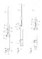
- FIG. 1illustrates the adhesion probe for securing a breast tumor during a biopsy or ablation procedure.
- FIG. 2is a cross section of the adhesion probe of FIG. 1 .
- FIGS. 5 and 6illustrate the biopsy instrument adapted with the adhesion probe of FIGS. 1 and 2.
- FIG. 7illustrates a method of breast tumor biopsy using the device of FIGS. 5 and 6.
- FIG. 8illustrates a method of breast tumor biopsy using the device of FIGS. 5 and 6.
- FIG. 9illustrates a method of breast tumor biopsy using the device of FIGS. 5 and 6.
- FIG. 10illustrates a method of breast tumor biopsy using the device of FIGS. 5 and 6.
- FIG. 11illustrates the adhesion probe withdrawn from the biopsy instrument.
- FIG. 12illustrates the holding tray for holding the adhesion probe.
- FIG. 13illustrates a biopsy gun adapted for use with the adhesion probe of FIG. 1 .
- FIGS. 14 and 15are cross sections of the biopsy gun of FIG. 13 .
- FIG. 18illustrates a method of breast tumor biopsy using the device of FIG. 13 .
- FIG. 20is a cross section of a biopsy gun provided with a gas turbine motor and adapted for use with the adhesion probe of FIG. 1 .
- FIG. 21is a cross section of a biopsy gun provided with a gas turbine motor and adapted for use with the adhesion probe of FIG. 1 .
- FIGS. 22 and 23illustrate an embodiment of the adhesion probe which uses a coolant supplied in small bottles.
- FIG. 2illustrates the adhesion probe 1 in cross section, showing the rigid tube 2 , the distal penetrating segment 3 and the handle 4 .
- a coolant inlet tube 10passes through the handle and the rigid tube, extending to the distal end of the rigid tube, and terminating just proximal of the distal tip of the penetrating segment.
- the inlet tubehas an orifice 11 at the distal end of the inlet tube, which may be merely a straight cut termination of the tube or a small nozzle of smaller internal diameter than the immediately upstream portion of the inlet tube.
- the rigid tubehas a proximal segment 12 having an outer diameter of about (0.065) inches, an internal diameter of about (0.047) inches, and a length of about (10) inches.
- the penetrating segment 3comprises a first segment 13 and a sharp distal tip 14 .
- the first segmenthas an outer diameter of about (0.043) inches, an inner diameter of about (0.033) inches, and a length of about (1) inch.
- the sharp distal tipis solid and adapted for piercing through a tumor.
- the length of the penetrating segmentis chosen to be approximately the same size as the target tissue mass to be sampled, or the size of the desired core sample. This penetrating segment is forced into a lesion or tumor.
- a tapered segment 15 of the rigid tubeof about (0.05) inches long where the inner and outer diameters of the rigid tube tapers from the diameters of the proximal segment to the diameters of the first segment.
- An annular cavity or lumen 16is created by the outer surface of the inlet tube and the inner surface of the rigid tube.
- the gas and/or liquid exiting the orifice of the inlet tubecounterflows along the annular cavity and is exhausted from the probe to a suitable point far removed from the probe. If gas such as Argon is chosen, the gas undergoes a Joule Thompson expansion as the gas is directed out through the orifice.
- the surface area about the penetrating segmentis cooled. Cooling with argon gas supplied to the probe with the dimensions described above at a pressure of about 1200-2000 psi will provide cooling to a temperature range of about 0° C. to ⁇ 10° C. With gas supplied at 3000 psi, the adhesion probe will attain a low temperature of about ⁇ 60° C. in water.
- the gas or liquid used for coolingmay include gaseous argon, nitrogen, carbon dioxide, air, liquid nitrogen, freon, CFC's. perflourocarbons, or any other suitable coolant. Gas may be provided through a cryosurgical system such as Endocare's Cryocare® cryosurgical systems.
- FIG. 4illustrates a spring-loaded biopsy instrument 24 adapted for use with the adhesion probe 1 and the cannula 20 .
- the biopsy instrumentcomprises a housing 25 .
- the housingcomprises a grip 26 , sized for a human hand, and a receptacle 27 distal to the grip.
- a fitting 28 with an inlet 29communicates with the lumen of the cannula.
- the cannulaextends from within the housing at the inlet and out through the distal end of the housing.
- the biopsy instrument 24includes a coring mechanism.
- the coring mechanismcomprises a cannula translating mechanism housed within the receptacle 27 .
- a block 32is slidably mounted on rails 33 attached to or integrally formed to the housing 25 .
- a trigger button 34 capable of coupling with the blockis preferably positioned about the grip 26 for ease of operation of the button by the same hand holding the grip.
- a spring 35is interposed between the block and the trigger button. The spring exerts a distally urging force to the block.
- a stopper 36attached to or integrally formed into the housing.
- the cannula 20is fixedly fitted through the block and urged distally forward by the spring. The distally urging force of the spring forces the block and therefore the cannula to distally translate.
- the springmay have a spring constant between 5 to 15 lbs. per inch, and is preferably between 7 and 11 lbs. per inch.
- FIGS. 5 and 6show the adhesion probe 1 in place within the lumen 23 of the cannula 20 .
- the adhesion probecan be inserted into and through the lumen from the proximal opening 21 of the cannula.
- the handle 4 of the probeis fitted to the fitting 28 .
- the gas and/or liquid sourceis connected to the handle via the feed line.
- Any suitable latching mechanismmay be used to releasably secure the block in the proximal position and release the block as desired by the operator of the device.)
- the block and the cannulatranslate along the rails 33 until the block engages the stopper 36 .
- the cannulatranslates distally over the penetrating segment of the adhesion probe, any tissue stuck to the penetrating segment is cored from the surrounding lesion, and may be removed with the device.
- the adhesion probeis inserted into the biopsy instrument 24 so that it is positioned within the cannula, the penetrating tip 3 extending distally from the distal end of the cannula 20 .
- the cannula translating mechanismis set in the locked position, leaving the penetrating segment outside the cannula.
- the distal end of the deviceincluding the penetrating segment of the adhesion probe and the distal end of the cannula, is inserted into the breast through the incision. The distal end of the device is maneuvered to the target lesion within the breast under stereotactic or ultrasound guidance.
- the tumor, lesion or other suspect mass 41is located within the breast, surrounded by soft tissue and fatty tissue.
- An ultrasound scanner or other imaging deviceis used to obtain an image of the breast, including the tumor and any device inserted into the breast, and the surgeon uses the display from the imaging device to assist in guidance of the probe and the cannula to the tumor.
- FIG. 8illustrates the adhesion probe 1 and the cannula 20 being inserted into the breast 39 until the probe penetrates the tumor 41 .
- the surgeonpushes the probe and the cannula into the breast until the penetrating segment 3 of the adhesion probe pierces through the tumor and until the tapered segment 15 of the rigid tube 2 is proximate to the tumor.
- FIG. 9illustrates the adhesion probe 1 being activated to secure the tumor 41 .
- the surface area about the penetrating segment 3is cooled. Either gas or liquid is directed from the source to the penetrating segment. If the surgeon uses gas, as the gas is directed out through the orifice 11 of the coolant inlet tube 10 , the gas undergoes a Joule-Thomson effect to freeze the surface area about the penetrating segment.
- the gas sourcecan be a high compression tank or a whippet.
- the surface areais frozen to a temperature range of about 0° C. to ⁇ 60° C. At this temperature range, the cooled surface area does not ablate the tumor cells to hinder tumor cell analysis.
- the cooled annular volume of body tissueis illustrated in FIG. 9 as item 42 .
- FIG. 10illustrates activation of the cannula translating mechanism to cut a core sample of the frozen tumor 41 .
- the biopsy instrument 24is activated to core a sample of the frozen tumor.
- the translating mechanismis operated via the trigger button 34 (see FIG. 5 ).
- the trigger buttonis depressed and the cannula 20 advances distally towards the frozen tumor.
- the cannulacontacts the tumor and advances towards the sharp distal tip, the cannula cuts a sample 43 of the frozen tumor.
- the resulting core sampleis a layer of frozen or partially frozen tumor tissue about the penetrating segment 3 . Because the tumor is frozen, dispersion and seeding of the tumor cells to healthy areas of the breast is minimized compared to normal biopsy methods.
- the holding tray 44has a wall 45 which has one or more slots 46 .
- the width of the slotsapproximates the outer diameter of the penetrating segment of the adhesion probe, so that the adhesion probe may be slipped down into the groove and pulled out horizontally, allowing the sample to be cleanly scraped off of the penetrating segment.
- the adhesion probe and holding traymay be provided as disposables in a kit sold for each procedure performed by a physician.
- Another method of using the systemfacilitates multiple sampling during a single placement of the biopsy instrument 24 .
- the adhesion probemay be pulled proximally out of the cannula while leaving the cannula and biopsy instrument in place in the breast 39 .
- the tissue which adheres to the adhesion probeis then removed. Leaving the cannula in the advanced position within the patient's breast, the adhesion probe may then be re-inserted into the cannula (in the same space or biopsy track).
- the cannulais then pulled back, exposing the penetrating segment within the tumor (and within the initial cored space). While light pressure is applied around the breast, the adhesion probe is cooled, freezing an additional cylindrical volume of tissue surrounding the probe. The cannula may then be advanced to core out the frozen volume of tissue. Successive cylindrical core samples are thereby obtained. In our own studies, this procedure yielded seventeen successive cylindrical core samples.
- FIG. 13shows a biopsy gun 50 for use with the adhesion probe of FIG. 1 .
- the biopsy guncomprises a housing 51 , the cannula 20 , and a trigger 52 for driving the cannula distally.
- a snap fitting 53 with an inlet 54communicates with the lumen of the cannula.
- the cannulaextends from within the housing at the inlet and out through the distal end of the housing.
- the cannulais adapted for insertion through a small incision in the skin.
- FIGS. 14 and 15illustrate the biopsy gun in cross section.
- the biopsy gun 50includes a coring mechanism that includes a cannula rotating mechanism and a cannula translating mechanism.
- the cannula rotating mechanismcomprises a motor 57 , a pinion gear 58 , and a drive gear 59 .
- the drive gearhas a bore sized to fit the cannula 20 .
- the cannulais rotationally fixed into the drive gear through the bore, so that rotation of the drive gear results in corresponding rotation of the cannula.
- the pinion gearis rotatably coupled to the motor at one end and its gear teeth mesh with the drive gear. When the motor is activated, the motor causes the pinion gear to rotate.
- the rotation of the pinion gearis translated to the drive gear to rotate the drive gear and thereby rotate the cannula.
- the rotating mechanismmay be used during coring to assist in cutting a core sample from surrounding tissue.
- the cannula translating mechanismcomprises the trigger 52 , trigger upper extension 61 , a pivotable arm 62 with a first end 63 connected to the trigger and a second end 64 connected to a carriage 65 .
- the carriageis slidably mounted in a track 66 via a rail 67 that fits into the track.
- the trackis fixedly attached to the housing 51 , or formed integrally into the housing, and is preferably duplicated on both sides of the housing.
- the railis slidably mounted onto the track with the arm pivotably attached to the carriage at the proximal end of the carriage.
- the triggeris pivotably mounted to the housing about a pivot pin 68 and attached to the first end of the arm.
- the carriageis attached to the second end of the arm.
- the cannula 20is loosely fitted through the carriage.
- the bearings 69are fixed to the cannula on either side of the carriage, and allow the cannula to be rotatable within the carriage but longitudinally locked to the carriage, so that any longitudinal (proximal or distal) movement of the carriage causes corresponding longitudinal movement of the cannula.
- the cannula translating mechanismhas a proximal position and a distal position.
- FIG. 14illustrates the translating mechanism in the proximal position, where the cannula will not be engaged with the tumor.
- the carriage 65In the proximal position, the carriage 65 is positioned at the proximal end of the track 66 and the penetrating segment 3 of the adhesion probe 1 is exposed, extending distally from the cannula.
- FIG. 15illustrates the translating mechanism in the distal position, with the cannula translated distally over the penetrating segment of the adhesion probe, where it will engage and core a tumor secured to the penetrating segment.
- the trigger 53To move the translating mechanism to the distal position, the trigger 53 is depressed.
- the triggerrotates about the pivot pin 68 to advance the arm 62 and the rail 67 to the distal end of the track, thereby also advancing the carriage to the distal end of the track.
- the cannula 20advances from the proximal end of the gun 50 to the distal end of the gun. Any tissue stuck to the tip of the adhesion probe when the cannula is advanced is cored from the surrounding lesion, and may be removed with the device.
- FIG. 15also shows the adhesion probe 1 in place within the lumen 23 of the cannula 20 .
- the adhesion probecan be inserted into and through the lumen from the proximal opening 21 of the cannula.
- the handle 4 of the adhesion probeis snap fitted to the snap fitting 53 .
- the gas and/or liquid sourceis connected to the 10 handle via the feed line.
- FIGS. 16 through 19illustrate the device in use.
- FIG. 16shows the adhesion probe 1 and the cannula 20 being inserted through the incision made in the skin overlying the tumor.
- the patient's breast 78 and skin 79are shown schematically.
- the tumor, lesion or other suspect mass 80is located within the breast, surrounded by soft tissue and fatty tissue.
- An ultrasound scanner or other imaging deviceis used to obtain an image of the breast, including the tumor and any device inserted into the breast, and the surgeon uses the display from the imaging device to assist in guidance of the probe and the cannula to the tumor.
- FIG. 17illustrates the adhesion probe 1 and the cannula 20 being inserted into the breast until the probe penetrates the tumor 80 .
- the surgeonpushes the probe and the cannula into the breast until the penetrating segment 3 of the adhesion probe 1 pierces through the tumor and until the tapered segment 15 of the rigid tube 2 is proximate to the tumor.
- FIG. 18illustrates the adhesion probe 1 being activated to secure the tumor 80 .
- the surface area about the penetrating segment 3is cooled. Either gas or liquid is directed from the source to the penetrating segment. If the surgeon uses gas, as the gas is directed out through the orifice 11 of the coolant inlet tube, the gas undergoes a Joule-Thomson effect to freeze the surface area about the penetrating segment.
- the cooled annular volume of body tissueis illustrated in FIG. 18 as item 81 .
- the gas sourcecan be a high compression tank or a whippet.
- the surface areais frozen to a temperature range of about 0° C. to ⁇ 60° C.
- the cooled surface areadoes not ablate the tumor cells to hinder tumor cell analysis. Only a relatively small amount of gas or liquid is needed to cool the surface area to this temperature range.
- the gas or liquid exiting the orifice and counterflowing along,the annular cavity 16is exhausted from the probe.
- the cooled surface areafreezes a thin layer of tumor cells in contact about the cooled surface area, and the tumor is secured to the probe.
- FIG. 19illustrates activation of the coring mechanisms to cut a core sample of the frozen tumor 80 .
- the biopsy gunis activated to core a sample of the frozen tumor.
- the rotating mechanism of the gunmay be activated while the translating mechanism is still in the proximal position.
- the translating mechanismis operated via the trigger.
- the triggeris depressed and the cannula advances distally towards the frozen tumor.
- the rotating cannulacuts a sample of the frozen tumor.
- the resulting core sampleis a layer of frozen or partially frozen tumor tissue about the penetrating segment 3 . Because the tumor is frozen, dispersion and seeding of the tumor cells to healthy areas of the breast is minimized compared to normal biopsy methods.
- the coring mechanismis deactivated with the cannula remaining in the distal position.
- the adhesion probe 1 with the secured core sampleremains within the cannula.
- the biopsy gun and the adhesion probeare retracted from the breast, with the core sample still protected within the cannula during retraction.
- the adhesion probe with the core sample 43is withdrawn from the gun out from the inlet 10 , or out the distal end of the cannula, as shown in FIG. 11 .
- the sampleis still secured to the distal segment of the adhesion probe 1 , and can be removed as previously illustrated in FIG. 12 .
- FIG. 20illustrates an alternative coring mechanism, showing a gas turbine 83 in place of the motor of the previous figures.
- This turbineis powered by the exhaust gas from the adhesion probe, thereby eliminating the need for an electric motor.
- a flexible tube 84is connected to the exhaust pathway of the adhesion probe or gas supply line through a coupling 85 , and is also coupled to the turbine, directing exhaust gas into the turbine.
- a suitable turbine gas control valve 86may be used to control gas supply to the turbine.
- the cannula 20is rotatably coupled to the gas turbine using the same type of pinion gear and drive gear arrangement as is used for the electric motor.
- FIGS. 20 and 21illustrates another embodiment of the turbine driven coring mechanism, in which the turbine is mounted directly on the cannula, in the place of the carriage of the previous embodiments, and is slidably mounted within the housing.
- the tubing 87is flexible, allowing distal and proximal translation of the turbine during operation.
- the turbine driven devices of FIGS. 20 and 21may be used in the same manner as the biopsy instruments and guns of FIGS. 4 and 13.
- the adhesion probe and methods of use described abovehave been developed for use with a cryosurgical system, which controls a relatively high volume coolant source, and can also be used to operate cryoprobes to cryoablate lesions, tumors and other target masses in the breast.
- the adhesion probe and biopsy apparatusbiological instrument and biopsy gun
- biopsy instrument and biopsy gunare conveniently combined with such pre-existing cryosurgical system to take advantage of cooling sources already in place in an operating room.
- the adhesion probes and biopsy devices of FIGS. 22 and 23, however,are designed for stand-alone use, so that a physician does not need a cryosurgical system on site in order to take advantage of the method of cryo-adhesion.
- FIG. 22illustrates a self-contained adhesion probe.
- the self-contained adhesion probeincludes the rigid tube 2 with the penetrating segment 3 . Inside the rigid tube, coolant inlet tube 10 with an orifice 11 extends to the first segment 13 of the penetrating segment. At the proximal end of the rigid tube, screw threads or other releasable fittings are provided to permit releasable attachment to the gas source.
- the rigid tubeis fitted with a sharp distal tip 14 . Exhaust gas is vented through vent 88 on the proximal segment of the rigid tube.
- the gas sourceis provided in the form of a canister 89 of compressed gas. Carbon dioxide (CO 2 ) is a suitable gas, and is readily available in the form of cylinders (whippet chargers, bulbs or capsules).
- Liquid freon and other refrigerantsare also a suitable coolants which can be obtained in small canisters or spray cans.
- the canisteris releasably mounted into a bracket or holder 90 .
- the holderhas a fitting 91 for receiving the proximal end of the rigid rod and providing secure releasable attachment.
- the holderas a second fitting 92 which matches the fittings on the proximal end of the biopsy apparatuses.
- the output 93 of the canisteris directed to the inlet 94 of the coolant inlet tube 10 through the pass-through port in the holder.
- the rigid tubemay be removed from the gas source and holder to provide a simple needle configuration.
- This assemblycan be used in much the same was as the embodiments using a gas hose (FIGS. 7-10 and 16 - 19 ), but may also be used in an “over-the-wire” method.
- the rigid rodis manipulated to penetrate the patient's breast and force the penetrating segment into the lesion.
- the biopsy apparatusis then threaded over the rigid tube, leaving the proximal end of the rigid tube extending slightly from the proximal end of the biopsy apparatus.
- the coolant holderis then threaded or otherwise secured onto the proximal end of the rigid tube, and the proximal releasable fitting is fitted into the receiving fitting on the holder.
- the cooling and coring stepsare then accomplished as described above. This method permits easier manipulation of the adhesion probe into the tumor, and also eliminates reliance on large cryosurgical systems.
- coring means, translating means, and rotating meanscan be used in place of the spring operated translating means of FIGS. 4 through 6 or the translating means and rotating means of FIGS. 13 through 15.
- the cannulacan be fitted with a slide bolt, for example, which can then be manually pushed distally in the holders to advance the cannula.
- the cannulamay merely be forced over the adhesion probe by hand, without the assistance of the coring mechanisms.
- the adhesion probehas been described in embodiments which use coolants to cool the probe and target tissue and thereby make the probe adhere to the target tissue.
- heating elementssuch as RF heating elements, resistive heating elements, ultrasound heating elements and the like may be used to heat the probe and target tissue and thereby make the probe adhere to the target tissue.
- the heatingshould be limited to that necessary for light necrosis of the target tissue that does not penetrate deeply into the target tissue, or to a small longitudinal segment of the tissue, so that a viable biopsy core may be obtained. However, if the entire tumor or lesion is to be removed with the aid of the adhesion probe, heating need not be so limited.
- the devices and methods illustrated abovehave been illustrated in relation to the treatment of tumors and lesions within the breast. However, they may be used to treat tumors and lesions throughout the body wherever the tumors which are difficult to secure and locate are encountered. Thus the devices and methods may be used for tumors and lesions of the uterine tube (such as uterine fibroids), kidney, liver, prostate or brain.
- the uterine tubesuch as uterine fibroids
Landscapes
- Health & Medical Sciences (AREA)
- Life Sciences & Earth Sciences (AREA)
- Medical Informatics (AREA)
- Engineering & Computer Science (AREA)
- Biomedical Technology (AREA)
- Heart & Thoracic Surgery (AREA)
- Pathology (AREA)
- Molecular Biology (AREA)
- Surgery (AREA)
- Animal Behavior & Ethology (AREA)
- General Health & Medical Sciences (AREA)
- Public Health (AREA)
- Veterinary Medicine (AREA)
- Surgical Instruments (AREA)
- Investigating Or Analysing Biological Materials (AREA)
Abstract
Description
Claims (6)
Priority Applications (15)
| Application Number | Priority Date | Filing Date | Title |
|---|---|---|---|
| US09/690,321US6540694B1 (en) | 2000-10-16 | 2000-10-16 | Device for biopsy tumors |
| US09/847,931US6551255B2 (en) | 2000-10-16 | 2001-05-03 | Device for biopsy of tumors |
| AU2002211568AAU2002211568B2 (en) | 2000-10-16 | 2001-10-09 | Device for biopsy of tumors |
| EP01979631AEP1333759B1 (en) | 2000-10-16 | 2001-10-09 | Device for biopsy of tumors |
| DE60141762TDE60141762D1 (en) | 2000-10-16 | 2001-10-09 | TUMOR BIOPSY DEVICE |
| JP2002535557AJP4108473B2 (en) | 2000-10-16 | 2001-10-09 | Tumor biopsy device |
| PCT/US2001/031579WO2002032318A1 (en) | 2000-10-16 | 2001-10-09 | Device for biopsy of tumors |
| AU1156802AAU1156802A (en) | 2000-10-16 | 2001-10-09 | Device for biopsy of tumors |
| BR0114716-1ABR0114716A (en) | 2000-10-16 | 2001-10-09 | Tumor biopsy device |
| CA002425793ACA2425793A1 (en) | 2000-10-16 | 2001-10-09 | Device for biopsy of tumors |
| AT01979631TATE463203T1 (en) | 2000-10-16 | 2001-10-09 | TUMOR BIOPSY DEVICE |
| US10/421,598US7311672B2 (en) | 2000-10-16 | 2003-04-22 | Device for biopsy of tumors |
| AU2005232255AAU2005232255B2 (en) | 2000-10-16 | 2005-11-09 | Device for biopsy of tumors |
| US11/964,244US20080103411A1 (en) | 2000-10-16 | 2007-12-26 | Device for Biopsy of Tumors |
| US12/883,572US20110066075A1 (en) | 2000-10-16 | 2010-09-16 | Device for Biopsy of Tumors |
Applications Claiming Priority (1)
| Application Number | Priority Date | Filing Date | Title |
|---|---|---|---|
| US09/690,321US6540694B1 (en) | 2000-10-16 | 2000-10-16 | Device for biopsy tumors |
Related Child Applications (1)
| Application Number | Title | Priority Date | Filing Date |
|---|---|---|---|
| US09/847,931Continuation-In-PartUS6551255B2 (en) | 2000-10-16 | 2001-05-03 | Device for biopsy of tumors |
Publications (1)
| Publication Number | Publication Date |
|---|---|
| US6540694B1true US6540694B1 (en) | 2003-04-01 |
Family
ID=24772013
Family Applications (2)
| Application Number | Title | Priority Date | Filing Date |
|---|---|---|---|
| US09/690,321Expired - LifetimeUS6540694B1 (en) | 2000-10-16 | 2000-10-16 | Device for biopsy tumors |
| US09/847,931Expired - LifetimeUS6551255B2 (en) | 2000-10-16 | 2001-05-03 | Device for biopsy of tumors |
Family Applications After (1)
| Application Number | Title | Priority Date | Filing Date |
|---|---|---|---|
| US09/847,931Expired - LifetimeUS6551255B2 (en) | 2000-10-16 | 2001-05-03 | Device for biopsy of tumors |
Country Status (3)
| Country | Link |
|---|---|
| US (2) | US6540694B1 (en) |
| AT (1) | ATE463203T1 (en) |
| DE (1) | DE60141762D1 (en) |
Cited By (91)
| Publication number | Priority date | Publication date | Assignee | Title |
|---|---|---|---|---|
| US20030195436A1 (en)* | 2000-10-16 | 2003-10-16 | Sanarus Medical Incorporated | Device for biopsy of tumors |
| US20030208135A1 (en)* | 2002-05-03 | 2003-11-06 | Kenneth Bloom | Method and system for biopsy and analysis of body tissue |
| US20030225411A1 (en)* | 2002-05-31 | 2003-12-04 | Vidacare Corporation | Apparatus and method to access bone marrow |
| US20050131345A1 (en)* | 2002-05-31 | 2005-06-16 | Larry Miller | Apparatus and method for accessing the bone marrow of the sternum |
| US20050148940A1 (en)* | 2002-05-31 | 2005-07-07 | Larry Miller | Apparatus and method for accessing the bone marrow |
| US20050261693A1 (en)* | 2002-05-31 | 2005-11-24 | Miller Larry J | Apparatus and method to inject fluids into bone marrow and other target sites |
| US20050288684A1 (en)* | 2004-06-16 | 2005-12-29 | Aronson Nathan A | Method of reducing collateral flow in a portion of a lung |
| US20050288550A1 (en)* | 2004-06-14 | 2005-12-29 | Pneumrx, Inc. | Lung access device |
| US20060025815A1 (en)* | 2004-07-08 | 2006-02-02 | Mcgurk Erin | Lung device with sealing features |
| US20060173377A1 (en)* | 2005-01-31 | 2006-08-03 | Mccullough Adam B | Quick cycle biopsy system |
| US20060229528A1 (en)* | 2003-03-29 | 2006-10-12 | C. R. Brad, Inc. | Coaxial cannula provided with a sealing element |
| US20070016100A1 (en)* | 2002-05-31 | 2007-01-18 | Miller Larry J | Apparatus and Methods to Harvest Bone and Bone Marrow |
| US20070049945A1 (en)* | 2002-05-31 | 2007-03-01 | Miller Larry J | Apparatus and methods to install, support and/or monitor performance of intraosseous devices |
| US20070149893A1 (en)* | 2002-03-19 | 2007-06-28 | C.R. Bard, Inc. | Biopsy device and biopsy needle module that can be inserted into the biopsy device |
| US20070156125A1 (en)* | 2005-12-30 | 2007-07-05 | Russell Delonzor | Encodable cryogenic device |
| US20070213755A1 (en)* | 2006-03-07 | 2007-09-13 | Beckman Andrew T | Device for minimally invasive internal tissue removal |
| US20070213630A1 (en)* | 2006-03-07 | 2007-09-13 | Beckman Andrew T | Device for minimally invasive internal tissue removal |
| US20070239064A1 (en)* | 2006-03-29 | 2007-10-11 | Cicenas Chris W | Device for minimally invasive internal tissue removal |
| US20070243657A1 (en)* | 2006-04-13 | 2007-10-18 | Basol Bulent M | Method and Apparatus to Form Thin Layers of Materials on a Base |
| US20070270775A1 (en)* | 2004-11-12 | 2007-11-22 | Miller Larry J | Intraosseous Device And Methods For Accessing Bone Marrow In The Sternum And Other Target Areas |
| US20080045965A1 (en)* | 2002-05-31 | 2008-02-21 | Miller Larry J | Apparatus and Methods for Biopsy and Aspiration of Bone Marrow |
| US20080045857A1 (en)* | 2002-05-31 | 2008-02-21 | Miller Larry J | Bone Marrow Aspiration Devices and Related Methods |
| US20080045860A1 (en)* | 2002-05-31 | 2008-02-21 | Miller Larry J | Biopsy Devices and Related Methods |
| US20080215056A1 (en)* | 2002-05-31 | 2008-09-04 | Miller Larry J | Powered Drivers, Intraosseous Devices And Methods To Access Bone Marrow |
| US20080281225A1 (en)* | 2004-02-12 | 2008-11-13 | Spero Richard K | Rotational Core Biopsy Device With Liquid Cryogen Adhesion Probe |
| US20090036823A1 (en)* | 2007-07-30 | 2009-02-05 | Lepivert Patrick | Fluid flowing device and method for tissue diagnosis or therapy |
| US20090045084A1 (en)* | 2004-08-26 | 2009-02-19 | G.D Societa Per Azioni | Rigid hinged-lid package for tobacco articles |
| US20090050516A1 (en)* | 2007-08-20 | 2009-02-26 | Hardin Terry D | Tissue collection tray |
| US20090076622A1 (en)* | 2006-03-13 | 2009-03-19 | Pneumrx, Inc. | Delivery of Minimally Invasive Lung Volume Reduction Devices |
| USD601247S1 (en) | 2007-08-20 | 2009-09-29 | Suros Surgical Systems, Inc. | Tissue collection tray |
| US20100106055A1 (en)* | 2002-03-19 | 2010-04-29 | C.R. Bard, Inc. | Biopsy device having a vacuum pump |
| US20100160813A1 (en)* | 2007-09-10 | 2010-06-24 | University Of Yamanashi | Medical apparatus and living tissue freezing and harvesting apparatus |
| US20100169724A1 (en)* | 2005-02-09 | 2010-07-01 | Interdigital Technology Corporation | Method and system for recognizing radio link failures associated with hsupa and hsdpa channels |
| US7762961B2 (en) | 2003-03-29 | 2010-07-27 | C. R. Bard, Inc. | Pressure generating unit |
| US7766938B2 (en) | 2004-07-08 | 2010-08-03 | Pneumrx, Inc. | Pleural effusion treatment device, method and material |
| US20100198202A1 (en)* | 2007-06-26 | 2010-08-05 | Klaus Fischer | Cryobiopsy probe |
| US7815642B2 (en) | 2004-01-26 | 2010-10-19 | Vidacare Corporation | Impact-driven intraosseous needle |
| US20100274178A1 (en)* | 2007-07-30 | 2010-10-28 | Lepivert Patrick | Fluid flowing device and method for tissue diagnosis or therapy |
| US20100298784A1 (en)* | 2004-01-26 | 2010-11-25 | Miller Larry J | Manual Intraosseous Device |
| US20110004120A1 (en)* | 2009-05-28 | 2011-01-06 | Angiotech Pharmaceuticals Inc. | Biopsy device needle set |
| US20110054349A1 (en)* | 2007-12-27 | 2011-03-03 | Devicor Medical Products, Inc. | Clutch and valving system for tetherless biopsy device |
| US20110184312A1 (en)* | 2008-08-14 | 2011-07-28 | Moran Jr Antonio | Bone Tissue Extracting Device and Method |
| US8052615B2 (en) | 2004-07-09 | 2011-11-08 | Bard Peripheral Vascular, Inc. | Length detection system for biopsy device |
| US8251917B2 (en) | 2006-08-21 | 2012-08-28 | C. R. Bard, Inc. | Self-contained handheld biopsy needle |
| US8262585B2 (en) | 2005-08-10 | 2012-09-11 | C. R. Bard, Inc. | Single-insertion, multiple sampling biopsy device with linear drive |
| US8262586B2 (en) | 2006-10-24 | 2012-09-11 | C. R. Bard, Inc. | Large sample low aspect ratio biopsy needle |
| US8267868B2 (en) | 2005-08-10 | 2012-09-18 | C. R. Bard, Inc. | Single-insertion, multiple sample biopsy device with integrated markers |
| US8282574B2 (en) | 2005-08-10 | 2012-10-09 | C. R. Bard, Inc. | Single-insertion, multiple sampling biopsy device usable with various transport systems and integrated markers |
| US8430824B2 (en) | 2009-10-29 | 2013-04-30 | Bard Peripheral Vascular, Inc. | Biopsy driver assembly having a control circuit for conserving battery power |
| US8485987B2 (en) | 2006-10-06 | 2013-07-16 | Bard Peripheral Vascular, Inc. | Tissue handling system with reduced operator exposure |
| US8485989B2 (en) | 2009-09-01 | 2013-07-16 | Bard Peripheral Vascular, Inc. | Biopsy apparatus having a tissue sample retrieval mechanism |
| US8597205B2 (en) | 2007-12-20 | 2013-12-03 | C. R. Bard, Inc. | Biopsy device |
| US8597206B2 (en) | 2009-10-12 | 2013-12-03 | Bard Peripheral Vascular, Inc. | Biopsy probe assembly having a mechanism to prevent misalignment of components prior to installation |
| US8632605B2 (en) | 2008-09-12 | 2014-01-21 | Pneumrx, Inc. | Elongated lung volume reduction devices, methods, and systems |
| US8641715B2 (en) | 2002-05-31 | 2014-02-04 | Vidacare Corporation | Manual intraosseous device |
| US8656929B2 (en) | 2002-05-31 | 2014-02-25 | Vidacare Corporation | Medical procedures trays and related methods |
| US8690793B2 (en) | 2009-03-16 | 2014-04-08 | C. R. Bard, Inc. | Biopsy device having rotational cutting |
| US8690791B2 (en) | 2002-05-31 | 2014-04-08 | Vidacare Corporation | Apparatus and method to access the bone marrow |
| US8708929B2 (en) | 2009-04-15 | 2014-04-29 | Bard Peripheral Vascular, Inc. | Biopsy apparatus having integrated fluid management |
| US8721734B2 (en) | 2009-05-18 | 2014-05-13 | Pneumrx, Inc. | Cross-sectional modification during deployment of an elongate lung volume reduction device |
| US8740921B2 (en) | 2006-03-13 | 2014-06-03 | Pneumrx, Inc. | Lung volume reduction devices, methods, and systems |
| US8845548B2 (en) | 2009-06-12 | 2014-09-30 | Devicor Medical Products, Inc. | Cutter drive assembly for biopsy device |
| US8944069B2 (en) | 2006-09-12 | 2015-02-03 | Vidacare Corporation | Assemblies for coupling intraosseous (IO) devices to powered drivers |
| US8968210B2 (en) | 2008-10-01 | 2015-03-03 | Covidien LLP | Device for needle biopsy with integrated needle protection |
| US8974410B2 (en) | 2006-10-30 | 2015-03-10 | Vidacare LLC | Apparatus and methods to communicate fluids and/or support intraosseous devices |
| US9072543B2 (en) | 2002-05-31 | 2015-07-07 | Vidacare LLC | Vascular access kits and methods |
| US9125639B2 (en) | 2004-11-23 | 2015-09-08 | Pneumrx, Inc. | Steerable device for accessing a target site and methods |
| US9173641B2 (en) | 2009-08-12 | 2015-11-03 | C. R. Bard, Inc. | Biopsy apparatus having integrated thumbwheel mechanism for manual rotation of biopsy cannula |
| US9186128B2 (en) | 2008-10-01 | 2015-11-17 | Covidien Lp | Needle biopsy device |
| US9332973B2 (en) | 2008-10-01 | 2016-05-10 | Covidien Lp | Needle biopsy device with exchangeable needle and integrated needle protection |
| US9402633B2 (en) | 2006-03-13 | 2016-08-02 | Pneumrx, Inc. | Torque alleviating intra-airway lung volume reduction compressive implant structures |
| US9504477B2 (en) | 2003-05-30 | 2016-11-29 | Vidacare LLC | Powered driver |
| US9510910B2 (en) | 2006-09-12 | 2016-12-06 | Vidacare LLC | Medical procedures trays and related methods |
| US9782565B2 (en) | 2008-10-01 | 2017-10-10 | Covidien Lp | Endoscopic ultrasound-guided biliary access system |
| US10285673B2 (en) | 2013-03-20 | 2019-05-14 | Bard Peripheral Vascular, Inc. | Biopsy device |
| US10390838B1 (en) | 2014-08-20 | 2019-08-27 | Pneumrx, Inc. | Tuned strength chronic obstructive pulmonary disease treatment |
| US10456120B2 (en) | 2013-11-05 | 2019-10-29 | C. R. Bard, Inc. | Biopsy device having integrated vacuum |
| US10463350B2 (en) | 2015-05-01 | 2019-11-05 | C. R. Bard, Inc. | Biopsy device |
| CN111481286A (en)* | 2020-04-23 | 2020-08-04 | 中国人民解放军陆军特色医学中心 | Wart body freezing device |
| US10973532B2 (en) | 2002-05-31 | 2021-04-13 | Teleflex Life Sciences Limited | Powered drivers, intraosseous devices and methods to access bone marrow |
| US10973545B2 (en) | 2002-05-31 | 2021-04-13 | Teleflex Life Sciences Limited | Powered drivers, intraosseous devices and methods to access bone marrow |
| US11116483B2 (en) | 2017-05-19 | 2021-09-14 | Merit Medical Systems, Inc. | Rotating biopsy needle |
| US11298113B2 (en) | 2008-10-01 | 2022-04-12 | Covidien Lp | Device for needle biopsy with integrated needle protection |
| US11298202B2 (en) | 2002-05-31 | 2022-04-12 | Teleflex Life Sciences Limited | Biopsy devices and related methods |
| US11337728B2 (en) | 2002-05-31 | 2022-05-24 | Teleflex Life Sciences Limited | Powered drivers, intraosseous devices and methods to access bone marrow |
| US11357515B2 (en)* | 2017-09-09 | 2022-06-14 | June Access Ip, Llc | Intraosseous device having retractable motor/stylet assembly and automatic stylet point cover upon retraction operation |
| US11484339B2 (en)* | 2017-09-09 | 2022-11-01 | June Access, IP LLC | Passive safety intraosseous device |
| US11793498B2 (en) | 2017-05-19 | 2023-10-24 | Merit Medical Systems, Inc. | Biopsy needle devices and methods of use |
| US11844500B2 (en) | 2017-05-19 | 2023-12-19 | Merit Medical Systems, Inc. | Semi-automatic biopsy needle device and methods of use |
| US12150627B2 (en) | 2019-12-11 | 2024-11-26 | Merit Medical Systems, Inc. | Bone biopsy device and related methods |
| US12295556B2 (en) | 2019-09-27 | 2025-05-13 | Merit Medical Systems, Inc. | Rotation biopsy system and handle |
Families Citing this family (97)
| Publication number | Priority date | Publication date | Assignee | Title |
|---|---|---|---|---|
| US7637948B2 (en) | 1997-10-10 | 2009-12-29 | Senorx, Inc. | Tissue marking implant |
| US8668737B2 (en) | 1997-10-10 | 2014-03-11 | Senorx, Inc. | Tissue marking implant |
| US6725083B1 (en) | 1999-02-02 | 2004-04-20 | Senorx, Inc. | Tissue site markers for in VIVO imaging |
| US7983734B2 (en) | 2003-05-23 | 2011-07-19 | Senorx, Inc. | Fibrous marker and intracorporeal delivery thereof |
| US9820824B2 (en) | 1999-02-02 | 2017-11-21 | Senorx, Inc. | Deployment of polysaccharide markers for treating a site within a patent |
| US7651505B2 (en) | 2002-06-17 | 2010-01-26 | Senorx, Inc. | Plugged tip delivery for marker placement |
| US8361082B2 (en) | 1999-02-02 | 2013-01-29 | Senorx, Inc. | Marker delivery device with releasable plug |
| US6862470B2 (en) | 1999-02-02 | 2005-03-01 | Senorx, Inc. | Cavity-filling biopsy site markers |
| US20090030309A1 (en) | 2007-07-26 | 2009-01-29 | Senorx, Inc. | Deployment of polysaccharide markers |
| US8498693B2 (en) | 1999-02-02 | 2013-07-30 | Senorx, Inc. | Intracorporeal marker and marker delivery device |
| US6575991B1 (en) | 1999-06-17 | 2003-06-10 | Inrad, Inc. | Apparatus for the percutaneous marking of a lesion |
| CA2659518A1 (en) | 2000-11-20 | 2002-05-30 | Senorx, Inc. | Tissue site markers for in vivo imaging |
| US20030050648A1 (en) | 2001-09-11 | 2003-03-13 | Spiration, Inc. | Removable lung reduction devices, systems, and methods |
| US6592594B2 (en) | 2001-10-25 | 2003-07-15 | Spiration, Inc. | Bronchial obstruction device deployment system and method |
| US20030216769A1 (en) | 2002-05-17 | 2003-11-20 | Dillard David H. | Removable anchored lung volume reduction devices and methods |
| US20030181922A1 (en) | 2002-03-20 | 2003-09-25 | Spiration, Inc. | Removable anchored lung volume reduction devices and methods |
| US20030195511A1 (en)* | 2002-04-16 | 2003-10-16 | Spiration, Inc. | Device for and method of removing deleterious body tissue from a site within a patient |
| US20060036158A1 (en) | 2003-11-17 | 2006-02-16 | Inrad, Inc. | Self-contained, self-piercing, side-expelling marking apparatus |
| US7087051B2 (en)* | 2003-01-15 | 2006-08-08 | Boston Scientific Scimed, Inc. | Articulating radio frequency probe handle |
| US7100616B2 (en) | 2003-04-08 | 2006-09-05 | Spiration, Inc. | Bronchoscopic lung volume reduction method |
| US7877133B2 (en) | 2003-05-23 | 2011-01-25 | Senorx, Inc. | Marker or filler forming fluid |
| US7533671B2 (en) | 2003-08-08 | 2009-05-19 | Spiration, Inc. | Bronchoscopic repair of air leaks in a lung |
| US8048003B2 (en) | 2003-10-14 | 2011-11-01 | Suros Surgical Systems, Inc. | Vacuum assisted biopsy device |
| JP4500315B2 (en)* | 2003-10-14 | 2010-07-14 | シュロス・サージカル・システムズ・インコーポレーテッド | Vacuum assisted biopsy needle set |
| US8357103B2 (en) | 2003-10-14 | 2013-01-22 | Suros Surgical Systems, Inc. | Vacuum assisted biopsy needle set |
| US7988642B2 (en)* | 2003-10-14 | 2011-08-02 | Suros Surgical Systems, Inc. | Vacuum assisted biopsy device |
| US20050273002A1 (en) | 2004-06-04 | 2005-12-08 | Goosen Ryan L | Multi-mode imaging marker |
| US20050203416A1 (en)* | 2004-03-10 | 2005-09-15 | Angelsen Bjorn A. | Extended, ultrasound real time 2D imaging probe for insertion into the body |
| US20090247879A1 (en)* | 2004-03-09 | 2009-10-01 | Angelsen Bjorn A J | Extended ultrasound imaging probe for insertion into the body |
| US8568334B2 (en)* | 2004-05-11 | 2013-10-29 | Inrad, Inc. | Core biopsy device |
| US20080281226A1 (en)* | 2004-05-11 | 2008-11-13 | Inrad, Inc. | Core Biopsy Device with Specimen Length Adjustment |
| CA2506961C (en)* | 2004-05-11 | 2013-05-07 | Inrad, Inc. | Core biopsy device |
| EP1759638B1 (en)* | 2004-05-11 | 2009-04-08 | Inrad, Inc. | Core biopsy device |
| US8419656B2 (en) | 2004-11-22 | 2013-04-16 | Bard Peripheral Vascular, Inc. | Post decompression marker introducer system |
| US7577473B2 (en) | 2005-02-03 | 2009-08-18 | Bard Peripheral Vascular, Inc. | Apparatus for subcutaneous placement of an imaging marker |
| US10357328B2 (en) | 2005-04-20 | 2019-07-23 | Bard Peripheral Vascular, Inc. and Bard Shannon Limited | Marking device with retractable cannula |
| US20070055173A1 (en)* | 2005-08-23 | 2007-03-08 | Sanarus Medical, Inc. | Rotational core biopsy device with liquid cryogen adhesion probe |
| US8052658B2 (en) | 2005-10-07 | 2011-11-08 | Bard Peripheral Vascular, Inc. | Drug-eluting tissue marker |
| US20070191732A1 (en)* | 2006-02-10 | 2007-08-16 | Voegele James W | Cryogenic probe |
| US7691151B2 (en) | 2006-03-31 | 2010-04-06 | Spiration, Inc. | Articulable Anchor |
| KR101039758B1 (en) | 2006-04-28 | 2011-06-09 | 젤티크 애스세틱스, 인코포레이티드. | Cryoprotectants for use with therapeutic devices for improved cooling of subcutaneous lipid-rich cells |
| US20140025056A1 (en)* | 2006-05-24 | 2014-01-23 | Kambiz Dowlatshahi | Image-guided removal and thermal therapy of breast cancer |
| US8192474B2 (en) | 2006-09-26 | 2012-06-05 | Zeltiq Aesthetics, Inc. | Tissue treatment methods |
| US9132031B2 (en) | 2006-09-26 | 2015-09-15 | Zeltiq Aesthetics, Inc. | Cooling device having a plurality of controllable cooling elements to provide a predetermined cooling profile |
| US20080077201A1 (en) | 2006-09-26 | 2008-03-27 | Juniper Medical, Inc. | Cooling devices with flexible sensors |
| WO2008051749A2 (en) | 2006-10-23 | 2008-05-02 | C. R. Bard, Inc. | Breast marker |
| US9579077B2 (en) | 2006-12-12 | 2017-02-28 | C.R. Bard, Inc. | Multiple imaging mode tissue marker |
| WO2008076973A2 (en) | 2006-12-18 | 2008-06-26 | C.R.Bard Inc. | Biopsy marker with in situ-generated imaging properties |
| US20080287839A1 (en) | 2007-05-18 | 2008-11-20 | Juniper Medical, Inc. | Method of enhanced removal of heat from subcutaneous lipid-rich cells and treatment apparatus having an actuator |
| US8523927B2 (en) | 2007-07-13 | 2013-09-03 | Zeltiq Aesthetics, Inc. | System for treating lipid-rich regions |
| WO2009026471A1 (en) | 2007-08-21 | 2009-02-26 | Zeltiq Aesthetics, Inc. | Monitoring the cooling of subcutaneous lipid-rich cells, such as the cooling of adipose tissue |
| WO2009099767A2 (en) | 2008-01-31 | 2009-08-13 | C.R. Bard, Inc. | Biopsy tissue marker |
| US9327061B2 (en) | 2008-09-23 | 2016-05-03 | Senorx, Inc. | Porous bioabsorbable implant |
| US8603073B2 (en)* | 2008-12-17 | 2013-12-10 | Zeltiq Aesthetics, Inc. | Systems and methods with interrupt/resume capabilities for treating subcutaneous lipid-rich cells |
| EP4215147A3 (en) | 2008-12-30 | 2023-10-18 | C. R. Bard, Inc. | Marker delivery device for tissue marker placement |
| DE102009018291A1 (en) | 2009-04-21 | 2010-10-28 | Erbe Elektromedizin Gmbh | Cryosurgical instrument |
| CA2760610C (en)* | 2009-04-30 | 2017-09-19 | Zeltiq Aesthetics, Inc. | Device, system and method of removing heat from subcutaneous lipid-rich cells |
| CA2787374A1 (en)* | 2010-01-25 | 2011-07-28 | Zeltiq Aesthetics, Inc. | Home-use applicators for non-invasively removing heat from subcutaneous lipid-rich cells via phase change coolants, and associated devices, systems and methods |
| WO2011104692A2 (en) | 2010-02-25 | 2011-09-01 | Robin Medical Inc. | Cryogenic biopsy system and method |
| US10702251B2 (en) | 2010-02-25 | 2020-07-07 | Robin Medical Inc. | Cryogenic biopsy system and method |
| US20110224576A1 (en)* | 2010-03-12 | 2011-09-15 | Biotex, Inc. | Methods and devices for tissue collection and analysis |
| US8676338B2 (en) | 2010-07-20 | 2014-03-18 | Zeltiq Aesthetics, Inc. | Combined modality treatment systems, methods and apparatus for body contouring applications |
| KR101038289B1 (en) | 2010-10-28 | 2011-06-01 | 이상철 | Surgical Residue Extraction Device and Method |
| US8795241B2 (en) | 2011-05-13 | 2014-08-05 | Spiration, Inc. | Deployment catheter |
| WO2014186319A1 (en)* | 2013-05-13 | 2014-11-20 | The Johns Hopkins University | Encapsulated cryoprobe for flexible bronchoscope |
| US9844460B2 (en) | 2013-03-14 | 2017-12-19 | Zeltiq Aesthetics, Inc. | Treatment systems with fluid mixing systems and fluid-cooled applicators and methods of using the same |
| US9545523B2 (en) | 2013-03-14 | 2017-01-17 | Zeltiq Aesthetics, Inc. | Multi-modality treatment systems, methods and apparatus for altering subcutaneous lipid-rich tissue |
| USD716451S1 (en) | 2013-09-24 | 2014-10-28 | C. R. Bard, Inc. | Tissue marker for intracorporeal site identification |
| USD716450S1 (en) | 2013-09-24 | 2014-10-28 | C. R. Bard, Inc. | Tissue marker for intracorporeal site identification |
| USD715442S1 (en) | 2013-09-24 | 2014-10-14 | C. R. Bard, Inc. | Tissue marker for intracorporeal site identification |
| USD715942S1 (en) | 2013-09-24 | 2014-10-21 | C. R. Bard, Inc. | Tissue marker for intracorporeal site identification |
| US20150216719A1 (en) | 2014-01-31 | 2015-08-06 | Zeltiq Aesthetics, Inc | Treatment systems and methods for treating cellulite and for providing other treatments |
| US10675176B1 (en) | 2014-03-19 | 2020-06-09 | Zeltiq Aesthetics, Inc. | Treatment systems, devices, and methods for cooling targeted tissue |
| USD777338S1 (en) | 2014-03-20 | 2017-01-24 | Zeltiq Aesthetics, Inc. | Cryotherapy applicator for cooling tissue |
| US10952891B1 (en) | 2014-05-13 | 2021-03-23 | Zeltiq Aesthetics, Inc. | Treatment systems with adjustable gap applicators and methods for cooling tissue |
| US10568759B2 (en) | 2014-08-19 | 2020-02-25 | Zeltiq Aesthetics, Inc. | Treatment systems, small volume applicators, and methods for treating submental tissue |
| US10935174B2 (en) | 2014-08-19 | 2021-03-02 | Zeltiq Aesthetics, Inc. | Stress relief couplings for cryotherapy apparatuses |
| US11020098B2 (en)* | 2014-09-09 | 2021-06-01 | Boston Scientific Scimed, Inc. | Methods, systems and devices for cryogenic biopsy |
| WO2016086284A1 (en)* | 2014-12-03 | 2016-06-09 | Synaptive Medical (Barbados) Inc. | Tumor stabilizing apparatus for a medical procedure |
| US10517608B2 (en)* | 2015-08-27 | 2019-12-31 | Acclarent, Inc. | Apparatus to form opening in ethmoid bulla and irrigate ethmoid sinus cavity |
| US11154418B2 (en) | 2015-10-19 | 2021-10-26 | Zeltiq Aesthetics, Inc. | Vascular treatment systems, cooling devices, and methods for cooling vascular structures |
| EP3376962B1 (en) | 2015-11-16 | 2019-04-03 | Hologic, Inc. | Tissue removal system |
| HK1259174A1 (en) | 2016-01-07 | 2019-11-29 | Zeltiq Aesthetics, Inc. | Temperature-dependent adhesion between applicator and skin during cooling of tissue |
| US10765552B2 (en) | 2016-02-18 | 2020-09-08 | Zeltiq Aesthetics, Inc. | Cooling cup applicators with contoured heads and liner assemblies |
| US10682297B2 (en) | 2016-05-10 | 2020-06-16 | Zeltiq Aesthetics, Inc. | Liposomes, emulsions, and methods for cryotherapy |
| US11382790B2 (en) | 2016-05-10 | 2022-07-12 | Zeltiq Aesthetics, Inc. | Skin freezing systems for treating acne and skin conditions |
| US10555831B2 (en) | 2016-05-10 | 2020-02-11 | Zeltiq Aesthetics, Inc. | Hydrogel substances and methods of cryotherapy |
| US11160538B2 (en) | 2016-10-31 | 2021-11-02 | Devicor Medical Products, Inc. | Biopsy device with linear actuator |
| EP4215124B1 (en) | 2016-11-21 | 2024-11-27 | C. R. Bard, Inc. | Biopsy device having a hydraulic drive assembly |
| US11589845B2 (en) | 2017-01-06 | 2023-02-28 | Sorek Medical Systems Ltd. | Core biopsy system for storage and preservation of multiple tissue samples |
| US11076879B2 (en) | 2017-04-26 | 2021-08-03 | Zeltiq Aesthetics, Inc. | Shallow surface cryotherapy applicators and related technology |
| WO2019023569A1 (en)* | 2017-07-28 | 2019-01-31 | Gebauer Company | Cryoablation devices for topical application of a hydrofluoroolefin cryoablation composition to a tissue |
| WO2020028472A1 (en) | 2018-07-31 | 2020-02-06 | Zeltiq Aesthetics, Inc. | Methods, devices, and systems for improving skin characteristics |
| CN109330632B (en)* | 2018-11-09 | 2023-09-29 | 上海导向医疗系统有限公司 | Biopsy rotary cutting device |
| CN112006726B (en)* | 2020-08-31 | 2022-05-03 | 厚凯(北京)医疗科技有限公司 | Pneumatic tissue biopsy system |
| CN114159105B (en)* | 2022-01-14 | 2024-09-03 | 赛恩医疗科技(连云港)有限公司 | Continuous low-temperature biopsy safety air supply system and low-temperature biopsy device |
| CN116746966B (en)* | 2023-03-23 | 2023-11-28 | 上海导向医疗系统有限公司 | Low-temperature freezing rotary cutting device |
Citations (21)
| Publication number | Priority date | Publication date | Assignee | Title |
|---|---|---|---|---|
| US4644951A (en) | 1985-09-16 | 1987-02-24 | Concept, Inc. | Vacuum sleeve for a surgical appliance |
| US5027827A (en) | 1990-03-28 | 1991-07-02 | Cody Michael P | Vacuum biopsy apparatus |
| US5056532A (en) | 1989-07-25 | 1991-10-15 | Medtronic, Inc. | Esophageal pacing lead |
| US5056523A (en) | 1989-11-22 | 1991-10-15 | Board Of Regents, The University Of Texas System | Precision breast lesion localizer |
| US5133360A (en)* | 1991-03-07 | 1992-07-28 | Spears Colin P | Spears retriever |
| US5353804A (en) | 1990-09-18 | 1994-10-11 | Peb Biopsy Corporation | Method and device for percutaneous exisional breast biopsy |
| WO1997020504A1 (en) | 1995-12-06 | 1997-06-12 | Biopsys Medical, Inc. | Control system and method for automated biopsy device |
| US5649547A (en) | 1994-03-24 | 1997-07-22 | Biopsys Medical, Inc. | Methods and devices for automated biopsy and collection of soft tissue |
| WO1998006346A1 (en) | 1996-08-12 | 1998-02-19 | Biopsys Medical, Inc. | Apparatus and method for marking tissue |
| WO1998008441A1 (en) | 1996-08-29 | 1998-03-05 | Ethicon Endo-Surgery | Methods and devices for collection of soft tissue |
| US5833685A (en)* | 1994-03-15 | 1998-11-10 | Tortal; Proserfina R. | Cryosurgical technique and devices |
| US5868673A (en) | 1995-03-28 | 1999-02-09 | Sonometrics Corporation | System for carrying out surgery, biopsy and ablation of a tumor or other physical anomaly |
| US5913857A (en) | 1996-08-29 | 1999-06-22 | Ethicon End0-Surgery, Inc. | Methods and devices for collection of soft tissue |
| US5928164A (en) | 1994-03-24 | 1999-07-27 | Ethicon Endo-Surgery, Inc. | Apparatus for automated biopsy and collection of soft tissue |
| US5944673A (en) | 1998-05-14 | 1999-08-31 | Ethicon Endo-Surgery, Inc. | Biopsy instrument with multi-port needle |
| WO1999044506A1 (en) | 1998-03-03 | 1999-09-10 | Senorx, Inc. | Breast biopsy system and method |
| US5964716A (en) | 1998-05-14 | 1999-10-12 | Ethicon Endo-Surgery, Inc. | Method of use for a multi-port biopsy instrument |
| US6007497A (en) | 1998-06-30 | 1999-12-28 | Ethicon Endo-Surgery, Inc. | Surgical biopsy device |
| US6017316A (en) | 1997-06-18 | 2000-01-25 | Biopsys Medical | Vacuum control system and method for automated biopsy device |
| WO2000012009A2 (en) | 1998-09-01 | 2000-03-09 | Senorx, Inc. | Securing surgical instruments at target tissue sites |
| US6277083B1 (en)* | 1999-12-27 | 2001-08-21 | Neothermia Corporation | Minimally invasive intact recovery of tissue |
Family Cites Families (2)
| Publication number | Priority date | Publication date | Assignee | Title |
|---|---|---|---|---|
| US5234000A (en)* | 1992-09-25 | 1993-08-10 | Hakky Said I | Automatic biopsy device housing a plurality of stylets |
| US6206338B1 (en) | 1999-12-22 | 2001-03-27 | Abb Vetco Gray, Inc. | Fail as-is hydraulic actuator |
- 2000
- 2000-10-16USUS09/690,321patent/US6540694B1/ennot_activeExpired - Lifetime
- 2001
- 2001-05-03USUS09/847,931patent/US6551255B2/ennot_activeExpired - Lifetime
- 2001-10-09DEDE60141762Tpatent/DE60141762D1/ennot_activeExpired - Lifetime
- 2001-10-09ATAT01979631Tpatent/ATE463203T1/ennot_activeIP Right Cessation
Patent Citations (22)
| Publication number | Priority date | Publication date | Assignee | Title |
|---|---|---|---|---|
| US4644951A (en) | 1985-09-16 | 1987-02-24 | Concept, Inc. | Vacuum sleeve for a surgical appliance |
| US5056532A (en) | 1989-07-25 | 1991-10-15 | Medtronic, Inc. | Esophageal pacing lead |
| US5056523A (en) | 1989-11-22 | 1991-10-15 | Board Of Regents, The University Of Texas System | Precision breast lesion localizer |
| US5027827A (en) | 1990-03-28 | 1991-07-02 | Cody Michael P | Vacuum biopsy apparatus |
| US5353804A (en) | 1990-09-18 | 1994-10-11 | Peb Biopsy Corporation | Method and device for percutaneous exisional breast biopsy |
| US5133360A (en)* | 1991-03-07 | 1992-07-28 | Spears Colin P | Spears retriever |
| US5833685A (en)* | 1994-03-15 | 1998-11-10 | Tortal; Proserfina R. | Cryosurgical technique and devices |
| US5928164A (en) | 1994-03-24 | 1999-07-27 | Ethicon Endo-Surgery, Inc. | Apparatus for automated biopsy and collection of soft tissue |
| US5649547A (en) | 1994-03-24 | 1997-07-22 | Biopsys Medical, Inc. | Methods and devices for automated biopsy and collection of soft tissue |
| US5868673A (en) | 1995-03-28 | 1999-02-09 | Sonometrics Corporation | System for carrying out surgery, biopsy and ablation of a tumor or other physical anomaly |
| US5769086A (en) | 1995-12-06 | 1998-06-23 | Biopsys Medical, Inc. | Control system and method for automated biopsy device |
| WO1997020504A1 (en) | 1995-12-06 | 1997-06-12 | Biopsys Medical, Inc. | Control system and method for automated biopsy device |
| WO1998006346A1 (en) | 1996-08-12 | 1998-02-19 | Biopsys Medical, Inc. | Apparatus and method for marking tissue |
| WO1998008441A1 (en) | 1996-08-29 | 1998-03-05 | Ethicon Endo-Surgery | Methods and devices for collection of soft tissue |
| US5913857A (en) | 1996-08-29 | 1999-06-22 | Ethicon End0-Surgery, Inc. | Methods and devices for collection of soft tissue |
| US6017316A (en) | 1997-06-18 | 2000-01-25 | Biopsys Medical | Vacuum control system and method for automated biopsy device |
| WO1999044506A1 (en) | 1998-03-03 | 1999-09-10 | Senorx, Inc. | Breast biopsy system and method |
| US5944673A (en) | 1998-05-14 | 1999-08-31 | Ethicon Endo-Surgery, Inc. | Biopsy instrument with multi-port needle |
| US5964716A (en) | 1998-05-14 | 1999-10-12 | Ethicon Endo-Surgery, Inc. | Method of use for a multi-port biopsy instrument |
| US6007497A (en) | 1998-06-30 | 1999-12-28 | Ethicon Endo-Surgery, Inc. | Surgical biopsy device |
| WO2000012009A2 (en) | 1998-09-01 | 2000-03-09 | Senorx, Inc. | Securing surgical instruments at target tissue sites |
| US6277083B1 (en)* | 1999-12-27 | 2001-08-21 | Neothermia Corporation | Minimally invasive intact recovery of tissue |
Non-Patent Citations (11)
| Title |
|---|
| Bard product brochure. |
| Biopsy Mammotome brochure. |
| Breast care info webpage; Steps in the Mammotome procedure. |
| Edgar D. Staren, MD et at. Ultrasound-guided needle biopsy of the breast Surgery, Oct. 1999, 629-625. |
| G.S. Ferzli et al. Advanced Breast Biopsy Instrumentation: A Critique. Journal of American College of Surgeons; 1997; 185:145-151. |
| Jackman RJ et al. Needle-Localized breast biopsy: why do we fail? Radiology Sep. 1997, 204(3); 677-84. |
| Jackman RJ et al. Percutaneous removal of benign mammographic lesions: comparison of automated large-core and directional vacuum-assited stereotactic biopsy techniques. AJR Am J Roentgenol Nov. 1998, 171 (5). 1325-30. |
| Open Excisional Surgical Biopsy; Breast biopsy website. |
| Parker et al. Performing a breast biopsy with a directional, vacuum-assisted biopsy instrument. Radiographics 1997 (Sep.-Oct.), 17 (5): 1233-52. |
| Steroetactics in Breast Biopsy; Breast biopsy website. |
| Tyco Minimally Invasive Breast Biopsy. |
Cited By (273)
| Publication number | Priority date | Publication date | Assignee | Title |
|---|---|---|---|---|
| US20030195436A1 (en)* | 2000-10-16 | 2003-10-16 | Sanarus Medical Incorporated | Device for biopsy of tumors |
| US7311672B2 (en)* | 2000-10-16 | 2007-12-25 | Sanarus Medical, Inc. | Device for biopsy of tumors |
| US20080103411A1 (en)* | 2000-10-16 | 2008-05-01 | Sanarus Medical Inc. | Device for Biopsy of Tumors |
| US8052614B2 (en) | 2002-03-19 | 2011-11-08 | C. R. Bard, Inc. | Biopsy device having a vacuum pump |
| US9072502B2 (en) | 2002-03-19 | 2015-07-07 | C. R. Bard, Inc. | Disposable biopsy unit |
| US9439631B2 (en) | 2002-03-19 | 2016-09-13 | C. R. Bard, Inc. | Biopsy device and insertable biopsy needle module |
| US8172773B2 (en) | 2002-03-19 | 2012-05-08 | C. R. Bard, Inc. | Biopsy device and biopsy needle module that can be inserted into the biopsy device |
| US8109885B2 (en) | 2002-03-19 | 2012-02-07 | C. R. Bard, Inc. | Biopsy device for removing tissue specimens using a vacuum |
| US20070149893A1 (en)* | 2002-03-19 | 2007-06-28 | C.R. Bard, Inc. | Biopsy device and biopsy needle module that can be inserted into the biopsy device |
| US8016772B2 (en) | 2002-03-19 | 2011-09-13 | C. R. Bard, Inc. | Biopsy device for removing tissue specimens using a vacuum |
| US9421002B2 (en) | 2002-03-19 | 2016-08-23 | C. R. Bard, Inc. | Disposable biopsy unit |
| US8002713B2 (en) | 2002-03-19 | 2011-08-23 | C. R. Bard, Inc. | Biopsy device and insertable biopsy needle module |
| US10271827B2 (en) | 2002-03-19 | 2019-04-30 | C. R. Bard, Inc. | Disposable biopsy unit |
| US11382608B2 (en) | 2002-03-19 | 2022-07-12 | C. R. Bard, Inc. | Disposable biopsy unit |
| US10335128B2 (en) | 2002-03-19 | 2019-07-02 | C. R. Bard, Inc. | Biopsy device and insertable biopsy needle module |
| US20100106055A1 (en)* | 2002-03-19 | 2010-04-29 | C.R. Bard, Inc. | Biopsy device having a vacuum pump |
| US8951209B2 (en) | 2002-03-19 | 2015-02-10 | C. R. Bard, Inc. | Biopsy device and insertable biopsy needle module |
| US20030208135A1 (en)* | 2002-05-03 | 2003-11-06 | Kenneth Bloom | Method and system for biopsy and analysis of body tissue |
| US10413282B2 (en) | 2002-05-31 | 2019-09-17 | Teleflex Medical Devices S.Àr.L. | Apparatus and methods to harvest bone and bone marrow |
| US9439667B2 (en) | 2002-05-31 | 2016-09-13 | Vidacare LLC | Apparatus and methods to install, support and/or monitor performance of intraosseous devices |
| US8715287B2 (en) | 2002-05-31 | 2014-05-06 | Vidacare Corporation | Apparatus and method to provide emergency access to bone marrow |
| US11298202B2 (en) | 2002-05-31 | 2022-04-12 | Teleflex Life Sciences Limited | Biopsy devices and related methods |
| US11291472B2 (en) | 2002-05-31 | 2022-04-05 | Teleflex Life Sciences Limited | Powered drivers, intraosseous devices and methods to access bone marrow |
| US11266441B2 (en) | 2002-05-31 | 2022-03-08 | Teleflex Life Sciences Limited | Penetrator assembly for accessing bone marrow |
| US11234683B2 (en) | 2002-05-31 | 2022-02-01 | Teleflex Life Sciences Limited | Assembly for coupling powered driver with intraosseous device |
| US8876826B2 (en) | 2002-05-31 | 2014-11-04 | Vidacare Corporation | Apparatus and method to access bone marrow |
| US11337728B2 (en) | 2002-05-31 | 2022-05-24 | Teleflex Life Sciences Limited | Powered drivers, intraosseous devices and methods to access bone marrow |
| US20080015468A1 (en)* | 2002-05-31 | 2008-01-17 | Miller Larry J | Apparatus and method to access the bone marrow for oncology and stem cell applications |
| US20080015467A1 (en)* | 2002-05-31 | 2008-01-17 | Miller Larry J | Apparatus and Method to Access the Bone Marrow for Oncology and Stem Cell Applications |
| US20080045965A1 (en)* | 2002-05-31 | 2008-02-21 | Miller Larry J | Apparatus and Methods for Biopsy and Aspiration of Bone Marrow |
| US20080045857A1 (en)* | 2002-05-31 | 2008-02-21 | Miller Larry J | Bone Marrow Aspiration Devices and Related Methods |
| US20080045860A1 (en)* | 2002-05-31 | 2008-02-21 | Miller Larry J | Biopsy Devices and Related Methods |
| US20070049945A1 (en)* | 2002-05-31 | 2007-03-01 | Miller Larry J | Apparatus and methods to install, support and/or monitor performance of intraosseous devices |
| US20080215056A1 (en)* | 2002-05-31 | 2008-09-04 | Miller Larry J | Powered Drivers, Intraosseous Devices And Methods To Access Bone Marrow |
| US20030225411A1 (en)* | 2002-05-31 | 2003-12-04 | Vidacare Corporation | Apparatus and method to access bone marrow |
| US11103281B2 (en) | 2002-05-31 | 2021-08-31 | Teleflex Life Sciences Limited | Apparatus and methods to install, support and/or monitor performance of intraosseous devices |
| US11103282B1 (en) | 2002-05-31 | 2021-08-31 | Teleflex Life Sciences Limited | Powered drivers, intraosseous devices and methods to access bone marrow |
| US8992535B2 (en) | 2002-05-31 | 2015-03-31 | Vidacare LLC | Apparatus and method to provide emergency access to bone marrow |
| US8690791B2 (en) | 2002-05-31 | 2014-04-08 | Vidacare Corporation | Apparatus and method to access the bone marrow |
| US20090054808A1 (en)* | 2002-05-31 | 2009-02-26 | Miller Larry J | Apparatus and Methods to Harvest Bone and Bone Marrow |
| US11065382B2 (en) | 2002-05-31 | 2021-07-20 | Teleflex Life Sciences Limited | Apparatus to inject fluids into bone marrow and other target sites |
| US10973545B2 (en) | 2002-05-31 | 2021-04-13 | Teleflex Life Sciences Limited | Powered drivers, intraosseous devices and methods to access bone marrow |
| US20090093830A1 (en)* | 2002-05-31 | 2009-04-09 | Miller Larry J | Apparatus and method to provide emergency access to bone marrow |
| US10973532B2 (en) | 2002-05-31 | 2021-04-13 | Teleflex Life Sciences Limited | Powered drivers, intraosseous devices and methods to access bone marrow |
| US8684978B2 (en) | 2002-05-31 | 2014-04-01 | Vidacare Corporation | Apparatus and method to inject fluids into bone marrow and other target sites |
| US10893875B2 (en) | 2002-05-31 | 2021-01-19 | Teleflex Life Sciences Limited | Apparatus to access bone marrow |
| US9072543B2 (en) | 2002-05-31 | 2015-07-07 | Vidacare LLC | Vascular access kits and methods |
| US20090326486A1 (en)* | 2002-05-31 | 2009-12-31 | Miller Larry J | Apparatus to inject fluids into bone marrow and other target sites |
| US8668698B2 (en) | 2002-05-31 | 2014-03-11 | Vidacare Corporation | Assembly for coupling powered driver with intraosseous device |
| US8656929B2 (en) | 2002-05-31 | 2014-02-25 | Vidacare Corporation | Medical procedures trays and related methods |
| US10806491B2 (en) | 2002-05-31 | 2020-10-20 | Teleflex Life Sciences Limited | Vascular access kits and methods |
| US7670328B2 (en) | 2002-05-31 | 2010-03-02 | Vidacare Corporation | Apparatus and method to provide emergency access to bone marrow |
| US7699850B2 (en) | 2002-05-31 | 2010-04-20 | Vidacare Corporation | Apparatus and method to access bone marrow |
| US20070016100A1 (en)* | 2002-05-31 | 2007-01-18 | Miller Larry J | Apparatus and Methods to Harvest Bone and Bone Marrow |
| US20100137740A1 (en)* | 2002-05-31 | 2010-06-03 | Vidacare Corporation | Apparatus and method to access the bone marrow for oncology and stem cell applications |
| US8641715B2 (en) | 2002-05-31 | 2014-02-04 | Vidacare Corporation | Manual intraosseous device |
| US10595896B2 (en) | 2002-05-31 | 2020-03-24 | Teleflex Life Sciences Limited | Apparatus for accessing bone marrow including depth control mechanism |
| US10512474B2 (en) | 2002-05-31 | 2019-12-24 | Teleflex Medical Devices S.À R.L. | Powered drivers, intraosseous devices and methods to access bone marrow |
| US20050131345A1 (en)* | 2002-05-31 | 2005-06-16 | Larry Miller | Apparatus and method for accessing the bone marrow of the sternum |
| US9078637B2 (en) | 2002-05-31 | 2015-07-14 | Vidacare LLC | Apparatus and methods to harvest bone and bone marrow |
| US9295487B2 (en) | 2002-05-31 | 2016-03-29 | Vidacare LLC | Apparatus and method to inject fluids into bone marrow and other target sites |
| US9314270B2 (en) | 2002-05-31 | 2016-04-19 | Vidacare LLC | Apparatus and method to access bone marrow |
| US8506568B2 (en) | 2002-05-31 | 2013-08-13 | Vidacare Corporation | Apparatus and method to access bone marrow |
| US10492830B2 (en) | 2002-05-31 | 2019-12-03 | Teleflex Medical Devices S.À R.L. | Penetrator assembly for accessing bone marrow |
| US10456149B2 (en) | 2002-05-31 | 2019-10-29 | Teleflex Medical Devices S.À R.L. | Apparatus and method to access bone marrow |
| US7811260B2 (en) | 2002-05-31 | 2010-10-12 | Vidacare Corporation | Apparatus and method to inject fluids into bone marrow and other target sites |
| US9314228B2 (en) | 2002-05-31 | 2016-04-19 | Vidacare LLC | Apparatus and method for accessing the bone marrow |
| US8480632B2 (en) | 2002-05-31 | 2013-07-09 | Vidacare Corporation | Cartridge apparatus for injecting fluids into bone |
| US9393031B2 (en) | 2002-05-31 | 2016-07-19 | Vidacare LLC | Apparatus and method to provide emergency access to bone marrow |
| US20050148940A1 (en)* | 2002-05-31 | 2005-07-07 | Larry Miller | Apparatus and method for accessing the bone marrow |
| US7850620B2 (en) | 2002-05-31 | 2010-12-14 | Vidacare Corporation | Biopsy devices and related methods |
| US11324521B2 (en) | 2002-05-31 | 2022-05-10 | Teleflex Life Sciences Limited | Apparatus and method to access bone marrow |
| US8308693B2 (en) | 2002-05-31 | 2012-11-13 | Vidacare Corporation | Bone penetrating needle with angled ports |
| US20060167378A1 (en)* | 2002-05-31 | 2006-07-27 | Miller Larry J | Apparatus and method to access the bone marrow for oncology and stem cell applications |
| US20050171504A1 (en)* | 2002-05-31 | 2005-08-04 | Vidacare Corporation | Apparatus and method to provide emergency access to bone marrow |
| US20110118675A1 (en)* | 2002-05-31 | 2011-05-19 | Miller Larry J | Apparatus and method to inject fluids into bone marrow and other target sites |
| US7951089B2 (en) | 2002-05-31 | 2011-05-31 | Vidacare Corporation | Apparatus and methods to harvest bone and bone marrow |
| US10166332B2 (en) | 2002-05-31 | 2019-01-01 | Teleflex Medical Devices S.À R.L. | Apparatus to inject fluids into bone marrow and other target sites |
| US9451968B2 (en) | 2002-05-31 | 2016-09-27 | Vidacare LLC | Powered drivers, intraosseous devices and methods to access bone marrow |
| US20060167379A1 (en)* | 2002-05-31 | 2006-07-27 | Miller Larry J | Apparatus and method to access the bone marrow for oncology and stem cell applications |
| US9545243B2 (en) | 2002-05-31 | 2017-01-17 | Vidacare LLC | Bone marrow aspiration devices and related methods |
| US9717564B2 (en) | 2002-05-31 | 2017-08-01 | Teleflex Medical Devices S.À R.L. | Biopsy devices and related methods |
| US8038664B2 (en) | 2002-05-31 | 2011-10-18 | Vidacare Corporation | Apparatus and method to inject fluids into bone marrow and other target sites |
| US9717847B2 (en) | 2002-05-31 | 2017-08-01 | Teleflex Medical Devices S.Àr.L. | Apparatus and method to inject fluids into bone marrow and other target sites |
| US20050261693A1 (en)* | 2002-05-31 | 2005-11-24 | Miller Larry J | Apparatus and method to inject fluids into bone marrow and other target sites |
| US9872703B2 (en) | 2002-05-31 | 2018-01-23 | Teleflex Medical Devices S.Àr.L. | Vascular access kits and methods |
| US8142365B2 (en) | 2002-05-31 | 2012-03-27 | Vidacare Corporation | Apparatus and method for accessing the bone marrow of the sternum |
| US10016217B2 (en) | 2002-05-31 | 2018-07-10 | Teleflex Medical Devices S.À.R.L. | Apparatus and methods to install, support and/or monitor performance of intraosseous devices |
| US7645239B2 (en) | 2003-03-29 | 2010-01-12 | C. R. Bard, Inc. | Coaxial cannula provided with a sealing element |
| US8845547B2 (en) | 2003-03-29 | 2014-09-30 | C. R. Bard, Inc. | Cannula provided with a sealing element for use in a medical procedure |
| US7740598B2 (en) | 2003-03-29 | 2010-06-22 | C. R. Bard, Inc. | Coaxial cannula provided with a sealing element |
| US8162851B2 (en) | 2003-03-29 | 2012-04-24 | C. R. Bard, Inc. | Biopsy needle system having a pressure generating unit |
| US8728004B2 (en) | 2003-03-29 | 2014-05-20 | C.R. Bard, Inc. | Biopsy needle system having a pressure generating unit |
| US7762961B2 (en) | 2003-03-29 | 2010-07-27 | C. R. Bard, Inc. | Pressure generating unit |
| US9706980B2 (en) | 2003-03-29 | 2017-07-18 | C. R. Bard, Inc. | Cannula provided with a sealing element for use in a medical procedure |
| US20060229528A1 (en)* | 2003-03-29 | 2006-10-12 | C. R. Brad, Inc. | Coaxial cannula provided with a sealing element |
| US9980706B2 (en) | 2003-03-29 | 2018-05-29 | C. R. Bard, Inc. | Cannula provided with a sealing element for use in a medical procedure |
| US7828747B2 (en) | 2003-03-29 | 2010-11-09 | C. R. Bard, Inc. | Pressure generating unit |
| US11071529B2 (en) | 2003-03-29 | 2021-07-27 | C.R. Bard, Inc. | Cannula provided with a sealing element for use in a medical procedure |
| US20070179403A1 (en)* | 2003-03-29 | 2007-08-02 | C.R. Bard, Inc. | Coaxial cannula provided with a sealing element |
| US10052111B2 (en) | 2003-05-30 | 2018-08-21 | Teleflex Medical Devices S.À R.L. | Powered driver |
| US9504477B2 (en) | 2003-05-30 | 2016-11-29 | Vidacare LLC | Powered driver |
| US20110028976A1 (en)* | 2004-01-26 | 2011-02-03 | Miller Larry J | Impact-Driven Intraosseous Needle |
| US9433400B2 (en) | 2004-01-26 | 2016-09-06 | Vidacare LLC | Manual intraosseous device |
| US8870872B2 (en) | 2004-01-26 | 2014-10-28 | Vidacare Corporation | Impact-driven intraosseous needle |
| US20100298784A1 (en)* | 2004-01-26 | 2010-11-25 | Miller Larry J | Manual Intraosseous Device |
| US7815642B2 (en) | 2004-01-26 | 2010-10-19 | Vidacare Corporation | Impact-driven intraosseous needle |
| US7611475B2 (en)* | 2004-02-12 | 2009-11-03 | Sanarus Technologies, Llc | Rotational core biopsy device with liquid cryogen adhesion probe |
| US20080281225A1 (en)* | 2004-02-12 | 2008-11-13 | Spero Richard K | Rotational Core Biopsy Device With Liquid Cryogen Adhesion Probe |
| US7775968B2 (en) | 2004-06-14 | 2010-08-17 | Pneumrx, Inc. | Guided access to lung tissues |
| US20050288549A1 (en)* | 2004-06-14 | 2005-12-29 | Pneumrx, Inc. | Guided access to lung tissues |
| US7670282B2 (en) | 2004-06-14 | 2010-03-02 | Pneumrx, Inc. | Lung access device |
| US20050288550A1 (en)* | 2004-06-14 | 2005-12-29 | Pneumrx, Inc. | Lung access device |
| US7549984B2 (en) | 2004-06-16 | 2009-06-23 | Pneumrx, Inc. | Method of compressing a portion of a lung |
| US20050288684A1 (en)* | 2004-06-16 | 2005-12-29 | Aronson Nathan A | Method of reducing collateral flow in a portion of a lung |
| US20060025815A1 (en)* | 2004-07-08 | 2006-02-02 | Mcgurk Erin | Lung device with sealing features |
| US7766891B2 (en) | 2004-07-08 | 2010-08-03 | Pneumrx, Inc. | Lung device with sealing features |
| US7766938B2 (en) | 2004-07-08 | 2010-08-03 | Pneumrx, Inc. | Pleural effusion treatment device, method and material |
| US9456809B2 (en) | 2004-07-09 | 2016-10-04 | Bard Peripheral Vascular, Inc. | Tissue sample flushing system for biopsy device |
| US9872672B2 (en) | 2004-07-09 | 2018-01-23 | Bard Peripheral Vascular, Inc. | Length detection system for biopsy device |
| US9345458B2 (en) | 2004-07-09 | 2016-05-24 | Bard Peripheral Vascular, Inc. | Transport system for biopsy device |
| US8052615B2 (en) | 2004-07-09 | 2011-11-08 | Bard Peripheral Vascular, Inc. | Length detection system for biopsy device |
| US10499888B2 (en) | 2004-07-09 | 2019-12-10 | Bard Peripheral Vascular, Inc. | Tissue sample flushing system for biopsy device |
| US8366636B2 (en) | 2004-07-09 | 2013-02-05 | Bard Peripheral Vascular, Inc. | Firing system for biopsy device |
| US8992440B2 (en) | 2004-07-09 | 2015-03-31 | Bard Peripheral Vascular, Inc. | Length detection system for biopsy device |
| US10166011B2 (en) | 2004-07-09 | 2019-01-01 | Bard Peripheral Vascular, Inc. | Transport system for biopsy device |
| US8926527B2 (en) | 2004-07-09 | 2015-01-06 | Bard Peripheral Vascular, Inc. | Tissue sample flushing system for biopsy device |
| US8864680B2 (en) | 2004-07-09 | 2014-10-21 | Bard Peripheral Vascular, Inc. | Transport system for biopsy device |
| US8157744B2 (en) | 2004-07-09 | 2012-04-17 | Bard Peripheral Vascular, Inc. | Tissue sample flushing system for biopsy device |
| US20090045084A1 (en)* | 2004-08-26 | 2009-02-19 | G.D Societa Per Azioni | Rigid hinged-lid package for tobacco articles |
| US8998848B2 (en) | 2004-11-12 | 2015-04-07 | Vidacare LLC | Intraosseous device and methods for accessing bone marrow in the sternum and other target areas |
| US20070270775A1 (en)* | 2004-11-12 | 2007-11-22 | Miller Larry J | Intraosseous Device And Methods For Accessing Bone Marrow In The Sternum And Other Target Areas |
| US8419683B2 (en) | 2004-11-12 | 2013-04-16 | Vidacare Corporation | Intraosseous device and methods for accessing bone marrow in the sternum and other target areas |
| US10034999B2 (en) | 2004-11-23 | 2018-07-31 | Pneumrx, Inc. | Steerable device for accessing a target site and methods |
| US9125639B2 (en) | 2004-11-23 | 2015-09-08 | Pneumrx, Inc. | Steerable device for accessing a target site and methods |
| US9161743B2 (en) | 2005-01-31 | 2015-10-20 | C. R. Bard, Inc. | Quick cycle biopsy system |
| US20070149895A1 (en)* | 2005-01-31 | 2007-06-28 | C.R. Bard, Inc. | Quick cycle biopsy system |
| US20060173377A1 (en)* | 2005-01-31 | 2006-08-03 | Mccullough Adam B | Quick cycle biopsy system |
| US10058308B2 (en) | 2005-01-31 | 2018-08-28 | C. R. Bard, Inc. | Method for operating a biopsy apparatus |
| US8012102B2 (en) | 2005-01-31 | 2011-09-06 | C. R. Bard, Inc. | Quick cycle biopsy system |
| US7517321B2 (en) | 2005-01-31 | 2009-04-14 | C. R. Bard, Inc. | Quick cycle biopsy system |
| US8702621B2 (en) | 2005-01-31 | 2014-04-22 | C.R. Bard, Inc. | Quick cycle biopsy system |
| US7959580B2 (en) | 2005-01-31 | 2011-06-14 | C.R. Bard, Inc. | Quick cycle biopsy system |
| US8702622B2 (en) | 2005-01-31 | 2014-04-22 | C.R. Bard, Inc. | Quick cycle biopsy system |
| US11166702B2 (en) | 2005-01-31 | 2021-11-09 | C.R. Bard, Inc. | Quick cycle biopsy system |
| US20100169724A1 (en)* | 2005-02-09 | 2010-07-01 | Interdigital Technology Corporation | Method and system for recognizing radio link failures associated with hsupa and hsdpa channels |
| US8325596B2 (en) | 2005-02-09 | 2012-12-04 | Intel Corporation | Method and system for recognizing radio link failures associated with HSUPA and HSPDA channels |
| US9628325B2 (en) | 2005-02-09 | 2017-04-18 | Intel Corporation | Method and system for recognizing radio link failures associated with HSUPA and HSDPA channels |
| US9253654B2 (en) | 2005-02-09 | 2016-02-02 | Intel Corporation | Method and system for recognizing radio link failures associated with HSUPA and HSDPA channels |
| US8267868B2 (en) | 2005-08-10 | 2012-09-18 | C. R. Bard, Inc. | Single-insertion, multiple sample biopsy device with integrated markers |
| US8721563B2 (en) | 2005-08-10 | 2014-05-13 | C. R. Bard, Inc. | Single-insertion, multiple sample biopsy device with integrated markers |
| US8282574B2 (en) | 2005-08-10 | 2012-10-09 | C. R. Bard, Inc. | Single-insertion, multiple sampling biopsy device usable with various transport systems and integrated markers |
| US11219431B2 (en) | 2005-08-10 | 2022-01-11 | C.R. Bard, Inc. | Single-insertion, multiple sampling biopsy device with linear drive |
| US8262585B2 (en) | 2005-08-10 | 2012-09-11 | C. R. Bard, Inc. | Single-insertion, multiple sampling biopsy device with linear drive |
| US10010307B2 (en) | 2005-08-10 | 2018-07-03 | C. R. Bard, Inc. | Single-insertion, multiple sampling biopsy device with linear drive |
| US10368849B2 (en) | 2005-08-10 | 2019-08-06 | C. R. Bard, Inc. | Single-insertion, multiple sampling biopsy device usable with various transport systems and integrated markers |
| US8961430B2 (en) | 2005-08-10 | 2015-02-24 | C.R. Bard, Inc. | Single-insertion, multiple sampling biopsy device usable with various transport systems and integrated markers |
| US8771200B2 (en) | 2005-08-10 | 2014-07-08 | C.R. Bard, Inc. | Single insertion, multiple sampling biopsy device with linear drive |
| US8728003B2 (en) | 2005-08-10 | 2014-05-20 | C.R. Bard Inc. | Single insertion, multiple sample biopsy device with integrated markers |
| US11849928B2 (en) | 2005-08-10 | 2023-12-26 | C. R. Bard, Inc. | Single-insertion, multiple sampling biopsy device usable with various transport systems and integrated markers |
| US20070156125A1 (en)* | 2005-12-30 | 2007-07-05 | Russell Delonzor | Encodable cryogenic device |
| US20070213630A1 (en)* | 2006-03-07 | 2007-09-13 | Beckman Andrew T | Device for minimally invasive internal tissue removal |
| US7670299B2 (en) | 2006-03-07 | 2010-03-02 | Ethincon Endo-Surgery, Inc. | Device for minimally invasive internal tissue removal |
| US7806834B2 (en) | 2006-03-07 | 2010-10-05 | Devicor Medical Products, Inc. | Device for minimally invasive internal tissue removal |
| US20070213755A1 (en)* | 2006-03-07 | 2007-09-13 | Beckman Andrew T | Device for minimally invasive internal tissue removal |
| US9402971B2 (en) | 2006-03-13 | 2016-08-02 | Pneumrx, Inc. | Minimally invasive lung volume reduction devices, methods, and systems |
| US9402632B2 (en) | 2006-03-13 | 2016-08-02 | Pneumrx, Inc. | Lung volume reduction devices, methods, and systems |
| US10226257B2 (en) | 2006-03-13 | 2019-03-12 | Pneumrx, Inc. | Lung volume reduction devices, methods, and systems |
| US8740921B2 (en) | 2006-03-13 | 2014-06-03 | Pneumrx, Inc. | Lung volume reduction devices, methods, and systems |
| US8668707B2 (en) | 2006-03-13 | 2014-03-11 | Pneumrx, Inc. | Minimally invasive lung volume reduction devices, methods, and systems |
| US20090076622A1 (en)* | 2006-03-13 | 2009-03-19 | Pneumrx, Inc. | Delivery of Minimally Invasive Lung Volume Reduction Devices |
| US8142455B2 (en) | 2006-03-13 | 2012-03-27 | Pneumrx, Inc. | Delivery of minimally invasive lung volume reduction devices |
| US8157823B2 (en) | 2006-03-13 | 2012-04-17 | Pneumrx, Inc. | Lung volume reduction devices, methods, and systems |
| US10188397B2 (en) | 2006-03-13 | 2019-01-29 | Pneumrx, Inc. | Torque alleviating intra-airway lung volume reduction compressive implant structures |
| US8932310B2 (en) | 2006-03-13 | 2015-01-13 | Pneumrx, Inc. | Minimally invasive lung volume reduction devices, methods, and systems |
| US9402633B2 (en) | 2006-03-13 | 2016-08-02 | Pneumrx, Inc. | Torque alleviating intra-airway lung volume reduction compressive implant structures |
| US9474533B2 (en) | 2006-03-13 | 2016-10-25 | Pneumrx, Inc. | Cross-sectional modification during deployment of an elongate lung volume reduction device |
| US8157837B2 (en) | 2006-03-13 | 2012-04-17 | Pneumrx, Inc. | Minimally invasive lung volume reduction device and method |
| US8282660B2 (en) | 2006-03-13 | 2012-10-09 | Pneumrx, Inc. | Minimally invasive lung volume reduction devices, methods, and systems |
| US8888800B2 (en) | 2006-03-13 | 2014-11-18 | Pneumrx, Inc. | Lung volume reduction devices, methods, and systems |
| US9782558B2 (en) | 2006-03-13 | 2017-10-10 | Pneumrx, Inc. | Minimally invasive lung volume reduction devices, methods, and systems |
| US7465278B2 (en) | 2006-03-29 | 2008-12-16 | Ethicon Endo-Surgery, Inc. | Device for minimally invasive internal tissue removal |
| US20070239064A1 (en)* | 2006-03-29 | 2007-10-11 | Cicenas Chris W | Device for minimally invasive internal tissue removal |
| US20070243657A1 (en)* | 2006-04-13 | 2007-10-18 | Basol Bulent M | Method and Apparatus to Form Thin Layers of Materials on a Base |
| US8951208B2 (en) | 2006-08-21 | 2015-02-10 | C. R. Bard, Inc. | Self-contained handheld biopsy needle |
| US8251917B2 (en) | 2006-08-21 | 2012-08-28 | C. R. Bard, Inc. | Self-contained handheld biopsy needle |
| US10617399B2 (en) | 2006-08-21 | 2020-04-14 | C.R. Bard, Inc. | Self-contained handheld biopsy needle |
| US11426249B2 (en) | 2006-09-12 | 2022-08-30 | Teleflex Life Sciences Limited | Vertebral access system and methods |
| US8944069B2 (en) | 2006-09-12 | 2015-02-03 | Vidacare Corporation | Assemblies for coupling intraosseous (IO) devices to powered drivers |
| US12089972B2 (en) | 2006-09-12 | 2024-09-17 | Teleflex Life Sciences Limited | Apparatus and methods for biopsy and aspiration of bone marrow |
| US9510910B2 (en) | 2006-09-12 | 2016-12-06 | Vidacare LLC | Medical procedures trays and related methods |
| US11559289B2 (en) | 2006-10-06 | 2023-01-24 | Bard Peripheral Vascular, Inc. | Tissue handling system with reduced operator exposure |
| US8485987B2 (en) | 2006-10-06 | 2013-07-16 | Bard Peripheral Vascular, Inc. | Tissue handling system with reduced operator exposure |
| US9566045B2 (en) | 2006-10-06 | 2017-02-14 | Bard Peripheral Vascular, Inc. | Tissue handling system with reduced operator exposure |
| US10172594B2 (en) | 2006-10-06 | 2019-01-08 | Bard Peripheral Vascular, Inc. | Tissue handling system with reduced operator exposure |
| US10149664B2 (en) | 2006-10-24 | 2018-12-11 | C. R. Bard, Inc. | Large sample low aspect ratio biopsy needle |
| US8262586B2 (en) | 2006-10-24 | 2012-09-11 | C. R. Bard, Inc. | Large sample low aspect ratio biopsy needle |
| US11583261B2 (en) | 2006-10-24 | 2023-02-21 | C. R. Bard, Inc. | Large sample low aspect ratio biopsy needle |
| US11583668B2 (en) | 2006-10-30 | 2023-02-21 | Teleflex Life Sciences Limited | Apparatus and methods to communicate fluids and/or support intraosseous devices |
| US12337132B2 (en) | 2006-10-30 | 2025-06-24 | Teleflex Life Sciences Ii Llc | Apparatus and methods to communicate fluids and/or support intraosseous devices |
| US8974410B2 (en) | 2006-10-30 | 2015-03-10 | Vidacare LLC | Apparatus and methods to communicate fluids and/or support intraosseous devices |
| US10258783B2 (en) | 2006-10-30 | 2019-04-16 | Teleflex Medical Devices S.À R.L. | Apparatus and methods to communicate fluids and/or support intraosseous devices |
| US11771439B2 (en) | 2007-04-04 | 2023-10-03 | Teleflex Life Sciences Limited | Powered driver |
| US8216153B2 (en)* | 2007-06-26 | 2012-07-10 | Erbe Elektromedizin Gmbh | Cryobiopsy probe |
| US20100198202A1 (en)* | 2007-06-26 | 2010-08-05 | Klaus Fischer | Cryobiopsy probe |
| US8380299B2 (en)* | 2007-07-30 | 2013-02-19 | Nuvue Therapeutics, Inc. | Fluid flowing device and method for tissue diagnosis or therapy |
| US10251777B2 (en) | 2007-07-30 | 2019-04-09 | Nuvue Therapeutics, Inc. | Fluid flowing device and method for tissue diagnosis or therapy |
| WO2009018323A1 (en) | 2007-07-30 | 2009-02-05 | Critical Care Innovations, Inc. | Fluid flowing device and method for tissue diagnosis or therapy |
| US20090036823A1 (en)* | 2007-07-30 | 2009-02-05 | Lepivert Patrick | Fluid flowing device and method for tissue diagnosis or therapy |
| US20100274178A1 (en)* | 2007-07-30 | 2010-10-28 | Lepivert Patrick | Fluid flowing device and method for tissue diagnosis or therapy |
| US9044212B2 (en) | 2007-07-30 | 2015-06-02 | Nuvue Therapeutics, Inc. | Fluid flowing device and method for tissue diagnosis or therapy |
| US20090050516A1 (en)* | 2007-08-20 | 2009-02-26 | Hardin Terry D | Tissue collection tray |
| US7798331B2 (en) | 2007-08-20 | 2010-09-21 | Suros Surgical Systems, Inc. | Tissue collection tray |
| USD601247S1 (en) | 2007-08-20 | 2009-09-29 | Suros Surgical Systems, Inc. | Tissue collection tray |
| US20100160813A1 (en)* | 2007-09-10 | 2010-06-24 | University Of Yamanashi | Medical apparatus and living tissue freezing and harvesting apparatus |
| US8303517B2 (en) | 2007-09-10 | 2012-11-06 | University Of Yamanashi | Medical apparatus and living tissue freezing and harvesting apparatus |
| US8858463B2 (en) | 2007-12-20 | 2014-10-14 | C. R. Bard, Inc. | Biopsy device |
| US9775588B2 (en) | 2007-12-20 | 2017-10-03 | C. R. Bard, Inc. | Biopsy device |
| US10687791B2 (en) | 2007-12-20 | 2020-06-23 | C. R. Bard, Inc. | Biopsy device |
| US8597205B2 (en) | 2007-12-20 | 2013-12-03 | C. R. Bard, Inc. | Biopsy device |
| US8454532B2 (en) | 2007-12-27 | 2013-06-04 | Devicor Medical Products, Inc. | Clutch and valving system for tetherless biopsy device |
| US20110054349A1 (en)* | 2007-12-27 | 2011-03-03 | Devicor Medical Products, Inc. | Clutch and valving system for tetherless biopsy device |
| US8864682B2 (en) | 2007-12-27 | 2014-10-21 | Devicor Medical Products, Inc. | Clutch and valving system for tetherless biopsy device |
| US8617085B2 (en)* | 2008-08-14 | 2013-12-31 | Antonio Moran, JR. | Bone tissue extracting device and method |
| US20110184312A1 (en)* | 2008-08-14 | 2011-07-28 | Moran Jr Antonio | Bone Tissue Extracting Device and Method |
| US10285707B2 (en) | 2008-09-12 | 2019-05-14 | Pneumrx, Inc. | Enhanced efficacy lung volume reduction devices, methods, and systems |
| US9192403B2 (en) | 2008-09-12 | 2015-11-24 | Pneumrx, Inc. | Elongated lung volume reduction devices, methods, and systems |
| US9173669B2 (en) | 2008-09-12 | 2015-11-03 | Pneumrx, Inc. | Enhanced efficacy lung volume reduction devices, methods, and systems |
| US8632605B2 (en) | 2008-09-12 | 2014-01-21 | Pneumrx, Inc. | Elongated lung volume reduction devices, methods, and systems |
| US10058331B2 (en) | 2008-09-12 | 2018-08-28 | Pneumrx, Inc. | Enhanced efficacy lung volume reduction devices, methods, and systems |
| US10888689B2 (en) | 2008-10-01 | 2021-01-12 | Covidien Lp | Endoscopic ultrasound-guided biliary access system |
| US9332973B2 (en) | 2008-10-01 | 2016-05-10 | Covidien Lp | Needle biopsy device with exchangeable needle and integrated needle protection |
| US8968210B2 (en) | 2008-10-01 | 2015-03-03 | Covidien LLP | Device for needle biopsy with integrated needle protection |
| US9186128B2 (en) | 2008-10-01 | 2015-11-17 | Covidien Lp | Needle biopsy device |
| US11298113B2 (en) | 2008-10-01 | 2022-04-12 | Covidien Lp | Device for needle biopsy with integrated needle protection |
| US9782565B2 (en) | 2008-10-01 | 2017-10-10 | Covidien Lp | Endoscopic ultrasound-guided biliary access system |
| US9913630B2 (en) | 2008-10-01 | 2018-03-13 | Covidien Lp | Device for needle biopsy with integrated needle protection |
| US10076316B2 (en) | 2008-10-01 | 2018-09-18 | Covidien Lp | Needle biopsy device |
| US11039816B2 (en) | 2008-10-01 | 2021-06-22 | Covidien Lp | Needle biopsy device with exchangeable needle and integrated needle protection |
| US8690793B2 (en) | 2009-03-16 | 2014-04-08 | C. R. Bard, Inc. | Biopsy device having rotational cutting |
| US8708928B2 (en) | 2009-04-15 | 2014-04-29 | Bard Peripheral Vascular, Inc. | Biopsy apparatus having integrated fluid management |
| US8708930B2 (en) | 2009-04-15 | 2014-04-29 | Bard Peripheral Vascular, Inc. | Biopsy apparatus having integrated fluid management |
| US8708929B2 (en) | 2009-04-15 | 2014-04-29 | Bard Peripheral Vascular, Inc. | Biopsy apparatus having integrated fluid management |
| US8721734B2 (en) | 2009-05-18 | 2014-05-13 | Pneumrx, Inc. | Cross-sectional modification during deployment of an elongate lung volume reduction device |
| WO2010138944A3 (en)* | 2009-05-28 | 2011-03-31 | Angiotech Pharmaceuticals Inc. | Biopsy device needle set |
| US20110004120A1 (en)* | 2009-05-28 | 2011-01-06 | Angiotech Pharmaceuticals Inc. | Biopsy device needle set |
| CN102458261A (en)* | 2009-05-28 | 2012-05-16 | 血管技术药物公司 | Biopsy device needle set |
| US9468424B2 (en) | 2009-06-12 | 2016-10-18 | Devicor Medical Products, Inc. | Cutter drive assembly for biopsy device |
| US8845548B2 (en) | 2009-06-12 | 2014-09-30 | Devicor Medical Products, Inc. | Cutter drive assembly for biopsy device |
| US9173641B2 (en) | 2009-08-12 | 2015-11-03 | C. R. Bard, Inc. | Biopsy apparatus having integrated thumbwheel mechanism for manual rotation of biopsy cannula |
| US10575833B2 (en) | 2009-08-12 | 2020-03-03 | C. R. Bard, Inc. | Biopsy apparatus having integrated thumbwheel mechanism for manual rotation of biopsy cannula |
| US9655599B2 (en) | 2009-08-12 | 2017-05-23 | C. R. Bard, Inc. | Biopsy apparatus having integrated thumbwheel mechanism for manual rotation of biopsy cannula |
| US8485989B2 (en) | 2009-09-01 | 2013-07-16 | Bard Peripheral Vascular, Inc. | Biopsy apparatus having a tissue sample retrieval mechanism |
| US9949726B2 (en) | 2009-09-01 | 2018-04-24 | Bard Peripheral Vscular, Inc. | Biopsy driver assembly having a control circuit for conserving battery power |
| US8597206B2 (en) | 2009-10-12 | 2013-12-03 | Bard Peripheral Vascular, Inc. | Biopsy probe assembly having a mechanism to prevent misalignment of components prior to installation |
| US8430824B2 (en) | 2009-10-29 | 2013-04-30 | Bard Peripheral Vascular, Inc. | Biopsy driver assembly having a control circuit for conserving battery power |
| US8808197B2 (en) | 2009-10-29 | 2014-08-19 | Bard Peripheral Vascular, Inc. | Biopsy driver assembly having a control circuit for conserving battery power |
| US11779316B2 (en) | 2013-03-20 | 2023-10-10 | Bard Peripheral Vascular, Inc. | Biopsy device |
| US10285673B2 (en) | 2013-03-20 | 2019-05-14 | Bard Peripheral Vascular, Inc. | Biopsy device |
| US10456120B2 (en) | 2013-11-05 | 2019-10-29 | C. R. Bard, Inc. | Biopsy device having integrated vacuum |
| US11534148B2 (en) | 2013-11-05 | 2022-12-27 | C. R. Bard, Inc. | Biopsy device having integrated vacuum |
| US10390838B1 (en) | 2014-08-20 | 2019-08-27 | Pneumrx, Inc. | Tuned strength chronic obstructive pulmonary disease treatment |
| US11179142B2 (en) | 2015-05-01 | 2021-11-23 | C.R. Bard, Inc. | Biopsy device |
| US10463350B2 (en) | 2015-05-01 | 2019-11-05 | C. R. Bard, Inc. | Biopsy device |
| US11793498B2 (en) | 2017-05-19 | 2023-10-24 | Merit Medical Systems, Inc. | Biopsy needle devices and methods of use |
| US11844500B2 (en) | 2017-05-19 | 2023-12-19 | Merit Medical Systems, Inc. | Semi-automatic biopsy needle device and methods of use |
| US11116483B2 (en) | 2017-05-19 | 2021-09-14 | Merit Medical Systems, Inc. | Rotating biopsy needle |
| US11484339B2 (en)* | 2017-09-09 | 2022-11-01 | June Access, IP LLC | Passive safety intraosseous device |
| US11357515B2 (en)* | 2017-09-09 | 2022-06-14 | June Access Ip, Llc | Intraosseous device having retractable motor/stylet assembly and automatic stylet point cover upon retraction operation |
| US12295556B2 (en) | 2019-09-27 | 2025-05-13 | Merit Medical Systems, Inc. | Rotation biopsy system and handle |
| US12150627B2 (en) | 2019-12-11 | 2024-11-26 | Merit Medical Systems, Inc. | Bone biopsy device and related methods |
| CN111481286A (en)* | 2020-04-23 | 2020-08-04 | 中国人民解放军陆军特色医学中心 | Wart body freezing device |
| CN111481286B (en)* | 2020-04-23 | 2021-03-23 | 中国人民解放军陆军特色医学中心 | Wart body freezing device |
Also Published As
| Publication number | Publication date |
|---|---|
| US6551255B2 (en) | 2003-04-22 |
| US20020045842A1 (en) | 2002-04-18 |
| DE60141762D1 (en) | 2010-05-20 |
| ATE463203T1 (en) | 2010-04-15 |
Similar Documents
| Publication | Publication Date | Title |
|---|---|---|
| US6540694B1 (en) | Device for biopsy tumors | |
| US7311672B2 (en) | Device for biopsy of tumors | |
| AU2002211568A1 (en) | Device for biopsy of tumors | |
| EP1296607B1 (en) | Device for biopsy and treatment of breast tumors | |
| US8231545B2 (en) | Rotational core biopsy device with liquid cryogen adhesion probe | |
| US20050113716A1 (en) | Biopsy device having endoscope | |
| US20070055173A1 (en) | Rotational core biopsy device with liquid cryogen adhesion probe | |
| AU2001268527A1 (en) | Device for biopsy and treatment of breast tumors | |
| WO2000030546A1 (en) | Biopsy system | |
| AU2005232255B2 (en) | Device for biopsy of tumors | |
| AU2007205759A1 (en) | Method for biopsy of tumors | |
| WO2002062230A1 (en) | Biopsy apparatus and method | |
| AU2005239746B2 (en) | Device for biopsy and treatment of breast tumors |
Legal Events
| Date | Code | Title | Description |
|---|---|---|---|
| AS | Assignment | Owner name:SANARUS MEDICAL, INC., CALIFORNIA Free format text:ASSIGNMENT OF ASSIGNORS INTEREST;ASSIGNORS:VAN BLADEL, KEVIN H.;TANAKA, SHIGERU;STEWART, DAREN L.;REEL/FRAME:011501/0069 Effective date:20001227 | |
| STCF | Information on status: patent grant | Free format text:PATENTED CASE | |
| FPAY | Fee payment | Year of fee payment:4 | |
| AS | Assignment | Owner name:HORIZON TECHNOLOGY FUNDING COMPANY LLC, CONNECTICU Free format text:SECURITY AGREEMENT;ASSIGNOR:SANARUS MEDICAL INCORPORATED;REEL/FRAME:021651/0897 Effective date:20080619 Owner name:HORIZON TECHNOLOGY FUNDING COMPANY LLC,CONNECTICUT Free format text:SECURITY AGREEMENT;ASSIGNOR:SANARUS MEDICAL INCORPORATED;REEL/FRAME:021651/0897 Effective date:20080619 | |
| AS | Assignment | Owner name:SANARUS TECHNOLOGIES, LLC, CALIFORNIA Free format text:ASSIGNMENT OF ASSIGNORS INTEREST;ASSIGNOR:SANARUS MEDICAL, INC.;REEL/FRAME:023220/0001 Effective date:20090710 Owner name:SANARUS TECHNOLOGIES, LLC,CALIFORNIA Free format text:ASSIGNMENT OF ASSIGNORS INTEREST;ASSIGNOR:SANARUS MEDICAL, INC.;REEL/FRAME:023220/0001 Effective date:20090710 | |
| AS | Assignment | Owner name:SANARUS MEDICAL INCORPORATED, CALIFORNIA Free format text:RELEASE BY SECURED PARTY;ASSIGNOR:HORIZON TECHNOLOGY FUNDING COMPANY LLC;REEL/FRAME:023373/0658 Effective date:20090714 Owner name:HORIZON TECHNOLOGY FUNDING COMPANY LLC, CONNECTICU Free format text:SECURITY AGREEMENT;ASSIGNOR:SANARUS TECHNOLOGIES, LLC;REEL/FRAME:023373/0908 Effective date:20090710 Owner name:SANARUS MEDICAL INCORPORATED,CALIFORNIA Free format text:RELEASE BY SECURED PARTY;ASSIGNOR:HORIZON TECHNOLOGY FUNDING COMPANY LLC;REEL/FRAME:023373/0658 Effective date:20090714 Owner name:HORIZON TECHNOLOGY FUNDING COMPANY LLC,CONNECTICUT Free format text:SECURITY AGREEMENT;ASSIGNOR:SANARUS TECHNOLOGIES, LLC;REEL/FRAME:023373/0908 Effective date:20090710 | |
| FPAY | Fee payment | Year of fee payment:8 | |
| AS | Assignment | Owner name:SCION MEDICAL TECHNOLOGIES, LLC, MASSACHUSETTS Free format text:ASSIGNMENT OF ASSIGNORS INTEREST;ASSIGNOR:SANARUS TECHNOLOGIES, LLC;REEL/FRAME:027186/0301 Effective date:20111020 | |
| AS | Assignment | Owner name:SANARUS TECHNOLOGIES, LLC, CALIFORNIA Free format text:RELEASE BY SECURED PARTY;ASSIGNOR:HORIZON TECHNOLOGY FUNDING COMPANY LLC;REEL/FRAME:030144/0939 Effective date:20130403 | |
| AS | Assignment | Owner name:SCION MEDICAL LTD., HONG KONG Free format text:ASSIGNMENT OF ASSIGNORS INTEREST;ASSIGNOR:SCION MEDICAL TECHNOLOGIES, LLC;REEL/FRAME:030623/0876 Effective date:20120701 | |
| FPAY | Fee payment | Year of fee payment:12 |