US6539968B1 - Fluid flow controller and method of operation - Google Patents
Fluid flow controller and method of operationDownload PDFInfo
- Publication number
- US6539968B1 US6539968B1US09/666,039US66603900AUS6539968B1US 6539968 B1US6539968 B1US 6539968B1US 66603900 AUS66603900 AUS 66603900AUS 6539968 B1US6539968 B1US 6539968B1
- Authority
- US
- United States
- Prior art keywords
- flow
- fluid
- flow restrictor
- pressure
- restrictor
- Prior art date
- Legal status (The legal status is an assumption and is not a legal conclusion. Google has not performed a legal analysis and makes no representation as to the accuracy of the status listed.)
- Expired - Lifetime
Links
Images


Classifications
- G—PHYSICS
- G05—CONTROLLING; REGULATING
- G05D—SYSTEMS FOR CONTROLLING OR REGULATING NON-ELECTRIC VARIABLES
- G05D7/00—Control of flow
- G05D7/06—Control of flow characterised by the use of electric means
- G—PHYSICS
- G05—CONTROLLING; REGULATING
- G05D—SYSTEMS FOR CONTROLLING OR REGULATING NON-ELECTRIC VARIABLES
- G05D7/00—Control of flow
- G05D7/06—Control of flow characterised by the use of electric means
- G05D7/0617—Control of flow characterised by the use of electric means specially adapted for fluid materials
- G05D7/0629—Control of flow characterised by the use of electric means specially adapted for fluid materials characterised by the type of regulator means
- G05D7/0635—Control of flow characterised by the use of electric means specially adapted for fluid materials characterised by the type of regulator means by action on throttling means
- Y—GENERAL TAGGING OF NEW TECHNOLOGICAL DEVELOPMENTS; GENERAL TAGGING OF CROSS-SECTIONAL TECHNOLOGIES SPANNING OVER SEVERAL SECTIONS OF THE IPC; TECHNICAL SUBJECTS COVERED BY FORMER USPC CROSS-REFERENCE ART COLLECTIONS [XRACs] AND DIGESTS
- Y10—TECHNICAL SUBJECTS COVERED BY FORMER USPC
- Y10T—TECHNICAL SUBJECTS COVERED BY FORMER US CLASSIFICATION
- Y10T137/00—Fluid handling
- Y10T137/0318—Processes
- Y10T137/0324—With control of flow by a condition or characteristic of a fluid
- Y10T137/0368—By speed of fluid
- Y—GENERAL TAGGING OF NEW TECHNOLOGICAL DEVELOPMENTS; GENERAL TAGGING OF CROSS-SECTIONAL TECHNOLOGIES SPANNING OVER SEVERAL SECTIONS OF THE IPC; TECHNICAL SUBJECTS COVERED BY FORMER USPC CROSS-REFERENCE ART COLLECTIONS [XRACs] AND DIGESTS
- Y10—TECHNICAL SUBJECTS COVERED BY FORMER USPC
- Y10T—TECHNICAL SUBJECTS COVERED BY FORMER US CLASSIFICATION
- Y10T137/00—Fluid handling
- Y10T137/7722—Line condition change responsive valves
- Y10T137/7758—Pilot or servo controlled
- Y10T137/7759—Responsive to change in rate of fluid flow
- Y—GENERAL TAGGING OF NEW TECHNOLOGICAL DEVELOPMENTS; GENERAL TAGGING OF CROSS-SECTIONAL TECHNOLOGIES SPANNING OVER SEVERAL SECTIONS OF THE IPC; TECHNICAL SUBJECTS COVERED BY FORMER USPC CROSS-REFERENCE ART COLLECTIONS [XRACs] AND DIGESTS
- Y10—TECHNICAL SUBJECTS COVERED BY FORMER USPC
- Y10T—TECHNICAL SUBJECTS COVERED BY FORMER US CLASSIFICATION
- Y10T137/00—Fluid handling
- Y10T137/7722—Line condition change responsive valves
- Y10T137/7758—Pilot or servo controlled
- Y10T137/7761—Electrically actuated valve
Definitions
- the present inventionpertains to a fluid mass flow controller, particularly adapted for controlling the flow of toxic or highly reactive gases used in the fabrication of semiconductor devices and the like and including a method of operation of the controller based on data which correlates controller operation with a fluid differential pressure across a flow restrictor part of the controller and the downstream fluid pressure viewed by the controller.
- fluid mass flow controllersparticularly flow controllers for controlling the mass flow rates of fluids, such as toxic and highly reactive gases, of the type used in the fabrication of semiconductor devices, for example.
- fluidssuch as toxic and highly reactive gases
- various gasesare used in etching and vapor deposition processes, which gases are toxic to humans and are also highly reactive when exposed to ambient atmospheric conditions, for example.
- Mass flow controllershave been developed which measure and control the flow rate of fluids of the above-mentioned type wherein the measurements are based on thermal properties of the fluids.
- Other fluid mass flow controllershave been developed which are based on measuring a pressure differential across a flow restrictor or orifice. The accuracy of prior art fluid mass flow controllers of the type in question here is inadequate for many applications of flow controllers.
- Semiconductor fabrication processesmay require the discharge of very precise quantities of fluids (primarily gases) into a process chamber. For example, flow rates ranging from as high as twenty liters per minute to as low as a few tenths of one cubic centimeter per minute (CCM) may be required.
- CCMcubic centimeter per minute
- the response time and stabilization rate of flow controllers used to control reactive gases in semiconductor fabricationmay require that the controller be able to react to an “on” signal and be stable at the required fluid flow rate within 0.5 to 1.0 seconds.
- the process itselfmay last anywhere from a few seconds to several hours and the shutoff response time of the fluid flow controller is usually required to be less than one second. The ability for thermal based fluid mass flow controllers to react and stabilize at such rates is difficult to achieve.
- Prior art fluid mass flow controllersof the general type discussed herein pertains to the requirements to calibrate the controllers for various process fluids.
- Prior art fluid mass flow controllersare typically calibrated using an inert or nontoxic calibration fluid which requires the development of conversion factors or conversion data sets. Since the use of toxic or highly reactive process fluids for calibrating each controller instrument is cost prohibitive and dangerous to operating personnel, prior art mass flow controllers are typically calibrated on an inert fluid, such as nitrogen or argon, or a fluid whose properties are similar to the properties of the process fluid to be controlled by the mass flow controller. This process of using calibration fluids and conversion factors introduces errors into the operation of the mass flow controllers, is time consuming and thus expensive.
- desideratahave been identified for fluid mass flow controllers, particularly of the type used in manufacturing processes as described above.
- Such desideratainclude controller accuracy within a few percent of controller setpoint (at least one percent is desired), operation at elevated or below “normal” temperatures and various positions or attitudes (i.e., right side up, sideways, or upside down), without loss of accuracy, such as experienced by thermal based mass flow controllers, accurate measurement and control over a wide range of flow rates, fast response time from turn-on to achieving stable flow conditions, economy of manufacture and uncomplicated modular mechanical structure to facilitate servicing the flow controller and to facilitate changing the flow controller out of the fluid flow distribution system for the manufacturing process.
- fluid mass flow controllersinclude no requirement to calibrate each complete controller instrument at the time of manufacture or recalibrate the instrument after servicing, the provision of a reliable easily interchanged flow restrictor or orifice part, ease of verification of the operability and accuracy of the flow controller after servicing or changeout of a flow restrictor, the ability to accurately control flow rates for a wide variety of toxic and/or reactive fluids, particularly the hundreds of fluids in gaseous form which are used in semiconductor fabrication processes, and ease of changing the controller working data for flow rates for different gases or fluids in liquid form. It is to these ends that the present invention has been developed.
- the present inventionprovides an improved fluid mass flow controller and method of operation.
- an improved mass flow controller and method of operationare provided for use in connection with controlling the flow of gaseous fluids used in the manufacture of semiconductor devices and the like.
- a fluid mass flow controllerwhich utilizes measurements of differential pressure across a flow restrictor and the pressure downstream of the flow restrictor to provide a more accurate reading of the actual mass flow of a particular fluid at a particular temperature. Such measurements may be carried out using only two pressure sensors or transducers and over a wide range of temperatures of the fluid being measured.
- the present inventionfurther provides an improved fluid mass flow controller, particularly adapted for controlling the mass flow rate of toxic and reactive gases, including those used in the fabrication of semiconductor devices wherein the flow controller includes rapid response time to stabilize at a desired setpoint flow rate and is accurate within setpoint conditions to less than one percent error.
- the controlleris also operable to measure mass flow rates over a wide range of such flow rates, on the order of a ratio of maximum to minimum flow rates as great as 100 to 1.
- the mass flow controllerdoes not require calibration with a process fluid or with a calibration fluid and thus no conversion factors are required in the flow measurement process.
- the present inventionalso provides an improved fluid mass flow controller which operates by measurement of fluid differential pressures across and the fluid pressure downstream of a flow restrictor and which utilizes data for the mass flow of selected fluids within a range of differential pressures and downstream pressures to which the controller will be exposed and in which the controller will be operated.
- the mass flow controller and flowmeter of the inventionis also operable over a wide range of inlet pressures from above atmospheric pressures to vacuum conditions experienced with so-called safe delivery systems for toxic or reactive gases.
- the inventionincludes a fluid mass flow controller which is operably associated with a control system including a suitable processor circuit, such as a digital signal processor, a nonvolatile memory for storing the aforementioned data and which may receive additional sets of data when desired.
- the present inventionfurther provides a fluid mass flow control apparatus which is of mechanically uncomplicated construction, is modular in form and is particularly adapted for rapid changeout of a replaceable flow restrictor, one or more pressure transducers and a single flow control valve associated with the controller.
- the present inventionstill further provides a flow restrictor for which data of flow versus differential pressure and downstream pressure are available as data sets for a multiplicity of fluids, particularly adapted for use with a pressure based fluid mass flow controller or flowmeter in accordance with the invention, but is adaptable for other applications and is adapted for use with toxic and reactive gases, in particular.
- the present inventioncontemplates a method for measuring and/or controlling the mass flow rate of a fluid by measuring differential pressures across a flow restrictor and the fluid pressure downstream of the restrictor, and particularly, but not limited to operating conditions wherein the downstream pressure is below atmospheric pressure.
- the inventionfurther contemplates a method of operation of a fluid mass flow controller which does not require calibration of the controller with calibration fluids but utilizes predetermined data sets for a flow restrictor part of the controller for various types of process fluids, including those which may be toxic or highly reactive.
- the inventionalso contemplates a fluid mass flow controller including a microcontroller or processor device adapted to receive signals from two pressure sensors, a temperature sensor and command signal inputs while providing a suitable analog output signal for a control valve associated with the fluid mass flow controller. Still further, the microcontroller is operable to support RS485 communication and various network communications for receiving data from a remote site and for supporting and inputting data to a serial EEPROM. Accordingly, the invention contemplates a method of operation of a fluid mass flow controller wherein data sets characterizing a flow restrictor for different fluids may be obtained remotely via a network for rapid change in operation of the controller on various types of fluids.
- FIG. 1is a somewhat schematic view of the fluid mass flow controller of the present invention
- FIG. 2is a longitudinal, generally central section view of the controller shown in FIG. 1 and showing some features of fluid flow circuitry normally associated therewith;
- FIG. 3is a detail section view of a flow restrictor used in the flow controller of FIGS. 1 and 2 and in accordance with the present invention
- FIG. 4is a diagram showing the mass flow rate of a gaseous fluid as a function of differential pressure across a flow restrictor and the downstream pressure, all in relatively low pressure ranges of about zero torr to about 2,000 torr;
- FIG. 5is a longitudinal section view of another embodiment of the flow restrictor and an associated support fitting in accordance with the invention.
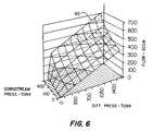
- FIG. 6is a diagram similar to FIG. 4 showing the characteristics of another type of flow restrictor as a function of differential pressure across and pressure downstream of the flow restrictor;
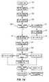
- FIGS. 7A and 7Bare flow charts of certain steps carried out in the operation of the fluid mass flow controller shown in FIGS. 1 and 2.
- the mass flow controller 20includes a two-part modular body 22 comprising generally rectangular block shaped body parts 24 and 26 which may be suitably joined to each other by conventional mechanical fasteners 28 at cooperating planar faces 24 a and 26 a , respectively.
- the body parts 24 and 26are provided with suitable fluid conductor connector portions 25 and 27 to provide for connecting the fluid mass flow controller to conduits for a system for supplying, in particular, toxic or reactive fluids in gaseous form for use in semiconductor fabrication, for example.
- the mass flow controller 20may be interposed in a fabrication system including a source pressure vessel 28 for pressure fluid such as tungsten hexafluoride, chlorine, or sulfur hexafluoride, for example.
- Source pressure vessel 28is connected to the flow controller 20 via a suitable conduit 30 and a purge conduit 32 is also connected to conduit 30 and to a source of purge gas, not shown, for purging the flow controller to a suitable receiver or scrubber 34 , when needed.
- a precise flow of fluidis controlled for entry into a semiconductor fabrication chamber or vessel 36 via conduit 33 .
- Chamber 36is typically maintained at a substantially reduced pressure by way of one or more vacuum pumps 37 , for example.
- the system in which the flow controller 20 is interposed, as shown in FIG. 2,is shown by way of example in simplified form to illustrate one preferred application of the flow controller.
- the body part 24supports an electrically controlled flow control valve 40 which is removably mounted on a face 24 b of body part 24 by conventional mechanical fasteners, not shown.
- Valve 40includes an electrically actuated closure member 41 operable to throttle flow of fluid from an internal passage 42 of body part 24 to a second internal passage 44 of body part 24 .
- Valve 40also includes an actuator 43 for the closure member 41 .
- Actuator 43is preferably of a type using a solenoid or piezoelectric material for rapid response and fineness of control of closure member 41 .
- a first pressure transducer 46is also removably mounted on body part 24 and is in communication with a passage 47 in body part 24 which is in communication with passage 44 .
- a second pressure transducer 48is removably mounted on body part 26 and is in communication with a passage 49 which opens into a longitudinal passage 50 in body part 26 , which passage is also connected to conduit 33 leading to the fabrication chamber 36 .
- Pressure transducers 46 and 48may be of a type commercially available from Honeywell Data Instruments Division, for example. Control valve 40 and pressure transducers 46 and 48 may be disposed within a removable cover 51 , FIG. 1, for the flow controller 20 .
- the body part 24includes a cylindrical counterbore 54 formed therein and concentric with the passage 44 for receiving a flow restrictor 56 .
- Flow restrictor 56is supported in a tubular sleeve 58 which may be mounted in a suitable tubular adapter 60 supported in the counterbore 54 between seal rings 62 . Accordingly, the flow restrictor 56 may be easily removed from the body 22 by separating the body parts 24 and 26 , removing the flow restrictor together with its support sleeve 58 and replacing the flow restrictor with a suitable replacement restrictor of the same flow characteristics or a selected other flow characteristic.
- the flow restrictor 56preferably comprises a sintered metal cylindrical plug shaped member having a predetermined porosity for allowing fluid to flow therethrough by providing restriction to flow sufficient to create a differential pressure thereacross which may be sensed by the pressure transducers 46 and 48 .
- Flow restrictor 56may, for example, be fabricated of stainless steel or nickel particles suitably compressed and sintered to provide the desired porosity and flow restriction characteristic.
- Flow restrictor 56is advantageously disposed in flow controller 20 downstream of control valve 40 .
- the flow controller 20is adapted to be operated by a control circuit or system including a microcontroller characterized as a digital signal processor 70 which is operably connected to a non-volatile memory, such as an EEPROM 72 , a power supply 74 and a suitable valve driver circuit 76 .
- the microcontroller 70is operably connected to the valve 40 for effecting movement of the closure member 41 by way of the driver 76 .
- the microcontroller 70is also operably connected to the pressure transducers 46 and 48 and to a temperature sensor 78 which may be located to sense the temperature of fluid flowing through the controller 20 at a predetermined location.
- the microcontroller 70is also operably connected to a suitable interface 80 for receiving command signals, data sets and programming changes from various sources.
- the microcontroller 70is preferably a TMS320 LF2407 fixed point microcontroller available from Texas Instruments Incorporated.
- the pressure sensors 46 and 48operate in a plus/minus 0.5 volt range with fourteen to sixteen bit resolution as analog inputs to the microcontroller 70 which carries its own A/D and D/A converters. Other analog inputs will be for the temperature sensor 78 and a zero to five volt set point command signal input with twelve bit resolution.
- the microcontroller 70also provides analog output signals for controlling operation of the valve 40 via the driver 76 . Communication with the microcontroller 70 may be via an RS485 4-wire communication link and/or a CAN (Controller Area Network).
- the microcontroller 70is also capable of supporting a JTAG interface for emulation and debug and a powerup bootloader function for programming.
- the memory 72is preferably a serial EEPROM of at least four thousand bytes.
- the microcontroller 70requires a closed loop control function to be executed at a rate of about one hundred times per second between the inputs for the pressure sensors 46 and 48 and the output signal for controlling the valve 40 .
- Communication through interface 80is carried out while the control loop is functioning although new data transfer or transfer to the memory 72 may be supplied when control loop updates are not being maintained.
- FIG. 4shows a typical characteristic of flow in standard cubic centimeters per minute (SCCM) as a function of the differential pressure (torr) across the flow restrictor 56 and also as a function of the downstream pressure (torr) in the passage 50 , conduit 33 and fabrication chamber 36 .
- SCCMstandard cubic centimeters per minute
- the diagram of FIG. 4indicates that the flow characteristics of a fluid flowing across a restrictor, in the pressure ranges indicated in the diagram, may be in accordance with a three-dimensional surface indicated by numeral 90 .
- the flow characteristic or surface 90is for a particular temperature.
- the mass flow characteristic 90 for the fluid testedwas conducted at 25° C.
- measurements taken at lower temperatureswould provide flow characteristics indicated by the surfaces 92 and 94 , for example.
- the flow characteristic indicated by surface 92is for a temperature lower than the temperature for the flow characteristic indicated by surface 90 and the flow characteristic which is determined by the surface 94 is at a temperature lower than the measurements taken for developing the flow characteristic surface 92 .
- a mass flow rate across a flow restrictorvaries with the downstream pressure. For example, if the downstream pressure is approximately 0.0 torr and the pressure differential across the flow restrictor is approximately 1575.0 torr, the flow rate for the particular restrictor tested is about 280 SCCM. However, if the downstream pressure is 760.0 torr (standard atmospheric pressure), the flow rate for the same pressure differential across the flow restrictor is approximately 500 SCCM. Accordingly, the behavior of fluids flowing across a flow restrictor, particularly in gaseous form, is dependent not only on temperature and differential pressure but also the pressure downstream of the flow restrictor.
- the flow characteristics indicated in FIG. 4 at various temperatures, differential pressures across the flow restrictor and downstream pressuresare for a sintered metal type flow restrictor, such as the flow restrictor 56 .
- a similar flow characteristicis indicated for a sharp edged circular orifice at 25° C. and is indicated by numeral 95 .
- the specific flow characteristics shown in FIGS. 4 and 6are for nitrogen gas although other gases are indicated to behave in accordance with the general flow characteristics shown in FIGS. 4 and 6 for the types of flow restrictors described herein.
- a flow characteristic in accordance with the diagrams of FIGS. 4 and 6may be developed for particular types of flow restrictors used in connection with a mass flow controller, such as the controller 20 , and for various fluids in liquid and gaseous form, including the process gases or vapors used in semiconductor fabrication.
- Data points representing the three-dimensional flow characteristicsmay be developed in various ways and entered into the memory 72 of the flow controller 20 .
- the flow controller microcontroller 70when operated in a set point mode can be programmed to command operation of the valve 40 to adjust the flow through the flow controller 20 to approach the setpoint by sensing the pressure differential across the flow restrictor by the pressure transducers 46 and 48 to determine the actual flow rate, repeatedly, until the flow rate is essentially that programmed into the microcontroller 70 as the setpoint or pursuant to instructions input to the microcontroller.
- the data points representing the surfaces 90 , 92 94 for a particular gasmay be obtained using conventional flow measuring equipment.
- a rate of change mass flow measuring apparatusmay also be used to obtain the data points. Moreover, such a flow measuring apparatus may be used to verify the operation of a flow controller, such as the flow controller 20 within its design specification, and such apparatus may also be used to verify whether or not a particular flow restrictor is within its design specification. Once a design specification has been established for a flow restrictor and a flow controller of the types described herein, the performance of each may be verified by a rate of change mass flow measuring apparatus or other mass flow measuring apparatus or devices and use of an inert gas so that toxic and highly reactive gases are not required to be used during verification tests on the complete flow controller or on a flow restrictor, respectively.
- a selected number of data pointsmay be verified at flow rates of 50, 100, 500 and 3,000 SCCM at 30 psig inlet pressure, with exhaust pressure being atmospheric, for a flow controller, such as the controller 20 , or for a flow restrictor, such as flow restrictor 56 .
- Data points representing the design specification of the flow controller 20may also be entered into the memory 72 to verify the operability of the flow controller when tested with the aforementioned rate of change flow measuring apparatus.
- a suitable rate of change or so-called rate of rise mass flow measuring apparatusis commercially available.
- the fluid mass flow controller 20may also be connected via its interface 80 with a network adapted to be connected to a source of data for any fluid which has been tested in conjunction with a controller of the same type as the flow controller 20 .
- any gas to be controlled by the flow controller 20may have its flow characteristics entered into the memory 72 by merely querying a database stored in a suitable processor.
- a vendor of the flow controller 20may have selected data sets stored on a suitable processor and memory associated therewith for a wide variety of gases, each data set corresponding substantially to the type of data sets that would provide the flow characteristics shown in FIGS. 4 and 6 for any one type of flow restrictor, respectively.
- An authorized customer using a flow controller, such as the flow controller 20 , and desiring to begin using the controller with a particular gaswould merely make an inquiry to the vendor source and download the needed data set directly to the microcontroller 70 and its memory 72 via a network such as the Internet, for example.
- the microcontroller or processor 70is operable to execute closed loop control and communication functions. Closed loop control is preferably executed at a rate of 100 times per second and requires execution of lookup tables or polynomial calculations. All code may be written in “C”.
- the functions of the microcontroller or processor 70are summarized in the flow diagram of FIG. 7 A. Step 100 in FIG. 7A indicates a 10 millisecond interrupt to drive the key functions of the processor 70 . In step 102 , the processor obtains 64 samples of downstream pressure XD 1 and averages the samples.
- step 104the processor 70 obtains 64 samples of the upstream pressure XD 2 and averages the samples.
- Step 106is an averaging of 32 samples of an analog output signal for control of the valve 40 identified by the software tag CV 1 SN.
- Step 108indicates operation of the processor 70 in the signal mode to obtain 32 samples of a zero to five volt setpoint command signal input in step 110 , and a 32 sample zero to five volt analog output signal in step 112 .
- Step 114indicates when analog inputs are shorted to ground.
- Step 116indicates the processor obtaining 32 samples of the signal from temperature sensor 78 , indicated as TE 1 , and averaging such samples.
- Step 118provides for converting the signal inputs to English units of pressure, flow and temperature.
- Step 120 in FIG. 7Ais the execution of a calculation of flow routine using, for example, the surfaces 90 , 92 and 94 of FIG. 4 .
- New processorproceeds to the control mode at step 122 .
- FIG. 7Billustrates how the calculation of flow routine is carried out using sets of so-called three dimensional maps, such as the surfaces 90 , 92 and 94 , for example, for respective operating temperatures and whereby the flow is calculated as a function of the variables of differential pressure across the flow restrictor 56 , the downstream pressure in the flow passage 50 and the temperature sensed by the sensor 78 .
- a set of flowruns over a range of downstream pressures and flow rates is obtained for the flow restrictor 56 .
- This data setis fitted to an array of three dimensional curves.
- the so-called mapcan be thought of as flow on the z axis mapped to differential pressure, XD 2 ⁇ XD 1 , on the x axis and discharge or downstream pressure, XD 1 on the y axis.
- the best-fit processgenerates curves at various values of y. Typically curves of x versus z might be generated for XD 1 being equal to 1, 50, 100, 300, 500 and 700 torr, for example. Then the process is repeated at another operating temperature. The calibration data is then mapped from floating point numbers to the fixed point quantities that are used in the processor. These tables are download to the processor and are called during the flow calculations.
- the get calibration data of step 124FIG. 7B, is carried out by obtaining the calibration maps or surfaces at the nearest temperature above and below the temperature sensed by sensor 78 . At steps 126 and 128 , flow is calculated by interpolating the differential pressure XD 2 ⁇ XD 1 for two curves in the calibration data (CAL DATA).
- Flow at the current calibration temperatureis calculated by interpolating between calibration flow data points.
- flow at the current CAL DATA temperatureis calculated by interpolating between Flow( 0 ) and Flow(i) by the value of XD 1 and the y axis values for Flow( 0 ) and Flow( 1 ).
- Flowis calculated by interpolating between the Flow@Temp( 0 ) and Flow@Temp( 1 ) by the value of TE 1 and the temperatures for the two CAL DATA sets selected.
- the flow restrictor 56may be adapted for operation in conjunction with other flow controllers and related devices.
- the flow restrictor 56may, for example, be removably mounted in a conventional fitting, such as a face seal union fitting 110 .
- the fitting 110includes a longitudinal through passage 112 which is counterbored at one end to provide a bore 114 for receiving the cylindrical plug flow restrictor 56 and its tubular support sleeve 58 .
- the sleeve 58may be a light press fit in the bore 114 .
- a flow restrictor for use in conjunction with the flow controller 20may be characterized as a cylindrical plug having a diameter of approximately 0.18 inches and a length of approximately 0.18 inches and may be formed of porous sintered stainless steel, nickel or Hastelloy C-22.
- the solid steel sleeve 58may be formed of 316L stainless steel. It is contemplated that the manufacturing tolerances of the flow restrictor 56 may be such as to require only verification of the performance characteristics of the restrictor by verifying the mass flow rates of, for example, 50, 100, 500 and 3,000 SCCM at a pressure upstream of the restrictor of 30 psig with exhaust to atmosphere.
- the flow controller 20 and/or the flow restrictor 56may be verified as to its operability by flowing predetermined quantities of an inert gas through these devices using the aforementioned rate of change flow measuring apparatus or a similar apparatus to verify performance.
- the flow restrictor and/or the flow controllermay then be placed in or returned to service with assurance that the respective devices will perform in accordance with a flow characteristic, such as that indicated in FIG. 4, for example.
- the mass flow controller 20 and the flow restrictor 56are constructed and operated as a flowmeter and may be used as a flowmeter as well as for controlling fluid flow rate to a setpoint condition.
Landscapes
- Physics & Mathematics (AREA)
- General Physics & Mathematics (AREA)
- Engineering & Computer Science (AREA)
- Automation & Control Theory (AREA)
- Flow Control (AREA)
- Electrical Discharge Machining, Electrochemical Machining, And Combined Machining (AREA)
Abstract
Description
Claims (32)
Priority Applications (12)
| Application Number | Priority Date | Filing Date | Title |
|---|---|---|---|
| US09/666,039US6539968B1 (en) | 2000-09-20 | 2000-09-20 | Fluid flow controller and method of operation |
| JP2002529328AJP4921684B2 (en) | 2000-09-20 | 2001-09-14 | Fluid mass flow controller and operation method thereof |
| PCT/US2001/028665WO2002025391A1 (en) | 2000-09-20 | 2001-09-14 | Fluid flow controller and method of operation |
| CNB018159877ACN100385359C (en) | 2000-09-20 | 2001-09-14 | Fluid mass flow controller and fluid flow meter and measuring and controlling method |
| AU2001292651AAU2001292651A1 (en) | 2000-09-20 | 2001-09-14 | Fluid flow controller and method of operation |
| EP01973028AEP1328854B1 (en) | 2000-09-20 | 2001-09-14 | Fluid flow controller and method of operation |
| DE60139135TDE60139135D1 (en) | 2000-09-20 | 2001-09-14 | FLUID FLOW CONTROL AND OPERATING PROCEDURES |
| KR1020077027614AKR100875813B1 (en) | 2000-09-20 | 2001-09-14 | Fluid Mass Flow Controller and Its Operation Method |
| AT01973028TATE435448T1 (en) | 2000-09-20 | 2001-09-14 | FLUID FLOW CONTROL AND METHOD OF OPERATION |
| KR1020037003975AKR100875775B1 (en) | 2000-09-20 | 2001-09-14 | Fluid Mass Flow Controller and Its Operation Method |
| MYPI20014379AMY128274A (en) | 2000-09-20 | 2001-09-19 | Fluid flow controller and method of operation |
| TW090123230ATW505837B (en) | 2000-09-20 | 2001-09-20 | Fluid flow controller and method of operation |
Applications Claiming Priority (1)
| Application Number | Priority Date | Filing Date | Title |
|---|---|---|---|
| US09/666,039US6539968B1 (en) | 2000-09-20 | 2000-09-20 | Fluid flow controller and method of operation |
Publications (1)
| Publication Number | Publication Date |
|---|---|
| US6539968B1true US6539968B1 (en) | 2003-04-01 |
Family
ID=24672579
Family Applications (1)
| Application Number | Title | Priority Date | Filing Date |
|---|---|---|---|
| US09/666,039Expired - LifetimeUS6539968B1 (en) | 2000-09-20 | 2000-09-20 | Fluid flow controller and method of operation |
Country Status (11)
| Country | Link |
|---|---|
| US (1) | US6539968B1 (en) |
| EP (1) | EP1328854B1 (en) |
| JP (1) | JP4921684B2 (en) |
| KR (2) | KR100875775B1 (en) |
| CN (1) | CN100385359C (en) |
| AT (1) | ATE435448T1 (en) |
| AU (1) | AU2001292651A1 (en) |
| DE (1) | DE60139135D1 (en) |
| MY (1) | MY128274A (en) |
| TW (1) | TW505837B (en) |
| WO (1) | WO2002025391A1 (en) |
Cited By (101)
| Publication number | Priority date | Publication date | Assignee | Title |
|---|---|---|---|---|
| US20030212507A1 (en)* | 2002-05-13 | 2003-11-13 | Taiwan Semiconductor Manufacturing Co., Ltd. | Real time mass flow control system with interlock |
| US20030234044A1 (en)* | 2002-06-24 | 2003-12-25 | Ali Shajii | Apparatus and method for mass flow controller with a plurality of closed loop control code sets |
| US20030236638A1 (en)* | 2002-06-24 | 2003-12-25 | Ali Shajii | Apparatus and method for displaying mass flow controller pressure |
| US20030236643A1 (en)* | 2002-06-24 | 2003-12-25 | Ali Shajii | Apparatus and method for calibration of mass flow controller |
| US20030234048A1 (en)* | 2002-06-24 | 2003-12-25 | Ali Shajii | Apparatus and method for mass flow controller with embedded web server |
| US20030234045A1 (en)* | 2002-06-24 | 2003-12-25 | Ali Shajii | Apparatus and method for mass flow controller with on-line diagnostics |
| US20030234046A1 (en)* | 2002-06-24 | 2003-12-25 | Ali Shajii | Apparatus and method for self-calibration of mass flow controller |
| US20030234047A1 (en)* | 2002-06-24 | 2003-12-25 | Ali Shajii | Apparatus and method for dual processor mass flow controller |
| WO2004001516A1 (en)* | 2002-06-24 | 2003-12-31 | Mks Instruments, Inc. | Apparatus and method for pressure fluctuation insensitive mass flow control |
| US20040069348A1 (en)* | 2002-06-28 | 2004-04-15 | Jacobs Steven D. | Valve calibration method and apparatus |
| WO2004010474A3 (en)* | 2002-07-19 | 2004-05-06 | Mykrolis Corp | Liquid flow controller and precision dispense apparatus and system |
| US20040083807A1 (en)* | 2002-08-28 | 2004-05-06 | Mudd Daniel T. | Higher accuracy pressure based flow controller |
| US20040173017A1 (en)* | 2001-04-23 | 2004-09-09 | O'brien Vincent T. | Fluid properties evaluation |
| US20040204794A1 (en)* | 2001-12-28 | 2004-10-14 | Tadahiro Ohmi | Advance pressure type flow control device |
| US6810308B2 (en) | 2002-06-24 | 2004-10-26 | Mks Instruments, Inc. | Apparatus and method for mass flow controller with network access to diagnostics |
| US20040238040A1 (en)* | 2003-05-28 | 2004-12-02 | Shimadzu Corporation | Gas chromatograph |
| WO2005001910A1 (en)* | 2003-06-27 | 2005-01-06 | Hyundai Calibration & Certification Technologies Co., Ltd | Apparatus for controlling flow rate of gases used in semiconductor device by differential pressure |
| WO2005001911A1 (en)* | 2003-06-27 | 2005-01-06 | Hyundai Calibration & Certification Technologies Co., Ltd | Apparatus for controlling flow rate of gases used in semiconductor device by differencial pressure |
| US20050288825A1 (en)* | 2004-07-08 | 2005-12-29 | Tinsley Kenneth E | Method and system for a mass flow controller with reduced pressure sensitivity |
| US20060005882A1 (en)* | 2004-07-09 | 2006-01-12 | Tison Stuart A | Method and system for flow measurement and validation of a mass flow controller |
| US20060081288A1 (en)* | 2004-10-07 | 2006-04-20 | Eaton Corporation | Closed loop pressure control system and electrically operated pressure control valve with integral pressure sensor and method of making same |
| US20060112773A1 (en)* | 2004-12-01 | 2006-06-01 | Rosemount Inc. | Process fluid flow device with variable orifice |
| US20060123921A1 (en)* | 2004-12-15 | 2006-06-15 | Tison Stuart A | System and method for measuring flow |
| US20060157133A1 (en)* | 2005-01-14 | 2006-07-20 | Kurtz Anthony D | Combustion transducer apparatus employing pressure restriction means |
| WO2006017116A3 (en)* | 2004-07-09 | 2007-03-01 | Celerity Inc | Method and system for flow measurement and validation of a mass flow controller |
| US7201066B1 (en)* | 2005-03-30 | 2007-04-10 | The Board Of Regents For Oklahoma State University | System for automatic tire inflation |
| US20070256739A1 (en)* | 2006-05-02 | 2007-11-08 | Thermojet Do Brasil Ltda. | Single system for low or high pressure gases control and high or low pressure gases control valve |
| US20070290382A1 (en)* | 2006-06-14 | 2007-12-20 | Marc Laverdiere | Systems and methods for managing heat transfer in a fluid handling device |
| US20080029174A1 (en)* | 2004-08-31 | 2008-02-07 | Asahi Organic Chemicals Industry Co., Ltd. | Fluid Control Device |
| US20080091306A1 (en)* | 2002-06-24 | 2008-04-17 | Mks Instruments, Inc. | Apparatus and method for pressure fluctuation insensitive mass flow control |
| US20080198896A1 (en)* | 2006-07-19 | 2008-08-21 | Nair Rajesh M | Airflow sensor for filter blockage detection |
| US7424346B2 (en) | 2002-06-24 | 2008-09-09 | Mks Instruments, Inc. | Apparatus and method for pressure fluctuation insensitive mass flow control |
| US20080294293A1 (en)* | 2004-08-31 | 2008-11-27 | Asahi Organic Chemicals Industry Co., Ltd. | Fluid Controller |
| US20090101217A1 (en)* | 2005-07-27 | 2009-04-23 | Surpass Industry Co., Ltd. | Flow-Rate Controller, and Regulator Unit and Valve Unit Used for the Same |
| US20090164050A1 (en)* | 2007-12-21 | 2009-06-25 | Rosemount, Inc. | Diagnostics for mass flow control |
| US20090171507A1 (en)* | 2005-08-26 | 2009-07-02 | Fujikin Incorporated | Gasket type orifice and pressure type flow rate control apparatus for which the orifice is employed |
| US20100005904A1 (en)* | 2008-07-08 | 2010-01-14 | Surpass Industry Co., Ltd. | Differential-pressure flow meter and flow-rate controller |
| US20100139775A1 (en)* | 2005-06-27 | 2010-06-10 | Fujikin Incorporated | Flow rate range variable type flow rate control apparatus |
| US20100193051A1 (en)* | 2009-02-05 | 2010-08-05 | Hiroki Igarashi | Differential-pressure flowmeter and flow-rate controller |
| US7875109B1 (en)* | 2007-03-08 | 2011-01-25 | A+ Manufacturing, Llc | Integral flow restrictor valve |
| US7896045B2 (en) | 2006-11-13 | 2011-03-01 | The Board Of Regents For Oklahoma State University | Apparatus for delivering air through powered axle assemblies |
| CN102251893A (en)* | 2010-05-17 | 2011-11-23 | 迈瑞医疗(瑞典)公司 | High pressure valve and control method |
| US20110284779A1 (en)* | 2010-05-18 | 2011-11-24 | Mindray Medical Sweden Ab | Method and apparatus for controlling a high-pressure valve |
| US20120180876A1 (en)* | 2009-10-01 | 2012-07-19 | Horiba Stec, Co., Ltd. | Flow rate measuring mechanism, mass flow controller, and pressure sensor |
| CN101568375B (en)* | 2006-11-13 | 2012-10-10 | 东京毅力科创株式会社 | Method for supplying treatment gas, treatment gas supply system |
| US20140069527A1 (en)* | 2012-09-10 | 2014-03-13 | Daniel T. Mudd | Pressure based mass flow controller |
| USRE44943E1 (en)* | 2001-04-23 | 2014-06-10 | Commonwealth Scientific And Industrial Research Organisation | Fluid properties evaluation |
| US20140182692A1 (en)* | 2011-05-10 | 2014-07-03 | Fujikin Incorporated | Pressure type flow control system with flow monitoring |
| US20140230915A1 (en)* | 2013-02-15 | 2014-08-21 | Daniel T. Mudd | Gas delivery system for outputting fast square waves of process gas during semiconductor processing |
| US20150233746A1 (en)* | 2014-02-20 | 2015-08-20 | Surpass Industry Co., Ltd. | Differential pressure type flowmeter and flow controller provided with the same |
| US20150277447A1 (en)* | 2014-03-28 | 2015-10-01 | Bray International, Inc. | Pressure Independent Control Valve for Small Diameter Flow, Energy Use and/or Transfer |
| US9188989B1 (en)* | 2011-08-20 | 2015-11-17 | Daniel T. Mudd | Flow node to deliver process gas using a remote pressure measurement device |
| US9285079B2 (en)* | 2011-07-28 | 2016-03-15 | Horiba Stec, Co., Ltd. | Gas supply system |
| US9383758B2 (en) | 2005-06-27 | 2016-07-05 | Fujikin Incorporated | Flow rate range variable type flow rate control apparatus |
| US20160299514A1 (en)* | 2015-04-08 | 2016-10-13 | Tokyo Electron Limited | Gas supply control method |
| US9523435B2 (en) | 2009-10-15 | 2016-12-20 | Pivotal Systems Corporation | Method and apparatus for gas flow control |
| US20170010625A1 (en)* | 2015-07-10 | 2017-01-12 | Pivotal Systems Corporation | Method and apparatus for gas flow control |
| US9556518B2 (en) | 2011-07-08 | 2017-01-31 | Fujikin Incorporated | Raw material gas supply apparatus for semiconductor manufacturing equipment |
| EP3150975A1 (en)* | 2015-10-02 | 2017-04-05 | Surpass Industry Co., Ltd. | Flow rate adjustment apparatus |
| US9631777B2 (en) | 2011-09-06 | 2017-04-25 | Fujikin Incorporated | Raw material vaporizing and supplying apparatus equipped with raw material concentration |
| US20170153652A1 (en)* | 2017-02-13 | 2017-06-01 | Robert M. McMillan | Reconfigurable modular fluid flow control system for liquids or gases |
| US9717455B2 (en)* | 2015-03-31 | 2017-08-01 | Empire Technology Development Llc | Portable flow meter for low volume applications |
| US9739378B2 (en) | 2014-04-17 | 2017-08-22 | Vistadeltek, Llc | Ultra-seal gasket for joining high purity fluid pathways |
| US9857805B2 (en)* | 2013-02-18 | 2018-01-02 | Flo Technologies, Inc. | Fluid monitoring and control system |
| US9921089B2 (en) | 2005-06-27 | 2018-03-20 | Fujikin Incorporated | Flow rate range variable type flow rate control apparatus |
| US9958302B2 (en) | 2011-08-20 | 2018-05-01 | Reno Technologies, Inc. | Flow control system, method, and apparatus |
| US9976887B1 (en)* | 2011-06-22 | 2018-05-22 | Daniel T. Mudd | Wider dynamic accuracy range for gas delivery devices |
| US9980672B2 (en) | 2015-07-16 | 2018-05-29 | Empire Technology Development Llc | Single-chambered sweat rate monitoring sensor |
| US10054959B2 (en) | 2013-03-15 | 2018-08-21 | Bhushan Somani | Real time diagnostics for flow controller systems and methods |
| US20190085988A1 (en)* | 2016-02-29 | 2019-03-21 | Fujikin Incorporated | Flow rate control device |
| US10303189B2 (en) | 2016-06-30 | 2019-05-28 | Reno Technologies, Inc. | Flow control system, method, and apparatus |
| US10410501B2 (en) | 2007-10-24 | 2019-09-10 | Michael Edward Klicpera | Water meter and leak detection system |
| US10527516B2 (en) | 2017-11-20 | 2020-01-07 | Phyn Llc | Passive leak detection for building water supply |
| US10663337B2 (en) | 2016-12-30 | 2020-05-26 | Ichor Systems, Inc. | Apparatus for controlling flow and method of calibrating same |
| US10679880B2 (en) | 2016-09-27 | 2020-06-09 | Ichor Systems, Inc. | Method of achieving improved transient response in apparatus for controlling flow and system for accomplishing same |
| US10774796B2 (en) | 2016-04-11 | 2020-09-15 | Perkins Engines Company Limited | EGR valve with integrated sensor |
| US10838437B2 (en) | 2018-02-22 | 2020-11-17 | Ichor Systems, Inc. | Apparatus for splitting flow of process gas and method of operating same |
| US10883865B2 (en) | 2018-09-19 | 2021-01-05 | Swagelok Company | Flow restricting fluid component |
| US10890474B2 (en) | 2018-09-18 | 2021-01-12 | Swagelok Company | Fluid monitoring module arrangements |
| US10962993B2 (en) | 2013-02-18 | 2021-03-30 | Flo Technologies, Inc. | Manual control for actuated fluid monitoring and control device |
| US10983538B2 (en) | 2017-02-27 | 2021-04-20 | Flow Devices And Systems Inc. | Systems and methods for flow sensor back pressure adjustment for mass flow controller |
| US11095960B2 (en) | 2018-03-07 | 2021-08-17 | Michael Edward Klicpera | Water meter and leak detection system having communication with a intelligent central hub listening and speaking apparatus, wireless thermostat and/or home automation system |
| US11105512B2 (en) | 2018-03-30 | 2021-08-31 | Midea Group Co., Ltd | Method and system for controlling a flow curve of an electromechanical gas valve |
| US11144075B2 (en) | 2016-06-30 | 2021-10-12 | Ichor Systems, Inc. | Flow control system, method, and apparatus |
| US11237574B2 (en) | 2013-02-18 | 2022-02-01 | Flo Technologies, Inc. | Fluid monitoring and control system |
| US11262069B2 (en) | 2020-06-25 | 2022-03-01 | Midea Group Co., Ltd. | Method and system for auto-adjusting an active range of a gas cooking appliance |
| US11280651B2 (en) | 2019-03-25 | 2022-03-22 | Flo Technologies, Inc. | Thin film thermal mass flow sensor in fluid applications |
| US20220197316A1 (en)* | 2019-04-25 | 2022-06-23 | Fujikin Incorporated | Flow rate control device |
| US20220199431A1 (en)* | 2019-04-15 | 2022-06-23 | Lam Research Corporation | Modular-component system for gas delivery |
| US11512993B2 (en)* | 2017-09-25 | 2022-11-29 | Fujikin Incorporated | Valve device, adjustment information generating method, flow rate adjusting method, fluid control system, flow rate control method, semiconductor manufacturing system and semiconductor manufacturing method |
| US11549837B2 (en) | 2016-02-04 | 2023-01-10 | Michael Edward Klicpera | Water meter and leak detection system |
| US20230011244A1 (en)* | 2019-12-25 | 2023-01-12 | Fujikin Incorporated | Pressure control device |
| US11585444B2 (en)* | 2019-08-05 | 2023-02-21 | Ichor Systems, Inc. | Seal for a flow restrictor |
| US11624636B2 (en) | 2019-05-07 | 2023-04-11 | Fortune Brands Water Innovations LLC | Turbine design for flow meter |
| US20230175608A1 (en)* | 2021-12-03 | 2023-06-08 | Goodrich Corporation | Smart pressure regulator for emergency evacuation inflation system |
| US11841036B2 (en) | 2019-08-05 | 2023-12-12 | Ichor Systems, Inc. | Laminar flow restrictor and seal for same |
| US11899477B2 (en) | 2021-03-03 | 2024-02-13 | Ichor Systems, Inc. | Fluid flow control system comprising a manifold assembly |
| US12000723B2 (en) | 2022-02-18 | 2024-06-04 | Mks Instruments, Inc. | Method and apparatus for pressure based mass flow control |
| US12029172B1 (en) | 2023-01-07 | 2024-07-09 | Lumo, Inc. | Water control device for agriculture |
| US12405184B1 (en) | 2023-11-22 | 2025-09-02 | Michael Edward Klicpera | Water meter and leak detection system |
| US12436049B2 (en) | 2023-02-16 | 2025-10-07 | Te Connectivity Solutions Gmbh | Sensor die with a diaphragm |
Families Citing this family (28)
| Publication number | Priority date | Publication date | Assignee | Title |
|---|---|---|---|---|
| US6152162A (en) | 1998-10-08 | 2000-11-28 | Mott Metallurgical Corporation | Fluid flow controlling |
| US6886929B2 (en) | 2002-10-25 | 2005-05-03 | Hewlett-Packard Development Company, L.P. | Techniques for improving pressure sensor shock robustness in fluid containment devices |
| US6955072B2 (en)* | 2003-06-25 | 2005-10-18 | Mks Instruments, Inc. | System and method for in-situ flow verification and calibration |
| CN1974025B (en)* | 2004-10-28 | 2010-06-23 | 博奥生物有限公司 | Micro liquid jetting system |
| CN1311913C (en)* | 2004-10-28 | 2007-04-25 | 博奥生物有限公司 | A micro-liquid injection system |
| US7468095B2 (en)* | 2005-05-12 | 2008-12-23 | Perkinelmer Las, Inc. | System for controlling flow into chromatographic column using transfer line impedance |
| US7287432B2 (en)* | 2005-11-17 | 2007-10-30 | Rosemount Inc. | Process transmitter with overpressure vent |
| CN100444310C (en)* | 2005-12-07 | 2008-12-17 | 北京北方微电子基地设备工艺研究中心有限责任公司 | Mass flow controller on-line correction method |
| EP2047154B1 (en)* | 2006-08-02 | 2013-06-12 | BorgWarner, Inc. | Egr system and egr valve with integrated pressure sensor |
| US8006571B2 (en)* | 2007-09-19 | 2011-08-30 | Siemens Industry, Inc. | Air flow measurement |
| US9288886B2 (en)* | 2008-05-30 | 2016-03-15 | Colorado State University Research Foundation | Plasma-based chemical source device and method of use thereof |
| WO2011040409A1 (en)* | 2009-10-01 | 2011-04-07 | 株式会社堀場エステック | Flow rate measuring mechanism and mass flow controller |
| US8632512B2 (en)* | 2010-04-09 | 2014-01-21 | Kci Licensing, Inc. | Apparatuses, methods, and compositions for the treatment and prophylaxis of chronic wounds |
| US11022985B2 (en) | 2011-12-16 | 2021-06-01 | Fluid Handling Llc | Discrete valve flow rate converter |
| CN102873007A (en)* | 2012-09-18 | 2013-01-16 | 张家港市盛港绿色防火建材有限公司 | Material feeding device used for plate making machine |
| CN102873747A (en)* | 2012-09-18 | 2013-01-16 | 张家港市盛港绿色防火建材有限公司 | Discharging control device for plate maker |
| CN102984928B (en)* | 2012-12-31 | 2015-11-11 | 西安飞豹科技发展公司 | Airborne small-scale liquid device for cooling |
| KR101455928B1 (en)* | 2013-04-05 | 2014-10-31 | 배정이 | Mass flow controller with motor driving circuit |
| CN104678985B (en)* | 2013-12-03 | 2018-10-09 | 无锡华润华晶微电子有限公司 | A kind of device and method of verification mass flow controller |
| CN103859574B (en)* | 2014-03-31 | 2016-02-10 | 西南大学 | A kind of tobacco flue-curing house |
| EP3234723B1 (en)* | 2014-12-15 | 2022-03-23 | Fluid Handling LLC. | A discrete valve flow rate converter |
| CN105333207B (en)* | 2015-12-11 | 2018-08-24 | 中国航空工业集团公司西安飞机设计研究所 | A kind of bleed valve based on flow-rate adjustment |
| KR102079988B1 (en)* | 2016-04-28 | 2020-02-21 | 가부시키가이샤 후지킨 | Fluid control device, control method of fluid control device, and fluid control system |
| WO2018047644A1 (en)* | 2016-09-12 | 2018-03-15 | 株式会社堀場エステック | Flow ratio control device, program for flow ratio control device, and flow ratio control method |
| TWI723489B (en)* | 2019-08-12 | 2021-04-01 | 鐳鋌科技有限公司 | Gas scrubber energy-saving control device |
| CN110500443B (en)* | 2019-08-26 | 2020-11-06 | 赵国栋 | Proportional pressure reducing valve capable of monitoring fluid speed before and after valve |
| US12181328B2 (en)* | 2020-04-17 | 2024-12-31 | Illinois Tool Works Inc. | Flow through pressure sensor structured to remove dead volume |
| US20240281007A1 (en)* | 2023-02-17 | 2024-08-22 | Mks Instruments, Inc. | Method and Apparatus for Integrated Pressure and Flow Controller |
Citations (77)
| Publication number | Priority date | Publication date | Assignee | Title |
|---|---|---|---|---|
| US2666297A (en) | 1950-03-14 | 1954-01-19 | Elmer C Skousgaard | Container and discharge valve therefor |
| US3271994A (en) | 1965-04-19 | 1966-09-13 | Jered Ind Inc | Fluid flow comparator for use in calibrating fluid flow orifices |
| US3335748A (en) | 1964-09-15 | 1967-08-15 | Henry B Peter | Adjustable control for metered flow |
| US3559482A (en) | 1968-11-27 | 1971-02-02 | Teledyne Inc | Fluid flow measuring apparatus |
| US3570807A (en) | 1969-01-14 | 1971-03-16 | Bell Aerospace Corp | Electromechanical control valve |
| US3807456A (en) | 1970-06-25 | 1974-04-30 | Trw Inc | Hydraulic controller including rotary valve |
| US3814541A (en) | 1971-11-24 | 1974-06-04 | Delta Controls Ltd | Fluid supply apparatus |
| US3841520A (en) | 1969-04-04 | 1974-10-15 | Airco Inc | Flame arresting vent valve |
| US3910113A (en) | 1972-11-20 | 1975-10-07 | William R Brown | Method of selectively varying the differential output and overall performance characteristics of a proportional differential pressure producing fluid flow device |
| US4015626A (en) | 1976-01-22 | 1977-04-05 | Thordarson, Inc. | Constant flow valve for low flow rates |
| US4096746A (en) | 1977-02-25 | 1978-06-27 | The Perkin-Elmer Corporation | Flow controller-flow sensor assembly for gas chromatographs and the like |
| US4118009A (en) | 1974-09-05 | 1978-10-03 | Textron Inc. | Sintered ball valve |
| US4203465A (en) | 1979-03-27 | 1980-05-20 | General Motors Corporation | Precision pressure control valve |
| US4253156A (en) | 1979-06-22 | 1981-02-24 | The United States Of America As Represented By The Administrator Of The National Aeronautics And Space Administration | Automatic flowmeter calibration system |
| US4275752A (en) | 1978-09-22 | 1981-06-30 | Collier Nigel A | Fluid flow apparatus and method |
| US4315523A (en) | 1980-03-06 | 1982-02-16 | American Flow Systems, Inc. | Electronically controlled flow meter and flow control system |
| US4327757A (en) | 1979-07-20 | 1982-05-04 | Machinefabriek Mokveld B.V. | Control valve |
| US4406161A (en)* | 1981-04-01 | 1983-09-27 | Lucas Industries Limited | Measurement of air mass flow into an internal combustion engine |
| US4462915A (en) | 1981-09-23 | 1984-07-31 | Oil Process Systems, Inc. | Method and system for filtering cooking oil |
| US4565212A (en) | 1982-11-15 | 1986-01-21 | Omv Aktiengesellschaft | Device for the step-wise pressure release on the expansion of, in particular hot, gases |
| US4576043A (en) | 1984-05-17 | 1986-03-18 | Chevron Research Company | Methods for metering two-phase flow |
| US4589440A (en) | 1983-03-22 | 1986-05-20 | Electricite De France (Service National) | Device for controlling the flowrate of a fluidmore particularly a radioactive fluid |
| WO1987000267A1 (en) | 1985-07-02 | 1987-01-15 | Motorola, Inc. | Apparatus and method for calibrating a sensor |
| US4687020A (en) | 1985-05-17 | 1987-08-18 | Doyle James H | Fluid mass flow controller |
| US4718443A (en) | 1987-02-06 | 1988-01-12 | Conoco Inc. | Mass flowmeter apparatus |
| US4741359A (en) | 1985-10-31 | 1988-05-03 | Druva Sonderventile Gmbh | Pressure reducer |
| US4796651A (en) | 1988-03-30 | 1989-01-10 | LeRoy D. Ginn | Variable gas volume flow measuring and control methods and apparatus |
| US4858643A (en) | 1988-03-14 | 1989-08-22 | Unit Instruments, Inc. | Fluid flow stabilizing apparatus |
| US4888117A (en) | 1987-05-20 | 1989-12-19 | The British Petroleum Company P.L.C. | Method for coalescence |
| US4904285A (en) | 1987-07-29 | 1990-02-27 | Mitsubishi Kasei Corporation | Deaerator for particulates |
| US4918995A (en) | 1988-01-04 | 1990-04-24 | Gas Research Institute | Electronic gas meter |
| US5003810A (en) | 1987-08-28 | 1991-04-02 | Thorn Emi Flow Measurement Limited | Fluid meter |
| US5052363A (en) | 1990-10-22 | 1991-10-01 | Ford Motor Company | EGR control valve having ceramic elements |
| US5062446A (en) | 1991-01-07 | 1991-11-05 | Sematech, Inc. | Intelligent mass flow controller |
| US5080131A (en) | 1989-09-26 | 1992-01-14 | Lintec Co., Ltd. | Mass flow controller |
| EP0468793A2 (en) | 1990-07-25 | 1992-01-29 | Honeywell Inc. | Flowmeter fluid composition and temperature correction |
| US5100100A (en) | 1990-09-12 | 1992-03-31 | Mks Instruments, Inc. | Fluid control and shut off valve |
| US5100551A (en) | 1987-03-27 | 1992-03-31 | Pall Corporation | Segmented filter disc with slotted support and drainage plate |
| US5114447A (en) | 1991-03-12 | 1992-05-19 | Mott Metallurgical Corporation | Ultra-high efficiency porous metal filter |
| US5129418A (en) | 1989-11-14 | 1992-07-14 | Stec Inc. | Mass flow controller with supplemental condition sensors |
| US5142483A (en) | 1990-04-24 | 1992-08-25 | Caltechnix Corporation | Pressure regulating system for positive shut-off pressure controller |
| US5161576A (en) | 1990-02-13 | 1992-11-10 | System Engineering & Components International, B.V. | Valve provided with sound-reducing means |
| US5187972A (en) | 1992-01-17 | 1993-02-23 | Clean Air Engineering, Inc. | Gas monitor |
| US5190068A (en) | 1992-07-02 | 1993-03-02 | Brian Philbin | Control apparatus and method for controlling fluid flows and pressures |
| US5280773A (en) | 1989-11-03 | 1994-01-25 | Man Nutzfahrzeuge Ag | Method and apparatus for injecting fuel into a combustion chamber of an air compressing, spontaneous ignition, internal combustion engine |
| US5285673A (en) | 1991-02-26 | 1994-02-15 | Dxl International, Inc. | Method for in-line calibration verification of mass flow meters |
| US5297427A (en) | 1992-09-03 | 1994-03-29 | Alicat Scientific, Inc. | Wide-range laminar flowmeter |
| US5311762A (en) | 1991-12-16 | 1994-05-17 | Dxl Usa | Flow sensor calibration |
| US5325705A (en) | 1990-12-14 | 1994-07-05 | Novapure Corporation | In-line detector system for real-time determination of impurity concentration in a flowing gas stream |
| US5329966A (en) | 1993-03-08 | 1994-07-19 | Vici Metronics Incorporated | Gas flow controller |
| US5359878A (en) | 1991-02-26 | 1994-11-01 | Dxl International, Inc. | Apparatus and method for in-line calibration verification of mass flow meters |
| US5419133A (en) | 1989-09-05 | 1995-05-30 | Schneider; Edward T. | High speed thermochemical actuator |
| US5445035A (en) | 1991-12-18 | 1995-08-29 | Delajoud; Pierre R. | Precision gas mass flow measurement apparatus and method maintaining constant fluid temperature in thin elongated flow path |
| EP0689040A2 (en) | 1991-05-17 | 1995-12-27 | Unit Instruments, Inc. | Method and apparatus for translating a mass flow meter signal |
| US5487771A (en) | 1993-06-04 | 1996-01-30 | Millipore Corporation | High-efficiency metal membrane element, filter, and process for making |
| US5511585A (en) | 1994-03-31 | 1996-04-30 | The Lee Company | Method and device for providing fluid resistance within a flow passageway |
| US5542284A (en) | 1994-10-18 | 1996-08-06 | Queen's University At Kingston | Method and instrument for measuring differential oxygen concentration between two flowing gas streams |
| US5549272A (en) | 1994-08-11 | 1996-08-27 | Johnson Service Company | Combination pressure pulsation damper and check valve depressor |
| US5583282A (en) | 1990-12-14 | 1996-12-10 | Millipore Investment Holdings Limited | Differential gas sensing in-line monitoring system |
| US5624409A (en) | 1994-06-10 | 1997-04-29 | Fluidsense Corporation | Variable-pulse dynamic fluid flow controller |
| US5660207A (en) | 1994-12-29 | 1997-08-26 | Tylan General, Inc. | Flow controller, parts of flow controller, and related method |
| US5730181A (en) | 1994-07-15 | 1998-03-24 | Unit Instruments, Inc. | Mass flow controller with vertical purifier |
| US5804717A (en) | 1996-04-05 | 1998-09-08 | Mks Instruments, Inc. | Mass flow transducer having extended flow rate measurement range |
| US5816285A (en) | 1996-08-12 | 1998-10-06 | Fujikin Incorporated | Pressure type flow rate control apparatus |
| US5865205A (en) | 1997-04-17 | 1999-02-02 | Applied Materials, Inc. | Dynamic gas flow controller |
| US5868159A (en) | 1996-07-12 | 1999-02-09 | Mks Instruments, Inc. | Pressure-based mass flow controller |
| US5904170A (en) | 1997-05-14 | 1999-05-18 | Applied Materials, Inc. | Pressure flow and concentration control of oxygen/ozone gas mixtures |
| US5911238A (en) | 1996-10-04 | 1999-06-15 | Emerson Electric Co. | Thermal mass flowmeter and mass flow controller, flowmetering system and method |
| US5917066A (en) | 1997-07-16 | 1999-06-29 | Mott Metallurgical Corporation | Inline ultra-high efficiency filter |
| US5918616A (en) | 1996-11-15 | 1999-07-06 | Sanfilippo; James J. | Apparatus and method of controlling gas flow |
| US5944048A (en) | 1996-10-04 | 1999-08-31 | Emerson Electric Co. | Method and apparatus for detecting and controlling mass flow |
| US5970801A (en)* | 1997-12-30 | 1999-10-26 | Bear Medical Systems, Inc. | Variable orifice flow sensor |
| US5988211A (en) | 1998-07-06 | 1999-11-23 | Randolph W. Cornell | I.V. flow controller |
| US6026847A (en) | 1995-10-11 | 2000-02-22 | Reinicke; Robert H. | Magnetostrictively actuated valve |
| US6080219A (en) | 1998-05-08 | 2000-06-27 | Mott Metallurgical Corporation | Composite porous media |
| US6119710A (en) | 1999-05-26 | 2000-09-19 | Cyber Instrument Technologies Llc | Method for wide range gas flow system with real time flow measurement and correction |
| US6152162A (en) | 1998-10-08 | 2000-11-28 | Mott Metallurgical Corporation | Fluid flow controlling |
Family Cites Families (10)
| Publication number | Priority date | Publication date | Assignee | Title |
|---|---|---|---|---|
| US4014626A (en) | 1975-09-08 | 1977-03-29 | Grenn James F | Centrifugal pump means |
| US5146941A (en)* | 1991-09-12 | 1992-09-15 | Unitech Development Corp. | High turndown mass flow control system for regulating gas flow to a variable pressure system |
| JP3182807B2 (en)* | 1991-09-20 | 2001-07-03 | 株式会社日立製作所 | Multifunctional fluid measurement transmission device and fluid volume measurement control system using the same |
| JPH06138951A (en)* | 1992-10-26 | 1994-05-20 | Toyota Central Res & Dev Lab Inc | Gas mass flow rate controller |
| AU1435195A (en)* | 1993-12-23 | 1995-07-10 | Honeywell Inc. | Flow sensor package having dual integrated restrictors |
| JPH0863235A (en)* | 1994-08-24 | 1996-03-08 | Burutsukusu Instr Kk | Differential pressure type mass flow rate control unit |
| JP2837112B2 (en)* | 1995-06-09 | 1998-12-14 | 株式会社平井 | Mass flow control method and apparatus using sonic nozzle |
| JPH0961208A (en)* | 1995-08-29 | 1997-03-07 | Oval Corp | Laminar flowmeter |
| CN2243092Y (en)* | 1996-05-10 | 1996-12-18 | 北京圣业科技发展有限公司 | Gas mass flow controller |
| JP2000163134A (en)* | 1998-09-24 | 2000-06-16 | Aisin Seiki Co Ltd | Flow control valve and fuel cell system |
- 2000
- 2000-09-20USUS09/666,039patent/US6539968B1/ennot_activeExpired - Lifetime
- 2001
- 2001-09-14KRKR1020037003975Apatent/KR100875775B1/ennot_activeExpired - Lifetime
- 2001-09-14KRKR1020077027614Apatent/KR100875813B1/ennot_activeExpired - Fee Related
- 2001-09-14JPJP2002529328Apatent/JP4921684B2/ennot_activeExpired - Lifetime
- 2001-09-14WOPCT/US2001/028665patent/WO2002025391A1/enactiveApplication Filing
- 2001-09-14ATAT01973028Tpatent/ATE435448T1/ennot_activeIP Right Cessation
- 2001-09-14CNCNB018159877Apatent/CN100385359C/ennot_activeExpired - Lifetime
- 2001-09-14DEDE60139135Tpatent/DE60139135D1/ennot_activeExpired - Lifetime
- 2001-09-14EPEP01973028Apatent/EP1328854B1/ennot_activeExpired - Lifetime
- 2001-09-14AUAU2001292651Apatent/AU2001292651A1/ennot_activeAbandoned
- 2001-09-19MYMYPI20014379Apatent/MY128274A/enunknown
- 2001-09-20TWTW090123230Apatent/TW505837B/ennot_activeIP Right Cessation
Patent Citations (79)
| Publication number | Priority date | Publication date | Assignee | Title |
|---|---|---|---|---|
| US2666297A (en) | 1950-03-14 | 1954-01-19 | Elmer C Skousgaard | Container and discharge valve therefor |
| US3335748A (en) | 1964-09-15 | 1967-08-15 | Henry B Peter | Adjustable control for metered flow |
| US3271994A (en) | 1965-04-19 | 1966-09-13 | Jered Ind Inc | Fluid flow comparator for use in calibrating fluid flow orifices |
| US3559482A (en) | 1968-11-27 | 1971-02-02 | Teledyne Inc | Fluid flow measuring apparatus |
| US3570807A (en) | 1969-01-14 | 1971-03-16 | Bell Aerospace Corp | Electromechanical control valve |
| US3841520A (en) | 1969-04-04 | 1974-10-15 | Airco Inc | Flame arresting vent valve |
| US3807456A (en) | 1970-06-25 | 1974-04-30 | Trw Inc | Hydraulic controller including rotary valve |
| US3814541A (en) | 1971-11-24 | 1974-06-04 | Delta Controls Ltd | Fluid supply apparatus |
| US3910113A (en) | 1972-11-20 | 1975-10-07 | William R Brown | Method of selectively varying the differential output and overall performance characteristics of a proportional differential pressure producing fluid flow device |
| US4118009A (en) | 1974-09-05 | 1978-10-03 | Textron Inc. | Sintered ball valve |
| US4015626A (en) | 1976-01-22 | 1977-04-05 | Thordarson, Inc. | Constant flow valve for low flow rates |
| US4096746A (en) | 1977-02-25 | 1978-06-27 | The Perkin-Elmer Corporation | Flow controller-flow sensor assembly for gas chromatographs and the like |
| US4275752A (en) | 1978-09-22 | 1981-06-30 | Collier Nigel A | Fluid flow apparatus and method |
| US4203465A (en) | 1979-03-27 | 1980-05-20 | General Motors Corporation | Precision pressure control valve |
| US4253156A (en) | 1979-06-22 | 1981-02-24 | The United States Of America As Represented By The Administrator Of The National Aeronautics And Space Administration | Automatic flowmeter calibration system |
| US4327757A (en) | 1979-07-20 | 1982-05-04 | Machinefabriek Mokveld B.V. | Control valve |
| US4315523A (en) | 1980-03-06 | 1982-02-16 | American Flow Systems, Inc. | Electronically controlled flow meter and flow control system |
| US4406161A (en)* | 1981-04-01 | 1983-09-27 | Lucas Industries Limited | Measurement of air mass flow into an internal combustion engine |
| US4462915A (en) | 1981-09-23 | 1984-07-31 | Oil Process Systems, Inc. | Method and system for filtering cooking oil |
| US4565212A (en) | 1982-11-15 | 1986-01-21 | Omv Aktiengesellschaft | Device for the step-wise pressure release on the expansion of, in particular hot, gases |
| US4589440A (en) | 1983-03-22 | 1986-05-20 | Electricite De France (Service National) | Device for controlling the flowrate of a fluidmore particularly a radioactive fluid |
| US4576043A (en) | 1984-05-17 | 1986-03-18 | Chevron Research Company | Methods for metering two-phase flow |
| US4687020A (en) | 1985-05-17 | 1987-08-18 | Doyle James H | Fluid mass flow controller |
| WO1987000267A1 (en) | 1985-07-02 | 1987-01-15 | Motorola, Inc. | Apparatus and method for calibrating a sensor |
| US4741359A (en) | 1985-10-31 | 1988-05-03 | Druva Sonderventile Gmbh | Pressure reducer |
| US4718443A (en) | 1987-02-06 | 1988-01-12 | Conoco Inc. | Mass flowmeter apparatus |
| US5100551A (en) | 1987-03-27 | 1992-03-31 | Pall Corporation | Segmented filter disc with slotted support and drainage plate |
| US4888117A (en) | 1987-05-20 | 1989-12-19 | The British Petroleum Company P.L.C. | Method for coalescence |
| US4904285A (en) | 1987-07-29 | 1990-02-27 | Mitsubishi Kasei Corporation | Deaerator for particulates |
| US5003810A (en) | 1987-08-28 | 1991-04-02 | Thorn Emi Flow Measurement Limited | Fluid meter |
| US4918995A (en) | 1988-01-04 | 1990-04-24 | Gas Research Institute | Electronic gas meter |
| US4858643A (en) | 1988-03-14 | 1989-08-22 | Unit Instruments, Inc. | Fluid flow stabilizing apparatus |
| US4796651A (en) | 1988-03-30 | 1989-01-10 | LeRoy D. Ginn | Variable gas volume flow measuring and control methods and apparatus |
| US5419133A (en) | 1989-09-05 | 1995-05-30 | Schneider; Edward T. | High speed thermochemical actuator |
| US5080131A (en) | 1989-09-26 | 1992-01-14 | Lintec Co., Ltd. | Mass flow controller |
| US5159951A (en) | 1989-09-26 | 1992-11-03 | Lintec Co., Ltd. | Mass flow controller |
| US5280773A (en) | 1989-11-03 | 1994-01-25 | Man Nutzfahrzeuge Ag | Method and apparatus for injecting fuel into a combustion chamber of an air compressing, spontaneous ignition, internal combustion engine |
| US5129418A (en) | 1989-11-14 | 1992-07-14 | Stec Inc. | Mass flow controller with supplemental condition sensors |
| US5161576A (en) | 1990-02-13 | 1992-11-10 | System Engineering & Components International, B.V. | Valve provided with sound-reducing means |
| US5142483A (en) | 1990-04-24 | 1992-08-25 | Caltechnix Corporation | Pressure regulating system for positive shut-off pressure controller |
| EP0468793A2 (en) | 1990-07-25 | 1992-01-29 | Honeywell Inc. | Flowmeter fluid composition and temperature correction |
| US5100100A (en) | 1990-09-12 | 1992-03-31 | Mks Instruments, Inc. | Fluid control and shut off valve |
| US5052363A (en) | 1990-10-22 | 1991-10-01 | Ford Motor Company | EGR control valve having ceramic elements |
| US5325705A (en) | 1990-12-14 | 1994-07-05 | Novapure Corporation | In-line detector system for real-time determination of impurity concentration in a flowing gas stream |
| US5583282A (en) | 1990-12-14 | 1996-12-10 | Millipore Investment Holdings Limited | Differential gas sensing in-line monitoring system |
| US5062446A (en) | 1991-01-07 | 1991-11-05 | Sematech, Inc. | Intelligent mass flow controller |
| US5359878A (en) | 1991-02-26 | 1994-11-01 | Dxl International, Inc. | Apparatus and method for in-line calibration verification of mass flow meters |
| US5285673A (en) | 1991-02-26 | 1994-02-15 | Dxl International, Inc. | Method for in-line calibration verification of mass flow meters |
| US5114447A (en) | 1991-03-12 | 1992-05-19 | Mott Metallurgical Corporation | Ultra-high efficiency porous metal filter |
| EP0689040A2 (en) | 1991-05-17 | 1995-12-27 | Unit Instruments, Inc. | Method and apparatus for translating a mass flow meter signal |
| US5311762A (en) | 1991-12-16 | 1994-05-17 | Dxl Usa | Flow sensor calibration |
| US5445035A (en) | 1991-12-18 | 1995-08-29 | Delajoud; Pierre R. | Precision gas mass flow measurement apparatus and method maintaining constant fluid temperature in thin elongated flow path |
| US5187972A (en) | 1992-01-17 | 1993-02-23 | Clean Air Engineering, Inc. | Gas monitor |
| US5190068A (en) | 1992-07-02 | 1993-03-02 | Brian Philbin | Control apparatus and method for controlling fluid flows and pressures |
| US5297427A (en) | 1992-09-03 | 1994-03-29 | Alicat Scientific, Inc. | Wide-range laminar flowmeter |
| US5329966A (en) | 1993-03-08 | 1994-07-19 | Vici Metronics Incorporated | Gas flow controller |
| US5487771A (en) | 1993-06-04 | 1996-01-30 | Millipore Corporation | High-efficiency metal membrane element, filter, and process for making |
| US5511585A (en) | 1994-03-31 | 1996-04-30 | The Lee Company | Method and device for providing fluid resistance within a flow passageway |
| US5624409A (en) | 1994-06-10 | 1997-04-29 | Fluidsense Corporation | Variable-pulse dynamic fluid flow controller |
| US5730181A (en) | 1994-07-15 | 1998-03-24 | Unit Instruments, Inc. | Mass flow controller with vertical purifier |
| US5549272A (en) | 1994-08-11 | 1996-08-27 | Johnson Service Company | Combination pressure pulsation damper and check valve depressor |
| US5542284A (en) | 1994-10-18 | 1996-08-06 | Queen's University At Kingston | Method and instrument for measuring differential oxygen concentration between two flowing gas streams |
| US5660207A (en) | 1994-12-29 | 1997-08-26 | Tylan General, Inc. | Flow controller, parts of flow controller, and related method |
| US6026847A (en) | 1995-10-11 | 2000-02-22 | Reinicke; Robert H. | Magnetostrictively actuated valve |
| US5804717A (en) | 1996-04-05 | 1998-09-08 | Mks Instruments, Inc. | Mass flow transducer having extended flow rate measurement range |
| US5868159A (en) | 1996-07-12 | 1999-02-09 | Mks Instruments, Inc. | Pressure-based mass flow controller |
| US5816285A (en) | 1996-08-12 | 1998-10-06 | Fujikin Incorporated | Pressure type flow rate control apparatus |
| US5944048A (en) | 1996-10-04 | 1999-08-31 | Emerson Electric Co. | Method and apparatus for detecting and controlling mass flow |
| US5911238A (en) | 1996-10-04 | 1999-06-15 | Emerson Electric Co. | Thermal mass flowmeter and mass flow controller, flowmetering system and method |
| US5975126A (en) | 1996-10-04 | 1999-11-02 | Emerson Electric Co. | Method and apparatus for detecting and controlling mass flow |
| US5918616A (en) | 1996-11-15 | 1999-07-06 | Sanfilippo; James J. | Apparatus and method of controlling gas flow |
| US5865205A (en) | 1997-04-17 | 1999-02-02 | Applied Materials, Inc. | Dynamic gas flow controller |
| US5904170A (en) | 1997-05-14 | 1999-05-18 | Applied Materials, Inc. | Pressure flow and concentration control of oxygen/ozone gas mixtures |
| US5917066A (en) | 1997-07-16 | 1999-06-29 | Mott Metallurgical Corporation | Inline ultra-high efficiency filter |
| US5970801A (en)* | 1997-12-30 | 1999-10-26 | Bear Medical Systems, Inc. | Variable orifice flow sensor |
| US6080219A (en) | 1998-05-08 | 2000-06-27 | Mott Metallurgical Corporation | Composite porous media |
| US5988211A (en) | 1998-07-06 | 1999-11-23 | Randolph W. Cornell | I.V. flow controller |
| US6152162A (en) | 1998-10-08 | 2000-11-28 | Mott Metallurgical Corporation | Fluid flow controlling |
| US6119710A (en) | 1999-05-26 | 2000-09-19 | Cyber Instrument Technologies Llc | Method for wide range gas flow system with real time flow measurement and correction |
Non-Patent Citations (13)
| Title |
|---|
| Cobb, Jr. James Stanley and Stutler, Stephen Charles, Defensive Publication for Variable Flow Restricting Apparatus, 857 O.G. 1039, published Dec. 24, 1968. |
| Drexel, Charles F., "Digital mass flow controllers," Solid State Technology, Jun. 1993, No. 6, pp. 73, 75, Tulsa, OK, US. |
| Gallant, John, "Sensors offer fast response times," E.D.N.-Electrical Design News, May 25, 1989, pp. 55, 57, 58, 60, 62, 64, 66, 68, No. 11, Newton, MA, US. |
| MGB1000 Micro Gas Blender, Trace Analytical, Menlo Park, CA (Undated). |
| Mott High Purity, Porous Metal Flow Restrictors, 6/96. |
| Mott Industrial, Mott Precision Porous Metal Flow Restrictors Engineering and Product Guide, 3/97. |
| Mott Industrial, Porous metal flow restrictors. High strength. Wear Resistant. Clog free, Jun. 1997. |
| R&D Magazine, Sep. 1997, "Back to Basics-Vacuum Technology," p.81. |
| Redwood Microsystems, A New Generation of High Purity Gas Panels from Redwood Microsystems, Don't Replace Your Thermal Mass Flow Controllers, Eliminate Them. (Undated). |
| Redwood Microsystems, Flow-istor Specifications, 1996. |
| Redwood Microsystems, report.html@me210abc.standford.edu, Spring, Oct. 2, 1997. |
| Semiconductor International, "Innovative Gas Handling Technology" (Undated). |
| Sheriff, David, "Mass Flow Controller Features Digital Calibration," Solid State Technology, Feb., 1993, pp. 33-35, No. 6, Tulsa, OK, US. |
Cited By (206)
| Publication number | Priority date | Publication date | Assignee | Title |
|---|---|---|---|---|
| USRE44943E1 (en)* | 2001-04-23 | 2014-06-10 | Commonwealth Scientific And Industrial Research Organisation | Fluid properties evaluation |
| US7054766B2 (en)* | 2001-04-23 | 2006-05-30 | The Commonwealth Of Australia Commonwealth Scientific And Industrial Research Organizaton | Fluid properties evaluation |
| US20040173017A1 (en)* | 2001-04-23 | 2004-09-09 | O'brien Vincent T. | Fluid properties evaluation |
| US6964279B2 (en)* | 2001-12-28 | 2005-11-15 | Fujikin Incorporated | Pressure-type flow rate control apparatus |
| US20040204794A1 (en)* | 2001-12-28 | 2004-10-14 | Tadahiro Ohmi | Advance pressure type flow control device |
| US6704667B2 (en)* | 2002-05-13 | 2004-03-09 | Taiwan Semiconductor Manufacturing Co., Ltd | Real time mass flow control system with interlock |
| US20030212507A1 (en)* | 2002-05-13 | 2003-11-13 | Taiwan Semiconductor Manufacturing Co., Ltd. | Real time mass flow control system with interlock |
| US7136767B2 (en)* | 2002-06-24 | 2006-11-14 | Mks Instruments, Inc. | Apparatus and method for calibration of mass flow controller |
| US20100324743A1 (en)* | 2002-06-24 | 2010-12-23 | Mks Instruments, Inc. | Apparatus and method for pressure fluctuation insensitive mass flow control |
| US20030234047A1 (en)* | 2002-06-24 | 2003-12-25 | Ali Shajii | Apparatus and method for dual processor mass flow controller |
| US20080091306A1 (en)* | 2002-06-24 | 2008-04-17 | Mks Instruments, Inc. | Apparatus and method for pressure fluctuation insensitive mass flow control |
| US7424346B2 (en) | 2002-06-24 | 2008-09-09 | Mks Instruments, Inc. | Apparatus and method for pressure fluctuation insensitive mass flow control |
| US7552015B2 (en) | 2002-06-24 | 2009-06-23 | Mks Instruments, Inc. | Apparatus and method for displaying mass flow controller pressure |
| US20030234046A1 (en)* | 2002-06-24 | 2003-12-25 | Ali Shajii | Apparatus and method for self-calibration of mass flow controller |
| US20030234045A1 (en)* | 2002-06-24 | 2003-12-25 | Ali Shajii | Apparatus and method for mass flow controller with on-line diagnostics |
| US6810308B2 (en) | 2002-06-24 | 2004-10-26 | Mks Instruments, Inc. | Apparatus and method for mass flow controller with network access to diagnostics |
| US20030234044A1 (en)* | 2002-06-24 | 2003-12-25 | Ali Shajii | Apparatus and method for mass flow controller with a plurality of closed loop control code sets |
| WO2004001516A1 (en)* | 2002-06-24 | 2003-12-31 | Mks Instruments, Inc. | Apparatus and method for pressure fluctuation insensitive mass flow control |
| GB2404028B (en)* | 2002-06-24 | 2007-01-31 | Mks Instr Inc | Apparatus and method for pressure fluctuation insensitive massflow control |
| GB2404028A (en)* | 2002-06-24 | 2005-01-19 | Mks Instr Inc | Apparatus and method for pressure fluctuation insensitive massflow control |
| US6868862B2 (en)* | 2002-06-24 | 2005-03-22 | Mks Instruments, Inc. | Apparatus and method for mass flow controller with a plurality of closed loop control code sets |
| US20030236638A1 (en)* | 2002-06-24 | 2003-12-25 | Ali Shajii | Apparatus and method for displaying mass flow controller pressure |
| US8738187B2 (en) | 2002-06-24 | 2014-05-27 | Mks Instruments, Inc. | Apparatus and method for pressure fluctuation insensitive mass flow control |
| US6948508B2 (en)* | 2002-06-24 | 2005-09-27 | Mks Instruments, Inc. | Apparatus and method for self-calibration of mass flow controller |
| US20030234048A1 (en)* | 2002-06-24 | 2003-12-25 | Ali Shajii | Apparatus and method for mass flow controller with embedded web server |
| US20030236643A1 (en)* | 2002-06-24 | 2003-12-25 | Ali Shajii | Apparatus and method for calibration of mass flow controller |
| US7809473B2 (en)* | 2002-06-24 | 2010-10-05 | Mks Instruments, Inc. | Apparatus and method for pressure fluctuation insensitive mass flow control |
| US8150553B2 (en)* | 2002-06-24 | 2012-04-03 | Mks Instruments, Inc. | Apparatus and method for pressure fluctuation insensitive mass flow control |
| US7004191B2 (en)* | 2002-06-24 | 2006-02-28 | Mks Instruments, Inc. | Apparatus and method for mass flow controller with embedded web server |
| US20040069348A1 (en)* | 2002-06-28 | 2004-04-15 | Jacobs Steven D. | Valve calibration method and apparatus |
| US7543595B2 (en)* | 2002-06-28 | 2009-06-09 | Siemens Building Technologies, Inc. | Valve calibration method and apparatus |
| US20050173003A1 (en)* | 2002-07-19 | 2005-08-11 | Mykrolis Corporation | Liquid flow controller and precision dispense apparatus and system |
| US8430120B2 (en) | 2002-07-19 | 2013-04-30 | Entegris, Inc. | Liquid flow controller and precision dispense apparatus and system |
| US20090230336A1 (en)* | 2002-07-19 | 2009-09-17 | Marc Laverdiere | Liquid flow controller and precision dispense apparatus and system |
| WO2004010474A3 (en)* | 2002-07-19 | 2004-05-06 | Mykrolis Corp | Liquid flow controller and precision dispense apparatus and system |
| KR100714985B1 (en)* | 2002-07-19 | 2007-05-09 | 엔테그리스, 아이엔씨. | Liquid flow controller and precision dispense apparatus and system |
| US8082946B2 (en) | 2002-07-19 | 2011-12-27 | Entegris, Inc. | Liquid flow controller and precision dispense apparatus and system |
| US7543596B2 (en)* | 2002-07-19 | 2009-06-09 | Entegris, Inc. | Liquid flow controller and precision dispense apparatus and system |
| US8939428B2 (en) | 2002-07-19 | 2015-01-27 | Entegris, Inc. | Liquid flow controller and precision dispense apparatus and system |
| WO2004020956A3 (en)* | 2002-08-28 | 2005-05-19 | Horiba Stec Inc | Higher accuracy pressure based flow controller |
| US20040083807A1 (en)* | 2002-08-28 | 2004-05-06 | Mudd Daniel T. | Higher accuracy pressure based flow controller |
| US20070089789A1 (en)* | 2002-08-28 | 2007-04-26 | Mudd Daniel T | Higher accuracy pressure based flow controller |
| US20040238040A1 (en)* | 2003-05-28 | 2004-12-02 | Shimadzu Corporation | Gas chromatograph |
| WO2005001910A1 (en)* | 2003-06-27 | 2005-01-06 | Hyundai Calibration & Certification Technologies Co., Ltd | Apparatus for controlling flow rate of gases used in semiconductor device by differential pressure |
| WO2005001911A1 (en)* | 2003-06-27 | 2005-01-06 | Hyundai Calibration & Certification Technologies Co., Ltd | Apparatus for controlling flow rate of gases used in semiconductor device by differencial pressure |
| CN100367456C (en)* | 2003-06-27 | 2008-02-06 | 株式会社现代校正认证技术院 | Apparatus for controlling flow rate of gases used in semiconductor device by differencial pressure |
| US20060151113A1 (en)* | 2003-06-27 | 2006-07-13 | Hyundai Calibration & Certification | Apparatus for controlling flow rate of gases used in semiconductor deivce by differential pressure |
| US7334602B2 (en) | 2003-06-27 | 2008-02-26 | Hyundai Calibration & Certification Technologies Co., Ltd. | Apparatus for controlling flow rate of gases used in semiconductor device by differential pressure |
| US7216019B2 (en) | 2004-07-08 | 2007-05-08 | Celerity, Inc. | Method and system for a mass flow controller with reduced pressure sensitivity |
| WO2006014557A3 (en)* | 2004-07-08 | 2006-04-20 | Mykrolis Corp | Method and system for a mass flow controller with reduced pressure sensitivity |
| US20050288825A1 (en)* | 2004-07-08 | 2005-12-29 | Tinsley Kenneth E | Method and system for a mass flow controller with reduced pressure sensitivity |
| WO2006017116A3 (en)* | 2004-07-09 | 2007-03-01 | Celerity Inc | Method and system for flow measurement and validation of a mass flow controller |
| US7412986B2 (en) | 2004-07-09 | 2008-08-19 | Celerity, Inc. | Method and system for flow measurement and validation of a mass flow controller |
| US20060005882A1 (en)* | 2004-07-09 | 2006-01-12 | Tison Stuart A | Method and system for flow measurement and validation of a mass flow controller |
| US7424895B2 (en)* | 2004-07-09 | 2008-09-16 | Celerity, Inc. | Method and system for flow measurement and validation of a mass flow controller |
| US20060011237A1 (en)* | 2004-07-09 | 2006-01-19 | Tison Stuart A | Method and system for flow measurement and validation of a mass flow controller |
| US7650903B2 (en)* | 2004-08-31 | 2010-01-26 | Asahi Organic Chemicals Industry Co., Ltd. | Fluid controller |
| US20080029174A1 (en)* | 2004-08-31 | 2008-02-07 | Asahi Organic Chemicals Industry Co., Ltd. | Fluid Control Device |
| US20080294293A1 (en)* | 2004-08-31 | 2008-11-27 | Asahi Organic Chemicals Industry Co., Ltd. | Fluid Controller |
| US7383851B2 (en) | 2004-10-07 | 2008-06-10 | Eaton Corporation | Closed loop pressure control system and electrically operated pressure control valve with integral pressure sensor and method of making same |
| US20060081288A1 (en)* | 2004-10-07 | 2006-04-20 | Eaton Corporation | Closed loop pressure control system and electrically operated pressure control valve with integral pressure sensor and method of making same |
| US20080148725A1 (en)* | 2004-10-07 | 2008-06-26 | Eaton Corporation | Closed loop pressure control system and electrically operated pressure control valve with integral pressure sensor and method of making same |
| US20060112773A1 (en)* | 2004-12-01 | 2006-06-01 | Rosemount Inc. | Process fluid flow device with variable orifice |
| US7255012B2 (en)* | 2004-12-01 | 2007-08-14 | Rosemount Inc. | Process fluid flow device with variable orifice |
| US7287434B2 (en) | 2004-12-15 | 2007-10-30 | Celerity, Inc. | System and method for measuring flow |
| US20060123921A1 (en)* | 2004-12-15 | 2006-06-15 | Tison Stuart A | System and method for measuring flow |
| US7584665B2 (en)* | 2005-01-14 | 2009-09-08 | Kulite Semiconductor Products, Inc. | Combustion transducer apparatus employing pressure restriction means |
| US20060157133A1 (en)* | 2005-01-14 | 2006-07-20 | Kurtz Anthony D | Combustion transducer apparatus employing pressure restriction means |
| US7201066B1 (en)* | 2005-03-30 | 2007-04-10 | The Board Of Regents For Oklahoma State University | System for automatic tire inflation |
| US9921089B2 (en) | 2005-06-27 | 2018-03-20 | Fujikin Incorporated | Flow rate range variable type flow rate control apparatus |
| US8418714B2 (en) | 2005-06-27 | 2013-04-16 | Fujikin Incorporated | Flow rate range variable type flow rate control apparatus |
| US20100139775A1 (en)* | 2005-06-27 | 2010-06-10 | Fujikin Incorporated | Flow rate range variable type flow rate control apparatus |
| US9383758B2 (en) | 2005-06-27 | 2016-07-05 | Fujikin Incorporated | Flow rate range variable type flow rate control apparatus |
| US9010369B2 (en) | 2005-06-27 | 2015-04-21 | Fujikin Incorporated | Flow rate range variable type flow rate control apparatus |
| US8573247B2 (en) | 2005-07-27 | 2013-11-05 | Surpass Industry Co., Ltd. | Flow-rate controller, and regulator unit and valve unit used for the same |
| EP1912105A4 (en)* | 2005-07-27 | 2010-05-26 | Surpass Ind Co Ltd | Flow volume controller, regulator unit used for such flow volume controller, and valve unit |
| US20090101217A1 (en)* | 2005-07-27 | 2009-04-23 | Surpass Industry Co., Ltd. | Flow-Rate Controller, and Regulator Unit and Valve Unit Used for the Same |
| US9133951B2 (en) | 2005-08-26 | 2015-09-15 | Fujikin Incorporated | Gasket type orifice and pressure type flow rate control apparatus for which the orifice is employed |
| US20090171507A1 (en)* | 2005-08-26 | 2009-07-02 | Fujikin Incorporated | Gasket type orifice and pressure type flow rate control apparatus for which the orifice is employed |
| US20070256739A1 (en)* | 2006-05-02 | 2007-11-08 | Thermojet Do Brasil Ltda. | Single system for low or high pressure gases control and high or low pressure gases control valve |
| US7753066B2 (en)* | 2006-05-02 | 2010-07-13 | Thermojet Do Brasil Ltda. | Single system for low or high pressure gases control and high or low pressure gases control valve |
| US20070290382A1 (en)* | 2006-06-14 | 2007-12-20 | Marc Laverdiere | Systems and methods for managing heat transfer in a fluid handling device |
| WO2007145997A3 (en)* | 2006-06-14 | 2008-08-14 | Entegris Inc | Systems and methods for managing heat transfer in a fluid handling device |
| US7726186B2 (en)* | 2006-07-19 | 2010-06-01 | Degree Controls, Inc. | Airflow sensor for filter blockage detection |
| US20080198896A1 (en)* | 2006-07-19 | 2008-08-21 | Nair Rajesh M | Airflow sensor for filter blockage detection |
| US7896045B2 (en) | 2006-11-13 | 2011-03-01 | The Board Of Regents For Oklahoma State University | Apparatus for delivering air through powered axle assemblies |
| CN101568375B (en)* | 2006-11-13 | 2012-10-10 | 东京毅力科创株式会社 | Method for supplying treatment gas, treatment gas supply system |
| US7875109B1 (en)* | 2007-03-08 | 2011-01-25 | A+ Manufacturing, Llc | Integral flow restrictor valve |
| US10410501B2 (en) | 2007-10-24 | 2019-09-10 | Michael Edward Klicpera | Water meter and leak detection system |
| US7693606B2 (en) | 2007-12-21 | 2010-04-06 | Rosemount Inc. | Diagnostics for mass flow control |
| CN101946217B (en)* | 2007-12-21 | 2012-10-24 | 罗斯蒙德公司 | Diagnostics for mass flow control |
| WO2009082447A1 (en)* | 2007-12-21 | 2009-07-02 | Rosemount Inc. | Diagnostics for mass flow control |
| US20090164050A1 (en)* | 2007-12-21 | 2009-06-25 | Rosemount, Inc. | Diagnostics for mass flow control |
| US20100005904A1 (en)* | 2008-07-08 | 2010-01-14 | Surpass Industry Co., Ltd. | Differential-pressure flow meter and flow-rate controller |
| US8006572B2 (en)* | 2008-07-08 | 2011-08-30 | Surpass Industry Co., Ltd. | Differential-pressure flow meter and flow-rate controller |
| US8225814B2 (en)* | 2009-02-05 | 2012-07-24 | Surpass Industry Co., Ltd. | Differential-pressure flowmeter and flow-rate controller |
| US20100193051A1 (en)* | 2009-02-05 | 2010-08-05 | Hiroki Igarashi | Differential-pressure flowmeter and flow-rate controller |
| US9605985B2 (en)* | 2009-10-01 | 2017-03-28 | Horiba Stec, Co., Ltd. | Flow rate measuring mechanism, mass flow controller, and pressure sensor |
| US20120180876A1 (en)* | 2009-10-01 | 2012-07-19 | Horiba Stec, Co., Ltd. | Flow rate measuring mechanism, mass flow controller, and pressure sensor |
| US9983595B2 (en) | 2009-10-15 | 2018-05-29 | Pivotal Systems Corporation | Method and apparatus for gas flow control |
| US9523435B2 (en) | 2009-10-15 | 2016-12-20 | Pivotal Systems Corporation | Method and apparatus for gas flow control |
| US9904297B2 (en) | 2009-10-15 | 2018-02-27 | Pivotal Systems Corporation | Method and apparatus for gas flow control |
| CN102251893B (en)* | 2010-05-17 | 2015-03-25 | 深圳迈瑞生物医疗电子股份有限公司 | High pressure valve and control method |
| CN102251893A (en)* | 2010-05-17 | 2011-11-23 | 迈瑞医疗(瑞典)公司 | High pressure valve and control method |
| US20110284779A1 (en)* | 2010-05-18 | 2011-11-24 | Mindray Medical Sweden Ab | Method and apparatus for controlling a high-pressure valve |
| US20140182692A1 (en)* | 2011-05-10 | 2014-07-03 | Fujikin Incorporated | Pressure type flow control system with flow monitoring |
| US9494947B2 (en)* | 2011-05-10 | 2016-11-15 | Fujikin Incorporated | Pressure type flow control system with flow monitoring |
| US9632511B2 (en)* | 2011-05-10 | 2017-04-25 | Fujikin Incorporated | Pressure type flow control system with flow monitoring, and method for detecting anomaly in fluid supply system and handling method at abnormal monitoring flow rate using the same |
| US9870006B2 (en) | 2011-05-10 | 2018-01-16 | Fujikin Incorporated | Pressure type flow control system with flow monitoring |
| US10386861B2 (en) | 2011-05-10 | 2019-08-20 | Fujikin Incorporated | Pressure type flow control system with flow monitoring, and method for detecting anomaly in fluid supply system and handling method at abnormal monitoring flow rate using the same |
| US20140230911A1 (en)* | 2011-05-10 | 2014-08-21 | Fujikin Incorporated | Pressure type flow control system with flow monitoring, and method for detecting anomaly in fluid supply system and handling method at abnormal monitoring flow rate using the same |
| US9976887B1 (en)* | 2011-06-22 | 2018-05-22 | Daniel T. Mudd | Wider dynamic accuracy range for gas delivery devices |
| US9556518B2 (en) | 2011-07-08 | 2017-01-31 | Fujikin Incorporated | Raw material gas supply apparatus for semiconductor manufacturing equipment |
| US9285079B2 (en)* | 2011-07-28 | 2016-03-15 | Horiba Stec, Co., Ltd. | Gas supply system |
| US9958302B2 (en) | 2011-08-20 | 2018-05-01 | Reno Technologies, Inc. | Flow control system, method, and apparatus |
| US20180216976A1 (en)* | 2011-08-20 | 2018-08-02 | Reno Technologies, Inc. | Flow control system, method, and apparatus |
| US20160011604A1 (en)* | 2011-08-20 | 2016-01-14 | Daniel T. Mudd | Controlled delivery of process gas using a remote pressure measurement device |
| US11003198B2 (en) | 2011-08-20 | 2021-05-11 | Ichor Systems, Inc. | Controlled delivery of process gas using a remote pressure measurement device |
| US12228435B2 (en) | 2011-08-20 | 2025-02-18 | Ichor Systems, Inc. | Flow control system, method, and apparatus |
| US9188989B1 (en)* | 2011-08-20 | 2015-11-17 | Daniel T. Mudd | Flow node to deliver process gas using a remote pressure measurement device |
| US10782165B2 (en) | 2011-08-20 | 2020-09-22 | Ichor Systems, Inc. | Flow control system, method, and apparatus |
| US9631777B2 (en) | 2011-09-06 | 2017-04-25 | Fujikin Incorporated | Raw material vaporizing and supplying apparatus equipped with raw material concentration |
| WO2014040002A3 (en)* | 2012-09-10 | 2014-05-30 | Mudd Daniel T | Pressure based mass flow controller |
| US20140069527A1 (en)* | 2012-09-10 | 2014-03-13 | Daniel T. Mudd | Pressure based mass flow controller |
| US9690301B2 (en)* | 2012-09-10 | 2017-06-27 | Reno Technologies, Inc. | Pressure based mass flow controller |
| US9448564B2 (en)* | 2013-02-15 | 2016-09-20 | Reno Technologies, Inc. | Gas delivery system for outputting fast square waves of process gas during semiconductor processing |
| US20140230915A1 (en)* | 2013-02-15 | 2014-08-21 | Daniel T. Mudd | Gas delivery system for outputting fast square waves of process gas during semiconductor processing |
| US11237574B2 (en) | 2013-02-18 | 2022-02-01 | Flo Technologies, Inc. | Fluid monitoring and control system |
| US12314063B2 (en)* | 2013-02-18 | 2025-05-27 | Fortune Brands Water Innovations LLC | Fluid monitoring and control system |
| US9857805B2 (en)* | 2013-02-18 | 2018-01-02 | Flo Technologies, Inc. | Fluid monitoring and control system |
| US20230384806A1 (en)* | 2013-02-18 | 2023-11-30 | Fortune Brands Water Innovations LLC | Fluid monitoring and control system |
| US11762400B2 (en) | 2013-02-18 | 2023-09-19 | Fortune Brands Water Innovations LLC | Fluid monitoring and control system |
| US10866601B2 (en) | 2013-02-18 | 2020-12-15 | Flo Technologies, Inc. | Fluid monitoring and control system |
| US10962993B2 (en) | 2013-02-18 | 2021-03-30 | Flo Technologies, Inc. | Manual control for actuated fluid monitoring and control device |
| US10054959B2 (en) | 2013-03-15 | 2018-08-21 | Bhushan Somani | Real time diagnostics for flow controller systems and methods |
| US9500503B2 (en)* | 2014-02-20 | 2016-11-22 | Surpass Industry Co., Ltd. | Differential pressure type flowmeter and flow controller provided with the same |
| US20150233746A1 (en)* | 2014-02-20 | 2015-08-20 | Surpass Industry Co., Ltd. | Differential pressure type flowmeter and flow controller provided with the same |
| US20150277447A1 (en)* | 2014-03-28 | 2015-10-01 | Bray International, Inc. | Pressure Independent Control Valve for Small Diameter Flow, Energy Use and/or Transfer |
| US11255433B2 (en) | 2014-04-17 | 2022-02-22 | Compart Systems Pte. Ltd. | Ultra-seal gasket for joining high purity fluid pathways |
| US11300205B2 (en) | 2014-04-17 | 2022-04-12 | Compart Systems Pte. Ltd. | Ultra-seal gasket for joining high purity fluid pathways |
| US9970547B2 (en) | 2014-04-17 | 2018-05-15 | Vistadeltek, Llc | Ultra-seal gasket for joining high purity fluid pathways |
| US12055218B2 (en) | 2014-04-17 | 2024-08-06 | Compart Systems Pte. Ltd. | Ultra-seal gasket for joining high purity fluid pathways |
| US10982768B2 (en) | 2014-04-17 | 2021-04-20 | Compart Systems Pte. Ltd. | Ultra-seal gasket for joining high purity fluid pathways |
| US9739378B2 (en) | 2014-04-17 | 2017-08-22 | Vistadeltek, Llc | Ultra-seal gasket for joining high purity fluid pathways |
| US11781651B2 (en) | 2014-04-17 | 2023-10-10 | Compart Systems Pte. Ltd | Ultra-seal gasket for joining high purity fluid pathways |
| US9717455B2 (en)* | 2015-03-31 | 2017-08-01 | Empire Technology Development Llc | Portable flow meter for low volume applications |
| US20160299514A1 (en)* | 2015-04-08 | 2016-10-13 | Tokyo Electron Limited | Gas supply control method |
| US9904299B2 (en)* | 2015-04-08 | 2018-02-27 | Tokyo Electron Limited | Gas supply control method |
| US10401202B2 (en)* | 2015-07-10 | 2019-09-03 | Pivotal Systems Corporation | Method and apparatus for gas flow control |
| US20170010625A1 (en)* | 2015-07-10 | 2017-01-12 | Pivotal Systems Corporation | Method and apparatus for gas flow control |
| WO2017011325A1 (en)* | 2015-07-10 | 2017-01-19 | Pivotal Systems Corporation | Method and apparatus for gas flow control |
| US9980672B2 (en) | 2015-07-16 | 2018-05-29 | Empire Technology Development Llc | Single-chambered sweat rate monitoring sensor |
| EP3150975A1 (en)* | 2015-10-02 | 2017-04-05 | Surpass Industry Co., Ltd. | Flow rate adjustment apparatus |
| US9977436B2 (en) | 2015-10-02 | 2018-05-22 | Surpass Industry Co., Ltd. | Flow rate adjustment apparatus |
| US11549837B2 (en) | 2016-02-04 | 2023-01-10 | Michael Edward Klicpera | Water meter and leak detection system |
| US10641407B2 (en)* | 2016-02-29 | 2020-05-05 | Fujikin Incorporated | Flow rate control device |
| US20190085988A1 (en)* | 2016-02-29 | 2019-03-21 | Fujikin Incorporated | Flow rate control device |
| US10774796B2 (en) | 2016-04-11 | 2020-09-15 | Perkins Engines Company Limited | EGR valve with integrated sensor |
| US11815920B2 (en) | 2016-06-30 | 2023-11-14 | Ichor Systems, Inc. | Flow control system, method, and apparatus |
| US11144075B2 (en) | 2016-06-30 | 2021-10-12 | Ichor Systems, Inc. | Flow control system, method, and apparatus |
| US12411502B2 (en) | 2016-06-30 | 2025-09-09 | Ichor Systems, Inc. | Flow control system, method, and apparatus |
| US10782710B2 (en) | 2016-06-30 | 2020-09-22 | Ichor Systems, Inc. | Flow control system, method, and apparatus |
| US10303189B2 (en) | 2016-06-30 | 2019-05-28 | Reno Technologies, Inc. | Flow control system, method, and apparatus |
| US11424148B2 (en) | 2016-09-27 | 2022-08-23 | Ichor Systems, Inc. | Method of achieving improved transient response in apparatus for controlling flow and system for accomplishing same |
| US10679880B2 (en) | 2016-09-27 | 2020-06-09 | Ichor Systems, Inc. | Method of achieving improved transient response in apparatus for controlling flow and system for accomplishing same |
| US10663337B2 (en) | 2016-12-30 | 2020-05-26 | Ichor Systems, Inc. | Apparatus for controlling flow and method of calibrating same |
| US9785154B2 (en)* | 2017-02-13 | 2017-10-10 | Robert M. McMillan | Reconfigurable modular fluid flow control system for liquids or gases |
| US20170153652A1 (en)* | 2017-02-13 | 2017-06-01 | Robert M. McMillan | Reconfigurable modular fluid flow control system for liquids or gases |
| US10983537B2 (en) | 2017-02-27 | 2021-04-20 | Flow Devices And Systems Inc. | Systems and methods for flow sensor back pressure adjustment for mass flow controller |
| US11300983B2 (en) | 2017-02-27 | 2022-04-12 | Flow Devices And Systems Inc. | Systems and methods for flow sensor back pressure adjustment for mass flow controller |
| US10983538B2 (en) | 2017-02-27 | 2021-04-20 | Flow Devices And Systems Inc. | Systems and methods for flow sensor back pressure adjustment for mass flow controller |
| US11467608B2 (en)* | 2017-02-27 | 2022-10-11 | Flow Devices And Systems Inc. | Systems and methods for flow sensor back pressure adjustment for mass flow controller |
| US11512993B2 (en)* | 2017-09-25 | 2022-11-29 | Fujikin Incorporated | Valve device, adjustment information generating method, flow rate adjusting method, fluid control system, flow rate control method, semiconductor manufacturing system and semiconductor manufacturing method |
| US11561150B2 (en) | 2017-11-20 | 2023-01-24 | Phyn Llc | Passive leak detection for building water supply |
| US10935455B2 (en) | 2017-11-20 | 2021-03-02 | Phyn Llc | Passive leak detection for building water supply |
| US10527516B2 (en) | 2017-11-20 | 2020-01-07 | Phyn Llc | Passive leak detection for building water supply |
| US10838437B2 (en) | 2018-02-22 | 2020-11-17 | Ichor Systems, Inc. | Apparatus for splitting flow of process gas and method of operating same |
| US11095960B2 (en) | 2018-03-07 | 2021-08-17 | Michael Edward Klicpera | Water meter and leak detection system having communication with a intelligent central hub listening and speaking apparatus, wireless thermostat and/or home automation system |
| US11105512B2 (en) | 2018-03-30 | 2021-08-31 | Midea Group Co., Ltd | Method and system for controlling a flow curve of an electromechanical gas valve |
| TWI857973B (en)* | 2018-09-18 | 2024-10-11 | 美商世偉洛克公司 | Fluid monitoring module arrangements |
| IL281610B1 (en)* | 2018-09-18 | 2024-11-01 | Swagelok Co | Fluid monitoring module arrangements |
| US20210102826A1 (en)* | 2018-09-18 | 2021-04-08 | Swagelok Company | Fluid monitoring module arrangements |
| US11781894B2 (en)* | 2018-09-18 | 2023-10-10 | Swagelok Company | Fluid monitoring module arrangements |
| IL281610B2 (en)* | 2018-09-18 | 2025-03-01 | Swagelok Co | Fluid Monitoring Module Serials |
| US10890474B2 (en) | 2018-09-18 | 2021-01-12 | Swagelok Company | Fluid monitoring module arrangements |
| US10883865B2 (en) | 2018-09-19 | 2021-01-05 | Swagelok Company | Flow restricting fluid component |
| US11280651B2 (en) | 2019-03-25 | 2022-03-22 | Flo Technologies, Inc. | Thin film thermal mass flow sensor in fluid applications |
| US20220199431A1 (en)* | 2019-04-15 | 2022-06-23 | Lam Research Corporation | Modular-component system for gas delivery |
| US11996301B2 (en)* | 2019-04-15 | 2024-05-28 | Lam Research Corporation | Modular-component system for gas delivery |
| US11914407B2 (en)* | 2019-04-25 | 2024-02-27 | Fujikin Incorporated | Flow rate control device |
| US20220197316A1 (en)* | 2019-04-25 | 2022-06-23 | Fujikin Incorporated | Flow rate control device |
| US12174647B2 (en) | 2019-04-25 | 2024-12-24 | Fujikin Incorporated | Flow rate control device |
| US11624636B2 (en) | 2019-05-07 | 2023-04-11 | Fortune Brands Water Innovations LLC | Turbine design for flow meter |
| US11841036B2 (en) | 2019-08-05 | 2023-12-12 | Ichor Systems, Inc. | Laminar flow restrictor and seal for same |
| US11585444B2 (en)* | 2019-08-05 | 2023-02-21 | Ichor Systems, Inc. | Seal for a flow restrictor |
| US12334355B2 (en)* | 2019-12-25 | 2025-06-17 | Fujikin Incorporated | Pressure control device |
| US20230011244A1 (en)* | 2019-12-25 | 2023-01-12 | Fujikin Incorporated | Pressure control device |
| US11262069B2 (en) | 2020-06-25 | 2022-03-01 | Midea Group Co., Ltd. | Method and system for auto-adjusting an active range of a gas cooking appliance |
| US11899477B2 (en) | 2021-03-03 | 2024-02-13 | Ichor Systems, Inc. | Fluid flow control system comprising a manifold assembly |
| US20230175608A1 (en)* | 2021-12-03 | 2023-06-08 | Goodrich Corporation | Smart pressure regulator for emergency evacuation inflation system |
| US12085964B2 (en)* | 2021-12-03 | 2024-09-10 | Goodrich Corporation | Smart pressure regulator for emergency evacuation inflation system |
| US12000723B2 (en) | 2022-02-18 | 2024-06-04 | Mks Instruments, Inc. | Method and apparatus for pressure based mass flow control |
| US12193369B2 (en) | 2023-01-07 | 2025-01-14 | Lumo, Inc. | Water control device for agriculture |
| US12029172B1 (en) | 2023-01-07 | 2024-07-09 | Lumo, Inc. | Water control device for agriculture |
| US12436049B2 (en) | 2023-02-16 | 2025-10-07 | Te Connectivity Solutions Gmbh | Sensor die with a diaphragm |
| US12405184B1 (en) | 2023-11-22 | 2025-09-02 | Michael Edward Klicpera | Water meter and leak detection system |
Also Published As
| Publication number | Publication date |
|---|---|
| TW505837B (en) | 2002-10-11 |
| KR20070114857A (en) | 2007-12-04 |
| AU2001292651A1 (en) | 2002-04-02 |
| JP2004510225A (en) | 2004-04-02 |
| EP1328854A1 (en) | 2003-07-23 |
| EP1328854A4 (en) | 2005-01-19 |
| KR100875775B1 (en) | 2008-12-24 |
| KR20030040473A (en) | 2003-05-22 |
| WO2002025391A1 (en) | 2002-03-28 |
| DE60139135D1 (en) | 2009-08-13 |
| MY128274A (en) | 2007-01-31 |
| JP4921684B2 (en) | 2012-04-25 |
| EP1328854B1 (en) | 2009-07-01 |
| ATE435448T1 (en) | 2009-07-15 |
| CN100385359C (en) | 2008-04-30 |
| KR100875813B1 (en) | 2008-12-26 |
| CN1461429A (en) | 2003-12-10 |
Similar Documents
| Publication | Publication Date | Title |
|---|---|---|
| US6539968B1 (en) | Fluid flow controller and method of operation | |
| EP1442343B1 (en) | System and method for making and using a mass flow device | |
| US5868159A (en) | Pressure-based mass flow controller | |
| US20020046612A1 (en) | Fluid mass flow meter with substantial measurement range | |
| US8104323B2 (en) | Flow controller, flow measuring device testing method, flow controller testing system, and semiconductor manufacturing apparatus | |
| US5911238A (en) | Thermal mass flowmeter and mass flow controller, flowmetering system and method | |
| US6216726B1 (en) | Wide range gas flow system with real time flow measurement and correction | |
| US7136767B2 (en) | Apparatus and method for calibration of mass flow controller | |
| US20020082783A1 (en) | Pressure-based mass flow controller system | |
| US7424346B2 (en) | Apparatus and method for pressure fluctuation insensitive mass flow control | |
| JP4594728B2 (en) | Flow controller based on higher accuracy pressure | |
| US6948508B2 (en) | Apparatus and method for self-calibration of mass flow controller | |
| US7004191B2 (en) | Apparatus and method for mass flow controller with embedded web server | |
| US7552015B2 (en) | Apparatus and method for displaying mass flow controller pressure | |
| US20080091306A1 (en) | Apparatus and method for pressure fluctuation insensitive mass flow control | |
| US20020157448A1 (en) | Flowmeter calibration apparatus | |
| HK1061281A (en) | Fluid flow controller and method of operation |
Legal Events
| Date | Code | Title | Description |
|---|---|---|---|
| AS | Assignment | Owner name:FUGASITY CORPORATION, NEVADA Free format text:ASSIGNMENT OF ASSIGNORS INTEREST;ASSIGNORS:WHITE, WILLIAM W.;WHITE, WILLIAM H.;DAVIS, CHRISTOPHER B.;AND OTHERS;REEL/FRAME:011378/0780;SIGNING DATES FROM 20001010 TO 20001013 Owner name:FUGASITY CORPORATION A CORP. OF DELAWARE, NEVADA Free format text:ASSIGNMENT OF ASSIGNORS INTEREST;ASSIGNORS:WHITE, WILLIAM W.;WHITE, WILLIAM H.;DAVIS, CHRISTOPHER B.;AND OTHERS;REEL/FRAME:011439/0641;SIGNING DATES FROM 20001010 TO 20001013 | |
| STCF | Information on status: patent grant | Free format text:PATENTED CASE | |
| AS | Assignment | Owner name:STEC INC, CALIFORNIA Free format text:ASSIGNMENT OF ASSIGNORS INTEREST;ASSIGNOR:FUGASITY CORPORATION;REEL/FRAME:013933/0590 Effective date:20030821 | |
| FEPP | Fee payment procedure | Free format text:PAYER NUMBER DE-ASSIGNED (ORIGINAL EVENT CODE: RMPN); ENTITY STATUS OF PATENT OWNER: LARGE ENTITY Free format text:PAYOR NUMBER ASSIGNED (ORIGINAL EVENT CODE: ASPN); ENTITY STATUS OF PATENT OWNER: LARGE ENTITY | |
| FEPP | Fee payment procedure | Free format text:PAT HOLDER NO LONGER CLAIMS SMALL ENTITY STATUS, ENTITY STATUS SET TO UNDISCOUNTED (ORIGINAL EVENT CODE: STOL); ENTITY STATUS OF PATENT OWNER: LARGE ENTITY | |
| FPAY | Fee payment | Year of fee payment:4 | |
| AS | Assignment | Owner name:HORIBA STEC, CO., LTD., JAPAN Free format text:ASSIGNMENT OF ASSIGNORS INTEREST;ASSIGNOR:STEC INC.;REEL/FRAME:018407/0485 Effective date:20040630 | |
| FEPP | Fee payment procedure | Free format text:PAYER NUMBER DE-ASSIGNED (ORIGINAL EVENT CODE: RMPN); ENTITY STATUS OF PATENT OWNER: LARGE ENTITY Free format text:PAYOR NUMBER ASSIGNED (ORIGINAL EVENT CODE: ASPN); ENTITY STATUS OF PATENT OWNER: LARGE ENTITY | |
| FPAY | Fee payment | Year of fee payment:8 | |
| FPAY | Fee payment | Year of fee payment:12 |