US6539229B1 - System and method for mobile location detection in synchronous wireless systems - Google Patents
System and method for mobile location detection in synchronous wireless systemsDownload PDFInfo
- Publication number
- US6539229B1 US6539229B1US09/372,153US37215399AUS6539229B1US 6539229 B1US6539229 B1US 6539229B1US 37215399 AUS37215399 AUS 37215399AUS 6539229 B1US6539229 B1US 6539229B1
- Authority
- US
- United States
- Prior art keywords
- hyperbola
- forward link
- mobile station
- link triangulation
- triangulation signals
- Prior art date
- Legal status (The legal status is an assumption and is not a legal conclusion. Google has not performed a legal analysis and makes no representation as to the accuracy of the status listed.)
- Expired - Lifetime
Links
- 238000000034methodMethods0.000titleclaimsabstractdescription25
- 230000001360synchronised effectEffects0.000titleclaimsdescription11
- 238000001514detection methodMethods0.000titledescription2
- 230000001413cellular effectEffects0.000description9
- 230000005540biological transmissionEffects0.000description8
- 239000004165Methyl ester of fatty acidsSubstances0.000description7
- 230000004044responseEffects0.000description7
- 238000010586diagramMethods0.000description6
- 230000008901benefitEffects0.000description2
- 230000010363phase shiftEffects0.000description2
- 230000008569processEffects0.000description2
- 230000036541healthEffects0.000description1
- 230000000977initiatory effectEffects0.000description1
- 230000003993interactionEffects0.000description1
- 230000004048modificationEffects0.000description1
- 238000012986modificationMethods0.000description1
- 230000000737periodic effectEffects0.000description1
Images


Classifications
- H—ELECTRICITY
- H04—ELECTRIC COMMUNICATION TECHNIQUE
- H04W—WIRELESS COMMUNICATION NETWORKS
- H04W64/00—Locating users or terminals or network equipment for network management purposes, e.g. mobility management
- G—PHYSICS
- G01—MEASURING; TESTING
- G01S—RADIO DIRECTION-FINDING; RADIO NAVIGATION; DETERMINING DISTANCE OR VELOCITY BY USE OF RADIO WAVES; LOCATING OR PRESENCE-DETECTING BY USE OF THE REFLECTION OR RERADIATION OF RADIO WAVES; ANALOGOUS ARRANGEMENTS USING OTHER WAVES
- G01S5/00—Position-fixing by co-ordinating two or more direction or position line determinations; Position-fixing by co-ordinating two or more distance determinations
- G01S5/0009—Transmission of position information to remote stations
- G01S5/0018—Transmission from mobile station to base station
- G01S5/0036—Transmission from mobile station to base station of measured values, i.e. measurement on mobile and position calculation on base station
- G—PHYSICS
- G01—MEASURING; TESTING
- G01S—RADIO DIRECTION-FINDING; RADIO NAVIGATION; DETERMINING DISTANCE OR VELOCITY BY USE OF RADIO WAVES; LOCATING OR PRESENCE-DETECTING BY USE OF THE REFLECTION OR RERADIATION OF RADIO WAVES; ANALOGOUS ARRANGEMENTS USING OTHER WAVES
- G01S5/00—Position-fixing by co-ordinating two or more direction or position line determinations; Position-fixing by co-ordinating two or more distance determinations
- G01S5/02—Position-fixing by co-ordinating two or more direction or position line determinations; Position-fixing by co-ordinating two or more distance determinations using radio waves
- G01S5/10—Position of receiver fixed by co-ordinating a plurality of position lines defined by path-difference measurements, e.g. omega or decca systems
- G—PHYSICS
- G01—MEASURING; TESTING
- G01S—RADIO DIRECTION-FINDING; RADIO NAVIGATION; DETERMINING DISTANCE OR VELOCITY BY USE OF RADIO WAVES; LOCATING OR PRESENCE-DETECTING BY USE OF THE REFLECTION OR RERADIATION OF RADIO WAVES; ANALOGOUS ARRANGEMENTS USING OTHER WAVES
- G01S2205/00—Position-fixing by co-ordinating two or more direction or position line determinations; Position-fixing by co-ordinating two or more distance determinations
- G01S2205/001—Transmission of position information to remote stations
- G01S2205/008—Transmission of position information to remote stations using a mobile telephone network
Definitions
- the present inventionrelates to the field of mobile telephony.
- the present inventionrelates to an apparatus and a method for determining the geographic location of a mobile transceiver.
- E911Enhanced 911
- the telephone companies' billing databasesmay be searched to give a location associated with each originating telephone number.
- the E911 systemis more difficult to implement for mobile (cellular) telephones.
- Cellular telephonesby their nature may vary in location. However, at the present time about half of all E911 calls are placed from a cellular phone. For this reason the Federal Communications Commission (FCC) has mandated that a high percentage of cellular E911 calls be able to report the caller's location within 125 meters.
- FCCFederal Communications Commission
- GPSGlobal Positioning System
- RFradio-frequency
- Another method of locating the mobile telephone's locationderives the location using only the mobile telephone system's equipment.
- One method proposed to allow the temporary location of a cellular telephone to be determined and routed to the emergency response authoritiesis called reverse link triangulation.
- Cellular phone connectionsconsist of forward links sent from fixed base stations to a mobile station, and reverse links sent from a mobile station to a fixed base station.
- reverse link triangulationa mobile station broadcasts a special signal that may be received by multiple base stations. If the base stations each have a synchronized local time standard, the differential time of arrival (DTOA) of the special signal at the various base stations may be determined by reading each local time standard when the special signal arrives at each base station.
- DTOAdifferential time of arrival
- From the DTOA data and the speed of lightmay be calculated the distance from the mobile station to each base station. If three or more base stations receive the special signal, and the location of these base stations is known, then a computational element in the cellular phone system may determine the location of the mobile station.
- Reverse link triangulationadvantageously utilizes the existing mobile telephone system.
- the mobile telephoneis limited in transmission power. For this reason it is not always possible for the special signal of reverse link triangulation to be received by three or more base stations.
- a system and method for determining the geographic location of a mobile station in a mobile telephone systembegins with broadcasting a series of forward link triangulation signals from a series of base transceiver stations.
- the mobile stationreceives and timestamps the forward link triangulation signals.
- the intersection of the first hyperbola and second hyperbolawill yield the desired geographic location of the mobile station.
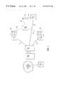
- FIG. 1is a block diagram of a mobile (cellular) telephone system, according to one embodiment of the present invention
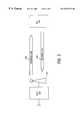
- FIG. 2is a block diagram of forward and reverse links, according to the FIG. 1 embodiment
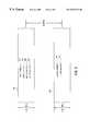
- FIG. 3illustrates the channel allocation in the links of FIG. 2, according to one embodiment of the present invention
- FIG. 4illustrates a transmit power timing diagram for the forward link of FIG. 2, according to one embodiment of the present invention
- FIG. 5illustrates the geographical hyperbolas of constant differential time of arrival, according to one embodiment of the present invention.
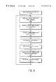
- FIG. 6illustrates a flowchart of the determination of the mobile station's geographic location, according to an embodiment of the present invention.
- FIG. 1a block diagram of a mobile (cellular) telephone system is illustrated, according to one embodiment of the present invention.
- CDMACode Division Multiple Access
- a common form of CDMA systemis one designed in accordance with Telecommunications Industry Association (TIA) specification TIA/IS-95A ( May 1995), which herein is incorporated by reference.
- TIATelecommunications Industry Association
- MSmobile switching center
- BSCbase station controller
- BTSbase transceiver stations
- MSmobile station
- the MSC 100comprises the gateway between a regional mobile telephone system and the overall public telephone network 106 .
- the E911 calls originating within the regional mobile telephone systemare routed to the public safety access point (PSAP) 108 through the public telephone network 106 by MSC 100 .
- PSAPpublic safety access point
- Associated with the MSC 100may be several databases used in controlling the mobile telephone system, such as a home location register and a visitor location register.
- the BSC 104includes a control computer for controlling the interaction of the BTSs.
- the BSC 104may control the transmit power levels in the BTSs, and may also cause the transmission of messages which will control the transmit power levels of an MS 150 .
- One of the prime functions of the BSC 104is to multiplex and de-multiplex the various control signals and voice/data channels in the mobile telephone system.
- Each BTS 110 , 120 , 130contains several transmitters and receivers, one for each frequency band.
- Each BTS 110 , 120 , 130is connected via a land-line 112 , 122 , 132 , respectively, to the BSC 104 .
- Each BTS 110 , 120 , 130is attached to an antenna 116 , 126 , 136 , respectively, via cabling.
- each BTS 110 , 120 , 130is located a very short distance away from corresponding antenna 116 , 126 , 136 .
- each transmission of the several BTSsmust be synchronized to a common time standard.
- the Global Positioning SystemGPS is used to distribute a synchronized time standard. Therefore each BTS 110 , 120 , 130 contain GPS receiver circuits sufficient to maintain a common time standard.
- An ongoing call in the CDMA mobile telephone systemincludes a wide bandwidth radio-frequency (RF) communications channel transmitted by the BTS 1 110 through antenna 116 and received by MS 1 150 , called a forward link 240 .
- the ongoing callalso includes a wide bandwidth RF communications channel transmitted by the MS 1 150 through its attached antenna (not shown) and received by BTS 1 110 , called a reverse link 280 .
- Both the forward link 240 and the reverse link 280may carry multiple calls which may be separated by a series of unique code sequences, each associated with one of the mobile stations.
- MS 1 150begins an initialization process in order to access the CDMA mobile telephone system.
- MS 1 150first determines a suitable carrier channel by scanning for the signal strength of incoming radio carrier channels. The MS 1 150 then determines the strongest radio carrier channel that contains a control channel. Once this control channel is found, MS 1 150 receives control information including, among other things, the data required for MS 1 150 to access the channel and the maximum transmit power MS 1 150 should use when initiating a call.
- BTS 1 110will transmit a control channel on forward link 140 .
- MS 1 150transmits an identifying message on reverse link 280 to identify MS 1 150 to the CDMA mobile telephone system.
- forward link 240 and reverse link 280each have 1.23 MHz bandwidth, and the center frequency of each link are separated by 45 MHz.
- the channelsare embedded within the forward link 240 and the reverse link 280 by the CDMA modulator/demodulators.
- the forward link 240uses quadrature phase shift keying (QPSK) and the reverse link 280 uses offset quadrature phase shift keying (O-QPSK). Each channel is identified by a unique code.
- pilot channels 310contain beacon, timing and phase reference, and signal strength for power control for the MS 1 150 .
- the pilot channels 310usually are the strongest RF powered signals sent from BTS 1 110 .
- the pilot channelscontain a PN code that is time shifted for identifying which BTS is transmitting.
- Sync channels 320provide MS 1 150 with time synchronization information.
- Paging channels 340are used to communicate with MS 1 150 when no call is in progress.
- the paging channels 340may contain system and access parameters necessary for the MS 1 150 to initiate calls.
- Paging channels 340may additionally contain signals indicating an incoming call is pending so that MS 1 150 may initiate the reception of an incoming call.
- Other channels 340 within forward link 240may include forward traffic channels.
- the forward traffic channelsare the primary channels used after a call is initiated to carry voice and data from BTS 1 110 to MS 1 150 .
- access channels 360carry responses generated by MS 1 150 to commands and call origination requests sent by BTS 1 110 .
- the access channels 360may additionally carry other signals generated by MS 1 150 when no reverse traffic channel is established.
- Other channels 370 within reverse link 280may include reverse traffic channels.
- the reverse traffic channelsare the primary channels used after a call is initiated to carry voice and data from MS 1 150 to BTS 1 110 .
- a special signalis used within forward link 240 for the purpose of determining the geographical location of MS 1 150 .
- This signalcalled the forward link triangulation signal (FLTS)
- FLTSforward link triangulation signal
- the FLTSmay be carried by the pilot channels 310 or it may be carried by the sync channels 320 . In other embodiments the FLTS may be carried by other circuits 340 of the forward link 240 .
- the FLTSmay be sent periodically or continuously.
- MS 1 150may receive FLTS messages from BTS 1 110 , BTS 2 120 , and BTS 3 130 .
- Each FLTS messagemay arrive at MS 1 150 at a slightly different time, depending upon the signal propagation delay occurring due to the differing signal paths 152 , 154 , 156 between MS 1 150 and antennas 116 , 126 , and 136 , respectively.
- MS 1 150may determine the time difference of arrival (TDOA) between the FLTS signals sent by BTS 1 110 , BTS 2 120 , and BTS 3 130 .
- TDOAtime difference of arrival
- TDOAtime difference between the FLTS sent by a BTS A and the FLTS sent by a BTS B
- MS 1 150may then determine TDOA ( 1 , 2 ) and TDOA ( 2 , 3 ).
- FIG. 4a transmit power timing diagram for the forward link of FIG. 2 is shown, according to one embodiment of the present invention.
- the FLTS signalsmay be transmitted in a synchronized but periodic manner.
- the average transmission power of a BTSis limited by Federal Communications Commission (FCC) rules due to concerns about health and other impacts of radiated RF energy. It is therefore not possible to maintain a high RF power transmission of CDMA forward links 240 .
- FCCFederal Communications Commission
- a CDMA mobile telephone systemconstantly adjusts the transmitted power of both the BTSs and the MSs in order to minimize the average RF power transmission within the system.
- BTS 1 110 , BTS 2 120 , and BTS 3 130may temporarily increase the baseline transmitted power X 0 dBW by an amount H dBW during the transmission time required for an FLTS.
- Hwill depend upon the transmitters within BTS 1 110 , BTS 2 120 , and BTS 3 130 , and the size of the cells within the CDMA mobile telephone system.
- the resulting increased transmitted power X 0 +H dBWincreases the likelihood that MS 1 150 will receive the FLTS signals from each one of BTS 1 110 , BTS 2 120 , and BTS 3 130 .
- the reception and subsequent determination of DTOA ( 1 , 2 ) and DTOA ( 2 , 3 )are therefore made more likely.
- the repetition period Pmay be chosen so that the time period W required to transmit a FLTS signal is small by comparison.
- the duty cycle W/Pis also small, and therefore the average transmitted power is not substantially greater than X 0 dBW. Therefore in one embodiment the ability of MS 1 150 to successfully determine the necessary DTOA values is increased without substantially increasing the average transmitted power.
- FIG. 5the geographical hyperbolas of constant differential time of arrival are illustrated, according to one embodiment of the present invention.
- FIGS. 3 and 4it was shown how the use of synchronized transmission of FLTS signals allows BS 1 150 to determine the DTOA ( 1 , 2 ) and DTOA ( 2 , 3 ). However, knowing the DTOA of several signals does not immediately give the geographic location of MS 1 150 .
- the difference between the distance from MS 1 150 to BTS 1 110 and the distance from MS 1 150 to BTS 2 120is equal to the speed of light times DTOA ( 1 , 2 ). Therefore, knowing a DTOA, the difference in distance from MS 1 150 to a pair of BTSs may be calculated.
- Point 530is located such that the distance from point 530 to antenna 126 ( 534 ) is equal to the distance from point 530 to antenna 116 ( 532 ) plus an amount equal to the speed of light times DTOA ( 1 , 2 ).
- the location of all such pointsdefines a hyperbola 510 .
- all possible points where a mobile station could potentially determine a DTOA of DTOA ( 1 , 2 )is hyperbola 510 . Notice that MS 1 150 is located upon this hyperbola 510 .
- the geographic locations of the antennas of the BTSsmay be determined in advance by surveying or by using a GPS receiver. Knowing these geographic locations and determining the DTOA times of the FLTS, the geographic location of an MS may be calculated.
- the calculation of the hyperbolas and their intersection pointmay be carried out by processors within MS 1 150 .
- MS 1 150may then transmit its geographic location to MSC 100 for forwarding to PSAP 108 when the need arises, such as when a E911 call is initiated.
- the DTOA datamay be forwarded from MS 1 150 to BSC 104 or MSC 100 .
- processors within BSC 104 or MSC 100may perform the calculation of the hyperbolas and their intersection point.
- step 610the mobile station is initialized within the CDMA mobile telephone system by receiving data from pilot channels 310 and sync channels 320 . Then in step 612 the mobile station receives the first in a series of FLTS signals from one of at least three BTSs. The mobile station notes which BTS sent the FLTS and the time of arrival, and time stamps the message. In steps 614 and 616 the mobile station similarly receives, notes the transmitting BTS and time of arrival, and timestamps the messages. Then in step 616 the mobile station determines the values of the DTOA between the three FLTS signals.
- step 620the mobile station transmits a message to the base station controller containing the DTOA information determined in step 616 .
- the base station controlleruses the DTOA information and previously stored geographic location data for the antennas of the base transceiver stations to calculate the location hyperbolas and the point where the hyperbolas intersect. This geographic location is the location of the mobile station at that point in time.
- the geographic locationis then, in step 624 , sent to temporary storage within the mobile switching center for use when required. After the current value of the geographic location of the mobile station is stored, the process repeats and, starting over at step 612 , the mobile station determines subsequent values of DTOA.
Landscapes
- Engineering & Computer Science (AREA)
- Physics & Mathematics (AREA)
- General Physics & Mathematics (AREA)
- Radar, Positioning & Navigation (AREA)
- Remote Sensing (AREA)
- Computer Networks & Wireless Communication (AREA)
- Signal Processing (AREA)
- Mobile Radio Communication Systems (AREA)
Abstract
Description
Claims (23)
Priority Applications (1)
| Application Number | Priority Date | Filing Date | Title |
|---|---|---|---|
| US09/372,153US6539229B1 (en) | 1998-08-20 | 1999-08-20 | System and method for mobile location detection in synchronous wireless systems |
Applications Claiming Priority (2)
| Application Number | Priority Date | Filing Date | Title |
|---|---|---|---|
| US9724898P | 1998-08-20 | 1998-08-20 | |
| US09/372,153US6539229B1 (en) | 1998-08-20 | 1999-08-20 | System and method for mobile location detection in synchronous wireless systems |
Publications (1)
| Publication Number | Publication Date |
|---|---|
| US6539229B1true US6539229B1 (en) | 2003-03-25 |
Family
ID=26793029
Family Applications (1)
| Application Number | Title | Priority Date | Filing Date |
|---|---|---|---|
| US09/372,153Expired - LifetimeUS6539229B1 (en) | 1998-08-20 | 1999-08-20 | System and method for mobile location detection in synchronous wireless systems |
Country Status (1)
| Country | Link |
|---|---|
| US (1) | US6539229B1 (en) |
Cited By (41)
| Publication number | Priority date | Publication date | Assignee | Title |
|---|---|---|---|---|
| US20020034384A1 (en)* | 2000-09-18 | 2002-03-21 | Mikhail Peter G. | Location sensing camera |
| US20020052208A1 (en)* | 2000-09-23 | 2002-05-02 | Koninklijke Philips Electronics N.V. | Mobile radio terminal and related method and system |
| US20020132583A1 (en)* | 2001-03-19 | 2002-09-19 | Jelinek Lenka M. | Antenna system, software and methods for locating an object |
| US20030069025A1 (en)* | 2001-10-09 | 2003-04-10 | General Electric Company | Transmitter location for ultra-wideband, transmitted-reference CDMA communication system |
| US20030088698A1 (en)* | 2001-11-06 | 2003-05-08 | Inderpreet Singh | VPN failure recovery |
| US20030114170A1 (en)* | 2001-12-14 | 2003-06-19 | Rick Roland R. | Position determination system that uses a cellular communication system |
| US20030144006A1 (en)* | 2002-01-25 | 2003-07-31 | Mikael Johansson | Methods, systems, and computer program products for determining the location of a mobile terminal based on delays in receiving data packets from transmitters having known locations |
| US20030217122A1 (en)* | 2002-03-01 | 2003-11-20 | Roese John J. | Location-based access control in a data network |
| US6658258B1 (en)* | 2000-09-29 | 2003-12-02 | Lucent Technologies Inc. | Method and apparatus for estimating the location of a mobile terminal |
| US20040106413A1 (en)* | 2001-03-30 | 2004-06-03 | Marco Sambin | Transmission method for cellular telephony mobile equipment's location data |
| US20050057395A1 (en)* | 2001-08-03 | 2005-03-17 | Atkinson Simon John | Method of determining the position of a target using transmitters of opportunity |
| US20050162314A1 (en)* | 2001-07-18 | 2005-07-28 | Bromley Patrick G. | Method and system for processing positioning signals based on predetermined message data segment |
| US20050195756A1 (en)* | 2004-02-26 | 2005-09-08 | Frattura David E. | Status announcement system and method |
| US20050195949A1 (en)* | 2004-02-26 | 2005-09-08 | Frattura David E. | Status transmission system and method |
| US20050215269A1 (en)* | 2004-02-17 | 2005-09-29 | Jadi Inc. | Navigation system |
| US20050282558A1 (en)* | 2004-06-21 | 2005-12-22 | Korea Electrotechnology Research Institute | System and method for asynchronous wireless positioning by ordered transmission |
| US20060030333A1 (en)* | 1999-01-08 | 2006-02-09 | Ward Matthew L | Geo-fencing in a wireless location system |
| US20060036730A1 (en)* | 2004-08-06 | 2006-02-16 | Richard Graham | System and method for address block enhanced dynamic network policy management |
| US20060037075A1 (en)* | 2004-03-10 | 2006-02-16 | Frattura David E | Dynamic network detection system and method |
| US20060080004A1 (en)* | 2004-04-29 | 2006-04-13 | Jadi Inc. | Self-leveling laser horizon for navigation guidance |
| US20060229088A1 (en)* | 2005-04-12 | 2006-10-12 | Sbc Knowledge Ventures L.P. | Voice broadcast location system |
| US20070053340A1 (en)* | 2005-08-09 | 2007-03-08 | Guilford John H | Time synchronization system and method for synchronizing locating units within a communication system using a known external signal |
| US20070078974A1 (en)* | 2005-06-28 | 2007-04-05 | Krishnan Venkatraman G | Time synchronized wireless method and operations |
| US20080214205A1 (en)* | 2007-02-05 | 2008-09-04 | Commscope, Inc. Of North Carolina | System and method for generating a location estimate using a method of intersections |
| US20080234930A1 (en)* | 2007-03-21 | 2008-09-25 | Jadi Inc. | Navigation unit and base station |
| US20090268665A1 (en)* | 2008-04-28 | 2009-10-29 | Newport Media, Inc. | Method and Apparatus for Locating MediaFLO Capable Wireless Devices |
| US7611292B2 (en) | 2004-11-08 | 2009-11-03 | Enterasys Networks, Inc. | Optical interface identification system |
| US20100125622A1 (en)* | 2008-11-20 | 2010-05-20 | Sony Computer Entertainment Inc. | Modifying virtual item states in conjunction with digital broadcast |
| US20100153465A1 (en)* | 2008-12-17 | 2010-06-17 | Verizon Data Services Llc | System and method for providing image geo-metadata mapping |
| EP1582850A3 (en)* | 2004-03-30 | 2010-12-22 | Tamtron Oy | Method and apparatus for improving accurary of weighing measurements |
| US20110009129A1 (en)* | 2009-07-13 | 2011-01-13 | Jong Bu Lim | Device and method of estimating location of terminal using sequences transmitted from base stations |
| GB2484916A (en)* | 2010-10-25 | 2012-05-02 | Percello Ltd | Locating a 3G mobile handset within a cellular network |
| US8213957B2 (en) | 2009-04-22 | 2012-07-03 | Trueposition, Inc. | Network autonomous wireless location system |
| US9052374B2 (en) | 2001-07-18 | 2015-06-09 | Fast Location.Net, Llc | Method and system for processing positioning signals based on predetermined message data segment |
| US20150160329A1 (en)* | 2012-05-30 | 2015-06-11 | Nokia Corporation | Determining location and orientation of directional tranceivers |
| US9641693B2 (en)* | 1999-03-26 | 2017-05-02 | Swisscom Ag | Chip card with integrated time-determining system |
| US9736809B2 (en)* | 2014-02-05 | 2017-08-15 | Sony Corporation | Method for improved indoor positioning and crowd sourcing using PDR |
| US9888353B2 (en) | 2001-10-04 | 2018-02-06 | Traxcell Technologies Llc | Mobile wireless communications system and method with hierarchical location determination |
| US9940827B2 (en) | 2013-04-30 | 2018-04-10 | Provenance Asset Group Llc | Controlling operation of a device |
| US9955309B2 (en) | 2012-01-23 | 2018-04-24 | Provenance Asset Group Llc | Collecting positioning reference data |
| JP2022518691A (en)* | 2019-01-18 | 2022-03-16 | エキサロクス オイ | Positioning based on signal propagation time difference |
Citations (7)
| Publication number | Priority date | Publication date | Assignee | Title |
|---|---|---|---|---|
| US4494119A (en)* | 1983-08-04 | 1985-01-15 | 122923 Canada Limited | Distress radiolocation method and system |
| EP0767594A2 (en)* | 1995-10-03 | 1997-04-09 | Nokia Mobile Phones Ltd. | Mobile station positioning system |
| US5815538A (en)* | 1993-06-25 | 1998-09-29 | Omniplex, Inc. | Method and apparatus for determining location of a subscriber device in a wireless cellular communications system |
| US5903844A (en)* | 1997-02-04 | 1999-05-11 | Motorola, Inc. | Method and apparatus for determining remote unit location in a communication system |
| US5943014A (en)* | 1996-06-06 | 1999-08-24 | Qualcom Incorporated | Using a signal with increased power for determining the position of a mobile subscriber in a CDMA cellular telephone system |
| US6212391B1 (en)* | 1997-12-01 | 2001-04-03 | Motorola, Inc. | Method for positioning gsm mobile station |
| US6230018B1 (en)* | 1998-05-14 | 2001-05-08 | Nortel Networks Limited | Devices and processing in a mobile radio communication network having calibration terminals |
- 1999
- 1999-08-20USUS09/372,153patent/US6539229B1/ennot_activeExpired - Lifetime
Patent Citations (7)
| Publication number | Priority date | Publication date | Assignee | Title |
|---|---|---|---|---|
| US4494119A (en)* | 1983-08-04 | 1985-01-15 | 122923 Canada Limited | Distress radiolocation method and system |
| US5815538A (en)* | 1993-06-25 | 1998-09-29 | Omniplex, Inc. | Method and apparatus for determining location of a subscriber device in a wireless cellular communications system |
| EP0767594A2 (en)* | 1995-10-03 | 1997-04-09 | Nokia Mobile Phones Ltd. | Mobile station positioning system |
| US5943014A (en)* | 1996-06-06 | 1999-08-24 | Qualcom Incorporated | Using a signal with increased power for determining the position of a mobile subscriber in a CDMA cellular telephone system |
| US5903844A (en)* | 1997-02-04 | 1999-05-11 | Motorola, Inc. | Method and apparatus for determining remote unit location in a communication system |
| US6212391B1 (en)* | 1997-12-01 | 2001-04-03 | Motorola, Inc. | Method for positioning gsm mobile station |
| US6230018B1 (en)* | 1998-05-14 | 2001-05-08 | Nortel Networks Limited | Devices and processing in a mobile radio communication network having calibration terminals |
Cited By (92)
| Publication number | Priority date | Publication date | Assignee | Title |
|---|---|---|---|---|
| US8838139B2 (en) | 1999-01-08 | 2014-09-16 | Trueposition, Inc. | Advanced triggers for location-based service applications in a wireless location system |
| US7783299B2 (en) | 1999-01-08 | 2010-08-24 | Trueposition, Inc. | Advanced triggers for location-based service applications in a wireless location system |
| US20100227628A1 (en)* | 1999-01-08 | 2010-09-09 | Trueposition, Inc. | Advanced Triggers for Location-Based Service Applications in a Wireless Location System |
| US8320931B2 (en) | 1999-01-08 | 2012-11-27 | Trueposition, Inc. | Geo-fencing in a wireless location system |
| US8509805B2 (en) | 1999-01-08 | 2013-08-13 | Trueposition, Inc. | Advanced triggers for location-based service applications in a wireless location system |
| US20060030333A1 (en)* | 1999-01-08 | 2006-02-09 | Ward Matthew L | Geo-fencing in a wireless location system |
| US9288628B2 (en) | 1999-01-08 | 2016-03-15 | Trueposition, Inc. | Advanced triggers for location-based service applications in a wireless location system |
| US9641693B2 (en)* | 1999-03-26 | 2017-05-02 | Swisscom Ag | Chip card with integrated time-determining system |
| US20020034384A1 (en)* | 2000-09-18 | 2002-03-21 | Mikhail Peter G. | Location sensing camera |
| US20020052208A1 (en)* | 2000-09-23 | 2002-05-02 | Koninklijke Philips Electronics N.V. | Mobile radio terminal and related method and system |
| US7155237B2 (en)* | 2000-09-23 | 2006-12-26 | Koninklijke Philips Electronics N.V. | Method and system for determining position of a mobile terminal utilizing time of arrival calculation in combination with a time difference of arrival calculation |
| US6658258B1 (en)* | 2000-09-29 | 2003-12-02 | Lucent Technologies Inc. | Method and apparatus for estimating the location of a mobile terminal |
| US20020132583A1 (en)* | 2001-03-19 | 2002-09-19 | Jelinek Lenka M. | Antenna system, software and methods for locating an object |
| US7110776B2 (en)* | 2001-03-30 | 2006-09-19 | Telecom Italia S.P.A. | Transmission method for cellular telephony mobile equipment's location data |
| US7751831B2 (en)* | 2001-03-30 | 2010-07-06 | Telecom Italia S.P.A. | Method of transmitting cellular telephone location data |
| US20040106413A1 (en)* | 2001-03-30 | 2004-06-03 | Marco Sambin | Transmission method for cellular telephony mobile equipment's location data |
| US20060276203A1 (en)* | 2001-03-30 | 2006-12-07 | Telecom Italia S.P.A. | Method of transmitting cellular telephone location data |
| US20100090894A1 (en)* | 2001-07-18 | 2010-04-15 | Fast Location Net, Llc | Method and System for Processing Positioning Signals Based on Predetermined Message Data Segment |
| US8102312B2 (en) | 2001-07-18 | 2012-01-24 | Fast Location.Net, Llc | Method and system for processing positioning signals based on predetermined message data segment |
| US20070120735A1 (en)* | 2001-07-18 | 2007-05-31 | Fast Location.Net, Llc | Method and System for Processing Positioning Signals Based on Predetermined Message Data Segment |
| US7633439B2 (en)* | 2001-07-18 | 2009-12-15 | Fast Location.Net, Llc | Method and system for processing positioning signals based on predetermined message data segment |
| US9052374B2 (en) | 2001-07-18 | 2015-06-09 | Fast Location.Net, Llc | Method and system for processing positioning signals based on predetermined message data segment |
| US20050162314A1 (en)* | 2001-07-18 | 2005-07-28 | Bromley Patrick G. | Method and system for processing positioning signals based on predetermined message data segment |
| US7154437B2 (en)* | 2001-07-18 | 2006-12-26 | Fast Location.Net, Llc | Method and system for processing positioning signals based on predetermined message data segment |
| US20050057395A1 (en)* | 2001-08-03 | 2005-03-17 | Atkinson Simon John | Method of determining the position of a target using transmitters of opportunity |
| US7155240B2 (en)* | 2001-08-03 | 2006-12-26 | Roke Manor Research Limited | Method of determining the position of a target using transmitters of opportunity |
| US10820147B2 (en) | 2001-10-04 | 2020-10-27 | Traxcell Technologies, LLC | Mobile wireless device providing off-line and on-line geographic navigation information |
| US10390175B2 (en) | 2001-10-04 | 2019-08-20 | Traxcell Technologies Llc | Mobile wireless device tracking and notification system |
| US9888353B2 (en) | 2001-10-04 | 2018-02-06 | Traxcell Technologies Llc | Mobile wireless communications system and method with hierarchical location determination |
| US10448209B2 (en) | 2001-10-04 | 2019-10-15 | Traxcell Technologies Llc | Wireless network and method with communications error trend analysis |
| US9918196B2 (en) | 2001-10-04 | 2018-03-13 | Traxcell Technologies Llc | Internet queried directional navigation system with mobile and fixed originating location determination |
| US11445328B2 (en) | 2001-10-04 | 2022-09-13 | Traxcell Technologies, LLC | Wireless network and method for suggesting corrective action and restricting communications in response to detecting communications errors |
| US10743135B2 (en) | 2001-10-04 | 2020-08-11 | Traxcell Technologies, LLC | Wireless network and method for suggesting corrective action in response to detecting communications errors |
| US10701517B1 (en) | 2001-10-04 | 2020-06-30 | Traxcell Technologies Llc | Wireless network and method for suggesting corrective action based on performance and controlling access to location information |
| US20030069025A1 (en)* | 2001-10-09 | 2003-04-10 | General Electric Company | Transmitter location for ultra-wideband, transmitted-reference CDMA communication system |
| US7269427B2 (en)* | 2001-10-09 | 2007-09-11 | General Electric Company | Transmitter location for ultra-wideband, transmitted-reference CDMA communication system |
| US20030088698A1 (en)* | 2001-11-06 | 2003-05-08 | Inderpreet Singh | VPN failure recovery |
| US7647422B2 (en) | 2001-11-06 | 2010-01-12 | Enterasys Networks, Inc. | VPN failure recovery |
| US7877100B2 (en) | 2001-12-14 | 2011-01-25 | Qualcomm Incorporated | Position determination system that uses A cellular communication system |
| US20030114170A1 (en)* | 2001-12-14 | 2003-06-19 | Rick Roland R. | Position determination system that uses a cellular communication system |
| US20090305726A1 (en)* | 2001-12-14 | 2009-12-10 | Qualcomm Incorporated | Position Determination System That Uses A Cellular Communication System |
| US20030144006A1 (en)* | 2002-01-25 | 2003-07-31 | Mikael Johansson | Methods, systems, and computer program products for determining the location of a mobile terminal based on delays in receiving data packets from transmitters having known locations |
| US7739402B2 (en) | 2002-03-01 | 2010-06-15 | Enterasys Networks, Inc. | Locating devices in a data network |
| US20030217122A1 (en)* | 2002-03-01 | 2003-11-20 | Roese John J. | Location-based access control in a data network |
| US7706369B2 (en) | 2002-03-01 | 2010-04-27 | Enterasys Networks, Inc. | Location discovery in a data network |
| US8972589B2 (en)* | 2002-03-01 | 2015-03-03 | Enterasys Networks, Inc. | Location-based access control in a data network |
| US7606938B2 (en) | 2002-03-01 | 2009-10-20 | Enterasys Networks, Inc. | Verified device locations in a data network |
| US8010133B2 (en) | 2004-02-17 | 2011-08-30 | Nav-Track, Inc. | Navigation system |
| US20080103696A1 (en)* | 2004-02-17 | 2008-05-01 | Jadi Inc. | Navigation system |
| US7983694B2 (en) | 2004-02-17 | 2011-07-19 | Nav-Track, Inc. | Target and base station for a navigation system |
| US20050215269A1 (en)* | 2004-02-17 | 2005-09-29 | Jadi Inc. | Navigation system |
| US20080167051A1 (en)* | 2004-02-17 | 2008-07-10 | Jadi Inc. | Navigation system |
| US7403783B2 (en) | 2004-02-17 | 2008-07-22 | Jadi, Inc. | Navigation system |
| US7580403B2 (en) | 2004-02-26 | 2009-08-25 | Enterasys Networks, Inc. | Status transmission system and method |
| US20050195949A1 (en)* | 2004-02-26 | 2005-09-08 | Frattura David E. | Status transmission system and method |
| US20050195756A1 (en)* | 2004-02-26 | 2005-09-08 | Frattura David E. | Status announcement system and method |
| US20060037075A1 (en)* | 2004-03-10 | 2006-02-16 | Frattura David E | Dynamic network detection system and method |
| EP1582850A3 (en)* | 2004-03-30 | 2010-12-22 | Tamtron Oy | Method and apparatus for improving accurary of weighing measurements |
| US20060080004A1 (en)* | 2004-04-29 | 2006-04-13 | Jadi Inc. | Self-leveling laser horizon for navigation guidance |
| US7908041B2 (en) | 2004-04-29 | 2011-03-15 | Munro & Associates, Inc. | Self-leveling laser horizon for navigation guidance |
| US7411551B2 (en)* | 2004-06-21 | 2008-08-12 | Korea Electrotechnology Research Institute | System and method for asynchronous wireless positioning by ordered transmission |
| US20050282558A1 (en)* | 2004-06-21 | 2005-12-22 | Korea Electrotechnology Research Institute | System and method for asynchronous wireless positioning by ordered transmission |
| US20060036730A1 (en)* | 2004-08-06 | 2006-02-16 | Richard Graham | System and method for address block enhanced dynamic network policy management |
| US7945945B2 (en) | 2004-08-06 | 2011-05-17 | Enterasys Networks, Inc. | System and method for address block enhanced dynamic network policy management |
| US7611292B2 (en) | 2004-11-08 | 2009-11-03 | Enterasys Networks, Inc. | Optical interface identification system |
| US20060229088A1 (en)* | 2005-04-12 | 2006-10-12 | Sbc Knowledge Ventures L.P. | Voice broadcast location system |
| US8086232B2 (en) | 2005-06-28 | 2011-12-27 | Enterasys Networks, Inc. | Time synchronized wireless method and operations |
| US20070078974A1 (en)* | 2005-06-28 | 2007-04-05 | Krishnan Venkatraman G | Time synchronized wireless method and operations |
| US20070053340A1 (en)* | 2005-08-09 | 2007-03-08 | Guilford John H | Time synchronization system and method for synchronizing locating units within a communication system using a known external signal |
| US7411937B2 (en)* | 2005-08-09 | 2008-08-12 | Agilent Technologies, Inc. | Time synchronization system and method for synchronizing locating units within a communication system using a known external signal |
| US20080214205A1 (en)* | 2007-02-05 | 2008-09-04 | Commscope, Inc. Of North Carolina | System and method for generating a location estimate using a method of intersections |
| US8090384B2 (en)* | 2007-02-05 | 2012-01-03 | Andrew, Llc | System and method for generating a location estimate using a method of intersections |
| US20080234930A1 (en)* | 2007-03-21 | 2008-09-25 | Jadi Inc. | Navigation unit and base station |
| US8214147B2 (en) | 2007-03-21 | 2012-07-03 | Nav-Track, Inc. | Navigation unit and base station |
| US8077659B2 (en)* | 2008-04-28 | 2011-12-13 | Newport Media, Inc. | Method and apparatus for locating mobile multimedia multicast system capable wireless devices |
| US20090268665A1 (en)* | 2008-04-28 | 2009-10-29 | Newport Media, Inc. | Method and Apparatus for Locating MediaFLO Capable Wireless Devices |
| US20100125622A1 (en)* | 2008-11-20 | 2010-05-20 | Sony Computer Entertainment Inc. | Modifying virtual item states in conjunction with digital broadcast |
| US9646008B2 (en)* | 2008-11-20 | 2017-05-09 | Sony Interactive Entertainment Inc. | Modifying virtual item states in conjunction with digital broadcast |
| US20100153465A1 (en)* | 2008-12-17 | 2010-06-17 | Verizon Data Services Llc | System and method for providing image geo-metadata mapping |
| US8213957B2 (en) | 2009-04-22 | 2012-07-03 | Trueposition, Inc. | Network autonomous wireless location system |
| EP2454916A4 (en)* | 2009-07-13 | 2013-01-09 | Samsung Electronics Co Ltd | DEVICE AND METHOD FOR ESTIMATING THE POSITION OF A TERMINAL USING SEQUENCES EMITTED BY BASE STATIONS |
| US8543136B2 (en) | 2009-07-13 | 2013-09-24 | Samsung Electronics Co., Ltd. | Device and method of estimating location of terminal using sequences transmitted from base stations |
| US20110009129A1 (en)* | 2009-07-13 | 2011-01-13 | Jong Bu Lim | Device and method of estimating location of terminal using sequences transmitted from base stations |
| US8781497B2 (en) | 2010-10-25 | 2014-07-15 | Broadcom Corporation | Passive locating of UMTS handsets |
| GB2484916B (en)* | 2010-10-25 | 2013-02-27 | Percello Ltd | Passive locating of umts handsets |
| GB2484916A (en)* | 2010-10-25 | 2012-05-02 | Percello Ltd | Locating a 3G mobile handset within a cellular network |
| US9955309B2 (en) | 2012-01-23 | 2018-04-24 | Provenance Asset Group Llc | Collecting positioning reference data |
| US9939516B2 (en)* | 2012-05-30 | 2018-04-10 | Provenance Asset Group Llc | Determining location and orientation of directional transceivers |
| US20150160329A1 (en)* | 2012-05-30 | 2015-06-11 | Nokia Corporation | Determining location and orientation of directional tranceivers |
| US9940827B2 (en) | 2013-04-30 | 2018-04-10 | Provenance Asset Group Llc | Controlling operation of a device |
| US9736809B2 (en)* | 2014-02-05 | 2017-08-15 | Sony Corporation | Method for improved indoor positioning and crowd sourcing using PDR |
| JP2022518691A (en)* | 2019-01-18 | 2022-03-16 | エキサロクス オイ | Positioning based on signal propagation time difference |
Similar Documents
| Publication | Publication Date | Title |
|---|---|---|
| US6539229B1 (en) | System and method for mobile location detection in synchronous wireless systems | |
| US6999778B2 (en) | Multipath assistance for pilot phase measurement processes | |
| US5600706A (en) | Method and system for determining the position of a mobile receiver | |
| EP2167987B1 (en) | Facilitating mobile station location using a ground-based cellular network | |
| US5404376A (en) | Navigation assistance for call handling in mobile telephone systems | |
| CA2303264C (en) | Method and system for determining position of a cellular mobile terminal | |
| US8326324B2 (en) | Systems and methods for location positioning within radio access systems | |
| CA2489816C (en) | Method and system for locating a mobile subscriber in a cdma communication system | |
| MXPA02001057A (en) | Method and apparatus for paging a user terminal within the satellite higher gain spotbeam. | |
| JP2000092564A (en) | Expanded range concentric cell base station | |
| KR20000017641A (en) | Extended range concentric cell base station | |
| EP1034678B1 (en) | Method and system for determining position of mobile radio terminals | |
| EP1329125B1 (en) | Mobile station and method of locating the mobile station | |
| US7616957B2 (en) | Systems and methods for wireless location based services | |
| AU2002302027B2 (en) | Method and system for locating a mobile subscriber in a cdma communication system | |
| HK1076343B (en) | Method and system for locating a mobile subscriber in a cdma communication system |
Legal Events
| Date | Code | Title | Description |
|---|---|---|---|
| AS | Assignment | Owner name:SONY ELECTRONICS, INC., NEW JERSEY Free format text:ASSIGNMENT OF ASSIGNORS INTEREST;ASSIGNOR:ALI, FARHAN;REEL/FRAME:010194/0886 Effective date:19990818 Owner name:SONY CORPORATION, JAPAN Free format text:ASSIGNMENT OF ASSIGNORS INTEREST;ASSIGNOR:ALI, FARHAN;REEL/FRAME:010194/0886 Effective date:19990818 | |
| STCF | Information on status: patent grant | Free format text:PATENTED CASE | |
| FPAY | Fee payment | Year of fee payment:4 | |
| AS | Assignment | Owner name:SONY CORPORATION, JAPAN Free format text:ASSIGNMENT OF ASSIGNORS INTEREST;ASSIGNOR:SONY ELECTRONICS INC.;REEL/FRAME:023814/0736 Effective date:20100111 | |
| AS | Assignment | Owner name:SCA IPLA HOLDINGS INC.,NEW YORK Free format text:ASSIGNMENT OF ASSIGNORS INTEREST;ASSIGNOR:SONY CORPORATION;REEL/FRAME:023828/0473 Effective date:20100108 Owner name:MOBILEMEDIA IDEAS LLC,MARYLAND Free format text:ASSIGNMENT OF ASSIGNORS INTEREST;ASSIGNOR:SCA IPLA HOLDINGS INC;REEL/FRAME:023828/0504 Effective date:20100111 Owner name:SCA IPLA HOLDINGS INC., NEW YORK Free format text:ASSIGNMENT OF ASSIGNORS INTEREST;ASSIGNOR:SONY CORPORATION;REEL/FRAME:023828/0473 Effective date:20100108 Owner name:MOBILEMEDIA IDEAS LLC, MARYLAND Free format text:ASSIGNMENT OF ASSIGNORS INTEREST;ASSIGNOR:SCA IPLA HOLDINGS INC;REEL/FRAME:023828/0504 Effective date:20100111 | |
| FPAY | Fee payment | Year of fee payment:8 | |
| FPAY | Fee payment | Year of fee payment:12 | |
| AS | Assignment | Owner name:IRONWORKS PATENTS LLC, ILLINOIS Free format text:ASSIGNMENT OF ASSIGNORS INTEREST;ASSIGNOR:MOBILEMEDIA IDEAS LLC;REEL/FRAME:042107/0440 Effective date:20170327 |