US6537288B2 - Implantable medical device such as an anastomosis device - Google Patents
Implantable medical device such as an anastomosis deviceDownload PDFInfo
- Publication number
- US6537288B2 US6537288B2US10/003,406US340601AUS6537288B2US 6537288 B2US6537288 B2US 6537288B2US 340601 AUS340601 AUS 340601AUS 6537288 B2US6537288 B2US 6537288B2
- Authority
- US
- United States
- Prior art keywords
- linkage
- members
- anastomosis device
- flange
- vessel
- Prior art date
- Legal status (The legal status is an assumption and is not a legal conclusion. Google has not performed a legal analysis and makes no representation as to the accuracy of the status listed.)
- Expired - Lifetime, expires
Links
- 230000003872anastomosisEffects0.000titleclaimsabstractdescription135
- 230000015572biosynthetic processEffects0.000claimsabstractdescription17
- 239000007943implantSubstances0.000abstractdescription36
- 238000000034methodMethods0.000abstractdescription18
- 230000006835compressionEffects0.000abstractdescription8
- 238000007906compressionMethods0.000abstractdescription8
- 238000000926separation methodMethods0.000abstract1
- 229910003460diamondInorganic materials0.000description18
- 239000010432diamondSubstances0.000description18
- 210000000709aortaAnatomy0.000description17
- 238000005452bendingMethods0.000description16
- 239000000463materialSubstances0.000description12
- 210000004351coronary vesselAnatomy0.000description11
- 210000001519tissueAnatomy0.000description10
- 238000004873anchoringMethods0.000description7
- 210000001367arteryAnatomy0.000description6
- 230000017531blood circulationEffects0.000description6
- 238000003780insertionMethods0.000description5
- 230000037431insertionEffects0.000description5
- 230000007246mechanismEffects0.000description5
- 239000008280bloodSubstances0.000description4
- 210000004369bloodAnatomy0.000description4
- 208000029078coronary artery diseaseDiseases0.000description4
- 238000013461designMethods0.000description4
- 210000002216heartAnatomy0.000description4
- 230000007480spreadingEffects0.000description4
- 238000003892spreadingMethods0.000description4
- 210000003462veinAnatomy0.000description4
- 238000003466weldingMethods0.000description4
- 230000002612cardiopulmonary effectEffects0.000description3
- 208000014674injuryDiseases0.000description3
- 230000003902lesionEffects0.000description3
- 230000033001locomotionEffects0.000description3
- 238000000465mouldingMethods0.000description3
- 210000003739neckAnatomy0.000description3
- 230000008569processEffects0.000description3
- 238000001356surgical procedureMethods0.000description3
- 230000008733traumaEffects0.000description3
- 230000002792vascularEffects0.000description3
- 208000031481Pathologic ConstrictionDiseases0.000description2
- 230000003143atherosclerotic effectEffects0.000description2
- 210000004204blood vesselAnatomy0.000description2
- 210000000038chestAnatomy0.000description2
- 229910052751metalInorganic materials0.000description2
- 239000002184metalSubstances0.000description2
- 210000004165myocardiumAnatomy0.000description2
- 229910001000nickel titaniumInorganic materials0.000description2
- 210000000056organAnatomy0.000description2
- 230000000149penetrating effectEffects0.000description2
- 239000010935stainless steelSubstances0.000description2
- 229910001220stainless steelInorganic materials0.000description2
- 230000036262stenosisEffects0.000description2
- 208000037804stenosisDiseases0.000description2
- 230000007704transitionEffects0.000description2
- 206010022680Intestinal ischaemiaDiseases0.000description1
- 208000012902Nervous system diseaseDiseases0.000description1
- 208000001647Renal InsufficiencyDiseases0.000description1
- 208000006011StrokeDiseases0.000description1
- 208000007536ThrombosisDiseases0.000description1
- 206010052664Vascular shuntDiseases0.000description1
- HZEWFHLRYVTOIW-UHFFFAOYSA-N[Ti].[Ni]Chemical compound[Ti].[Ni]HZEWFHLRYVTOIW-UHFFFAOYSA-N0.000description1
- 230000004913activationEffects0.000description1
- 238000004026adhesive bondingMethods0.000description1
- 229910045601alloyInorganic materials0.000description1
- 239000000956alloySubstances0.000description1
- 210000002376aorta thoracicAnatomy0.000description1
- 238000013459approachMethods0.000description1
- 238000010009beatingMethods0.000description1
- 210000000013bile ductAnatomy0.000description1
- 238000001574biopsyMethods0.000description1
- 230000036772blood pressureEffects0.000description1
- 230000002308calcificationEffects0.000description1
- 238000006243chemical reactionMethods0.000description1
- 239000012141concentrateSubstances0.000description1
- 230000006378damageEffects0.000description1
- 201000010099diseaseDiseases0.000description1
- 208000037265diseases, disorders, signs and symptomsDiseases0.000description1
- 238000006073displacement reactionMethods0.000description1
- 230000000694effectsEffects0.000description1
- 239000012530fluidSubstances0.000description1
- 239000012634fragmentSubstances0.000description1
- 208000028867ischemiaDiseases0.000description1
- 201000006370kidney failureDiseases0.000description1
- 238000003698laser cuttingMethods0.000description1
- 210000004072lungAnatomy0.000description1
- 210000001349mammary arteryAnatomy0.000description1
- 238000002324minimally invasive surgeryMethods0.000description1
- 238000012978minimally invasive surgical procedureMethods0.000description1
- 238000012986modificationMethods0.000description1
- 230000004048modificationEffects0.000description1
- 230000004768organ dysfunctionEffects0.000description1
- 230000002093peripheral effectEffects0.000description1
- 238000004080punchingMethods0.000description1
- 208000037803restenosisDiseases0.000description1
- 210000003752saphenous veinAnatomy0.000description1
- 210000001562sternumAnatomy0.000description1
- 238000002054transplantationMethods0.000description1
- 238000011144upstream manufacturingMethods0.000description1
Images


Classifications
- A—HUMAN NECESSITIES
- A61—MEDICAL OR VETERINARY SCIENCE; HYGIENE
- A61B—DIAGNOSIS; SURGERY; IDENTIFICATION
- A61B17/00—Surgical instruments, devices or methods
- A61B17/32—Surgical cutting instruments
- A61B17/3205—Excision instruments
- A61B17/32053—Punch like cutting instruments, e.g. using a cylindrical or oval knife
- A—HUMAN NECESSITIES
- A61—MEDICAL OR VETERINARY SCIENCE; HYGIENE
- A61B—DIAGNOSIS; SURGERY; IDENTIFICATION
- A61B17/00—Surgical instruments, devices or methods
- A61B17/11—Surgical instruments, devices or methods for performing anastomosis; Buttons for anastomosis
- A—HUMAN NECESSITIES
- A61—MEDICAL OR VETERINARY SCIENCE; HYGIENE
- A61F—FILTERS IMPLANTABLE INTO BLOOD VESSELS; PROSTHESES; DEVICES PROVIDING PATENCY TO, OR PREVENTING COLLAPSING OF, TUBULAR STRUCTURES OF THE BODY, e.g. STENTS; ORTHOPAEDIC, NURSING OR CONTRACEPTIVE DEVICES; FOMENTATION; TREATMENT OR PROTECTION OF EYES OR EARS; BANDAGES, DRESSINGS OR ABSORBENT PADS; FIRST-AID KITS
- A61F2/00—Filters implantable into blood vessels; Prostheses, i.e. artificial substitutes or replacements for parts of the body; Appliances for connecting them with the body; Devices providing patency to, or preventing collapsing of, tubular structures of the body, e.g. stents
- A61F2/02—Prostheses implantable into the body
- A61F2/04—Hollow or tubular parts of organs, e.g. bladders, tracheae, bronchi or bile ducts
- A61F2/06—Blood vessels
- A61F2/064—Blood vessels with special features to facilitate anastomotic coupling
- A—HUMAN NECESSITIES
- A61—MEDICAL OR VETERINARY SCIENCE; HYGIENE
- A61B—DIAGNOSIS; SURGERY; IDENTIFICATION
- A61B17/00—Surgical instruments, devices or methods
- A61B17/064—Surgical staples, i.e. penetrating the tissue
- A—HUMAN NECESSITIES
- A61—MEDICAL OR VETERINARY SCIENCE; HYGIENE
- A61B—DIAGNOSIS; SURGERY; IDENTIFICATION
- A61B17/00—Surgical instruments, devices or methods
- A61B17/064—Surgical staples, i.e. penetrating the tissue
- A61B17/0644—Surgical staples, i.e. penetrating the tissue penetrating the tissue, deformable to closed position
- A—HUMAN NECESSITIES
- A61—MEDICAL OR VETERINARY SCIENCE; HYGIENE
- A61B—DIAGNOSIS; SURGERY; IDENTIFICATION
- A61B17/00—Surgical instruments, devices or methods
- A61B17/11—Surgical instruments, devices or methods for performing anastomosis; Buttons for anastomosis
- A61B17/115—Staplers for performing anastomosis, e.g. in a single operation
- A—HUMAN NECESSITIES
- A61—MEDICAL OR VETERINARY SCIENCE; HYGIENE
- A61B—DIAGNOSIS; SURGERY; IDENTIFICATION
- A61B17/00—Surgical instruments, devices or methods
- A61B17/34—Trocars; Puncturing needles
- A61B17/3415—Trocars; Puncturing needles for introducing tubes or catheters, e.g. gastrostomy tubes, drain catheters
- A—HUMAN NECESSITIES
- A61—MEDICAL OR VETERINARY SCIENCE; HYGIENE
- A61B—DIAGNOSIS; SURGERY; IDENTIFICATION
- A61B17/00—Surgical instruments, devices or methods
- A61B17/34—Trocars; Puncturing needles
- A61B17/3417—Details of tips or shafts, e.g. grooves, expandable, bendable; Multiple coaxial sliding cannulas, e.g. for dilating
- A61B17/3421—Cannulas
- A61B17/3439—Cannulas with means for changing the inner diameter of the cannula, e.g. expandable
- A—HUMAN NECESSITIES
- A61—MEDICAL OR VETERINARY SCIENCE; HYGIENE
- A61B—DIAGNOSIS; SURGERY; IDENTIFICATION
- A61B17/00—Surgical instruments, devices or methods
- A61B17/34—Trocars; Puncturing needles
- A61B17/3468—Trocars; Puncturing needles for implanting or removing devices, e.g. prostheses, implants, seeds, wires
- A—HUMAN NECESSITIES
- A61—MEDICAL OR VETERINARY SCIENCE; HYGIENE
- A61B—DIAGNOSIS; SURGERY; IDENTIFICATION
- A61B17/00—Surgical instruments, devices or methods
- A61B17/00234—Surgical instruments, devices or methods for minimally invasive surgery
- A61B2017/00238—Type of minimally invasive operation
- A61B2017/00243—Type of minimally invasive operation cardiac
- A61B2017/00247—Making holes in the wall of the heart, e.g. laser Myocardial revascularization
- A—HUMAN NECESSITIES
- A61—MEDICAL OR VETERINARY SCIENCE; HYGIENE
- A61B—DIAGNOSIS; SURGERY; IDENTIFICATION
- A61B17/00—Surgical instruments, devices or methods
- A61B17/064—Surgical staples, i.e. penetrating the tissue
- A61B2017/0641—Surgical staples, i.e. penetrating the tissue having at least three legs as part of one single body
- A—HUMAN NECESSITIES
- A61—MEDICAL OR VETERINARY SCIENCE; HYGIENE
- A61B—DIAGNOSIS; SURGERY; IDENTIFICATION
- A61B17/00—Surgical instruments, devices or methods
- A61B17/11—Surgical instruments, devices or methods for performing anastomosis; Buttons for anastomosis
- A61B2017/1107—Surgical instruments, devices or methods for performing anastomosis; Buttons for anastomosis for blood vessels
- A—HUMAN NECESSITIES
- A61—MEDICAL OR VETERINARY SCIENCE; HYGIENE
- A61B—DIAGNOSIS; SURGERY; IDENTIFICATION
- A61B17/00—Surgical instruments, devices or methods
- A61B17/11—Surgical instruments, devices or methods for performing anastomosis; Buttons for anastomosis
- A61B2017/1135—End-to-side connections, e.g. T- or Y-connections
- A—HUMAN NECESSITIES
- A61—MEDICAL OR VETERINARY SCIENCE; HYGIENE
- A61B—DIAGNOSIS; SURGERY; IDENTIFICATION
- A61B17/00—Surgical instruments, devices or methods
- A61B17/28—Surgical forceps
- A61B17/29—Forceps for use in minimally invasive surgery
- A61B17/2909—Handles
- A61B2017/2912—Handles transmission of forces to actuating rod or piston
- A61B2017/2913—Handles transmission of forces to actuating rod or piston cams or guiding means
- A61B2017/2915—Handles transmission of forces to actuating rod or piston cams or guiding means arcuate shaped guiding means
- A—HUMAN NECESSITIES
- A61—MEDICAL OR VETERINARY SCIENCE; HYGIENE
- A61B—DIAGNOSIS; SURGERY; IDENTIFICATION
- A61B17/00—Surgical instruments, devices or methods
- A61B17/28—Surgical forceps
- A61B17/29—Forceps for use in minimally invasive surgery
- A61B17/2909—Handles
- A61B2017/2912—Handles transmission of forces to actuating rod or piston
- A61B2017/2913—Handles transmission of forces to actuating rod or piston cams or guiding means
- A61B2017/2916—Handles transmission of forces to actuating rod or piston cams or guiding means pins in guiding slots
- A—HUMAN NECESSITIES
- A61—MEDICAL OR VETERINARY SCIENCE; HYGIENE
- A61B—DIAGNOSIS; SURGERY; IDENTIFICATION
- A61B17/00—Surgical instruments, devices or methods
- A61B17/28—Surgical forceps
- A61B17/29—Forceps for use in minimally invasive surgery
- A61B2017/2926—Details of heads or jaws
- A61B2017/2932—Transmission of forces to jaw members
- A61B2017/2933—Transmission of forces to jaw members camming or guiding means
- A61B2017/2934—Transmission of forces to jaw members camming or guiding means arcuate shaped guiding means
- A—HUMAN NECESSITIES
- A61—MEDICAL OR VETERINARY SCIENCE; HYGIENE
- A61B—DIAGNOSIS; SURGERY; IDENTIFICATION
- A61B17/00—Surgical instruments, devices or methods
- A61B17/28—Surgical forceps
- A61B17/29—Forceps for use in minimally invasive surgery
- A61B2017/2926—Details of heads or jaws
- A61B2017/2932—Transmission of forces to jaw members
- A61B2017/2933—Transmission of forces to jaw members camming or guiding means
- A61B2017/2936—Pins in guiding slots
- A—HUMAN NECESSITIES
- A61—MEDICAL OR VETERINARY SCIENCE; HYGIENE
- A61B—DIAGNOSIS; SURGERY; IDENTIFICATION
- A61B18/00—Surgical instruments, devices or methods for transferring non-mechanical forms of energy to or from the body
- A61B2018/00315—Surgical instruments, devices or methods for transferring non-mechanical forms of energy to or from the body for treatment of particular body parts
- A61B2018/00345—Vascular system
- A61B2018/00351—Heart
- A61B2018/00392—Transmyocardial revascularisation
- A—HUMAN NECESSITIES
- A61—MEDICAL OR VETERINARY SCIENCE; HYGIENE
- A61B—DIAGNOSIS; SURGERY; IDENTIFICATION
- A61B90/00—Instruments, implements or accessories specially adapted for surgery or diagnosis and not covered by any of the groups A61B1/00 - A61B50/00, e.g. for luxation treatment or for protecting wound edges
- A61B90/03—Automatic limiting or abutting means, e.g. for safety
- A61B2090/037—Automatic limiting or abutting means, e.g. for safety with a frangible part, e.g. by reduced diameter
Definitions
- the inventionrelates to an implantable medical device such as an anastomosis device and a deployment system for implanting the device.
- the devicecan be used for forming a sutureless connection between a bypass graft and a blood vessel.
- Vascular anastomosisis a procedure by which two blood vessels within a patient are surgically joined together. Vascular anastomosis is performed during treatment of a variety of conditions including coronary artery disease, diseases of the great and peripheral vessels, organ transplantation, and trauma.
- coronary artery diseaseCAD
- an occlusion or stenosis in a coronary arteryinterferes with blood flow to the heart muscle.
- Treatment of CADinvolves the grafting of a vessel in the form of a prosthesis or harvested artery or vein to reroute blood flow around the occlusion and restore adequate blood flow to the heart muscle. This treatment is known as coronary artery bypass grafting (CABG).
- CABGcoronary artery bypass grafting
- thrombi and atherosclerotic lesionsare formed at and around the grafted artery, which can result in the reoccurrence of ischemia.
- the thrombi and atherosclerotic lesionsmay be caused by the configuration of the sutured anastomosis site. For example, an abrupt edge at the anastomosis site may cause more stenosis than a more gradual transition.
- sutureless vascular anastomosis devicewhich easily connects a graft to a target vessel. It would also be desirable to provide a sutureless anastomosis device which is formed of one piece and is secured to the target vessel in a single step.
- the present inventionrelates to an anastomosis device for connecting an end of a graft vessel to a target vessel wherein the device cooperates with a deployment tool for connecting an end of the graft vessel to the target vessel.
- the anastomosis devicecomprises a first linkage deformable by the deployment tool to form a first flange (e.g., an inner flange which connects the graft vessel to an inner surface of the target vessel), an optional connecting portion extending from the first linkage, and a second linkage deformable by the deployment tool to form a second flange (e.g., an outer flange which connects the graft vessel to an outer surface of the target vessel), the second linkage including deformable links which cooperate with a distal end of the deployment tool to form the second flange.
- a first flangee.g., an inner flange which connects the graft vessel to an inner surface of the target vessel
- a second linkage deformable by the deployment tool
- the anastomosis deviceis preferably sized to fit through an incision in the target vessel such that the first flange comprises an inner flange which presses a portion of the graft vessel into intimate contact with an inner surface of the target vessel and the second flange comprises an outer flange which presses another portion of the graft vessel into intimate contact with an outer surface of the target vessel.
- the anastomosis devicecan include various features.
- a connecting portioncan be provided between the first and second linkages and the first and second linkages can include axial members having weakened areas which cause the axial members to bend simultaneously during formation of the inner and/or outer flange.
- the deployment toolcan include an expander which forms the first flange and a holder tube surrounding the expander, the holder tube engaging the deformable links and bending the deformable links outwardly to form the second flange.
- a deforming crown toolcan include first members and the deformable links can include second members which remain connected to the first members during formation of the first flange and disconnect from the first members during formation of the second flange, the deformable members bending the deformable links outwardly during formation of the second flange and returning to a non-bent configuration after formation of the second flange.
- the first memberscan comprise tabs and the second members can comprise slots which engage the tabs and openings which disengage the tabs, the slots extending from the openings towards a proximal end of the anastomosis device.
- a deforming crown deployment toolcan include deformable members at the distal end thereof, the deformable members being plastically deformed after bending the deformable links outwardly to form the second flange.
- the deployment toolbreaks off part of the anastomosis device during formation of the outer flange.
- the anastomosis devicecan include a deployed portion (implant) and a severable portion (discard) wherein the first and second flanges are formed on the deployed portion and the severable portion is severed from the deployed portion when the second flange is formed.
- the deployed portioncan be connected to the severable portion by shearable connectors and the shearable connectors can be located at pivot connections between the deployed portion and the severable portion.
- the severable portion and the deployed portionare preferably machined from a single piece of metal and the pivot connections can comprise thin sections of the metal extending between the deployed portion and the severable portion.
- the anastomosis devicecan incorporate various structural features.
- the first linkagecan include a plurality of struts arranged in a configuration such that an axial dimension of the first linkage changes upon radial expansion of the first linkage.
- the first linkagecan include a plurality of piercing members which penetrate the graft vessel.
- the second linkagecan include a plurality of axial members and struts arranged in a configuration such that radial expansion of the second linkage does not cause formation of the second flange.
- the second linkagecan also include pairs of axial members which are closer together at a distal end thereof than at a proximal end thereof, the proximal ends of the axial members being joined by circumferentially extending severable links to a linkage supported by the tool, the severable links being severed when the second flange is formed.
- An anastomosis device deployment systemcan include a handle and a holder tube attached to the handle, the holder tube having a distal end configured to hold the anastomosis device with an attached graft vessel; and an expander positioned within the holder tube and slidable with respect to the holder tube to a position at which the expander is positioned within the anastomosis device and radially expands the anastomosis device.
- the systemcan further include a trocar movable with respect to the holder tube to form an opening in a target vessel to receive the anastomosis device and attached graft vessel.
- the trocarcan be a split trocar which is slidable over the holder tube and the expanded anastomosis device.
- the handlecan include cam grooves which cooperate with followers of the holder tube and expander to move the holder tube and expander with respect to one another upon activation of a trigger of the handle.
- the distal end of the holder tubecan include a plurality of slits, loops and/or flexible fingers for engaging tabs of the anastomosis device during formation of the inner and outer flanges.
- the frangible linkagecan be used to release an implant portion of a medical device at a target site in a living body.
- the medical devicecooperates with a deployment tool for delivering and deploying the medical device to the site.
- the medical deviceincludes first and second sections connected together by a frangible linkage, the frangible linkage being deformable by the deployment tool such that frangible elements of the frangible linkage are broken and the first section is separated from the second section.
- the frangible elementscan include weakened areas which cause the frangible elements to bend when the frangible linkage is deformed by the deployment tool.
- the medical devicecan comprise an anastomosis device and the first section can include hinged axial members which bend outwardly and form first and second flanges.
- the deployment toolcan include an expander which forms the first flange and a holder tube surrounding the expander, the holder tube engaging the second section and forming the second flange while separating the first section from the second section.
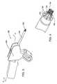
- FIG. 1is a perspective view of a first embodiment of an anastomosis device in a configuration prior to use with a graft vessel everted over the device;
- FIG. 2is a perspective view of the anastomosis device of FIG. 1 in a deployed configuration
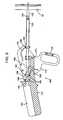
- FIG. 3is a perspective view of an anastomosis device deployment system
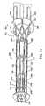
- FIG. 4is an enlarged perspective view of the distal end of the anastomosis device deployment system of FIG. 3 with an anastomosis device prior to deployment;
- FIG. 5is a side cross sectional view of the anastomosis device deployment system puncturing the target vessel to advance the anastomosis device into the target vessel wall;
- FIG. 6is a side cross sectional view of the anastomosis device deployment system advancing the anastomosis device into the target vessel wall;
- FIG. 7is a side cross sectional view of the anastomosis device deployment system with an expanded first annular flange
- FIG. 8is a side cross sectional view of the anastomosis device deployment system expanding a second annular flange
- FIG. 9is a schematic side cross-sectional view of a deployment tool taken along line A—A of FIG. 3, the deployment tool is shown during a vessel puncturing step;
- FIG. 10is a schematic side cross-sectional view of the deployment tool of FIG. 9 shown during an anastomosis device insertion step;
- FIG. 11is a schematic side cross-sectional view of the deployment tool of FIG. 9 shown during an anastomosis device expansion step;
- FIG. 12is a schematic side cross-sectional view of the deployment tool of FIG. 9 shown after the anastomosis device has been fully deployed;
- FIG. 13is a perspective view of a frangible anastomosis device in a configuration prior to use
- FIG. 14is a perspective view of the device shown in FIG. 13 after radial expansion thereof;
- FIG. 15shows a frangible link from the portion of FIG. 14 within the circle labeled A;
- FIG. 16shows the frangible link of FIG. 15 in a bent configuration
- FIG. 17shows a variation of the frangible link shown in FIG. 15;
- FIG. 18shows another variation of the frangible link shown in FIG. 15;
- FIG. 19shows a deforming crown design wherein the outer flange of the device is formed from frangible helical members
- FIG. 20shows a deforming crown design wherein the outer flange is formed from members which are mechanically attached to the tool
- FIG. 21shows how the members forming the outer flange are released from the deforming crown during formation of the outer flange
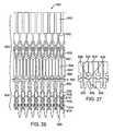
- FIG. 22shows (in planar form) a variation of the frangible anastomosis device shown in FIG. 13;
- FIG. 23shows details of a frangible link arrangement of the device shown in FIG. 22;
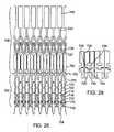
- FIG. 24shows (in planar form) a variation of the frangible anastomosis device shown in FIG. 13;
- FIG. 25shows details of a frangible link arrangement of the device shown in FIG. 24;
- FIG. 26shows (in planar form) a variation of the frangible anastomosis device shown in FIG. 13;
- FIG. 27shows details of a frangible link arrangement of the device shown in FIG. 26;
- FIG. 28shows (in planar form) a variation of the frangible anastomosis device shown in FIG. 13;
- FIG. 29shows details of a frangible link arrangement of the device shown in FIG. 28;
- FIGS. 30 and 31show details of a tissue anchoring arrangement
- FIG. 32shows details of how an anastomotic device in accordance with the invention can be deployed.
- FIGS. 33 and 34show a further embodiment of the anastomotic device.
- target vesselis thus used to refer to vessels within the patient which are connected to either or both of the upstream and downstream end of the graft vessel.
- a large vessel anastomotic deviceis used with large diameter target vessels such as the aorta or its major side branches or a small vessel anastomotic device is used for a target vessel which has a small diameter such as a coronary artery.
- the deviceIn deploying a large vessel anastomotic device, the device (with one end of a graft vessel attached thereto) is inserted into an incision in a wall of the target vessel with a deformable section in a first configuration, and the deformable section is radially expanded to a second configuration to deploy a flange.
- the flangeapplies an axial force against the wall of the target vessel.
- the flangecan be configured to apply a radial force, substantially transverse to the device longitudinal axis, against the wall of the target vessel, to secure the device to the target vessel.
- the devicecan have a plurality of deformable sections forming distal and proximal flanges. With the proximal and distal end flanges deployed, the device can be prevented from shifting proximally out of the target vessel or distally further into the interior of the target vessel.
- the large vessel devicescan be configured to connect to target vessels of various sizes having a wall thickness of at least about 0.5 mm, and typically about 0.5 mm to about 5 mm.
- the large vessel anastomotic deviceis configured to longitudinally collapse as the deformable section is radially expanded.
- the surgeoncan control the longitudinal collapse to thereby position the distal end flange at a desired location at least partially within the incision in the target vessel wall.
- the surgeoncan also control the position of the proximal end flange by longitudinally collapsing the device to a greater or lesser degree, to thereby position the proximal end flange at a desired location in contact with the target vessel.
- the devicecan be longitudinally collapsed to position the flanges against the target vessel wall and effectively connect the device thereto.
- This featureis significant because the device must be connected to target vessels which have a wide range of wall thickness.
- the aortic wall thicknessis typically about 1.4 mm to about 4.0 mm and the aorta diameter can range from about 25 to about 65 mm in diameter. Therefore, regardless of the thickness of the target vessel wall, the degree of deployment of the proximal end flange, and thus the longitudinal collapse of the device, can be controlled by the physician to thereby effectively connect the device to the target vessel.
- surgeonmay choose between partially deploying the proximal end flange so that it is positioned against an outer surface of the target vessel wall, or fully deploying the flange to position it in contact with the media of the target vessel wall within the incision in the target vessel wall.
- the devicecan be used on small target vessels having a wall thickness of less than about 1.0 mm, and typically about 0.1 mm to about 1 mm in the case of coronary arteries.
- the small vessel devicesprovide sutureless connection without significantly occluding the small inner lumen of the target vessel or impeding the blood flow therethrough.
- the small vessel devicescan include an outer flange (with the graft vessel connected thereto) loosely connected to an inner flange before insertion into the patient with the space between the loosely connected inner and outer flanges being at least as great as the wall thickness of the target vessel so that the inner flange can be inserted through an incision in the target vessel and into the target vessel lumen, with the outer flange outside the target vessel.
- the outer and inner flangesWith the outer and inner flanges in place on either side of a wall of the target vessel, tightening the flanges together compresses a surface of the graft vessel against the outer surface of the target vessel.
- This configurationforms a continuous channel between the graft vessel and the target vessel, without the need to suture the graft vessel to the target vessel wall and preferably without the use of hooks or barbs which puncture the target vessel.
- a large vessel devicecan be used to connect the proximal end of the graft vessel to the aorta
- a small vessel devicecan be used to connect the distal end of the graft vessel to an occluded coronary artery.
- the surgeonmay wish to avoid this region and connect the proximal end of the graft vessel to any other adjacent less diseased vessel, such as the arteries leading to the arms or head.
- the devicescan be used with venous grafts, such as a harvested saphenous vein graft, arterial grafts, such as a dissected mammary artery, or a synthetic prosthesis, as required.
- connection of the large vessel devicedoes not require the stoppage of blood flow in the target vessel.
- the anastomotic devicescan be connected to the target vessel without the use of cardiopulmonary bypass.
- anastomosis techniqueswherein the aorta is clamped to interrupt blood flow to the area of the aortic wall to which a vein is to be anastomosed may result in liberation of plaques and tissue fragments which can lead to organ dysfunction, such as strokes, renal failure, or intestinal ischemia.
- severely diseased aortasmay not provide an area suitable for clamping due to significant calcification of the aortic wall.
- the surgeondoes not need significant room inside the patient to connect the anastomotic devices to the target vessel.
- the anastomotic devicesallow the proximal end of the graft vessel to be connected to any part of the aorta. All parts of the aorta are accessible to the large vessel anastomosis devices, even when minimally invasive procedures are used. Consequently, the graft vessel may be connected to the descending aorta, so that the graft vessel would not be threatened by damage during a conventional sternotomy if a second operation is required at a later time.
- a sutureless connectioncan be provided between a graft and a target vessel, while minimizing thrombosis or restenosis associated with the anastomosis.
- the anastomotic devicescan be attached to the target vessel inside a patient remotely from outside the patient using specially designed applicators, so that the devices are particularly suitable for use in minimally invasive surgical procedures where access to the anastomosis site is limited.
- the devicesallow the anastomosis to be performed very rapidly, with high reproducibility and reliability, without clamping, and with or without the use of cardiopulmonary bypass.
- the surgeonoperates a deployment tool using both hands.
- One handsupports the tool via a handle while the other twists an actuation knob to deploy the anastomotic device.
- Locating the actuation knob on the tool's main axisminimizes the tendency of reaction forces to wobble the tool keeping it stable and in proper position during deployment.
- the twisting motionis converted to linear displacements by a set of rotating cams that engage a trocar, holder, and expander. The cams control the sequence of relative motions between the instrument's trocar and device deployment mechanisms.
- a surgeonwill place the tip of the instrument (the mechanical stop) in light contact with the site on the aorta to be anastomosed. Having located a suitable site, the surgeon then twists the actuation knob to fire the spring-loaded trocar and continues twisting to deploy the anastomotic device.
- the trocarpenetrates the aortic wall at a high rate of speed to minimize any unintended deformation of the aorta and maintains a substantially fluid-tight seal at the puncture site.
- the trocardilates as the anastomotic device and its holder tube (crown) are advanced through it, thus retracting the aortic tissue and serving as an introducer for the device.
- the trocaris withdrawn.
- the anastomotic deviceis then expanded to its full diameter and an inner flange is deployed.
- the deviceis then drawn outwards towards the instrument (mechanical stop) to seat the inner flange firmly against the intimal wall of the aorta.
- An outer flangeis then deployed from the external side, compressing the aortic wall between the inner and outer flanges and the device is disengaged from the instrument completing the anastomosis.
- FIG. 1illustrates the distal portion of an anastomosis device 10 according to a first embodiment of the present invention, the proximal portion (not shown) being adapted to be deployed by a deployment tool which will be explained later.
- the anastomosis device 10includes a plurality of axial members 12 and a plurality of struts 14 interconnecting the axial members.
- the axial members 12 and struts 14form a first linkage 16 at a first end of the device and a second linkage 18 at a second end of the device.
- the first and second linkages 16 , 18form inner and outer flanges 20 , 22 when the anastomosis device 10 is deployed as illustrated in FIG. 2 .
- the deployed flanges 20 , 22may be annular ring shaped or conical in shape.
- the first and second linkages 16 , 18are connected by a central connecting portion 24 .
- a graft vessel 30is inserted through a center of the tubular anastomosis device 10 and is everted over the first linkage 16 at the first end of the device.
- the first end of the devicemay puncture part way or all the way through the graft vessel wall to hold the graft vessel 30 on the device.
- An opening 34is formed in the target vessel 32 to receive the graft vessel 30 and anastomosis device 10 .
- the inner and outer flanges 20 , 22are formed as shown in FIG. 2 to secure the graft vessel to the target vessel by trapping the wall of the target vessel between the two flanges.
- the anastomosis device 10forms a smooth transition between the target vessel 32 and the graft vessel 30 which helps to prevent thrombi formation.
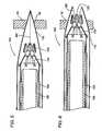
- the inner and outer flanges 20 , 22are formed by radial expansion of the anastomosis device 10 as follows.
- the first and second linkages 16 , 18are each made up of a plurality of axial members 12 and struts 14 .
- the struts 14are arranged in a plurality of diamond shapes with adjacent diamond shapes connected to each other to form a continuous ring of diamond shapes around the device.
- One axial member 12extends through a center of each of the diamond shapes formed by the struts 14 .
- a reduced thickness section 26 or hinge in each of the axial members 12provides a location for concentration of bending of the axial members.
- each of the diamond shaped linkages of struts 14are elongated in a circumferential direction causing a top and bottom of each of the diamond shapes to move closer together.
- the axial members 12bend along the reduced thickness sections 26 folding the ends of the device outward to form the inner and outer flanges 20 , 22 with the result that the wall of the target vessel 32 is trapped between the flanges and the everted graft vessel 30 is secured to the target vessel.
- the struts 14may be straight or curved members having constant or varying thicknesses.
- the axial members 12may have the reduced thickness sections 26 positioned at a center of each of the diamond shapes or off center inside the diamond shapes. The positioning and size of the reduced thickness sections 26 will determine the location of the flanges 20 , 22 and an angle the flanges make with an axis of the device when fully deployed.
- a final angle between the flanges 20 , 22 and longitudinal axis of the device 10is about 40-100 degrees, preferably about 50-90 degrees.
- FIGS. 3-7illustrate a deployment system 150 and sequence of deploying an anastomosis device 120 such as the device shown in FIGS. 1-2 with the deployment system.
- the deployment system 150includes a hollow outer trocar 152 (not shown in FIG. 3 ), a holder tube 154 positioned inside the trocar, and an expander tube 156 slidable inside the holder tube.
- the anastomosis device 120is attached to a distal end of the holder tube 154 by inserting T-shaped ends 112 of pull tabs 110 in slots 158 around the circumference of the holder tube.
- the trocar 152 , holder tube 154 , and expander tube 156are all slidable with respect to one another during operation of the device.
- a device handle 160is provided for moving the tubes with respect to one another will be described in further detail below with respect to FIGS. 8-11.
- the holder tube 154 , expander tube 156 , and the anastomosis device 120are positioned within the trocar 152 for insertion.
- the trocar 152has a hollow generally conical tip with a plurality of axial slots 162 which allow the conical tip to be spread apart so that the anastomosis device 120 can slide through the opened trocar.
- the trocar 152acting as a tissue retractor and guide, is inserted through the wall of the target vessel 32 forming an opening 34 .
- the anastomosis device 120is then advanced into or through the target vessel wall 32 with the holder tube 154 .
- the advancing of the holder tube 154causes the distal end of the trocar 152 to be forced to spread apart.
- the inner annular flange 20is deployed by advancing the expander tube 156 into the anastomosis device.
- the advancing of the expander tube 156increases the diameter of the anastomosis device 120 causing the inner flange to fold outward from the device. This expanding of the inner flange may be performed inside the vessel and then the device 120 may be drawn back until the inner flange abuts an interior of the target vessel wall 32 .
- the holder tube 154is advanced forming the outer flange.
- the anastomosis device 120drops into a radial groove 157 on an exterior of the expander tube 156 which holds the anastomosis device stationary on the expander tube 156 .
- the holder tube 154is then moved forward to detach the entire anastomosis device by disengaging the pull tabs 130 from the slots 158 in the holder tube and causing the outer flange to be deployed.
- shoulders 134 on the deviceshown most clearly in FIGS.
- the holder tube 154employs a plurality of flexible fingers which receive the pull tabs 130 of the anastomosis device 120 .
- each pull tab 130is received by an independent finger of the holder tube 154 .
- the flexible fingersflex outward bending the pull tabs 130 outward.
- the flexible fingerscan be designed to flex when the pull tabs and fingers are put under axial compression in which case the fingers and tabs buckle outwards together to deploy the outer flange and release the anastomosis device from the holder tube.
- FIGS. 9-12illustrate the operation of the handle 160 to move the trocar 152 , the holder tube 154 , and the expander tube 156 with respect to one another to deploy the anastomosis device 120 according to the present invention.
- the handle 160includes a grip 170 and a trigger 172 pivotally mounted to the grip at a pivot 174 .
- the trigger 172includes a finger loop 176 and three contoured cam slots 178 , 180 , 182 corresponding to the trocar 152 , holder tube 154 , and expander tube 156 , respectively.
- Each of these tubeshas a fitting 184 at a distal end thereof.
- a pin 186 connected to each of the fittings 184slides in a corresponding one of the cam slots 178 , 180 , 182 .
- a fourth cam slot and tubemay be added to control deployment of the outer flange.
- the handlecan be modified to include fewer cam slots for deployment of the inner and outer flanges.
- the handle 160is shown in FIG. 8 in an insertion position in which the trocar 152 extends beyond the holder tube 154 and the expander tube 156 for puncturing of the target vessel wall 32 .
- a flexible sealsuch as heat shrinkable plastic or elastomeric tubing can be provided on the outer surface of the trocar 152 such that the seal covers the axial slots 162 at a location spaced from the tip of the trocar to prevent leaking of blood from the target vessel after the incision is formed.
- the trocaris actuated by a mechanism which causes the trocar to penetrate the aorta wall at a high rate of speed to minimize deformation of the aorta and maintain a fluid tight seal at the puncture site in a manner similar to biopsy gun.
- the spring mechanism attached to the trocar and/or the handlecan be used to fire the trocar at the incision site. Any suitable actuating mechanism can be used to fire the trocar in accordance with the invention.
- the trigger 172is rotated from the position illustrated in FIG. 9 to the successive positions illustrated in FIGS. 10-12, the pins 186 slide in the cam slots 178 , 180 , 182 to move the trocar 152 , holder tube 154 and expander tube 156 .
- FIG. 10shows the handle 160 with the trigger 172 rotated approximately 30 degrees from the position of FIG. 9 .
- This rotationmoves the holder tube 154 and expander tube 156 forward into the wall of the target vessel 32 spreading the trocar 152 .
- the anastomosis device 120is now in position for deployment.
- FIG. 11shows the trigger 172 rotated approximately 45 degrees with respect to the position of FIG. 9 and the cam slot 182 has caused the expander tube 156 to be advanced within the holder tube 154 to deploy the inner flange.
- the trocar 152has also been withdrawn.
- FIG. 12shows the handle 160 with the trigger 172 pivoted approximately 60 degrees with respect to the position shown in FIG. 9 .
- the expander tube 156has been withdrawn to pull the inner flange against the vessel wall 32 and the holder tube 154 is moved forward to deploy the outer flange and disengage the holder tube 154 from the anastomosis device 120 .
- the handle 160also includes a first channel 188 and a second channel 190 in the grip 170 through which the graft vessel (not shown) may be guided.
- the grip 170also includes a cavity 192 for protecting an opposite end of the graft vessel from the attachment end.
- the anastomosis deviceincludes a frangible linkage which allows an implant to separate from the remainder of the device upon formation of the outer flange.
- the frangible linkagecan be radially expanded and axially compressed to fracture the frangible linkage.
- the inner flangecan be formed during radial expansion of the device and the implant can be severed while forming the outer flange.
- FIG. 13shows a device 200 which cooperates with a deployment tool 300 for delivering and deploying an implant 204 at a site in a living body.
- the deviceincludes a frangible linkage 202 connecting the implant 204 to a discard portion 206 .
- the implant 204can be expanded to deploy an inner flange and subsequently axially compressed to deploy an outer flange while severing the implant 204 from the discard portion 206 .
- the deployment toolcan then be withdrawn along with the discard portion 206 which remains attached to the distal end of the deployment tool 300 .
- FIG. 14shows the device 200 in the radially expanded condition but prior to being axially compressed.
- axially extending barbs 208(FIG. 13) are pivoted outwardly by struts 210 such that the outwardly extending barbs 208 and struts 210 form the inner flange.
- the barbs 208comprise points on the ends of axially extending members 212 which have narrow sections 214 located a desired distance from the free ends of the barbs 208 .
- the narrow sections 214can be located at axial positions along the device corresponding approximately to the axial midpoint of the struts 210 connecting adjacent members 212 when the device is in the pre-expanded condition shown in FIG. 13 .
- the distal ends of the strutscan be curved at their points of attachment to the members 212 .
- a curved bendcan be provided at the intersection where the proximal ends of the struts are attached together.
- the barbs 208are locked into position by an X-shaped frame formed by struts 210 and additional struts 216 .
- the struts 216are similar in configuration to the struts 210 with respect to how they are shaped and attached to the members 212 .
- Short axially extending members 218connect the intersection of the struts 210 to the intersection of the struts 216 .
- the frangible section 202is located at the proximal ends of axially extending members 220 which are connected to the members 212 by U-shaped links 222 .
- the members 220are arranged in pairs which are attached together at only their distal ends.
- the distal ends of the links 222are attached to proximal ends of the members 212 and the midpoint of each link 222 is attached to the distal ends of a respective pair of members 220 .
- the individual links 222are plastically deformed from their U-shaped configuration to form segments of a circumferentially extending annular ring.
- the devicebecomes shorter in the axial direction as links 222 form the annular ring and the distal ends of the members 220 move radially outward but not apart in the circumferential direction.
- the proximal ends of the members 220move radially outward and circumferentially apart.
- FIG. 15shows an expanded view of the circled portion A in FIG. 14 and FIG. 16 shows how the frangible section 202 can be bent to fracture connection points between members 220 and axial extending members 224 .
- proximal ends of the members 224are attached to U-shaped links 226 which allow the proximal ends of the members 224 to move radially outward but not circumferentially apart when the device is expanded.
- the distal ends of members 224and connected to the proximal ends of the members 220 by a frangible joint comprised of shearable connections 228 .
- the members 220are connected at their proximal ends by a cross piece 230 and the members 224 are connected at their distal ends by a cross piece 232 .
- the cross piece 230includes a recess 234 and the cross piece 232 includes a projection 236 located in the recess 234 .
- the frangible jointis preferably formed from a unitary piece of material (e.g., stainless steel, nickel titanium alloy, etc.) such as a laser cut tube wherein the shearable connections 228 comprise thin sections of material extending between opposite sides of the projection 236 and opposing walls of the recess 234 . As shown in FIG.
- the recess 234contains the projection 236 as the members 220 and 224 are pivoted about the joint formed by the shearable connections 228 .
- the shearable connections 228are fractured allowing the implant to separate from the discard portion of the device.
- the frangible link shown in FIGS. 15-16can be modified in various ways.
- the projectioncan have a slot 238 extending from the free end thereof towards cross piece 232 .
- the slot 238allows the portions of the projection on either side of the slot 238 to move closer together as the proximal ends of members 224 bend away from each other during radial expansion of the device 200 .
- the proximal ends of the members 220 on either side of the projection 236can move closer together as the distal ends of the members 220 move apart during the radial expansion.
- Another variationis shown in FIG.
- the device 200can be deployed using deployment tool 300 as follows.
- the device 200includes a crown 240 attached to a distal end 302 of the tool 300 .
- the crownincludes axially extending members 242 with tabs (not shown) on the proximal ends thereof, the members 242 being held in slots 304 of the tool 300 by the tabs.
- a plastic sleeve(not shown) can be placed over the slots 304 to prevent the members 242 from coming out of the slots.
- the crownis flared outwardly such that the members 242 are fully radially expanded at their proximal ends.
- the diamond shaped linkage of the crown 240is expanded from the configuration shown in FIG. 13 to the expanded configuration shown in FIG. 14 .
- the device 200is attached to the tool 300 in a manner such that the discard portion 206 stays with the tool during deployment of the implant 204 and removal of the tool from the implant site.
- the discardcan include tabbed members fitted in grooves of the tool.
- Other suitable attachment techniquesinclude welding the proximal end of the device to the tool using resistance welding, ultrasonic welding or the like, molding the proximal end of the device into the distal end of the tool such as by insert molding, mechanically fastening the proximal end of the device to the tool, adhesive bonding, etc.
- the deviceis deployed by radial expansion and axial compression.
- the axial compressioncan be accomplished by pushing the holder tube while the expander tube is held in a fixed position or vice versa.
- the axial compressioncan be accomplished by rotation of the device. For instance, FIG. 19, showing a buckling crown 240 a which includes helical members 244 extending from a ring 246 attached to the distal end 302 of the tool 300 . Additional helical members 248 which form the outer flange of the implant are connected to the helical members 244 by shearable connections 250 .
- the tool 300is rotated while preventing the implant 204 from rotating with the result that the helical members 244 and 248 bend outwardly at the location of the shearable connections 250 and form the outer flange.
- the shearable connections 250fracture releasing the implant 204 from the crown 240 a which remains attached to the tool.
- the crown 240 acan be attached to the tool in any desired manner, e.g. welding, molding, etc.
- the devicecan be designed so as to be released from the tool without use of fracture elements.
- the toolcan include a deforming crown which mechanically disengages with the device after forming the outer flange.
- the device and toolcan incorporate any suitable release mechanism which, for example, connects the crown to the deployment tool when a tensile force is applied to the connection but which disconnects when a compressive force is applied to the connection, e.g., hooks, tabs, spring clips, etc.
- FIG. 20shows an embodiment of a tool with a deforming crown 306 comprised of struts 308 and tabs 310 connected to the struts 308 by thin necks 312 .
- the device 200 ais similar to device 200 except that device 200 a does not include frangible links. Instead, device 200 a includes bendable members 252 which are bent outwardly by the deforming crown 306 to form the outer flange. As shown in FIG. 21, each of the members 252 includes a hole 254 sized larger than the tabs to allow the tabs to be released from the holes after the outer flange is formed.
- the tabs 310are fitted in the holes with the necks 312 received in the slots 256 .
- the struts 308can be shorter than the members 252 so that when the outer flange is formed the members 252 extend outwardly further than the struts 308 . As a result, the necks 312 slide out of the slots 256 and the tabs 310 slide out of the holes 254 as the outer flange is formed and the implant is released from the tool.
- FIG. 22shows a device 400 (illustrated in planar form for ease of description but which would be used in a tubular shape) which cooperates with a deployment tool (as described earlier) for delivering and deploying an implant 404 at a site in a living body.
- the deviceincludes a frangible linkage 402 connecting the implant 404 to a discard portion 406 .
- the implant 404can be expanded to deploy an inner flange and subsequently axially compressed to deploy an outer flange while severing the implant 404 from the discard portion 406 .
- the deployment toolcan then be withdrawn along with the discard portion 406 which remains attached to the distal end of the deployment tool.
- axially extending barbs 408are pivoted outwardly by struts 410 such that the outwardly extending barbs 408 and struts 410 form the inner flange.
- the barbs 408comprise points on the ends of axially extending members 412 which have narrow sections 414 located a desired distance from the free ends of the barbs 408 .
- the narrow sections 414can be located at axial positions along the device corresponding approximately to the axial midpoint of the struts 410 connecting adjacent members 412 when the device is in the pre-expanded condition.
- the distal ends of the strutscan be curved at their points of attachment to the members 412 .
- a curved bendcan be provided at the intersection where the proximal ends of the struts are attached together.
- the barbs 408are locked into position by an X-shaped frame formed by struts 410 and additional struts 416 .
- the struts 416are similar in configuration to the struts 410 with respect to how they are shaped and attached to the members 412 .
- Short axially extending members 418connect the intersection of the struts 410 to the intersection of the struts 416 .
- the frangible section 402is located at the proximal ends of axially extending members 420 which are connected to the members 412 by U-shaped links 422 .
- the members 420are arranged in pairs which are attached together at midpoints of links 422 .
- the individual links 422are plastically deformed from their U-shaped configuration to form segments of a circumferentially extending annular ring.
- the devicebecomes shorter in the axial direction as links 422 form the annular ring and the distal ends of the pairs of members 420 attached to an individual link 422 move radially outward but not apart in the circumferential direction.
- the proximal ends of the members 420move radially outward and circumferentially apart.
- the frangible section 402is located between axial members 420 and axially extending members 424 . As shown in FIG. 22, the members 420 are closer together at their distal ends and this condition remains after expansion of the device.
- the proximal ends of the members 424are attached to mid-points of U-shaped links 426 by a pair of short and closely spaced apart axially extending links 427 .
- the distal ends of members 424are connected to the proximal ends of the members 420 by a frangible joint comprised of shearable connections 402 which operate in a manner similar to the previously discussed connections 228 , i.e., as shown in FIG.
- the members 420are connected at their proximal ends by a cross piece 430 and the members 424 include a projection 436 received in a recess 434 .
- the frangible jointis formed from a unitary piece of material such as a laser cut tube wherein the shearable connections 402 comprise thin sections of material extending between opposite sides of the projection 436 and opposing walls of the recess 434 .
- the device 400can be deployed in the same manner that the device 200 is deployed using deployment tool 300 . That is, the device 400 includes a crown attached to a distal end of the deployment tool.
- the crownincludes axially extending members 442 with tabs 443 on the proximal ends thereof, the members 442 being held in slots 304 of the tool 300 by the tabs 443 .
- a plastic sleeve(not shown) can be placed over the slots 304 to prevent the members 442 from coming out of the slots.
- the crownWhen mounted on the deployment tool, the crown is flared outwardly such that the members 442 are fully radially expanded at their proximal ends.
- the diamond shaped linkage of the crown 440is expanded from an unexpanded condition like the configuration shown in FIG. 13 to an expanded condition like the expanded configuration shown in FIG. 14 .
- FIG. 24shows a device 500 (illustrated in planar form for ease of description but which would be used in a tubular shape) which cooperates with a deployment tool (as described earlier) for delivering and deploying an implant 504 at a site in a living body.
- the deviceincludes a frangible linkage 502 connecting the implant 504 to a discard portion 506 .
- the implant 504can be expanded to deploy an inner flange and subsequently axially compressed to deploy an outer flange while severing the implant 504 from the discard portion 506 .
- the deployment toolcan then be withdrawn along with the discard portion 506 which remains attached to the distal end of the deployment tool.
- the barbs 508are pivoted outwardly by struts 510 such that the outwardly extending barbs 508 and struts 510 form the inner flange.
- the barbs 508comprise points on the ends of axially extending members 512 which have narrow sections 514 located a desired distance from the free ends of the barbs 508 .
- the narrow sections 514can be located at axial positions along the device corresponding approximately to the axial midpoint of the struts 510 connecting adjacent members 512 when the device is in the pre-expanded condition.
- the distal ends of the strutscan be curved at their points of attachment to the members 512 .
- a curved bendcan be provided at the intersection where the proximal ends of the struts are attached together.
- the barbs 508are locked into position by an X-shaped frame formed by struts 510 and additional struts 516 .
- the struts 516are similar in configuration to the struts 510 with respect to how they are shaped and attached to the members 512 .
- Short axially extending members 518connect the intersection of the struts 510 to the intersection of the struts 516 .
- the frangible section 502is located at the proximal ends of axially extending members 520 which are connected to the members 512 by U-shaped links 522 .
- the members 520are arranged in pairs which are attached together at only their distal ends.
- the distal ends of the links 522are attached to proximal ends of the members 512 and the midpoint of each link 522 is attached to the distal ends of a respective pair of members 520 .
- the individual links 522are plastically deformed from their U-shaped configuration to form segments of a circumferentially extending annular ring.
- the devicebecomes shorter in the axial direction as links 522 form the annular ring and the distal ends of the members 520 move radially outward but not apart in the circumferential direction.
- the proximal ends of the members 520move radially outward and circumferentially apart.
- the frangible section 502is located between pairs of the axial members 520 and pairs of axially extending members 524 . As shown in FIG. 24, each pair of members 520 attached to an individual link 522 are closer together at their distal ends and this condition remains when the device is expanded.
- the proximal ends of pairs of the members 524are attached at locations intermediate mid-points and ends of U-shaped links 526 by a pair of curved links 527 .
- the U-shaped links 526deform into a circumferentially extending ring and cause the proximal ends of the members 524 to spread apart such that a gap 528 between the members 524 becomes wider at the proximal ends of the members 524 .
- the membersinclude a curved recess 529 at the distal ends thereof.
- the distal ends of members 524are connected to the proximal ends of the members 520 by a frangible joint comprised of shearable connections 502 which operate in a manner similar to the previously discussed connections 228 , i.e., as shown in FIG. 25, the members 520 are connected at their proximal ends by a cross piece 530 and the members 524 are connected by a cross piece 535 which includes a projection 536 received in a recess 534 .
- the frangible jointis formed from a unitary piece of material such as a laser cut tube wherein the shearable connections 502 comprise thin sections of material extending between opposite sides of the projection 536 and opposing walls of the recess 534 .
- the shearable connections 502are fractured allowing the implant to separate from the discard portion of the device.
- the device 500can be deployed in the same manner that the device 200 is deployed using deployment tool 300 . That is, the device 500 includes a crown attached to a distal end of the deployment tool.
- the crownincludes axially extending members 542 with tabs 543 on the proximal ends thereof, the members 542 being held in slots 304 of the tool 300 by the tabs 543 .
- a plastic sleeve(not shown) can be placed over the slots 304 to prevent the members 542 from coming out of the slots.
- the crownWhen mounted on the deployment tool, the crown is flared outwardly such that the members 542 are fully radially expanded at their proximal ends.
- the diamond shaped linkage of the crown 540is expanded from an unexpanded condition like the configuration shown in FIG. 13 to an expanded condition like the expanded configuration shown in FIG. 14 .
- FIG. 26shows a device 600 (illustrated in planar form for ease of description but which would be used in a tubular shape) which cooperates with a deployment tool (as described earlier) for delivering and deploying an implant 604 at a site in a living body.
- the deviceincludes a frangible linkage 602 connecting the implant 604 to a discard portion 606 .
- the implant 604can be expanded to deploy an inner flange and subsequently axially compressed to deploy an outer flange while severing the implant 604 from the discard portion 606 .
- the deployment toolcan then be withdrawn along with the discard portion 606 which remains attached to the distal end of the deployment tool.
- the barbs 608are pivoted outwardly by struts 610 such that the outwardly extending barbs 608 and struts 610 form the inner flange.
- the barbs 608comprise points on the ends of axially extending members 612 which have narrow sections 614 located a desired distance from the free ends of the barbs 608 .
- the narrow sections 614can be located at axial positions along the device corresponding approximately to a position slightly distal of the axial midpoint of the struts 610 connecting adjacent members 612 when the device is in the pre-expanded condition.
- the distal ends of the strutscan be curved at their points of attachment to the members 612 .
- a curved bendcan be provided at the intersection where the proximal ends of the struts are attached together.
- the barbs 608are locked into position by an X-shaped frame formed by struts 610 and additional struts 616 .
- the struts 616are similar in configuration to the struts 610 with respect to how they are shaped and attached to the members 612 .
- Short axially extending members 618connect the intersection of the struts 610 to the intersection of the struts 616 .
- the frangible section 602is located at the proximal ends of axially extending members 620 which are connected to the members 612 by U-shaped links 622 .
- the members 620are arranged as circumferentially spaced apart pairs which are attached together at midpoints of links 622 .
- the individual links 622are plastically deformed from their U-shaped configuration to form segments of a circumferentially extending annular ring.
- the devicebecomes shorter in the axial direction as links 622 form the annular ring.
- the proximal ends of each pair of members 620 attached to an individual link 622move radially outward and apart in the circumferential direction.
- the frangible section 602is located between pairs of the axial members 620 and pairs of axially extending members 624 .
- the members 620are substantially parallel to each other when the device is in its unexpanded condition, i.e., prior to formation of the inner flange. However, when the device is radially expanded the distal ends of the members 620 will remain closer together than their proximal ends since the distal ends are attached to a midpoint of the links 622 .
- the proximal ends of pairs of the members 624are attached at mid-points of U-shaped links 626 by a pair of thin links 627 .
- the U-shaped links 626deform into a circumferentially extending ring while proximal ends of pairs of the members 624 spread apart such that a gap 628 between the pairs of members 624 becomes wider at the proximal ends of the members 624 .
- the members 624include a curved recess 629 at the distal ends thereof.
- the distal ends of members 624are connected to the proximal ends of the members 620 by a frangible joint comprised of shearable connections 602 which operate in a manner similar to the previously discussed connections 228 , i.e., as shown in FIG.
- the members 620are connected at their proximal ends by a cross piece 630 and the members 624 are connected by a cross piece 635 which includes a projection 636 received in a recess 634 .
- the frangible jointis formed from a unitary piece of material such as a laser cut tube wherein the shearable connections 602 comprise thin sections of material extending between opposite sides of the projection 636 and opposing walls of the recess 634 .
- the device 600can be deployed in the same manner that the device 200 is deployed using deployment tool 300 . That is, the device 600 includes a crown attached to a distal end of the deployment tool.
- the crownincludes axially extending members 642 with tabs 643 on the proximal ends thereof, the members 642 being held in slots 304 of the tool 300 by the tabs 643 .
- a plastic sleeve(not shown) can be placed over the slots 304 to prevent the members 642 from coming out of the slots.
- the crownWhen mounted on the deployment tool, the crown is flared outwardly such that the members 642 are fully radially expanded at their proximal ends.
- the diamond shaped linkage of the crown 640is expanded from an unexpanded condition like the configuration shown in FIG. 13 to an expanded condition like the expanded configuration shown in FIG. 14 .
- FIG. 24shows a device 700 (illustrated in planar form for ease of description but which would be used in a tubular shape) which cooperates with a deployment tool (as described earlier) for delivering and deploying an implant 704 at a site in a living body.
- the deviceincludes a frangible linkage 702 connecting the implant 704 to a discard portion 706 .
- the implant 704can be expanded to deploy an inner flange and subsequently axially compressed to deploy an outer flange while severing the implant 704 from the discard portion 706 .
- the deployment toolcan then be withdrawn along with the discard portion 706 which remains attached to the distal end of the deployment tool.
- axially extending barbs 708are pivoted outwardly by struts 710 such that the outwardly extending barbs 708 and struts 710 form the inner flange.
- the barbs 708comprise points on the ends of axially extending members 712 which have narrow sections 714 located a desired distance from the free ends of the barbs 708 .
- the narrow sections 714can be located at axial positions along the device corresponding approximately to the axial midpoint of the struts 710 connecting adjacent members 712 when the device is in the pre-expanded condition.
- the distal ends of the strutscan be curved at their points of attachment to the members 712 .
- a curved bendcan be provided at the intersection where the proximal ends of the struts are attached together.
- the barbs 708are locked into position by an X-shaped frame formed by struts 710 and additional struts 716 .
- the struts 716are similar in configuration to the struts 710 with respect to how they are shaped and attached to the members 712 .
- Short axially extending members 718connect the intersection of the struts 710 to the intersection of the struts 716 .
- the frangible section 702is located at the proximal ends of axially extending members 720 which are connected to the members 712 by U-shaped links 722 and U-shaped links 723 .
- the members 720are arranged in pairs which are attached at their distal ends to proximal ends of the links 723 and the midpoints of the links 723 are attached to midpoints of the links 722 .
- the ends of the links 722are attached to the proximal ends of adjacent members 718 .
- the individual links 722 , 723are plastically deformed from their U-shaped configuration to form segments of two circumferentially extending annular rings.
- the devicebecomes shorter in the axial direction as links 722 , 723 form the annular rings and the distal ends of each pair of the members 720 attached to an individual link 723 move radially outward but not apart in the circumferential direction.
- the proximal ends of pairs of the members 720move radially outward and circumferentially apart.
- the frangible section 702is located between pairs of the axial members 720 and pairs of axially extending members 724 .
- the members 720 attached to an individual link 722are somewhat closer together at their distal ends than their proximal ends, a condition which remains after expansion of the device.
- the proximal ends of pairs of the members 724are attached to mid-points of U-shaped links 726 by a pair of short links 727 .
- the U-shaped links 726deform into a circumferentially extending ring and cause the proximal ends of the members 724 to spread apart such that a gap 728 between the members 724 becomes wider at the proximal ends of the members 724 .
- the membersinclude a curved recess 729 at the distal ends thereof.
- the distal ends of members 724are connected to the proximal ends of the members 720 by a frangible joint comprised of shearable connections 702 which operate in a manner similar to the previously discussed connections 228 , i.e., as shown in FIG. 29, the members 720 are connected at their proximal ends by a cross piece 730 and the members 724 are connected by a cross piece 735 which includes a projection 736 received in a recess 734 .
- the frangible jointis formed from a unitary piece of material such as a laser cut tube wherein the shearable connections 702 comprise thin sections of material extending between opposite sides of the projection 736 and opposing walls of the recess 734 .
- the shearable connections 702are fractured allowing the implant to separate from the discard portion of the device.
- the device 700can be deployed in the same manner that the device 200 is deployed using deployment tool 300 . That is, the device 700 includes a crown attached to a distal end of the deployment tool.
- the crownincludes axially extending members 742 with tabs 743 on the proximal ends thereof, the members 742 being held in slots 304 of the tool 300 by the tabs 743 .
- a plastic sleeve(not shown) can be placed over the slots 304 to prevent the members 742 from coming out of the slots.
- the crownWhen mounted on the deployment tool, the crown is flared outwardly such that the members 742 are fully radially expanded at their proximal ends.
- the diamond shaped linkage of the crown 740is expanded from an unexpanded condition like the configuration shown in FIG. 13 to an expanded condition like the expanded configuration shown in FIG. 14 .
- FIGS. 30 and 31show details of a tissue anchoring arrangement which can optionally be incorporated in the anastomosis device according to the invention.
- FIG. 30shows a distal end of a device 800 (illustrated in planar form for ease of description but which would be used in a tubular shape) wherein axially extending members 802 having points 804 for penetrating the graft vessel (as described earlier) also include a tissue anchoring arrangement 806 .
- the tissue anchoring arrangement 806comprises one or more projections (e.g., tangs or barbs) extending from one or both sides of the members 802 , the projections providing anchor points against the inner surface 810 of the target vessel 812 , as shown in FIG.
- the projections 806can include points 808 which embed themselves in the tissue of the target vessel with or without penetrating the tissue. It is desirable that the projections provide enough of an anchoring effect to prevent sudden increases in blood pressure in the target vessel (after the anastomosis operation) from rupturing the seal between the graft vessel and the target vessel created by the anastomosis device.
- the outer flangecan also include anchoring projections which can be used in lieu of or addition to anchoring projections on the inner flange.
- FIG. 32A preferred method of loading an expander 156 in a holder tube 154 and placing a graft vessel over the anastomosis device is explained with reference to FIG. 32, wherein expander 156 has been inserted in holder tube 154 .
- the barbed ends 824 of device 820preferably are bent outwardly so as to form an angle such as 5 to 60° to the central axis of the device.
- the expander 156can be advanced within the holder tube 154 to a location at which a proximal portion 822 of anastomosis device 820 is expanded over the expander.
- the barbed ends 824can be rotated inwardly somewhat to form a smaller angle with the central axis of the device 820 . Then, after a graft vessel is threaded through the anastomosis device 820 , the end of the graft vessel can be everted over the distal end of the anastomosis device and the barbed ends 824 can be poked through the graft vessel. Details of how this eversion process can be carried out are set forth in commonly assigned U.S. patent application Ser. No. 09/440,166 filed on Nov. 15, 1999.
- the holder tube 154can be loaded in a trocar (not shown). Details of preferred trocar designs and an explanation of how the trocar creates an incision in a target vessel can be found in commonly assigned U.S. patent application Ser. No. 09/440,263 (filed Nov. 15, 1999).
- the inner flangecan be expanded by pushing the expander 156 a set distance while maintaining the holder tube 154 in a fixed position.
- the linkage of the inner flangerotates the barbed ends 824 about the hinged connections 828 such that the barbed ends 824 from an angle of 40 to 140° with the central axis.
- the holder tube 154is pushed a set distance while holding the expander 156 in a fixed position to deploy the outer flange.
- the linkage of the outer flange and the discard portion of the anastomosis deviceis axially compressed such that the linkage fractures as the outer flange is rotated outwardly and towards the already deployed inner flange.
- Each of the anastomosis devices described aboveare preferably single piece devices which are formed by laser cutting or punching from a tube or sheet of material.
- the devicesmay be provided in varying sizes to join vessels such as arteries, veins, bile ducts, etc., of different sizes.
- various linkage arrangementshave been shown wherein the devices include struts which extend between two circumferentially spaced apart locations and axial members which extend between two axially spaced apart locations, the linkages which form the flanges could also be formed by V-shaped links arranged in diamond like patterns.
- FIG. 33shows an example of a tubular mesh 830 which can be axially compressed to form an outwardly extending flange.
- the mesh 830includes short links 832 and 838 and long links 834 and 836 , the links 832 and 834 being joined to form a first diamond shaped pattern, the links 834 and 836 being joined to form a second diamond shaped pattern, and the links 836 and 838 being joined to form a third diamond shaped pattern.
- axial compression of the tubular mesh 830will cause the links 834 and 836 to pivot about joints 835 connecting the links 834 to the links 836 and thus form a flange as illustrated in FIG. 34 .
- the mesh 830can be joined to another mesh with the same or different linkage arrangement with or without a connecting linkage therebetween. If the same linkage arrangement is used, in order to obtain deployment of one flange prior to deployment of the other flange, one of the linkages can be made with wider and/or thicker links. For example, by using a distal linkage of thin links and a proximal linkage of thick links, it is possible to deploy the inner flange prior to deployment of the outer flange. In other words, axial compression of the tubular mesh can cause the weaker distal linkage to deploy first and form the inner flange after which the outer flange can be formed by axial compression of the stronger proximal linkage.
- the anastomosis devices of the present inventionmay be used in other types of anastomosis procedures.
- the anastomosis devicemay be used in femoral—femoral bypass, vascular shunts, subclavian-carotid bypass, organ transplants, and the like.
- the anastomosis devicesmay be made of any known material which can be bent and will retain the bent shape such as stainless steel, nickel titanium alloys, and the like.
- the hinges or pivot jointswhich have been discussed above in the various embodiments of the present invention may be designed to concentrate the bending at a desired location.
Landscapes
- Health & Medical Sciences (AREA)
- Life Sciences & Earth Sciences (AREA)
- Surgery (AREA)
- General Health & Medical Sciences (AREA)
- Public Health (AREA)
- Biomedical Technology (AREA)
- Heart & Thoracic Surgery (AREA)
- Veterinary Medicine (AREA)
- Engineering & Computer Science (AREA)
- Animal Behavior & Ethology (AREA)
- Molecular Biology (AREA)
- Nuclear Medicine, Radiotherapy & Molecular Imaging (AREA)
- Medical Informatics (AREA)
- Gastroenterology & Hepatology (AREA)
- Pulmonology (AREA)
- Cardiology (AREA)
- Oral & Maxillofacial Surgery (AREA)
- Transplantation (AREA)
- Vascular Medicine (AREA)
- Surgical Instruments (AREA)
- Prostheses (AREA)
Abstract
Description
Claims (28)
Priority Applications (3)
| Application Number | Priority Date | Filing Date | Title |
|---|---|---|---|
| US10/003,406US6537288B2 (en) | 1999-05-18 | 2001-12-06 | Implantable medical device such as an anastomosis device |
| US10/273,910US7048751B2 (en) | 2001-12-06 | 2002-10-18 | Implantable medical device such as an anastomosis device |
| US11/437,443US20060212054A1 (en) | 1999-05-18 | 2006-05-19 | Anastomosis device with separable section |
Applications Claiming Priority (3)
| Application Number | Priority Date | Filing Date | Title |
|---|---|---|---|
| US09/314,278US6428550B1 (en) | 1999-05-18 | 1999-05-18 | Sutureless closure and deployment system for connecting blood vessels |
| US09/437,428US6419681B1 (en) | 1999-05-18 | 1999-11-15 | Implantable medical device such as an anastomosis device |
| US10/003,406US6537288B2 (en) | 1999-05-18 | 2001-12-06 | Implantable medical device such as an anastomosis device |
Related Parent Applications (1)
| Application Number | Title | Priority Date | Filing Date |
|---|---|---|---|
| US09/437,428ContinuationUS6419681B1 (en) | 1999-05-18 | 1999-11-15 | Implantable medical device such as an anastomosis device |
Related Child Applications (1)
| Application Number | Title | Priority Date | Filing Date |
|---|---|---|---|
| US10/273,910ContinuationUS7048751B2 (en) | 1999-05-18 | 2002-10-18 | Implantable medical device such as an anastomosis device |
Publications (2)
| Publication Number | Publication Date |
|---|---|
| US20020042622A1 US20020042622A1 (en) | 2002-04-11 |
| US6537288B2true US6537288B2 (en) | 2003-03-25 |
Family
ID=26979294
Family Applications (1)
| Application Number | Title | Priority Date | Filing Date |
|---|---|---|---|
| US10/003,406Expired - LifetimeUS6537288B2 (en) | 1999-05-18 | 2001-12-06 | Implantable medical device such as an anastomosis device |
Country Status (3)
| Country | Link |
|---|---|
| US (1) | US6537288B2 (en) |
| AU (1) | AU5143000A (en) |
| WO (1) | WO2000069364A2 (en) |
Cited By (124)
| Publication number | Priority date | Publication date | Assignee | Title |
|---|---|---|---|---|
| US20020169466A1 (en)* | 2001-05-14 | 2002-11-14 | St. Jude Medical Atg, Inc. | Medical grafting methods and apparatus |
| US20030088256A1 (en)* | 2001-10-03 | 2003-05-08 | Conston Stanley R. | Devices and methods for interconnecting vessels |
| US20030100920A1 (en)* | 1999-07-28 | 2003-05-29 | Akin Jodi J. | Devices and methods for interconnecting conduits and closing openings in tissue |
| US20030191481A1 (en)* | 2000-03-31 | 2003-10-09 | John Nguyen | Multiple bias surgical fastener |
| US20030208214A1 (en)* | 2000-03-20 | 2003-11-06 | Amir Loshakove | Anastomotic connector and graft expander for mounting a graft |
| US20030212418A1 (en)* | 2000-10-12 | 2003-11-13 | Cardica, Inc. | Implantable superelastic anastomosis device |
| US20040002721A1 (en)* | 1999-09-01 | 2004-01-01 | Podmore Jonathan L. | Method and apparatus for performing end-to-end and end-to-side anastomosis with eversion of tissue edges |
| US20040049221A1 (en)* | 1998-05-29 | 2004-03-11 | By-Pass, Inc. | Method and apparatus for forming apertures in blood vessels |
| US20040054303A1 (en)* | 2002-07-29 | 2004-03-18 | Taylor Geoffrey L. | Blanching response pressure sore detector apparatus and method |
| US6719781B1 (en)* | 1996-06-14 | 2004-04-13 | Aptus Medical Inc. | Catheter apparatus having an improved shape-memory alloy cuff and inflatable on-demand balloon for creating a bypass graft in-vivo |
| US20040073247A1 (en)* | 1998-05-29 | 2004-04-15 | By-Pass, Inc. | Method and apparatus for forming apertures in blood vessels |
| US20040087985A1 (en)* | 1999-03-19 | 2004-05-06 | Amir Loshakove | Graft and connector delivery |
| US20040097988A1 (en)* | 1999-01-15 | 2004-05-20 | Ventrica, Inc. | Methods and devices for placing a conduit in fluid communication with a target vessel |
| US20040097973A1 (en)* | 2000-03-20 | 2004-05-20 | Amir Loshakove | Transvascular bybass method and system |
| US20040168691A1 (en)* | 1998-02-13 | 2004-09-02 | Sharkawy A. Adam | Conduits for use in placing a target vessel in fluid communication with source of blood |
| US20050027308A1 (en)* | 2001-02-27 | 2005-02-03 | Davis John W. | Methods for performing anastomosis |
| US20050038457A1 (en)* | 2002-01-22 | 2005-02-17 | Cardica, Inc. | Tool for deploying an anastomosis device |
| US20050043781A1 (en)* | 1998-02-13 | 2005-02-24 | Mark Foley | Methods and devices providing transmyocardial blood flow to the arterial vascular system of the heart |
| US20050101983A1 (en)* | 1998-05-29 | 2005-05-12 | By-Pass,Inc. | Method and apparatus for forming apertures in blood vessels |
| US20050143758A1 (en)* | 2003-12-24 | 2005-06-30 | Ryan Abbott | Anastomosis device, tools and methods of using |
| US20050143764A1 (en)* | 1997-04-23 | 2005-06-30 | St. Jude Medical Atg, Inc. | Medical grafting connectors and fasteners |
| US20050149071A1 (en)* | 2003-12-24 | 2005-07-07 | Ryan Abbott | Anastomosis device, tools and method of using |
| US20050165426A1 (en)* | 2002-06-19 | 2005-07-28 | Scott Manzo | Method and apparatus for anastomosis including annular joining member |
| US20050283173A1 (en)* | 2004-06-17 | 2005-12-22 | Abbott Ryan C | Angled anastomosis device, tools and method of using |
| US6979338B1 (en) | 1998-05-29 | 2005-12-27 | By-Pass Inc. | Low profile anastomosis connector |
| US20060020270A1 (en)* | 2003-01-30 | 2006-01-26 | Ronald Jabba | Clip applier and methods of use |
| US20060030869A1 (en)* | 2002-11-14 | 2006-02-09 | By-Pass, Inc. | Adhesive anastomosis connection system |
| US7022131B1 (en) | 1998-05-29 | 2006-04-04 | By-Pass Inc. | Methods and devices for vascular surgery |
| US7063711B1 (en) | 1998-05-29 | 2006-06-20 | By-Pass, Inc. | Vascular surgery |
| US20060135989A1 (en)* | 2000-12-07 | 2006-06-22 | Carley Michael T | Closure device |
| US20070010835A1 (en)* | 2003-08-22 | 2007-01-11 | Tom Breton | Eversion apparatus and methods |
| US7182771B1 (en)* | 2001-12-20 | 2007-02-27 | Russell A. Houser | Vascular couplers, techniques, methods, and accessories |
| US20070055344A1 (en)* | 1998-02-13 | 2007-03-08 | Gittings Darin C | Devices and methods for use in performing transmyocardial coronary bypass |
| US7258694B1 (en) | 2002-06-17 | 2007-08-21 | Origin Medsystems, Inc. | Medical punch and surgical procedure |
| US20070233225A1 (en)* | 1998-02-13 | 2007-10-04 | Rapacki Alan R | Delivering a conduit into a heart wall to place a coronary vessel in communication with a heart chamber and removing tissue from the vessel or heart wall to facilitate such communication |
| US20070290497A1 (en)* | 2006-06-15 | 2007-12-20 | Arendt Albert L | Children's ride-on vehicles with reconfigured bodies and methods for forming the same |
| US20080018016A1 (en)* | 1999-09-10 | 2008-01-24 | Rapacki Alan R | Manufacturing conduits for use in placing a target vessel in fluid communication with a source of blood |
| US7351247B2 (en) | 2002-09-04 | 2008-04-01 | Bioconnect Systems, Inc. | Devices and methods for interconnecting body conduits |
| US20080147114A1 (en)* | 1998-05-29 | 2008-06-19 | Bypass, Inc. | Vascular port device |
| US20080171101A1 (en)* | 1999-09-10 | 2008-07-17 | Rapacki Alan R | Manufacturing conduits for use in placing a target vessel in fluid communication with a source of blood |
| US20080269784A1 (en)* | 2003-12-24 | 2008-10-30 | Ryan Abbott | Anastomosis device, tools and methods of using |
| US20080269628A1 (en)* | 2007-04-25 | 2008-10-30 | Siemens Medical Solutions Usa, Inc. | Denoising and Artifact Rejection for Cardiac Signal in a Sensis System |
| US20090036817A1 (en)* | 2007-08-02 | 2009-02-05 | Bio Connect Systems | Implantable flow connector |
| US20090105713A1 (en)* | 2007-10-09 | 2009-04-23 | William Cook, Europe Aps | Deployment handle for an implant deployment device |
| US20090131826A1 (en)* | 2006-02-24 | 2009-05-21 | Boston Scientific Scimed, Inc. | Obtaining a tissue sample |
| US7547313B2 (en) | 1998-06-03 | 2009-06-16 | Medtronic, Inc. | Tissue connector apparatus and methods |
| USD611144S1 (en) | 2006-06-28 | 2010-03-02 | Abbott Laboratories | Apparatus for delivering a closure element |
| US7722643B2 (en) | 1999-03-01 | 2010-05-25 | Medtronic, Inc. | Tissue connector apparatus and methods |
| US7744611B2 (en) | 2000-10-10 | 2010-06-29 | Medtronic, Inc. | Minimally invasive valve repair procedure and apparatus |
| US7763040B2 (en) | 1998-06-03 | 2010-07-27 | Medtronic, Inc. | Tissue connector apparatus and methods |
| US7806910B2 (en) | 2002-11-26 | 2010-10-05 | Abbott Laboratories | Multi-element biased suture clip |
| US7819895B2 (en) | 2000-01-05 | 2010-10-26 | Integrated Vascular Systems, Inc. | Vascular sheath with bioabsorbable puncture site closure apparatus and methods of use |
| US7828817B2 (en) | 2000-01-05 | 2010-11-09 | Integrated Vascular Systems, Inc. | Apparatus and methods for delivering a closure device |
| US7841502B2 (en) | 2007-12-18 | 2010-11-30 | Abbott Laboratories | Modular clip applier |
| US7842068B2 (en) | 2000-12-07 | 2010-11-30 | Integrated Vascular Systems, Inc. | Apparatus and methods for providing tactile feedback while delivering a closure device |
| US7850709B2 (en) | 2002-06-04 | 2010-12-14 | Abbott Vascular Inc. | Blood vessel closure clip and delivery device |
| US7850797B2 (en) | 2002-12-31 | 2010-12-14 | Integrated Vascular Systems, Inc. | Methods for manufacturing a clip and clip |
| US7867249B2 (en) | 2003-01-30 | 2011-01-11 | Integrated Vascular Systems, Inc. | Clip applier and methods of use |
| US20110015532A1 (en)* | 2007-04-25 | 2011-01-20 | Siemens Medical Solutions Usa, Inc. | Denoising and Artifact Rejection For Cardiac Signal in a Sensis System |
| US7879047B2 (en) | 2003-12-10 | 2011-02-01 | Medtronic, Inc. | Surgical connection apparatus and methods |
| US7879071B2 (en) | 2000-12-07 | 2011-02-01 | Integrated Vascular Systems, Inc. | Closure device and methods for making and using them |
| US7887563B2 (en) | 2001-06-07 | 2011-02-15 | Abbott Vascular Inc. | Surgical staple |
| US7931669B2 (en) | 2000-01-05 | 2011-04-26 | Integrated Vascular Systems, Inc. | Integrated vascular device with puncture site closure component and sealant and methods of use |
| US7938840B2 (en) | 1999-04-05 | 2011-05-10 | Medtronic, Inc. | Apparatus and methods for anastomosis |
| US7963973B2 (en) | 1998-06-03 | 2011-06-21 | Medtronic, Inc. | Multiple loop tissue connector apparatus and methods |
| US7976556B2 (en) | 2002-09-12 | 2011-07-12 | Medtronic, Inc. | Anastomosis apparatus and methods |
| US8007512B2 (en) | 2002-02-21 | 2011-08-30 | Integrated Vascular Systems, Inc. | Plunger apparatus and methods for delivering a closure device |
| US8048108B2 (en) | 2005-08-24 | 2011-11-01 | Abbott Vascular Inc. | Vascular closure methods and apparatuses |
| US8105345B2 (en) | 2002-10-04 | 2012-01-31 | Medtronic, Inc. | Anastomosis apparatus and methods |
| US8118822B2 (en) | 1999-03-01 | 2012-02-21 | Medtronic, Inc. | Bridge clip tissue connector apparatus and methods |
| US8177836B2 (en) | 2008-03-10 | 2012-05-15 | Medtronic, Inc. | Apparatus and methods for minimally invasive valve repair |
| US20120123454A1 (en)* | 2010-11-11 | 2012-05-17 | Wilson T. Asfora | Sutureless vascular anastomosis connection |
| US8202293B2 (en) | 2003-01-30 | 2012-06-19 | Integrated Vascular Systems, Inc. | Clip applier and methods of use |
| US8211124B2 (en) | 2003-07-25 | 2012-07-03 | Medtronic, Inc. | Sealing clip, delivery systems, and methods |
| US8226681B2 (en) | 2007-06-25 | 2012-07-24 | Abbott Laboratories | Methods, devices, and apparatus for managing access through tissue |
| US8303624B2 (en) | 2010-03-15 | 2012-11-06 | Abbott Cardiovascular Systems, Inc. | Bioabsorbable plug |
| US8313497B2 (en) | 2005-07-01 | 2012-11-20 | Abbott Laboratories | Clip applier and methods of use |
| US8323312B2 (en) | 2008-12-22 | 2012-12-04 | Abbott Laboratories | Closure device |
| US8394114B2 (en) | 2003-09-26 | 2013-03-12 | Medtronic, Inc. | Surgical connection apparatus and methods |
| US8398656B2 (en) | 2003-01-30 | 2013-03-19 | Integrated Vascular Systems, Inc. | Clip applier and methods of use |
| US8398676B2 (en) | 2008-10-30 | 2013-03-19 | Abbott Vascular Inc. | Closure device |
| US8518060B2 (en) | 2009-04-09 | 2013-08-27 | Medtronic, Inc. | Medical clip with radial tines, system and method of using same |
| US8529583B1 (en) | 1999-09-03 | 2013-09-10 | Medtronic, Inc. | Surgical clip removal apparatus |
| US8556930B2 (en) | 2006-06-28 | 2013-10-15 | Abbott Laboratories | Vessel closure device |
| US8590760B2 (en) | 2004-05-25 | 2013-11-26 | Abbott Vascular Inc. | Surgical stapler |
| US8603116B2 (en) | 2010-08-04 | 2013-12-10 | Abbott Cardiovascular Systems, Inc. | Closure device with long tines |
| US8668704B2 (en) | 2009-04-24 | 2014-03-11 | Medtronic, Inc. | Medical clip with tines, system and method of using same |
| US8672953B2 (en) | 2007-12-17 | 2014-03-18 | Abbott Laboratories | Tissue closure system and methods of use |
| US8690910B2 (en) | 2000-12-07 | 2014-04-08 | Integrated Vascular Systems, Inc. | Closure device and methods for making and using them |
| US8758398B2 (en) | 2006-09-08 | 2014-06-24 | Integrated Vascular Systems, Inc. | Apparatus and method for delivering a closure element |
| US8758400B2 (en) | 2000-01-05 | 2014-06-24 | Integrated Vascular Systems, Inc. | Closure system and methods of use |
| US8758399B2 (en) | 2010-08-02 | 2014-06-24 | Abbott Cardiovascular Systems, Inc. | Expandable bioabsorbable plug apparatus and method |
| US8784447B2 (en) | 2000-09-08 | 2014-07-22 | Abbott Vascular Inc. | Surgical stapler |
| US8808310B2 (en) | 2006-04-20 | 2014-08-19 | Integrated Vascular Systems, Inc. | Resettable clip applier and reset tools |
| US8821534B2 (en) | 2010-12-06 | 2014-09-02 | Integrated Vascular Systems, Inc. | Clip applier having improved hemostasis and methods of use |
| US8858594B2 (en) | 2008-12-22 | 2014-10-14 | Abbott Laboratories | Curved closure device |
| US8893947B2 (en) | 2007-12-17 | 2014-11-25 | Abbott Laboratories | Clip applier and methods of use |
| US8905937B2 (en) | 2009-02-26 | 2014-12-09 | Integrated Vascular Systems, Inc. | Methods and apparatus for locating a surface of a body lumen |
| US8920442B2 (en) | 2005-08-24 | 2014-12-30 | Abbott Vascular Inc. | Vascular opening edge eversion methods and apparatuses |
| US8926633B2 (en) | 2005-06-24 | 2015-01-06 | Abbott Laboratories | Apparatus and method for delivering a closure element |
| US9089311B2 (en) | 2009-01-09 | 2015-07-28 | Abbott Vascular Inc. | Vessel closure devices and methods |
| US9089674B2 (en) | 2000-10-06 | 2015-07-28 | Integrated Vascular Systems, Inc. | Apparatus and methods for positioning a vascular sheath |
| US9149276B2 (en) | 2011-03-21 | 2015-10-06 | Abbott Cardiovascular Systems, Inc. | Clip and deployment apparatus for tissue closure |
| US9173644B2 (en) | 2009-01-09 | 2015-11-03 | Abbott Vascular Inc. | Closure devices, systems, and methods |
| US9282965B2 (en) | 2008-05-16 | 2016-03-15 | Abbott Laboratories | Apparatus and methods for engaging tissue |
| US9282967B2 (en) | 2007-08-02 | 2016-03-15 | Bioconnect Systems, Inc. | Implantable flow connector |
| US9314600B2 (en) | 2012-04-15 | 2016-04-19 | Bioconnect Systems, Inc. | Delivery system for implantable flow connector |
| US9314230B2 (en) | 2009-01-09 | 2016-04-19 | Abbott Vascular Inc. | Closure device with rapidly eroding anchor |
| US9332976B2 (en) | 2011-11-30 | 2016-05-10 | Abbott Cardiovascular Systems, Inc. | Tissue closure device |
| US9364209B2 (en) | 2012-12-21 | 2016-06-14 | Abbott Cardiovascular Systems, Inc. | Articulating suturing device |
| US9414820B2 (en) | 2009-01-09 | 2016-08-16 | Abbott Vascular Inc. | Closure devices, systems, and methods |
| US9414824B2 (en) | 2009-01-16 | 2016-08-16 | Abbott Vascular Inc. | Closure devices, systems, and methods |
| US9456811B2 (en) | 2005-08-24 | 2016-10-04 | Abbott Vascular Inc. | Vascular closure methods and apparatuses |
| US9486191B2 (en) | 2009-01-09 | 2016-11-08 | Abbott Vascular, Inc. | Closure devices |
| US9579091B2 (en) | 2000-01-05 | 2017-02-28 | Integrated Vascular Systems, Inc. | Closure system and methods of use |
| US9585647B2 (en) | 2009-08-26 | 2017-03-07 | Abbott Laboratories | Medical device for repairing a fistula |
| US9827135B2 (en)* | 2015-09-15 | 2017-11-28 | Savage Medical, Inc. | Devices and methods for anchoring a sheath in a tissue cavity |
| US9955969B2 (en) | 2005-05-26 | 2018-05-01 | Texas Heart Institute | Surgical system and method for attaching a prosthetic vessel to a hollow structure |
| US10159485B2 (en) | 2010-11-11 | 2018-12-25 | Asfora Ip, Llc | Deployment tool for sutureless vascular anastomosis connection |
| US10434293B2 (en) | 2012-04-15 | 2019-10-08 | Tva Medical, Inc. | Implantable flow connector |
| US20220322926A1 (en)* | 2017-11-09 | 2022-10-13 | Corinth MedTech, Inc. | Surgical devices and methods |
| US11751876B2 (en) | 2019-05-07 | 2023-09-12 | Easyflomicro Inc. | Apparatuses for anastomosis of tubular vessels and related methods |
| US12207864B2 (en) | 2018-01-30 | 2025-01-28 | Aulea Medical, Inc. | Surgical device and methods |
| US12336751B2 (en) | 2019-08-26 | 2025-06-24 | Aulea Medical, Inc. | Surgical device and methods |
Families Citing this family (37)
| Publication number | Priority date | Publication date | Assignee | Title |
|---|---|---|---|---|
| US6352543B1 (en) | 2000-04-29 | 2002-03-05 | Ventrica, Inc. | Methods for forming anastomoses using magnetic force |
| US6206913B1 (en) | 1998-08-12 | 2001-03-27 | Vascular Innovations, Inc. | Method and system for attaching a graft to a blood vessel |
| US6461320B1 (en) | 1998-08-12 | 2002-10-08 | Cardica, Inc. | Method and system for attaching a graft to a blood vessel |
| CA2360587A1 (en) | 1999-01-15 | 2000-07-20 | Darin C. Gittings | Methods and devices for forming vascular anastomoses |
| US7025773B2 (en) | 1999-01-15 | 2006-04-11 | Medtronic, Inc. | Methods and devices for placing a conduit in fluid communication with a target vessel |
| AU5150600A (en) | 1999-05-18 | 2000-12-05 | Vascular Innovations, Inc. | Tissue punch |
| US7048751B2 (en) | 2001-12-06 | 2006-05-23 | Cardica, Inc. | Implantable medical device such as an anastomosis device |
| US6673088B1 (en) | 1999-05-18 | 2004-01-06 | Cardica, Inc. | Tissue punch |
| US6428550B1 (en) | 1999-05-18 | 2002-08-06 | Cardica, Inc. | Sutureless closure and deployment system for connecting blood vessels |
| US6802847B1 (en) | 2000-04-29 | 2004-10-12 | Ventrica, Inc. | Devices and methods for forming magnetic anastomoses and ports in vessels |
| US7232449B2 (en) | 2000-04-29 | 2007-06-19 | Medtronic, Inc. | Components, systems and methods for forming anastomoses using magnetism or other coupling means |
| FR2822370B1 (en)* | 2001-03-23 | 2004-03-05 | Perouse Lab | TUBULAR ENDOPROSTHESIS COMPRISING A DEFORMABLE RING AND REQUIRED OF INTERVENTION FOR ITS IMPLANTATION |
| US7115136B2 (en) | 2001-06-20 | 2006-10-03 | Park Medical Llc | Anastomotic device |
| US7335216B2 (en) | 2002-01-22 | 2008-02-26 | Cardica, Inc. | Tool for creating an opening in tissue |
| US7223274B2 (en) | 2002-01-23 | 2007-05-29 | Cardica, Inc. | Method of performing anastomosis |
| US20110306997A9 (en)* | 2002-02-21 | 2011-12-15 | Roschak Edmund J | Devices for creating passages and sensing for blood vessels |
| WO2003088820A2 (en)* | 2002-04-19 | 2003-10-30 | Broncus Technologies, Inc. | Devices for maintaining surgically created openings |
| EP1551309A2 (en)* | 2002-06-13 | 2005-07-13 | Lee, Byung-don | Mechanical structures and implants using said structures |
| FR2853521B1 (en)* | 2003-04-10 | 2005-12-02 | Claude Mialhe | DEVICE FOR EXPANDING A VESSEL AND INTRODUCING VASCULAR IMPLANT |
| US8308682B2 (en) | 2003-07-18 | 2012-11-13 | Broncus Medical Inc. | Devices for maintaining patency of surgically created channels in tissue |
| US20050203551A1 (en) | 2004-03-09 | 2005-09-15 | Kevin Weadock | Method for performing a coronary artery bypass graft procedure |
| US8409167B2 (en) | 2004-07-19 | 2013-04-02 | Broncus Medical Inc | Devices for delivering substances through an extra-anatomic opening created in an airway |
| DE102010013916A1 (en)* | 2010-04-01 | 2011-10-06 | Karl Storz Gmbh & Co. Kg | Medical instrument |
| US9345532B2 (en) | 2011-05-13 | 2016-05-24 | Broncus Medical Inc. | Methods and devices for ablation of tissue |
| US8709034B2 (en) | 2011-05-13 | 2014-04-29 | Broncus Medical Inc. | Methods and devices for diagnosing, monitoring, or treating medical conditions through an opening through an airway wall |
| WO2013078235A1 (en) | 2011-11-23 | 2013-05-30 | Broncus Medical Inc | Methods and devices for diagnosing, monitoring, or treating medical conditions through an opening through an airway wall |
| US9811613B2 (en) | 2012-05-01 | 2017-11-07 | University Of Washington Through Its Center For Commercialization | Fenestration template for endovascular repair of aortic aneurysms |
| US10441259B2 (en)* | 2015-02-27 | 2019-10-15 | Surgical Innovations Llc | Wound closure apparatus and method |
| US10595840B2 (en)* | 2015-02-27 | 2020-03-24 | Surgical Innovations Llc | Wound closure apparatus and method |
| US10315006B2 (en) | 2015-08-28 | 2019-06-11 | Heartware, Inc. | Dilation delivery system for a medical device |
| WO2017141924A1 (en)* | 2016-02-15 | 2017-08-24 | テルモ株式会社 | Medical device |
| EP3903732B1 (en) | 2016-06-13 | 2025-07-30 | Bolton Medical, Inc. | Devices for reinforcing fenestrations in prosthetic implants |
| AU2017306141A1 (en) | 2016-08-02 | 2019-03-07 | Aortica Corporation | Systems, devices, and methods for coupling a prosthetic implant to a fenestrated body |
| JP7271510B2 (en) | 2017-09-25 | 2023-05-11 | ボルトン メディカル インコーポレイテッド | Systems, devices and methods for coupling prosthetic implants to fenestrated bodies |
| JP2023503344A (en)* | 2019-11-27 | 2023-01-27 | ガルバニ バイオエレクトロニクス リミテッド | Systems and methods for laparoscopic delivery and deployment of neural interfaces |
| CN115969472B (en)* | 2021-10-15 | 2025-05-27 | 泰达国际心血管病医院 | Combined instrument for vascular connection |
| US20250041578A1 (en)* | 2023-04-03 | 2025-02-06 | University Hospitals Cleveland Medical Center | Sleeve for retention of a surgical port comprising flanges that are reversibly radially expandable |
Citations (177)
| Publication number | Priority date | Publication date | Assignee | Title |
|---|---|---|---|---|
| US2370776A (en) | 1943-08-25 | 1945-03-06 | Jack & Heintz Inc | Riveting apparatus |
| US3254650A (en) | 1962-03-19 | 1966-06-07 | Michael B Collito | Surgical anastomosis methods and devices |
| US3254651A (en) | 1962-09-12 | 1966-06-07 | Babies Hospital | Surgical anastomosis methods and devices |
| US3519187A (en) | 1966-12-06 | 1970-07-07 | Nickolai Nickolajevich Kapitan | Instrument for suturing vessels |
| US3774615A (en) | 1971-02-08 | 1973-11-27 | Ceskoslovenska Akademie Ved | Device for connecting or joining the ends of interrupted tubular organs in surgical operations without stitching |
| US4118806A (en) | 1976-02-04 | 1978-10-10 | Thermo Electron Corporation | Prosthetic blood vessel |
| FR2316910B1 (en) | 1975-07-11 | 1979-03-23 | Inst Meditsinskoi Tekhniki | |
| US4214587A (en) | 1979-02-12 | 1980-07-29 | Sakura Chester Y Jr | Anastomosis device and method |
| US4217664A (en) | 1979-02-02 | 1980-08-19 | Faso Joseph M | Prosthesis and method for creating a stoma |
| US4350160A (en) | 1979-11-14 | 1982-09-21 | Kolesov Evgeny V | Instrument for establishing vascular anastomoses |
| US4352358A (en) | 1979-12-28 | 1982-10-05 | Angelchik Jean P | Apparatus for effecting anastomotic procedures |
| US4366819A (en) | 1980-11-17 | 1983-01-04 | Kaster Robert L | Anastomotic fitting |
| US4368736A (en) | 1980-11-17 | 1983-01-18 | Kaster Robert L | Anastomotic fitting |
| US4503568A (en) | 1981-11-25 | 1985-03-12 | New England Deaconess Hospital | Small diameter vascular bypass and method |
| US4523592A (en) | 1983-04-25 | 1985-06-18 | Rollin K. Daniel P.S.C. | Anastomotic coupling means capable of end-to-end and end-to-side anastomosis |
| US4534761A (en) | 1981-08-14 | 1985-08-13 | Bentley Laboratories, Inc. | Implant device |
| US4553542A (en) | 1982-02-18 | 1985-11-19 | Schenck Robert R | Methods and apparatus for joining anatomical structures |
| US4577631A (en) | 1984-11-16 | 1986-03-25 | Kreamer Jeffry W | Aneurysm repair apparatus and method |
| US4589416A (en) | 1983-10-04 | 1986-05-20 | United States Surgical Corporation | Surgical fastener retainer member assembly |
| US4593693A (en) | 1985-04-26 | 1986-06-10 | Schenck Robert R | Methods and apparatus for anastomosing living vessels |
| US4603693A (en) | 1977-05-26 | 1986-08-05 | United States Surgical Corporation | Instrument for circular surgical stapling of hollow body organs and disposable cartridge therefor |
| US4607637A (en) | 1983-07-22 | 1986-08-26 | Anders Berggren | Surgical instrument for performing anastomosis with the aid of ring-like fastening elements and the fastening elements for performing anastomosis |
| US4624257A (en) | 1982-06-24 | 1986-11-25 | Anders Berggren | Surgical instrument for performing anastomosis |
| US4624255A (en) | 1982-02-18 | 1986-11-25 | Schenck Robert R | Apparatus for anastomosing living vessels |
| US4657019A (en) | 1984-04-10 | 1987-04-14 | Idea Research Investment Fund, Inc. | Anastomosis devices and kits |
| US4665906A (en) | 1983-10-14 | 1987-05-19 | Raychem Corporation | Medical devices incorporating sim alloy elements |
| US4721109A (en) | 1986-04-08 | 1988-01-26 | Healey Maureen A | Temporary anastomotic device |
| US4747407A (en) | 1985-09-03 | 1988-05-31 | The Field Surgery Research Department of the Third Military Medical University | Blood vessel anastomat |
| US4752024A (en) | 1986-10-17 | 1988-06-21 | Green David T | Surgical fastener and surgical stapling apparatus |
| US4773420A (en) | 1987-06-22 | 1988-09-27 | U.S. Surgical Corporation | Purse string applicator |
| US4861330A (en) | 1987-03-12 | 1989-08-29 | Gene Voss | Cardiac assist device and method |
| US4875815A (en) | 1988-03-17 | 1989-10-24 | The B. F. Goodrich Company | Blind fastener |
| US4883453A (en) | 1986-10-27 | 1989-11-28 | Ethicoh Inc. | Method of manufacturing synthetic vascular grafts |
| US4892098A (en) | 1985-06-26 | 1990-01-09 | Sauer Jude S | Tubular tissue welding device without moving parts |
| US4907591A (en) | 1988-03-29 | 1990-03-13 | Pfizer Hospital Products Group, Inc. | Surgical instrument for establishing compression anastomosis |
| US4917091A (en) | 1982-06-24 | 1990-04-17 | Unilink Ab | Annular fastening means |
| US4917087A (en) | 1984-04-10 | 1990-04-17 | Walsh Manufacturing (Mississuaga) Limited | Anastomosis devices, kits and method |
| US4930674A (en) | 1989-02-24 | 1990-06-05 | Abiomed, Inc. | Surgical stapler |
| US5005749A (en) | 1988-07-01 | 1991-04-09 | United States Surgical Corp. | Anastomosis surgical stapling instrument |
| US5015238A (en) | 1989-06-21 | 1991-05-14 | Becton, Dickinson And Company | Expandable obturator and catheter assembly including same |
| US5062842A (en) | 1989-12-21 | 1991-11-05 | Coherent, Inc. | Isotopic co2 laser and method of use for medical treatment |
| US5089006A (en) | 1989-11-29 | 1992-02-18 | Stiles Frank B | Biological duct liner and installation catheter |
| US5104025A (en) | 1990-09-28 | 1992-04-14 | Ethicon, Inc. | Intraluminal anastomotic surgical stapler with detached anvil |
| US5119983A (en) | 1987-05-26 | 1992-06-09 | United States Surgical Corporation | Surgical stapler apparatus |
| US5129913A (en) | 1990-10-04 | 1992-07-14 | Norbert Ruppert | Surgical punch apparatus |
| US5156619A (en) | 1990-06-15 | 1992-10-20 | Ehrenfeld William K | Flanged end-to-side vascular graft |
| US5156613A (en) | 1991-02-13 | 1992-10-20 | Interface Biomedical Laboratories Corp. | Collagen welding rod material for use in tissue welding |
| US5171262A (en) | 1989-06-15 | 1992-12-15 | Cordis Corporation | Non-woven endoprosthesis |
| US5178634A (en) | 1989-03-31 | 1993-01-12 | Wilson Ramos Martinez | Aortic valved tubes for human implants |
| US5187796A (en) | 1988-03-29 | 1993-02-16 | Computer Motion, Inc. | Three-dimensional vector co-processor having I, J, and K register files and I, J, and K execution units |
| US5192289A (en) | 1989-03-09 | 1993-03-09 | Avatar Design And Development, Inc. | Anastomosis stent and stent selection system |
| US5193731A (en) | 1988-07-01 | 1993-03-16 | United States Surgical Corporation | Anastomosis surgical stapling instrument |
| US5205459A (en) | 1991-08-23 | 1993-04-27 | Ethicon, Inc. | Surgical anastomosis stapling instrument |
| US5211683A (en) | 1991-07-03 | 1993-05-18 | Maginot Thomas J | Method of implanting a graft prosthesis in the body of a patient |
| US5217474A (en) | 1991-07-15 | 1993-06-08 | Zacca Nadim M | Expandable tip atherectomy method and apparatus |
| US5221281A (en) | 1992-06-30 | 1993-06-22 | Valleylab Inc. | Electrosurgical tubular trocar |
| US5222963A (en) | 1991-01-17 | 1993-06-29 | Ethicon, Inc. | Pull-through circular anastomosic intraluminal stapler with absorbable fastener means |
| US5234447A (en) | 1990-08-28 | 1993-08-10 | Robert L. Kaster | Side-to-end vascular anastomotic staple apparatus |
| US5250060A (en) | 1992-06-26 | 1993-10-05 | Carbo Paul L | Angioplasty apparatus |
| US5250058A (en) | 1991-01-17 | 1993-10-05 | Ethicon, Inc. | Absorbable anastomosic fastener means |
| US5290298A (en) | 1990-05-07 | 1994-03-01 | United States Surgical Corporation | Fragmentable anastomotic device |
| US5304220A (en) | 1991-07-03 | 1994-04-19 | Maginot Thomas J | Method and apparatus for implanting a graft prosthesis in the body of a patient |
| US5314435A (en) | 1992-05-19 | 1994-05-24 | United States Surgical Corporation | Anvil delivery system |
| US5326205A (en) | 1992-05-27 | 1994-07-05 | Anspach Jr William E | Expandable rivet assembly |
| US5333773A (en) | 1991-08-23 | 1994-08-02 | Ethicon, Inc. | Sealing means for endoscopic surgical anastomosis stapling instrument |
| US5336233A (en) | 1989-01-26 | 1994-08-09 | Chen Fusen H | Anastomotic device |
| US5350104A (en) | 1991-08-23 | 1994-09-27 | Ethicon, Inc. | Sealing means for endoscopic surgical anastomosis stapling instrument |
| US5354302A (en) | 1992-11-06 | 1994-10-11 | Ko Sung Tao | Medical device and method for facilitating intra-tissue visual observation and manipulation of distensible tissues |
| US5364389A (en) | 1992-11-25 | 1994-11-15 | Premier Laser Systems, Inc. | Method and apparatus for sealing and/or grasping luminal tissue |
| US5366462A (en) | 1990-08-28 | 1994-11-22 | Robert L. Kaster | Method of side-to-end vascular anastomotic stapling |
| US5392979A (en) | 1987-05-26 | 1995-02-28 | United States Surgical Corporation | Surgical stapler apparatus |
| US5395030A (en) | 1992-06-04 | 1995-03-07 | Olympus Optical Co., Ltd. | Surgical device for stapling and fastening body tissues |
| US5395311A (en) | 1990-05-14 | 1995-03-07 | Andrews; Winston A. | Atherectomy catheter |
| US5401131A (en) | 1992-07-10 | 1995-03-28 | Yoshino Seiki Inc. | Expansion anchor |
| US5443497A (en) | 1993-11-22 | 1995-08-22 | The Johns Hopkins University | Percutaneous prosthetic by-pass graft and method of use |
| EP0517252B1 (en) | 1991-06-06 | 1995-08-30 | Blake, Joseph Walter III | Disposable vascular punch |
| US5447514A (en) | 1993-10-01 | 1995-09-05 | United States Surgical Corporation | Circular anastomosis device |
| US5454825A (en) | 1993-10-01 | 1995-10-03 | United States Surgical Corporation | Circular anastomosis device with seal |
| US5456714A (en) | 1991-07-04 | 1995-10-10 | Owen; Earl R. | Tubular surgical implant having a locking ring and flange |
| US5464449A (en) | 1993-07-08 | 1995-11-07 | Thomas J. Fogarty | Internal graft prosthesis and delivery system |
| US5465895A (en) | 1994-02-03 | 1995-11-14 | Ethicon Endo-Surgery, Inc. | Surgical stapler instrument |
| US5478354A (en) | 1993-07-14 | 1995-12-26 | United States Surgical Corporation | Wound closing apparatus and method |
| EP0701800A1 (en) | 1994-09-15 | 1996-03-20 | C.R. Bard, Inc. | Method and apparatus for recapture of hooked endoprosthesis |
| US5503635A (en) | 1993-11-12 | 1996-04-02 | United States Surgical Corporation | Apparatus and method for performing compressional anastomoses |
| US5515478A (en) | 1992-08-10 | 1996-05-07 | Computer Motion, Inc. | Automated endoscope system for optimal positioning |
| US5524180A (en) | 1992-08-10 | 1996-06-04 | Computer Motion, Inc. | Automated endoscope system for optimal positioning |
| US5522834A (en) | 1992-10-15 | 1996-06-04 | Applied Medical Resources Corporation | Internal mammary artery catheter and method |
| US5540677A (en) | 1990-06-15 | 1996-07-30 | Rare Earth Medical, Inc. | Endoscopic systems for photoreactive suturing of biological materials |
| US5553198A (en) | 1993-12-15 | 1996-09-03 | Computer Motion, Inc. | Automated endoscope system for optimal positioning |
| US5556405A (en) | 1995-10-13 | 1996-09-17 | Interventional Technologies Inc. | Universal dilator with reciprocal incisor |
| US5558667A (en) | 1994-12-14 | 1996-09-24 | Coherent, Inc. | Method and apparatus for treating vascular lesions |
| US5643340A (en) | 1994-10-27 | 1997-07-01 | Nunokawa; Mioko | Synthetic vascular prosthesis |
| US5645520A (en) | 1994-10-12 | 1997-07-08 | Computer Motion, Inc. | Shape memory alloy actuated rod for endoscopic instruments |
| US5657429A (en) | 1992-08-10 | 1997-08-12 | Computer Motion, Inc. | Automated endoscope system optimal positioning |
| US5669934A (en) | 1991-02-13 | 1997-09-23 | Fusion Medical Technologies, Inc. | Methods for joining tissue by applying radiofrequency energy to performed collagen films and sheets |
| US5669918A (en) | 1995-03-16 | 1997-09-23 | Deutsche Forschungsanstalt Fur Luft-Und Raumfahrt E.V. | Surgical instrument for preparing an anastomosis in minimally invasive surgery |
| US5676670A (en) | 1996-06-14 | 1997-10-14 | Beth Israel Deaconess Medical Center | Catheter apparatus and method for creating a vascular bypass in-vivo |
| DE29713335U1 (en) | 1997-07-26 | 1997-10-16 | Quatchadze, Georg, Dr.med., 56249 Herschbach | Surgical instrument for connecting two hollow organs |
| US5693088A (en) | 1993-11-08 | 1997-12-02 | Lazarus; Harrison M. | Intraluminal vascular graft |
| US5695504A (en) | 1995-02-24 | 1997-12-09 | Heartport, Inc. | Devices and methods for performing a vascular anastomosis |
| US5702412A (en) | 1995-10-03 | 1997-12-30 | Cedars-Sinai Medical Center | Method and devices for performing vascular anastomosis |
| US5707362A (en) | 1992-04-15 | 1998-01-13 | Yoon; Inbae | Penetrating instrument having an expandable anchoring portion for triggering protrusion of a safety member and/or retraction of a penetrating member |
| US5707380A (en) | 1996-07-23 | 1998-01-13 | United States Surgical Corporation | Anastomosis instrument and method |
| US5709335A (en) | 1994-06-17 | 1998-01-20 | Heartport, Inc. | Surgical stapling instrument and method thereof |
| US5709693A (en) | 1996-02-20 | 1998-01-20 | Cardiothoracic System, Inc. | Stitcher |
| US5725553A (en) | 1996-02-29 | 1998-03-10 | Moenning; Stephen P. | Apparatus and method for protecting a port site opening in the wall of a body cavity |
| US5725544A (en) | 1993-12-23 | 1998-03-10 | Oticon A/S | Method and instrument for establishing the receiving site of a coronary artery bypass graft |
| US5732872A (en) | 1994-06-17 | 1998-03-31 | Heartport, Inc. | Surgical stapling instrument |
| US5754741A (en) | 1992-08-10 | 1998-05-19 | Computer Motion, Inc. | Automated endoscope for optimal positioning |
| US5755778A (en) | 1996-10-16 | 1998-05-26 | Nitinol Medical Technologies, Inc. | Anastomosis device |
| US5762458A (en) | 1996-02-20 | 1998-06-09 | Computer Motion, Inc. | Method and apparatus for performing minimally invasive cardiac procedures |
| US5779718A (en) | 1992-10-09 | 1998-07-14 | United States Surgical Corporation | Method of anastomosing a vessel using a surgical clip applier |
| US5792135A (en) | 1996-05-20 | 1998-08-11 | Intuitive Surgical, Inc. | Articulated surgical instrument for performing minimally invasive surgery with enhanced dexterity and sensitivity |
| US5797900A (en) | 1996-05-20 | 1998-08-25 | Intuitive Surgical, Inc. | Wrist mechanism for surgical instrument for performing minimally invasive surgery with enhanced dexterity and sensitivity |
| US5797920A (en) | 1996-06-14 | 1998-08-25 | Beth Israel Deaconess Medical Center | Catheter apparatus and method using a shape-memory alloy cuff for creating a bypass graft in-vivo |
| US5799857A (en) | 1993-10-07 | 1998-09-01 | United States Surgical Corporation | Circular anastomosis device |
| US5799661A (en) | 1993-02-22 | 1998-09-01 | Heartport, Inc. | Devices and methods for port-access multivessel coronary artery bypass surgery |
| US5807377A (en) | 1996-05-20 | 1998-09-15 | Intuitive Surgical, Inc. | Force-reflecting surgical instrument and positioning mechanism for performing minimally invasive surgery with enhanced dexterity and sensitivity |
| US5814073A (en) | 1996-12-13 | 1998-09-29 | Bonutti; Peter M. | Method and apparatus for positioning a suture anchor |
| US5827316A (en) | 1997-06-05 | 1998-10-27 | Atrion Medical Products, Inc. | Rotating aortic punch |
| US5833698A (en) | 1996-07-23 | 1998-11-10 | United States Surgical Corporation | Anastomosis instrument and method |
| US5855583A (en) | 1996-02-20 | 1999-01-05 | Computer Motion, Inc. | Method and apparatus for performing minimally invasive cardiac procedures |
| DE19732234A1 (en) | 1997-07-26 | 1999-01-28 | Georg Dr Med Quatchadze | Surgical endoscopic instrument |
| US5868763A (en) | 1996-09-16 | 1999-02-09 | Guidant Corporation | Means and methods for performing an anastomosis |
| US5875782A (en) | 1996-11-14 | 1999-03-02 | Cardiothoracic Systems, Inc. | Methods and devices for minimally invasive coronary artery revascularization on a beating heart without cardiopulmonary bypass |
| US5879371A (en) | 1997-01-09 | 1999-03-09 | Elective Vascular Interventions, Inc. | Ferruled loop surgical fasteners, instruments, and methods for minimally invasive vascular and endoscopic surgery |
| US5881943A (en) | 1994-06-17 | 1999-03-16 | Heartport, Inc. | Surgical anastomosis apparatus and method thereof |
| US5893369A (en) | 1997-02-24 | 1999-04-13 | Lemole; Gerald M. | Procedure for bypassing an occlusion in a blood vessel |
| EP0913125A2 (en) | 1992-02-03 | 1999-05-06 | Ethicon Endo-Surgery, Inc. | Ultrasonics scalpel blade and methods of application |
| US5904697A (en) | 1995-02-24 | 1999-05-18 | Heartport, Inc. | Devices and methods for performing a vascular anastomosis |
| US5911036A (en) | 1995-09-15 | 1999-06-08 | Computer Motion, Inc. | Head cursor control interface for an automated endoscope system for optimal positioning |
| US5915616A (en) | 1991-10-18 | 1999-06-29 | United States Surgical Corporation | Surgical fastener applying apparatus |
| US5944730A (en) | 1997-05-19 | 1999-08-31 | Cardio Medical Solutions, Inc. | Device and method for assisting end-to-side anastomosis |
| EP0938870A1 (en) | 1998-02-26 | 1999-09-01 | Ethicon Endo-Surgery, Inc. | Surgical anastomosis instrument |
| US5968089A (en) | 1996-08-21 | 1999-10-19 | Krajicek; Milan | Internal shield of an anastomosis in a vascular system |
| US5976159A (en) | 1995-02-24 | 1999-11-02 | Heartport, Inc. | Surgical clips and methods for tissue approximation |
| US6001124A (en) | 1997-10-09 | 1999-12-14 | Vascular Science, Inc. | Oblique-angle graft connectors |
| US6007544A (en) | 1996-06-14 | 1999-12-28 | Beth Israel Deaconess Medical Center | Catheter apparatus having an improved shape-memory alloy cuff and inflatable on-demand balloon for creating a bypass graft in-vivo |
| US6013190A (en) | 1998-01-21 | 2000-01-11 | Vascular Science Inc. | Catheters with integrated lumen and methods of their manufacture and use |
| US6022367A (en) | 1997-06-18 | 2000-02-08 | United States Surgical | Surgical apparatus for forming a hole in a blood vessel |
| US6024748A (en) | 1996-07-23 | 2000-02-15 | United States Surgical Corporation | Singleshot anastomosis instrument with detachable loading unit and method |
| US6030395A (en) | 1997-05-22 | 2000-02-29 | Kensey Nash Corporation | Anastomosis connection system |
| US6030370A (en) | 1997-02-05 | 2000-02-29 | Aesculap Ag And Co. Kg | Surgical instrument |
| US6036699A (en) | 1992-12-10 | 2000-03-14 | Perclose, Inc. | Device and method for suturing tissue |
| US6036700A (en) | 1998-07-14 | 2000-03-14 | Ethicon Endo-Surgery, Inc. | Surgical anastomosis instrument |
| US6036704A (en) | 1999-05-13 | 2000-03-14 | Yoon; Inbae | Anastomosis apparatus and method for anastomosing an anatomical tubular structure |
| US6036702A (en) | 1997-04-23 | 2000-03-14 | Vascular Science Inc. | Medical grafting connectors and fasteners |
| US6036703A (en) | 1998-02-06 | 2000-03-14 | Ethicon Endo-Surgery Inc. | Method and apparatus for establishing anastomotic passageways |
| US6050472A (en) | 1996-04-26 | 2000-04-18 | Olympus Optical Co., Ltd. | Surgical anastomosis stapler |
| US6053390A (en) | 1992-05-19 | 2000-04-25 | United States Surgical | Anvil for surgical stapler |
| US6066144A (en) | 1997-10-07 | 2000-05-23 | Ethicon Endo-Surgery, Inc. | Surgical anastomosis method |
| US6066148A (en) | 1996-04-30 | 2000-05-23 | Oticon A/S | Method and anastomotic instrument for use when performing an end-to-side anastomosis |
| US6068637A (en) | 1995-10-03 | 2000-05-30 | Cedar Sinai Medical Center | Method and devices for performing vascular anastomosis |
| US6074416A (en) | 1997-10-09 | 2000-06-13 | St. Jude Medical Cardiovascular Group, Inc. | Wire connector structures for tubular grafts |
| US6080173A (en) | 1999-05-26 | 2000-06-27 | Idx Medical Ltd. | Tissue punching instrument |
| US6080167A (en) | 1998-04-28 | 2000-06-27 | Lyell; Mark S. | Anastomotic instrument |
| US6083234A (en) | 1996-07-23 | 2000-07-04 | Surgical Dynamics, Inc. | Anastomosis instrument and method |
| US6110188A (en) | 1998-03-09 | 2000-08-29 | Corvascular, Inc. | Anastomosis method |
| US6113612A (en) | 1998-11-06 | 2000-09-05 | St. Jude Medical Cardiovascular Group, Inc. | Medical anastomosis apparatus |
| US6117148A (en) | 1997-10-17 | 2000-09-12 | Ravo; Biagio | Intraluminal anastomotic device |
| US6120432A (en) | 1997-04-23 | 2000-09-19 | Vascular Science Inc. | Medical grafting methods and apparatus |
| US6146393A (en) | 1998-12-18 | 2000-11-14 | Wakabayashi; Akio | External tubular stapling device for anastomosing a vascular graft to an anastomosing sheath |
| US6149681A (en) | 1996-09-20 | 2000-11-21 | Converge Medical, Inc. | Radially expanding prostheses and systems for their deployment |
| US6152945A (en) | 1997-04-23 | 2000-11-28 | St. Jude Medical Cardiovascular Group, Inc. | Tubular medical graft connectors |
| US6152937A (en) | 1998-11-06 | 2000-11-28 | St. Jude Medical Cardiovascular Group, Inc. | Medical graft connector and methods of making and installing same |
| US6165185A (en) | 1999-07-28 | 2000-12-26 | Vasconnect, Inc. | Method for interconnecting vessels in a patient |
| EP0990420A3 (en) | 1998-09-28 | 2000-12-27 | United States Surgical Corporation | Anastomosis instrument |
| US6167889B1 (en) | 1995-04-10 | 2001-01-02 | Cardiothoracic Systems, Inc. | Method for coronary artery bypass |
| US6176864B1 (en) | 1998-03-09 | 2001-01-23 | Corvascular, Inc. | Anastomosis device and method |
| US6187020B1 (en) | 1998-04-17 | 2001-02-13 | Laboratoire Perouse Implant | Connecting device for anastomosis, device for fitting fasteners and implant including them |
| US6190396B1 (en) | 1999-09-14 | 2001-02-20 | Perclose, Inc. | Device and method for deploying and organizing sutures for anastomotic and other attachments |
| US6190590B1 (en) | 1996-02-28 | 2001-02-20 | Impra, Inc. | Apparatus and method for making flanged graft for end-to-side anastomosis |
| US6193734B1 (en) | 1998-01-23 | 2001-02-27 | Heartport, Inc. | System for performing vascular anastomoses |
| US6193129B1 (en) | 2000-01-24 | 2001-02-27 | Ethicon Endo-Surgery, Inc. | Cutting blade for a surgical anastomosis stapling instrument |
| US6206912B1 (en) | 1996-11-07 | 2001-03-27 | St. Jude Medical Anastomotic Technology Group Inc. | Medical grafting methods and apparatus |
| US6206913B1 (en) | 1998-08-12 | 2001-03-27 | Vascular Innovations, Inc. | Method and system for attaching a graft to a blood vessel |
| US6235054B1 (en) | 1998-02-27 | 2001-05-22 | St. Jude Medical Cardiovascular Group, Inc. | Grafts with suture connectors |
Family Cites Families (6)
| Publication number | Priority date | Publication date | Assignee | Title |
|---|---|---|---|---|
| ATE290832T1 (en)* | 1996-01-05 | 2005-04-15 | Medtronic Inc | EXPANDABLE ENDOLUMINAL PROSTHESES |
| WO1998019630A2 (en)* | 1996-11-07 | 1998-05-14 | Vascular Science Inc. | Tubular medical graft connectors |
| ATE290831T1 (en)* | 1996-11-07 | 2005-04-15 | St Jude Medical Atg Inc | MEDICAL TRANSPLANT CONNECTORS |
| NL1007349C2 (en)* | 1997-10-24 | 1999-04-27 | Suyker Wilhelmus Joseph Leonardus | System for the mechanical production of anastomoses between hollow structures; as well as device and applicator for use therewith. |
| EP1685808B1 (en)* | 1998-01-30 | 2016-09-14 | St.Jude Medical ATG, Inc. | Device for use in closing septal defects and an installation assembly for such device |
| US6461320B1 (en)* | 1998-08-12 | 2002-10-08 | Cardica, Inc. | Method and system for attaching a graft to a blood vessel |
- 2000
- 2000-05-18AUAU51430/00Apatent/AU5143000A/ennot_activeAbandoned
- 2000-05-18WOPCT/US2000/013707patent/WO2000069364A2/enactiveApplication Filing
- 2001
- 2001-12-06USUS10/003,406patent/US6537288B2/ennot_activeExpired - Lifetime
Patent Citations (206)
| Publication number | Priority date | Publication date | Assignee | Title |
|---|---|---|---|---|
| US2370776A (en) | 1943-08-25 | 1945-03-06 | Jack & Heintz Inc | Riveting apparatus |
| US3254650A (en) | 1962-03-19 | 1966-06-07 | Michael B Collito | Surgical anastomosis methods and devices |
| US3254651A (en) | 1962-09-12 | 1966-06-07 | Babies Hospital | Surgical anastomosis methods and devices |
| US3519187A (en) | 1966-12-06 | 1970-07-07 | Nickolai Nickolajevich Kapitan | Instrument for suturing vessels |
| US3774615A (en) | 1971-02-08 | 1973-11-27 | Ceskoslovenska Akademie Ved | Device for connecting or joining the ends of interrupted tubular organs in surgical operations without stitching |
| FR2316910B1 (en) | 1975-07-11 | 1979-03-23 | Inst Meditsinskoi Tekhniki | |
| US4118806A (en) | 1976-02-04 | 1978-10-10 | Thermo Electron Corporation | Prosthetic blood vessel |
| US4603693A (en) | 1977-05-26 | 1986-08-05 | United States Surgical Corporation | Instrument for circular surgical stapling of hollow body organs and disposable cartridge therefor |
| US4217664A (en) | 1979-02-02 | 1980-08-19 | Faso Joseph M | Prosthesis and method for creating a stoma |
| US4214587A (en) | 1979-02-12 | 1980-07-29 | Sakura Chester Y Jr | Anastomosis device and method |
| US4350160A (en) | 1979-11-14 | 1982-09-21 | Kolesov Evgeny V | Instrument for establishing vascular anastomoses |
| US4352358A (en) | 1979-12-28 | 1982-10-05 | Angelchik Jean P | Apparatus for effecting anastomotic procedures |
| US4366819A (en) | 1980-11-17 | 1983-01-04 | Kaster Robert L | Anastomotic fitting |
| US4368736A (en) | 1980-11-17 | 1983-01-18 | Kaster Robert L | Anastomotic fitting |
| US4534761A (en) | 1981-08-14 | 1985-08-13 | Bentley Laboratories, Inc. | Implant device |
| US4503568A (en) | 1981-11-25 | 1985-03-12 | New England Deaconess Hospital | Small diameter vascular bypass and method |
| US4553542A (en) | 1982-02-18 | 1985-11-19 | Schenck Robert R | Methods and apparatus for joining anatomical structures |
| US4624255A (en) | 1982-02-18 | 1986-11-25 | Schenck Robert R | Apparatus for anastomosing living vessels |
| US4917090A (en) | 1982-06-24 | 1990-04-17 | Unilink, Inc. | Method for performing an anastomosis |
| US4624257A (en) | 1982-06-24 | 1986-11-25 | Anders Berggren | Surgical instrument for performing anastomosis |
| US4917091A (en) | 1982-06-24 | 1990-04-17 | Unilink Ab | Annular fastening means |
| US4523592A (en) | 1983-04-25 | 1985-06-18 | Rollin K. Daniel P.S.C. | Anastomotic coupling means capable of end-to-end and end-to-side anastomosis |
| US4607637A (en) | 1983-07-22 | 1986-08-26 | Anders Berggren | Surgical instrument for performing anastomosis with the aid of ring-like fastening elements and the fastening elements for performing anastomosis |
| US4589416A (en) | 1983-10-04 | 1986-05-20 | United States Surgical Corporation | Surgical fastener retainer member assembly |
| US4665906A (en) | 1983-10-14 | 1987-05-19 | Raychem Corporation | Medical devices incorporating sim alloy elements |
| US4657019A (en) | 1984-04-10 | 1987-04-14 | Idea Research Investment Fund, Inc. | Anastomosis devices and kits |
| US4917087A (en) | 1984-04-10 | 1990-04-17 | Walsh Manufacturing (Mississuaga) Limited | Anastomosis devices, kits and method |
| US4577631A (en) | 1984-11-16 | 1986-03-25 | Kreamer Jeffry W | Aneurysm repair apparatus and method |
| US4593693A (en) | 1985-04-26 | 1986-06-10 | Schenck Robert R | Methods and apparatus for anastomosing living vessels |
| US4892098A (en) | 1985-06-26 | 1990-01-09 | Sauer Jude S | Tubular tissue welding device without moving parts |
| US4747407A (en) | 1985-09-03 | 1988-05-31 | The Field Surgery Research Department of the Third Military Medical University | Blood vessel anastomat |
| US4721109A (en) | 1986-04-08 | 1988-01-26 | Healey Maureen A | Temporary anastomotic device |
| US4752024A (en) | 1986-10-17 | 1988-06-21 | Green David T | Surgical fastener and surgical stapling apparatus |
| US4883453A (en) | 1986-10-27 | 1989-11-28 | Ethicoh Inc. | Method of manufacturing synthetic vascular grafts |
| US4861330A (en) | 1987-03-12 | 1989-08-29 | Gene Voss | Cardiac assist device and method |
| US5392979A (en) | 1987-05-26 | 1995-02-28 | United States Surgical Corporation | Surgical stapler apparatus |
| US5119983A (en) | 1987-05-26 | 1992-06-09 | United States Surgical Corporation | Surgical stapler apparatus |
| US4773420A (en) | 1987-06-22 | 1988-09-27 | U.S. Surgical Corporation | Purse string applicator |
| US4875815A (en) | 1988-03-17 | 1989-10-24 | The B. F. Goodrich Company | Blind fastener |
| US5187796A (en) | 1988-03-29 | 1993-02-16 | Computer Motion, Inc. | Three-dimensional vector co-processor having I, J, and K register files and I, J, and K execution units |
| US4907591A (en) | 1988-03-29 | 1990-03-13 | Pfizer Hospital Products Group, Inc. | Surgical instrument for establishing compression anastomosis |
| US5005749A (en) | 1988-07-01 | 1991-04-09 | United States Surgical Corp. | Anastomosis surgical stapling instrument |
| US5193731A (en) | 1988-07-01 | 1993-03-16 | United States Surgical Corporation | Anastomosis surgical stapling instrument |
| US5336233A (en) | 1989-01-26 | 1994-08-09 | Chen Fusen H | Anastomotic device |
| US4930674A (en) | 1989-02-24 | 1990-06-05 | Abiomed, Inc. | Surgical stapler |
| US5192289A (en) | 1989-03-09 | 1993-03-09 | Avatar Design And Development, Inc. | Anastomosis stent and stent selection system |
| US5178634A (en) | 1989-03-31 | 1993-01-12 | Wilson Ramos Martinez | Aortic valved tubes for human implants |
| US5314468A (en) | 1989-03-31 | 1994-05-24 | Wilson Ramos Martinez | Aortic valved tubes for human implants |
| US5171262A (en) | 1989-06-15 | 1992-12-15 | Cordis Corporation | Non-woven endoprosthesis |
| US5015238A (en) | 1989-06-21 | 1991-05-14 | Becton, Dickinson And Company | Expandable obturator and catheter assembly including same |
| US5089006A (en) | 1989-11-29 | 1992-02-18 | Stiles Frank B | Biological duct liner and installation catheter |
| US5062842A (en) | 1989-12-21 | 1991-11-05 | Coherent, Inc. | Isotopic co2 laser and method of use for medical treatment |
| US5290298A (en) | 1990-05-07 | 1994-03-01 | United States Surgical Corporation | Fragmentable anastomotic device |
| US5395311A (en) | 1990-05-14 | 1995-03-07 | Andrews; Winston A. | Atherectomy catheter |
| US5156619A (en) | 1990-06-15 | 1992-10-20 | Ehrenfeld William K | Flanged end-to-side vascular graft |
| US5540677A (en) | 1990-06-15 | 1996-07-30 | Rare Earth Medical, Inc. | Endoscopic systems for photoreactive suturing of biological materials |
| US5234447A (en) | 1990-08-28 | 1993-08-10 | Robert L. Kaster | Side-to-end vascular anastomotic staple apparatus |
| US5366462A (en) | 1990-08-28 | 1994-11-22 | Robert L. Kaster | Method of side-to-end vascular anastomotic stapling |
| US5104025A (en) | 1990-09-28 | 1992-04-14 | Ethicon, Inc. | Intraluminal anastomotic surgical stapler with detached anvil |
| US5129913A (en) | 1990-10-04 | 1992-07-14 | Norbert Ruppert | Surgical punch apparatus |
| US5222963A (en) | 1991-01-17 | 1993-06-29 | Ethicon, Inc. | Pull-through circular anastomosic intraluminal stapler with absorbable fastener means |
| US5250058A (en) | 1991-01-17 | 1993-10-05 | Ethicon, Inc. | Absorbable anastomosic fastener means |
| US5669934A (en) | 1991-02-13 | 1997-09-23 | Fusion Medical Technologies, Inc. | Methods for joining tissue by applying radiofrequency energy to performed collagen films and sheets |
| US5156613A (en) | 1991-02-13 | 1992-10-20 | Interface Biomedical Laboratories Corp. | Collagen welding rod material for use in tissue welding |
| EP0517252B1 (en) | 1991-06-06 | 1995-08-30 | Blake, Joseph Walter III | Disposable vascular punch |
| US5571167A (en) | 1991-07-03 | 1996-11-05 | Maginot; Thomas J. | Bypass grafting method |
| US5304220A (en) | 1991-07-03 | 1994-04-19 | Maginot Thomas J | Method and apparatus for implanting a graft prosthesis in the body of a patient |
| US5456712A (en) | 1991-07-03 | 1995-10-10 | Maginot; Thomas J. | Graft and stent assembly |
| US5211683A (en) | 1991-07-03 | 1993-05-18 | Maginot Thomas J | Method of implanting a graft prosthesis in the body of a patient |
| US5456714A (en) | 1991-07-04 | 1995-10-10 | Owen; Earl R. | Tubular surgical implant having a locking ring and flange |
| US5217474A (en) | 1991-07-15 | 1993-06-08 | Zacca Nadim M | Expandable tip atherectomy method and apparatus |
| US5292053A (en) | 1991-08-23 | 1994-03-08 | Ethicon, Inc. | Surgical anastomosis stapling instrument |
| US5333773A (en) | 1991-08-23 | 1994-08-02 | Ethicon, Inc. | Sealing means for endoscopic surgical anastomosis stapling instrument |
| US5350104A (en) | 1991-08-23 | 1994-09-27 | Ethicon, Inc. | Sealing means for endoscopic surgical anastomosis stapling instrument |
| US5271544A (en) | 1991-08-23 | 1993-12-21 | Ethicon, Inc. | Surgical anastomosis stapling instrument |
| US5205459A (en) | 1991-08-23 | 1993-04-27 | Ethicon, Inc. | Surgical anastomosis stapling instrument |
| US5533661A (en) | 1991-08-23 | 1996-07-09 | Ethicon, Inc. | Sealing means for endoscopic surgical anastomosis stapling instrument |
| US5285945A (en) | 1991-08-23 | 1994-02-15 | Ethicon, Inc. | Surgical anastomosis stapling instrument |
| US5275322A (en) | 1991-08-23 | 1994-01-04 | Ethicon, Inc. | Surgical anastomosis stapling instrument |
| US5915616A (en) | 1991-10-18 | 1999-06-29 | United States Surgical Corporation | Surgical fastener applying apparatus |
| EP0913125A2 (en) | 1992-02-03 | 1999-05-06 | Ethicon Endo-Surgery, Inc. | Ultrasonics scalpel blade and methods of application |
| US5707362A (en) | 1992-04-15 | 1998-01-13 | Yoon; Inbae | Penetrating instrument having an expandable anchoring portion for triggering protrusion of a safety member and/or retraction of a penetrating member |
| US6053390A (en) | 1992-05-19 | 2000-04-25 | United States Surgical | Anvil for surgical stapler |
| US5314435A (en) | 1992-05-19 | 1994-05-24 | United States Surgical Corporation | Anvil delivery system |
| US5326205A (en) | 1992-05-27 | 1994-07-05 | Anspach Jr William E | Expandable rivet assembly |
| US5395030A (en) | 1992-06-04 | 1995-03-07 | Olympus Optical Co., Ltd. | Surgical device for stapling and fastening body tissues |
| US5250060A (en) | 1992-06-26 | 1993-10-05 | Carbo Paul L | Angioplasty apparatus |
| US5221281A (en) | 1992-06-30 | 1993-06-22 | Valleylab Inc. | Electrosurgical tubular trocar |
| US5401131A (en) | 1992-07-10 | 1995-03-28 | Yoshino Seiki Inc. | Expansion anchor |
| US5657429A (en) | 1992-08-10 | 1997-08-12 | Computer Motion, Inc. | Automated endoscope system optimal positioning |
| US5907664A (en) | 1992-08-10 | 1999-05-25 | Computer Motion, Inc. | Automated endoscope system for optimal positioning |
| US5515478A (en) | 1992-08-10 | 1996-05-07 | Computer Motion, Inc. | Automated endoscope system for optimal positioning |
| US5524180A (en) | 1992-08-10 | 1996-06-04 | Computer Motion, Inc. | Automated endoscope system for optimal positioning |
| US5841950A (en) | 1992-08-10 | 1998-11-24 | Computer Motion, Inc. | Automated endoscope system for optimal positioning |
| US5878193A (en) | 1992-08-10 | 1999-03-02 | Computer Motion, Inc. | Automated endoscope system for optimal positioning |
| US5754741A (en) | 1992-08-10 | 1998-05-19 | Computer Motion, Inc. | Automated endoscope for optimal positioning |
| US5815640A (en) | 1992-08-10 | 1998-09-29 | Computer Motion, Inc. | Automated endoscope system for optimal positioning |
| US5779718A (en) | 1992-10-09 | 1998-07-14 | United States Surgical Corporation | Method of anastomosing a vessel using a surgical clip applier |
| US5522834A (en) | 1992-10-15 | 1996-06-04 | Applied Medical Resources Corporation | Internal mammary artery catheter and method |
| US5354302A (en) | 1992-11-06 | 1994-10-11 | Ko Sung Tao | Medical device and method for facilitating intra-tissue visual observation and manipulation of distensible tissues |
| US5364389A (en) | 1992-11-25 | 1994-11-15 | Premier Laser Systems, Inc. | Method and apparatus for sealing and/or grasping luminal tissue |
| US6036699A (en) | 1992-12-10 | 2000-03-14 | Perclose, Inc. | Device and method for suturing tissue |
| US5799661A (en) | 1993-02-22 | 1998-09-01 | Heartport, Inc. | Devices and methods for port-access multivessel coronary artery bypass surgery |
| US5464449A (en) | 1993-07-08 | 1995-11-07 | Thomas J. Fogarty | Internal graft prosthesis and delivery system |
| US5478354A (en) | 1993-07-14 | 1995-12-26 | United States Surgical Corporation | Wound closing apparatus and method |
| US5447514A (en) | 1993-10-01 | 1995-09-05 | United States Surgical Corporation | Circular anastomosis device |
| US5454825A (en) | 1993-10-01 | 1995-10-03 | United States Surgical Corporation | Circular anastomosis device with seal |
| US5799857A (en) | 1993-10-07 | 1998-09-01 | United States Surgical Corporation | Circular anastomosis device |
| US5693088A (en) | 1993-11-08 | 1997-12-02 | Lazarus; Harrison M. | Intraluminal vascular graft |
| US5503635A (en) | 1993-11-12 | 1996-04-02 | United States Surgical Corporation | Apparatus and method for performing compressional anastomoses |
| US5443497A (en) | 1993-11-22 | 1995-08-22 | The Johns Hopkins University | Percutaneous prosthetic by-pass graft and method of use |
| US5553198A (en) | 1993-12-15 | 1996-09-03 | Computer Motion, Inc. | Automated endoscope system for optimal positioning |
| US5725544A (en) | 1993-12-23 | 1998-03-10 | Oticon A/S | Method and instrument for establishing the receiving site of a coronary artery bypass graft |
| US5465895A (en) | 1994-02-03 | 1995-11-14 | Ethicon Endo-Surgery, Inc. | Surgical stapler instrument |
| US5709335A (en) | 1994-06-17 | 1998-01-20 | Heartport, Inc. | Surgical stapling instrument and method thereof |
| US5732872A (en) | 1994-06-17 | 1998-03-31 | Heartport, Inc. | Surgical stapling instrument |
| US5947363A (en) | 1994-06-17 | 1999-09-07 | Heartport, Inc. | Surgical stapling instrument and method thereof |
| US5957363A (en) | 1994-06-17 | 1999-09-28 | Elf Atochem S.A. | Method of performing vascular anastomosis |
| US5881943A (en) | 1994-06-17 | 1999-03-16 | Heartport, Inc. | Surgical anastomosis apparatus and method thereof |
| US6176413B1 (en) | 1994-06-17 | 2001-01-23 | Heartport, Inc. | Surgical anastomosis apparatus and method thereof |
| EP0701800A1 (en) | 1994-09-15 | 1996-03-20 | C.R. Bard, Inc. | Method and apparatus for recapture of hooked endoprosthesis |
| US5645520A (en) | 1994-10-12 | 1997-07-08 | Computer Motion, Inc. | Shape memory alloy actuated rod for endoscopic instruments |
| US5643340A (en) | 1994-10-27 | 1997-07-01 | Nunokawa; Mioko | Synthetic vascular prosthesis |
| US5558667A (en) | 1994-12-14 | 1996-09-24 | Coherent, Inc. | Method and apparatus for treating vascular lesions |
| US6171321B1 (en) | 1995-02-24 | 2001-01-09 | Heartport, Inc. | Devices and methods for performing a vascular anastomosis |
| US5904697A (en) | 1995-02-24 | 1999-05-18 | Heartport, Inc. | Devices and methods for performing a vascular anastomosis |
| US5695504A (en) | 1995-02-24 | 1997-12-09 | Heartport, Inc. | Devices and methods for performing a vascular anastomosis |
| US5817113A (en) | 1995-02-24 | 1998-10-06 | Heartport, Inc. | Devices and methods for performing a vascular anastomosis |
| US5976159A (en) | 1995-02-24 | 1999-11-02 | Heartport, Inc. | Surgical clips and methods for tissue approximation |
| US5669918A (en) | 1995-03-16 | 1997-09-23 | Deutsche Forschungsanstalt Fur Luft-Und Raumfahrt E.V. | Surgical instrument for preparing an anastomosis in minimally invasive surgery |
| US6167889B1 (en) | 1995-04-10 | 2001-01-02 | Cardiothoracic Systems, Inc. | Method for coronary artery bypass |
| US5911036A (en) | 1995-09-15 | 1999-06-08 | Computer Motion, Inc. | Head cursor control interface for an automated endoscope system for optimal positioning |
| US5702412A (en) | 1995-10-03 | 1997-12-30 | Cedars-Sinai Medical Center | Method and devices for performing vascular anastomosis |
| US6068637A (en) | 1995-10-03 | 2000-05-30 | Cedar Sinai Medical Center | Method and devices for performing vascular anastomosis |
| US5556405A (en) | 1995-10-13 | 1996-09-17 | Interventional Technologies Inc. | Universal dilator with reciprocal incisor |
| US5709693A (en) | 1996-02-20 | 1998-01-20 | Cardiothoracic System, Inc. | Stitcher |
| US5855583A (en) | 1996-02-20 | 1999-01-05 | Computer Motion, Inc. | Method and apparatus for performing minimally invasive cardiac procedures |
| US5762458A (en) | 1996-02-20 | 1998-06-09 | Computer Motion, Inc. | Method and apparatus for performing minimally invasive cardiac procedures |
| US6190590B1 (en) | 1996-02-28 | 2001-02-20 | Impra, Inc. | Apparatus and method for making flanged graft for end-to-side anastomosis |
| US5725553A (en) | 1996-02-29 | 1998-03-10 | Moenning; Stephen P. | Apparatus and method for protecting a port site opening in the wall of a body cavity |
| US6050472A (en) | 1996-04-26 | 2000-04-18 | Olympus Optical Co., Ltd. | Surgical anastomosis stapler |
| US6066148A (en) | 1996-04-30 | 2000-05-23 | Oticon A/S | Method and anastomotic instrument for use when performing an end-to-side anastomosis |
| US5792135A (en) | 1996-05-20 | 1998-08-11 | Intuitive Surgical, Inc. | Articulated surgical instrument for performing minimally invasive surgery with enhanced dexterity and sensitivity |
| US5807377A (en) | 1996-05-20 | 1998-09-15 | Intuitive Surgical, Inc. | Force-reflecting surgical instrument and positioning mechanism for performing minimally invasive surgery with enhanced dexterity and sensitivity |
| US5797900A (en) | 1996-05-20 | 1998-08-25 | Intuitive Surgical, Inc. | Wrist mechanism for surgical instrument for performing minimally invasive surgery with enhanced dexterity and sensitivity |
| US5797920A (en) | 1996-06-14 | 1998-08-25 | Beth Israel Deaconess Medical Center | Catheter apparatus and method using a shape-memory alloy cuff for creating a bypass graft in-vivo |
| US6007544A (en) | 1996-06-14 | 1999-12-28 | Beth Israel Deaconess Medical Center | Catheter apparatus having an improved shape-memory alloy cuff and inflatable on-demand balloon for creating a bypass graft in-vivo |
| US5676670A (en) | 1996-06-14 | 1997-10-14 | Beth Israel Deaconess Medical Center | Catheter apparatus and method for creating a vascular bypass in-vivo |
| EP0820725B1 (en) | 1996-07-23 | 2000-03-01 | United States Surgical Corporation | Anastomosis instrument |
| US6024748A (en) | 1996-07-23 | 2000-02-15 | United States Surgical Corporation | Singleshot anastomosis instrument with detachable loading unit and method |
| EP0820724B1 (en) | 1996-07-23 | 2000-03-01 | United States Surgical Corporation | Anastomosis instrument |
| US6083234A (en) | 1996-07-23 | 2000-07-04 | Surgical Dynamics, Inc. | Anastomosis instrument and method |
| US5833698A (en) | 1996-07-23 | 1998-11-10 | United States Surgical Corporation | Anastomosis instrument and method |
| US5707380A (en) | 1996-07-23 | 1998-01-13 | United States Surgical Corporation | Anastomosis instrument and method |
| US5968089A (en) | 1996-08-21 | 1999-10-19 | Krajicek; Milan | Internal shield of an anastomosis in a vascular system |
| US5868763A (en) | 1996-09-16 | 1999-02-09 | Guidant Corporation | Means and methods for performing an anastomosis |
| US6190397B1 (en) | 1996-09-16 | 2001-02-20 | Origin Medsystems, Inc. | Means and method for performing an anastomosis |
| US6149681A (en) | 1996-09-20 | 2000-11-21 | Converge Medical, Inc. | Radially expanding prostheses and systems for their deployment |
| US5755778A (en) | 1996-10-16 | 1998-05-26 | Nitinol Medical Technologies, Inc. | Anastomosis device |
| US5921995A (en) | 1996-10-16 | 1999-07-13 | Nitinol Medical Technologies, Inc. | Anastomosis Device |
| US6206912B1 (en) | 1996-11-07 | 2001-03-27 | St. Jude Medical Anastomotic Technology Group Inc. | Medical grafting methods and apparatus |
| US5875782A (en) | 1996-11-14 | 1999-03-02 | Cardiothoracic Systems, Inc. | Methods and devices for minimally invasive coronary artery revascularization on a beating heart without cardiopulmonary bypass |
| US5814073A (en) | 1996-12-13 | 1998-09-29 | Bonutti; Peter M. | Method and apparatus for positioning a suture anchor |
| US5879371A (en) | 1997-01-09 | 1999-03-09 | Elective Vascular Interventions, Inc. | Ferruled loop surgical fasteners, instruments, and methods for minimally invasive vascular and endoscopic surgery |
| US6030370A (en) | 1997-02-05 | 2000-02-29 | Aesculap Ag And Co. Kg | Surgical instrument |
| US5893369A (en) | 1997-02-24 | 1999-04-13 | Lemole; Gerald M. | Procedure for bypassing an occlusion in a blood vessel |
| US6186942B1 (en) | 1997-04-23 | 2001-02-13 | St. Jude Medical Cardiovascular Group, Inc. | Medical grafting methods and apparatus |
| US6036702A (en) | 1997-04-23 | 2000-03-14 | Vascular Science Inc. | Medical grafting connectors and fasteners |
| US6120432A (en) | 1997-04-23 | 2000-09-19 | Vascular Science Inc. | Medical grafting methods and apparatus |
| US6152945A (en) | 1997-04-23 | 2000-11-28 | St. Jude Medical Cardiovascular Group, Inc. | Tubular medical graft connectors |
| US5944730A (en) | 1997-05-19 | 1999-08-31 | Cardio Medical Solutions, Inc. | Device and method for assisting end-to-side anastomosis |
| US6171319B1 (en) | 1997-05-19 | 2001-01-09 | Cardio Medical Solutions, Inc. | Anastomosis device with hole punch |
| US6036705A (en) | 1997-05-22 | 2000-03-14 | Kensey Nash Corporation | Anastomosis connection system and method of use |
| US6056762A (en) | 1997-05-22 | 2000-05-02 | Kensey Nash Corporation | Anastomosis system and method of use |
| US6030395A (en) | 1997-05-22 | 2000-02-29 | Kensey Nash Corporation | Anastomosis connection system |
| US5827316A (en) | 1997-06-05 | 1998-10-27 | Atrion Medical Products, Inc. | Rotating aortic punch |
| EP0885595B1 (en) | 1997-06-17 | 2001-08-22 | United States Surgical Corporation | Anastomosis instrument with detachable loading unit |
| US6022367A (en) | 1997-06-18 | 2000-02-08 | United States Surgical | Surgical apparatus for forming a hole in a blood vessel |
| DE19732234A1 (en) | 1997-07-26 | 1999-01-28 | Georg Dr Med Quatchadze | Surgical endoscopic instrument |
| DE29713335U1 (en) | 1997-07-26 | 1997-10-16 | Quatchadze, Georg, Dr.med., 56249 Herschbach | Surgical instrument for connecting two hollow organs |
| US6066144A (en) | 1997-10-07 | 2000-05-23 | Ethicon Endo-Surgery, Inc. | Surgical anastomosis method |
| US6001124A (en) | 1997-10-09 | 1999-12-14 | Vascular Science, Inc. | Oblique-angle graft connectors |
| US6074416A (en) | 1997-10-09 | 2000-06-13 | St. Jude Medical Cardiovascular Group, Inc. | Wire connector structures for tubular grafts |
| US6117148A (en) | 1997-10-17 | 2000-09-12 | Ravo; Biagio | Intraluminal anastomotic device |
| US6013190A (en) | 1998-01-21 | 2000-01-11 | Vascular Science Inc. | Catheters with integrated lumen and methods of their manufacture and use |
| US6193734B1 (en) | 1998-01-23 | 2001-02-27 | Heartport, Inc. | System for performing vascular anastomoses |
| US6036703A (en) | 1998-02-06 | 2000-03-14 | Ethicon Endo-Surgery Inc. | Method and apparatus for establishing anastomotic passageways |
| EP0938870A1 (en) | 1998-02-26 | 1999-09-01 | Ethicon Endo-Surgery, Inc. | Surgical anastomosis instrument |
| US6187019B1 (en) | 1998-02-26 | 2001-02-13 | Ethicon Endo-Surgery, Inc. | Surgical anastomosis instrument |
| US6015416A (en) | 1998-02-26 | 2000-01-18 | Ethicon Endo-Surgery, Inc. | Surgical anastomosis instrument |
| US6235054B1 (en) | 1998-02-27 | 2001-05-22 | St. Jude Medical Cardiovascular Group, Inc. | Grafts with suture connectors |
| US6110188A (en) | 1998-03-09 | 2000-08-29 | Corvascular, Inc. | Anastomosis method |
| US6176864B1 (en) | 1998-03-09 | 2001-01-23 | Corvascular, Inc. | Anastomosis device and method |
| US6187020B1 (en) | 1998-04-17 | 2001-02-13 | Laboratoire Perouse Implant | Connecting device for anastomosis, device for fitting fasteners and implant including them |
| US6080167A (en) | 1998-04-28 | 2000-06-27 | Lyell; Mark S. | Anastomotic instrument |
| US6036700A (en) | 1998-07-14 | 2000-03-14 | Ethicon Endo-Surgery, Inc. | Surgical anastomosis instrument |
| US6206913B1 (en) | 1998-08-12 | 2001-03-27 | Vascular Innovations, Inc. | Method and system for attaching a graft to a blood vessel |
| EP0990420A3 (en) | 1998-09-28 | 2000-12-27 | United States Surgical Corporation | Anastomosis instrument |
| US6152937A (en) | 1998-11-06 | 2000-11-28 | St. Jude Medical Cardiovascular Group, Inc. | Medical graft connector and methods of making and installing same |
| US6113612A (en) | 1998-11-06 | 2000-09-05 | St. Jude Medical Cardiovascular Group, Inc. | Medical anastomosis apparatus |
| US6146393A (en) | 1998-12-18 | 2000-11-14 | Wakabayashi; Akio | External tubular stapling device for anastomosing a vascular graft to an anastomosing sheath |
| US6036704A (en) | 1999-05-13 | 2000-03-14 | Yoon; Inbae | Anastomosis apparatus and method for anastomosing an anatomical tubular structure |
| US6080173A (en) | 1999-05-26 | 2000-06-27 | Idx Medical Ltd. | Tissue punching instrument |
| US6165185A (en) | 1999-07-28 | 2000-12-26 | Vasconnect, Inc. | Method for interconnecting vessels in a patient |
| US6190396B1 (en) | 1999-09-14 | 2001-02-20 | Perclose, Inc. | Device and method for deploying and organizing sutures for anastomotic and other attachments |
| US6193129B1 (en) | 2000-01-24 | 2001-02-27 | Ethicon Endo-Surgery, Inc. | Cutting blade for a surgical anastomosis stapling instrument |
Cited By (235)
| Publication number | Priority date | Publication date | Assignee | Title |
|---|---|---|---|---|
| US6719781B1 (en)* | 1996-06-14 | 2004-04-13 | Aptus Medical Inc. | Catheter apparatus having an improved shape-memory alloy cuff and inflatable on-demand balloon for creating a bypass graft in-vivo |
| US20070173868A1 (en)* | 1997-04-23 | 2007-07-26 | St. Jude Medical Atg, Inc. | Medical grafting connectors and fasteners |
| US7211095B2 (en) | 1997-04-23 | 2007-05-01 | St. Jude Medical Atg, Inc. | Medical grafting connectors and fasteners |
| US7850705B2 (en)* | 1997-04-23 | 2010-12-14 | St. Jude Medical Atg, Inc. | Medical grafting connectors and fasteners |
| US20050143764A1 (en)* | 1997-04-23 | 2005-06-30 | St. Jude Medical Atg, Inc. | Medical grafting connectors and fasteners |
| US20040168691A1 (en)* | 1998-02-13 | 2004-09-02 | Sharkawy A. Adam | Conduits for use in placing a target vessel in fluid communication with source of blood |
| US20070055344A1 (en)* | 1998-02-13 | 2007-03-08 | Gittings Darin C | Devices and methods for use in performing transmyocardial coronary bypass |
| US7993356B2 (en) | 1998-02-13 | 2011-08-09 | Medtronic, Inc. | Delivering a conduit into a heart wall to place a coronary vessel in communication with a heart chamber and removing tissue from the vessel or heart wall to facilitate such communication |
| US8512360B2 (en) | 1998-02-13 | 2013-08-20 | Medtronic, Inc. | Conduits for use in placing a target vessel in fluid communication with source of blood |
| US20070233225A1 (en)* | 1998-02-13 | 2007-10-04 | Rapacki Alan R | Delivering a conduit into a heart wall to place a coronary vessel in communication with a heart chamber and removing tissue from the vessel or heart wall to facilitate such communication |
| US20050043781A1 (en)* | 1998-02-13 | 2005-02-24 | Mark Foley | Methods and devices providing transmyocardial blood flow to the arterial vascular system of the heart |
| US20080147114A1 (en)* | 1998-05-29 | 2008-06-19 | Bypass, Inc. | Vascular port device |
| US20040073247A1 (en)* | 1998-05-29 | 2004-04-15 | By-Pass, Inc. | Method and apparatus for forming apertures in blood vessels |
| US7063711B1 (en) | 1998-05-29 | 2006-06-20 | By-Pass, Inc. | Vascular surgery |
| US7022131B1 (en) | 1998-05-29 | 2006-04-04 | By-Pass Inc. | Methods and devices for vascular surgery |
| US6979338B1 (en) | 1998-05-29 | 2005-12-27 | By-Pass Inc. | Low profile anastomosis connector |
| US20040049221A1 (en)* | 1998-05-29 | 2004-03-11 | By-Pass, Inc. | Method and apparatus for forming apertures in blood vessels |
| US20050101983A1 (en)* | 1998-05-29 | 2005-05-12 | By-Pass,Inc. | Method and apparatus for forming apertures in blood vessels |
| US7963973B2 (en) | 1998-06-03 | 2011-06-21 | Medtronic, Inc. | Multiple loop tissue connector apparatus and methods |
| US7547313B2 (en) | 1998-06-03 | 2009-06-16 | Medtronic, Inc. | Tissue connector apparatus and methods |
| US7763040B2 (en) | 1998-06-03 | 2010-07-27 | Medtronic, Inc. | Tissue connector apparatus and methods |
| US20040097988A1 (en)* | 1999-01-15 | 2004-05-20 | Ventrica, Inc. | Methods and devices for placing a conduit in fluid communication with a target vessel |
| US20090005852A1 (en)* | 1999-01-15 | 2009-01-01 | Gittings Darin C | Methods and Devices for Placing a Conduit in Fluid Communication with a Target Vessel |
| US7578828B2 (en) | 1999-01-15 | 2009-08-25 | Medtronic, Inc. | Methods and devices for placing a conduit in fluid communication with a target vessel |
| US8118822B2 (en) | 1999-03-01 | 2012-02-21 | Medtronic, Inc. | Bridge clip tissue connector apparatus and methods |
| US8353921B2 (en) | 1999-03-01 | 2013-01-15 | Medtronic, Inc | Tissue connector apparatus and methods |
| US7722643B2 (en) | 1999-03-01 | 2010-05-25 | Medtronic, Inc. | Tissue connector apparatus and methods |
| US7892255B2 (en) | 1999-03-01 | 2011-02-22 | Medtronic, Inc. | Tissue connector apparatus and methods |
| US20040087985A1 (en)* | 1999-03-19 | 2004-05-06 | Amir Loshakove | Graft and connector delivery |
| US20040092975A1 (en)* | 1999-03-19 | 2004-05-13 | Amir Loshakove | Anastomotic connection system |
| US8211131B2 (en) | 1999-04-05 | 2012-07-03 | Medtronic, Inc. | Apparatus and methods for anastomosis |
| US7938840B2 (en) | 1999-04-05 | 2011-05-10 | Medtronic, Inc. | Apparatus and methods for anastomosis |
| US7892246B2 (en) | 1999-07-28 | 2011-02-22 | Bioconnect Systems, Inc. | Devices and methods for interconnecting conduits and closing openings in tissue |
| US20030100920A1 (en)* | 1999-07-28 | 2003-05-29 | Akin Jodi J. | Devices and methods for interconnecting conduits and closing openings in tissue |
| US20040002721A1 (en)* | 1999-09-01 | 2004-01-01 | Podmore Jonathan L. | Method and apparatus for performing end-to-end and end-to-side anastomosis with eversion of tissue edges |
| US8529583B1 (en) | 1999-09-03 | 2013-09-10 | Medtronic, Inc. | Surgical clip removal apparatus |
| US20080018016A1 (en)* | 1999-09-10 | 2008-01-24 | Rapacki Alan R | Manufacturing conduits for use in placing a target vessel in fluid communication with a source of blood |
| US20080171101A1 (en)* | 1999-09-10 | 2008-07-17 | Rapacki Alan R | Manufacturing conduits for use in placing a target vessel in fluid communication with a source of blood |
| US10111664B2 (en) | 2000-01-05 | 2018-10-30 | Integrated Vascular Systems, Inc. | Closure system and methods of use |
| US8758396B2 (en) | 2000-01-05 | 2014-06-24 | Integrated Vascular Systems, Inc. | Vascular sheath with bioabsorbable puncture site closure apparatus and methods of use |
| US9579091B2 (en) | 2000-01-05 | 2017-02-28 | Integrated Vascular Systems, Inc. | Closure system and methods of use |
| US9050087B2 (en) | 2000-01-05 | 2015-06-09 | Integrated Vascular Systems, Inc. | Integrated vascular device with puncture site closure component and sealant and methods of use |
| US7931669B2 (en) | 2000-01-05 | 2011-04-26 | Integrated Vascular Systems, Inc. | Integrated vascular device with puncture site closure component and sealant and methods of use |
| US8758400B2 (en) | 2000-01-05 | 2014-06-24 | Integrated Vascular Systems, Inc. | Closure system and methods of use |
| US7819895B2 (en) | 2000-01-05 | 2010-10-26 | Integrated Vascular Systems, Inc. | Vascular sheath with bioabsorbable puncture site closure apparatus and methods of use |
| US7828817B2 (en) | 2000-01-05 | 2010-11-09 | Integrated Vascular Systems, Inc. | Apparatus and methods for delivering a closure device |
| US8956388B2 (en) | 2000-01-05 | 2015-02-17 | Integrated Vascular Systems, Inc. | Integrated vascular device with puncture site closure component and sealant |
| US7901428B2 (en) | 2000-01-05 | 2011-03-08 | Integrated Vascular Systems, Inc. | Vascular sheath with bioabsorbable puncture site closure apparatus and methods of use |
| US20040097973A1 (en)* | 2000-03-20 | 2004-05-20 | Amir Loshakove | Transvascular bybass method and system |
| US20030208214A1 (en)* | 2000-03-20 | 2003-11-06 | Amir Loshakove | Anastomotic connector and graft expander for mounting a graft |
| US7896892B2 (en) | 2000-03-31 | 2011-03-01 | Medtronic, Inc. | Multiple bias surgical fastener |
| US8353092B2 (en) | 2000-03-31 | 2013-01-15 | Medtronic, Inc. | Multiple bias surgical fastener |
| US20030191481A1 (en)* | 2000-03-31 | 2003-10-09 | John Nguyen | Multiple bias surgical fastener |
| US8784447B2 (en) | 2000-09-08 | 2014-07-22 | Abbott Vascular Inc. | Surgical stapler |
| US9402625B2 (en) | 2000-09-08 | 2016-08-02 | Abbott Vascular Inc. | Surgical stapler |
| US9060769B2 (en) | 2000-09-08 | 2015-06-23 | Abbott Vascular Inc. | Surgical stapler |
| US9089674B2 (en) | 2000-10-06 | 2015-07-28 | Integrated Vascular Systems, Inc. | Apparatus and methods for positioning a vascular sheath |
| US7914544B2 (en) | 2000-10-10 | 2011-03-29 | Medtronic, Inc. | Minimally invasive valve repair procedure and apparatus |
| US7744611B2 (en) | 2000-10-10 | 2010-06-29 | Medtronic, Inc. | Minimally invasive valve repair procedure and apparatus |
| US7303569B2 (en) | 2000-10-12 | 2007-12-04 | Cardica, Inc. | Implantable superelastic anastomosis device |
| US20040181245A1 (en)* | 2000-10-12 | 2004-09-16 | Cardica, Inc. | Superelastic anastomosis device |
| US20030212418A1 (en)* | 2000-10-12 | 2003-11-13 | Cardica, Inc. | Implantable superelastic anastomosis device |
| US8603136B2 (en) | 2000-12-07 | 2013-12-10 | Integrated Vascular Systems, Inc. | Apparatus and methods for providing tactile feedback while delivering a closure device |
| US8486108B2 (en) | 2000-12-07 | 2013-07-16 | Integrated Vascular Systems, Inc. | Closure device and methods for making and using them |
| US20060135989A1 (en)* | 2000-12-07 | 2006-06-22 | Carley Michael T | Closure device |
| US8182497B2 (en) | 2000-12-07 | 2012-05-22 | Integrated Vascular Systems, Inc. | Closure device |
| US10245013B2 (en) | 2000-12-07 | 2019-04-02 | Integrated Vascular Systems, Inc. | Closure device and methods for making and using them |
| US8486092B2 (en) | 2000-12-07 | 2013-07-16 | Integrated Vascular Systems, Inc. | Closure device and methods for making and using them |
| US7842068B2 (en) | 2000-12-07 | 2010-11-30 | Integrated Vascular Systems, Inc. | Apparatus and methods for providing tactile feedback while delivering a closure device |
| US8128644B2 (en) | 2000-12-07 | 2012-03-06 | Integrated Vascular Systems, Inc. | Closure device and methods for making and using them |
| US9320522B2 (en) | 2000-12-07 | 2016-04-26 | Integrated Vascular Systems, Inc. | Closure device and methods for making and using them |
| US8236026B2 (en) | 2000-12-07 | 2012-08-07 | Integrated Vascular Systems, Inc. | Closure device and methods for making and using them |
| US7806904B2 (en) | 2000-12-07 | 2010-10-05 | Integrated Vascular Systems, Inc. | Closure device |
| US8597325B2 (en) | 2000-12-07 | 2013-12-03 | Integrated Vascular Systems, Inc. | Apparatus and methods for providing tactile feedback while delivering a closure device |
| US9585646B2 (en) | 2000-12-07 | 2017-03-07 | Integrated Vascular Systems, Inc. | Closure device and methods for making and using them |
| US8257390B2 (en) | 2000-12-07 | 2012-09-04 | Integrated Vascular Systems, Inc. | Closure device and methods for making and using them |
| US9554786B2 (en) | 2000-12-07 | 2017-01-31 | Integrated Vascular Systems, Inc. | Closure device and methods for making and using them |
| US7879071B2 (en) | 2000-12-07 | 2011-02-01 | Integrated Vascular Systems, Inc. | Closure device and methods for making and using them |
| US7887555B2 (en) | 2000-12-07 | 2011-02-15 | Integrated Vascular Systems, Inc. | Closure device and methods for making and using them |
| US8690910B2 (en) | 2000-12-07 | 2014-04-08 | Integrated Vascular Systems, Inc. | Closure device and methods for making and using them |
| US20050027308A1 (en)* | 2001-02-27 | 2005-02-03 | Davis John W. | Methods for performing anastomosis |
| US20020169466A1 (en)* | 2001-05-14 | 2002-11-14 | St. Jude Medical Atg, Inc. | Medical grafting methods and apparatus |
| US7918873B2 (en) | 2001-06-07 | 2011-04-05 | Abbott Vascular Inc. | Surgical staple |
| US7887563B2 (en) | 2001-06-07 | 2011-02-15 | Abbott Vascular Inc. | Surgical staple |
| US8728119B2 (en) | 2001-06-07 | 2014-05-20 | Abbott Vascular Inc. | Surgical staple |
| US7892247B2 (en) | 2001-10-03 | 2011-02-22 | Bioconnect Systems, Inc. | Devices and methods for interconnecting vessels |
| US20030088256A1 (en)* | 2001-10-03 | 2003-05-08 | Conston Stanley R. | Devices and methods for interconnecting vessels |
| US7182771B1 (en)* | 2001-12-20 | 2007-02-27 | Russell A. Houser | Vascular couplers, techniques, methods, and accessories |
| US20070225642A1 (en)* | 2001-12-20 | 2007-09-27 | Houser Russell A | Catheter Securement Device |
| US20090054970A1 (en)* | 2001-12-20 | 2009-02-26 | Cardiovascular Technologies, Inc. | Methods and Devices for Coupling a Device Insertable within a Mammalian Body |
| US20050038457A1 (en)* | 2002-01-22 | 2005-02-17 | Cardica, Inc. | Tool for deploying an anastomosis device |
| US6962595B1 (en)* | 2002-01-22 | 2005-11-08 | Cardica, Inc. | Integrated anastomosis system |
| US8579932B2 (en) | 2002-02-21 | 2013-11-12 | Integrated Vascular Systems, Inc. | Sheath apparatus and methods for delivering a closure device |
| US9498196B2 (en) | 2002-02-21 | 2016-11-22 | Integrated Vascular Systems, Inc. | Sheath apparatus and methods for delivering a closure device |
| US10201340B2 (en) | 2002-02-21 | 2019-02-12 | Integrated Vascular Systems, Inc. | Sheath apparatus and methods for delivering a closure device |
| US8007512B2 (en) | 2002-02-21 | 2011-08-30 | Integrated Vascular Systems, Inc. | Plunger apparatus and methods for delivering a closure device |
| US9980728B2 (en) | 2002-06-04 | 2018-05-29 | Abbott Vascular Inc | Blood vessel closure clip and delivery device |
| US8469995B2 (en) | 2002-06-04 | 2013-06-25 | Abbott Vascular Inc. | Blood vessel closure clip and delivery device |
| US7850709B2 (en) | 2002-06-04 | 2010-12-14 | Abbott Vascular Inc. | Blood vessel closure clip and delivery device |
| US9295469B2 (en) | 2002-06-04 | 2016-03-29 | Abbott Vascular Inc. | Blood vessel closure clip and delivery device |
| US8192459B2 (en) | 2002-06-04 | 2012-06-05 | Abbott Vascular Inc. | Blood vessel closure clip and delivery device |
| US7258694B1 (en) | 2002-06-17 | 2007-08-21 | Origin Medsystems, Inc. | Medical punch and surgical procedure |
| US8083804B2 (en)* | 2002-06-19 | 2011-12-27 | Tyco Healthcare Group Lp | Method and apparatus for anastomosis including annular joining member |
| US20050165426A1 (en)* | 2002-06-19 | 2005-07-28 | Scott Manzo | Method and apparatus for anastomosis including annular joining member |
| US8349019B2 (en) | 2002-06-19 | 2013-01-08 | Covidien Lp | Method and apparatus for anastomosis including annular joining member |
| US20040054303A1 (en)* | 2002-07-29 | 2004-03-18 | Taylor Geoffrey L. | Blanching response pressure sore detector apparatus and method |
| US7351247B2 (en) | 2002-09-04 | 2008-04-01 | Bioconnect Systems, Inc. | Devices and methods for interconnecting body conduits |
| US8066724B2 (en) | 2002-09-12 | 2011-11-29 | Medtronic, Inc. | Anastomosis apparatus and methods |
| US7976556B2 (en) | 2002-09-12 | 2011-07-12 | Medtronic, Inc. | Anastomosis apparatus and methods |
| US8105345B2 (en) | 2002-10-04 | 2012-01-31 | Medtronic, Inc. | Anastomosis apparatus and methods |
| US8298251B2 (en) | 2002-10-04 | 2012-10-30 | Medtronic, Inc. | Anastomosis apparatus and methods |
| US20060030869A1 (en)* | 2002-11-14 | 2006-02-09 | By-Pass, Inc. | Adhesive anastomosis connection system |
| US7806910B2 (en) | 2002-11-26 | 2010-10-05 | Abbott Laboratories | Multi-element biased suture clip |
| US7850797B2 (en) | 2002-12-31 | 2010-12-14 | Integrated Vascular Systems, Inc. | Methods for manufacturing a clip and clip |
| US8585836B2 (en) | 2002-12-31 | 2013-11-19 | Integrated Vascular Systems, Inc. | Methods for manufacturing a clip and clip |
| US8202283B2 (en) | 2002-12-31 | 2012-06-19 | Integrated Vascular Systems, Inc. | Methods for manufacturing a clip and clip |
| US7854810B2 (en) | 2002-12-31 | 2010-12-21 | Integrated Vascular Systems, Inc. | Methods for manufacturing a clip and clip |
| US10398418B2 (en) | 2003-01-30 | 2019-09-03 | Integrated Vascular Systems, Inc. | Clip applier and methods of use |
| US9271707B2 (en) | 2003-01-30 | 2016-03-01 | Integrated Vascular Systems, Inc. | Clip applier and methods of use |
| US20060020270A1 (en)* | 2003-01-30 | 2006-01-26 | Ronald Jabba | Clip applier and methods of use |
| US8529587B2 (en) | 2003-01-30 | 2013-09-10 | Integrated Vascular Systems, Inc. | Methods of use of a clip applier |
| US8202294B2 (en) | 2003-01-30 | 2012-06-19 | Integrated Vascular Systems, Inc. | Clip applier and methods of use |
| US9398914B2 (en) | 2003-01-30 | 2016-07-26 | Integrated Vascular Systems, Inc. | Methods of use of a clip applier |
| US8398656B2 (en) | 2003-01-30 | 2013-03-19 | Integrated Vascular Systems, Inc. | Clip applier and methods of use |
| US8202293B2 (en) | 2003-01-30 | 2012-06-19 | Integrated Vascular Systems, Inc. | Clip applier and methods of use |
| US8926656B2 (en) | 2003-01-30 | 2015-01-06 | Integated Vascular Systems, Inc. | Clip applier and methods of use |
| US7857828B2 (en) | 2003-01-30 | 2010-12-28 | Integrated Vascular Systems, Inc. | Clip applier and methods of use |
| US7867249B2 (en) | 2003-01-30 | 2011-01-11 | Integrated Vascular Systems, Inc. | Clip applier and methods of use |
| US11589856B2 (en) | 2003-01-30 | 2023-02-28 | Integrated Vascular Systems, Inc. | Clip applier and methods of use |
| US7905900B2 (en) | 2003-01-30 | 2011-03-15 | Integrated Vascular Systems, Inc. | Clip applier and methods of use |
| US8211124B2 (en) | 2003-07-25 | 2012-07-03 | Medtronic, Inc. | Sealing clip, delivery systems, and methods |
| US20070010835A1 (en)* | 2003-08-22 | 2007-01-11 | Tom Breton | Eversion apparatus and methods |
| US8029519B2 (en) | 2003-08-22 | 2011-10-04 | Medtronic, Inc. | Eversion apparatus and methods |
| US8394114B2 (en) | 2003-09-26 | 2013-03-12 | Medtronic, Inc. | Surgical connection apparatus and methods |
| US7879047B2 (en) | 2003-12-10 | 2011-02-01 | Medtronic, Inc. | Surgical connection apparatus and methods |
| US7585306B2 (en) | 2003-12-24 | 2009-09-08 | Maquet Cardiovascular Llc | Anastomosis device, tools and methods of using |
| US20080269784A1 (en)* | 2003-12-24 | 2008-10-30 | Ryan Abbott | Anastomosis device, tools and methods of using |
| US20050149071A1 (en)* | 2003-12-24 | 2005-07-07 | Ryan Abbott | Anastomosis device, tools and method of using |
| US20050143758A1 (en)* | 2003-12-24 | 2005-06-30 | Ryan Abbott | Anastomosis device, tools and methods of using |
| US8590760B2 (en) | 2004-05-25 | 2013-11-26 | Abbott Vascular Inc. | Surgical stapler |
| US20050283173A1 (en)* | 2004-06-17 | 2005-12-22 | Abbott Ryan C | Angled anastomosis device, tools and method of using |
| US8162963B2 (en) | 2004-06-17 | 2012-04-24 | Maquet Cardiovascular Llc | Angled anastomosis device, tools and method of using |
| US9955969B2 (en) | 2005-05-26 | 2018-05-01 | Texas Heart Institute | Surgical system and method for attaching a prosthetic vessel to a hollow structure |
| US8926633B2 (en) | 2005-06-24 | 2015-01-06 | Abbott Laboratories | Apparatus and method for delivering a closure element |
| US11344304B2 (en) | 2005-07-01 | 2022-05-31 | Abbott Laboratories | Clip applier and methods of use |
| US8518057B2 (en) | 2005-07-01 | 2013-08-27 | Abbott Laboratories | Clip applier and methods of use |
| US9050068B2 (en) | 2005-07-01 | 2015-06-09 | Abbott Laboratories | Clip applier and methods of use |
| US12070214B2 (en) | 2005-07-01 | 2024-08-27 | Abbott Laboratories | Clip applier and methods of use |
| US8313497B2 (en) | 2005-07-01 | 2012-11-20 | Abbott Laboratories | Clip applier and methods of use |
| US10085753B2 (en) | 2005-07-01 | 2018-10-02 | Abbott Laboratories | Clip applier and methods of use |
| US9456811B2 (en) | 2005-08-24 | 2016-10-04 | Abbott Vascular Inc. | Vascular closure methods and apparatuses |
| US8048108B2 (en) | 2005-08-24 | 2011-11-01 | Abbott Vascular Inc. | Vascular closure methods and apparatuses |
| US8920442B2 (en) | 2005-08-24 | 2014-12-30 | Abbott Vascular Inc. | Vascular opening edge eversion methods and apparatuses |
| US20090131826A1 (en)* | 2006-02-24 | 2009-05-21 | Boston Scientific Scimed, Inc. | Obtaining a tissue sample |
| US7828746B2 (en)* | 2006-02-24 | 2010-11-09 | Boston Scientific Scimed, Inc. | Obtaining a tissue sample |
| US8808310B2 (en) | 2006-04-20 | 2014-08-19 | Integrated Vascular Systems, Inc. | Resettable clip applier and reset tools |
| US20070290497A1 (en)* | 2006-06-15 | 2007-12-20 | Arendt Albert L | Children's ride-on vehicles with reconfigured bodies and methods for forming the same |
| USD611144S1 (en) | 2006-06-28 | 2010-03-02 | Abbott Laboratories | Apparatus for delivering a closure element |
| US9962144B2 (en) | 2006-06-28 | 2018-05-08 | Abbott Laboratories | Vessel closure device |
| US8556930B2 (en) | 2006-06-28 | 2013-10-15 | Abbott Laboratories | Vessel closure device |
| US8758398B2 (en) | 2006-09-08 | 2014-06-24 | Integrated Vascular Systems, Inc. | Apparatus and method for delivering a closure element |
| US8594773B2 (en) | 2007-04-25 | 2013-11-26 | Siemens Medical Solutions Usa, Inc. | Denoising and artifact rejection for cardiac signal in a sensis system |
| US20080269628A1 (en)* | 2007-04-25 | 2008-10-30 | Siemens Medical Solutions Usa, Inc. | Denoising and Artifact Rejection for Cardiac Signal in a Sensis System |
| US20110015532A1 (en)* | 2007-04-25 | 2011-01-20 | Siemens Medical Solutions Usa, Inc. | Denoising and Artifact Rejection For Cardiac Signal in a Sensis System |
| US8226681B2 (en) | 2007-06-25 | 2012-07-24 | Abbott Laboratories | Methods, devices, and apparatus for managing access through tissue |
| US9282967B2 (en) | 2007-08-02 | 2016-03-15 | Bioconnect Systems, Inc. | Implantable flow connector |
| US20090036817A1 (en)* | 2007-08-02 | 2009-02-05 | Bio Connect Systems | Implantable flow connector |
| US8961446B2 (en) | 2007-08-02 | 2015-02-24 | Bioconnect Systems Inc. | Implantable flow connector |
| US8366651B2 (en) | 2007-08-02 | 2013-02-05 | Bioconnect Systems, Inc. | Implantable flow connector |
| US8690816B2 (en) | 2007-08-02 | 2014-04-08 | Bioconnect Systems, Inc. | Implantable flow connector |
| US10987106B2 (en) | 2007-08-02 | 2021-04-27 | Tva Medical, Inc. | Implantable flow connector |
| US12232730B2 (en) | 2007-08-02 | 2025-02-25 | Tva Medical, Inc. | Implantable flow connector |
| US9345485B2 (en) | 2007-08-02 | 2016-05-24 | Bioconnect Systems, Inc. | Implantable flow connector |
| US20090036820A1 (en)* | 2007-08-02 | 2009-02-05 | Bio Connect Systems | Implantable flow connector |
| US20090105713A1 (en)* | 2007-10-09 | 2009-04-23 | William Cook, Europe Aps | Deployment handle for an implant deployment device |
| US8893947B2 (en) | 2007-12-17 | 2014-11-25 | Abbott Laboratories | Clip applier and methods of use |
| US8672953B2 (en) | 2007-12-17 | 2014-03-18 | Abbott Laboratories | Tissue closure system and methods of use |
| US7841502B2 (en) | 2007-12-18 | 2010-11-30 | Abbott Laboratories | Modular clip applier |
| US8820602B2 (en) | 2007-12-18 | 2014-09-02 | Abbott Laboratories | Modular clip applier |
| US8177836B2 (en) | 2008-03-10 | 2012-05-15 | Medtronic, Inc. | Apparatus and methods for minimally invasive valve repair |
| US10413295B2 (en) | 2008-05-16 | 2019-09-17 | Abbott Laboratories | Engaging element for engaging tissue |
| US9282965B2 (en) | 2008-05-16 | 2016-03-15 | Abbott Laboratories | Apparatus and methods for engaging tissue |
| US9241696B2 (en) | 2008-10-30 | 2016-01-26 | Abbott Vascular Inc. | Closure device |
| US8398676B2 (en) | 2008-10-30 | 2013-03-19 | Abbott Vascular Inc. | Closure device |
| US8657852B2 (en) | 2008-10-30 | 2014-02-25 | Abbott Vascular Inc. | Closure device |
| US8858594B2 (en) | 2008-12-22 | 2014-10-14 | Abbott Laboratories | Curved closure device |
| US8323312B2 (en) | 2008-12-22 | 2012-12-04 | Abbott Laboratories | Closure device |
| US9414820B2 (en) | 2009-01-09 | 2016-08-16 | Abbott Vascular Inc. | Closure devices, systems, and methods |
| US9089311B2 (en) | 2009-01-09 | 2015-07-28 | Abbott Vascular Inc. | Vessel closure devices and methods |
| US9173644B2 (en) | 2009-01-09 | 2015-11-03 | Abbott Vascular Inc. | Closure devices, systems, and methods |
| US9486191B2 (en) | 2009-01-09 | 2016-11-08 | Abbott Vascular, Inc. | Closure devices |
| US10537313B2 (en) | 2009-01-09 | 2020-01-21 | Abbott Vascular, Inc. | Closure devices and methods |
| US9314230B2 (en) | 2009-01-09 | 2016-04-19 | Abbott Vascular Inc. | Closure device with rapidly eroding anchor |
| US12383247B2 (en) | 2009-01-09 | 2025-08-12 | Abbott Vascular, Inc. | Closure devices and methods |
| US9414824B2 (en) | 2009-01-16 | 2016-08-16 | Abbott Vascular Inc. | Closure devices, systems, and methods |
| US8905937B2 (en) | 2009-02-26 | 2014-12-09 | Integrated Vascular Systems, Inc. | Methods and apparatus for locating a surface of a body lumen |
| US8518060B2 (en) | 2009-04-09 | 2013-08-27 | Medtronic, Inc. | Medical clip with radial tines, system and method of using same |
| US8668704B2 (en) | 2009-04-24 | 2014-03-11 | Medtronic, Inc. | Medical clip with tines, system and method of using same |
| US9585647B2 (en) | 2009-08-26 | 2017-03-07 | Abbott Laboratories | Medical device for repairing a fistula |
| US8303624B2 (en) | 2010-03-15 | 2012-11-06 | Abbott Cardiovascular Systems, Inc. | Bioabsorbable plug |
| US8758399B2 (en) | 2010-08-02 | 2014-06-24 | Abbott Cardiovascular Systems, Inc. | Expandable bioabsorbable plug apparatus and method |
| US8603116B2 (en) | 2010-08-04 | 2013-12-10 | Abbott Cardiovascular Systems, Inc. | Closure device with long tines |
| US9498220B2 (en)* | 2010-11-11 | 2016-11-22 | Asfora Ip, Llc | Sutureless vascular anastomosis connection |
| US10159485B2 (en) | 2010-11-11 | 2018-12-25 | Asfora Ip, Llc | Deployment tool for sutureless vascular anastomosis connection |
| US20120123454A1 (en)* | 2010-11-11 | 2012-05-17 | Wilson T. Asfora | Sutureless vascular anastomosis connection |
| US9566068B2 (en) | 2010-11-11 | 2017-02-14 | Asfora Ip, Llc | Sutureless vascular anastomosis connection |
| US9649112B2 (en) | 2010-11-11 | 2017-05-16 | Asfora Ip, Llc | Sutureless vascular anastomosis connection |
| US10111667B2 (en) | 2010-11-11 | 2018-10-30 | Asfora Ip, Llc | Sutureless vascular anastomosis connection |
| US9820743B2 (en) | 2010-11-11 | 2017-11-21 | Asfora Ip, Llc | Sutureless vascular anastomosis connection |
| US8821534B2 (en) | 2010-12-06 | 2014-09-02 | Integrated Vascular Systems, Inc. | Clip applier having improved hemostasis and methods of use |
| US9149276B2 (en) | 2011-03-21 | 2015-10-06 | Abbott Cardiovascular Systems, Inc. | Clip and deployment apparatus for tissue closure |
| US9332976B2 (en) | 2011-11-30 | 2016-05-10 | Abbott Cardiovascular Systems, Inc. | Tissue closure device |
| US10632293B2 (en) | 2012-04-15 | 2020-04-28 | Tva Medical, Inc. | Delivery system for implantable flow connector |
| US9314600B2 (en) | 2012-04-15 | 2016-04-19 | Bioconnect Systems, Inc. | Delivery system for implantable flow connector |
| US10434293B2 (en) | 2012-04-15 | 2019-10-08 | Tva Medical, Inc. | Implantable flow connector |
| US11541213B2 (en) | 2012-04-15 | 2023-01-03 | Tva Medical, Inc. | Delivery system for implantable flow connector |
| US11666737B2 (en) | 2012-04-15 | 2023-06-06 | Tva Medical, Inc. | Implantable flow connector |
| US10537312B2 (en) | 2012-12-21 | 2020-01-21 | Abbott Cardiovascular Systems, Inc. | Articulating suturing device |
| US11672518B2 (en) | 2012-12-21 | 2023-06-13 | Abbott Cardiovascular Systems, Inc. | Articulating suturing device |
| US9364209B2 (en) | 2012-12-21 | 2016-06-14 | Abbott Cardiovascular Systems, Inc. | Articulating suturing device |
| US20210145624A1 (en)* | 2015-09-15 | 2021-05-20 | Savage Medical, Inc. | Devices and methods for anchoring a sheath in a tissue cavity |
| US10973675B2 (en)* | 2015-09-15 | 2021-04-13 | Savage Medical, Inc. | Devices and methods for anchoring a sheath in a tissue cavity |
| US9827135B2 (en)* | 2015-09-15 | 2017-11-28 | Savage Medical, Inc. | Devices and methods for anchoring a sheath in a tissue cavity |
| US20230372139A1 (en)* | 2015-09-15 | 2023-11-23 | Savage Medical, Inc. | Devices and methods for anchoring a sheath in a tissue cavity |
| US11903865B2 (en)* | 2015-09-15 | 2024-02-20 | Savage Medical, Inc. | Devices and methods for anchoring a sheath in a tissue cavity |
| US20250114232A1 (en)* | 2015-09-15 | 2025-04-10 | Averto Medical, Inc. | Devices and methods for anchoring a sheath in a tissue cavity |
| US12059368B2 (en)* | 2015-09-15 | 2024-08-13 | Averto Medical, Inc. | Devices and methods for anchoring a sheath in a tissue cavity |
| US20180125699A1 (en)* | 2015-09-15 | 2018-05-10 | Savage Medical, Inc. | Devices and methods for anchoring a sheath in a tissue cavity |
| US20240350295A1 (en)* | 2015-09-15 | 2024-10-24 | Averto Medical, Inc. | Devices and methods for anchoring a sheath in a tissue cavity |
| US20250000683A1 (en)* | 2015-09-15 | 2025-01-02 | Averto Medical, Inc. | Devices and methods for anchoring a sheath in a tissue cavity |
| US20220322926A1 (en)* | 2017-11-09 | 2022-10-13 | Corinth MedTech, Inc. | Surgical devices and methods |
| US11944276B2 (en)* | 2017-11-09 | 2024-04-02 | Aulea Medical, Inc. | Surgical devices and methods |
| US12207864B2 (en) | 2018-01-30 | 2025-01-28 | Aulea Medical, Inc. | Surgical device and methods |
| US11751876B2 (en) | 2019-05-07 | 2023-09-12 | Easyflomicro Inc. | Apparatuses for anastomosis of tubular vessels and related methods |
| US12336751B2 (en) | 2019-08-26 | 2025-06-24 | Aulea Medical, Inc. | Surgical device and methods |
Also Published As
| Publication number | Publication date |
|---|---|
| AU5143000A (en) | 2000-12-05 |
| WO2000069364A2 (en) | 2000-11-23 |
| WO2000069364A3 (en) | 2001-02-01 |
| US20020042622A1 (en) | 2002-04-11 |
Similar Documents
| Publication | Publication Date | Title |
|---|---|---|
| US6537288B2 (en) | Implantable medical device such as an anastomosis device | |
| US6419681B1 (en) | Implantable medical device such as an anastomosis device | |
| US20060212054A1 (en) | Anastomosis device with separable section | |
| US6471713B1 (en) | System for deploying an anastomosis device and method of performing anastomosis | |
| US7468066B2 (en) | Trocar for use in deploying an anastomosis device and method of performing anastomosis | |
| US7004949B2 (en) | Method and system for attaching a graft to a blood vessel | |
| US6955679B1 (en) | Everter and threadthrough system for attaching graft vessel to anastomosis device | |
| US7018388B2 (en) | Method and system for attaching a graft to a blood vessel | |
| US20050267498A1 (en) | Tissue everting device and method |
Legal Events
| Date | Code | Title | Description |
|---|---|---|---|
| AS | Assignment | Owner name:CARDICA, INC., CALIFORNIA Free format text:CHANGE OF NAME;ASSIGNOR:VASCULAR INNOVATIONS, INC.;REEL/FRAME:013044/0311 Effective date:20011126 | |
| STCF | Information on status: patent grant | Free format text:PATENTED CASE | |
| AS | Assignment | Owner name:CEMTURY MEDICAL, JAPAN Free format text:SECURITY AGREEMENT;ASSIGNOR:CARDICA, INC.;REEL/FRAME:014154/0925 Effective date:20030619 Owner name:DALE ARAKI, ESQ., CALIFORNIA Free format text:SECURITY AGREEMENT;ASSIGNOR:CARDICA, INC.;REEL/FRAME:014154/0925 Effective date:20030619 | |
| AS | Assignment | Owner name:GUIDANT INVESTMENT CORPORATION, CALIFORNIA Free format text:SECURITY INTEREST;ASSIGNOR:CARDICA, INC.;REEL/FRAME:013897/0440 Effective date:20030819 | |
| AS | Assignment | Owner name:CARDICA, INC., CALIFORNIA Free format text:RELEASE BY SECURED PARTY;ASSIGNOR:VENTURE LENDING AND LEASING III, INC.;REEL/FRAME:016967/0291 Effective date:20051228 | |
| FPAY | Fee payment | Year of fee payment:4 | |
| AS | Assignment | Owner name:CARDICA, INC., CALIFORNIA Free format text:RELEASE BY SECURED PARTY;ASSIGNOR:GUIDANT INVESTMENT CORPORATION;REEL/FRAME:021912/0073 Effective date:20081023 | |
| FEPP | Fee payment procedure | Free format text:PAT HOLDER NO LONGER CLAIMS SMALL ENTITY STATUS, ENTITY STATUS SET TO UNDISCOUNTED (ORIGINAL EVENT CODE: STOL); ENTITY STATUS OF PATENT OWNER: SMALL ENTITY | |
| FPAY | Fee payment | Year of fee payment:8 | |
| SULP | Surcharge for late payment | Year of fee payment:7 | |
| AS | Assignment | Owner name:CARDICA, INC., CALIFORNIA Free format text:RELEASE BY SECURED PARTY;ASSIGNOR:CENTURY MEDICAL, INC.;REEL/FRAME:025311/0890 Effective date:20100928 | |
| FEPP | Fee payment procedure | Free format text:PAT HOLDER CLAIMS SMALL ENTITY STATUS, ENTITY STATUS SET TO SMALL (ORIGINAL EVENT CODE: LTOS); ENTITY STATUS OF PATENT OWNER: SMALL ENTITY | |
| FPAY | Fee payment | Year of fee payment:12 | |
| AS | Assignment | Owner name:DEXTERA SURGICAL INC., CALIFORNIA Free format text:CHANGE OF NAME;ASSIGNOR:CARDICA, INC.;REEL/FRAME:040590/0152 Effective date:20160518 | |
| AS | Assignment | Owner name:AESCULAP AG, GERMANY Free format text:ASSET PURCHASE AGREEMENT;ASSIGNOR:AESDEX, LLC;REEL/FRAME:045870/0567 Effective date:20180220 Owner name:AESDEX, LLC, PENNSYLVANIA Free format text:ASSIGNMENT OF ASSIGNORS INTEREST;ASSIGNOR:DEXTERA SURGICAL INC.;REEL/FRAME:045870/0478 Effective date:20180214 |