US6537250B1 - Fluid delivery device with electrically activated energy source - Google Patents
Fluid delivery device with electrically activated energy sourceDownload PDFInfo
- Publication number
- US6537250B1 US6537250B1US09/645,818US64581800AUS6537250B1US 6537250 B1US6537250 B1US 6537250B1US 64581800 AUS64581800 AUS 64581800AUS 6537250 B1US6537250 B1US 6537250B1
- Authority
- US
- United States
- Prior art keywords
- housing
- reservoir
- fluid
- outlet
- expandable
- Prior art date
- Legal status (The legal status is an assumption and is not a legal conclusion. Google has not performed a legal analysis and makes no representation as to the accuracy of the status listed.)
- Expired - Fee Related, expires
Links
- 239000012530fluidSubstances0.000titleclaimsabstractdescription59
- 229920000642polymerPolymers0.000claimsabstractdescription21
- 230000005684electric fieldEffects0.000claimsabstractdescription18
- 230000008859changeEffects0.000claimsdescription15
- 230000000638stimulationEffects0.000claimsdescription7
- 238000004891communicationMethods0.000claimsdescription5
- 239000007787solidSubstances0.000claimsdescription4
- 238000002513implantationMethods0.000claimsdescription3
- 230000004936stimulating effectEffects0.000claims2
- 230000005611electricityEffects0.000claims1
- 230000006870functionEffects0.000abstractdescription12
- 239000000463materialSubstances0.000abstractdescription9
- 239000000499gelSubstances0.000description77
- 239000003814drugSubstances0.000description20
- 239000002585baseSubstances0.000description17
- 238000010276constructionMethods0.000description9
- 229940079593drugDrugs0.000description8
- 238000001802infusionMethods0.000description6
- NOESYZHRGYRDHS-UHFFFAOYSA-NinsulinChemical compoundN1C(=O)C(NC(=O)C(CCC(N)=O)NC(=O)C(CCC(O)=O)NC(=O)C(C(C)C)NC(=O)C(NC(=O)CN)C(C)CC)CSSCC(C(NC(CO)C(=O)NC(CC(C)C)C(=O)NC(CC=2C=CC(O)=CC=2)C(=O)NC(CCC(N)=O)C(=O)NC(CC(C)C)C(=O)NC(CCC(O)=O)C(=O)NC(CC(N)=O)C(=O)NC(CC=2C=CC(O)=CC=2)C(=O)NC(CSSCC(NC(=O)C(C(C)C)NC(=O)C(CC(C)C)NC(=O)C(CC=2C=CC(O)=CC=2)NC(=O)C(CC(C)C)NC(=O)C(C)NC(=O)C(CCC(O)=O)NC(=O)C(C(C)C)NC(=O)C(CC(C)C)NC(=O)C(CC=2NC=NC=2)NC(=O)C(CO)NC(=O)CNC2=O)C(=O)NCC(=O)NC(CCC(O)=O)C(=O)NC(CCCNC(N)=N)C(=O)NCC(=O)NC(CC=3C=CC=CC=3)C(=O)NC(CC=3C=CC=CC=3)C(=O)NC(CC=3C=CC(O)=CC=3)C(=O)NC(C(C)O)C(=O)N3C(CCC3)C(=O)NC(CCCCN)C(=O)NC(C)C(O)=O)C(=O)NC(CC(N)=O)C(O)=O)=O)NC(=O)C(C(C)CC)NC(=O)C(CO)NC(=O)C(C(C)O)NC(=O)C1CSSCC2NC(=O)C(CC(C)C)NC(=O)C(NC(=O)C(CCC(N)=O)NC(=O)C(CC(N)=O)NC(=O)C(NC(=O)C(N)CC=1C=CC=CC=1)C(C)C)CC1=CN=CN1NOESYZHRGYRDHS-UHFFFAOYSA-N0.000description6
- 239000007788liquidSubstances0.000description6
- BQJCRHHNABKAKU-KBQPJGBKSA-NmorphineChemical compoundO([C@H]1[C@H](C=C[C@H]23)O)C4=C5[C@@]12CCN(C)[C@@H]3CC5=CC=C4OBQJCRHHNABKAKU-KBQPJGBKSA-N0.000description6
- 239000000126substanceSubstances0.000description6
- 239000003795chemical substances by applicationSubstances0.000description5
- RTAQQCXQSZGOHL-UHFFFAOYSA-NTitaniumChemical compound[Ti]RTAQQCXQSZGOHL-UHFFFAOYSA-N0.000description4
- 150000007942carboxylatesChemical group0.000description4
- 229920002401polyacrylamidePolymers0.000description4
- 230000002441reversible effectEffects0.000description4
- 239000010936titaniumSubstances0.000description4
- 229910052719titaniumInorganic materials0.000description4
- 230000007704transitionEffects0.000description4
- 238000003466weldingMethods0.000description4
- HTTJABKRGRZYRN-UHFFFAOYSA-NHeparinChemical compoundOC1C(NC(=O)C)C(O)OC(COS(O)(=O)=O)C1OC1C(OS(O)(=O)=O)C(O)C(OC2C(C(OS(O)(=O)=O)C(OC3C(C(O)C(O)C(O3)C(O)=O)OS(O)(=O)=O)C(CO)O2)NS(O)(=O)=O)C(C(O)=O)O1HTTJABKRGRZYRN-UHFFFAOYSA-N0.000description3
- 102000004877InsulinHuman genes0.000description3
- 108090001061InsulinProteins0.000description3
- 230000007613environmental effectEffects0.000description3
- 229920000669heparinPolymers0.000description3
- 229960002897heparinDrugs0.000description3
- 229940125396insulinDrugs0.000description3
- 238000000034methodMethods0.000description3
- 229960005181morphineDrugs0.000description3
- 230000003287optical effectEffects0.000description3
- 230000004044responseEffects0.000description3
- 230000001225therapeutic effectEffects0.000description3
- XLYOFNOQVPJJNP-UHFFFAOYSA-NwaterSubstancesOXLYOFNOQVPJJNP-UHFFFAOYSA-N0.000description3
- 230000003213activating effectEffects0.000description2
- 238000004132cross linkingMethods0.000description2
- 238000010586diagramMethods0.000description2
- 238000006073displacement reactionMethods0.000description2
- 230000000694effectsEffects0.000description2
- 229920001971elastomerPolymers0.000description2
- 239000000806elastomerSubstances0.000description2
- 125000000524functional groupChemical group0.000description2
- 239000000017hydrogelSubstances0.000description2
- 230000002452interceptive effectEffects0.000description2
- 230000007257malfunctionEffects0.000description2
- 239000012528membraneSubstances0.000description2
- 229910052751metalInorganic materials0.000description2
- 239000002184metalSubstances0.000description2
- 239000000203mixtureSubstances0.000description2
- 238000012986modificationMethods0.000description2
- 230000004048modificationEffects0.000description2
- 239000002831pharmacologic agentSubstances0.000description2
- BASFCYQUMIYNBI-UHFFFAOYSA-NplatinumChemical compound[Pt]BASFCYQUMIYNBI-UHFFFAOYSA-N0.000description2
- -1poly(acrylamidosulfonic acid)Polymers0.000description2
- 238000012545processingMethods0.000description2
- 125000006850spacer groupChemical group0.000description2
- 238000009834vaporizationMethods0.000description2
- 230000008016vaporizationEffects0.000description2
- KIUKXJAPPMFGSW-DNGZLQJQSA-N(2S,3S,4S,5R,6R)-6-[(2S,3R,4R,5S,6R)-3-Acetamido-2-[(2S,3S,4R,5R,6R)-6-[(2R,3R,4R,5S,6R)-3-acetamido-2,5-dihydroxy-6-(hydroxymethyl)oxan-4-yl]oxy-2-carboxy-4,5-dihydroxyoxan-3-yl]oxy-5-hydroxy-6-(hydroxymethyl)oxan-4-yl]oxy-3,4,5-trihydroxyoxane-2-carboxylic acidChemical groupCC(=O)N[C@H]1[C@H](O)O[C@H](CO)[C@@H](O)[C@@H]1O[C@H]1[C@H](O)[C@@H](O)[C@H](O[C@H]2[C@@H]([C@@H](O[C@H]3[C@@H]([C@@H](O)[C@H](O)[C@H](O3)C(O)=O)O)[C@H](O)[C@@H](CO)O2)NC(C)=O)[C@@H](C(O)=O)O1KIUKXJAPPMFGSW-DNGZLQJQSA-N0.000description1
- 2299200005362-Acrylamido-2-methylpropane sulfonic acidPolymers0.000description1
- XHZPRMZZQOIPDS-UHFFFAOYSA-N2-Methyl-2-[(1-oxo-2-propenyl)amino]-1-propanesulfonic acidChemical compoundOS(=O)(=O)CC(C)(C)NC(=O)C=CXHZPRMZZQOIPDS-UHFFFAOYSA-N0.000description1
- 102000004190EnzymesHuman genes0.000description1
- 108090000790EnzymesProteins0.000description1
- WHXSMMKQMYFTQS-UHFFFAOYSA-NLithiumChemical compound[Li]WHXSMMKQMYFTQS-UHFFFAOYSA-N0.000description1
- 229920002125Sokalan®Polymers0.000description1
- 239000002253acidSubstances0.000description1
- NIXOWILDQLNWCW-UHFFFAOYSA-Nacrylic acid groupChemical groupC(C=C)(=O)ONIXOWILDQLNWCW-UHFFFAOYSA-N0.000description1
- 239000003513alkaliSubstances0.000description1
- 125000000129anionic groupChemical group0.000description1
- 239000011324beadSubstances0.000description1
- 230000009286beneficial effectEffects0.000description1
- 230000005540biological transmissionEffects0.000description1
- 230000015572biosynthetic processEffects0.000description1
- 230000015556catabolic processEffects0.000description1
- 230000003197catalytic effectEffects0.000description1
- 230000001413cellular effectEffects0.000description1
- 238000006243chemical reactionMethods0.000description1
- 239000013626chemical specieSubstances0.000description1
- 239000000084colloidal systemSubstances0.000description1
- 150000001875compoundsChemical class0.000description1
- 238000012790confirmationMethods0.000description1
- 239000000470constituentSubstances0.000description1
- 230000008602contractionEffects0.000description1
- 238000013270controlled releaseMethods0.000description1
- 239000013078crystalSubstances0.000description1
- 238000006731degradation reactionMethods0.000description1
- 210000002249digestive systemAnatomy0.000description1
- 238000001647drug administrationMethods0.000description1
- 239000006263elastomeric foamSubstances0.000description1
- 239000000835fiberSubstances0.000description1
- 239000006260foamSubstances0.000description1
- 210000001035gastrointestinal tractAnatomy0.000description1
- 150000004676glycansChemical class0.000description1
- 230000005484gravityEffects0.000description1
- 229920002674hyaluronanPolymers0.000description1
- 229960003160hyaluronic acidDrugs0.000description1
- 229910052739hydrogenInorganic materials0.000description1
- 239000001257hydrogenSubstances0.000description1
- 230000002209hydrophobic effectEffects0.000description1
- 239000007943implantSubstances0.000description1
- 238000001727in vivoMethods0.000description1
- 230000003993interactionEffects0.000description1
- 238000001990intravenous administrationMethods0.000description1
- 150000002500ionsChemical class0.000description1
- 229910052744lithiumInorganic materials0.000description1
- 210000004185liverAnatomy0.000description1
- CPLXHLVBOLITMK-UHFFFAOYSA-Nmagnesium oxideInorganic materials[Mg]=OCPLXHLVBOLITMK-UHFFFAOYSA-N0.000description1
- 239000000395magnesium oxideSubstances0.000description1
- AXZKOIWUVFPNLO-UHFFFAOYSA-Nmagnesium;oxygen(2-)Chemical compound[O-2].[Mg+2]AXZKOIWUVFPNLO-UHFFFAOYSA-N0.000description1
- 238000012423maintenanceMethods0.000description1
- 238000004519manufacturing processMethods0.000description1
- 239000011159matrix materialSubstances0.000description1
- 238000005259measurementMethods0.000description1
- 238000002483medicationMethods0.000description1
- 239000002991molded plasticSubstances0.000description1
- 238000012544monitoring processMethods0.000description1
- ZIUHHBKFKCYYJD-UHFFFAOYSA-Nn,n'-methylenebisacrylamideChemical compoundC=CC(=O)NCNC(=O)C=CZIUHHBKFKCYYJD-UHFFFAOYSA-N0.000description1
- 230000007935neutral effectEffects0.000description1
- 230000000737periodic effectEffects0.000description1
- 235000020030perryNutrition0.000description1
- 229910052697platinumInorganic materials0.000description1
- 239000004584polyacrylic acidSubstances0.000description1
- 229920002239polyacrylonitrilePolymers0.000description1
- 229920001282polysaccharidePolymers0.000description1
- 239000005017polysaccharideSubstances0.000description1
- 230000003389potentiating effectEffects0.000description1
- 238000004382pottingMethods0.000description1
- 230000008569processEffects0.000description1
- 230000002035prolonged effectEffects0.000description1
- 230000021670response to stimulusEffects0.000description1
- 238000007789sealingMethods0.000description1
- BDHFUVZGWQCTTF-UHFFFAOYSA-MsulfonateChemical compound[O-]S(=O)=OBDHFUVZGWQCTTF-UHFFFAOYSA-M0.000description1
- 230000008961swellingEffects0.000description1
- 238000003786synthesis reactionMethods0.000description1
- 229920001059synthetic polymerPolymers0.000description1
- 231100000331toxicToxicity0.000description1
- 230000002588toxic effectEffects0.000description1
Images


Classifications
- A—HUMAN NECESSITIES
- A61—MEDICAL OR VETERINARY SCIENCE; HYGIENE
- A61M—DEVICES FOR INTRODUCING MEDIA INTO, OR ONTO, THE BODY; DEVICES FOR TRANSDUCING BODY MEDIA OR FOR TAKING MEDIA FROM THE BODY; DEVICES FOR PRODUCING OR ENDING SLEEP OR STUPOR
- A61M5/00—Devices for bringing media into the body in a subcutaneous, intra-vascular or intramuscular way; Accessories therefor, e.g. filling or cleaning devices, arm-rests
- A61M5/14—Infusion devices, e.g. infusing by gravity; Blood infusion; Accessories therefor
- A61M5/142—Pressure infusion, e.g. using pumps
- A61M5/14244—Pressure infusion, e.g. using pumps adapted to be carried by the patient, e.g. portable on the body
- A61M5/14248—Pressure infusion, e.g. using pumps adapted to be carried by the patient, e.g. portable on the body of the skin patch type
- A—HUMAN NECESSITIES
- A61—MEDICAL OR VETERINARY SCIENCE; HYGIENE
- A61M—DEVICES FOR INTRODUCING MEDIA INTO, OR ONTO, THE BODY; DEVICES FOR TRANSDUCING BODY MEDIA OR FOR TAKING MEDIA FROM THE BODY; DEVICES FOR PRODUCING OR ENDING SLEEP OR STUPOR
- A61M31/00—Devices for introducing or retaining media, e.g. remedies, in cavities of the body
- A61M31/002—Devices for releasing a drug at a continuous and controlled rate for a prolonged period of time
- A—HUMAN NECESSITIES
- A61—MEDICAL OR VETERINARY SCIENCE; HYGIENE
- A61M—DEVICES FOR INTRODUCING MEDIA INTO, OR ONTO, THE BODY; DEVICES FOR TRANSDUCING BODY MEDIA OR FOR TAKING MEDIA FROM THE BODY; DEVICES FOR PRODUCING OR ENDING SLEEP OR STUPOR
- A61M5/00—Devices for bringing media into the body in a subcutaneous, intra-vascular or intramuscular way; Accessories therefor, e.g. filling or cleaning devices, arm-rests
- A61M5/14—Infusion devices, e.g. infusing by gravity; Blood infusion; Accessories therefor
- A61M5/142—Pressure infusion, e.g. using pumps
- A61M5/145—Pressure infusion, e.g. using pumps using pressurised reservoirs, e.g. pressurised by means of pistons
- A61M5/14586—Pressure infusion, e.g. using pumps using pressurised reservoirs, e.g. pressurised by means of pistons pressurised by means of a flexible diaphragm
- A—HUMAN NECESSITIES
- A61—MEDICAL OR VETERINARY SCIENCE; HYGIENE
- A61M—DEVICES FOR INTRODUCING MEDIA INTO, OR ONTO, THE BODY; DEVICES FOR TRANSDUCING BODY MEDIA OR FOR TAKING MEDIA FROM THE BODY; DEVICES FOR PRODUCING OR ENDING SLEEP OR STUPOR
- A61M2205/00—General characteristics of the apparatus
- A61M2205/36—General characteristics of the apparatus related to heating or cooling
- A61M2205/3613—General characteristics of the apparatus related to heating or cooling by body heat
- Y—GENERAL TAGGING OF NEW TECHNOLOGICAL DEVELOPMENTS; GENERAL TAGGING OF CROSS-SECTIONAL TECHNOLOGIES SPANNING OVER SEVERAL SECTIONS OF THE IPC; TECHNICAL SUBJECTS COVERED BY FORMER USPC CROSS-REFERENCE ART COLLECTIONS [XRACs] AND DIGESTS
- Y10—TECHNICAL SUBJECTS COVERED BY FORMER USPC
- Y10S—TECHNICAL SUBJECTS COVERED BY FORMER USPC CROSS-REFERENCE ART COLLECTIONS [XRACs] AND DIGESTS
- Y10S128/00—Surgery
- Y10S128/12—Pressure infusion
Definitions
- the present inventionrelates generally to fluid delivery devices. More particularly, the invention concerns an improved apparatus having an electrically activated energy source for infusing medicinal agents into an ambulatory patient at specific rates over extended periods of time.
- the oral routeis the most frequent route of drug administration. Oral administration is relatively easy for most patients and rarely causes physical discomfort. However, many medicinal agents require a parenteral route of administration thus bypassing the digestive system and precluding degradation by the catalytic enzymes in the digestive tract and the liver. The use of more potent medications at elevated concentrations has also increased the need for accuracy in controlling the delivery of such drugs.
- the delivery devicewhile not an active pharmacologic agent, may enhance the activity of the drug by mediating its therapeutic effectiveness. Certain classes of new pharmacologic agents possess a very narrow range of therapeutic effectiveness, for instance, too small a dose results in no effect, while too great a dose results in toxic reaction.
- a family of highly unique fluid delivery deviceshas been developed by the present inventor. These novel devices make use of recently developed elastomeric films, expandable foams and similar materials, which, in cooperation with a base define a fluid chamber that contains the fluid to be dispensed.
- the elastomeric film membrane or the expandable membercontrollably forces fluid within the chamber into outlet fluid flow channels provided in the device.
- Elastomeric film membrane devicesare described in detail in U.S. Pat. No. 5,205,820 issued to the present inventor.
- the apparatus of the present inventioncomprises a unique implantable unit that makes use of novel electrically activated expansive material as an energy source.
- the apparatus of the inventioncan be used for the continuous infusion of a variety of beneficial agents as, for example, heparin, morphine, insulin and like agents.
- Another object of the inventionis to provide an implantable fluid delivery apparatus that can be used for the precise infusion of various pharmaceutical fluids into the patient at controlled rates over extended periods of time.
- Another object of the inventionis to provide an apparatus of the forementioned character which is of a simple construction and is highly reliable in operation.
- Another object of the inventionis to provide an apparatus that embodies as its stored energy source, a soft, pliable, semi-solid, electroresponsive mass which is acted upon by an electrical stimulus in a manner to controllably expel fluid from the device.
- Another object of the inventionis to provide an apparatus as described in the preceding paragraph in which the electroresponsive mass is specifically tailored to provide precise, predictable protocol delivery of the medicinal agent stored within the reservoir of the device.
- a further object of the inventionis to provide a low profile, readily implantable fluid delivery device of laminate construction which can meet even the most stringent fluid delivery tolerance and flow signature requirements.
- Another object of the inventionis to provide a fluid delivery device of the type described that includes filling means for initial filling and subsequent refilling of the reservoir to enable continuous operation.
- Another object of the inventionis to provide an apparatus of the character described which is responsive to an external source of electrical stimulation, and includes a three-dimensional polymer network which functions as a stored energy source that can be constructed from various types of polymeric materials such as polyacrylamide gels.
- Another object of the inventionis to provide stored energy sources of the character described in the preceding paragraph which comprise blends or laminate constructions of phase transition gels that will enable the achievement of multirate delivery protocols.
- Another object of the inventionis to provide an apparatus of the character described which includes a novel, combination filter and rate control assemblage disposed intermediate the fluid reservoir and the outlet port of the device or intermediate outlet port of the device and the infusion means.
- Another object of the inventionis to provide an implantable device having an expandable gel which functions as an internal energy source that includes sensor means for sensing physiological changes in the patient's body.
- Another object of the inventionis to provide an apparatus of the character described which, due to its unique construction, can be manufactured inexpensively in large volume by automated machinery.
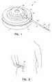
- FIG. 1is a generally perspective view of one form of implantable medicament delivery device of the invention.
- FIG. 2is a generally perspective, illustrative view showing the delivery device of FIG. 1 implanted within the patient's body and illustrating the filling of the reservoir of the device using a conventional, external hypodermic syringe
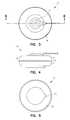
- FIG. 3is a top plan view of the fluid delivery apparatus of the invention shown in FIG. 1 .
- FIG. 4is a side view of the device shown in FIG. 3 .
- FIG. 5is a bottom view of the device shown in FIG. 4 .
- FIG. 6is an enlarged cross-sectional view taken along lines 6 — 6 of FIG. 3 showing the reservoir empty.
- FIG. 7is a cross-sectional view similar to FIG. 6, but showing the reservoir in a filled condition.
- FIG. 8is a cross-sectional view similar to FIG. 7, but showing the expandable gel in an expanded configuration following delivery of substantially all of the medicament to the patient.
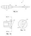
- FIG. 9is a top plan view of the cannula assembly of the apparatus shown in FIG. 1 .
- FIG. 10is a cross-sectional view of the cannula closure member that secures the cannula assembly in position relative to the outlet port of the apparatus.
- FIG. 11is a view taken along lines 11 — 11 of FIG. 10 .
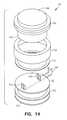
- FIG. 12is a cross-sectional view of the bellows assembly that houses the expandable gel of the apparatus.
- FIG. 13is an enlarged, fragmentary, cross-sectional view of the area designated as 13 in FIG. 12 .
- FIG. 14is a generally perspective, exploded view of the assembly shown in FIG. 12 .
- FIG. 15is an exploded, cross-sectional view of the lower half shell of the apparatus that houses the carrier assembly, the connector ring, the bellows assembly, the expandable gel, the electric circuit and the electronics associated therewith.
- FIG. 16is an exploded, cross-sectional view of the upper half shell of the apparatus that houses the upper reservoir bellows, the ullage and the fill septum assembly.
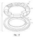
- FIG. 17is a generally perspective, exploded view of the carrier assembly, the printed circuit board and the associated electronics of the apparatus.
- FIG. 18is a generally diagrammatic view showing the relationship among the various components of the central control unit and stimulation means of the embodiment shown in FIG. 1 .
- FIG. 19is a generally perspective view of yet another form of the fluid delivery apparatus of the invention that is implantable within the patient's body.
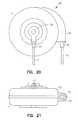
- FIG. 20is a top plan view of the apparatus shown in FIG. 19 .
- FIG. 21is a side-elevational view of the apparatus shown in FIG. 20 .
- FIG. 22is a side-elevational view of the apparatus partly broken away to show internal construction.
- FIG. 23is a top plan view of the apparatus partly broken away to show internal construction.
- FIG. 24is a generally diagrammatic view showing the relationship among the various components of the central control unit and stimulation means of the embodiment shown in FIG. 19 .
- FIG. 25is a generally diagrammatic view further illustrating the relationship among the major operating components of the apparatus including an implantable physiological sensor, system telemetry and external programming capability.
- FIGS. 1 through 18one form of the apparatus of the invention is there shown and generally designated by the numeral 20 .
- this embodiment of the inventionis specially designed to be implanted into the body of the patient.
- the apparatushere comprises a titanium base or shell 22 and a titanium cover or shell 24 that can be joined together as by welding at interface 26 to form the hollow, hermetically sealed housing 28 of the device.
- the deviceis adapted to be implanted within the patient's body at a location immediately below a layer of skin and includes fill means for filling the device reservoir.
- the fill meanshere comprises an access port 30 formed in cover 24 that can be accessed by a hypodermic needle “N”.
- the hypodermic needlecan be inserted through the skin to introduce, via the access port, a quantity of liquid medicament such as heparin, morphine, insulin or like medicament through a septum 34 , which also forms a part of the fill means, into a medicament reservoir 36 .
- a tapered needle guide 38 disposed within the ullage means of the devicesupports septum 34 and guides the entry of the hypodermic needle toward reservoir 36 (FIGS. 6 and 7 ).
- the medicamentis delivered from the delivery device via a cannula port 40 to which a delivery means for delivering fluid to the patient is attached.
- the delivery meanshere comprises a cannula assembly 42 (FIGS. 1 and 8 ).
- Cannula assembly 42is strategically positioned at the time of implant to deliver the medicament to a selected therapeutic site within the patient's body by means of a suitable porous tip cannula, the character of which will presently be described.
- Housing 28houses the novel electrically activated stored energy source of the invention which functions to cause the fluids contained within the sealed reservoir 36 (FIG. 7) of the device, the character of which will presently be described, to flow outwardly thereof through cannula assembly 42 .
- the stored energy sourceis provided in the form of an electroresponsive expandable polymer mass 46 which is disposed within an expandable, hermetically sealed structure or metal bellows assembly 48 that is mounted within housing 28 in the manner best seen in FIGS. 6 , 7 , and 8 .
- expandable mass 46comprises a laminate construction made up of various gel compositions that can be operably associated with one another to perform mechanical work.
- expandable mass 46can comprise a single gel such as, for example, a polyacrylamide gel having certain novel attributes which will presently be described.
- bellows assembly 48includes a base portion 48 a, an upstanding, reduced diameter cover 48 b and an expandable bellows-like sidewall 48 c which are interconnected to define the gel receiving chamber 50 .
- Bellows assembly 48is closely received within a receiving chamber 52 formed in a carrier assembly 54 , which is, in turn, received within base 22 .
- surrounding chamber 52is an electronics receiving channel 56 that supports an annular shaped, printed circuit (PC) board 58 and the electronic components 107 associated therewith, the character of which will presently be described.
- Upstanding cover 48 b of bellows assembly 48is closely received within the lower portion 60 a of a generally annular shaped capture ring 60 (FIGS. 6 and 15) that is disposed intermediate base 22 and cover 24 of housing 28 .
- the base portion 64 a of an expandable bellows structurewhich forms the upper reservoir assembly 64 of the apparatus is receivable within the upper portion 60 b of the capture ring 60 .
- Reservoir assembly 64is operably associated with bellows assembly 48 in the manner shown in FIGS. 7 and 8.
- base portion 64 ais a bellows-like wall 64 b, which cooperates with base portion 64 a to form the expandable fluid reservoir 36 of the apparatus (FIG. 7 ).
- wall 64 bConnected to wall 64 b is a connector flange 64 c that can be sealably interconnected with the lower surface of cover 24 , as by welding, to form a hermetically sealed chamber 68 , a portion of which comprises medicament reservoir 36 (see FIGS. 7 and 16 ).
- a novel co-molded plastic ullage assembly 70Disposed within chamber 68 is a novel co-molded plastic ullage assembly 70 which includes a fluid passageway 72 that is in communication with reservoir 36 via an impedance frit 74 and with cannula port 40 .
- a septum receiving chamber 76Formed within ullage assembly 70 proximate needle guide 38 is a septum receiving chamber 76 that houses septum 34 that is pierceable by the needle “N” of the hypodermic syringe used to fill reservoir 36 .
- Ullage 70is partially encapsulated within an elastomer 77 .
- Septum 34is accessible through a sealing ring 80 that is disposed proximate cover 24 (FIG. 16 ).
- cannula assembly 42comprises an elastomeric molded connector portion 42 a that is provided with a plurality of spaced apart, riblike protuberances 43 .
- a hollow cannula 42 bConnected to connector portion 42 a is a hollow cannula 42 b that includes a porous tip 42 c that permits fluid to flow outwardly through small outlet passageways 83 formed in the porous tip 42 c.
- Connector portion 42 ais sealably receivable within the internally ribbed connector port 84 (FIG. 16 ).
- a threaded cannula closure member 86(FIGS. 10, 11 and 16 ), which is threadably receivable within the threaded connector port 82 formed in ullage 70 functions to hold the cannula assembly in position and to compress connector portion 42 a in a manner to insure maintenance of a leak-tight seal between the cannula assembly and the device housing.
- An appropriate spanner wrench(not shown) can be used to engage apertures 86 a (FIG. 11) to threadably interconnect member 86 with ullage 70 .
- this novel meanshere comprises a source of electric current that includes a generally circular shaped base 90 and first and second upstanding electrodes 92 a and 92 b that are connected to base 90 in the manner best seen in FIG. 14 .
- Electrodes 92 a and 92 bcan be constructed from various materials including platinum and one electrode is positively charged while the other is negatively charged so as to create an electrical field therebetween and across gel 46 .
- Electrodes 92 a and 92 bare interconnected with a source of electrical power such as battery 116 via the circuit interface of a control system by a pair of wire leads 94 (FIGS.
- base 90is supported by a closure plate 102 that is connected to base 48 a of bellows 48 , as by welding, so as to hermetically sealably encapsulate the electrodes in the manner shown in FIG. 12 .
- a spacer ring 103Positioned between base 90 and portion 48 c of the bellows assembly is a spacer ring 103 .
- Another spacer ring 105is positioned between base 90 and plate 102 to permit the passage of wire leads 94 into the housing.
- a bellows clamp ring 104circumscribes the lower portion of the bellows assembly in the manner indicated in FIGS. 12 and 13.
- powercan be supplied to electrodes 92 a and 92 b either continuously or intermittently.
- an electrical fieldwill generated between the electrodes.
- certain types of electroresponsive gelswill swell.
- the act of supplying power to the electrodeswill create an electrical field that will act upon the electroresponsive gel so as to cause an appropriate swelling thereof. This phenomenon will be discussed further hereinafter.
- the characteristics of the expandable gelscan be used to drive the cooperating bellows to cause a controlled expelling of the fluid from reservoir 36 .
- the novel expandable mass or gel 46like most gels, gel or mass 46 is of a semisolid form that can advantageously be handled without external containment under ambient manufacturing conditions.
- gelsare often characterized as soft solids which reside in a state between a liquid and a solid state. Frequently gels comprise a cross-linked network of long polymer molecules with liquid molecules trapped within the network.
- Many gels known in the prior artnot only are capable of significantly large volume change in response to stimulus (phase-transition gels), but also exhibit physical characteristics that enable them to closely conform to the shape of an adjacent member such as a distendable member.
- Phase transition gels best suited for use in constructing the electroresponsive expandable mass of the present inventionare gels which undergo a change in polymer conformation and in so doing exhibit a large volume change at a given phase-transition condition.
- the phase-transition gels in this inventionare multicomponent polymers which can be made to respond with various volume changes to a singular external stimuli to perform useful work.
- the difference in volume between the expanded phase of these phase-transition gels and the contracted phase thereofcan be orders of magnitude.
- Examples of a number of different types of phase-transition gelsare disclosed in Tanaka et al., U.S. Pat. No. 4,732,930; No. Re-35068 and U.S. Pat. No. 5,403,893. Because of the pertinence of these patents, U.S. Pat. Nos. 4,732,930, 5,403,893 and Pat. No. Re-35068 are all hereby incorporated by reference as though fully set forth herein.
- the responsive gelsmay also be reversibly responsive.
- the entire gel, or a component thereofwill undergo a reversible volumetric change which typically involves a shift between two equilibrium states as, for example, expanded and collapsed.
- This reversible volume change of the entire gel, or a component of the gelmay be either continuous or discontinuous.
- a continuous volume changeis marked by a reversible change in volume that occurs over a substantial change in environmental condition.
- the gel, or a component thereofmay undergo a discontinuous volume change in which the reversible transition from expanded to collapsed states, and back again, typically occurs over a relatively small change in environmental condition.
- a gel undergoing a continuous phase-transitionmay have a similar order of magnitude total volume change as a gel undergoing a discontinuous phase-transition.
- volumetric changes in the phase transition gelsresult from competition between intermolecular forces, usually electrostatic in nature. Such volumetric changes are believed to be driven primarily by four fundamental forces, that is ionic, hydrophobic, hydrogen bonding and van der Waals bonding interactions, either alone or in combination.
- Gels suitable for use as the stored energy sources of the present inventioninclude the many polymer gel systems that respond to electrical stimuli.
- it is has long been recognized that such gels swell, shrink and bend in the presence of an electric field(Shiga, T. Proc. Japan Acad. Ser. B 1998, 74,6; Osada Y. J. Macromol. Sci. Chem. 1991, 11-12, 1189; Shinohara, S. J. Intel. Mater. Syst. Struc. 1996, 7, 254; Tanaka, T. Science 1982, 218, 469; Sansinena, J M. Chem. Commun. 1997, 2217; Osada, Y. J. Biomater. Sci. Polymer Edn, 1994, 5,485).
- the response of an electroresponsive gel to an electrical currentdepends largely on the chemical constituents that make up the gel, the chemical species used to carry the applied current and the associated hardware (e.g. the electrodes).
- Tanaka et al.T. Science 1982, 218, 469.
- polyacrylamide gelsthat contained 20% acrylic acid groups were employed. In water, these gels were partially ionized and hence capable of responding to an electrostatic force from an electrode. When the gel was placed between two platinium electrodes and a current was applied, the gel was pulled toward the positive electrode. At applied voltages>1.25 V, the gel collapses greater than 200-fold in volume due to a uniaxial stress along the gel axis. When the applied electric field was removed, the gel returned to its original swollen state.
- analogous collapsible gelscould be made by modifying most polymeric gels such that they contain ionizable carboxylate groups.
- any polyacrylamide gelcould be partially hydrolyzed (in the presence of acid or base) to yield a species that is ionized in water.
- most synthetic polymers that are capable of forming gelscould have carboxylate groups incorporated into the polymeric backbone. This could be accomplished in the initial synthesis of the polymer chains or via cross-linking reactions.
- other anionic functional groups introduced into the gel networkshould cause a swollen gel structure to collapse in the presence of an electric field.
- a polymer gel containing sulfonate (rather than carboxylate) groupsshould respond to an electric field in an analogous way as Tanaka's system previously described.
- Polysulfonate gelshave been described previously by Shirahama et al. (Colloids Surf., A 1996, 112, 233).
- a typical poly(acrylamidosulfonic acid) gelprepared by standard cross linking of, for example 2-acrylamido-2-methylpropanesulfonic acid and N,N′-methylenebis-acrylamide, could also be deprotonated using an alkali solution to yield a polysulfonate gel containing a definite charge.
- Another suitable gel for this deviceis hyaluronic acid hydrogel.
- This materialis a naturally occurring polysaccharide containing ionizable carboxylate groups. In the presence of an electric field of 5 V/cm, this gel loses two-thirds of its volume in 30 min. (Florence, A. T. J Controlled Release 1995, 33, 405). Other researchers have also observed the collapse of polyacrylic acid gel beads in the presence of an electric field (Osada, J. Macromol. Sci. Chem. 1991, 11 & 12, 1189). In these materials, the collapse of the gel was attributed to an electrokinetic phenomenon. That is, the water and ions in the gel migrate toward the electrode bearing the opposite charge to that of the gel. Further it is important to note, that an applied electric field does not induce contraction of neutral hydrogels, i.e. those that do not contain ionized functional groups (Osada, J. Macromol. Sci. Chem. 1991, 11 & 12, 1189). Polyacrylonitrile gel fibers have also been reported as electrically responsive materials.
- a gel that collapses in response to an applied electric fieldcan be reliably used in the devices of the present invention. It should also be noted that by using other gels, or laminate gel constructions, the applied electric field can be started at some relatively high voltage and then decrease at a controlled rate. Under these conditions, the gel will slowly expand and the drug fluid will accordingly be expelled in a correspondingly controlled fashion.
- the electronic controllercan be programmed.
- the electronic controllerhere includes a mircoprocessor, a RAM/ROM memory, a power supply, feed back electronics, amplifiers circuits, timing and control switch matrix circuits and various related circuitry (see FIG. 18 ).
- the controllercan be programmed to enable the precise delivery of varying dosing volumes over time in response to a programmed delivery protocol.
- the electronic controllercan also be programmed to indicate function status to the user.
- the wiring leading to the electronics 107is introduced through the electronic lead cavity 110 formed in base 22 (FIGS. 5 and 17 ).
- the electronic controllercomprises a central processing unit 112 having a memory 114 and a conventional power source such as a commercially available magnesium oxide or lithium battery 116 (FIG. 25 ). Also forming a part of the electronic controller is an electric control unit 118 , a crystal clock 120 and appropriate telemetry 122 .
- FIG. 25shows the relative relationship among the fill means of the device, the fluid reservoir, the device gel reservoir, the electrical source, the catheter and a reservoir positioning sensor, the details of which will presently be described.
- FIG. 25illustrates, in block diagram form, the relationship among these components and the various components that make up the electronics of the device including the central processing unit, the RAM/ROM memory, the digital signal processor, the logic circuit and the telemetry assembly.
- the various electronic components and related systems of the deviceare well known to those skilled in the art and their interconnection and programming to meet the various requirements of the physician and patient protocol are well within the capability of the skilled artesan.
- the devicecan be implanted into the patient.
- the electronicsas well as the method of programming the electronics will be further described.
- expandable gel 46when current flow to electrodes 92 a and 92 b is stopped by the controller, expandable gel 46 will expand to the configuration shown in FIG. 8 .
- fluidcan be introduced into reservoir 36 in the manner previously described via septum 34 so that the apparatus will assume the configuration shown in FIG. 7 .
- the expandable gelUpon interruption of power to electrodes 92 a and 92 b, the expandable gel will expand into the configuration shown in FIG. 8 causing fluid to be expelled from the device via cannula assembly 42 .
- electroresponsive gelscan be used which will expand or swell into the configuration shown in FIG. 8 upon power being supplied to the electrodes.
- FIGS. 19 through 23another form of the apparatus of the invention is there shown and generally designated by the numeral 130 .
- This embodiment of the inventionis similar in many respects to the embodiment shown in FIGS. 1 through 18 and like numerals are used in FIGS. 19 through 23 to identify like components.
- This latest embodimentis also designed to be implanted into the body of the patient in the manner previously described.
- the apparatuscomprises a titanium base or shell 132 and a titanium cover or shell 134 that can be joined together as by welding to form the hollow housing 136 of the device.
- the deviceuniquely includes integral, interactive physiological sensor means and sensor connecting means for interconnecting the sensor with the device electronics disposed within housing 136 .
- the delivery deviceis adapted to be implanted within the patient's body at a location immediately below a layer of skin so that an access port 138 formed in the housing can be accessed by a hypodermic needle to introduce, in the manner previously described, a quantity of liquid medicament such as heparin, morphine, insulin or like medicament through a septum 34 into a drug reservoir.
- a quantity of liquid medicamentsuch as heparin, morphine, insulin or like medicament
- the medicamentis delivered from the delivery device via a cannula port 40 to which a cannula assembly 42 is attached.
- Housing 136houses the novel electrically activated stored energy source of the invention which functions to cause the fluids contained within the sealed reservoir of the device, the character of which was previously described, to flow outwardly thereof through an outlet port formed in cover 134 .
- the electrically activated means or stored energy sourceis provided in the form of an electroresponsive gel which is disposed within an expandable, hermetically sealed metal bellows assembly that is of the character previously described.
- the expandable or swellable massis also of the same character as previously described herein.
- a carrier assembly 54 having an electronics receiving channel 56supports an annular shaped PC board 58 (FIG. 23) and the electronic components associated therewith, the character of which are shown in FIG. 17 and which have previously been described.
- the sensor meanswhich may comprise commercially available chemical, electrochemical, and optical type sensors, here includes a connector 140 , a conduit 142 and a sensor 144 .
- Connector 140includes a ribbed body portion 140 a that is sealably receivable within a threaded receiving opening 146 formed in a protuberance that extends from the periphery of housing 136 in the manner shown in FIGS. 22 and 23 .
- Conduit 142extends through connector 140 and includes connector leads 140 b that are connected to PC board 58 in the manner best seen in FIG. 23.
- a threaded connector 152which is threadably received within threaded receiving opening 154 formed in protuberance 148 , maintains sensor connector 140 securely in position.
- the sensor tip 144is appropriately positioned within the patient at the time of implantation of the delivery device.
- this latest embodiment of the inventionuniquely comprises an In vivo, physiological sensing portion generally designated as 147 that is capable of detecting and responding to the physiological, physiochemical, chemical, optical and electronic changes in the body or bloodstream.
- the physiological sensing portion and its sensing structuremay comprise an electronic, chemical or optical interface designed to measure specific parameters or changes in parameters and to compare known values combined within the associated delivery system electronic memory. It will be clear to those skilled in the art that, when the physiological sensing portion 147 is coupled directly or indirectly with a sensing amplifier 149 (FIG.
- the CPU/electronic controller 157can be programmed to execute a command function signal to initiate control and/or terminate the timed operation and frequency of current flow.
- the resulting processis responsive to the physiological/chemical sensor circuitry and the output can be converted to digital signals and referenced against other controlling data will provide the interactive operating mode of operation of the delivery system.
- telemetry assemblyrelies on the use of a radio frequency transmission system that can readily be adapted from commercially available systems that are well known to those skilled in the art. With the use of such a system, it is possible to up link the system performance, event history data residing in the receiving register and other operating parameters and current values such as the remaining drug volume and battery life.
- the telemetry assemblycan receive down link instructions upon proper interrogation and address confirmation in the programmable system operating mode.
- Such programming changes of function and operating valuescan be implemented and recorded within the delivery system electronics controller memory.
- This programcan also be accomplished through the use of an operably associated portable system programmer and programming head which also can be readily adapted from commercially available systems that are well known to those skilled in the art.
Landscapes
- Health & Medical Sciences (AREA)
- Engineering & Computer Science (AREA)
- Public Health (AREA)
- Life Sciences & Earth Sciences (AREA)
- Veterinary Medicine (AREA)
- Anesthesiology (AREA)
- Biomedical Technology (AREA)
- Heart & Thoracic Surgery (AREA)
- Hematology (AREA)
- General Health & Medical Sciences (AREA)
- Animal Behavior & Ethology (AREA)
- Vascular Medicine (AREA)
- Bioinformatics & Cheminformatics (AREA)
- Chemical & Material Sciences (AREA)
- Medicinal Chemistry (AREA)
- Dermatology (AREA)
- Infusion, Injection, And Reservoir Apparatuses (AREA)
Abstract
Description
Claims (28)
Priority Applications (1)
| Application Number | Priority Date | Filing Date | Title |
|---|---|---|---|
| US09/645,818US6537250B1 (en) | 1997-08-27 | 2000-08-24 | Fluid delivery device with electrically activated energy source |
Applications Claiming Priority (3)
| Application Number | Priority Date | Filing Date | Title |
|---|---|---|---|
| US08/919,147US5961492A (en) | 1997-08-27 | 1997-08-27 | Fluid delivery device with temperature controlled energy source |
| US09/387,447US6174300B1 (en) | 1997-08-27 | 1999-09-01 | Fluid delivery device with temperature controlled energy source |
| US09/645,818US6537250B1 (en) | 1997-08-27 | 2000-08-24 | Fluid delivery device with electrically activated energy source |
Related Parent Applications (1)
| Application Number | Title | Priority Date | Filing Date |
|---|---|---|---|
| US09/387,447DivisionUS6174300B1 (en) | 1997-08-27 | 1999-09-01 | Fluid delivery device with temperature controlled energy source |
Publications (1)
| Publication Number | Publication Date |
|---|---|
| US6537250B1true US6537250B1 (en) | 2003-03-25 |
Family
ID=25441588
Family Applications (3)
| Application Number | Title | Priority Date | Filing Date |
|---|---|---|---|
| US08/919,147Expired - Fee RelatedUS5961492A (en) | 1997-08-27 | 1997-08-27 | Fluid delivery device with temperature controlled energy source |
| US09/387,447Expired - Fee RelatedUS6174300B1 (en) | 1997-08-27 | 1999-09-01 | Fluid delivery device with temperature controlled energy source |
| US09/645,818Expired - Fee RelatedUS6537250B1 (en) | 1997-08-27 | 2000-08-24 | Fluid delivery device with electrically activated energy source |
Family Applications Before (2)
| Application Number | Title | Priority Date | Filing Date |
|---|---|---|---|
| US08/919,147Expired - Fee RelatedUS5961492A (en) | 1997-08-27 | 1997-08-27 | Fluid delivery device with temperature controlled energy source |
| US09/387,447Expired - Fee RelatedUS6174300B1 (en) | 1997-08-27 | 1999-09-01 | Fluid delivery device with temperature controlled energy source |
Country Status (7)
| Country | Link |
|---|---|
| US (3) | US5961492A (en) |
| EP (1) | EP1023103A4 (en) |
| JP (1) | JP2001513409A (en) |
| AU (1) | AU8922898A (en) |
| BR (1) | BR9815587A (en) |
| CA (1) | CA2302696A1 (en) |
| WO (1) | WO1999010040A1 (en) |
Cited By (28)
| Publication number | Priority date | Publication date | Assignee | Title |
|---|---|---|---|---|
| US20040121486A1 (en)* | 2002-08-16 | 2004-06-24 | Uhland Scott A. | Controlled release device and method using electrothermal ablation |
| US20040143236A1 (en)* | 1999-08-18 | 2004-07-22 | Santini John T. | Thermally-activated reservoir devices |
| US20050077584A1 (en)* | 2001-06-28 | 2005-04-14 | Uhland Scott A. | Hermetically sealed microchip reservoir devices |
| US20050096587A1 (en)* | 2003-11-03 | 2005-05-05 | Santini John T.Jr. | Medical device for sensing glucose |
| US20050124979A1 (en)* | 2000-03-02 | 2005-06-09 | Santini John T.Jr. | Device for release of chemical molecules using pressure-generated rupture of reservoirs |
| US20050143715A1 (en)* | 2001-05-31 | 2005-06-30 | Cima Michael J. | Device for controlled reservoir opening with reinforced reservoir caps |
| US20050149000A1 (en)* | 1996-07-02 | 2005-07-07 | Santini John T.Jr. | Medical device with controlled reservoir opening |
| US20050267440A1 (en)* | 2004-06-01 | 2005-12-01 | Herman Stephen J | Devices and methods for measuring and enhancing drug or analyte transport to/from medical implant |
| US20060024358A1 (en)* | 2004-07-30 | 2006-02-02 | Santini John T Jr | Multi-reservoir device for transdermal drug delivery and sensing |
| US20060057737A1 (en)* | 2004-09-01 | 2006-03-16 | Santini John T Jr | Multi-cap reservoir devices for controlled release or exposure of reservoir contents |
| US20060171989A1 (en)* | 2005-01-25 | 2006-08-03 | Prescott James H | Control of drug release by transient modification of local microenvironments |
| US20060217798A1 (en)* | 1999-11-17 | 2006-09-28 | Boston Scientific Scimed, Inc. | Stent having active release reservoirs |
| WO2007010522A1 (en)* | 2005-07-21 | 2007-01-25 | Steadymed. Ltd., | Drug delivery device with electrically controlled volume changing means |
| US20080221557A1 (en)* | 2001-01-09 | 2008-09-11 | Microchips, Inc. | Method of opening reservoir of containment device |
| US7534241B2 (en) | 2002-09-23 | 2009-05-19 | Microchips, Inc. | Micro-reservoir osmotic release systems and microtube array device |
| US8126736B2 (en) | 2009-01-23 | 2012-02-28 | Warsaw Orthopedic, Inc. | Methods and systems for diagnosing, treating, or tracking spinal disorders |
| US8685093B2 (en) | 2009-01-23 | 2014-04-01 | Warsaw Orthopedic, Inc. | Methods and systems for diagnosing, treating, or tracking spinal disorders |
| US8834454B2 (en) | 2006-05-07 | 2014-09-16 | Steadymed Ltd. | Drug delivery device |
| US9687186B2 (en) | 2005-07-21 | 2017-06-27 | Steadymed Ltd. | Drug delivery device |
| US9724462B2 (en) | 2012-03-19 | 2017-08-08 | Steadymed Ltd. | Fluid-connection mechanism for patch-pumps |
| US10071209B2 (en) | 2012-03-15 | 2018-09-11 | Steadymed Ltd. | Enhanced infusion-site pain-reduction for drug-delivery devices |
| US10112005B2 (en) | 2010-09-27 | 2018-10-30 | Steadymed, Ltd. | Size-efficient drug-delivery device |
| US10300505B2 (en) | 2011-08-26 | 2019-05-28 | Nordson Corporation | Modular jetting devices |
| US10463847B2 (en) | 2015-06-11 | 2019-11-05 | Steadymed Ltd. | Infusion set |
| US20210393873A1 (en)* | 2020-06-23 | 2021-12-23 | Tecmed Ag | Wearable drug delivery device |
| US11364339B2 (en) | 2019-07-11 | 2022-06-21 | Aamir Zain Jamal | Infusion unit |
| US11980737B2 (en) | 2020-06-23 | 2024-05-14 | Tecmed Ag | Wearable drug delivery device |
| US12440618B2 (en) | 2020-06-23 | 2025-10-14 | Tecmed Ag | Wearable drug delivery device |
Families Citing this family (129)
| Publication number | Priority date | Publication date | Assignee | Title |
|---|---|---|---|---|
| US6629963B2 (en)* | 1996-06-20 | 2003-10-07 | Becton, Dickinson And Company | Syringe and needle shield assembly and method of sterilizing such assembly |
| WO1998038953A1 (en) | 1997-03-03 | 1998-09-11 | Medical Solutions, Inc. | Method and apparatus for pressure infusion and temperature control of infused liquids |
| US7090658B2 (en) | 1997-03-03 | 2006-08-15 | Medical Solutions, Inc. | Temperature sensing device for selectively measuring temperature at desired locations along an intravenous fluid line |
| JP3207799B2 (en)* | 1997-12-03 | 2001-09-10 | 株式会社パイオラックス | Continuous chemical injector |
| US7041941B2 (en) | 1997-04-07 | 2006-05-09 | Patented Medical Solutions, Llc | Medical item thermal treatment systems and method of monitoring medical items for compliance with prescribed requirements |
| US6768085B2 (en) | 2001-07-02 | 2004-07-27 | Medical Solutions, Inc. | Medical solution warming system and method of heating and maintaining medical solutions at desired temperatures |
| US7276675B2 (en) | 1997-04-07 | 2007-10-02 | Patented Medical Solutions, Llc | Medical item thermal treatment systems and method of monitoring medical items for compliance with prescribed requirements |
| US6467953B1 (en) | 1999-03-30 | 2002-10-22 | Medical Solutions, Inc. | Method and apparatus for monitoring temperature of intravenously delivered fluids and other medical items |
| WO1998045658A1 (en) | 1997-04-07 | 1998-10-15 | Medical Solutions, Inc. | Warming system and method for heating various items utilized in surgical procedures |
| US6660974B2 (en) | 1997-04-07 | 2003-12-09 | Medical Solutions, Inc. | Warming system and method for heating various items utilized in surgical procedures |
| US6045759A (en)* | 1997-08-11 | 2000-04-04 | Ventana Medical Systems | Fluid dispenser |
| US20020110494A1 (en)* | 2000-01-14 | 2002-08-15 | Ventana Medical Systems, Inc. | Method and apparatus for modifying pressure within a fluid dispenser |
| US20050135972A1 (en)* | 1997-08-11 | 2005-06-23 | Ventana Medical Systems, Inc. | Method and apparatus for modifying pressure within a fluid dispenser |
| US6093574A (en) | 1997-08-11 | 2000-07-25 | Ventana Medical Systems | Method and apparatus for rinsing a microscope slide |
| US8137619B2 (en)* | 1997-08-11 | 2012-03-20 | Ventana Medical Systems, Inc. | Memory management method and apparatus for automated biological reaction system |
| US6527744B1 (en)* | 1997-08-27 | 2003-03-04 | Science Incorporated | Fluid delivery device with light activated energy source |
| US5961492A (en) | 1997-08-27 | 1999-10-05 | Science Incorporated | Fluid delivery device with temperature controlled energy source |
| US6126637A (en)* | 1998-04-15 | 2000-10-03 | Science Incorporated | Fluid delivery device with collapsible needle cover |
| US6669669B2 (en)* | 2001-10-12 | 2003-12-30 | Insulet Corporation | Laminated patient infusion device |
| CA2421133C (en) | 2000-09-08 | 2012-06-26 | Insulet Corporation | Devices, systems and methods for patient infusion |
| US6537249B2 (en)* | 2000-12-18 | 2003-03-25 | Science, Incorporated | Multiple canopy |
| AU2002239709B2 (en) | 2000-12-21 | 2007-02-15 | Insulet Corporation | Medical apparatus remote control and method |
| EP1381408A4 (en) | 2001-02-22 | 2007-06-13 | Insulet Corp | Modular infusion device and method |
| US7238171B2 (en) | 2001-03-12 | 2007-07-03 | Medical Solutions, Inc. | Method and apparatus for controlling pressurized infusion and temperature of infused liquids |
| US7031602B2 (en) | 2001-03-12 | 2006-04-18 | Patented Medical Solutions, Llc | Method and apparatus for controlling temperature of infused liquids |
| US8226605B2 (en) | 2001-12-17 | 2012-07-24 | Medical Solutions, Inc. | Method and apparatus for heating solutions within intravenous lines to desired temperatures during infusion |
| US6692457B2 (en) | 2002-03-01 | 2004-02-17 | Insulet Corporation | Flow condition sensor assembly for patient infusion device |
| US6830558B2 (en) | 2002-03-01 | 2004-12-14 | Insulet Corporation | Flow condition sensor assembly for patient infusion device |
| EP3351277A1 (en) | 2002-03-26 | 2018-07-25 | Becton, Dickinson and Company | Multi-stage fluid delivery device and method |
| US7115108B2 (en)* | 2002-04-02 | 2006-10-03 | Becton, Dickinson And Company | Method and device for intradermally delivering a substance |
| US6960192B1 (en) | 2002-04-23 | 2005-11-01 | Insulet Corporation | Transcutaneous fluid delivery system |
| US20040153032A1 (en)* | 2002-04-23 | 2004-08-05 | Garribotto John T. | Dispenser for patient infusion device |
| US20050238507A1 (en)* | 2002-04-23 | 2005-10-27 | Insulet Corporation | Fluid delivery device |
| US7018360B2 (en) | 2002-07-16 | 2006-03-28 | Insulet Corporation | Flow restriction system and method for patient infusion device |
| CN100479875C (en)* | 2002-07-22 | 2009-04-22 | 贝克顿·迪金森公司 | Patch-like infusion device |
| US7128727B2 (en) | 2002-09-30 | 2006-10-31 | Flaherty J Christopher | Components and methods for patient infusion device |
| US7144384B2 (en) | 2002-09-30 | 2006-12-05 | Insulet Corporation | Dispenser components and methods for patient infusion device |
| US20040116866A1 (en)* | 2002-12-17 | 2004-06-17 | William Gorman | Skin attachment apparatus and method for patient infusion device |
| US20050182366A1 (en)* | 2003-04-18 | 2005-08-18 | Insulet Corporation | Method For Visual Output Verification |
| US20040220551A1 (en)* | 2003-04-30 | 2004-11-04 | Flaherty J. Christopher | Low profile components for patient infusion device |
| EP3695862A1 (en) | 2003-08-12 | 2020-08-19 | Becton, Dickinson and Company | Patch-like infusion device |
| US20050065760A1 (en)* | 2003-09-23 | 2005-03-24 | Robert Murtfeldt | Method for advising patients concerning doses of insulin |
| US20050070847A1 (en)* | 2003-09-29 | 2005-03-31 | Van Erp Wilhelmus Petrus Martinus Maria | Rapid-exchange balloon catheter with hypotube shaft |
| KR20060099520A (en) | 2003-10-21 | 2006-09-19 | 노보 노르디스크 에이/에스 | Medical Skin Mounting Device |
| EP1527792A1 (en)* | 2003-10-27 | 2005-05-04 | Novo Nordisk A/S | Medical injection device mountable to the skin |
| PL1682203T3 (en) | 2003-10-23 | 2010-06-30 | Novo Nordisk As | Medical injection device mountable to the skin |
| DE602004025025D1 (en)* | 2003-10-27 | 2010-02-25 | Novo Nordisk As | ON THE SKIN FIXABLE MEDICAL INJECTION DEVICE |
| AU2004298287B2 (en)* | 2003-12-16 | 2010-09-16 | Chimden Medical Pty. Ltd. | Fluid delivery device |
| CA2557469C (en)* | 2003-12-16 | 2011-05-10 | Ultimate Medical Pty. Ltd. | Fluid delivery device |
| US7611504B1 (en) | 2004-03-09 | 2009-11-03 | Patented Medical Solutions Llc | Method and apparatus for facilitating injection of medication into an intravenous fluid line while maintaining sterility of infused fluids |
| KR101122334B1 (en)* | 2004-11-05 | 2012-03-28 | 감브로 룬디아 아베 | Catheter for vascular access and method for manufacturing the same |
| US20060178633A1 (en)* | 2005-02-03 | 2006-08-10 | Insulet Corporation | Chassis for fluid delivery device |
| WO2006108809A1 (en) | 2005-04-13 | 2006-10-19 | Novo Nordisk A/S | Medical skin mountable device and system |
| US8105280B2 (en)* | 2005-05-17 | 2012-01-31 | Medingo, Ltd. | Disposable dispenser for patient infusion |
| US7552240B2 (en)* | 2005-05-23 | 2009-06-23 | International Business Machines Corporation | Method for user space operations for direct I/O between an application instance and an I/O adapter |
| US20090118682A1 (en)* | 2005-09-13 | 2009-05-07 | Novo Nordisk A/S | Reservoir Device With Inspection Aid For Detection Of Drug Condition |
| WO2007045644A1 (en)* | 2005-10-17 | 2007-04-26 | Novo Nordisk A/S | Vented drug reservoir unit |
| US7740611B2 (en) | 2005-10-27 | 2010-06-22 | Patented Medical Solutions, Llc | Method and apparatus to indicate prior use of a medical item |
| US20070130981A1 (en)* | 2005-10-31 | 2007-06-14 | Tactical Medical Solutions, Llc | Evaporative cooling apparatus for iv fluids |
| US8487738B2 (en) | 2006-03-20 | 2013-07-16 | Medical Solutions, Inc. | Method and apparatus for securely storing medical items within a thermal treatment system |
| WO2007139799A2 (en)* | 2006-05-24 | 2007-12-06 | Mayo Foundation For Medical Education And Research | Devices and methods for crossing chronic total occlusions |
| EP1884284A1 (en)* | 2006-08-04 | 2008-02-06 | Samsung Electronics Co., Ltd. | Closing valve unit and reaction apparatus having closing valve |
| US8202267B2 (en) | 2006-10-10 | 2012-06-19 | Medsolve Technologies, Inc. | Method and apparatus for infusing liquid to a body |
| US20080161754A1 (en)* | 2006-12-29 | 2008-07-03 | Medsolve Technologies, Inc. | Method and apparatus for infusing liquid to a body |
| US8226293B2 (en) | 2007-02-22 | 2012-07-24 | Medical Solutions, Inc. | Method and apparatus for measurement and control of temperature for infused liquids |
| US7892213B2 (en)* | 2007-04-20 | 2011-02-22 | Carefusion 303, Inc. | Fluid flow control system having capillary fluid flow restrictor |
| US8708961B2 (en) | 2008-01-28 | 2014-04-29 | Medsolve Technologies, Inc. | Apparatus for infusing liquid to a body |
| US7959598B2 (en) | 2008-08-20 | 2011-06-14 | Asante Solutions, Inc. | Infusion pump systems and methods |
| US9375529B2 (en)* | 2009-09-02 | 2016-06-28 | Becton, Dickinson And Company | Extended use medical device |
| US10092691B2 (en) | 2009-09-02 | 2018-10-09 | Becton, Dickinson And Company | Flexible and conformal patch pump |
| DK2512560T3 (en) | 2009-12-16 | 2018-07-16 | Becton Dickinson Co | Even injector device |
| CN102753221B (en) | 2009-12-16 | 2017-04-26 | 贝克顿·迪金森公司 | self-injection device |
| JP5650241B2 (en) | 2009-12-16 | 2015-01-07 | ベクトン・ディキンソン・アンド・カンパニーBecton, Dickinson And Company | Self injection device |
| WO2011075103A1 (en) | 2009-12-16 | 2011-06-23 | Becton, Dickinson And Company | Self-injection device |
| JP5650755B2 (en) | 2009-12-16 | 2015-01-07 | ベクトン・ディキンソン・アンド・カンパニーBecton, Dickinson And Company | Self injection device |
| DK2781228T3 (en) | 2009-12-16 | 2016-03-21 | Becton Dickinson Co | A device for self-injection |
| US8753587B2 (en)* | 2009-12-31 | 2014-06-17 | General Electric Company | Microvalve |
| CN103153360B (en) | 2010-09-02 | 2016-04-06 | 贝克顿·迪金森公司 | Have band activate interceptor pin lid from injection device |
| US20120191074A1 (en)* | 2011-01-21 | 2012-07-26 | Palyon Medical (Bvi) Limited | Reduced sized programmable pump |
| DK2715370T3 (en) | 2011-06-01 | 2018-05-14 | Ventana Med Syst Inc | DISPENSES WITH FILTER EQUIPMENT |
| US9211381B2 (en) | 2012-01-20 | 2015-12-15 | Medical Solutions, Inc. | Method and apparatus for controlling temperature of medical liquids |
| US9844631B2 (en)* | 2012-03-13 | 2017-12-19 | Becton Dickinson France | Injection device having a miniaturized drug delivery portion |
| EP4406568A3 (en) | 2012-03-30 | 2024-10-16 | Insulet Corporation | Fluid delivery device with transcutaneous access tool, insertion mechanism and blood glucose monitoring for use therewith |
| US9789418B2 (en)* | 2012-08-09 | 2017-10-17 | Doskocil Manufacturing Company, Inc. | Amusement toy |
| EP2882473B1 (en)* | 2012-08-13 | 2019-09-25 | TG Medwise Ltd. | Substance delivery device |
| US9656029B2 (en) | 2013-02-15 | 2017-05-23 | Medical Solutions, Inc. | Plural medical item warming system and method for warming a plurality of medical items to desired temperatures |
| US9561324B2 (en) | 2013-07-19 | 2017-02-07 | Bigfoot Biomedical, Inc. | Infusion pump system and method |
| US9399216B2 (en) | 2013-12-30 | 2016-07-26 | General Electric Company | Fluid transport in microfluidic applications with sensors for detecting fluid presence and pressure |
| US10076751B2 (en) | 2013-12-30 | 2018-09-18 | General Electric Company | Systems and methods for reagent storage |
| US10716896B2 (en) | 2015-11-24 | 2020-07-21 | Insulet Corporation | Wearable automated medication delivery system |
| US10413665B2 (en) | 2015-11-25 | 2019-09-17 | Insulet Corporation | Wearable medication delivery device |
| EP3374905A1 (en) | 2016-01-13 | 2018-09-19 | Bigfoot Biomedical, Inc. | User interface for diabetes management system |
| HK1256995A1 (en) | 2016-01-14 | 2019-10-11 | Bigfoot Biomedical, Inc. | Occlusion resolution in medication delivery devices, systems, and methods |
| US10806859B2 (en) | 2016-01-14 | 2020-10-20 | Bigfoot Biomedical, Inc. | Adjusting insulin delivery rates |
| US12383166B2 (en) | 2016-05-23 | 2025-08-12 | Insulet Corporation | Insulin delivery system and methods with risk-based set points |
| US10363374B2 (en) | 2016-05-26 | 2019-07-30 | Insulet Corporation | Multi-dose drug delivery device |
| US10363372B2 (en) | 2016-08-12 | 2019-07-30 | Insulet Corporation | Plunger for drug delivery device |
| EP3730169B1 (en) | 2016-08-14 | 2023-08-02 | Insulet Corporation | Drug delivery device with detection of position of the plunger |
| MX2019001362A (en) | 2016-08-24 | 2019-07-10 | Avent Inc | Flow indicator for an infusion pump. |
| US20180055737A1 (en)* | 2016-08-25 | 2018-03-01 | Stephanie Figueroa | Overdose Protecting Dispensing Device |
| US20200041430A1 (en)* | 2016-10-06 | 2020-02-06 | Wake Forest University Health Sciences | Devices and methods to evaluate tissue cooling |
| WO2018067645A1 (en) | 2016-10-07 | 2018-04-12 | Insulet Corporation | Multi-stage delivery system |
| US10780217B2 (en) | 2016-11-10 | 2020-09-22 | Insulet Corporation | Ratchet drive for on body delivery system |
| EP3500161A4 (en) | 2016-12-12 | 2020-01-08 | Bigfoot Biomedical, Inc. | ALARMS AND WARNINGS FOR MEDICINE DELIVERY DEVICES AND RELATED SYSTEMS AND METHODS |
| US10500334B2 (en) | 2017-01-13 | 2019-12-10 | Bigfoot Biomedical, Inc. | System and method for adjusting insulin delivery |
| US10881792B2 (en) | 2017-01-13 | 2021-01-05 | Bigfoot Biomedical, Inc. | System and method for adjusting insulin delivery |
| US10758675B2 (en) | 2017-01-13 | 2020-09-01 | Bigfoot Biomedical, Inc. | System and method for adjusting insulin delivery |
| EP3568859A1 (en) | 2017-01-13 | 2019-11-20 | Bigfoot Biomedical, Inc. | Insulin delivery methods, systems and devices |
| WO2018136699A1 (en) | 2017-01-19 | 2018-07-26 | Insulet Corporation | Cartridge hold-up volume reduction |
| WO2018156548A1 (en) | 2017-02-22 | 2018-08-30 | Insulet Corporation | Needle insertion mechanisms for drug containers |
| US10695485B2 (en) | 2017-03-07 | 2020-06-30 | Insulet Corporation | Very high volume user filled drug delivery device |
| US10973978B2 (en) | 2017-08-03 | 2021-04-13 | Insulet Corporation | Fluid flow regulation arrangements for drug delivery devices |
| US11280327B2 (en) | 2017-08-03 | 2022-03-22 | Insulet Corporation | Micro piston pump |
| JP2020532477A (en)* | 2017-08-24 | 2020-11-12 | サザランド,スペンサー,ディー. | Distribution device |
| US11786668B2 (en) | 2017-09-25 | 2023-10-17 | Insulet Corporation | Drug delivery devices, systems, and methods with force transfer elements |
| EP3687600B1 (en) | 2017-09-26 | 2022-04-27 | Insulet Corporation | Needle mechanism module for drug delivery device |
| US11147931B2 (en) | 2017-11-17 | 2021-10-19 | Insulet Corporation | Drug delivery device with air and backflow elimination |
| USD928199S1 (en) | 2018-04-02 | 2021-08-17 | Bigfoot Biomedical, Inc. | Medication delivery device with icons |
| US10874803B2 (en) | 2018-05-31 | 2020-12-29 | Insulet Corporation | Drug cartridge with drive system |
| US11229736B2 (en) | 2018-06-06 | 2022-01-25 | Insulet Corporation | Linear shuttle pump for drug delivery |
| CA3060234A1 (en)* | 2018-11-20 | 2020-05-20 | Becton, Dickinson And Company | Fluid path channel and adsorbent |
| US11446435B2 (en) | 2018-11-28 | 2022-09-20 | Insulet Corporation | Drug delivery shuttle pump system and valve assembly |
| USD920343S1 (en) | 2019-01-09 | 2021-05-25 | Bigfoot Biomedical, Inc. | Display screen or portion thereof with graphical user interface associated with insulin delivery |
| WO2020250771A1 (en)* | 2019-06-11 | 2020-12-17 | 富士フイルム株式会社 | Microneedle array unit and container |
| US11369735B2 (en) | 2019-11-05 | 2022-06-28 | Insulet Corporation | Component positioning of a linear shuttle pump |
| WO2022133218A1 (en) | 2020-12-18 | 2022-06-23 | Insulet Corporation | Adhesive pad with a metallic coil for securing an on-body medical device |
| AU2022205300B2 (en) | 2021-01-08 | 2025-04-17 | Insulet Corporation | Single actuated precision dose intermediate pumping chamber |
| EP4346945A1 (en) | 2021-05-28 | 2024-04-10 | Insulet Corporation | Spring-based status sensors |
| US12097355B2 (en) | 2023-01-06 | 2024-09-24 | Insulet Corporation | Automatically or manually initiated meal bolus delivery with subsequent automatic safety constraint relaxation |
Citations (6)
| Publication number | Priority date | Publication date | Assignee | Title |
|---|---|---|---|---|
| US5267980A (en) | 1990-08-29 | 1993-12-07 | Random Corporation | Optical components for an I.V. flow detector |
| US5368570A (en)* | 1991-11-12 | 1994-11-29 | Imed Corporation | Apparatus for infusing medical solutions |
| US5403893A (en) | 1991-01-31 | 1995-04-04 | Massachusetts Institute Of Technology | Interpenetrating-polymer network phase-transition gels |
| US5505706A (en) | 1989-01-10 | 1996-04-09 | Maus; Daryl D. | Heat-activated drug delivery system and thermal actuators therefor |
| US5721382A (en) | 1995-05-01 | 1998-02-24 | Kriesel; Marshall S. | Apparatus for indicating fluid pressure within a conduit |
| US5961492A (en) | 1997-08-27 | 1999-10-05 | Science Incorporated | Fluid delivery device with temperature controlled energy source |
Family Cites Families (8)
| Publication number | Priority date | Publication date | Assignee | Title |
|---|---|---|---|---|
| US35068A (en)* | 1862-04-29 | John f | ||
| USRE35068E (en) | 1983-01-28 | 1995-10-17 | Massachusetts Institute Of Technology | Collapsible gel compositions |
| US4732930A (en)* | 1985-05-20 | 1988-03-22 | Massachusetts Institute Of Technology | Reversible, discontinuous volume changes of ionized isopropylacrylamide cells |
| AU3274895A (en)* | 1994-07-18 | 1996-02-16 | Gel Sciences, Inc. | Novel polymer gel networks and methods of use |
| US5616127A (en)* | 1994-11-14 | 1997-04-01 | Smith; Kevin | Expandable liquid infusion device |
| US5595706A (en)* | 1994-12-29 | 1997-01-21 | Philip Morris Incorporated | Aluminum containing iron-base alloys useful as electrical resistance heating elements |
| US5651979A (en)* | 1995-03-30 | 1997-07-29 | Gel Sciences, Inc. | Apparatus and method for delivering a biologically active compound into a biological environment |
| US5693018A (en)* | 1995-10-11 | 1997-12-02 | Science Incorporated | Subdermal delivery device |
- 1997
- 1997-08-27USUS08/919,147patent/US5961492A/ennot_activeExpired - Fee Related
- 1998
- 1998-08-27CACA002302696Apatent/CA2302696A1/ennot_activeAbandoned
- 1998-08-27AUAU89228/98Apatent/AU8922898A/ennot_activeAbandoned
- 1998-08-27BRBR9815587-3Apatent/BR9815587A/ennot_activeApplication Discontinuation
- 1998-08-27WOPCT/US1998/017766patent/WO1999010040A1/ennot_activeApplication Discontinuation
- 1998-08-27EPEP98941085Apatent/EP1023103A4/ennot_activeWithdrawn
- 1998-08-27JPJP2000507426Apatent/JP2001513409A/ennot_activeWithdrawn
- 1999
- 1999-09-01USUS09/387,447patent/US6174300B1/ennot_activeExpired - Fee Related
- 2000
- 2000-08-24USUS09/645,818patent/US6537250B1/ennot_activeExpired - Fee Related
Patent Citations (6)
| Publication number | Priority date | Publication date | Assignee | Title |
|---|---|---|---|---|
| US5505706A (en) | 1989-01-10 | 1996-04-09 | Maus; Daryl D. | Heat-activated drug delivery system and thermal actuators therefor |
| US5267980A (en) | 1990-08-29 | 1993-12-07 | Random Corporation | Optical components for an I.V. flow detector |
| US5403893A (en) | 1991-01-31 | 1995-04-04 | Massachusetts Institute Of Technology | Interpenetrating-polymer network phase-transition gels |
| US5368570A (en)* | 1991-11-12 | 1994-11-29 | Imed Corporation | Apparatus for infusing medical solutions |
| US5721382A (en) | 1995-05-01 | 1998-02-24 | Kriesel; Marshall S. | Apparatus for indicating fluid pressure within a conduit |
| US5961492A (en) | 1997-08-27 | 1999-10-05 | Science Incorporated | Fluid delivery device with temperature controlled energy source |
Cited By (73)
| Publication number | Priority date | Publication date | Assignee | Title |
|---|---|---|---|---|
| US20080047926A1 (en)* | 1996-07-02 | 2008-02-28 | Massachusetts Institute Of Technology | Method for Making Microchip Reservoir Device |
| US7901397B2 (en) | 1996-07-02 | 2011-03-08 | Massachusetts Institute Of Technology | Method for operating microchip reservoir device |
| US7892221B2 (en) | 1996-07-02 | 2011-02-22 | Massachusetts Institute Of Technology | Method of controlled drug delivery from implant device |
| US20050149000A1 (en)* | 1996-07-02 | 2005-07-07 | Santini John T.Jr. | Medical device with controlled reservoir opening |
| US7473248B2 (en) | 1999-08-18 | 2009-01-06 | Microchips, Inc. | Thermally-activated reservoir devices |
| US20040143236A1 (en)* | 1999-08-18 | 2004-07-22 | Santini John T. | Thermally-activated reservoir devices |
| US20060217798A1 (en)* | 1999-11-17 | 2006-09-28 | Boston Scientific Scimed, Inc. | Stent having active release reservoirs |
| US20050124979A1 (en)* | 2000-03-02 | 2005-06-09 | Santini John T.Jr. | Device for release of chemical molecules using pressure-generated rupture of reservoirs |
| US7648677B2 (en) | 2000-03-02 | 2010-01-19 | Microchips, Inc. | Method for operating a reservoir-based sensor device |
| US7614135B2 (en) | 2000-03-02 | 2009-11-10 | Microchips, Inc. | Method for making reservoir-based sensor device |
| US20100137696A1 (en)* | 2000-03-02 | 2010-06-03 | Microchips, Inc. | Medical device with reservoir-based sensors |
| US7410616B2 (en) | 2000-03-02 | 2008-08-12 | Microchips, Inc. | Device for the controlled exposure of reservoir-based sensors |
| US20080115361A1 (en)* | 2000-03-02 | 2008-05-22 | Microchips, Inc. | Method for Making Reservoir-Based Sensor Device |
| US20080115559A1 (en)* | 2000-03-02 | 2008-05-22 | Microchips, Inc. | Method for Operating a Reservoir-Based Sensor Device |
| US20070299385A1 (en)* | 2000-03-02 | 2007-12-27 | Microchips, Inc. | Device for the controlled exposure of reservoir-based sensors |
| US8442611B2 (en) | 2000-03-02 | 2013-05-14 | Microchips, Inc. | Medical device with reservoir-based sensors |
| US7776024B2 (en) | 2001-01-09 | 2010-08-17 | Microchips, Inc. | Method of actuating implanted medical device |
| US20080221557A1 (en)* | 2001-01-09 | 2008-09-11 | Microchips, Inc. | Method of opening reservoir of containment device |
| US7879019B2 (en) | 2001-01-09 | 2011-02-01 | Microchips, Inc. | Method of opening reservoir of containment device |
| US20050143715A1 (en)* | 2001-05-31 | 2005-06-30 | Cima Michael J. | Device for controlled reservoir opening with reinforced reservoir caps |
| US7497846B2 (en) | 2001-06-28 | 2009-03-03 | Microchips, Inc. | Hermetically sealed microchip reservoir devices |
| US20050077584A1 (en)* | 2001-06-28 | 2005-04-14 | Uhland Scott A. | Hermetically sealed microchip reservoir devices |
| US20090030404A1 (en)* | 2002-08-16 | 2009-01-29 | Microchips, Inc. | Containment device with multi-layer reservoir cap structure |
| US7910151B2 (en) | 2002-08-16 | 2011-03-22 | Microchips, Inc. | Method for making device for controlled reservoir opening by electrothermal ablation |
| US8211092B2 (en) | 2002-08-16 | 2012-07-03 | Microchips, Inc. | Containment device with multi-layer reservoir cap structure |
| US20060100608A1 (en)* | 2002-08-16 | 2006-05-11 | Uhland Scott A | Controlled release device and method using electrothermal ablation |
| US7510551B2 (en) | 2002-08-16 | 2009-03-31 | Microchips, Inc. | Controlled release device and method using electrothermal ablation |
| US7455667B2 (en) | 2002-08-16 | 2008-11-25 | Microchips, Inc. | Controlled release device and method using electrothermal ablation |
| US20040121486A1 (en)* | 2002-08-16 | 2004-06-24 | Uhland Scott A. | Controlled release device and method using electrothermal ablation |
| US20080168921A1 (en)* | 2002-08-16 | 2008-07-17 | Uhland Scott A | Method for making device for controlled reservoir opening by electrothermal ablation |
| US7534241B2 (en) | 2002-09-23 | 2009-05-19 | Microchips, Inc. | Micro-reservoir osmotic release systems and microtube array device |
| US8095197B2 (en) | 2003-11-03 | 2012-01-10 | Microchips, Inc. | Medical device for sensing glucose |
| US20050096587A1 (en)* | 2003-11-03 | 2005-05-05 | Santini John T.Jr. | Medical device for sensing glucose |
| US20050267440A1 (en)* | 2004-06-01 | 2005-12-01 | Herman Stephen J | Devices and methods for measuring and enhancing drug or analyte transport to/from medical implant |
| US20060024358A1 (en)* | 2004-07-30 | 2006-02-02 | Santini John T Jr | Multi-reservoir device for transdermal drug delivery and sensing |
| US20090234214A1 (en)* | 2004-07-30 | 2009-09-17 | Microchips, Inc. | Multi-reservoir device and method for transdermal sensing |
| US7537590B2 (en) | 2004-07-30 | 2009-05-26 | Microchips, Inc. | Multi-reservoir device for transdermal drug delivery and sensing |
| US8403915B2 (en) | 2004-09-01 | 2013-03-26 | Microchips, Inc. | Multi-opening reservoir devices for controlled release or exposure of reservoir contents |
| US20060057737A1 (en)* | 2004-09-01 | 2006-03-16 | Santini John T Jr | Multi-cap reservoir devices for controlled release or exposure of reservoir contents |
| US7604628B2 (en) | 2004-09-01 | 2009-10-20 | Microchips, Inc. | Multi-cap reservoir devices for controlled release or exposure of reservoir contents |
| US20100042075A1 (en)* | 2004-09-01 | 2010-02-18 | Microchips, Inc. | Multi-opening reservoir devices for controlled release or exposure of reservoir contents |
| US7488316B2 (en) | 2005-01-25 | 2009-02-10 | Microchips, Inc. | Control of drug release by transient modification of local microenvironments |
| US20060171989A1 (en)* | 2005-01-25 | 2006-08-03 | Prescott James H | Control of drug release by transient modification of local microenvironments |
| WO2007010522A1 (en)* | 2005-07-21 | 2007-01-25 | Steadymed. Ltd., | Drug delivery device with electrically controlled volume changing means |
| US9687186B2 (en) | 2005-07-21 | 2017-06-27 | Steadymed Ltd. | Drug delivery device |
| US12097028B2 (en) | 2005-07-21 | 2024-09-24 | United Therapeutics Corporation | Drug delivery device with electrically controlled volume changing means |
| EP2626094A1 (en)* | 2005-07-21 | 2013-08-14 | Steadymed. Ltd. | Drug delivery device with electrically controlled volume changing means |
| US10750987B2 (en)* | 2005-07-21 | 2020-08-25 | Steadymed Ltd. | Drug delivery device with electrically controlled volume changing means |
| US20090093772A1 (en)* | 2005-07-21 | 2009-04-09 | Steadymed. Ltd. | Drug Delivery Device with Electrically Controlled Volume Changing Means |
| US20180035935A1 (en)* | 2005-07-21 | 2018-02-08 | Steadymed Ltd. | Drug delivery device with electrically controlled volume changing means |
| US9011376B2 (en) | 2005-07-21 | 2015-04-21 | Steadymed Ltd. | Drug delivery device with electrically controlled volume changing means |
| US10010671B2 (en)* | 2006-05-07 | 2018-07-03 | Steadymed Ltd. | Drug delivery device |
| US10737017B2 (en) | 2006-05-07 | 2020-08-11 | Steadymed Ltd. | Drug delivery device |
| US20150017493A1 (en)* | 2006-05-07 | 2015-01-15 | Steadymed Ltd. | Drug delivery device |
| US8834454B2 (en) | 2006-05-07 | 2014-09-16 | Steadymed Ltd. | Drug delivery device |
| US11541170B2 (en) | 2006-05-07 | 2023-01-03 | United Therapeutics Corporation | Drug delivery device |
| US8126736B2 (en) | 2009-01-23 | 2012-02-28 | Warsaw Orthopedic, Inc. | Methods and systems for diagnosing, treating, or tracking spinal disorders |
| US8685093B2 (en) | 2009-01-23 | 2014-04-01 | Warsaw Orthopedic, Inc. | Methods and systems for diagnosing, treating, or tracking spinal disorders |
| US10112005B2 (en) | 2010-09-27 | 2018-10-30 | Steadymed, Ltd. | Size-efficient drug-delivery device |
| US11571510B2 (en) | 2010-09-27 | 2023-02-07 | United Therapeutics Corporation | Size-efficient drug-delivery device |
| US10300505B2 (en) | 2011-08-26 | 2019-05-28 | Nordson Corporation | Modular jetting devices |
| US10912896B2 (en) | 2012-03-15 | 2021-02-09 | Steadymed Ltd. | Enhanced infusion-site pain-reduction for drug-delivery devices |
| US10071209B2 (en) | 2012-03-15 | 2018-09-11 | Steadymed Ltd. | Enhanced infusion-site pain-reduction for drug-delivery devices |
| US11013855B2 (en) | 2012-03-19 | 2021-05-25 | Steadymed Ltd. | Fluid-connection mechanism and methods for patch-pumps |
| US10335542B2 (en) | 2012-03-19 | 2019-07-02 | Steadymed Ltd. | Fluid-connection mechanism and methods for patch-pumps |
| US9724462B2 (en) | 2012-03-19 | 2017-08-08 | Steadymed Ltd. | Fluid-connection mechanism for patch-pumps |
| US10463847B2 (en) | 2015-06-11 | 2019-11-05 | Steadymed Ltd. | Infusion set |
| US11420036B2 (en) | 2015-06-11 | 2022-08-23 | Steadymed Ltd. | Infusion set |
| US11364339B2 (en) | 2019-07-11 | 2022-06-21 | Aamir Zain Jamal | Infusion unit |
| US20210393873A1 (en)* | 2020-06-23 | 2021-12-23 | Tecmed Ag | Wearable drug delivery device |
| US11980737B2 (en) | 2020-06-23 | 2024-05-14 | Tecmed Ag | Wearable drug delivery device |
| US12064593B2 (en)* | 2020-06-23 | 2024-08-20 | Tecmed Ag | Wearable drug delivery device |
| US12440618B2 (en) | 2020-06-23 | 2025-10-14 | Tecmed Ag | Wearable drug delivery device |
Also Published As
| Publication number | Publication date |
|---|---|
| US5961492A (en) | 1999-10-05 |
| BR9815587A (en) | 2001-11-13 |
| JP2001513409A (en) | 2001-09-04 |
| CA2302696A1 (en) | 1999-03-04 |
| US6174300B1 (en) | 2001-01-16 |
| WO1999010040A1 (en) | 1999-03-04 |
| AU8922898A (en) | 1999-03-16 |
| EP1023103A4 (en) | 2001-02-07 |
| EP1023103A1 (en) | 2000-08-02 |
Similar Documents
| Publication | Publication Date | Title |
|---|---|---|
| US6537250B1 (en) | Fluid delivery device with electrically activated energy source | |
| US6485462B1 (en) | Fluid delivery device with heat activated energy source | |
| US6527744B1 (en) | Fluid delivery device with light activated energy source | |
| US6200293B1 (en) | Fluid delivery device with temperature controlled energy source | |
| US6416495B1 (en) | Implantable fluid delivery device for basal and bolus delivery of medicinal fluids | |
| US7018360B2 (en) | Flow restriction system and method for patient infusion device | |
| US5354264A (en) | Gas pressure driven infusion system by hydrogel electrolysis | |
| US8285328B2 (en) | Remote-controlled drug pump devices | |
| EP3030286B1 (en) | Conformable patch pump | |
| EP1592468B1 (en) | Drug infusion device | |
| US6830558B2 (en) | Flow condition sensor assembly for patient infusion device | |
| US7887505B2 (en) | Flow condition sensor assembly for patient infusion device | |
| EP1513580B1 (en) | Plunger assembly for patient infusion device | |
| US4902278A (en) | Fluid delivery micropump | |
| CN209137592U (en) | Medical device and medical system | |
| EP1181067A1 (en) | Gas driven infusion device with threshold valve at medication outlet | |
| WO2014025796A2 (en) | Piston pump devices | |
| CN112569463A (en) | Implantable medical device | |
| KR0151396B1 (en) | Continuous monitoring method and apparatus of delivery device |
Legal Events
| Date | Code | Title | Description |
|---|---|---|---|
| AS | Assignment | Owner name:SCIENCE INCORPORATED, MINNESOTA Free format text:CHANGE OF ASSIGNEE ADDRESS;ASSIGNOR:SCIENCE INCORPORATED;REEL/FRAME:012929/0970 Effective date:20000824 Owner name:SCIENCE INCORPORATED, MINNESOTA Free format text:ASSIGNMENT OF ASSIGNORS INTEREST;ASSIGNOR:KRIESEL, MARSHALL;REEL/FRAME:012929/0972 Effective date:20000824 | |
| AS | Assignment | Owner name:ARLEEN M. CARLSON 2000 BCG CLAT C/O MR. JOHN K. FL Free format text:SECURITY INTEREST;ASSIGNOR:SCIENCE INCORPORATED;REEL/FRAME:013258/0828 Effective date:20011120 Owner name:ARLEEN M. CARLSON 2000 MCN CLAT C/O MR. JOHN K. FL Free format text:SECURITY INTEREST;ASSIGNOR:SCIENCE INCORPORATED;REEL/FRAME:013258/0828 Effective date:20011120 Owner name:BRATTAIN, DONALD, MINNESOTA Free format text:SECURITY INTEREST;ASSIGNOR:SCIENCE INCORPORATED;REEL/FRAME:013258/0828 Effective date:20011120 Owner name:EVERS, MICHAEL J., MINNESOTA Free format text:SECURITY INTEREST;ASSIGNOR:SCIENCE INCORPORATED;REEL/FRAME:013258/0828 Effective date:20011120 Owner name:FARLEY, WILLIAM F., D/B/A LIVINGSTON CAPITAL, MINN Free format text:SECURITY INTEREST;ASSIGNOR:SCIENCE INCORPORATED;REEL/FRAME:013258/0828 Effective date:20011120 Owner name:GROSSMAN INVESTMENTS, ATTN: LARRY WALLER, MINNESOT Free format text:SECURITY INTEREST;ASSIGNOR:SCIENCE INCORPORATED;REEL/FRAME:013258/0828 Effective date:20011120 Owner name:HODDER, WILLIAM A., MINNESOTA Free format text:SECURITY INTEREST;ASSIGNOR:SCIENCE INCORPORATED;REEL/FRAME:013258/0828 Effective date:20011120 Owner name:LUECK, BRUCE C., MINNESOTA Free format text:SECURITY INTEREST;ASSIGNOR:SCIENCE INCORPORATED;REEL/FRAME:013258/0828 Effective date:20011120 Owner name:MCGLYNN, BURTON J., FLORIDA Free format text:SECURITY INTEREST;ASSIGNOR:SCIENCE INCORPORATED;REEL/FRAME:013258/0828 Effective date:20011120 Owner name:OKABENA PARTNERSHIP V-8, BRUCE C. LUECK, PRESIDENT Free format text:SECURITY INTEREST;ASSIGNOR:SCIENCE INCORPORATED;REEL/FRAME:013258/0828 Effective date:20011120 Owner name:POCKET, A NOMINE PARTNERSHIP C/O MR. RANDALL J. SU Free format text:SECURITY INTEREST;ASSIGNOR:SCIENCE INCORPORATED;REEL/FRAME:013258/0828 Effective date:20011120 Owner name:REVOCABLE TRUST OF BARBARA C. GAGE, C/O MR. JOHN K Free format text:SECURITY INTEREST;ASSIGNOR:SCIENCE INCORPORATED;REEL/FRAME:013258/0828 Effective date:20011120 Owner name:REVOCABLE TRUST OF EDWIN C. GAGE C/O MR. JOHN K. F Free format text:SECURITY INTEREST;ASSIGNOR:SCIENCE INCORPORATED;REEL/FRAME:013258/0828 Effective date:20011120 Owner name:SIT INVESTMENT ASSOCIATES, INC., EUGENE C. SIT, MI Free format text:SECURITY INTEREST;ASSIGNOR:SCIENCE INCORPORATED;REEL/FRAME:013258/0828 Effective date:20011120 Owner name:TORGERSON, PAUL M., MINNESOTA Free format text:SECURITY INTEREST;ASSIGNOR:SCIENCE INCORPORATED;REEL/FRAME:013258/0828 Effective date:20011120 Owner name:WALLIN FAMILY FOUNDATION, WINSTON R. WALLIN, MINNE Free format text:SECURITY INTEREST;ASSIGNOR:SCIENCE INCORPORATED;REEL/FRAME:013258/0828 Effective date:20011120 | |
| REMI | Maintenance fee reminder mailed | ||
| FPAY | Fee payment | Year of fee payment:4 | |
| SULP | Surcharge for late payment | ||
| AS | Assignment | Owner name:SCIENCE INCORPORATED, MINNESOTA Free format text:RELEASE OF SECURITY AGREEMENT;ASSIGNORS:OKABENA PARTNERSIP V-8 BY OKABENA INVESTMENT SERVICES, INC. MANAGER;WINSTON R. WALLIN/WALLIN FAMILY FOUNDATION;WILLIAM F. FARLEY D/B/A LIVINGSTON CAPITAL;AND OTHERS;REEL/FRAME:019704/0733 Effective date:20070628 Owner name:PESCADERO BEACH HOLDINGS CORPORATION, CALIFORNIA Free format text:ASSIGNMENT OF ASSIGNORS INTEREST;ASSIGNOR:SCIENCO INCORPORATED;REEL/FRAME:019733/0235 Effective date:20070710 | |
| AS | Assignment | Owner name:PESCADERO BEACH HOLDINGS CORPORATION, CALIFORNIA Free format text:ASSIGNMENT OF ASSIGNORS INTEREST;ASSIGNOR:SCIENCE INCORPORATED;REEL/FRAME:019733/0298 Effective date:20070710 | |
| REMI | Maintenance fee reminder mailed | ||
| LAPS | Lapse for failure to pay maintenance fees | ||
| STCH | Information on status: patent discontinuation | Free format text:PATENT EXPIRED DUE TO NONPAYMENT OF MAINTENANCE FEES UNDER 37 CFR 1.362 | |
| FP | Lapsed due to failure to pay maintenance fee | Effective date:20110325 |