US6537196B1 - Magnet assembly with variable field directions and methods of magnetically navigating medical objects - Google Patents
Magnet assembly with variable field directions and methods of magnetically navigating medical objectsDownload PDFInfo
- Publication number
- US6537196B1 US6537196B1US09/695,119US69511900AUS6537196B1US 6537196 B1US6537196 B1US 6537196B1US 69511900 AUS69511900 AUS 69511900AUS 6537196 B1US6537196 B1US 6537196B1
- Authority
- US
- United States
- Prior art keywords
- magnets
- magnet assembly
- magnet
- rotatably mounted
- assembly
- Prior art date
- Legal status (The legal status is an assumption and is not a legal conclusion. Google has not performed a legal analysis and makes no representation as to the accuracy of the status listed.)
- Expired - Fee Related
Links
- 238000000034methodMethods0.000titleclaimsdescription16
- 230000005415magnetizationEffects0.000claimsdescription23
- 239000000463materialSubstances0.000claimsdescription5
- 230000033001locomotionEffects0.000claimsdescription4
- 230000006698inductionEffects0.000claims2
- 230000000712assemblyEffects0.000description21
- 238000000429assemblyMethods0.000description21
- 238000003384imaging methodMethods0.000description20
- 238000010586diagramMethods0.000description10
- 210000000038chestAnatomy0.000description8
- 239000000696magnetic materialSubstances0.000description6
- 238000013519translationMethods0.000description6
- 230000014616translationEffects0.000description6
- 230000007717exclusionEffects0.000description5
- 150000001875compoundsChemical class0.000description4
- 238000001356surgical procedureMethods0.000description4
- 229920000049Carbon (fiber)Polymers0.000description3
- 229910021417amorphous siliconInorganic materials0.000description3
- 239000004917carbon fiberSubstances0.000description3
- 238000010276constructionMethods0.000description3
- 229910001220stainless steelInorganic materials0.000description3
- 239000010935stainless steelSubstances0.000description3
- 206010002329AneurysmDiseases0.000description1
- 230000000747cardiac effectEffects0.000description1
- 230000000694effectsEffects0.000description1
- 230000005669field effectEffects0.000description1
- VNWKTOKETHGBQD-UHFFFAOYSA-NmethaneChemical compoundCVNWKTOKETHGBQD-UHFFFAOYSA-N0.000description1
Images


Classifications
- A—HUMAN NECESSITIES
- A61—MEDICAL OR VETERINARY SCIENCE; HYGIENE
- A61B—DIAGNOSIS; SURGERY; IDENTIFICATION
- A61B1/00—Instruments for performing medical examinations of the interior of cavities or tubes of the body by visual or photographical inspection, e.g. endoscopes; Illuminating arrangements therefor
- A61B1/00147—Holding or positioning arrangements
- A61B1/00158—Holding or positioning arrangements using magnetic field
- A—HUMAN NECESSITIES
- A61—MEDICAL OR VETERINARY SCIENCE; HYGIENE
- A61B—DIAGNOSIS; SURGERY; IDENTIFICATION
- A61B34/00—Computer-aided surgery; Manipulators or robots specially adapted for use in surgery
- A61B34/70—Manipulators specially adapted for use in surgery
- A—HUMAN NECESSITIES
- A61—MEDICAL OR VETERINARY SCIENCE; HYGIENE
- A61B—DIAGNOSIS; SURGERY; IDENTIFICATION
- A61B34/00—Computer-aided surgery; Manipulators or robots specially adapted for use in surgery
- A61B34/70—Manipulators specially adapted for use in surgery
- A61B34/73—Manipulators for magnetic surgery
- A—HUMAN NECESSITIES
- A61—MEDICAL OR VETERINARY SCIENCE; HYGIENE
- A61B—DIAGNOSIS; SURGERY; IDENTIFICATION
- A61B17/00—Surgical instruments, devices or methods
- A61B17/00234—Surgical instruments, devices or methods for minimally invasive surgery
- A—HUMAN NECESSITIES
- A61—MEDICAL OR VETERINARY SCIENCE; HYGIENE
- A61B—DIAGNOSIS; SURGERY; IDENTIFICATION
- A61B34/00—Computer-aided surgery; Manipulators or robots specially adapted for use in surgery
- A61B34/70—Manipulators specially adapted for use in surgery
- A61B34/73—Manipulators for magnetic surgery
- A61B2034/731—Arrangement of the coils or magnets
- A61B2034/732—Arrangement of the coils or magnets arranged around the patient, e.g. in a gantry
Definitions
- This inventionrelates to magnets, and in particular to a magnet assembly that provides a variable magnetic field, and to a method of navigating medical devices using such a magnet assembly.
- Permanent magnetsare capable of providing strong magnetic fields useful in many applications. In some applications, such as in magnetic surgery, it is desirable from time to time to change the direction of the magnetic field. In the past this could only be accomplished by some combination of translations and rotations of the magnets. In the case of magnetic surgery, this means that a relatively large exclusion zone must be maintained around a patient. This exclusion zone interferes with the placement of other medical equipment, including imaging equipment necessary to monitor the magnetic surgery, and with access to the patient.
- the assembly of the present inventioncomprises at least two rotatably mounted magnets having magnetization directions such that rotation of at least one of the magnets changes the direction of the magnetic field at an application point in the patient.
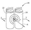
- FIG. 1is a schematic diagram of a first embodiment of a magnet assembly comprising two magnet cylinders constructed according to the principles of this invention
- FIG. 2 ais a horizontal cross-sectional view of the magnet assembly, taken along the plane of line 2 — 2 in FIG. 1, illustrating the field direction created in an operating region by the magnet cylinders in a first configuration;
- FIG. 2 bis a horizontal cross-sectional view of the magnet assembly, taken along the plane of line 2 — 2 in FIG. 1, illustrating the field direction created in an operating region by the magnet cylinders in a second configuration;
- FIG. 2 cis a horizontal cross-sectional view of the magnet assembly, taken along the plane of line 2 — 2 in FIG. 1, illustrating the field direction created in an operating region by the magnet cylinders in a third configuration;
- FIG. 2 dis a horizontal cross-sectional view of the magnet assembly, taken along the plane of line 2 — 2 in FIG. 1, illustrating the field direction created in an operating region by the magnet cylinders in a fourth configuration;
- FIG. 3is a schematic diagram of the magnet assembly of FIG. 1, rotated about an axis perpendicular to the plane of the magnet cylinders;
- FIG. 4is a schematic diagram of a second embodiment of a magnet assembly comprising three magnet cylinders constructed according to the principles of this invention
- FIG. 5 ais a horizontal cross-sectional view of the magnet assembly, taken along the plane of line 5 — 5 in FIG. 4, illustrating the field direction created in an operating region by the magnet cylinders in a first configuration;
- FIG. 5 bis a horizontal cross-sectional view of the magnet assembly, taken along the plane of line 5 — 5 in FIG. 4, illustrating the field direction created in an operating region by the magnet cylinders in a second configuration;
- FIG. 5 cis a horizontal cross-sectional view of the magnet assembly, taken along the plane of line 5 — 5 in FIG. 4, illustrating the field direction created in an operating region by the magnet cylinders in a third configuration;
- FIG. 5 dis a horizontal cross-sectional view of the magnet assembly, taken along the plane of line 5 — 5 in FIG. 4, illustrating the field direction created in an operating region by the magnet cylinders in a fourth configuration;
- FIG. 6is a schematic diagram of the magnet assembly of FIG. 4, rotated about an axis perpendicular to the plane of the magnet cylinders;
- FIG. 7is a perspective view of a stack of disk-shaped segments forming a magnet cylinder used in the magnet assemblies of the present invention.
- FIG. 8is horizontal cross-sectional view through one of the rotatable cylinders.
- FIG. 9 ais a front elevation schematic diagram showing two assemblies configured to surround a patient's head
- FIG. 9 bis a side elevation schematic diagram of the two assemblies shown in FIG. 9, after rotation of the two assemblies relative to the patient;
- FIG. 9 cis a top plan schematic diagram showing two assemblies configured to surround a patient's chest
- FIG. 9 dis a top plan schematic diagram showing two assemblies tilted to accommodate movement of an imaging C-arm
- FIG. 10is a schematic diagram of showing the arrangement of bi-planar imaging with two magnetic assemblies
- FIG. 11 ais a front elevation schematic diagram of a third embodiment of a magnet assembly constructed according to the principles of this invention, comprising at least three non-coplanar magnet cylinders;
- FIG. 11 bis a side elevation view of the magnet assembly of the third embodiment
- FIG. 12is a top plan view of a fourth embodiment of a magnet assembly constructed according to the principles of this invention, in which the magnetic rollers are in a non-parallel, planar configuration;
- FIG. 13is a perspective view of the magnet assembly of the fourth embodiment
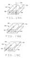
- FIG. 14is a top plan view of a fifth embodiment of a magnet assembly constructed according to the principles of this invention, in which the magnet rollers are in a non-parallel, planar configuration;
- FIG. 15is a perspective view of the magnet assembly of the fifth embodiment
- FIG. 16 ais top plan view of a six embodiment of a magnet assembly constructed according to the principles of this invention, with a patient disposed within the magnet assembly;
- FIG. 16 bis a top plan view of the magnet assembly of the sixth embodiment, without the patient;
- FIG. 16 cis an end elevation of the magnet assembly of the sixth embodiment, taken along the plane of line 16 c — 16 c in FIG. 16 b;
- FIG. 16 dis a side elevation view of the magnet assembly of the sixth embodiment, taken along the plane of line 16 d — 16 d in FIG. 16 c;
- FIG. 17 ais a top plan view of a seventh embodiment of a magnet assembly, comprising four magnets, but with only the two magnets disposed below the patient shown for clarity;
- FIG. 17 bis a transverse cross-sectional view of the magnetic assembly of the seventh embodiment
- FIG. 18 ais a top plan view of an eighth embodiment of a magnet assembly
- FIG. 18 bis a transverse cross-sectional view of the magnet assembly of the eighth embodiment.
- FIG. 19 ais a perspective view of a ninth embodiment of a magnet assembly constructed according to the principles of this invention, having a single rotatable magnet;
- FIG. 19 bis a perspective view of the ninth embodiment, with the single rotatable magnet in a different orientation than in FIG. 19 a ;
- FIG. 19 cis a perspective view of the ninth embodiment, with the single rotatable magnet in a different orientation than in FIGS. 19 a and 19 b.
- FIG. 1A first embodiment of a magnet assembly, indicated generally as 20 , is shown schematically in FIG. 1 .
- the assembly 20comprises two rotatably mounted, generally parallel magnet cylinders 22 and 24 .
- Each of the cylinders 22 and 24is made from a permanent magnetic material, such as NdBFe, or other magnetic material, preferably a high energy producing material with high coercivity. As described below is preferably jacketed in nonmagnetic stainless steel or wrapped in high strength carbon fiber or other strong nonmagnetic material.
- Each of the magnet cylinders 22 and 24is rotatable about its longitudinal axis.
- the magnet cylinders 22 and 24have a generally circular cross-section which is preferred because of ease of construction and because the magnets can be closely spaced and rotated without mutual interference.
- the cylinderscould have some other cross-sectional profile.
- each of the magnet cylinders 22 and 24is preferably uniformly magnetized in one direction, perpendicular to its longitudinal axis.
- the magnet assemblies shown and described hereinare particularly useful for magnetic medical procedures, such as navigation and aneurysm filling, the invention is not so limited, and the magnetic assemblies can be used in any application where a variable focused field is needed.
- the operating region Ois preferably a generally cubic region at least about 3 inches by about 3 inches by about 3 inches, and more preferably at least about 6 inches by about 6 inches by about 6 inches.
- the operating region Ois preferably at least about 7 inches from the magnet cylinders 22 and 24 , and more preferably at least about 10 inches from the magnet cylinders so that the operating region can be used to magnetically navigate magnetic materials anywhere in the body.
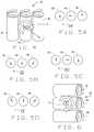
- the magnetic field created by the magnet cylinders 22 and 24is preferably at least 0.1 T. in any direction in the plane of the magnetization directions of the cylinders, by rotating the cylinders. This is illustrated in FIGS. 2 a , 2 b , 2 c , and 2 d , wherein the magnet cylinders 22 and 24 are shown in FIG. 2 a in a configuration that creates a magnetic field generally toward the magnet assembly, in FIG. 2 b in a configuration that creates a magnet field parallel to the plane of the cylinders, in FIG. 2 c in a configuration that creates a magnet field away from the magnet assembly, and in FIG.
- a magnetic field directioncan be created in the operating region in any direction. This is illustrated by comparing FIG. 1 and FIG. 3, where rotation of the magnet assembly 20 rotates the magnetic field direction in a plane parallel to the plane of the magnet cylinders.
- a magnetic fieldcan be created in the portion of the body containing the operating region O in any direction, without the need to translate the assembly 20 .
- exclusion zone around the magnet assembly 20is much smaller than with other types of magnets which must accommodate translations in all directions in the plane of the magnet in order to provide all directions of field lines.
- the assembly 20allows for better access to the patient, and better accommodates other equipment in the operating room, including imaging equipment such as bi-plane fluoroscopic imaging equipment.
- FIG. 4A second embodiment of a magnet assembly, indicated generally as 40 , is shown schematically in FIG. 4 .
- the assembly 40comprises three rotatably mounted, parallel magnet cylinders 42 , 44 , and 46 .
- the cylinders 42 , 44 , and 46are preferably arranged in a plane.
- Each of the cylinders 42 , 44 and 46is made from a permanent magnetic material, such as NdBFe, which as described below is preferably jacketed in stainless steel, carbon fibers or other strong, nonmagnetic material.
- the cylinders 42 , 44 and 46may have a circular cross-section, or a cross-section of some other shape.
- Each of the magnet cylinders 42 , 44 , and 46is rotatable about its longitudinal axis. Further, each of the magnet cylinders 42 , 44 , and 46 is preferably uniformly magnetized in one direction, perpendicular to its longitudinal axis. As described above with respect to assembly 20 , the magnetization may vary through the cylinders.
- the operating region Ois preferably a generally cubic region at least about 3 inches by about 3 inches by about 3 inches, and more preferably at least about 6 inches by about 6 inches by about 6 inches.
- the operating region Ois preferably at least about 7 inches from the magnetic cylinders, and more preferably at least about 10 inches from the magnet cylinders 42 , 44 and 46 so that it can be used to magnetically navigate magnetic materials anywhere in the body.
- the magnetic field created by the magnet cylinders 42 , 44 , and 46is preferably at least 0.1 T. in any direction in the plane of the magnetization directions of the cylinders, by rotating the cylinders. This is illustrated in FIGS. 5 a , 5 b , 5 c , and 5 d , wherein the magnet cylinders 42 , 44 and 46 are shown in FIG. 5 a in a configuration that creates a magnetic field generally toward the magnet assembly, in FIG. 5 b in a configuration that creates a magnet field parallel to the plane of the cylinders, in FIG. 5 c in a configuration that creates a magnet field away from the magnet assembly, and in FIG.
- a magnetic field directioncan be created in the operating region in any direction. This is illustrated by comparing FIG. 4 and FIG. 6, where rotation of the magnet assembly 40 rotates the magnetic field direction in a plane parallel to the plane of the magnet cylinders 42 , 44 and 46 .
- a magnetic fieldcan be created in the portion of the body containing the operating region O in any direction, without the need to translate the assembly 40 .
- exclusion zone around the magnet assembly 40is much smaller than with other types of magnets which must accommodate some translation of the magnet.
- the assembly 40allows for better access to the patient, and better accommodates other equipment in the operating room, including imaging equipment such as bi-plane fluoroscopic equipment.
- Each of the cylindersis preferably made from a stack of generally disk shaped permanent magnets 60 .
- Each of the disks 60has a diameter of between about 4 inches and about 6 inches, and is between about 1 ⁇ 2 and about 2 inches thick.
- the disks 60are stacked one upon the other, inside a cylindrical jacket 62 , made of stainless steel or carbon fibers.
- the jacket 62protects the disks 60 , and helps to maintain their integrity despite the large forces to which they are exposed as cylinders rotate relative to one another.
- the diskspreferably have a flat 64 one the exterior that engages an insert 66 inside the jacket 62 , to “key” the disks to facilitate rotation.
- the cylinders comprising the assemblies of this inventionare preferably rotatable about their longitudinal axis.
- the magnetization direction of the cylindersis preferably, but not necessarily uniform, and preferably, but not necessarily, perpendicular to the longitudinal axis.
- the rotation of the cylinders in the assembliesallows the magnet cylinders to create a magnetic field in the operating region in any direction from 0° to 360° in the plane of the magnetization directions of the cylinders.
- the magnet cylinders 42 , 44 , and 46can be arranged so that they create a strong magnetic field in front of the assembly, and in particular in the operating region O. In this configuration, there is very weak magnetic field behind the assembly. However, through rotation of the cylinders 42 , 44 , and 46 , this can be reversed, so that the strong field is behind the cylinders, and the weak field in front of the assembly, in effect “turning off” the magnet assembly from the perspective of the patient in front of the assembly.
- the magnet assemblywould be contained within a relatively compact enclosure.
- the rotation of the cylinders comprising the assembly, and the rotation of the assemblyallow the assembly to create a magnetic field in the operating region in the patient in any direction.
- the enclosurehides the movement of the magnet, and protects the patient, and other people and equipment in the operating room, from the magnet.
- Servo controlscan be provided to rotate the individual cylinders about their respective axes and to rotate the assembly about axis R.
- a directioncan be input into a control system by the physician, for example using a mouse on the two images of a bi-planar fluoroscopic imaging system, or using a joystick or keyboard.
- a computercan then calculate the best combination of rotational directions of the cylinder magnetizations and rotation of the assembly to achieve the desired direction. The computer can even account for a desired lead angle to ensure the proper navigation of a magnetic object in the body.
- An automatic advancercan also be provided and coordinated by the computer control, so that once the proper magnetic field is applied, the object is advanced in the desired direction.
- the magnet assembly of the present inventionfacilitates automating surgical procedures, and even facilitates telemedical procedures, where a procedure is performed by a physician remotely from the patient.
- a compound system with two planar magnetic assembliescan be provided.
- a compound system 100has two planar magnetic assemblies 102 and 104 arranged at an angle with respect to each other.
- the magnetic assemblies 102 and 104form a concavity for receiving a portion of the body, such as the head.
- the combination of the two planes of magnet cylindersallows a stronger magnetic field to be applied further from the magnet assemblies.
- FIGS. 9 a through 9 da compound system with two planar magnetic assemblies and can be provided.
- a compound system 100has two planar magnetic assemblies 102 and 104 arranged at an angle with respect to each other.
- the magnetic assemblies 102 and 104form a concavity for receiving a portion of the body, such as the head.
- the combination of the two planes of magnet cylindersallows a stronger magnetic field to be applied further from the magnet assemblies.
- a compound system 150has two planar magnetic assemblies 152 and 154 arranged in generally parallel orientation on opposite sides of a patient's body, for example on opposite sides of a patient's chest for conducting a cardiac procedure. Because each magnet assembly 152 and 154 only has to project a magnetic field halfway through the patient, and because each magnet assembly only has to contribute half of the desired magnetic field, the combined weight of the two magnet assemblies on opposite sides of the patient can be less than the weight of a single magnet assembly on one side of the patient projecting the same magnetic field strength.
- FIG. 10shows a compound assembly 200 , comprising two planar magnetic assemblies 202 and 204 , arranged for bi-planar fluoroscopic imaging of the procedure site.
- Imaging plates 206 and 208such as an amorphous silicon imaging plates (which are substantially unaffected by magnetic fields), are disposed in front of each of the magnetic assemblies 203 and 204 , respectively.
- Imaging beam sourcessuch as x-ray sources 210 and 212 are disposed to project an imaging beam through the patient and onto the imaging plates 206 and 208 .
- magnetic navigationcan be provided while allowing access for fluoroscopic imaging.
- a third embodiment of a magnet assembly constructed according to the principles of this invention as indicated generallyis 220 in FIGS. 11 a and 11 b .
- the assembly 220comprises at least three parallel, rotatably mounted magnet cylinders 222 , 224 and 226 .
- Each of the magnet cylinders 222 , 224 and 226is preferably constructed as described above, with a magnetization direction generally perpendicular to the longitudinal axis of the cylinder.
- the cylindersare arranged so they are not coplanar but instead form a concave portion for receiving a portion of the patient's body.
- the cylinders 222 , 224 and 226form a concavity for receiving the patient's head.
- Rotation of the cylinders 222 , 224 , and 226 and rotation of the assemblyallows the creation of a magnetic field in any selected direction in an operating region in the part of the patient in the space between the cylinders 222 , 224 and 226 .
- a fourth embodiment of a magnet assembly constructed according to the principles of this inventionis indicated generally as 250 in FIGS. 12 and 13.
- the assembly 250comprises three magnet cylinders 252 , 254 , and 256 , whose longitudinal axes are coplanar.
- Each of the magnet cylindersis preferably constructed as described above, with a magnetization direction generally perpendicular to the longitudinal axis.
- rotation of the cylinders 252 , 254 , and 256can project a magnetic field in an operating region spaced from the plane of the cylinders in any direction.
- the magnet assembly 250can provide a navigating magnetic field in any direction without any translation or rotation of the assembly, but simply a rotation of the cylinders 252 , 254 , and 256 comprising the assembly.
- a fifth embodiment of a magnet assembly constructed according to the principles of this inventionis indicated generally as 300 in FIGS. 14 and 15.
- the assembly 300comprises three magnet cylinders 302 , 304 , and 306 , arranged generally in a “Y” shaped configuration.
- Each of the magnet cylindersis preferably constructed as described above, with a magnetization direction generally perpendicular to the longitudinal axis.
- the magnet cylinders 302 , 304 , and 306may be coplanar, or as shown in FIGS. 14 and 15, the magnet cylinders may be arranged in a pyramid, with one end of each of magnet cylinders at the apex of the pyramid. In this arrangement, the cylinders form a concave space for receiving a portion the patient's body.
- the magnet assembly 300can provide a navigating magnetic field in any direction without any translation or rotation of the assembly, but simply a rotation of the cylinders 302 , 304 , and 306 .
- a sixth embodiment of a magnet assembly constructed according to the principles of this inventionis indicated generally as 350 in FIGS. 16 a through 16 d .
- the magnet assemblycomprises four magnet cylinders 352 , 354 , 356 , and 358 .
- the first magnet cylinder 352extends generally transversely across the top of the user's body, below the chest.
- the second magnet cylinder 354extends generally transversely below the patient's body, above the shoulders.
- the third magnet cylinder 356extend generally parallel with the longitudinal of the patient, above the right side of the patient's chest.
- the fourth magnet cylinder 358extends generally parallel with the longitudinal axis of the patient, below the right side of the patient's chest.
- the left end of the cylinder 352extends over the bottom end of the cylinder 356 , and the cylinder slopes downwardly toward the right side.
- the right end of the second magnet cylinder 354is above the upper end cylinder 358 , and the cylinder slopes downwardly toward the left side.
- Each of the cylindersis preferably constructed as described above, with the magnetization direction generally perpendicular to the longitudinal axis of the cylinder.
- the first and second cylinders 352 and 354 , and the third and fourth cylinders 356 and 358are arranged on opposite sides of the heart while leaving the heart uncovered so that the heart can be imaged during the procedure. Rotation of the cylinders 352 , 354 , 336 and 358 allows the creation of a magnetic field in any selected direction in the operating region (the heart in FIGS. 16 a - 16 d ).
- FIGS. 17 a and 17 bAn eighth embodiment of a magnet assembly constructed according to the principles of this invention is indicated generally as 400 in FIGS. 17 a and 17 b .
- the magnet assembly 400comprises first and second cylinders 402 and 404 beneath the patient, the first roller extending generally below the shoulders at the top of the chest, and the second cylinder extending generally below the rib cage at the bottom of the chest.
- the cylindersare constructed as described above, with the magnetization direction generally perpendicular to the longitudinal axis of the cylinder.
- the magnet assembly 400further comprises third and fourth rollers 406 and 408 (shown only in FIG. 17 b ), extending parallel to the longitudinal axis of the patient, on either side of the patient, above the patient's arms.
- the cylinders 402 and 404are spaced such that an imaging beam source below the patient, and an imaging plate, such as an amorphous silicon imaging plate 410 above the patient, can image the heart H without interference from the cylinders.
- Rotation of the cylinders 402 , 404 , 406 , 408allows the creation of a magnetic field, in any selected direction in the operating region (the heart in FIGS. 17 a and 17 b ).
- FIGS. 18 a and 18 bAn eight embodiment of a magnet assembly constructed according to the principles of this invention is indicated generally as 450 in FIGS. 18 a and 18 b .
- the assembly 450is similar in construction to assembly 400 , comprising first and second cylinders 452 and 454 , extending generally transversely across the patient's body. However, unlike assembly 400 wherein the first and second cylinders 402 and 404 are below the patient, cylinders 452 and 454 are above the patient.
- the magnet assembly 450also includes third and fourth magnet cylinders 456 and 458 , which like cylinders 406 and 408 of assembly 400 , extend parallel to the longitudinal axis of the patient, on either side of the patient above the patient's arms.
- the cylinders 452 and 454are spaced such that an imaging beam source below the patient, and an imaging plate, such as an amorphous silicon imaging plate 460 above the patient, can image the heart without interference from the cylinders.
- the assembly 450is particularly adapted to be mounted on a ceiling support, and lowered into position over the patient, and raised away from the patient after completion of the procedure. Rotation of the cylinders 452 , 454 , 456 and 458 allow the creation of a magnetic field in any selected direction of the operating region (the heart in FIGS. 18 a and 18 b ).
- a ninth embodiment of a magnet assembly constructed according to the principles of this inventionis indicated generally as 500 in FIGS. 19 a , 19 b , and 19 c .
- the magnet assemblycomprises at least two magnets, at least one of which is rotatable with respect to the other to change the direction and/or intensity of the magnetic field in an operating region spaced from the face 510 of the assembly, preferably along a central perpendicular axis 508 .
- the magnets 502 and 504are stationery, and magnet 506 is mounted for rotation relative to the magnets 502 and 504 .
- the magnets 502 and 504are formed in one piece, with an opening for receiving the magnet 506 , but the invention is not so limited, and magnets 502 and 504 can be made in separate pieces.
- the magnet 502is preferably magnetized parallel to the axis 508 , and perpendicular to the face 510 of the assembly.
- the magnet 504is likewise preferably magnetized parallel to the axis 508 , and perpendicular to the face 510 of the assembly, but in a direction opposite to magnet 502 .
- the magnet 506is preferably cylindrical (although it could be some other shape), and mounted for rotation about its longitudinal axis.
- the magnet 506is preferably magnetized perpendicular to its axis of rotation.
- the rotation of the magnet 506 relative to the magnets 502 and 504changes the magnetic field projected by the assembly.
- a magnetic field of sufficient strength for magnetic navigation of a magnet medical devicecan be projected in virtually any direction at an operating point space from the face 510 of the assembly. Operation
- a magnetically responsive medical deviceis introduced into the body.
- This devicemay be a cannula, catheter, endoscope, or other device that is magnetically responsive through the inclusion of an electromagnet, a permanent magnet, or a permeable magnetic material.
- the deviceis oriented in a desired direction by applying a magnetic field in the appropriate direction to cause the device to align in the desired direction.
- the applied fieldmay be slightly different from the desired direction because of the properties of the device.
- the navigationis computer controlled, the computer can automatically take the properties of the device into account in determining the direction of the magnet field to apply.
- the magnet cylindersare turned and the magnet assembly is turned (where necessary) until the device is in the desired direction.
- the devicecan then be advanced, either manually or automatically, using an advancer.
- the deviceis advanced until a change of direction is desired.
- the assemblyis used to apply a magnetic field to cause the device to orient in the new desired direction, and the device again advanced. This is repeated until the device is in the desired location.
Landscapes
- Health & Medical Sciences (AREA)
- Life Sciences & Earth Sciences (AREA)
- Surgery (AREA)
- Engineering & Computer Science (AREA)
- Animal Behavior & Ethology (AREA)
- Veterinary Medicine (AREA)
- Biomedical Technology (AREA)
- Heart & Thoracic Surgery (AREA)
- Medical Informatics (AREA)
- Molecular Biology (AREA)
- Nuclear Medicine, Radiotherapy & Molecular Imaging (AREA)
- General Health & Medical Sciences (AREA)
- Public Health (AREA)
- Robotics (AREA)
- Physics & Mathematics (AREA)
- Biophysics (AREA)
- Optics & Photonics (AREA)
- Pathology (AREA)
- Radiology & Medical Imaging (AREA)
- Magnetic Resonance Imaging Apparatus (AREA)
- Magnetic Treatment Devices (AREA)
Abstract
Description
Claims (35)
Priority Applications (3)
| Application Number | Priority Date | Filing Date | Title |
|---|---|---|---|
| US09/695,119US6537196B1 (en) | 2000-10-24 | 2000-10-24 | Magnet assembly with variable field directions and methods of magnetically navigating medical objects |
| AU2001292964AAU2001292964A1 (en) | 2000-10-24 | 2001-09-21 | Magnet assembly with variable field directions and methods of magnetically navigating medical objects |
| PCT/US2001/029666WO2002034131A1 (en) | 2000-10-24 | 2001-09-21 | Magnet assembly with variable field directions and methods of magnetically navigating medical objects |
Applications Claiming Priority (1)
| Application Number | Priority Date | Filing Date | Title |
|---|---|---|---|
| US09/695,119US6537196B1 (en) | 2000-10-24 | 2000-10-24 | Magnet assembly with variable field directions and methods of magnetically navigating medical objects |
Publications (1)
| Publication Number | Publication Date |
|---|---|
| US6537196B1true US6537196B1 (en) | 2003-03-25 |
Family
ID=24791651
Family Applications (1)
| Application Number | Title | Priority Date | Filing Date |
|---|---|---|---|
| US09/695,119Expired - Fee RelatedUS6537196B1 (en) | 2000-10-24 | 2000-10-24 | Magnet assembly with variable field directions and methods of magnetically navigating medical objects |
Country Status (3)
| Country | Link |
|---|---|
| US (1) | US6537196B1 (en) |
| AU (1) | AU2001292964A1 (en) |
| WO (1) | WO2002034131A1 (en) |
Cited By (219)
| Publication number | Priority date | Publication date | Assignee | Title |
|---|---|---|---|---|
| US20020177789A1 (en)* | 2001-05-06 | 2002-11-28 | Ferry Steven J. | System and methods for advancing a catheter |
| US20030149332A1 (en)* | 2002-02-05 | 2003-08-07 | Alicea Pedro J. | Pain eliminator |
| US20040019447A1 (en)* | 2002-07-16 | 2004-01-29 | Yehoshua Shachar | Apparatus and method for catheter guidance control and imaging |
| US20040169316A1 (en)* | 2002-03-28 | 2004-09-02 | Siliconix Taiwan Ltd. | Encapsulation method and leadframe for leadless semiconductor packages |
| US20050096589A1 (en)* | 2003-10-20 | 2005-05-05 | Yehoshua Shachar | System and method for radar-assisted catheter guidance and control |
| US20050113812A1 (en)* | 2003-09-16 | 2005-05-26 | Viswanathan Raju R. | User interface for remote control of medical devices |
| US20050288576A1 (en)* | 2002-06-10 | 2005-12-29 | Stephan Fegert | Method and apparatus for control and location of an instrument or appliance |
| US20060036163A1 (en)* | 2004-07-19 | 2006-02-16 | Viswanathan Raju R | Method of, and apparatus for, controlling medical navigation systems |
| US20060079745A1 (en)* | 2004-10-07 | 2006-04-13 | Viswanathan Raju R | Surgical navigation with overlay on anatomical images |
| US20060144408A1 (en)* | 2004-07-23 | 2006-07-06 | Ferry Steven J | Micro-catheter device and method of using same |
| US20060144407A1 (en)* | 2004-07-20 | 2006-07-06 | Anthony Aliberto | Magnetic navigation manipulation apparatus |
| US20060269108A1 (en)* | 2005-02-07 | 2006-11-30 | Viswanathan Raju R | Registration of three dimensional image data to 2D-image-derived data |
| US20060270915A1 (en)* | 2005-01-11 | 2006-11-30 | Ritter Rogers C | Navigation using sensed physiological data as feedback |
| US20060276867A1 (en)* | 2005-06-02 | 2006-12-07 | Viswanathan Raju R | Methods and devices for mapping the ventricle for pacing lead placement and therapy delivery |
| US20060281990A1 (en)* | 2005-05-06 | 2006-12-14 | Viswanathan Raju R | User interfaces and navigation methods for vascular navigation |
| US20060278246A1 (en)* | 2003-05-21 | 2006-12-14 | Michael Eng | Electrophysiology catheter |
| US20060281989A1 (en)* | 2005-05-06 | 2006-12-14 | Viswanathan Raju R | Voice controlled user interface for remote navigation systems |
| US20070016131A1 (en)* | 2005-07-12 | 2007-01-18 | Munger Gareth T | Flexible magnets for navigable medical devices |
| US20070016006A1 (en)* | 2005-05-27 | 2007-01-18 | Yehoshua Shachar | Apparatus and method for shaped magnetic field control for catheter, guidance, control, and imaging |
| US20070021742A1 (en)* | 2005-07-18 | 2007-01-25 | Viswanathan Raju R | Estimation of contact force by a medical device |
| US20070019330A1 (en)* | 2005-07-12 | 2007-01-25 | Charles Wolfersberger | Apparatus for pivotally orienting a projection device |
| US20070021731A1 (en)* | 1997-11-12 | 2007-01-25 | Garibaldi Jeffrey M | Method of and apparatus for navigating medical devices in body lumens |
| US20070030958A1 (en)* | 2005-07-15 | 2007-02-08 | Munger Gareth T | Magnetically shielded x-ray tube |
| US20070038410A1 (en)* | 2005-08-10 | 2007-02-15 | Ilker Tunay | Method and apparatus for dynamic magnetic field control using multiple magnets |
| US20070038064A1 (en)* | 2005-07-08 | 2007-02-15 | Creighton Francis M Iv | Magnetic navigation and imaging system |
| US20070038065A1 (en)* | 2005-07-07 | 2007-02-15 | Creighton Francis M Iv | Operation of a remote medical navigation system using ultrasound image |
| US20070038074A1 (en)* | 1998-02-09 | 2007-02-15 | Ritter Rogers C | Method and device for locating magnetic implant source field |
| US20070043455A1 (en)* | 2005-07-26 | 2007-02-22 | Viswanathan Raju R | Apparatus and methods for automated sequential movement control for operation of a remote navigation system |
| US20070040670A1 (en)* | 2005-07-26 | 2007-02-22 | Viswanathan Raju R | System and network for remote medical procedures |
| US20070055124A1 (en)* | 2005-09-01 | 2007-03-08 | Viswanathan Raju R | Method and system for optimizing left-heart lead placement |
| US20070060962A1 (en)* | 2005-07-26 | 2007-03-15 | Carlo Pappone | Apparatus and methods for cardiac resynchronization therapy and cardiac contractility modulation |
| US20070060829A1 (en)* | 2005-07-21 | 2007-03-15 | Carlo Pappone | Method of finding the source of and treating cardiac arrhythmias |
| US20070060966A1 (en)* | 2005-07-11 | 2007-03-15 | Carlo Pappone | Method of treating cardiac arrhythmias |
| US20070062546A1 (en)* | 2005-06-02 | 2007-03-22 | Viswanathan Raju R | Electrophysiology catheter and system for gentle and firm wall contact |
| US20070062547A1 (en)* | 2005-07-21 | 2007-03-22 | Carlo Pappone | Systems for and methods of tissue ablation |
| US20070083103A1 (en)* | 2005-09-28 | 2007-04-12 | Jan Boese | Arrangement for acquiring an object |
| US20070088077A1 (en)* | 1991-02-26 | 2007-04-19 | Plasse Terry F | Appetite stimulation and reduction of weight loss in patients suffering from symptomatic hiv infection |
| US20070088197A1 (en)* | 2000-02-16 | 2007-04-19 | Sterotaxis, Inc. | Magnetic medical devices with changeable magnetic moments and method of navigating magnetic medical devices with changeable magnetic moments |
| US20070149946A1 (en)* | 2005-12-07 | 2007-06-28 | Viswanathan Raju R | Advancer system for coaxial medical devices |
| US20070161882A1 (en)* | 2006-01-06 | 2007-07-12 | Carlo Pappone | Electrophysiology catheter and system for gentle and firm wall contact |
| US20070161888A1 (en)* | 2005-12-30 | 2007-07-12 | Sherman Jason T | System and method for registering a bone of a patient with a computer assisted orthopaedic surgery system |
| US20070167703A1 (en)* | 2005-12-30 | 2007-07-19 | Sherman Jason T | Method for determining a position of a magnetic source |
| US20070167741A1 (en)* | 2005-12-30 | 2007-07-19 | Sherman Jason T | Apparatus and method for registering a bone of a patient with a computer assisted orthopaedic surgery system |
| US20070167720A1 (en)* | 2005-12-06 | 2007-07-19 | Viswanathan Raju R | Smart card control of medical devices |
| US20070163367A1 (en)* | 2005-12-30 | 2007-07-19 | Sherman Jason T | Magnetic sensor array |
| US20070179333A1 (en)* | 2006-01-31 | 2007-08-02 | U.S. Wax & Polymer, Inc. | Magnetic field applicator system |
| US20070197899A1 (en)* | 2006-01-17 | 2007-08-23 | Ritter Rogers C | Apparatus and method for magnetic navigation using boost magnets |
| US20070197891A1 (en)* | 2006-02-23 | 2007-08-23 | Yehoshua Shachar | Apparatus for magnetically deployable catheter with MOSFET sensor and method for mapping and ablation |
| US20070197906A1 (en)* | 2006-01-24 | 2007-08-23 | Ritter Rogers C | Magnetic field shape-adjustable medical device and method of using the same |
| US20070250041A1 (en)* | 2006-04-19 | 2007-10-25 | Werp Peter R | Extendable Interventional Medical Devices |
| US20070255273A1 (en)* | 2006-04-29 | 2007-11-01 | Board Of Regents, The University Of Texas System | Devices for use in Transluminal and Endoluminal Surgery |
| US20070282156A1 (en)* | 2004-06-16 | 2007-12-06 | Maurits Konings | Apparatus For Generating Electric Current Field In The Human Body And Method For The Use Thereof |
| US20070287909A1 (en)* | 1998-08-07 | 2007-12-13 | Stereotaxis, Inc. | Method and apparatus for magnetically controlling catheters in body lumens and cavities |
| US20080006280A1 (en)* | 2004-07-20 | 2008-01-10 | Anthony Aliberto | Magnetic navigation maneuvering sheath |
| US20080015427A1 (en)* | 2006-06-30 | 2008-01-17 | Nathan Kastelein | System and network for remote medical procedures |
| US20080015670A1 (en)* | 2006-01-17 | 2008-01-17 | Carlo Pappone | Methods and devices for cardiac ablation |
| US20080016677A1 (en)* | 2002-01-23 | 2008-01-24 | Stereotaxis, Inc. | Rotating and pivoting magnet for magnetic navigation |
| US20080039830A1 (en)* | 2006-08-14 | 2008-02-14 | Munger Gareth T | Method and Apparatus for Ablative Recanalization of Blocked Vasculature |
| US20080045892A1 (en)* | 2001-05-06 | 2008-02-21 | Ferry Steven J | System and Methods for Advancing a Catheter |
| US20080047568A1 (en)* | 1999-10-04 | 2008-02-28 | Ritter Rogers C | Method for Safely and Efficiently Navigating Magnetic Devices in the Body |
| US20080055239A1 (en)* | 2006-09-06 | 2008-03-06 | Garibaldi Jeffrey M | Global Input Device for Multiple Computer-Controlled Medical Systems |
| US20080059598A1 (en)* | 2006-09-06 | 2008-03-06 | Garibaldi Jeffrey M | Coordinated Control for Multiple Computer-Controlled Medical Systems |
| US20080058609A1 (en)* | 2006-09-06 | 2008-03-06 | Stereotaxis, Inc. | Workflow driven method of performing multi-step medical procedures |
| US20080065061A1 (en)* | 2006-09-08 | 2008-03-13 | Viswanathan Raju R | Impedance-Based Cardiac Therapy Planning Method with a Remote Surgical Navigation System |
| US20080064969A1 (en)* | 2006-09-11 | 2008-03-13 | Nathan Kastelein | Automated Mapping of Anatomical Features of Heart Chambers |
| US20080077007A1 (en)* | 2002-06-28 | 2008-03-27 | Hastings Roger N | Method of Navigating Medical Devices in the Presence of Radiopaque Material |
| US20080097200A1 (en)* | 2006-10-20 | 2008-04-24 | Blume Walter M | Location and Display of Occluded Portions of Vessels on 3-D Angiographic Images |
| US20080132910A1 (en)* | 2006-11-07 | 2008-06-05 | Carlo Pappone | Control for a Remote Navigation System |
| US20080154127A1 (en)* | 2006-12-21 | 2008-06-26 | Disilvestro Mark R | Method and system for registering a bone of a patient with a computer assisted orthopaedic surgery system |
| US20080200913A1 (en)* | 2007-02-07 | 2008-08-21 | Viswanathan Raju R | Single Catheter Navigation for Diagnosis and Treatment of Arrhythmias |
| US20080228065A1 (en)* | 2007-03-13 | 2008-09-18 | Viswanathan Raju R | System and Method for Registration of Localization and Imaging Systems for Navigational Control of Medical Devices |
| US20080228068A1 (en)* | 2007-03-13 | 2008-09-18 | Viswanathan Raju R | Automated Surgical Navigation with Electro-Anatomical and Pre-Operative Image Data |
| US20080249395A1 (en)* | 2007-04-06 | 2008-10-09 | Yehoshua Shachar | Method and apparatus for controlling catheter positioning and orientation |
| US20080269779A1 (en)* | 2003-12-02 | 2008-10-30 | Board Of Regents, The University Of Texas System | Surgical anchor and system |
| US20080287909A1 (en)* | 2007-05-17 | 2008-11-20 | Viswanathan Raju R | Method and apparatus for intra-chamber needle injection treatment |
| US20080292901A1 (en)* | 2007-05-24 | 2008-11-27 | Hon Hai Precision Industry Co., Ltd. | Magnesium alloy and thin workpiece made of the same |
| US20080294232A1 (en)* | 2007-05-22 | 2008-11-27 | Viswanathan Raju R | Magnetic cell delivery |
| US20090012821A1 (en)* | 2007-07-06 | 2009-01-08 | Guy Besson | Management of live remote medical display |
| US20090062646A1 (en)* | 2005-07-07 | 2009-03-05 | Creighton Iv Francis M | Operation of a remote medical navigation system using ultrasound image |
| US20090082722A1 (en)* | 2007-08-21 | 2009-03-26 | Munger Gareth T | Remote navigation advancer devices and methods of use |
| US20090105579A1 (en)* | 2007-10-19 | 2009-04-23 | Garibaldi Jeffrey M | Method and apparatus for remotely controlled navigation using diagnostically enhanced intra-operative three-dimensional image data |
| US20090112207A1 (en)* | 2007-10-30 | 2009-04-30 | Blair Walker | Skeletal manipulation method |
| US20090131927A1 (en)* | 2007-11-20 | 2009-05-21 | Nathan Kastelein | Method and apparatus for remote detection of rf ablation |
| US20090131798A1 (en)* | 2007-11-19 | 2009-05-21 | Minar Christopher D | Method and apparatus for intravascular imaging and occlusion crossing |
| US7543239B2 (en) | 2004-06-04 | 2009-06-02 | Stereotaxis, Inc. | User interface for remote control of medical devices |
| US20090177032A1 (en)* | 1999-04-14 | 2009-07-09 | Garibaldi Jeffrey M | Method and apparatus for magnetically controlling endoscopes in body lumens and cavities |
| US20090177037A1 (en)* | 2007-06-27 | 2009-07-09 | Viswanathan Raju R | Remote control of medical devices using real time location data |
| US20090275828A1 (en)* | 2008-05-01 | 2009-11-05 | Magnetecs, Inc. | Method and apparatus for creating a high resolution map of the electrical and mechanical properties of the heart |
| US20100069733A1 (en)* | 2008-09-05 | 2010-03-18 | Nathan Kastelein | Electrophysiology catheter with electrode loop |
| US20100130854A1 (en)* | 2008-11-25 | 2010-05-27 | Magnetecs, Inc. | System and method for a catheter impedance seeking device |
| US20100163061A1 (en)* | 2000-04-11 | 2010-07-01 | Creighton Francis M | Magnets with varying magnetization direction and method of making such magnets |
| US7751867B2 (en) | 2004-12-20 | 2010-07-06 | Stereotaxis, Inc. | Contact over-torque with three-dimensional anatomical data |
| US20100222669A1 (en)* | 2006-08-23 | 2010-09-02 | William Flickinger | Medical device guide |
| US20100244828A1 (en)* | 2007-08-31 | 2010-09-30 | Alexander Pines | Adjustable permanent magnet assembly for nmr and mri |
| US7818076B2 (en) | 2005-07-26 | 2010-10-19 | Stereotaxis, Inc. | Method and apparatus for multi-system remote surgical navigation from a single control center |
| US20100298845A1 (en)* | 2009-05-25 | 2010-11-25 | Kidd Brian L | Remote manipulator device |
| US20100305502A1 (en)* | 2001-05-06 | 2010-12-02 | Ferry Steven J | Systems and methods for medical device advancement and rotation |
| US20110046618A1 (en)* | 2009-08-04 | 2011-02-24 | Minar Christopher D | Methods and systems for treating occluded blood vessels and other body cannula |
| US20110087224A1 (en)* | 2009-10-09 | 2011-04-14 | Cadeddu Jeffrey A | Magnetic surgical sled with variable arm |
| US20110092808A1 (en)* | 2009-10-20 | 2011-04-21 | Magnetecs, Inc. | Method for acquiring high density mapping data with a catheter guidance system |
| US20110091853A1 (en)* | 2009-10-20 | 2011-04-21 | Magnetecs, Inc. | Method for simulating a catheter guidance system for control, development and training applications |
| US20110112396A1 (en)* | 2009-11-09 | 2011-05-12 | Magnetecs, Inc. | System and method for targeting catheter electrodes |
| US20110130718A1 (en)* | 2009-05-25 | 2011-06-02 | Kidd Brian L | Remote Manipulator Device |
| US7961924B2 (en) | 2006-08-21 | 2011-06-14 | Stereotaxis, Inc. | Method of three-dimensional device localization using single-plane imaging |
| US7966059B2 (en) | 1999-10-04 | 2011-06-21 | Stereotaxis, Inc. | Rotating and pivoting magnet for magnetic navigation |
| US20110285488A1 (en)* | 2010-05-19 | 2011-11-24 | The Board Of Regents Of The University Of Texas System | Magnetic Throttling and Control: Magnetic Control |
| US20110295108A1 (en)* | 2007-11-26 | 2011-12-01 | C.R. Bard, Inc. | Apparatus for use with needle insertion guidance system |
| US8196590B2 (en) | 2003-05-02 | 2012-06-12 | Stereotaxis, Inc. | Variable magnetic moment MR navigation |
| US8231618B2 (en) | 2007-11-05 | 2012-07-31 | Stereotaxis, Inc. | Magnetically guided energy delivery apparatus |
| US8242972B2 (en) | 2006-09-06 | 2012-08-14 | Stereotaxis, Inc. | System state driven display for medical procedures |
| US8308628B2 (en) | 2009-11-02 | 2012-11-13 | Pulse Therapeutics, Inc. | Magnetic-based systems for treating occluded vessels |
| US8419681B2 (en) | 2002-11-18 | 2013-04-16 | Stereotaxis, Inc. | Magnetically navigable balloon catheters |
| US8437833B2 (en) | 2008-10-07 | 2013-05-07 | Bard Access Systems, Inc. | Percutaneous magnetic gastrostomy |
| US20130158659A1 (en)* | 2011-12-20 | 2013-06-20 | Richard A. Bergs | Medical Devices, Apparatuses, Systems, and Methods With Configurations for Shaping Magnetic-Fields and Interactions |
| US8478382B2 (en) | 2008-02-11 | 2013-07-02 | C. R. Bard, Inc. | Systems and methods for positioning a catheter |
| US8512256B2 (en) | 2006-10-23 | 2013-08-20 | Bard Access Systems, Inc. | Method of locating the tip of a central venous catheter |
| US8774907B2 (en) | 2006-10-23 | 2014-07-08 | Bard Access Systems, Inc. | Method of locating the tip of a central venous catheter |
| US8781555B2 (en) | 2007-11-26 | 2014-07-15 | C. R. Bard, Inc. | System for placement of a catheter including a signal-generating stylet |
| US8784336B2 (en) | 2005-08-24 | 2014-07-22 | C. R. Bard, Inc. | Stylet apparatuses and methods of manufacture |
| US8801693B2 (en) | 2010-10-29 | 2014-08-12 | C. R. Bard, Inc. | Bioimpedance-assisted placement of a medical device |
| US8849382B2 (en) | 2007-11-26 | 2014-09-30 | C. R. Bard, Inc. | Apparatus and display methods relating to intravascular placement of a catheter |
| US8852236B2 (en) | 2004-07-02 | 2014-10-07 | Ellipse Technologies, Inc. | Expandable rod system to treat scoliosis and method of using the same |
| CN104244797A (en)* | 2012-05-07 | 2014-12-24 | 奥林巴斯医疗株式会社 | Magnetic field generation device, and capsule-type medical device guide system |
| US8936542B1 (en) | 2011-03-03 | 2015-01-20 | Cyclomagnetics Llc | Cyclomagnetic therapy |
| USD724745S1 (en) | 2011-08-09 | 2015-03-17 | C. R. Bard, Inc. | Cap for an ultrasound probe |
| US9125578B2 (en) | 2009-06-12 | 2015-09-08 | Bard Access Systems, Inc. | Apparatus and method for catheter navigation and tip location |
| US9211107B2 (en) | 2011-11-07 | 2015-12-15 | C. R. Bard, Inc. | Ruggedized ultrasound hydrogel insert |
| US9248043B2 (en) | 2010-06-30 | 2016-02-02 | Ellipse Technologies, Inc. | External adjustment device for distraction device |
| USD754357S1 (en) | 2011-08-09 | 2016-04-19 | C. R. Bard, Inc. | Ultrasound probe head |
| US9339206B2 (en) | 2009-06-12 | 2016-05-17 | Bard Access Systems, Inc. | Adaptor for endovascular electrocardiography |
| US9339285B2 (en) | 2013-03-12 | 2016-05-17 | Levita Magnetics International Corp. | Grasper with magnetically-controlled positioning |
| US20160252369A1 (en)* | 2003-10-14 | 2016-09-01 | Merlin Technology, Inc. | Tracking positions of personnel, vehicles, and inanimate objects |
| US9445734B2 (en) | 2009-06-12 | 2016-09-20 | Bard Access Systems, Inc. | Devices and methods for endovascular electrography |
| US9492097B2 (en) | 2007-11-26 | 2016-11-15 | C. R. Bard, Inc. | Needle length determination and calibration for insertion guidance system |
| US9521961B2 (en) | 2007-11-26 | 2016-12-20 | C. R. Bard, Inc. | Systems and methods for guiding a medical instrument |
| US9532724B2 (en) | 2009-06-12 | 2017-01-03 | Bard Access Systems, Inc. | Apparatus and method for catheter navigation using endovascular energy mapping |
| US9554716B2 (en) | 2007-11-26 | 2017-01-31 | C. R. Bard, Inc. | Insertion guidance system for needles and medical components |
| US9636031B2 (en) | 2007-11-26 | 2017-05-02 | C.R. Bard, Inc. | Stylets for use with apparatus for intravascular placement of a catheter |
| US9649048B2 (en) | 2007-11-26 | 2017-05-16 | C. R. Bard, Inc. | Systems and methods for breaching a sterile field for intravascular placement of a catheter |
| US9681823B2 (en) | 2007-11-26 | 2017-06-20 | C. R. Bard, Inc. | Integrated system for intravascular placement of a catheter |
| US9839372B2 (en) | 2014-02-06 | 2017-12-12 | C. R. Bard, Inc. | Systems and methods for guidance and placement of an intravascular device |
| US9844391B2 (en) | 2009-02-06 | 2017-12-19 | Levita Magnetics International Corp. | Remote traction and guidance system for mini-invasive surgery |
| US9883878B2 (en) | 2012-05-15 | 2018-02-06 | Pulse Therapeutics, Inc. | Magnetic-based systems and methods for manipulation of magnetic particles |
| US9901714B2 (en) | 2008-08-22 | 2018-02-27 | C. R. Bard, Inc. | Catheter assembly including ECG sensor and magnetic assemblies |
| US10010370B2 (en) | 2013-03-14 | 2018-07-03 | Levita Magnetics International Corp. | Magnetic control assemblies and systems therefor |
| US10016220B2 (en) | 2011-11-01 | 2018-07-10 | Nuvasive Specialized Orthopedics, Inc. | Adjustable magnetic devices and methods of using same |
| US10039661B2 (en) | 2006-10-20 | 2018-08-07 | Nuvasive Specialized Orthopedics, Inc. | Adjustable implant and method of use |
| US10046139B2 (en) | 2010-08-20 | 2018-08-14 | C. R. Bard, Inc. | Reconfirmation of ECG-assisted catheter tip placement |
| US10172669B2 (en) | 2009-10-09 | 2019-01-08 | Ethicon Llc | Surgical instrument comprising an energy trigger lockout |
| US10238427B2 (en) | 2015-02-19 | 2019-03-26 | Nuvasive Specialized Orthopedics, Inc. | Systems and methods for vertebral adjustment |
| US10271885B2 (en) | 2014-12-26 | 2019-04-30 | Nuvasive Specialized Orthopedics, Inc. | Systems and methods for distraction |
| US10314638B2 (en) | 2015-04-07 | 2019-06-11 | Ethicon Llc | Articulating radio frequency (RF) tissue seal with articulating state sensing |
| US10349890B2 (en) | 2015-06-26 | 2019-07-16 | C. R. Bard, Inc. | Connector interface for ECG-based catheter positioning system |
| US10405891B2 (en) | 2010-08-09 | 2019-09-10 | Nuvasive Specialized Orthopedics, Inc. | Maintenance feature in magnetic implant |
| US10449330B2 (en) | 2007-11-26 | 2019-10-22 | C. R. Bard, Inc. | Magnetic element-equipped needle assemblies |
| US10478232B2 (en) | 2009-04-29 | 2019-11-19 | Nuvasive Specialized Orthopedics, Inc. | Interspinous process device and method |
| WO2019219207A1 (en) | 2018-05-18 | 2019-11-21 | MAX-PLANCK-Gesellschaft zur Förderung der Wissenschaften e.V. | Magnetic field generator |
| US10517643B2 (en) | 2009-02-23 | 2019-12-31 | Nuvasive Specialized Orthopedics, Inc. | Non-invasive adjustable distraction system |
| US10524691B2 (en) | 2007-11-26 | 2020-01-07 | C. R. Bard, Inc. | Needle assembly including an aligned magnetic element |
| US10537348B2 (en) | 2014-01-21 | 2020-01-21 | Levita Magnetics International Corp. | Laparoscopic graspers and systems therefor |
| US10603117B2 (en) | 2017-06-28 | 2020-03-31 | Ethicon Llc | Articulation state detection mechanisms |
| US10617453B2 (en) | 2015-10-16 | 2020-04-14 | Nuvasive Specialized Orthopedics, Inc. | Adjustable devices for treating arthritis of the knee |
| US10639008B2 (en) | 2009-10-08 | 2020-05-05 | C. R. Bard, Inc. | Support and cover structures for an ultrasound probe head |
| US10646262B2 (en) | 2011-02-14 | 2020-05-12 | Nuvasive Specialized Orthopedics, Inc. | System and method for altering rotational alignment of bone sections |
| US10729470B2 (en) | 2008-11-10 | 2020-08-04 | Nuvasive Specialized Orthopedics, Inc. | External adjustment device for distraction device |
| US10743794B2 (en) | 2011-10-04 | 2020-08-18 | Nuvasive Specialized Orthopedics, Inc. | Devices and methods for non-invasive implant length sensing |
| US10751094B2 (en) | 2013-10-10 | 2020-08-25 | Nuvasive Specialized Orthopedics, Inc. | Adjustable spinal implant |
| US10751509B2 (en) | 2007-11-26 | 2020-08-25 | C. R. Bard, Inc. | Iconic representations for guidance of an indwelling medical device |
| US10751117B2 (en) | 2016-09-23 | 2020-08-25 | Ethicon Llc | Electrosurgical instrument with fluid diverter |
| US10751109B2 (en) | 2014-12-22 | 2020-08-25 | Ethicon Llc | High power battery powered RF amplifier topology |
| US10779876B2 (en) | 2011-10-24 | 2020-09-22 | Ethicon Llc | Battery powered surgical instrument |
| US10799284B2 (en) | 2017-03-15 | 2020-10-13 | Ethicon Llc | Electrosurgical instrument with textured jaws |
| US10820885B2 (en) | 2012-06-15 | 2020-11-03 | C. R. Bard, Inc. | Apparatus and methods for detection of a removable cap on an ultrasound probe |
| US10835290B2 (en) | 2015-12-10 | 2020-11-17 | Nuvasive Specialized Orthopedics, Inc. | External adjustment device for distraction device |
| US10856934B2 (en) | 2016-04-29 | 2020-12-08 | Ethicon Llc | Electrosurgical instrument with electrically conductive gap setting and tissue engaging members |
| US10905511B2 (en) | 2015-04-13 | 2021-02-02 | Levita Magnetics International Corp. | Grasper with magnetically-controlled positioning |
| US10918425B2 (en) | 2016-01-28 | 2021-02-16 | Nuvasive Specialized Orthopedics, Inc. | System and methods for bone transport |
| US10959806B2 (en) | 2015-12-30 | 2021-03-30 | Ethicon Llc | Energized medical device with reusable handle |
| US10959771B2 (en) | 2015-10-16 | 2021-03-30 | Ethicon Llc | Suction and irrigation sealing grasper |
| US10973584B2 (en) | 2015-01-19 | 2021-04-13 | Bard Access Systems, Inc. | Device and method for vascular access |
| US10992079B2 (en) | 2018-10-16 | 2021-04-27 | Bard Access Systems, Inc. | Safety-equipped connection systems and methods thereof for establishing electrical connections |
| US10987156B2 (en) | 2016-04-29 | 2021-04-27 | Ethicon Llc | Electrosurgical instrument with electrically conductive gap setting member and electrically insulative tissue engaging members |
| US11000207B2 (en) | 2016-01-29 | 2021-05-11 | C. R. Bard, Inc. | Multiple coil system for tracking a medical device |
| US11020137B2 (en) | 2017-03-20 | 2021-06-01 | Levita Magnetics International Corp. | Directable traction systems and methods |
| US11033325B2 (en) | 2017-02-16 | 2021-06-15 | Cilag Gmbh International | Electrosurgical instrument with telescoping suction port and debris cleaner |
| US11033323B2 (en) | 2017-09-29 | 2021-06-15 | Cilag Gmbh International | Systems and methods for managing fluid and suction in electrosurgical systems |
| US11090103B2 (en) | 2010-05-21 | 2021-08-17 | Cilag Gmbh International | Medical device |
| US11103213B2 (en) | 2009-10-08 | 2021-08-31 | C. R. Bard, Inc. | Spacers for use with an ultrasound probe |
| US11193795B2 (en)* | 2017-08-16 | 2021-12-07 | Boston Scientific Scimed, Inc | Electromagnetic tracking system using rotating fields generated from a radial arrangement of transmitters in a housing |
| US11191579B2 (en) | 2012-10-29 | 2021-12-07 | Nuvasive Specialized Orthopedics, Inc. | Adjustable devices for treating arthritis of the knee |
| US11202707B2 (en) | 2008-03-25 | 2021-12-21 | Nuvasive Specialized Orthopedics, Inc. | Adjustable implant system |
| US11207110B2 (en) | 2009-09-04 | 2021-12-28 | Nuvasive Specialized Orthopedics, Inc. | Bone growth device and method |
| US11246694B2 (en) | 2014-04-28 | 2022-02-15 | Nuvasive Specialized Orthopedics, Inc. | System for informational magnetic feedback in adjustable implants |
| USRE49061E1 (en) | 2012-10-18 | 2022-05-10 | Nuvasive Specialized Orthopedics, Inc. | Intramedullary implants for replacing lost bone |
| US11357547B2 (en) | 2014-10-23 | 2022-06-14 | Nuvasive Specialized Orthopedics Inc. | Remotely adjustable interactive bone reshaping implant |
| US11413025B2 (en) | 2007-11-26 | 2022-08-16 | Attractive Surgical, Llc | Magnaretractor system and method |
| US11484358B2 (en) | 2017-09-29 | 2022-11-01 | Cilag Gmbh International | Flexible electrosurgical instrument |
| US11490951B2 (en) | 2017-09-29 | 2022-11-08 | Cilag Gmbh International | Saline contact with electrodes |
| US11497546B2 (en) | 2017-03-31 | 2022-11-15 | Cilag Gmbh International | Area ratios of patterned coatings on RF electrodes to reduce sticking |
| US11577097B2 (en) | 2019-02-07 | 2023-02-14 | Nuvasive Specialized Orthopedics, Inc. | Ultrasonic communication in medical devices |
| US11583354B2 (en) | 2015-04-13 | 2023-02-21 | Levita Magnetics International Corp. | Retractor systems, devices, and methods for use |
| US11589901B2 (en) | 2019-02-08 | 2023-02-28 | Nuvasive Specialized Orthopedics, Inc. | External adjustment device |
| US11696836B2 (en) | 2013-08-09 | 2023-07-11 | Nuvasive, Inc. | Lordotic expandable interbody implant |
| US20230248393A1 (en)* | 2022-02-10 | 2023-08-10 | Nuvasive Specialized Orthopedics, Inc. | External bone fixation device with modular driving element |
| US11737787B1 (en) | 2021-05-27 | 2023-08-29 | Nuvasive, Inc. | Bone elongating devices and methods of use |
| US11766252B2 (en) | 2013-07-31 | 2023-09-26 | Nuvasive Specialized Orthopedics, Inc. | Noninvasively adjustable suture anchors |
| US11801187B2 (en) | 2016-02-10 | 2023-10-31 | Nuvasive Specialized Orthopedics, Inc. | Systems and methods for controlling multiple surgical variables |
| US11806054B2 (en) | 2021-02-23 | 2023-11-07 | Nuvasive Specialized Orthopedics, Inc. | Adjustable implant, system and methods |
| US11839410B2 (en) | 2012-06-15 | 2023-12-12 | Nuvasive Inc. | Magnetic implants with improved anatomical compatibility |
| US11857226B2 (en) | 2013-03-08 | 2024-01-02 | Nuvasive Specialized Orthopedics | Systems and methods for ultrasonic detection of device distraction |
| US11918315B2 (en) | 2018-05-03 | 2024-03-05 | Pulse Therapeutics, Inc. | Determination of structure and traversal of occlusions using magnetic particles |
| US11925389B2 (en) | 2008-10-13 | 2024-03-12 | Nuvasive Specialized Orthopedics, Inc. | Spinal distraction system |
| US11957342B2 (en) | 2021-11-01 | 2024-04-16 | Cilag Gmbh International | Devices, systems, and methods for detecting tissue and foreign objects during a surgical operation |
| US12023073B2 (en) | 2021-08-03 | 2024-07-02 | Nuvasive Specialized Orthopedics, Inc. | Adjustable implant |
| US12171443B1 (en) | 2021-03-09 | 2024-12-24 | Pulse Therapeutics, Inc. | Magnetically controlled flow generation |
| US12213708B2 (en) | 2020-09-08 | 2025-02-04 | Nuvasive Specialized Orthopedics, Inc. | Remote control module for adjustable implants |
| US12262971B2 (en) | 2016-01-08 | 2025-04-01 | Levita Magnetics International Corp. | One-operator surgical system and methods of use |
| US20250138117A1 (en)* | 2021-09-13 | 2025-05-01 | Koninklijke Philips N.V. | Mechanical gradient magnetic field generator |
| US12369981B2 (en) | 2023-02-07 | 2025-07-29 | Depuy Ireland Unlimited Company | Systems and methods for bone model registration with adaptive soft tissue thickness |
Families Citing this family (1)
| Publication number | Priority date | Publication date | Assignee | Title |
|---|---|---|---|---|
| WO2007037380A1 (en)* | 2005-09-30 | 2007-04-05 | Hitachi Metals, Ltd. | Magnetic field control method and magnetic field generation device |
Citations (14)
| Publication number | Priority date | Publication date | Assignee | Title |
|---|---|---|---|---|
| US3358676A (en)* | 1962-11-30 | 1967-12-19 | Yeda Res & Dev | Magnetic propulsion of diagnostic or therapeutic elements through the body ducts of animal or human patients |
| US4727857A (en)* | 1984-04-19 | 1988-03-01 | Dieter Rau | Device for producing pulsating magnetic fields for therapeutic purposes |
| US4862128A (en)* | 1989-04-27 | 1989-08-29 | The United States Of America As Represented By The Secretary Of The Army | Field adjustable transverse flux sources |
| US5387176A (en)* | 1990-05-04 | 1995-02-07 | Bio-Magnetic Therapy Systems Inc. | Treatment of acute diseases as caused by the sports-type injuries of the musculoskeletal system excluding fractures with magnetic field therapy |
| US5437600A (en)* | 1989-11-15 | 1995-08-01 | Life Resonances, Inc. | Method and apparatus for the treatment of cancer |
| US5441495A (en)* | 1989-08-17 | 1995-08-15 | Life Resonances, Inc. | Electromagnetic treatment therapy for stroke victim |
| US5463263A (en)* | 1992-01-31 | 1995-10-31 | Magnetic Revolutions Limited L.L.I. | Permanent magnet control means |
| US5589065A (en)* | 1994-02-04 | 1996-12-31 | Ybm Magnetics, Inc. | Magnetohydrodynamic device |
| US5632720A (en)* | 1995-03-27 | 1997-05-27 | Kleitz; Chelton R. | Magnetic massage wand |
| US6001055A (en)* | 1996-05-07 | 1999-12-14 | Souder; James | Magnetic therapy device |
| US6137194A (en)* | 1997-03-13 | 2000-10-24 | Haugseth; Lorentz A. | Low voltage electric motor for motivational teaching |
| US6212419B1 (en)* | 1997-11-12 | 2001-04-03 | Walter M. Blume | Method and apparatus using shaped field of repositionable magnet to guide implant |
| US6263230B1 (en)* | 1997-05-08 | 2001-07-17 | Lucent Medical Systems, Inc. | System and method to determine the location and orientation of an indwelling medical device |
| US6320488B1 (en)* | 2000-07-31 | 2001-11-20 | The United States Of America As Represented By The Secretary Of The Army | Magic cylinder adjustable in field strength |
Family Cites Families (3)
| Publication number | Priority date | Publication date | Assignee | Title |
|---|---|---|---|---|
| US5622831A (en)* | 1990-09-26 | 1997-04-22 | Immunivest Corporation | Methods and devices for manipulation of magnetically collected material |
| US5902238A (en)* | 1993-09-14 | 1999-05-11 | University Of Washington | Medical tube and apparatus for locating the same in the body of a patient |
| US5425382A (en)* | 1993-09-14 | 1995-06-20 | University Of Washington | Apparatus and method for locating a medical tube in the body of a patient |
- 2000
- 2000-10-24USUS09/695,119patent/US6537196B1/ennot_activeExpired - Fee Related
- 2001
- 2001-09-21AUAU2001292964Apatent/AU2001292964A1/ennot_activeAbandoned
- 2001-09-21WOPCT/US2001/029666patent/WO2002034131A1/enactiveApplication Filing
Patent Citations (14)
| Publication number | Priority date | Publication date | Assignee | Title |
|---|---|---|---|---|
| US3358676A (en)* | 1962-11-30 | 1967-12-19 | Yeda Res & Dev | Magnetic propulsion of diagnostic or therapeutic elements through the body ducts of animal or human patients |
| US4727857A (en)* | 1984-04-19 | 1988-03-01 | Dieter Rau | Device for producing pulsating magnetic fields for therapeutic purposes |
| US4862128A (en)* | 1989-04-27 | 1989-08-29 | The United States Of America As Represented By The Secretary Of The Army | Field adjustable transverse flux sources |
| US5441495A (en)* | 1989-08-17 | 1995-08-15 | Life Resonances, Inc. | Electromagnetic treatment therapy for stroke victim |
| US5437600A (en)* | 1989-11-15 | 1995-08-01 | Life Resonances, Inc. | Method and apparatus for the treatment of cancer |
| US5387176A (en)* | 1990-05-04 | 1995-02-07 | Bio-Magnetic Therapy Systems Inc. | Treatment of acute diseases as caused by the sports-type injuries of the musculoskeletal system excluding fractures with magnetic field therapy |
| US5463263A (en)* | 1992-01-31 | 1995-10-31 | Magnetic Revolutions Limited L.L.I. | Permanent magnet control means |
| US5589065A (en)* | 1994-02-04 | 1996-12-31 | Ybm Magnetics, Inc. | Magnetohydrodynamic device |
| US5632720A (en)* | 1995-03-27 | 1997-05-27 | Kleitz; Chelton R. | Magnetic massage wand |
| US6001055A (en)* | 1996-05-07 | 1999-12-14 | Souder; James | Magnetic therapy device |
| US6137194A (en)* | 1997-03-13 | 2000-10-24 | Haugseth; Lorentz A. | Low voltage electric motor for motivational teaching |
| US6263230B1 (en)* | 1997-05-08 | 2001-07-17 | Lucent Medical Systems, Inc. | System and method to determine the location and orientation of an indwelling medical device |
| US6212419B1 (en)* | 1997-11-12 | 2001-04-03 | Walter M. Blume | Method and apparatus using shaped field of repositionable magnet to guide implant |
| US6320488B1 (en)* | 2000-07-31 | 2001-11-20 | The United States Of America As Represented By The Secretary Of The Army | Magic cylinder adjustable in field strength |
Cited By (410)
| Publication number | Priority date | Publication date | Assignee | Title |
|---|---|---|---|---|
| US20070088077A1 (en)* | 1991-02-26 | 2007-04-19 | Plasse Terry F | Appetite stimulation and reduction of weight loss in patients suffering from symptomatic hiv infection |
| US20070021731A1 (en)* | 1997-11-12 | 2007-01-25 | Garibaldi Jeffrey M | Method of and apparatus for navigating medical devices in body lumens |
| US20070038074A1 (en)* | 1998-02-09 | 2007-02-15 | Ritter Rogers C | Method and device for locating magnetic implant source field |
| US20100063385A1 (en)* | 1998-08-07 | 2010-03-11 | Garibaldi Jeffrey M | Method and apparatus for magnetically controlling catheters in body lumens and cavities |
| US20070287909A1 (en)* | 1998-08-07 | 2007-12-13 | Stereotaxis, Inc. | Method and apparatus for magnetically controlling catheters in body lumens and cavities |
| US20090177032A1 (en)* | 1999-04-14 | 2009-07-09 | Garibaldi Jeffrey M | Method and apparatus for magnetically controlling endoscopes in body lumens and cavities |
| US7966059B2 (en) | 1999-10-04 | 2011-06-21 | Stereotaxis, Inc. | Rotating and pivoting magnet for magnetic navigation |
| US7771415B2 (en) | 1999-10-04 | 2010-08-10 | Stereotaxis, Inc. | Method for safely and efficiently navigating magnetic devices in the body |
| US20080047568A1 (en)* | 1999-10-04 | 2008-02-28 | Ritter Rogers C | Method for Safely and Efficiently Navigating Magnetic Devices in the Body |
| US7757694B2 (en) | 1999-10-04 | 2010-07-20 | Stereotaxis, Inc. | Method for safely and efficiently navigating magnetic devices in the body |
| US7341063B2 (en) | 2000-02-16 | 2008-03-11 | Stereotaxis, Inc. | Magnetic medical devices with changeable magnetic moments and method of navigating magnetic medical devices with changeable magnetic moments |
| US20070088197A1 (en)* | 2000-02-16 | 2007-04-19 | Sterotaxis, Inc. | Magnetic medical devices with changeable magnetic moments and method of navigating magnetic medical devices with changeable magnetic moments |
| US20100163061A1 (en)* | 2000-04-11 | 2010-07-01 | Creighton Francis M | Magnets with varying magnetization direction and method of making such magnets |
| US20020177789A1 (en)* | 2001-05-06 | 2002-11-28 | Ferry Steven J. | System and methods for advancing a catheter |
| US20100305502A1 (en)* | 2001-05-06 | 2010-12-02 | Ferry Steven J | Systems and methods for medical device advancement and rotation |
| US7276044B2 (en) | 2001-05-06 | 2007-10-02 | Stereotaxis, Inc. | System and methods for advancing a catheter |
| US7766856B2 (en) | 2001-05-06 | 2010-08-03 | Stereotaxis, Inc. | System and methods for advancing a catheter |
| US8114032B2 (en)* | 2001-05-06 | 2012-02-14 | Stereotaxis, Inc. | Systems and methods for medical device advancement and rotation |
| US20080045892A1 (en)* | 2001-05-06 | 2008-02-21 | Ferry Steven J | System and Methods for Advancing a Catheter |
| US20080016677A1 (en)* | 2002-01-23 | 2008-01-24 | Stereotaxis, Inc. | Rotating and pivoting magnet for magnetic navigation |
| US6679825B2 (en)* | 2002-02-05 | 2004-01-20 | Pedro J. Alicea | Pain eliminator |
| US20030149332A1 (en)* | 2002-02-05 | 2003-08-07 | Alicea Pedro J. | Pain eliminator |
| US20040169316A1 (en)* | 2002-03-28 | 2004-09-02 | Siliconix Taiwan Ltd. | Encapsulation method and leadframe for leadless semiconductor packages |
| US20050288576A1 (en)* | 2002-06-10 | 2005-12-29 | Stephan Fegert | Method and apparatus for control and location of an instrument or appliance |
| US7668583B2 (en)* | 2002-06-10 | 2010-02-23 | Rayonex Schwingungstechnik Gmbh | Method and apparatus for control and location of an instrument or appliance |
| US8060184B2 (en) | 2002-06-28 | 2011-11-15 | Stereotaxis, Inc. | Method of navigating medical devices in the presence of radiopaque material |
| US20080077007A1 (en)* | 2002-06-28 | 2008-03-27 | Hastings Roger N | Method of Navigating Medical Devices in the Presence of Radiopaque Material |
| US20060114088A1 (en)* | 2002-07-16 | 2006-06-01 | Yehoshua Shachar | Apparatus and method for generating a magnetic field |
| US7769427B2 (en) | 2002-07-16 | 2010-08-03 | Magnetics, Inc. | Apparatus and method for catheter guidance control and imaging |
| US20040019447A1 (en)* | 2002-07-16 | 2004-01-29 | Yehoshua Shachar | Apparatus and method for catheter guidance control and imaging |
| US20060116633A1 (en)* | 2002-07-16 | 2006-06-01 | Yehoshua Shachar | System and method for a magnetic catheter tip |
| US7873401B2 (en) | 2002-07-16 | 2011-01-18 | Magnetecs, Inc. | System and method for a magnetic catheter tip |
| US20060116634A1 (en)* | 2002-07-16 | 2006-06-01 | Yehoshua Shachar | System and method for controlling movement of a surgical tool |
| US8419681B2 (en) | 2002-11-18 | 2013-04-16 | Stereotaxis, Inc. | Magnetically navigable balloon catheters |
| US8196590B2 (en) | 2003-05-02 | 2012-06-12 | Stereotaxis, Inc. | Variable magnetic moment MR navigation |
| US20060278246A1 (en)* | 2003-05-21 | 2006-12-14 | Michael Eng | Electrophysiology catheter |
| US7346379B2 (en) | 2003-05-21 | 2008-03-18 | Stereotaxis, Inc. | Electrophysiology catheter |
| US20050113812A1 (en)* | 2003-09-16 | 2005-05-26 | Viswanathan Raju R. | User interface for remote control of medical devices |
| US20160252369A1 (en)* | 2003-10-14 | 2016-09-01 | Merlin Technology, Inc. | Tracking positions of personnel, vehicles, and inanimate objects |
| US11480446B2 (en) | 2003-10-14 | 2022-10-25 | Merlin Technology Inc. | Tracking positions of personnel, vehicles, and inanimate objects |
| US10809099B2 (en) | 2003-10-14 | 2020-10-20 | Merlin Technology Inc. | Tracking positions of personnel, vehicles, and inanimate objects |
| US10422664B2 (en)* | 2003-10-14 | 2019-09-24 | Merlin Technology, Inc. | Tracking positions of personnel, vehicles, and inanimate objects |
| US7873402B2 (en) | 2003-10-20 | 2011-01-18 | Magnetecs, Inc. | System and method for radar-assisted catheter guidance and control |
| US20050096589A1 (en)* | 2003-10-20 | 2005-05-05 | Yehoshua Shachar | System and method for radar-assisted catheter guidance and control |
| US7280863B2 (en) | 2003-10-20 | 2007-10-09 | Magnetecs, Inc. | System and method for radar-assisted catheter guidance and control |
| US20080027313A1 (en)* | 2003-10-20 | 2008-01-31 | Magnetecs, Inc. | System and method for radar-assisted catheter guidance and control |
| US9033957B2 (en) | 2003-12-02 | 2015-05-19 | Board Of Regents, The University Of Texas System | Surgical anchor and system |
| US20080269779A1 (en)* | 2003-12-02 | 2008-10-30 | Board Of Regents, The University Of Texas System | Surgical anchor and system |
| US7543239B2 (en) | 2004-06-04 | 2009-06-02 | Stereotaxis, Inc. | User interface for remote control of medical devices |
| US20070282156A1 (en)* | 2004-06-16 | 2007-12-06 | Maurits Konings | Apparatus For Generating Electric Current Field In The Human Body And Method For The Use Thereof |
| US10016221B2 (en) | 2004-07-02 | 2018-07-10 | Nuvasive Specialized Orthopedics, Inc. | Expandable rod system to treat scoliosis and method of using the same |
| US9011499B1 (en) | 2004-07-02 | 2015-04-21 | Ellipse Technologies, Inc | Expandable rod system to treat scoliosis and method of using the same |
| US11712268B2 (en) | 2004-07-02 | 2023-08-01 | Nuvasive Specialized Orthopedics, Inc. | Expandable rod system to treat scoliosis and method of using the same |
| US9398925B2 (en) | 2004-07-02 | 2016-07-26 | Nuvasive Specialized Orthopedics, Inc. | Expandable rod system to treat scoliosis and method of using the same |
| US11357549B2 (en) | 2004-07-02 | 2022-06-14 | Nuvasive Specialized Orthopedics, Inc. | Expandable rod system to treat scoliosis and method of using the same |
| US8852236B2 (en) | 2004-07-02 | 2014-10-07 | Ellipse Technologies, Inc. | Expandable rod system to treat scoliosis and method of using the same |
| US20060036163A1 (en)* | 2004-07-19 | 2006-02-16 | Viswanathan Raju R | Method of, and apparatus for, controlling medical navigation systems |
| US20060144407A1 (en)* | 2004-07-20 | 2006-07-06 | Anthony Aliberto | Magnetic navigation manipulation apparatus |
| US20080006280A1 (en)* | 2004-07-20 | 2008-01-10 | Anthony Aliberto | Magnetic navigation maneuvering sheath |
| US20060144408A1 (en)* | 2004-07-23 | 2006-07-06 | Ferry Steven J | Micro-catheter device and method of using same |
| US7831294B2 (en) | 2004-10-07 | 2010-11-09 | Stereotaxis, Inc. | System and method of surgical imagining with anatomical overlay for navigation of surgical devices |
| US20060079745A1 (en)* | 2004-10-07 | 2006-04-13 | Viswanathan Raju R | Surgical navigation with overlay on anatomical images |
| US7751867B2 (en) | 2004-12-20 | 2010-07-06 | Stereotaxis, Inc. | Contact over-torque with three-dimensional anatomical data |
| US8369934B2 (en) | 2004-12-20 | 2013-02-05 | Stereotaxis, Inc. | Contact over-torque with three-dimensional anatomical data |
| US20110022029A1 (en)* | 2004-12-20 | 2011-01-27 | Viswanathan Raju R | Contact over-torque with three-dimensional anatomical data |
| US20060270915A1 (en)* | 2005-01-11 | 2006-11-30 | Ritter Rogers C | Navigation using sensed physiological data as feedback |
| US7708696B2 (en) | 2005-01-11 | 2010-05-04 | Stereotaxis, Inc. | Navigation using sensed physiological data as feedback |
| US7756308B2 (en) | 2005-02-07 | 2010-07-13 | Stereotaxis, Inc. | Registration of three dimensional image data to 2D-image-derived data |
| US20060269108A1 (en)* | 2005-02-07 | 2006-11-30 | Viswanathan Raju R | Registration of three dimensional image data to 2D-image-derived data |
| US7961926B2 (en) | 2005-02-07 | 2011-06-14 | Stereotaxis, Inc. | Registration of three-dimensional image data to 2D-image-derived data |
| US20110033100A1 (en)* | 2005-02-07 | 2011-02-10 | Viswanathan Raju R | Registration of three-dimensional image data to 2d-image-derived data |
| US20060281989A1 (en)* | 2005-05-06 | 2006-12-14 | Viswanathan Raju R | Voice controlled user interface for remote navigation systems |
| US20060281990A1 (en)* | 2005-05-06 | 2006-12-14 | Viswanathan Raju R | User interfaces and navigation methods for vascular navigation |
| US7742803B2 (en) | 2005-05-06 | 2010-06-22 | Stereotaxis, Inc. | Voice controlled user interface for remote navigation systems |
| US20070016006A1 (en)* | 2005-05-27 | 2007-01-18 | Yehoshua Shachar | Apparatus and method for shaped magnetic field control for catheter, guidance, control, and imaging |
| US8027714B2 (en) | 2005-05-27 | 2011-09-27 | Magnetecs, Inc. | Apparatus and method for shaped magnetic field control for catheter, guidance, control, and imaging |
| US20070060992A1 (en)* | 2005-06-02 | 2007-03-15 | Carlo Pappone | Methods and devices for mapping the ventricle for pacing lead placement and therapy delivery |
| US20060276867A1 (en)* | 2005-06-02 | 2006-12-07 | Viswanathan Raju R | Methods and devices for mapping the ventricle for pacing lead placement and therapy delivery |
| US20070062546A1 (en)* | 2005-06-02 | 2007-03-22 | Viswanathan Raju R | Electrophysiology catheter and system for gentle and firm wall contact |
| US20090062646A1 (en)* | 2005-07-07 | 2009-03-05 | Creighton Iv Francis M | Operation of a remote medical navigation system using ultrasound image |
| US20070038065A1 (en)* | 2005-07-07 | 2007-02-15 | Creighton Francis M Iv | Operation of a remote medical navigation system using ultrasound image |
| US9314222B2 (en) | 2005-07-07 | 2016-04-19 | Stereotaxis, Inc. | Operation of a remote medical navigation system using ultrasound image |
| US7603905B2 (en) | 2005-07-08 | 2009-10-20 | Stereotaxis, Inc. | Magnetic navigation and imaging system |
| US20070038064A1 (en)* | 2005-07-08 | 2007-02-15 | Creighton Francis M Iv | Magnetic navigation and imaging system |
| US7769444B2 (en) | 2005-07-11 | 2010-08-03 | Stereotaxis, Inc. | Method of treating cardiac arrhythmias |
| US20070060966A1 (en)* | 2005-07-11 | 2007-03-15 | Carlo Pappone | Method of treating cardiac arrhythmias |
| US20070019330A1 (en)* | 2005-07-12 | 2007-01-25 | Charles Wolfersberger | Apparatus for pivotally orienting a projection device |
| US20070016131A1 (en)* | 2005-07-12 | 2007-01-18 | Munger Gareth T | Flexible magnets for navigable medical devices |
| US7690619B2 (en) | 2005-07-12 | 2010-04-06 | Stereotaxis, Inc. | Apparatus for pivotally orienting a projection device |
| US7416335B2 (en) | 2005-07-15 | 2008-08-26 | Sterotaxis, Inc. | Magnetically shielded x-ray tube |
| US20070030958A1 (en)* | 2005-07-15 | 2007-02-08 | Munger Gareth T | Magnetically shielded x-ray tube |
| US8192374B2 (en) | 2005-07-18 | 2012-06-05 | Stereotaxis, Inc. | Estimation of contact force by a medical device |
| US20070021742A1 (en)* | 2005-07-18 | 2007-01-25 | Viswanathan Raju R | Estimation of contact force by a medical device |
| US20070062547A1 (en)* | 2005-07-21 | 2007-03-22 | Carlo Pappone | Systems for and methods of tissue ablation |
| US20070060829A1 (en)* | 2005-07-21 | 2007-03-15 | Carlo Pappone | Method of finding the source of and treating cardiac arrhythmias |
| US7818076B2 (en) | 2005-07-26 | 2010-10-19 | Stereotaxis, Inc. | Method and apparatus for multi-system remote surgical navigation from a single control center |
| US20070060962A1 (en)* | 2005-07-26 | 2007-03-15 | Carlo Pappone | Apparatus and methods for cardiac resynchronization therapy and cardiac contractility modulation |
| US20070043455A1 (en)* | 2005-07-26 | 2007-02-22 | Viswanathan Raju R | Apparatus and methods for automated sequential movement control for operation of a remote navigation system |
| US20070040670A1 (en)* | 2005-07-26 | 2007-02-22 | Viswanathan Raju R | System and network for remote medical procedures |
| US7495537B2 (en) | 2005-08-10 | 2009-02-24 | Stereotaxis, Inc. | Method and apparatus for dynamic magnetic field control using multiple magnets |
| US20070038410A1 (en)* | 2005-08-10 | 2007-02-15 | Ilker Tunay | Method and apparatus for dynamic magnetic field control using multiple magnets |
| US7772950B2 (en) | 2005-08-10 | 2010-08-10 | Stereotaxis, Inc. | Method and apparatus for dynamic magnetic field control using multiple magnets |
| US10004875B2 (en) | 2005-08-24 | 2018-06-26 | C. R. Bard, Inc. | Stylet apparatuses and methods of manufacture |
| US11207496B2 (en) | 2005-08-24 | 2021-12-28 | C. R. Bard, Inc. | Stylet apparatuses and methods of manufacture |
| US8784336B2 (en) | 2005-08-24 | 2014-07-22 | C. R. Bard, Inc. | Stylet apparatuses and methods of manufacture |
| US20070055124A1 (en)* | 2005-09-01 | 2007-03-08 | Viswanathan Raju R | Method and system for optimizing left-heart lead placement |
| US20070083103A1 (en)* | 2005-09-28 | 2007-04-12 | Jan Boese | Arrangement for acquiring an object |
| US20070167720A1 (en)* | 2005-12-06 | 2007-07-19 | Viswanathan Raju R | Smart card control of medical devices |
| US20070149946A1 (en)* | 2005-12-07 | 2007-06-28 | Viswanathan Raju R | Advancer system for coaxial medical devices |
| US20070167703A1 (en)* | 2005-12-30 | 2007-07-19 | Sherman Jason T | Method for determining a position of a magnetic source |
| US8148978B2 (en) | 2005-12-30 | 2012-04-03 | Depuy Products, Inc. | Magnetic sensor array |
| US20070161888A1 (en)* | 2005-12-30 | 2007-07-12 | Sherman Jason T | System and method for registering a bone of a patient with a computer assisted orthopaedic surgery system |
| US8862200B2 (en) | 2005-12-30 | 2014-10-14 | DePuy Synthes Products, LLC | Method for determining a position of a magnetic source |
| US20070167741A1 (en)* | 2005-12-30 | 2007-07-19 | Sherman Jason T | Apparatus and method for registering a bone of a patient with a computer assisted orthopaedic surgery system |
| US20070163367A1 (en)* | 2005-12-30 | 2007-07-19 | Sherman Jason T | Magnetic sensor array |
| US7525309B2 (en) | 2005-12-30 | 2009-04-28 | Depuy Products, Inc. | Magnetic sensor array |
| US20070161882A1 (en)* | 2006-01-06 | 2007-07-12 | Carlo Pappone | Electrophysiology catheter and system for gentle and firm wall contact |
| US20100168549A1 (en)* | 2006-01-06 | 2010-07-01 | Carlo Pappone | Electrophysiology catheter and system for gentle and firm wall contact |
| US20070179492A1 (en)* | 2006-01-06 | 2007-08-02 | Carlo Pappone | Electrophysiology catheter and system for gentle and firm wall contact |
| US20070197899A1 (en)* | 2006-01-17 | 2007-08-23 | Ritter Rogers C | Apparatus and method for magnetic navigation using boost magnets |
| US20080015670A1 (en)* | 2006-01-17 | 2008-01-17 | Carlo Pappone | Methods and devices for cardiac ablation |
| US20070197906A1 (en)* | 2006-01-24 | 2007-08-23 | Ritter Rogers C | Magnetic field shape-adjustable medical device and method of using the same |
| US20070179333A1 (en)* | 2006-01-31 | 2007-08-02 | U.S. Wax & Polymer, Inc. | Magnetic field applicator system |
| US7931577B2 (en)* | 2006-01-31 | 2011-04-26 | Tab Licensing Company, Llc | Magnetic field applicator system |
| US20070197891A1 (en)* | 2006-02-23 | 2007-08-23 | Yehoshua Shachar | Apparatus for magnetically deployable catheter with MOSFET sensor and method for mapping and ablation |
| US7869854B2 (en) | 2006-02-23 | 2011-01-11 | Magnetecs, Inc. | Apparatus for magnetically deployable catheter with MOSFET sensor and method for mapping and ablation |
| US20090248014A1 (en)* | 2006-02-23 | 2009-10-01 | Magnetecs, Inc. | Apparatus for magnetically deployable catheter with mosfet sensor and method for mapping and ablation |
| US20070250041A1 (en)* | 2006-04-19 | 2007-10-25 | Werp Peter R | Extendable Interventional Medical Devices |
| US20100256636A1 (en)* | 2006-04-29 | 2010-10-07 | Raul Fernandez | Devices for Use in Transluminal and Endoluminal Surgery |
| US20070255273A1 (en)* | 2006-04-29 | 2007-11-01 | Board Of Regents, The University Of Texas System | Devices for use in Transluminal and Endoluminal Surgery |
| US7691103B2 (en) | 2006-04-29 | 2010-04-06 | Board Of Regents, The University Of Texas System | Devices for use in transluminal and endoluminal surgery |
| US8480668B2 (en) | 2006-04-29 | 2013-07-09 | Board Of Regents Of The University Of Texas System | Devices for use in transluminal and endoluminal surgery |
| US20080015427A1 (en)* | 2006-06-30 | 2008-01-17 | Nathan Kastelein | System and network for remote medical procedures |
| US20080039830A1 (en)* | 2006-08-14 | 2008-02-14 | Munger Gareth T | Method and Apparatus for Ablative Recanalization of Blocked Vasculature |
| US7961924B2 (en) | 2006-08-21 | 2011-06-14 | Stereotaxis, Inc. | Method of three-dimensional device localization using single-plane imaging |
| US20100222669A1 (en)* | 2006-08-23 | 2010-09-02 | William Flickinger | Medical device guide |
| US20080059598A1 (en)* | 2006-09-06 | 2008-03-06 | Garibaldi Jeffrey M | Coordinated Control for Multiple Computer-Controlled Medical Systems |
| US20080055239A1 (en)* | 2006-09-06 | 2008-03-06 | Garibaldi Jeffrey M | Global Input Device for Multiple Computer-Controlled Medical Systems |
| US20100097315A1 (en)* | 2006-09-06 | 2010-04-22 | Garibaldi Jeffrey M | Global input device for multiple computer-controlled medical systems |
| US8799792B2 (en) | 2006-09-06 | 2014-08-05 | Stereotaxis, Inc. | Workflow driven method of performing multi-step medical procedures |
| US8806359B2 (en) | 2006-09-06 | 2014-08-12 | Stereotaxis, Inc. | Workflow driven display for medical procedures |
| US20080064933A1 (en)* | 2006-09-06 | 2008-03-13 | Stereotaxis, Inc. | Workflow driven display for medical procedures |
| US20080058609A1 (en)* | 2006-09-06 | 2008-03-06 | Stereotaxis, Inc. | Workflow driven method of performing multi-step medical procedures |
| US8242972B2 (en) | 2006-09-06 | 2012-08-14 | Stereotaxis, Inc. | System state driven display for medical procedures |
| US8244824B2 (en) | 2006-09-06 | 2012-08-14 | Stereotaxis, Inc. | Coordinated control for multiple computer-controlled medical systems |
| US7747960B2 (en) | 2006-09-06 | 2010-06-29 | Stereotaxis, Inc. | Control for, and method of, operating at least two medical systems |
| US7567233B2 (en) | 2006-09-06 | 2009-07-28 | Stereotaxis, Inc. | Global input device for multiple computer-controlled medical systems |
| US8273081B2 (en) | 2006-09-08 | 2012-09-25 | Stereotaxis, Inc. | Impedance-based cardiac therapy planning method with a remote surgical navigation system |
| US20080065061A1 (en)* | 2006-09-08 | 2008-03-13 | Viswanathan Raju R | Impedance-Based Cardiac Therapy Planning Method with a Remote Surgical Navigation System |
| US7537570B2 (en) | 2006-09-11 | 2009-05-26 | Stereotaxis, Inc. | Automated mapping of anatomical features of heart chambers |
| US20080064969A1 (en)* | 2006-09-11 | 2008-03-13 | Nathan Kastelein | Automated Mapping of Anatomical Features of Heart Chambers |
| US11234849B2 (en) | 2006-10-20 | 2022-02-01 | Nuvasive Specialized Orthopedics, Inc. | Adjustable implant and method of use |
| US20080097200A1 (en)* | 2006-10-20 | 2008-04-24 | Blume Walter M | Location and Display of Occluded Portions of Vessels on 3-D Angiographic Images |
| US11672684B2 (en) | 2006-10-20 | 2023-06-13 | Nuvasive Specialized Orthopedics, Inc. | Adjustable implant and method of use |
| US10039661B2 (en) | 2006-10-20 | 2018-08-07 | Nuvasive Specialized Orthopedics, Inc. | Adjustable implant and method of use |
| US8135185B2 (en) | 2006-10-20 | 2012-03-13 | Stereotaxis, Inc. | Location and display of occluded portions of vessels on 3-D angiographic images |
| US9833169B2 (en) | 2006-10-23 | 2017-12-05 | Bard Access Systems, Inc. | Method of locating the tip of a central venous catheter |
| US9265443B2 (en) | 2006-10-23 | 2016-02-23 | Bard Access Systems, Inc. | Method of locating the tip of a central venous catheter |
| US8512256B2 (en) | 2006-10-23 | 2013-08-20 | Bard Access Systems, Inc. | Method of locating the tip of a central venous catheter |
| US8774907B2 (en) | 2006-10-23 | 2014-07-08 | Bard Access Systems, Inc. | Method of locating the tip of a central venous catheter |
| US8858455B2 (en) | 2006-10-23 | 2014-10-14 | Bard Access Systems, Inc. | Method of locating the tip of a central venous catheter |
| US9345422B2 (en) | 2006-10-23 | 2016-05-24 | Bard Acess Systems, Inc. | Method of locating the tip of a central venous catheter |
| US20080132910A1 (en)* | 2006-11-07 | 2008-06-05 | Carlo Pappone | Control for a Remote Navigation System |
| US8068648B2 (en) | 2006-12-21 | 2011-11-29 | Depuy Products, Inc. | Method and system for registering a bone of a patient with a computer assisted orthopaedic surgery system |
| US20080154127A1 (en)* | 2006-12-21 | 2008-06-26 | Disilvestro Mark R | Method and system for registering a bone of a patient with a computer assisted orthopaedic surgery system |
| US20080200913A1 (en)* | 2007-02-07 | 2008-08-21 | Viswanathan Raju R | Single Catheter Navigation for Diagnosis and Treatment of Arrhythmias |
| US20080228068A1 (en)* | 2007-03-13 | 2008-09-18 | Viswanathan Raju R | Automated Surgical Navigation with Electro-Anatomical and Pre-Operative Image Data |
| US20080228065A1 (en)* | 2007-03-13 | 2008-09-18 | Viswanathan Raju R | System and Method for Registration of Localization and Imaging Systems for Navigational Control of Medical Devices |
| US20080249395A1 (en)* | 2007-04-06 | 2008-10-09 | Yehoshua Shachar | Method and apparatus for controlling catheter positioning and orientation |
| US20080287909A1 (en)* | 2007-05-17 | 2008-11-20 | Viswanathan Raju R | Method and apparatus for intra-chamber needle injection treatment |
| US20080294232A1 (en)* | 2007-05-22 | 2008-11-27 | Viswanathan Raju R | Magnetic cell delivery |
| US20080292901A1 (en)* | 2007-05-24 | 2008-11-27 | Hon Hai Precision Industry Co., Ltd. | Magnesium alloy and thin workpiece made of the same |
| US20090177037A1 (en)* | 2007-06-27 | 2009-07-09 | Viswanathan Raju R | Remote control of medical devices using real time location data |
| US8024024B2 (en) | 2007-06-27 | 2011-09-20 | Stereotaxis, Inc. | Remote control of medical devices using real time location data |
| US9111016B2 (en) | 2007-07-06 | 2015-08-18 | Stereotaxis, Inc. | Management of live remote medical display |
| US20090012821A1 (en)* | 2007-07-06 | 2009-01-08 | Guy Besson | Management of live remote medical display |
| US20090082722A1 (en)* | 2007-08-21 | 2009-03-26 | Munger Gareth T | Remote navigation advancer devices and methods of use |
| US20100244828A1 (en)* | 2007-08-31 | 2010-09-30 | Alexander Pines | Adjustable permanent magnet assembly for nmr and mri |
| US8570042B2 (en)* | 2007-08-31 | 2013-10-29 | The Regents Of The University Of California | Adjustable permanent magnet assembly for NMR and MRI |
| US20090105579A1 (en)* | 2007-10-19 | 2009-04-23 | Garibaldi Jeffrey M | Method and apparatus for remotely controlled navigation using diagnostically enhanced intra-operative three-dimensional image data |
| JP2016013464A (en)* | 2007-10-30 | 2016-01-28 | エリプス テクノロジーズ, インク.Ellipse Technologies, Inc. | Skeletal correction system |
| US20170296249A1 (en)* | 2007-10-30 | 2017-10-19 | Nuvasive Specialized Orthopedics, Inc. | Skeletal Manipulation Method |
| US20090112207A1 (en)* | 2007-10-30 | 2009-04-30 | Blair Walker | Skeletal manipulation method |
| US11871974B2 (en) | 2007-10-30 | 2024-01-16 | Nuvasive Specialized Orthopedics, Inc. | Skeletal manipulation method |
| EP2209431A4 (en)* | 2007-10-30 | 2012-12-19 | Ellipse Technologies Inc | SKELETAL HANDLING SYSTEM |
| US11172972B2 (en)* | 2007-10-30 | 2021-11-16 | Nuvasive Specialized Orthopedics, Inc. | Skeletal manipulation method |
| US9179960B2 (en)* | 2007-10-30 | 2015-11-10 | Ellipse Technologies, Inc. | Skeletal manipulation method |
| JP2011502003A (en)* | 2007-10-30 | 2011-01-20 | エリプス テクノロジーズ,インク. | Skeletal correction system |
| US10349995B2 (en)* | 2007-10-30 | 2019-07-16 | Nuvasive Specialized Orthopedics, Inc. | Skeletal manipulation method |
| US20150173820A1 (en)* | 2007-10-30 | 2015-06-25 | Ellipse Technologies, Inc. | Skeletal manipulation method |
| US8419734B2 (en) | 2007-10-30 | 2013-04-16 | Ellipse Technologies, Inc. | Skeletal manipulation method |
| JP2014204988A (en)* | 2007-10-30 | 2014-10-30 | エリプス テクノロジーズ, インク.Ellipse Technologies, Inc. | Skeletal manipulation system |
| US9693813B2 (en) | 2007-10-30 | 2017-07-04 | Nuvasive Specialized Orthopedics, Inc. | Skeletal manipulation method |
| US8057472B2 (en)* | 2007-10-30 | 2011-11-15 | Ellipse Technologies, Inc. | Skeletal manipulation method |
| US9271781B2 (en) | 2007-10-30 | 2016-03-01 | Ellipse Technologies, Inc. | Skeletal manipulation method |
| US8231618B2 (en) | 2007-11-05 | 2012-07-31 | Stereotaxis, Inc. | Magnetically guided energy delivery apparatus |
| US20090131798A1 (en)* | 2007-11-19 | 2009-05-21 | Minar Christopher D | Method and apparatus for intravascular imaging and occlusion crossing |
| US20090131927A1 (en)* | 2007-11-20 | 2009-05-21 | Nathan Kastelein | Method and apparatus for remote detection of rf ablation |
| US10449330B2 (en) | 2007-11-26 | 2019-10-22 | C. R. Bard, Inc. | Magnetic element-equipped needle assemblies |
| US10751509B2 (en) | 2007-11-26 | 2020-08-25 | C. R. Bard, Inc. | Iconic representations for guidance of an indwelling medical device |
| US11707205B2 (en) | 2007-11-26 | 2023-07-25 | C. R. Bard, Inc. | Integrated system for intravascular placement of a catheter |
| US10342575B2 (en) | 2007-11-26 | 2019-07-09 | C. R. Bard, Inc. | Apparatus for use with needle insertion guidance system |
| US10238418B2 (en) | 2007-11-26 | 2019-03-26 | C. R. Bard, Inc. | Apparatus for use with needle insertion guidance system |
| US8781555B2 (en) | 2007-11-26 | 2014-07-15 | C. R. Bard, Inc. | System for placement of a catheter including a signal-generating stylet |
| US11779240B2 (en) | 2007-11-26 | 2023-10-10 | C. R. Bard, Inc. | Systems and methods for breaching a sterile field for intravascular placement of a catheter |
| US10524691B2 (en) | 2007-11-26 | 2020-01-07 | C. R. Bard, Inc. | Needle assembly including an aligned magnetic element |
| US11529070B2 (en) | 2007-11-26 | 2022-12-20 | C. R. Bard, Inc. | System and methods for guiding a medical instrument |
| US20110295108A1 (en)* | 2007-11-26 | 2011-12-01 | C.R. Bard, Inc. | Apparatus for use with needle insertion guidance system |
| US10231753B2 (en) | 2007-11-26 | 2019-03-19 | C. R. Bard, Inc. | Insertion guidance system for needles and medical components |
| US10165962B2 (en) | 2007-11-26 | 2019-01-01 | C. R. Bard, Inc. | Integrated systems for intravascular placement of a catheter |
| US11413026B2 (en) | 2007-11-26 | 2022-08-16 | Attractive Surgical, Llc | Magnaretractor system and method |
| US11413025B2 (en) | 2007-11-26 | 2022-08-16 | Attractive Surgical, Llc | Magnaretractor system and method |
| US10105121B2 (en) | 2007-11-26 | 2018-10-23 | C. R. Bard, Inc. | System for placement of a catheter including a signal-generating stylet |
| US8849382B2 (en) | 2007-11-26 | 2014-09-30 | C. R. Bard, Inc. | Apparatus and display methods relating to intravascular placement of a catheter |
| US10602958B2 (en) | 2007-11-26 | 2020-03-31 | C. R. Bard, Inc. | Systems and methods for guiding a medical instrument |
| US10849695B2 (en) | 2007-11-26 | 2020-12-01 | C. R. Bard, Inc. | Systems and methods for breaching a sterile field for intravascular placement of a catheter |
| US10966630B2 (en) | 2007-11-26 | 2021-04-06 | C. R. Bard, Inc. | Integrated system for intravascular placement of a catheter |
| US9999371B2 (en) | 2007-11-26 | 2018-06-19 | C. R. Bard, Inc. | Integrated system for intravascular placement of a catheter |
| US9681823B2 (en) | 2007-11-26 | 2017-06-20 | C. R. Bard, Inc. | Integrated system for intravascular placement of a catheter |
| US11123099B2 (en) | 2007-11-26 | 2021-09-21 | C. R. Bard, Inc. | Apparatus for use with needle insertion guidance system |
| US9456766B2 (en)* | 2007-11-26 | 2016-10-04 | C. R. Bard, Inc. | Apparatus for use with needle insertion guidance system |
| US9492097B2 (en) | 2007-11-26 | 2016-11-15 | C. R. Bard, Inc. | Needle length determination and calibration for insertion guidance system |
| US9521961B2 (en) | 2007-11-26 | 2016-12-20 | C. R. Bard, Inc. | Systems and methods for guiding a medical instrument |
| US9526440B2 (en) | 2007-11-26 | 2016-12-27 | C.R. Bard, Inc. | System for placement of a catheter including a signal-generating stylet |
| US9649048B2 (en) | 2007-11-26 | 2017-05-16 | C. R. Bard, Inc. | Systems and methods for breaching a sterile field for intravascular placement of a catheter |
| US9549685B2 (en) | 2007-11-26 | 2017-01-24 | C. R. Bard, Inc. | Apparatus and display methods relating to intravascular placement of a catheter |
| US9554716B2 (en) | 2007-11-26 | 2017-01-31 | C. R. Bard, Inc. | Insertion guidance system for needles and medical components |
| US11134915B2 (en) | 2007-11-26 | 2021-10-05 | C. R. Bard, Inc. | System for placement of a catheter including a signal-generating stylet |
| US9636031B2 (en) | 2007-11-26 | 2017-05-02 | C.R. Bard, Inc. | Stylets for use with apparatus for intravascular placement of a catheter |
| US8971994B2 (en) | 2008-02-11 | 2015-03-03 | C. R. Bard, Inc. | Systems and methods for positioning a catheter |
| US8478382B2 (en) | 2008-02-11 | 2013-07-02 | C. R. Bard, Inc. | Systems and methods for positioning a catheter |
| US12076241B2 (en) | 2008-03-25 | 2024-09-03 | Nuvasive Specialized Orthopedics, Inc. | Adjustable implant system |
| US11202707B2 (en) | 2008-03-25 | 2021-12-21 | Nuvasive Specialized Orthopedics, Inc. | Adjustable implant system |
| US20090275828A1 (en)* | 2008-05-01 | 2009-11-05 | Magnetecs, Inc. | Method and apparatus for creating a high resolution map of the electrical and mechanical properties of the heart |
| US11027101B2 (en) | 2008-08-22 | 2021-06-08 | C. R. Bard, Inc. | Catheter assembly including ECG sensor and magnetic assemblies |
| US9901714B2 (en) | 2008-08-22 | 2018-02-27 | C. R. Bard, Inc. | Catheter assembly including ECG sensor and magnetic assemblies |
| US20100069733A1 (en)* | 2008-09-05 | 2010-03-18 | Nathan Kastelein | Electrophysiology catheter with electrode loop |
| US8437833B2 (en) | 2008-10-07 | 2013-05-07 | Bard Access Systems, Inc. | Percutaneous magnetic gastrostomy |
| US9907513B2 (en) | 2008-10-07 | 2018-03-06 | Bard Access Systems, Inc. | Percutaneous magnetic gastrostomy |
| US11925389B2 (en) | 2008-10-13 | 2024-03-12 | Nuvasive Specialized Orthopedics, Inc. | Spinal distraction system |
| US11974782B2 (en) | 2008-11-10 | 2024-05-07 | Nuvasive Specialized Orthopedics, Inc. | External adjustment device for distraction device |
| US10729470B2 (en) | 2008-11-10 | 2020-08-04 | Nuvasive Specialized Orthopedics, Inc. | External adjustment device for distraction device |
| US20100130854A1 (en)* | 2008-11-25 | 2010-05-27 | Magnetecs, Inc. | System and method for a catheter impedance seeking device |
| US8457714B2 (en) | 2008-11-25 | 2013-06-04 | Magnetecs, Inc. | System and method for a catheter impedance seeking device |
| US9974546B2 (en) | 2009-02-06 | 2018-05-22 | Levita Magnetics International Corp. | Remote traction and guidance system for mini-invasive surgery |
| US9844391B2 (en) | 2009-02-06 | 2017-12-19 | Levita Magnetics International Corp. | Remote traction and guidance system for mini-invasive surgery |
| US11304729B2 (en) | 2009-02-23 | 2022-04-19 | Nuvasive Specialized Orthhopedics, Inc. | Non-invasive adjustable distraction system |
| US10517643B2 (en) | 2009-02-23 | 2019-12-31 | Nuvasive Specialized Orthopedics, Inc. | Non-invasive adjustable distraction system |
| US11918254B2 (en) | 2009-02-23 | 2024-03-05 | Nuvasive Specialized Orthopedics Inc. | Adjustable implant system |
| US11602380B2 (en) | 2009-04-29 | 2023-03-14 | Nuvasive Specialized Orthopedics, Inc. | Interspinous process device and method |
| US10478232B2 (en) | 2009-04-29 | 2019-11-19 | Nuvasive Specialized Orthopedics, Inc. | Interspinous process device and method |
| US20100298845A1 (en)* | 2009-05-25 | 2010-11-25 | Kidd Brian L | Remote manipulator device |
| US10537713B2 (en) | 2009-05-25 | 2020-01-21 | Stereotaxis, Inc. | Remote manipulator device |
| US20110130718A1 (en)* | 2009-05-25 | 2011-06-02 | Kidd Brian L | Remote Manipulator Device |
| US11419517B2 (en) | 2009-06-12 | 2022-08-23 | Bard Access Systems, Inc. | Apparatus and method for catheter navigation using endovascular energy mapping |
| US9339206B2 (en) | 2009-06-12 | 2016-05-17 | Bard Access Systems, Inc. | Adaptor for endovascular electrocardiography |
| US10231643B2 (en) | 2009-06-12 | 2019-03-19 | Bard Access Systems, Inc. | Apparatus and method for catheter navigation and tip location |
| US9445734B2 (en) | 2009-06-12 | 2016-09-20 | Bard Access Systems, Inc. | Devices and methods for endovascular electrography |
| US9125578B2 (en) | 2009-06-12 | 2015-09-08 | Bard Access Systems, Inc. | Apparatus and method for catheter navigation and tip location |
| US10271762B2 (en) | 2009-06-12 | 2019-04-30 | Bard Access Systems, Inc. | Apparatus and method for catheter navigation using endovascular energy mapping |
| US9532724B2 (en) | 2009-06-12 | 2017-01-03 | Bard Access Systems, Inc. | Apparatus and method for catheter navigation using endovascular energy mapping |
| US10912488B2 (en) | 2009-06-12 | 2021-02-09 | Bard Access Systems, Inc. | Apparatus and method for catheter navigation and tip location |
| US20110046618A1 (en)* | 2009-08-04 | 2011-02-24 | Minar Christopher D | Methods and systems for treating occluded blood vessels and other body cannula |
| US11944358B2 (en) | 2009-09-04 | 2024-04-02 | Nuvasive Specialized Orthopedics, Inc. | Bone growth device and method |
| US11207110B2 (en) | 2009-09-04 | 2021-12-28 | Nuvasive Specialized Orthopedics, Inc. | Bone growth device and method |
| US11998386B2 (en) | 2009-10-08 | 2024-06-04 | C. R. Bard, Inc. | Support and cover structures for an ultrasound probe head |
| US10639008B2 (en) | 2009-10-08 | 2020-05-05 | C. R. Bard, Inc. | Support and cover structures for an ultrasound probe head |
| US11103213B2 (en) | 2009-10-08 | 2021-08-31 | C. R. Bard, Inc. | Spacers for use with an ultrasound probe |
| US10172669B2 (en) | 2009-10-09 | 2019-01-08 | Ethicon Llc | Surgical instrument comprising an energy trigger lockout |
| US20110087224A1 (en)* | 2009-10-09 | 2011-04-14 | Cadeddu Jeffrey A | Magnetic surgical sled with variable arm |
| US20110091853A1 (en)* | 2009-10-20 | 2011-04-21 | Magnetecs, Inc. | Method for simulating a catheter guidance system for control, development and training applications |
| US20110092808A1 (en)* | 2009-10-20 | 2011-04-21 | Magnetecs, Inc. | Method for acquiring high density mapping data with a catheter guidance system |
| US8313422B2 (en) | 2009-11-02 | 2012-11-20 | Pulse Therapeutics, Inc. | Magnetic-based methods for treating vessel obstructions |
| US8308628B2 (en) | 2009-11-02 | 2012-11-13 | Pulse Therapeutics, Inc. | Magnetic-based systems for treating occluded vessels |
| US10159734B2 (en) | 2009-11-02 | 2018-12-25 | Pulse Therapeutics, Inc. | Magnetic particle control and visualization |
| US9339664B2 (en) | 2009-11-02 | 2016-05-17 | Pulse Therapetics, Inc. | Control of magnetic rotors to treat therapeutic targets |
| US11000589B2 (en) | 2009-11-02 | 2021-05-11 | Pulse Therapeutics, Inc. | Magnetic particle control and visualization |
| US12370259B2 (en) | 2009-11-02 | 2025-07-29 | Pulse Therapeutics, Inc. | Magnetic particle control and visualization |
| US8529428B2 (en) | 2009-11-02 | 2013-09-10 | Pulse Therapeutics, Inc. | Methods of controlling magnetic nanoparticles to improve vascular flow |
| US11612655B2 (en) | 2009-11-02 | 2023-03-28 | Pulse Therapeutics, Inc. | Magnetic particle control and visualization |
| US9345498B2 (en) | 2009-11-02 | 2016-05-24 | Pulse Therapeutics, Inc. | Methods of controlling magnetic nanoparticles to improve vascular flow |
| US10813997B2 (en) | 2009-11-02 | 2020-10-27 | Pulse Therapeutics, Inc. | Devices for controlling magnetic nanoparticles to treat fluid obstructions |
| US10029008B2 (en) | 2009-11-02 | 2018-07-24 | Pulse Therapeutics, Inc. | Therapeutic magnetic control systems and contrast agents |
| US8715150B2 (en) | 2009-11-02 | 2014-05-06 | Pulse Therapeutics, Inc. | Devices for controlling magnetic nanoparticles to treat fluid obstructions |
| US8926491B2 (en) | 2009-11-02 | 2015-01-06 | Pulse Therapeutics, Inc. | Controlling magnetic nanoparticles to increase vascular flow |
| US9655539B2 (en) | 2009-11-09 | 2017-05-23 | Magnetecs, Inc. | System and method for targeting catheter electrodes |
| US20110112396A1 (en)* | 2009-11-09 | 2011-05-12 | Magnetecs, Inc. | System and method for targeting catheter electrodes |
| US9627120B2 (en)* | 2010-05-19 | 2017-04-18 | The Board Of Regents Of The University Of Texas System | Magnetic throttling and control: magnetic control |
| US20110285488A1 (en)* | 2010-05-19 | 2011-11-24 | The Board Of Regents Of The University Of Texas System | Magnetic Throttling and Control: Magnetic Control |
| US11090103B2 (en) | 2010-05-21 | 2021-08-17 | Cilag Gmbh International | Medical device |
| US10660675B2 (en) | 2010-06-30 | 2020-05-26 | Nuvasive Specialized Orthopedics, Inc. | External adjustment device for distraction device |
| US11497530B2 (en) | 2010-06-30 | 2022-11-15 | Nuvasive Specialized Orthopedics, Inc. | External adjustment device for distraction device |
| US12178477B2 (en) | 2010-06-30 | 2024-12-31 | Globus Medical Inc. | External adjustment device for distraction system |
| US9248043B2 (en) | 2010-06-30 | 2016-02-02 | Ellipse Technologies, Inc. | External adjustment device for distraction device |
| US10405891B2 (en) | 2010-08-09 | 2019-09-10 | Nuvasive Specialized Orthopedics, Inc. | Maintenance feature in magnetic implant |
| US10046139B2 (en) | 2010-08-20 | 2018-08-14 | C. R. Bard, Inc. | Reconfirmation of ECG-assisted catheter tip placement |
| US8801693B2 (en) | 2010-10-29 | 2014-08-12 | C. R. Bard, Inc. | Bioimpedance-assisted placement of a medical device |
| US9415188B2 (en) | 2010-10-29 | 2016-08-16 | C. R. Bard, Inc. | Bioimpedance-assisted placement of a medical device |
| US11406432B2 (en) | 2011-02-14 | 2022-08-09 | Nuvasive Specialized Orthopedics, Inc. | System and method for altering rotational alignment of bone sections |
| US10646262B2 (en) | 2011-02-14 | 2020-05-12 | Nuvasive Specialized Orthopedics, Inc. | System and method for altering rotational alignment of bone sections |
| US12290290B2 (en) | 2011-02-14 | 2025-05-06 | Nuvasive, Inc. | System and method for altering rotational alignment of bone sections |
| US8936542B1 (en) | 2011-03-03 | 2015-01-20 | Cyclomagnetics Llc | Cyclomagnetic therapy |
| USD724745S1 (en) | 2011-08-09 | 2015-03-17 | C. R. Bard, Inc. | Cap for an ultrasound probe |
| USD754357S1 (en) | 2011-08-09 | 2016-04-19 | C. R. Bard, Inc. | Ultrasound probe head |
| US11445939B2 (en) | 2011-10-04 | 2022-09-20 | Nuvasive Specialized Orthopedics, Inc. | Devices and methods for non-invasive implant length sensing |
| US10743794B2 (en) | 2011-10-04 | 2020-08-18 | Nuvasive Specialized Orthopedics, Inc. | Devices and methods for non-invasive implant length sensing |
| US10779876B2 (en) | 2011-10-24 | 2020-09-22 | Ethicon Llc | Battery powered surgical instrument |
| US10016220B2 (en) | 2011-11-01 | 2018-07-10 | Nuvasive Specialized Orthopedics, Inc. | Adjustable magnetic devices and methods of using same |
| US11123107B2 (en) | 2011-11-01 | 2021-09-21 | Nuvasive Specialized Orthopedics, Inc. | Adjustable magnetic devices and methods of using same |
| US10349982B2 (en) | 2011-11-01 | 2019-07-16 | Nuvasive Specialized Orthopedics, Inc. | Adjustable magnetic devices and methods of using same |
| US11918255B2 (en) | 2011-11-01 | 2024-03-05 | Nuvasive Specialized Orthopedics Inc. | Adjustable magnetic devices and methods of using same |
| US9211107B2 (en) | 2011-11-07 | 2015-12-15 | C. R. Bard, Inc. | Ruggedized ultrasound hydrogel insert |
| US20130158659A1 (en)* | 2011-12-20 | 2013-06-20 | Richard A. Bergs | Medical Devices, Apparatuses, Systems, and Methods With Configurations for Shaping Magnetic-Fields and Interactions |
| CN104244797A (en)* | 2012-05-07 | 2014-12-24 | 奥林巴斯医疗株式会社 | Magnetic field generation device, and capsule-type medical device guide system |
| EP2848184A4 (en)* | 2012-05-07 | 2015-07-22 | Olympus Medical Systems Corp | MAGNETIC FIELD GENERATING DEVICE AND CAPSULE MEDICAL DEVICE GUIDING SYSTEM |
| US10646241B2 (en) | 2012-05-15 | 2020-05-12 | Pulse Therapeutics, Inc. | Detection of fluidic current generated by rotating magnetic particles |
| US9883878B2 (en) | 2012-05-15 | 2018-02-06 | Pulse Therapeutics, Inc. | Magnetic-based systems and methods for manipulation of magnetic particles |
| US10820885B2 (en) | 2012-06-15 | 2020-11-03 | C. R. Bard, Inc. | Apparatus and methods for detection of a removable cap on an ultrasound probe |
| US11839410B2 (en) | 2012-06-15 | 2023-12-12 | Nuvasive Inc. | Magnetic implants with improved anatomical compatibility |
| USRE49720E1 (en) | 2012-10-18 | 2023-11-07 | Nuvasive Specialized Orthopedics, Inc. | Intramedullary implants for replacing lost bone |
| USRE49061E1 (en) | 2012-10-18 | 2022-05-10 | Nuvasive Specialized Orthopedics, Inc. | Intramedullary implants for replacing lost bone |
| US11871971B2 (en) | 2012-10-29 | 2024-01-16 | Nuvasive Specialized Orthopedics, Inc. | Adjustable devices for treating arthritis of the knee |
| US11191579B2 (en) | 2012-10-29 | 2021-12-07 | Nuvasive Specialized Orthopedics, Inc. | Adjustable devices for treating arthritis of the knee |
| US11213330B2 (en) | 2012-10-29 | 2022-01-04 | Nuvasive Specialized Orthopedics, Inc. | Adjustable devices for treating arthritis of the knee |
| US11857226B2 (en) | 2013-03-08 | 2024-01-02 | Nuvasive Specialized Orthopedics | Systems and methods for ultrasonic detection of device distraction |
| US12329402B2 (en) | 2013-03-12 | 2025-06-17 | Levita Magnetics International Corp. | Grasper with magnetically-controlled positioning |
| US10130381B2 (en) | 2013-03-12 | 2018-11-20 | Levita Magnetics International Corp. | Grasper with magnetically-controlled positioning |
| US11357525B2 (en) | 2013-03-12 | 2022-06-14 | Levita Magnetics International Corp. | Grasper with magnetically-controlled positioning |
| US9339285B2 (en) | 2013-03-12 | 2016-05-17 | Levita Magnetics International Corp. | Grasper with magnetically-controlled positioning |
| US10010370B2 (en) | 2013-03-14 | 2018-07-03 | Levita Magnetics International Corp. | Magnetic control assemblies and systems therefor |
| US12329374B2 (en) | 2013-07-31 | 2025-06-17 | Nuvasive Specialized Orthopedics Inc. | Noninvasively adjustable suture anchors |
| US11766252B2 (en) | 2013-07-31 | 2023-09-26 | Nuvasive Specialized Orthopedics, Inc. | Noninvasively adjustable suture anchors |
| US12213893B2 (en) | 2013-08-09 | 2025-02-04 | Nuvasive, Inc. | Lordotic expandable interbody implant and method of using same |
| US11696836B2 (en) | 2013-08-09 | 2023-07-11 | Nuvasive, Inc. | Lordotic expandable interbody implant |
| US11576702B2 (en) | 2013-10-10 | 2023-02-14 | Nuvasive Specialized Orthopedics, Inc. | Adjustable spinal implant |
| US10751094B2 (en) | 2013-10-10 | 2020-08-25 | Nuvasive Specialized Orthopedics, Inc. | Adjustable spinal implant |
| US10537348B2 (en) | 2014-01-21 | 2020-01-21 | Levita Magnetics International Corp. | Laparoscopic graspers and systems therefor |
| US12171433B2 (en) | 2014-01-21 | 2024-12-24 | Levita Magnetics International Corp. | Laparoscopic graspers and systems therefor |
| US11730476B2 (en) | 2014-01-21 | 2023-08-22 | Levita Magnetics International Corp. | Laparoscopic graspers and systems therefor |
| US10863920B2 (en) | 2014-02-06 | 2020-12-15 | C. R. Bard, Inc. | Systems and methods for guidance and placement of an intravascular device |
| US9839372B2 (en) | 2014-02-06 | 2017-12-12 | C. R. Bard, Inc. | Systems and methods for guidance and placement of an intravascular device |
| US11246694B2 (en) | 2014-04-28 | 2022-02-15 | Nuvasive Specialized Orthopedics, Inc. | System for informational magnetic feedback in adjustable implants |
| US12226127B2 (en) | 2014-10-23 | 2025-02-18 | Nuvasive Specialized Orthopedics, Inc. | Remotely adjustable interactive implantable device |
| US11357547B2 (en) | 2014-10-23 | 2022-06-14 | Nuvasive Specialized Orthopedics Inc. | Remotely adjustable interactive bone reshaping implant |
| US10751109B2 (en) | 2014-12-22 | 2020-08-25 | Ethicon Llc | High power battery powered RF amplifier topology |
| US11890043B2 (en) | 2014-12-26 | 2024-02-06 | Nuvasive Specialized Orthopedics, Inc. | Systems and methods for distraction |
| US10271885B2 (en) | 2014-12-26 | 2019-04-30 | Nuvasive Specialized Orthopedics, Inc. | Systems and methods for distraction |
| US11963705B2 (en) | 2014-12-26 | 2024-04-23 | Nuvasive Specialized Orthopedics, Inc. | Systems and methods for distraction |
| US11439449B2 (en) | 2014-12-26 | 2022-09-13 | Nuvasive Specialized Orthopedics, Inc. | Systems and methods for distraction |
| US10973584B2 (en) | 2015-01-19 | 2021-04-13 | Bard Access Systems, Inc. | Device and method for vascular access |
| US10238427B2 (en) | 2015-02-19 | 2019-03-26 | Nuvasive Specialized Orthopedics, Inc. | Systems and methods for vertebral adjustment |
| US12076051B2 (en) | 2015-02-19 | 2024-09-03 | Nuvasive Specialized Orthopedics, Inc. | Systems and methods for vertebral adjustment |
| US11612416B2 (en) | 2015-02-19 | 2023-03-28 | Nuvasive Specialized Orthopedics, Inc. | Systems and methods for vertebral adjustment |
| US10314638B2 (en) | 2015-04-07 | 2019-06-11 | Ethicon Llc | Articulating radio frequency (RF) tissue seal with articulating state sensing |
| US10905511B2 (en) | 2015-04-13 | 2021-02-02 | Levita Magnetics International Corp. | Grasper with magnetically-controlled positioning |
| US12357407B2 (en) | 2015-04-13 | 2025-07-15 | Levita Magnetics International Corp. | Grasper with magnetically-controlled positioning |
| US11751965B2 (en) | 2015-04-13 | 2023-09-12 | Levita Magnetics International Corp. | Grasper with magnetically-controlled positioning |
| US11583354B2 (en) | 2015-04-13 | 2023-02-21 | Levita Magnetics International Corp. | Retractor systems, devices, and methods for use |
| US11026630B2 (en) | 2015-06-26 | 2021-06-08 | C. R. Bard, Inc. | Connector interface for ECG-based catheter positioning system |
| US10349890B2 (en) | 2015-06-26 | 2019-07-16 | C. R. Bard, Inc. | Connector interface for ECG-based catheter positioning system |
| US11596456B2 (en) | 2015-10-16 | 2023-03-07 | Nuvasive Specialized Orthopedics, Inc. | Adjustable devices for treating arthritis of the knee |
| US10959771B2 (en) | 2015-10-16 | 2021-03-30 | Ethicon Llc | Suction and irrigation sealing grasper |
| US10617453B2 (en) | 2015-10-16 | 2020-04-14 | Nuvasive Specialized Orthopedics, Inc. | Adjustable devices for treating arthritis of the knee |
| US11504162B2 (en) | 2015-12-10 | 2022-11-22 | Nuvasive Specialized Orthopedics, Inc. | External adjustment device for distraction device |
| JP2023068110A (en)* | 2015-12-10 | 2023-05-16 | ニューベイシブ スペシャライズド オーソペディックス,インコーポレイテッド | External adjustment device for distraction devices |
| US12185982B2 (en) | 2015-12-10 | 2025-01-07 | Globus Medical Inc. | External adjustment device for distraction device |
| US10835290B2 (en) | 2015-12-10 | 2020-11-17 | Nuvasive Specialized Orthopedics, Inc. | External adjustment device for distraction device |
| US10959806B2 (en) | 2015-12-30 | 2021-03-30 | Ethicon Llc | Energized medical device with reusable handle |
| US12262971B2 (en) | 2016-01-08 | 2025-04-01 | Levita Magnetics International Corp. | One-operator surgical system and methods of use |
| US10918425B2 (en) | 2016-01-28 | 2021-02-16 | Nuvasive Specialized Orthopedics, Inc. | System and methods for bone transport |
| US11000207B2 (en) | 2016-01-29 | 2021-05-11 | C. R. Bard, Inc. | Multiple coil system for tracking a medical device |
| US11801187B2 (en) | 2016-02-10 | 2023-10-31 | Nuvasive Specialized Orthopedics, Inc. | Systems and methods for controlling multiple surgical variables |
| US12263128B2 (en) | 2016-02-10 | 2025-04-01 | Nuvasive Specialized Orthopedics, Inc. | Systems and methods for controlling multiple surgical variables |
| US10987156B2 (en) | 2016-04-29 | 2021-04-27 | Ethicon Llc | Electrosurgical instrument with electrically conductive gap setting member and electrically insulative tissue engaging members |
| US10856934B2 (en) | 2016-04-29 | 2020-12-08 | Ethicon Llc | Electrosurgical instrument with electrically conductive gap setting and tissue engaging members |
| US11839422B2 (en) | 2016-09-23 | 2023-12-12 | Cilag Gmbh International | Electrosurgical instrument with fluid diverter |
| US10751117B2 (en) | 2016-09-23 | 2020-08-25 | Ethicon Llc | Electrosurgical instrument with fluid diverter |
| US12295644B2 (en) | 2016-09-23 | 2025-05-13 | Cilag Gmbh International | Electrosurgical instrument with fluid diverter |
| US11033325B2 (en) | 2017-02-16 | 2021-06-15 | Cilag Gmbh International | Electrosurgical instrument with telescoping suction port and debris cleaner |
| US10799284B2 (en) | 2017-03-15 | 2020-10-13 | Ethicon Llc | Electrosurgical instrument with textured jaws |
| US12023087B2 (en) | 2017-03-15 | 2024-07-02 | Cilag Gmbh International | Electrosurgical instrument with textured jaws |
| US11020137B2 (en) | 2017-03-20 | 2021-06-01 | Levita Magnetics International Corp. | Directable traction systems and methods |
| US12185962B2 (en) | 2017-03-20 | 2025-01-07 | Levita Magnetics International Corp. | Directable traction systems and methods |
| US11497546B2 (en) | 2017-03-31 | 2022-11-15 | Cilag Gmbh International | Area ratios of patterned coatings on RF electrodes to reduce sticking |
| US10603117B2 (en) | 2017-06-28 | 2020-03-31 | Ethicon Llc | Articulation state detection mechanisms |
| US11193795B2 (en)* | 2017-08-16 | 2021-12-07 | Boston Scientific Scimed, Inc | Electromagnetic tracking system using rotating fields generated from a radial arrangement of transmitters in a housing |
| US11484358B2 (en) | 2017-09-29 | 2022-11-01 | Cilag Gmbh International | Flexible electrosurgical instrument |
| US11033323B2 (en) | 2017-09-29 | 2021-06-15 | Cilag Gmbh International | Systems and methods for managing fluid and suction in electrosurgical systems |
| US12390264B2 (en) | 2017-09-29 | 2025-08-19 | Cilag Gmbh International | Systems and methods for managing fluid and suction in electrosurgical systems |
| US11490951B2 (en) | 2017-09-29 | 2022-11-08 | Cilag Gmbh International | Saline contact with electrodes |
| US11918315B2 (en) | 2018-05-03 | 2024-03-05 | Pulse Therapeutics, Inc. | Determination of structure and traversal of occlusions using magnetic particles |
| WO2019219207A1 (en) | 2018-05-18 | 2019-11-21 | MAX-PLANCK-Gesellschaft zur Förderung der Wissenschaften e.V. | Magnetic field generator |
| US12257016B2 (en) | 2018-05-18 | 2025-03-25 | MAX-PLANCK-Gesellschaft zur Förderung der Wissenschaften e.V. | Magnetic field generator |
| US11621518B2 (en) | 2018-10-16 | 2023-04-04 | Bard Access Systems, Inc. | Safety-equipped connection systems and methods thereof for establishing electrical connections |
| US10992079B2 (en) | 2018-10-16 | 2021-04-27 | Bard Access Systems, Inc. | Safety-equipped connection systems and methods thereof for establishing electrical connections |
| US11577097B2 (en) | 2019-02-07 | 2023-02-14 | Nuvasive Specialized Orthopedics, Inc. | Ultrasonic communication in medical devices |
| US12274896B2 (en) | 2019-02-07 | 2025-04-15 | Nuvasive Specialized Orthopedics, Inc. | Ultrasonic communication in medical devices |
| US11589901B2 (en) | 2019-02-08 | 2023-02-28 | Nuvasive Specialized Orthopedics, Inc. | External adjustment device |
| US12213708B2 (en) | 2020-09-08 | 2025-02-04 | Nuvasive Specialized Orthopedics, Inc. | Remote control module for adjustable implants |
| US11806054B2 (en) | 2021-02-23 | 2023-11-07 | Nuvasive Specialized Orthopedics, Inc. | Adjustable implant, system and methods |
| US12004784B2 (en) | 2021-02-23 | 2024-06-11 | Nuvasive Specialized Orthopedics, Inc. | Adjustable implant, system and methods |
| US11944359B2 (en) | 2021-02-23 | 2024-04-02 | Nuvasive Specialized Orthopedics, Inc. | Adjustable implant, system and methods |
| US12171443B1 (en) | 2021-03-09 | 2024-12-24 | Pulse Therapeutics, Inc. | Magnetically controlled flow generation |
| US11737787B1 (en) | 2021-05-27 | 2023-08-29 | Nuvasive, Inc. | Bone elongating devices and methods of use |
| US12303169B1 (en) | 2021-05-27 | 2025-05-20 | Nuvasive, Inc. | Bone elongating devices and methods of use |
| US12023073B2 (en) | 2021-08-03 | 2024-07-02 | Nuvasive Specialized Orthopedics, Inc. | Adjustable implant |
| US20250138117A1 (en)* | 2021-09-13 | 2025-05-01 | Koninklijke Philips N.V. | Mechanical gradient magnetic field generator |
| US11957342B2 (en) | 2021-11-01 | 2024-04-16 | Cilag Gmbh International | Devices, systems, and methods for detecting tissue and foreign objects during a surgical operation |
| US20230248393A1 (en)* | 2022-02-10 | 2023-08-10 | Nuvasive Specialized Orthopedics, Inc. | External bone fixation device with modular driving element |
| US12369981B2 (en) | 2023-02-07 | 2025-07-29 | Depuy Ireland Unlimited Company | Systems and methods for bone model registration with adaptive soft tissue thickness |
Also Published As
| Publication number | Publication date |
|---|---|
| AU2001292964A1 (en) | 2002-05-06 |
| WO2002034131A1 (en) | 2002-05-02 |
Similar Documents
| Publication | Publication Date | Title |
|---|---|---|
| US6537196B1 (en) | Magnet assembly with variable field directions and methods of magnetically navigating medical objects | |
| US6630879B1 (en) | Efficient magnet system for magnetically-assisted surgery | |
| Rahmer et al. | Spatially selective remote magnetic actuation of identical helical micromachines | |
| US6148823A (en) | Method of and system for controlling magnetic elements in the body using a gapped toroid magnet | |
| US7305263B2 (en) | Magnetic navigation system and magnet system therefor | |
| Arnolli et al. | An overview of systems for CT‐and MRI‐guided percutaneous needle placement in the thorax and abdomen | |
| DE60224810T2 (en) | RADIO THERAPY DEVICE | |
| US7161453B2 (en) | Rotating and pivoting magnet for magnetic navigation | |
| US5037374A (en) | Stereotactic-guided radiation therapy system with variable-length compensating collimator | |
| CN101564575B (en) | Fixation device | |
| US6475223B1 (en) | Method and apparatus for magnetically controlling motion direction of a mechanically pushed catheter | |
| US9498167B2 (en) | System and methods for treating patients using radiation | |
| US6776165B2 (en) | Magnetic navigation system for diagnosis, biopsy and drug delivery vehicles | |
| US6975197B2 (en) | Rotating and pivoting magnet for magnetic navigation | |
| CA1329434C (en) | Method and apparatus for video presentation from a variety of scanner imaging sources | |
| JP2001522623A (en) | Movable magnetic guidance system and device and method of using same for magnetic assisted surgery | |
| US20050020917A1 (en) | Method and apparatus for target position verification | |
| Chang et al. | Accuracy and feasibility of cone‐beam computed tomography for stereotactic radiosurgery setup | |
| US20070221869A1 (en) | Radiotherapy apparatus | |
| JP5759462B2 (en) | Apparatus and method for moving and activating an active agent | |
| Pelizzari et al. | Interactive 3D patient—image registration | |
| Lucarini et al. | Electromagnetic control system for capsule navigation: Novel concept for magnetic capsule maneuvering and preliminary study | |
| CN108969911A (en) | A kind of MRI radiotherapy system with the double-deck magnetizer | |
| US20030018250A1 (en) | Method and system for medical image display of a three-dimensional representation | |
| CN107137826A (en) | The robot radiation therapy system of guided by magnetic resonance |
Legal Events
| Date | Code | Title | Description |
|---|---|---|---|
| AS | Assignment | Owner name:STEREOTAXIS, INC., MISSOURI Free format text:ASSIGNMENT OF ASSIGNORS INTEREST;ASSIGNORS:CREIGHTON, IV, FRANCIS M.;HASTINGS, ROGER N.;HALL, ANDREW F.;REEL/FRAME:011600/0440;SIGNING DATES FROM 20010220 TO 20010222 | |
| FPAY | Fee payment | Year of fee payment:4 | |
| FEPP | Fee payment procedure | Free format text:PAT HOLDER NO LONGER CLAIMS SMALL ENTITY STATUS, ENTITY STATUS SET TO UNDISCOUNTED (ORIGINAL EVENT CODE: STOL); ENTITY STATUS OF PATENT OWNER: LARGE ENTITY | |
| FPAY | Fee payment | Year of fee payment:8 | |
| AS | Assignment | Owner name:SILICON VALLEY BANK, ILLINOIS Free format text:SECURITY AGREEMENT;ASSIGNOR:STEREOTAXIS, INC.;REEL/FRAME:027332/0178 Effective date:20111130 | |
| AS | Assignment | Owner name:COWEN HEALTHCARE ROYALTY PARTNERS II, L.P., AS LENDER, CONNECTICUT Free format text:SECURITY AGREEMENT;ASSIGNOR:STEREOTAXIS, INC.;REEL/FRAME:027346/0001 Effective date:20111205 Owner name:COWEN HEALTHCARE ROYALTY PARTNERS II, L.P., AS LEN Free format text:SECURITY AGREEMENT;ASSIGNOR:STEREOTAXIS, INC.;REEL/FRAME:027346/0001 Effective date:20111205 | |
| REMI | Maintenance fee reminder mailed | ||
| LAPS | Lapse for failure to pay maintenance fees | ||
| STCH | Information on status: patent discontinuation | Free format text:PATENT EXPIRED DUE TO NONPAYMENT OF MAINTENANCE FEES UNDER 37 CFR 1.362 | |
| FP | Lapsed due to failure to pay maintenance fee | Effective date:20150325 | |
| AS | Assignment | Owner name:COWEN HEALTHCARE ROYALTY PARTNERS II, L.P., CONNECTICUT Free format text:RELEASE BY SECURED PARTY;ASSIGNOR:STEREOTAXIS, INC.;REEL/FRAME:043733/0376 Effective date:20170828 Owner name:COWEN HEALTHCARE ROYALTY PARTNERS II, L.P., CONNEC Free format text:RELEASE BY SECURED PARTY;ASSIGNOR:STEREOTAXIS, INC.;REEL/FRAME:043733/0376 Effective date:20170828 | |
| AS | Assignment | Owner name:STEREOTAXIS, INC., MISSOURI Free format text:CORRECTIVE ASSIGNMENT TO CORRECT THE REVERSAL OF ASSIGNOR AND ASSIGNEE PREVIOUSLY RECORDED ON REEL 043733 FRAME 0376. ASSIGNOR(S) HEREBY CONFIRMS THE RELEASE OF SECURITY INTEREST;ASSIGNOR:COWEN HEALTHCARE ROYALTY PARTNERS II, L.P.;REEL/FRAME:044269/0282 Effective date:20170828 |