US6537188B1 - Variable-length cut-off jaw folder - Google Patents
Variable-length cut-off jaw folderDownload PDFInfo
- Publication number
- US6537188B1 US6537188B1US09/559,289US55928900AUS6537188B1US 6537188 B1US6537188 B1US 6537188B1US 55928900 AUS55928900 AUS 55928900AUS 6537188 B1US6537188 B1US 6537188B1
- Authority
- US
- United States
- Prior art keywords
- elements
- cutting
- tucking
- web
- gripping
- Prior art date
- Legal status (The legal status is an assumption and is not a legal conclusion. Google has not performed a legal analysis and makes no representation as to the accuracy of the status listed.)
- Expired - Fee Related
Links
- 238000009963fullingMethods0.000claimsabstractdescription42
- 230000015572biosynthetic processEffects0.000claimsabstractdescription22
- 238000000034methodMethods0.000claimsabstractdescription12
- 238000007639printingMethods0.000description7
- 238000004804windingMethods0.000description7
- 238000005516engineering processMethods0.000description4
- 230000007246mechanismEffects0.000description2
- 230000032258transportEffects0.000description2
- 230000001133accelerationEffects0.000description1
Images


Classifications
- B—PERFORMING OPERATIONS; TRANSPORTING
- B41—PRINTING; LINING MACHINES; TYPEWRITERS; STAMPS
- B41F—PRINTING MACHINES OR PRESSES
- B41F13/00—Common details of rotary presses or machines
- B41F13/54—Auxiliary folding, cutting, collecting or depositing of sheets or webs
- B41F13/56—Folding or cutting
- B—PERFORMING OPERATIONS; TRANSPORTING
- B26—HAND CUTTING TOOLS; CUTTING; SEVERING
- B26D—CUTTING; DETAILS COMMON TO MACHINES FOR PERFORATING, PUNCHING, CUTTING-OUT, STAMPING-OUT OR SEVERING
- B26D1/00—Cutting through work characterised by the nature or movement of the cutting member or particular materials not otherwise provided for; Apparatus or machines therefor; Cutting members therefor
- B26D1/56—Cutting through work characterised by the nature or movement of the cutting member or particular materials not otherwise provided for; Apparatus or machines therefor; Cutting members therefor involving a cutting member which travels with the work otherwise than in the direction of the cut, i.e. flying cutter
- B26D1/565—Cutting through work characterised by the nature or movement of the cutting member or particular materials not otherwise provided for; Apparatus or machines therefor; Cutting members therefor involving a cutting member which travels with the work otherwise than in the direction of the cut, i.e. flying cutter for thin material, e.g. for sheets, strips or the like
Definitions
- the present inventionrelates generally to web printing presses and more particularly to a folder for a web printing press as well as to a method for cross-folding printed products.
- Web printing pressesprint a continuous web of material, such as paper.
- the continuous webthen is cut in a cutting unit so as to form signatures which can then be folded in a folder or arranged in different manners, including providing a cross-fold.
- variable length cut-offis desired, for example in order to decrease the signature length
- the velocity of the signaturehas to increase after it is cut from the web, which is counterproductive to downstream transport functions.
- Signaturesthus often must be decelerated in a deceleration device.
- conventional fan/bucket deceleration devicesoften damage the signatures, e.g. through dog-earing, or jam the folder because the transfer from or to the deceleration device fails.
- U.S. Pat. No. 5,865,082discloses an apparatus for forming signatures from a web of material.
- a pair of rotating cylinderscuts the web to form signatures.
- a plurality of conveying elements traveling in two loopsholds the web as the web passes between the cutting cylinders. The conveying elements thus also hold the signatures as they are formed.
- This devicehas the disadvantage that the cutting cylinders merely rotate so that the tangential web velocity ratio of the folder with respect to the printing units must be increased to decrease signature length. Moreover, no fold is provided to the signature.
- An object of the present inventionis to provide a reliable device and method for cutting a web into signatures, while permitting for variable-length formats, and to provide a cross-fold to the resultant printed products.
- the present inventionprovides a device for cutting a web of material into signatures and folding the signatures.
- the deviceincludes a first set of movable elements and a second set of movable elements, the web moving between the first and second sets of movable elements.
- the first set of movable elementsincludes a first cutting element and a second cutting element variably-spacable with respect to the first cutting element
- the second set of movable elementsincludes a first gripping element for interacting with the first cutting element and a first tucking element variably-spacable with respect to the first gripping element.
- the present devicepermits a web to run at a similar speed through the folders and the printing units, while still permitting variable length cut-offs and folding of the printed products.
- the first set of movable elementsincludes a first jaw element for interacting with the first tucking element.
- the jaw elementwhich preferably is spaced to provide a cross-fold in the middle of the signature, can then deliver the folded signature to a conveyor belt.
- a rotating jaw cylinderis located adjacent the second set of movable elements after the signature formation area, the first tucking element interacting with jaws of the jaw cylinder.
- the first set of movable elementspreferably run in a first closed loop, the first closed loop having a signature formation area.
- the second setalso preferably move in a second closed loop and interact with the first set of movable elements in the signature formation area.
- the cutting elementsmay include either an anvil or blade. If the cutting element includes a blade, the interacting gripping elements include an anvil for the blade. If the cutting elements include an anvil, the gripping elements include a blade. The gripping elements also include a gripper for holding the signature in place.
- the movable elementsmay be driven along a track at variable spacing using controlled disks or variable motor technology as disclosed in U.S. patent application Ser. No. 09/452,975 incorporated by reference above.
- the blade and anvil and gripping devicesmay also be similar to those disclosed in the '975 application.
- the present inventionalso provides a method for cutting a web into signatures and folding the signatures comprising the steps of:
- the plurality of tucking elements and the plurality of gripping elementsare alternately spaced.
- the methodmay include spacing at least one jaw element on the first side of the web opposite the plurality of tucking elements in the signature formation area.
- the methodmay include gripping a signature at a cross-fold with a jaw cylinder located opposite the plurality of tucking elements.
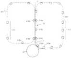
- FIG. 1shows a schematized side view of a folder according to a first embodiment of the present invention
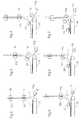
- FIG. 2shows a first printed product being tucked into a jaw element of the folder according to FIG. 1;
- FIGS. 3 and 4show the first printed product being carried toward a conveyor belt of the folder of FIG. 1;
- FIGS. 5, 6 and 7show the first printed product being fully cut and transported to the conveyor belt of the folder of FIG. 1;
- FIG. 8shows a folder according to a second embodiment of the present invention having a jaw cylinder after a signature formation area
- FIGS. 9 and 10show a signature being tucked in the jaw cylinder of the folder of FIG. 8, and
- FIG. 11shows a tucking element and a jaw element of the first embodiment.
- FIG. 1shows a folder 1 having a set 10 of movable elements, including movable elements 10 a , 10 b , 10 c , and a set 20 of movable elements, including movable elements 20 a , 20 b , 20 c .
- Set 10moves along a track 101 in a counterclockwise direction, while set 20 moves along a track 201 in a clockwise direction, so that sets 10 , 20 run next to each other in a signature formation area 2 .
- Set 10also includes tucking elements 10 d and 10 f , and gripping elements 10 e and 10 g .
- Set 20includes jaw elements 20 d and 20 f , and cutting elements 20 e and 20 g .
- the jaw elements 20 d and 20 finteract with tucking elements 10 d and f as will be described.
- the cutting elements 20 e , 20 ginteract with gripping elements 10 e , 10 g , respectively, in a manner similar to that described in co-pending U.S. patent application Ser. No. 09/452,975 incorporated by reference above. It is noted however, that other cutting and gripping mechanisms are possible, so long as the web is cut and the lead edge gripped by the cutting element/gripping element pair.
- a cutting elementmay include either a cutting anvil, in which case a gripper element includes a blade, or, preferably, a cutting blade.
- Set 10has alternating tucking and gripping elements and set 20 has alternating jaw and cutting elements.
- a web 3 of material such as paperenters a gap formed between set 10 and set 20 in the signature formation area 2 .
- Webas defined herein may include one or more ribbons of material, which may or may not already be longitudinally folded. Web 3 is cut into signatures in signature folding area 2 , the signatures being cross-folded and delivered to a conveyor 30 .
- web 3As web 3 enters the signature formation area, web 3 is held between cutting element 20 e , which may include bars and a knife, and cutting element 10 e , which may include a gripper and an anvil. Web 3 is thus gripped between the bars of cutting element 20 e and the anvil of gripping element 10 e as the cutting element 20 e and gripping element 10 e come together in signature formation area 2 .
- the cutting elements and gripping elementscan move at the same velocity as web 3 in the signature formation area 2 .
- a tucking blade 14(FIG. 11) of tucking element 10 f is activated to fold signature 7 in half by tucking the signature at its midpoint into jaw element 20 f .
- a schematic depiction of tucking element 10 f and jaw element 20 fis shown in FIG. 11 .
- Each jaw elementmay comprise a body 22 , wheels running on track 201 , and magnets 23 and 24 for interacting with windings in the track 201 .
- Magnets 23 , 24may be structured to accommodate any turns or curves in track 201 .
- Jaw element 20 fmay thus be driven using linear motor technology as described in co-pending U.S.
- Jaw element 20 fthus may be variably spaced with respect to cutting elements 20 e and 20 g , for example to be midway between these two elements.
- the disk drive described in the '975 applicationcould be used to position the tucking element within signature formation area 2 .
- All of the movable elements of the set 10 and set 20 , including jaw element 10 fcan be driven with one of these two technologies to provide variable spacing of the movable elements.
- Jaw element 20 falso includes a jaw 25 and may include a clamp 26 driven by a clamp actuator 27 .
- Tucking element 10 fincludes a body 12 , a tucking blade 14 and a tucking blade actuator 16 .
- Tucking element 10 fmay also include glide elements 17 , 18 which loosely position web 3 , which becomes a signature 7 , between body 12 and body 22 .
- signature 7can move with respect to glide elements 17 , 18 .
- Tucking blade 14may be actuated by tucking blade actuator 16 , which can be a gear.
- the actuatorcan be actuated by a variable cam mechanism or a motor, for example.
- the actuating motorcould be activated by RF or other wireless signals, for example.
- clamp 26may be activated by clamping actuator 27 , which may be controlled in a similar manner as blade actuator 16 , i.e. cam or motor driven.
- gripping element 10 gDuring the folding operation, lead edge of signature 7 is gripped by gripping element 10 g , and the trail edge is held between a bar of cutting element 20 e and an anvil of gripping element 10 e . Gripping element 10 g decelerates as the fold is created to permit the fold to develop, shown in FIG. 3 . As shown in FIGS. 4 and 5, jaw element 20 f then transports signature 7 to a conveyor belt 30 , with the lead edge of signature 7 being released by gripper element 10 g (FIG. 4) and the trail edge of signature 7 being released from between a bar of cutting element 20 e and the anvil of gripper element 10 e (which has since gripped the lead edge of web 3 ).
- FIGS. 6 and 7show signature 7 being decelerated and delivered to conveyor belt 30 , at which time clamp 26 may be released and the signature further conveyed by conveyor 30 .
- FIG. 8shows a second embodiment of the present invention, in which folder has two tracks 301 , 401 and a jaw cylinder 70 .
- a set 310 of variably spacable movable elementsruns around track 301 .
- Set 310includes gripping elements 310 a , 310 c and 310 e , as well as tucking elements 310 b , 310 d .
- a set 410 of variably spacable cutting elementsruns on track 401 , including cutting elements 410 a and 410 b.
- web 3As web 3 enters a signature formation area 72 , web 3 is held between cutting elements 410 b and gripping element 310 c , and is cut so as to form a trail edge of signature 7 and a lead edge of the next signature gripped by gripping element 310 c .
- the lead edge of signature 7is held by gripping element 310 e (and was formed by a cut from cutting element 410 c ).
- tucking element 310 dAs a midpoint of signature 7 reaches jaw cylinder 70 , tucking element 310 d is activated to fold signature 7 , which is then further transported by jaw cylinder 70 in a clockwise direction, as shown in FIGS. 9 and 10.
- the length of the signaturesmay be controlled by controlling the distance between consecutive pairs of cutting elements and gripping elements within the signature formation area.
- the present inventionprovides for a variable signature length.
- linear motor technologymay be used to drive the various movable elements.
- the tracksform the stator of the linear motor. These tracks have electrical windings.
- the spacing of the windings or the current within the windingscan vary to provide for acceleration and deceleration of the movable elements.
- design of the windings in the stator and controlling the frequency of the current applied to the windingsdefines and controls the motion and the spacing of the movable elements, which have magnets which are driven by the current in the electrical windings.
- Press speed signal and operator inputs of desired cut-to-cut lengthare linked to the linear motor's controller, for example through a PLC.
- precise position control of the clamping barsmay also require using linear encoder feedback.
- Cutting elementas defined herein need not include a gripper, but may merely function as an anvil or a blade for the respective cutting element.
- “Variably spacable” as defined hereinmeans that the movable elements may be moved in a controlled manner to set the distance between the elements.
Landscapes
- Engineering & Computer Science (AREA)
- Mechanical Engineering (AREA)
- Life Sciences & Earth Sciences (AREA)
- Forests & Forestry (AREA)
- Folding Of Thin Sheet-Like Materials, Special Discharging Devices, And Others (AREA)
Abstract
Description
Claims (16)
Priority Applications (2)
| Application Number | Priority Date | Filing Date | Title |
|---|---|---|---|
| US09/559,289US6537188B1 (en) | 2000-04-27 | 2000-04-27 | Variable-length cut-off jaw folder |
| DE10111648ADE10111648A1 (en) | 2000-04-27 | 2001-03-12 | Cutter and folder of signatures has two rows of movable elements, two cutters, grippers, folders with knife |
Applications Claiming Priority (1)
| Application Number | Priority Date | Filing Date | Title |
|---|---|---|---|
| US09/559,289US6537188B1 (en) | 2000-04-27 | 2000-04-27 | Variable-length cut-off jaw folder |
Publications (1)
| Publication Number | Publication Date |
|---|---|
| US6537188B1true US6537188B1 (en) | 2003-03-25 |
Family
ID=24233025
Family Applications (1)
| Application Number | Title | Priority Date | Filing Date |
|---|---|---|---|
| US09/559,289Expired - Fee RelatedUS6537188B1 (en) | 2000-04-27 | 2000-04-27 | Variable-length cut-off jaw folder |
Country Status (2)
| Country | Link |
|---|---|
| US (1) | US6537188B1 (en) |
| DE (1) | DE10111648A1 (en) |
Cited By (2)
| Publication number | Priority date | Publication date | Assignee | Title |
|---|---|---|---|---|
| US20030115997A1 (en)* | 1999-12-02 | 2003-06-26 | Michael William Hilliard | Variable-length cut-off folder and method |
| US6918586B1 (en)* | 1997-08-13 | 2005-07-19 | Goss International Americas Inc. | Method and apparatus for providing positive control of a printable medium in a printing system |
Citations (7)
| Publication number | Priority date | Publication date | Assignee | Title |
|---|---|---|---|---|
| US4893534A (en)* | 1987-06-30 | 1990-01-16 | Man Roland Druckmaschinen Ag | Combination web cutting and path switching system |
| US5004451A (en)* | 1989-02-11 | 1991-04-02 | Albert-Frankenthal Ag | Folding apparatus with improved web transport |
| US5443437A (en)* | 1991-11-08 | 1995-08-22 | Heidelberger Druckmaschinen | Device for automatically adjusting a fold in a folding apparatus of a rotary printing machine |
| US5571069A (en)* | 1993-06-03 | 1996-11-05 | Shah; Chandrakant K. | Paper folding assembly with a cutting cylinder lap adjustment apparatus and method |
| US5707330A (en)* | 1995-03-24 | 1998-01-13 | Goss Graphic Systems, Inc. | Folding machine for folding and cutting webs in a rotary printing press |
| US5865082A (en) | 1996-09-04 | 1999-02-02 | Heidelberg Harris Inc. | Apparatus for transporting signatures |
| US6159138A (en)* | 1998-01-27 | 2000-12-12 | Heidelberger Druckmaschinen Ag | Folder having a cylinder with retractable grippers and a cooperating cylinder with retractable copy guiding devices |
- 2000
- 2000-04-27USUS09/559,289patent/US6537188B1/ennot_activeExpired - Fee Related
- 2001
- 2001-03-12DEDE10111648Apatent/DE10111648A1/ennot_activeWithdrawn
Patent Citations (7)
| Publication number | Priority date | Publication date | Assignee | Title |
|---|---|---|---|---|
| US4893534A (en)* | 1987-06-30 | 1990-01-16 | Man Roland Druckmaschinen Ag | Combination web cutting and path switching system |
| US5004451A (en)* | 1989-02-11 | 1991-04-02 | Albert-Frankenthal Ag | Folding apparatus with improved web transport |
| US5443437A (en)* | 1991-11-08 | 1995-08-22 | Heidelberger Druckmaschinen | Device for automatically adjusting a fold in a folding apparatus of a rotary printing machine |
| US5571069A (en)* | 1993-06-03 | 1996-11-05 | Shah; Chandrakant K. | Paper folding assembly with a cutting cylinder lap adjustment apparatus and method |
| US5707330A (en)* | 1995-03-24 | 1998-01-13 | Goss Graphic Systems, Inc. | Folding machine for folding and cutting webs in a rotary printing press |
| US5865082A (en) | 1996-09-04 | 1999-02-02 | Heidelberg Harris Inc. | Apparatus for transporting signatures |
| US6159138A (en)* | 1998-01-27 | 2000-12-12 | Heidelberger Druckmaschinen Ag | Folder having a cylinder with retractable grippers and a cooperating cylinder with retractable copy guiding devices |
Non-Patent Citations (1)
| Title |
|---|
| U.S. Ser. No. 09/452,975, filed Dec. 2, 1999, assigned to Art Unit 3724. |
Cited By (3)
| Publication number | Priority date | Publication date | Assignee | Title |
|---|---|---|---|---|
| US6918586B1 (en)* | 1997-08-13 | 2005-07-19 | Goss International Americas Inc. | Method and apparatus for providing positive control of a printable medium in a printing system |
| US20030115997A1 (en)* | 1999-12-02 | 2003-06-26 | Michael William Hilliard | Variable-length cut-off folder and method |
| US6684746B2 (en)* | 1999-12-02 | 2004-02-03 | Heidelberger Druckmaschinen Ag | Variable-length cut-off folder and method |
Also Published As
| Publication number | Publication date |
|---|---|
| DE10111648A1 (en) | 2001-10-31 |
Similar Documents
| Publication | Publication Date | Title |
|---|---|---|
| US6572097B2 (en) | Apparatus for slowing down and guiding a signature and method for doing the same | |
| US5405126A (en) | Format-variable combination folder | |
| JP2566551B2 (en) | Paper folding device for folding a book in a web-fed rotary printing press | |
| EP0907515B1 (en) | Sheet conveyer for a rotary press | |
| US8104755B2 (en) | Adjustable delivery web conversion apparatus and method | |
| JP2019098514A (en) | Apparatus and method for cutting or perforating paper web | |
| US5439206A (en) | Product delivery system for a printing-press folder | |
| US20140342893A1 (en) | Variable Folding System Comprising Linear Drives, Especially For Printing Machines | |
| JPH05178532A (en) | Folding device | |
| JP2000302310A (en) | Route converter for continuous series of flat product | |
| US4969862A (en) | Method and apparatus for producing folded articles | |
| JPS62275974A (en) | Folding machine with second or third folding section | |
| CN110203751B (en) | Device and method for further processing printed sheets printed in sequence | |
| US6684746B2 (en) | Variable-length cut-off folder and method | |
| US6941862B2 (en) | Folder | |
| US4491310A (en) | Adjustable folding apparatus | |
| US8020847B2 (en) | Multiple delivery web conversion apparatus and method of producing and delivering variable printed products | |
| US4190243A (en) | Folder assembly for book folding | |
| US6537188B1 (en) | Variable-length cut-off jaw folder | |
| US9469042B2 (en) | Method and apparatus for processing a material web | |
| US6652437B1 (en) | Actuated product seizing element in a folder apparatus | |
| JPH08295460A (en) | Folding machine which manufactures section by selectively performing one or two times of lateral foldings | |
| JPS60244758A (en) | Folding device | |
| US20090038454A1 (en) | Printing press folder with parallel process transport tapes | |
| JP2000007215A (en) | Device and method for carrying and decelerating folded sample |
Legal Events
| Date | Code | Title | Description |
|---|---|---|---|
| AS | Assignment | Owner name:HEIDELBERGER DRUCKMASCHINEN AG, GERMANY Free format text:ASSIGNMENT OF ASSIGNORS INTEREST;ASSIGNORS:COTE, KEVIN LAUREN;POLLOCK, DAVID CLARKE;REEL/FRAME:010967/0936;SIGNING DATES FROM 20000612 TO 20000613 | |
| CC | Certificate of correction | ||
| AS | Assignment | Owner name:U.S. BANK, N.A., MINNESOTA Free format text:SECURITY AGREEMENT;ASSIGNOR:HEIDELBERG WEB SYSTEMS, INC., A DELAWARE CORPORATION;REEL/FRAME:015722/0435 Effective date:20040806 | |
| AS | Assignment | Owner name:HEIDELBERG WEB SYSTEMS, INC., NEW HAMPSHIRE Free format text:ASSIGNMENT OF ASSIGNORS INTEREST;ASSIGNOR:HEIDELBERGER DRUCKMASCHINEN AG;REEL/FRAME:015886/0211 Effective date:20040806 | |
| AS | Assignment | Owner name:GOSS INTERNATIONAL AMERICAS, INC., NEW HAMPSHIRE Free format text:CHANGE OF NAME;ASSIGNOR:HEIDELBERG WEB SYSTEMS, INC.;REEL/FRAME:015886/0713 Effective date:20040809 | |
| FPAY | Fee payment | Year of fee payment:4 | |
| AS | Assignment | Owner name:U.S. BANK NATIONAL ASSOCIATION, AS COLLATERAL AGEN Free format text:SECURITY AGREEMENT;ASSIGNOR:GOSS INTERNATIONAL AMERICAS, INC.;REEL/FRAME:022960/0316 Effective date:20090710 | |
| AS | Assignment | Owner name:GOSS INTERNATIONAL AMERICAS, INC., ILLINOIS Free format text:RELEASE OF SECURITY INTEREST (GRANTED IN REEL 022960; FRAME 0316);ASSIGNOR:U.S. BANK, N.A., NATIONAL ASSOCIATION;REEL/FRAME:025012/0889 Effective date:20100914 | |
| FPAY | Fee payment | Year of fee payment:8 | |
| REMI | Maintenance fee reminder mailed | ||
| LAPS | Lapse for failure to pay maintenance fees | ||
| STCH | Information on status: patent discontinuation | Free format text:PATENT EXPIRED DUE TO NONPAYMENT OF MAINTENANCE FEES UNDER 37 CFR 1.362 | |
| FP | Lapsed due to failure to pay maintenance fee | Effective date:20150325 | |
| AS | Assignment | Owner name:SHANGHAI ELECTRIC (GROUP) CORPORATION, CHINA Free format text:ASSIGNMENT OF ASSIGNORS INTEREST;ASSIGNOR:GOSS INTERNATIONAL CORPORATION;REEL/FRAME:048304/0460 Effective date:20101231 |