US6536510B2 - Thermal bus for cabinets housing high power electronics equipment - Google Patents
Thermal bus for cabinets housing high power electronics equipmentDownload PDFInfo
- Publication number
- US6536510B2 US6536510B2US09/902,088US90208801AUS6536510B2US 6536510 B2US6536510 B2US 6536510B2US 90208801 AUS90208801 AUS 90208801AUS 6536510 B2US6536510 B2US 6536510B2
- Authority
- US
- United States
- Prior art keywords
- working fluid
- evaporators
- liquid
- condenser
- disposed
- Prior art date
- Legal status (The legal status is an assumption and is not a legal conclusion. Google has not performed a legal analysis and makes no representation as to the accuracy of the status listed.)
- Expired - Lifetime, expires
Links
Images


Classifications
- H—ELECTRICITY
- H05—ELECTRIC TECHNIQUES NOT OTHERWISE PROVIDED FOR
- H05K—PRINTED CIRCUITS; CASINGS OR CONSTRUCTIONAL DETAILS OF ELECTRIC APPARATUS; MANUFACTURE OF ASSEMBLAGES OF ELECTRICAL COMPONENTS
- H05K7/00—Constructional details common to different types of electric apparatus
- H05K7/20—Modifications to facilitate cooling, ventilating, or heating
- H05K7/20536—Modifications to facilitate cooling, ventilating, or heating for racks or cabinets of standardised dimensions, e.g. electronic racks for aircraft or telecommunication equipment
- H05K7/20663—Liquid coolant with phase change, e.g. heat pipes
- H05K7/20681—Liquid coolant with phase change, e.g. heat pipes within cabinets for removing heat from sub-racks
- F—MECHANICAL ENGINEERING; LIGHTING; HEATING; WEAPONS; BLASTING
- F28—HEAT EXCHANGE IN GENERAL
- F28D—HEAT-EXCHANGE APPARATUS, NOT PROVIDED FOR IN ANOTHER SUBCLASS, IN WHICH THE HEAT-EXCHANGE MEDIA DO NOT COME INTO DIRECT CONTACT
- F28D15/00—Heat-exchange apparatus with the intermediate heat-transfer medium in closed tubes passing into or through the conduit walls ; Heat-exchange apparatus employing intermediate heat-transfer medium or bodies
- F28D15/02—Heat-exchange apparatus with the intermediate heat-transfer medium in closed tubes passing into or through the conduit walls ; Heat-exchange apparatus employing intermediate heat-transfer medium or bodies in which the medium condenses and evaporates, e.g. heat pipes
- F28D15/0266—Heat-exchange apparatus with the intermediate heat-transfer medium in closed tubes passing into or through the conduit walls ; Heat-exchange apparatus employing intermediate heat-transfer medium or bodies in which the medium condenses and evaporates, e.g. heat pipes with separate evaporating and condensing chambers connected by at least one conduit; Loop-type heat pipes; with multiple or common evaporating or condensing chambers
Definitions
- the present inventiongenerally relates to heat management systems for high power electronics equipment, and more particularly to a thermal bus system for a cabinet housing high power, high thermal profile electronic components and systems.
- a typical prior art approach to cooling electronic componentsis to direct a stream of cooling air across the modules and/or cards carrying such devices.
- Several disadvantages to this approachhave been identified, including: high pressure drop; uniformity of component form factors; placing the components containing the integrated circuits further apart on the circuit cards; increasing the distance between circuit cards; and increasing the volume and velocity of cooling air directed over the components.
- This required increase in volume and velocity of cooling airrequires special considerations in the design of the housings containing the circuit cards and in the mechanical systems for delivering the cooling air.
- the air quality(moisture content, contamination, etc.)must be tightly controlled to inhibit corrosion, loss of cooling effectiveness, etc.
- cooling of components by this meansnecessitates a number of compromises to the overall system that prevent its use in many systems.
- one techniqueincludes the use of solid metal thermal mounting cards or plates which conduct the heat dissipated by electronic components to a heat sink (cold plate) disposed at the edge of each card.
- a heat sinkcold plate
- Such an approachresults in a large thermal resistance from the component mounting surface to the heat sink, which causes high component temperatures.
- a two-phase loop thermosyphonis used to bus thermal energy away from the electronic components. More particularly, two-phase loop thermosyphons are devices that use gravity to maintain two-phase fluid circulation during operation. Each loop thermosyphon has an evaporator, where vaporization occurs when it is heated, a vapor tube (or line) where the vapor flows to a condenser, a cooled condenser, where condensation takes place, and a liquid return line (transport lines). Sometimes a capillary structure is used in the evaporator to reduce its thermal resistance.
- thermosyphon evaporatorsmust have a vertical orientation so that the entire evaporator and capillary structure are flooded with liquid, which in turn boils when the evaporator is heated. This means that there is a liquid pool in the evaporator, and it is the boiling of that pool that is the main heat transfer mechanism in thermosyphon evaporators.
- pool boiling heat transferhas been found to be less effective than vaporization from the surface of a porous structure, in terms of the thermal resistance.
- U.S. Pat. No. 4,323,914issued to Berndlmaier et al. discloses the removal of heat from a Large Scale Integrated Circuit semiconductor package via a thermal conductive path including a thermally conductive liquid.
- the integrated circuit chipsare flip chips bonded to a substrate having a printed circuit and raised contact pads serving to interconnect contact areas on the chip.
- a metal or ceramic coverengages the perimeter of the substrate and encloses the chips (or chip).
- the thermal liquidis contained within the cavity defined by the cover and substrate.
- the chips (or chip) and the flip chip connectionsare protected from contamination and the deleterious effects of the thermally conductive liquid by a parylene film enveloping them.
- U.S. Pat. No. 4,366,526, issued to Lijol et al.discloses a circuit card for high-density packaging of electronic components for use in high power-density card racks in computer and other electronic and avionic systems.
- the cardhas an all metal construction with an elongated planar body portion for the mounting of electronic components on opposite sides, and has a heat pipe located along the edges of one elongated side and two ends.
- a connector for making the required electrical connections to the electronic componentsis provided along the edge of elongated side. Edge tabs on the ends of the card permit the card to be installed into a card rack in electronic equipment.
- the elongated portion of the heat pipeserves as the evaporator region and the two end portions act as the condensing regions.
- U.S. Pat. No. 4,931,905issued to Cirrito et al., discloses two metal plates that have U-shaped grooves so that the plates may form congruent halves wherein matching grooves complete independent heat pipes.
- a bight section of each heat pipeserves as an evaporator section while the parallel arms of each heat pipe form condenser sections.
- a wickis positioned within each heat pipe to improve liquid transport when a module is in a non-upright position.
- the condenser sectionsare located coincident with the normally upright edges of each module so that, when the module is upright, the vertically disposed condenser sections of the heat pipe gravity-assist liquid transport to the evaporator section.
- U.S. Pat. No. 5,283,715issued to Carlsten et al., discloses a heat pipe structure that is incorporated directly into the metal baseplate of a circuit card thereby eliminating thermal contact resistance between the baseplate and the heat pipe assembly.
- Componentsare mounted on a copper circuit layer bonded to a dielectric layer in a first portion of the baseplate with a second portion of the baseplate/heat pipe assembly extending into a heat sink/cold plate condensing area for removal of heat generated in the component portion.
- U.S. Pat. No. 6,055,157discloses a computer module for scalably adding computing power and cooling capacity to a computer system.
- the computing moduleincludes a first heat pipe assembly having an evaporator plate with an evaporator surface.
- the first heat pipealso has a condenser in fluid communication with the evaporator plate.
- the evaporator plateis positioned adjacent one side of a printed circuit board populated with at least one electronic component, or a printed circuit board which has two sides populated with electronic components.
- a second heat pipe having the same constructionis positioned adjacent the other side of the printed circuit board so that the electronic components on the other side are positioned adjacent the evaporator surface of the second heat pipe.
- the evaporator plate of each heat pipeis connected to the condenser by a plurality of necked-down regions. This forms at least one window between the condenser and the evaporator plate of each heat pipe.
- the windows of the various heat pipesalign. Electrical connector components can be routed through the windows. The connector component connects the edge of the printed circuit board positioned near the windows.
- the present inventionprovides a thermal bus for cabinets housing high power electronics equipment.
- two spaced-apart substantially horizontally oriented evaporatorsare provided where each is substantially horizontally mounted in a support and positioned in thermal communication with at least one heat generating device.
- Each of the two elongate evaporatorsdefines a central passageway having a liquid-working fluid entrance port and a vaporous-working fluid exit port and a capillary wick disposed on the walls of the central passageway.
- a duct defining a central passageway and having a capillary wick disposed on the walls of the central passagewayis disposed in fluid communication with the central passageways of the two spaced-apart evaporators
- a condenseris provided having a vaporous-working fluid entrance port disposed in flow communication with the vaporous-working fluid exit port and a liquid-working fluid exit port disposed in flow communication with the liquid-working fluid entrance port so that a working fluid cycles through the two spaced-apart evaporators, and between the condenser and the two spaced-apart evaporators.
- a thermal busfor cabinets housing high power electronics equipment that includes two substantially horizontally oriented parallel evaporators interconnected in flow communication with a condenser.
- Each evaporatoris substantially horizontally mounted in a support having a central recess and each having a tube having a capillary wick disposed on an internal surface and being mounted within the central recess of the support.
- Each of the tubesincludes a closed distal end and a closed proximal end with a liquid-working fluid entrance port located at the closed proximal end of the first tube and a vaporous-working fluid exit port located at the closed proximal end of the second tube.
- a duct defining a central passageway and having a capillary wick disposed on the walls of the central passagewayis disposed in fluid communication with the first tube and the second tube.
- the condenserhas a vaporous-working fluid entrance port disposed in flow communication with the vaporous-working fluid exit port of the evaporator and a liquid-working fluid exit port disposed in flow communication with the liquid-working fluid entrance port of the evaporator so that a working fluid cycles; (i) through the two spaced-apart parallel evaporators, and (ii) between the condenser and the two tubes.
- a system for controlling the heat generated within a cabinet housing high power electronics equipmentcomprising, in combination, a plurality of circuit boards having heat generating devices disposed on at least one surface and a plurality of substantially horizontally oriented thermal buses.
- Each thermal buscomprises two spaced-apart evaporators that are each substantially horizontally mounted in a support and positioned in thermal communication with at least one of the plurality of circuit boards.
- Each of the two elongate evaporatorsdefines a central passageway having a liquid-working fluid entrance port and a vaporous-working fluid exit port and a capillary wick disposed on the walls of the central passageway.
- a duct defining a central passageway and having a capillary wick disposed on the walls of the central passagewayis disposed in fluid communication with the central passageways of the two spaced-apart evaporators.
- a condenseris provided having a vaporous-working fluid entrance port disposed in flow communication with the vaporous-working fluid exit port and a liquid-working fluid exit port disposed in flow communication with the liquid-working fluid entrance port so that a working fluid cycles; (i) through the two spaced-apart evaporators, and (ii) between the condenser and the two spaced-apart evaporators.
- a rackis positioned within the cabinet so as to support the plurality of thermal busses and circuit boards in a substantially horizontal relation to the rack.
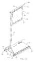
- FIG. 1is a perspective view of a cabinet for housing high power electronics equipment, including a plurality of thermal buses formed in accordance with the present invention
- FIG. 2is a perspective view of the plurality of thermal buses shown in FIG. 1, with the cabinet removed for clarity of illustration;
- FIG. 3is a perspective view of an individual thermal bus having a circuit board positioned on a pair of rail-evaporators;
- FIG. 4is a is a perspective of the thermal bus shown in FIG. 3, with the circuit board suspended above the rail-evaporator for clarity of illustration;
- FIG. 5is a cross-sectional view of a proximal portion of a rail-evaporator, as taken along lines 5 — 5 in FIG. 4;
- FIG. 6is a cross-sectional view of a central portion of an rail-evaporator, as taken along lines 6 — 6 in FIG. 4;
- FIG. 7is a cross-sectional view of the distal portion of the rail evaporator and an inter-rail duct, as taken along lines 7 — 7 in FIG. 4;
- FIG. 8is a cross-sectional view of a condenser formed in accordance with the present invention, as taken along line 8 — 8 in FIG. 4;
- FIG. 9is a cross-sectional view of an end cap assembly used in connection with the condenser, as viewed along line 9 — 9 in FIG. 4;
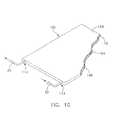
- FIG. 10is a partially broken-away, perspective view of another alternative embodiment of evaporator for use in connection with the present invention.
- FIG. 11is a cross-sectional side view of an alternative condenser formed in accordance with the present invention.
- FIG. 12is a perspective view of one embodiment of evaporator comprising a vapor chamber and working-fluid transport tube;
- FIG. 13is a cross-sectional view, as taken along line 13 — 13 , of the evaporator shown in FIG. 12;
- FIG. 14is a cross-sectional view of an alternative arrangement of a working-fluid transport tube mounted to an evaporator;
- FIG. 15is a cross-sectional view of another alternative arrangement of a working-fluid transport tube mounted to an evaporator;
- FIG. 16is a side elevational view of an alternative evaporator formed in accordance with the present invention.
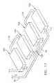
- FIG. 17is a perspective view of another embodiment of the invention comprising a plurality of vapor chamber type evaporators arranged in serial flow communication;
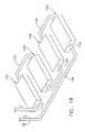
- FIG. 18is a perspective view of yet another embodiment of the invention comprising a plurality of cold plate type evaporators arranged in serial flow communication;
- FIG. 19is a perspective view of yet another embodiment of the invention comprising a plurality of vapor chamber type evaporators arranged in parallel flow communication.
- the present inventionprovides a plurality of passive, two phase thermal buses 5 that are integrated within an electronics cabinet 10 .
- Each thermal bus 5operates to collect thermal energy from individual electronic components 7 , or from circuit boards 9 (FIG. 3) that support a plurality of such electronic components 7 , and to transport the collected thermal energy to an external sink 12 .
- Electronics cabinet 10comprises a generally rectilinear hollow structure having a top wall 17 that is vertically spaced from a bottom wall 18 , and side walls 19 that are joined along coextensive edges, with surfaces that are horizontally spaced from one another.
- Electronics cabinet 10also includes an access panel 21 and a rack 23 positioned within the enclosure formed by top wall 17 , side walls 19 , and access panel 21 .
- one embodiment of the inventionprovides a thermal bus 5 that may be used to transport the heat generated by components that are arranged in discrete rows on a horizontally oriented circuit board 9 .
- the arrangement of electronic components in discrete rows on a circuit boardis quite common in applications which use, for example, a small number of high power amplifiers. The heat flux in such applications can often exceed 25 watts/cm 2 .
- each circuit board 9 in electronics cabinet 10is fastened to a thermal bus 5 comprising a pair of substantially horizontally oriented rail-evaporators 30 , an inter-rail duct 31 , a vapor conduit 32 , a liquid conduit 34 , and a plate condenser 36 .
- electronics cabinet 10may include a plurality of pairs of horizontally oriented rail-evaporators 30 so as to manage the thermal energy generation from a plurality of horizontally oriented circuit boards 9 that are stacked one-above-another on rack 23 (FIG. 1 ).
- circuit boards 9When supported by rail-evaporators 30 , circuit boards 9 extend transversely between sidewalls 19 .
- Rail-evaporators 30may be tilted relative to a horizontal plane passing through sidewalls 19 , by as much as ten degrees or so.
- rail evaporators 30are arranged in spaced apart, substantially parallel relation to one another, with each rail evaporator 30 including a rail 40 having a milled channel 42 (FIGS. 5 and 6) that extends along its length, and a rectilinear tube 44 mounted within channel 42 .
- Rail evaporators 30may be formed from any of the well known metals utilized for heat transfer applications, e.g., copper or its alloys, aluminum or its alloys, steels, etc.
- Each channel 42is open ended, and includes an inner opening 43 that is sized to receive inter-rail duct 31 (FIG. 7 ).
- Inter-rail duct 31preferably comprises a hollow cylindrical cross-section tube 45 having open ends and an interior surface 47 that forms a central passageway 48 .
- Each tube 44comprises a closed distal end 46 , a side bore 49 , a closed proximal end 51 , a port 53 , 54 located on a top portion of proximal end 51 , and an exposed thermal interface surface 55 (FIG. 4 ).
- Each side bore 49is located adjacent to closed distal end 46 , and is arranged in aligned relation with opening 43 of channel 42 . Bores 49 and openings 43 are sized and shaped to sealingly receive a respective open end of inter-rail duct 31 .
- Each tube 44preferably comprises a rectilinear cross-section, which when mounted within channel 42 , provides for more surface area for heat exchange and conductive contact between thermal interface surface 55 and the bottom surface of circuit board 9 .
- Tubes 44are preferably formed from a soft, highly thermally conductive metal, such as, copper or aluminum.
- An interior surface 60 of each tube 44defines a central passageway 62 and supports a capillary wick 64 .
- Capillary wick 64extends throughout interior surface 60 of both tubes 44 , ports 53 , 54 , and the interior surface of inter-rail duct 31 .
- Capillary wick 64may comprise adjacent layers of screening or a sintered powder structure with interstices between the particles of powder.
- wick 64may comprise sintered copper powder, aluminum-silicon-carbide (AlSiC) or copper-silicon-carbide (CuSiC) having an average thickness of about 0.1 mm to 1.0 mm.
- a working fluid(not shown) is introduced into tube 44 so as to form a heat pipe that comprises both tubes 44 and inter-rail-duct 31 for each thermal bus 5 .
- the working fluidmay comprise any of the well known two-phase vaporizable liquids, e.g., water, alcohol, freon, etc.
- the working fluidflows along each horizontally arranged (or tilted) rail-evaporator 30 mainly due to the frictional vapor-liquid interaction on the liquid free surface of central passageway 62 . Vaporization of the working fluid occurs mainly in the porous structure of wick 64 , which is not typically flooded with working fluid during operation. This ensures very low thermal resistance of rail-evaporators 30 compared to a conventional, vertically oriented, thermosyphon evaporator.
- vapor conduit 32 and liquid conduit 34comprise open-ended tubes that extend along an outer portion of rack 23 between each pair of rail-evaporators 30 and an individual condenser 36 .
- One open end of vapor conduit 32is mounted in flow communication with port 53 located on the top portion of proximal end 51 of one rail-evaporator 30 .
- the other open end of vapor conduit 32is mounted in flow communication with a first manifold that is interconnected with a top portion of plate condenser 36 .
- One open end of liquid conduit 34is mounted in flow communication with port 54 located on the top portion of proximal end 51 of the other rail-evaporator 30 in the pair.
- liquid conduit 34is mounted in flow communication with a second manifold that is interconnected with a bottom portion of plate condenser 36 .
- Vapor conduit 32 and liquid conduit 34are preferably formed from metal tubing, with vapor conduit 32 preferably having a relatively larger diameter than liquid conduit 34 .
- plate condenser 36is formed from a conduct metal, such as copper, aluminum, or steel and comprises a front wall 70 , a rear wall 72 , a plurality of inlets ducts 74 extending from an inlet manifold 75 , a plurality of outlet ducts 76 extending into an outlet manifold 77 , and an end cap assembly 80 .
- Each condenser 36is associated with a single pair of rail-evaporators 30 .
- Front wall 70 and rear wall 72include confronting surfaces that may include a variety of surface features (e.g., posts, mesh, grooves, irregularly shaped protrusions, baffles, and wick materials) that are adapted for aiding in the dispersal of thermal energy from the working fluid to front wall 70 and rear wall 72 as it passes between them.
- surface featurese.g., posts, mesh, grooves, irregularly shaped protrusions, baffles, and wick materials
- cross-tubes 82extend from inlet ducts 74 , between front plate 70 and rear plate 72 , and into outlet 76 .
- a serpentine shaped conduit 83is positioned between front wall 70 and rear wall 72 (FIG. 11 ).
- Condenser 36acts as a heat exchanger transferring heat contained in a mixture of vaporous working fluid and liquid working fluid (not shown) to the ambient surroundings, via external heat sink 12 .
- External heat sink 12may comprise conventional heat exchangers having the capability to facilitate transfer of thermal it energy, and are often heat transfer devices, such as a fin stack, cold plate or secondary heat exchanger of the type well known in the art.
- condensers 36are thermally engaged with a conventional fin stack and cold plate that are adapted to utilize air flow for the transfer of heat.
- end cap assembly 80comprises a condenser end cap 84 , a fill tube 86 , and a fill tube protector 88 .
- condenser end cap 84comprises a resilient material that is adapted to sealingly fill the end of an inner passageway of inlet manifold 75 .
- Fill tube 86extends through condenser end cap 84 and provides for flow communication with the inner portions of inlet manifold 75 .
- Fill tube protector 88is positioned in surrounding relation to condenser end cap 84 and fill tube 86 , and includes an entrance opening 90 that is arranged adjacent to and open end of fill tube 86 . In this way, thermal bus 5 may be partially evacuated, and then filled with the working fluid prior to sealing opening 90 in end cap protector 88 .
- Each thermal bus 5operates in the following manner. As thermal energy is generated by components 7 on circuit boards 9 , the working fluid disposed within horizontally oriented tubes 44 evaporates and moves toward port 53 and the entrance to vapor conduit 32 . It should be understood that tubes 44 and inter-rail duct 31 function as a heat pipe to the extent that liquid is wicked by capillary wick 64 from cooler portions of tubes 44 to higher temperature portions, and therefore are unaffected by their horizontal orientation. Liquid is also moved by capillary action between tubes 44 as a result of capillary wick 64 being present within internal passageway 48 of inter-rail duct 31 .
- Vapor conduit 32has a relatively large diameter to accommodate vaporized working fluid at various vapor pressures.
- the vaporized working fluidmoves through vapor conduit 32 and into inlet manifold 75 positioned above condenser 36 . Once the vaporized working fluid enters inlet manifold 75 it travels through inlet ducts 74 into the interior of condenser 36 where the vaporized working fluid condenses on the relatively cooler interior surfaces of front and rear walls 70 and 72 .
- Condensed working fluidmoves toward a bottom portion of condenser 36 , via cross-tubes 82 , and enters outlet manifold 77 via outlet ducts 76 .
- Liquid conduit 34is arranged in flow communication with the interior of outlet manifold 77 such that condensed, liquid working fluid enters liquid conduit 34 and travels, by force of gravity, back to port 54 so as to be reintroduced into tubes 44 of rail-evaporators 30 .
- two alternative embodiments of the present inventioncomprise the use of either a vapor chamber evaporator 100 or cold plate 105 in place of rail evaporators 30 .
- vapor chamber evaporator 100comprises a top plate 106 , a bottom plate 108 , and internal chamber 110 having interior surfaces covered by capillary wick 64 .
- Vapor chamber evaporator 100operates as a heat pipe, inasmuch as internal chamber 110 is partially evacuated and filled with a working fluid.
- An entrance port 112 and exit port 114interconnect liquid conduit 34 and vapor conduit 32 with the ends of a serpentine conduit 118 that is embedded within vapor chamber evaporator 100 (FIGS. 10 and 12 - 15 ).
- This embodiment of the inventionoperates in the same manner as previously described.
- a cold plate 105may be substituted for vapor chamber evaporator 100 (FIG. 16 ).
- Cold plate 105is formed from a flat sheet of thermally conductive material, such as copper, aluminum, steel, or the like.
- Each cold plate 105includes a channel 120 .
- Channel 120may have a rectilinear cross-section, but other cross-sectional shapes, i.e., oval, round, polygonal may also be used with good effect, with each cutting path through surface 128 of cold plate 105 .
- various other shapes and arrangementsmay be employed, e.g., zig-zag, stepped, spiral, etc., depending upon the pattern of components 7 on circuit board 9 .
- a conduit 122is positioned within channel 120 , and is interconnected in flow communication with vapor conduit 32 and liquid conduit 34 . This embodiment of the invention operates in a similar manner as previously described.
- the horizontal evaporators of the present inventionmay be formed from several individual vapor chamber evaporators 100 or cold plates 105 as required to solve a particular design need. As shown in FIGS. 17-19, a plurality of substantially horizontally oriented evaporators 100 or 105 may be arranged in serial flow communication to one another or in parallel flow communication to one another by means of interconnecting conduits 125 . In some instances a hydraulic resistance 130 (e.g., porous slugs or orifices inside the liquid return lines) may be inserted in liquid conduit 125 in order to regulate liquid flow into vapor chamber evaporators 100 or cold plates 105 by more evenly returning liquid working fluid between the parallel vapor chambers. Hydraulic resistances 130 may be tuned for the varying heat load on different vapor chambers.
- a hydraulic resistance 130e.g., porous slugs or orifices inside the liquid return lines
Landscapes
- Engineering & Computer Science (AREA)
- Physics & Mathematics (AREA)
- Thermal Sciences (AREA)
- Life Sciences & Earth Sciences (AREA)
- Sustainable Development (AREA)
- Mechanical Engineering (AREA)
- General Engineering & Computer Science (AREA)
- Aviation & Aerospace Engineering (AREA)
- Microelectronics & Electronic Packaging (AREA)
- Cooling Or The Like Of Semiconductors Or Solid State Devices (AREA)
Abstract
Description
Claims (36)
Priority Applications (3)
| Application Number | Priority Date | Filing Date | Title |
|---|---|---|---|
| US09/902,088US6536510B2 (en) | 2001-07-10 | 2001-07-10 | Thermal bus for cabinets housing high power electronics equipment |
| EP02752205AEP1415122A1 (en) | 2001-07-10 | 2002-07-09 | Thermal bus for cabinets housing high power electronics equipment |
| PCT/US2002/021511WO2003006910A1 (en) | 2001-07-10 | 2002-07-09 | Thermal bus for cabinets housing high power electronics equipment |
Applications Claiming Priority (1)
| Application Number | Priority Date | Filing Date | Title |
|---|---|---|---|
| US09/902,088US6536510B2 (en) | 2001-07-10 | 2001-07-10 | Thermal bus for cabinets housing high power electronics equipment |
Publications (2)
| Publication Number | Publication Date |
|---|---|
| US20030010477A1 US20030010477A1 (en) | 2003-01-16 |
| US6536510B2true US6536510B2 (en) | 2003-03-25 |
Family
ID=25415284
Family Applications (1)
| Application Number | Title | Priority Date | Filing Date |
|---|---|---|---|
| US09/902,088Expired - LifetimeUS6536510B2 (en) | 2001-07-10 | 2001-07-10 | Thermal bus for cabinets housing high power electronics equipment |
Country Status (3)
| Country | Link |
|---|---|
| US (1) | US6536510B2 (en) |
| EP (1) | EP1415122A1 (en) |
| WO (1) | WO2003006910A1 (en) |
Cited By (94)
| Publication number | Priority date | Publication date | Assignee | Title |
|---|---|---|---|---|
| US20030051859A1 (en)* | 2001-09-20 | 2003-03-20 | Chesser Jason B. | Modular capillary pumped loop cooling system |
| US20030098588A1 (en)* | 2001-11-26 | 2003-05-29 | Kazuaki Yazawa | Method and apparatus for converting dissipated heat to work energy |
| US20030230399A1 (en)* | 2002-06-14 | 2003-12-18 | Hurlbert Kathryn M. | Apparatus and method for extracting heat from a device |
| US20040037045A1 (en)* | 2002-08-14 | 2004-02-26 | Phillips Alfred L. | Thermal bus for electronics systems |
| US20040069455A1 (en)* | 2002-08-28 | 2004-04-15 | Lindemuth James E. | Vapor chamber with sintered grooved wick |
| US20040112571A1 (en)* | 2002-11-01 | 2004-06-17 | Cooligy, Inc. | Method and apparatus for efficient vertical fluid delivery for cooling a heat producing device |
| US20040182551A1 (en)* | 2003-03-17 | 2004-09-23 | Cooligy, Inc. | Boiling temperature design in pumped microchannel cooling loops |
| US20040190253A1 (en)* | 2003-03-31 | 2004-09-30 | Ravi Prasher | Channeled heat sink and chassis with integrated heat rejector for two-phase cooling |
| US20040211549A1 (en)* | 2003-04-24 | 2004-10-28 | Garner Scott D. | Sintered grooved wick with particle web |
| US20040234378A1 (en)* | 2003-01-31 | 2004-11-25 | James Lovette | Method and apparatus for low-cost electrokinetic pump manufacturing |
| US20040233639A1 (en)* | 2003-01-31 | 2004-11-25 | Cooligy, Inc. | Removeable heat spreader support mechanism and method of manufacturing thereof |
| US20050011633A1 (en)* | 2003-07-14 | 2005-01-20 | Garner Scott D. | Tower heat sink with sintered grooved wick |
| US20050024831A1 (en)* | 2003-07-28 | 2005-02-03 | Phillips Alfred L. | Flexible loop thermosyphon |
| US20050067147A1 (en)* | 2003-09-02 | 2005-03-31 | Thayer John Gilbert | Loop thermosyphon for cooling semiconductors during burn-in testing |
| US20050068728A1 (en)* | 2003-09-30 | 2005-03-31 | International Business Machines Corporation | Thermal dissipation assembly and fabrication method for electronics drawer of a multiple-drawer electronics rack |
| US20050117297A1 (en)* | 2002-03-11 | 2005-06-02 | Michael Nicolai | Cooling array |
| US20050138440A1 (en)* | 2003-12-18 | 2005-06-23 | Barr Andrew H. | Equipment rack load modulation system and method |
| US20050150242A1 (en)* | 2002-03-15 | 2005-07-14 | Siemens Aktiengesellschaft | Refrigeration plant for parts of installation, which are to be chilled |
| US20050168948A1 (en)* | 2004-01-30 | 2005-08-04 | Isothermal Systems Research | Low momentum loss fluid manifold system |
| US20050211418A1 (en)* | 2002-11-01 | 2005-09-29 | Cooligy, Inc. | Method and apparatus for efficient vertical fluid delivery for cooling a heat producing device |
| US20050211417A1 (en)* | 2002-11-01 | 2005-09-29 | Cooligy,Inc. | Interwoven manifolds for pressure drop reduction in microchannel heat exchangers |
| US20050211427A1 (en)* | 2002-11-01 | 2005-09-29 | Cooligy, Inc. | Method and apparatus for flexible fluid delivery for cooling desired hot spots in a heat producing device |
| US20050269691A1 (en)* | 2004-06-04 | 2005-12-08 | Cooligy, Inc. | Counter flow micro heat exchanger for optimal performance |
| US20050274487A1 (en)* | 2004-05-27 | 2005-12-15 | International Business Machines Corporation | Method and apparatus for reducing thermal resistance in a vertical heat sink assembly |
| US20060002086A1 (en)* | 2004-06-30 | 2006-01-05 | Teneketges Nicholas J | Heat exchange apparatus with parallel flow |
| US20060067047A1 (en)* | 2004-09-30 | 2006-03-30 | Pfahnl Andreas C | Modular liquid cooling of electronic assemblies |
| US20060082970A1 (en)* | 2004-10-19 | 2006-04-20 | Walz Andrew A | Electrical module and support therefor with integrated cooling |
| US20060090494A1 (en)* | 2004-11-01 | 2006-05-04 | Manole Dan M | Compact refrigeration system for providing multiple levels of cooling |
| US20060109633A1 (en)* | 2004-11-09 | 2006-05-25 | Werner Sonnabend | Cooling arrangement |
| US20060120036A1 (en)* | 2004-12-07 | 2006-06-08 | Uwe Rockenfeller | Thermal bus load control management for electronic systems |
| US20060180300A1 (en)* | 2003-07-23 | 2006-08-17 | Lenehan Daniel J | Pump and fan control concepts in a cooling system |
| US20060283577A1 (en)* | 2005-06-17 | 2006-12-21 | Tay-Jian Liu | Loop-type heat exchange device |
| US20070034356A1 (en)* | 2002-11-01 | 2007-02-15 | Cooligy, Inc. | Cooling systems incorporating heat exchangers and thermoelectric layers |
| US20070114010A1 (en)* | 2005-11-09 | 2007-05-24 | Girish Upadhya | Liquid cooling for backlit displays |
| US20070175621A1 (en)* | 2006-01-31 | 2007-08-02 | Cooligy, Inc. | Re-workable metallic TIM for efficient heat exchange |
| US7256999B1 (en)* | 2004-04-12 | 2007-08-14 | Frontline Systems | Heat collector plate for an electronic display |
| US20070201210A1 (en)* | 2006-02-16 | 2007-08-30 | Norman Chow | Liquid cooling loops for server applications |
| US20070206937A1 (en)* | 2006-03-01 | 2007-09-06 | Nikon Corporation | Focus adjustment device, imaging device and focus adjustment method |
| US20070227709A1 (en)* | 2006-03-30 | 2007-10-04 | Girish Upadhya | Multi device cooling |
| US20070241648A1 (en)* | 2006-04-17 | 2007-10-18 | Garrett Gerald B | Liquid Storage and Cooling Computer Case |
| US20070242438A1 (en)* | 2004-03-31 | 2007-10-18 | Belits Computer Systems, Inc. | Low-Profile Thermosyphon-Based Cooling System for Computers and Other Electronic Devices |
| US20070256815A1 (en)* | 2006-05-04 | 2007-11-08 | Cooligy, Inc. | Scalable liquid cooling system with modular radiators |
| US20070256957A1 (en)* | 2006-05-06 | 2007-11-08 | Schroff Gmbh | Sub-rack with housing for receiving plug-in modules |
| US20070274044A1 (en)* | 2003-07-30 | 2007-11-29 | Kermi Gmbh | Cooling Device For an Electronic Component, Especially for a Microprocessor |
| US20080007913A1 (en)* | 2006-07-06 | 2008-01-10 | Hybricon Corporation | Card Cage With Parallel Flow Paths Having Substantially Similar Lengths |
| US20080024992A1 (en)* | 2006-07-26 | 2008-01-31 | Dell Products L.P. | Thermal Docking Station For Electronics |
| US20080210405A1 (en)* | 2002-11-01 | 2008-09-04 | Madhav Datta | Fabrication of high surface to volume ratio structures and their integration in microheat exchangers for liquid cooling systems |
| US20080212265A1 (en)* | 2007-01-23 | 2008-09-04 | Paul Mazura | Switchgear Cabinet for Accommodating Electronic Plug-In Modules with a Heat Exchanger |
| US20090073658A1 (en)* | 2007-09-13 | 2009-03-19 | Balcerak John A | Modular Liquid Cooling System |
| US7639499B1 (en)* | 2008-07-07 | 2009-12-29 | International Business Machines Corporation | Liquid cooling apparatus and method for facilitating cooling of an electronics system |
| US20100103620A1 (en)* | 2008-10-23 | 2010-04-29 | International Business Machines Corporation | Open Flow Cold Plate For Liquid Cooled Electronic Packages |
| US20100103618A1 (en)* | 2008-10-23 | 2010-04-29 | International Business Machines Corporation | Apparatus and method for facilitating pumped immersion-cooling of an electronic subsystem |
| US20100236761A1 (en)* | 2009-03-19 | 2010-09-23 | Acbel Polytech Inc. | Liquid cooled heat sink for multiple separated heat generating devices |
| US20100243210A1 (en)* | 2003-03-20 | 2010-09-30 | Rosenfeld John H | Capillary assisted loop thermosiphon apparatus |
| US7806168B2 (en) | 2002-11-01 | 2010-10-05 | Cooligy Inc | Optimal spreader system, device and method for fluid cooled micro-scaled heat exchange |
| US20100265659A1 (en)* | 2009-04-21 | 2010-10-21 | Abb Oy | Electric drive |
| US20100313590A1 (en)* | 2009-06-10 | 2010-12-16 | International Business Machines Corporation | Liquid-cooled cooling apparatus, electronics rack and methods of fabrication thereof |
| US20100317279A1 (en)* | 2007-12-17 | 2010-12-16 | Yatskov Alexander I | Cooling systems and heat exchangers for cooling computer components |
| US20100328892A1 (en)* | 2009-06-25 | 2010-12-30 | Sun Microsystems, Inc. | Molded heat sink and method of making same |
| US7885070B2 (en) | 2008-10-23 | 2011-02-08 | International Business Machines Corporation | Apparatus and method for immersion-cooling of an electronic system utilizing coolant jet impingement and coolant wash flow |
| US20110085296A1 (en)* | 2009-10-14 | 2011-04-14 | Brandon Rubenstein | Cooling System For A Computer Blade |
| US7929305B1 (en)* | 2009-07-16 | 2011-04-19 | Hamilton Sundstrand Corporation | Power electronics cooling system with flow orifice control |
| US7944694B2 (en) | 2008-10-23 | 2011-05-17 | International Business Machines Corporation | Liquid cooling apparatus and method for cooling blades of an electronic system chassis |
| US7961475B2 (en) | 2008-10-23 | 2011-06-14 | International Business Machines Corporation | Apparatus and method for facilitating immersion-cooling of an electronic subsystem |
| US20110188198A1 (en)* | 2008-08-27 | 2011-08-04 | Airbus Operations Gmbh | Aircraft Signal Computer System Having A Plurality Of Modular Signal Computer Units |
| US20120020024A1 (en)* | 2010-07-21 | 2012-01-26 | GraphStream Incorporated | Cooled universal hardware platform |
| US8179677B2 (en) | 2010-06-29 | 2012-05-15 | International Business Machines Corporation | Immersion-cooling apparatus and method for an electronic subsystem of an electronics rack |
| US8184436B2 (en) | 2010-06-29 | 2012-05-22 | International Business Machines Corporation | Liquid-cooled electronics rack with immersion-cooled electronic subsystems |
| US8259450B2 (en) | 2010-07-21 | 2012-09-04 | Birchbridge Incorporated | Mobile universal hardware platform |
| US20120279683A1 (en)* | 2011-05-05 | 2012-11-08 | Alcatel-Lucent Usa Inc. | Cooling apparatus for communications platforms |
| US8345423B2 (en) | 2010-06-29 | 2013-01-01 | International Business Machines Corporation | Interleaved, immersion-cooling apparatuses and methods for cooling electronic subsystems |
| US8351206B2 (en) | 2010-06-29 | 2013-01-08 | International Business Machines Corporation | Liquid-cooled electronics rack with immersion-cooled electronic subsystems and vertically-mounted, vapor-condensing unit |
| US20130025826A1 (en)* | 2010-03-29 | 2013-01-31 | Nec Corporation | Phase change cooler and electronic equipment provided with same |
| US8369091B2 (en) | 2010-06-29 | 2013-02-05 | International Business Machines Corporation | Interleaved, immersion-cooling apparatus and method for an electronic subsystem of an electronics rack |
| US20130077245A1 (en)* | 2009-09-28 | 2013-03-28 | Abb Research Ltd | Cooling module for cooling electronic components |
| US8410364B2 (en) | 2010-07-21 | 2013-04-02 | Birchbridge Incorporated | Universal rack cable management system |
| US8441792B2 (en) | 2010-07-21 | 2013-05-14 | Birchbridge Incorporated | Universal conduction cooling platform |
| US8441793B2 (en) | 2010-07-21 | 2013-05-14 | Birchbridge Incorporated | Universal rack backplane system |
| US20130135822A1 (en)* | 2011-11-25 | 2013-05-30 | Inventec Corporation | Cooling module |
| US8472181B2 (en) | 2010-04-20 | 2013-06-25 | Cray Inc. | Computer cabinets having progressive air velocity cooling systems and associated methods of manufacture and use |
| US8537539B2 (en) | 2008-10-17 | 2013-09-17 | Cray Inc. | Air conditioning systems for computer systems and associated methods |
| US20130340978A1 (en)* | 2012-06-20 | 2013-12-26 | Abb Technology Ag | Two-phase cooling system for electronic components |
| US8893513B2 (en) | 2012-05-07 | 2014-11-25 | Phononic Device, Inc. | Thermoelectric heat exchanger component including protective heat spreading lid and optimal thermal interface resistance |
| US8991194B2 (en) | 2012-05-07 | 2015-03-31 | Phononic Devices, Inc. | Parallel thermoelectric heat exchange systems |
| US9420729B2 (en) | 2008-02-11 | 2016-08-16 | Cray Inc. | Systems and associated methods for controllably cooling computer components |
| US9593871B2 (en) | 2014-07-21 | 2017-03-14 | Phononic Devices, Inc. | Systems and methods for operating a thermoelectric module to increase efficiency |
| US9894815B1 (en) | 2016-08-08 | 2018-02-13 | General Electric Company | Heat removal assembly for use with a power converter |
| US20180172364A1 (en)* | 2015-06-03 | 2018-06-21 | Danfoss Micro Channel Heat Exchanger (Jiaxing) Co., Ltd. | Heat exchanger system |
| US10209003B2 (en) | 2012-02-21 | 2019-02-19 | Thermal Corp. | Electronics cabinet and rack cooling system and method |
| US10458683B2 (en) | 2014-07-21 | 2019-10-29 | Phononic, Inc. | Systems and methods for mitigating heat rejection limitations of a thermoelectric module |
| US10638648B2 (en) | 2016-04-28 | 2020-04-28 | Ge Energy Power Conversion Technology Ltd. | Cooling system with pressure regulation |
| EP3907863A1 (en)* | 2020-05-08 | 2021-11-10 | Airbus S.A.S. | Cooling device for use in alternating magnetic fields, coil arrangement, electric machine, and aircraft |
| US20240130088A1 (en)* | 2022-10-13 | 2024-04-18 | Polinke International Co., Ltd. | Fluid cooling system for computer cabinets |
| US12324131B2 (en) | 2022-05-20 | 2025-06-03 | Seguente, Inc. | Manifold systems, devices, and methods for thermal management of hardware components |
Families Citing this family (62)
| Publication number | Priority date | Publication date | Assignee | Title |
|---|---|---|---|---|
| US7630198B2 (en)* | 2006-03-08 | 2009-12-08 | Cray Inc. | Multi-stage air movers for cooling computer systems and for other uses |
| WO2001072099A2 (en)* | 2000-03-21 | 2001-09-27 | Liebert Corporation | Method and apparatus for cooling electronic enclosures |
| US6819561B2 (en)* | 2002-02-22 | 2004-11-16 | Satcon Technology Corporation | Finned-tube heat exchangers and cold plates, self-cooling electronic component systems using same, and methods for cooling electronic components using same |
| US8261565B2 (en) | 2003-12-05 | 2012-09-11 | Liebert Corporation | Cooling system for high density heat load |
| US20050207116A1 (en)* | 2004-03-22 | 2005-09-22 | Yatskov Alexander I | Systems and methods for inter-cooling computer cabinets |
| US9016359B2 (en) | 2004-08-20 | 2015-04-28 | Sdg, Llc | Apparatus and method for supplying electrical power to an electrocrushing drill |
| GB2419038B (en)* | 2004-09-23 | 2010-03-31 | Trox | Cooling methods and apparatus |
| TWI262285B (en)* | 2005-06-03 | 2006-09-21 | Foxconn Tech Co Ltd | Loop-type heat exchange apparatus |
| EP1929850B1 (en) | 2005-08-04 | 2013-06-19 | Liebert Corporation | Electronic equipment cabinet with integrated, high capacity, cooling system, and backup ventilation system |
| US7591715B2 (en)* | 2005-08-11 | 2009-09-22 | 3M Innovative Properties Company | Sanding tool with sheet loading feature |
| US7661464B2 (en) | 2005-12-09 | 2010-02-16 | Alliant Techsystems Inc. | Evaporator for use in a heat transfer system |
| US20070151707A1 (en)* | 2005-12-31 | 2007-07-05 | Lucent Technologies, Inc. | Method and apparatus for cooling electrical equipment |
| US7748436B1 (en)* | 2006-05-03 | 2010-07-06 | Advanced Cooling Technologies, Inc | Evaporator for capillary loop |
| US7411785B2 (en)* | 2006-06-05 | 2008-08-12 | Cray Inc. | Heat-spreading devices for cooling computer systems and associated methods of use |
| US20070291452A1 (en)* | 2006-06-14 | 2007-12-20 | Gilliland Don A | Heat Transfer Systems for Dissipating Thermal Loads From a Computer Rack |
| CN101155497A (en)* | 2006-09-29 | 2008-04-02 | 诺亚公司 | Phase-change heat radiating device and method |
| DE102007045733B3 (en)* | 2007-09-25 | 2009-02-05 | Qimonda Ag | Memory module comprises board with two sides, where memory chips are arranged on former and latter side, where longitudinally proceeding heat pipe module is arranged on former side |
| US9025330B2 (en)* | 2007-09-30 | 2015-05-05 | Alcatel Lucent | Recirculating gas rack cooling architecture |
| US20090225514A1 (en)* | 2008-03-10 | 2009-09-10 | Adrian Correa | Device and methodology for the removal of heat from an equipment rack by means of heat exchangers mounted to a door |
| US7898799B2 (en)* | 2008-04-01 | 2011-03-01 | Cray Inc. | Airflow management apparatus for computer cabinets and associated methods |
| US7626820B1 (en)* | 2008-05-15 | 2009-12-01 | Sun Microsystems, Inc. | Thermal transfer technique using heat pipes with integral rack rails |
| US20100085708A1 (en)* | 2008-10-07 | 2010-04-08 | Liebert Corporation | High-efficiency, fluid-cooled ups converter |
| US7903403B2 (en)* | 2008-10-17 | 2011-03-08 | Cray Inc. | Airflow intake systems and associated methods for use with computer cabinets |
| GB0905870D0 (en) | 2009-04-03 | 2009-05-20 | Eaton Williams Group Ltd | A rear door heat exchanger |
| ATE554361T1 (en)* | 2009-04-28 | 2012-05-15 | Abb Research Ltd | HEAT PIPE WITH TWISTED TUBE |
| EP2246654B1 (en)* | 2009-04-29 | 2013-12-11 | ABB Research Ltd. | Multi-row thermosyphon heat exchanger |
| US20100275618A1 (en)* | 2009-04-30 | 2010-11-04 | Abdlmonem Beitelmal | System and method for cooling fluid distribution |
| US8582298B2 (en) | 2009-06-22 | 2013-11-12 | Xyber Technologies | Passive cooling enclosure system and method for electronics devices |
| US9036351B2 (en)* | 2009-06-22 | 2015-05-19 | Xyber Technologies, Llc | Passive cooling system and method for electronics devices |
| ATE554643T1 (en)* | 2009-08-05 | 2012-05-15 | Abb Research Ltd | EVAPORATOR AND COOLING CIRCUIT |
| WO2011122207A1 (en)* | 2010-03-30 | 2011-10-06 | 日本電気株式会社 | Cooling apparatus and cooling system for electronic-device exhaustion |
| DE102010021019B9 (en)* | 2010-05-05 | 2012-07-26 | Fujitsu Technology Solutions Intellectual Property Gmbh | Housing cabinet for holding a plurality of plug-in components and rack housing with the housing cabinet and an exhaust unit |
| EP2410829B1 (en)* | 2010-07-20 | 2012-10-24 | JM Kunststoffe Produktions-und-Vertriebs-GmbH & Co KG | Cooling system for housed electronic equipment |
| JP2012190884A (en) | 2011-03-09 | 2012-10-04 | Panasonic Corp | Cooling device of rack type electronic apparatus |
| US20130008186A1 (en)* | 2011-07-07 | 2013-01-10 | Newman Michael D | Cryogen heat plate heat exchanger |
| US9618254B2 (en)* | 2011-07-21 | 2017-04-11 | Lg Electronics Inc. | Refrigerator |
| US20130032310A1 (en)* | 2011-08-02 | 2013-02-07 | Power Distribution Inc. | Transportable, environmentally-controlled equipment enclosure |
| CN104115579B (en)* | 2012-02-14 | 2016-10-12 | 日本电气株式会社 | Cooling device and cooling system |
| US11454454B2 (en) | 2012-03-12 | 2022-09-27 | Cooler Master Co., Ltd. | Flat heat pipe structure |
| JP6269478B2 (en)* | 2012-03-22 | 2018-01-31 | 日本電気株式会社 | Electronic substrate cooling structure and electronic device using the same |
| GB2507958B (en)* | 2012-11-08 | 2017-04-05 | Cybula Ltd | Computing devices that both intercommunicate and receive power by wireless methods |
| CN104349638B (en) | 2013-07-24 | 2017-04-26 | 华为技术有限公司 | Cabinet liquid cooling system and cabinet |
| US9433132B2 (en)* | 2014-08-08 | 2016-08-30 | Intel Corporation | Recirculating dielectric fluid cooling |
| US9490188B2 (en)* | 2014-09-12 | 2016-11-08 | International Business Machines Corporation | Compute intensive module packaging |
| FR3030708B1 (en)* | 2014-12-22 | 2018-02-16 | Airbus Operations Sas | COLD PLATE, IN PARTICULAR A STRUCTURAL PART OF A HEAT-GENERATING COMPONENT EQUIPMENT |
| US10330392B2 (en) | 2016-02-05 | 2019-06-25 | Cooler Master Co., Ltd. | Three-dimensional heat transfer device |
| CN107044790A (en)* | 2016-02-05 | 2017-08-15 | 讯凯国际股份有限公司 | Three-dimensional heat transfer device |
| US10260819B2 (en)* | 2016-07-26 | 2019-04-16 | Tokitae Llc | Thermosiphons for use with temperature-regulated storage devices |
| US11320211B2 (en) | 2017-04-11 | 2022-05-03 | Cooler Master Co., Ltd. | Heat transfer device |
| US11416050B2 (en)* | 2017-05-08 | 2022-08-16 | Octavo Systems Llc | Component communications in system-in-package systems |
| CN107768332B (en)* | 2017-11-03 | 2024-04-09 | 浙江嘉科电子有限公司 | Liquid cooling heat dissipation device for load traction test system |
| US11131511B2 (en) | 2018-05-29 | 2021-09-28 | Cooler Master Co., Ltd. | Heat dissipation plate and method for manufacturing the same |
| US11913725B2 (en) | 2018-12-21 | 2024-02-27 | Cooler Master Co., Ltd. | Heat dissipation device having irregular shape |
| US12331997B2 (en) | 2018-12-21 | 2025-06-17 | Cooler Master Co., Ltd. | Heat dissipation device having irregular shape |
| US11291143B2 (en)* | 2019-12-27 | 2022-03-29 | Baidu Usa Llc | Cooling design for electronics enclosure |
| US11594468B2 (en) | 2020-04-14 | 2023-02-28 | Deere & Company | Evaporator stacks and electronic assemblies |
| US11388840B2 (en)* | 2020-04-14 | 2022-07-12 | Deere & Company | Condensers and electronic assemblies |
| US11157050B1 (en)* | 2020-04-28 | 2021-10-26 | Hewlett Packard Enterprise Development Lp | Compute node tray cooling |
| EP3962257A4 (en)* | 2020-05-28 | 2022-07-13 | Hangzhou Dareruohan Technology Co., Ltd. | Heat dissipation device, and heat dissipation and heating system |
| CN117156789A (en)* | 2022-05-24 | 2023-12-01 | 台达电子工业股份有限公司 | Immersion water cooling system and cooling method |
| US12369271B2 (en)* | 2022-09-30 | 2025-07-22 | Lenovo Global Technology (United States) Inc. | Cooling systems having a conduit and a heat transfer device for transferring heat from an electronic component |
| CN117747550B (en)* | 2024-02-18 | 2024-05-14 | 成都汉芯国科集成技术有限公司 | Heat dissipation type three-dimensional packaging structure based on diamond and power semiconductor |
Citations (41)
| Publication number | Priority date | Publication date | Assignee | Title |
|---|---|---|---|---|
| US3317798A (en) | 1966-04-13 | 1967-05-02 | Ibm | Cooling electrical apparatus |
| US3387648A (en) | 1967-02-23 | 1968-06-11 | Navy Usa | Cabinet enclosed recirculation cooling system carried on extensible chassis mountingelectronic modules |
| SU788461A1 (en) | 1978-11-10 | 1980-12-15 | Филиал "Восход" Московского Авиационного Института Им. Серго Орджоникидзе | Device for cooling radio electronic units |
| US4323914A (en) | 1979-02-01 | 1982-04-06 | International Business Machines Corporation | Heat transfer structure for integrated circuit package |
| US4366526A (en) | 1980-10-03 | 1982-12-28 | Grumman Aerospace Corporation | Heat-pipe cooled electronic circuit card |
| US4449576A (en)* | 1980-11-25 | 1984-05-22 | Kabel- Und Metallwerke | Heat-producing elements with heat pipes |
| US4602679A (en) | 1982-03-22 | 1986-07-29 | Grumman Aerospace Corporation | Capillary-pumped heat transfer panel and system |
| US4612978A (en)* | 1983-07-14 | 1986-09-23 | Cutchaw John M | Apparatus for cooling high-density integrated circuit packages |
| US4793405A (en) | 1985-12-13 | 1988-12-27 | Hasler Ag. | Process and apparatus for dissipating the heat loss of at least one assembly of electrical elements |
| US4903761A (en)* | 1987-06-03 | 1990-02-27 | Lockheed Missiles & Space Company, Inc. | Wick assembly for self-regulated fluid management in a pumped two-phase heat transfer system |
| US4931905A (en) | 1989-01-17 | 1990-06-05 | Grumman Aerospace Corporation | Heat pipe cooled electronic circuit card |
| US4941530A (en) | 1989-01-13 | 1990-07-17 | Sundstrand Corporation | Enhanced air fin cooling arrangement for a hermetically sealed modular electronic cold plate utilizing reflux cooling |
| US4949164A (en) | 1987-07-10 | 1990-08-14 | Hitachi, Ltd. | Semiconductor cooling apparatus and cooling method thereof |
| US5003376A (en) | 1989-03-28 | 1991-03-26 | Coriolis Corporation | Cooling of large high power semi-conductors |
| US5057968A (en)* | 1989-10-16 | 1991-10-15 | Lockheed Corporation | Cooling system for electronic modules |
| US5063475A (en) | 1990-03-19 | 1991-11-05 | International Business Machines Corporation | Multileveled electronic assembly with cooling means |
| US5077601A (en) | 1988-09-09 | 1991-12-31 | Hitachi, Ltd. | Cooling system for cooling an electronic device and heat radiation fin for use in the cooling system |
| US5150278A (en) | 1991-04-16 | 1992-09-22 | J. E. Thomas Specialties Limited | Finned housing |
| US5201364A (en) | 1990-09-17 | 1993-04-13 | Tippmann Vincent P | Apparatus for heating and cooling food articles having removable plates with fluid sealed therein |
| US5203399A (en) | 1990-05-16 | 1993-04-20 | Kabushiki Kaisha Toshiba | Heat transfer apparatus |
| US5283715A (en) | 1992-09-29 | 1994-02-01 | International Business Machines, Inc. | Integrated heat pipe and circuit board structure |
| US5329425A (en) | 1991-02-25 | 1994-07-12 | Alcatel N.V. | Cooling system |
| US5361188A (en) | 1990-10-24 | 1994-11-01 | Hitachi Ltd. | Cooling apparatus of electronic equipment |
| US5394936A (en)* | 1993-03-12 | 1995-03-07 | Intel Corporation | High efficiency heat removal system for electric devices and the like |
| US5404272A (en)* | 1991-10-24 | 1995-04-04 | Transcal | Carrier for a card carrying electronic components and of low heat resistance |
| US5424916A (en)* | 1989-07-28 | 1995-06-13 | The Charles Stark Draper Laboratory, Inc. | Combination conductive and convective heatsink |
| US5513071A (en) | 1994-11-28 | 1996-04-30 | Philips Electronics North America Corporation | Electronics housing with improved heat rejection |
| US5574627A (en)* | 1995-07-24 | 1996-11-12 | At&T Global Information Solutions Company | Apparatus for preventing the formation of condensation on sub-cooled integrated circuit devices |
| US5587880A (en) | 1995-06-28 | 1996-12-24 | Aavid Laboratories, Inc. | Computer cooling system operable under the force of gravity in first orientation and against the force of gravity in second orientation |
| JPH0969595A (en) | 1995-09-01 | 1997-03-11 | Yaskawa Electric Corp | Electronic equipment unit |
| US5613552A (en) | 1994-07-13 | 1997-03-25 | Nippondenso Co., Ltd. | Cooling apparatus using boiling and condensing refrigerant |
| US5713413A (en) | 1994-12-28 | 1998-02-03 | Nippondenso Co., Ltd. | Cooling apparatus using boiling and condensing refrigerant |
| US5720338A (en) | 1993-09-10 | 1998-02-24 | Aavid Laboratories, Inc. | Two-phase thermal bag component cooler |
| US5725049A (en)* | 1995-10-31 | 1998-03-10 | The United States Of America As Represented By The Administrator Of The National Aeronautics And Space Administration | Capillary pumped loop body heat exchanger |
| US5832989A (en) | 1996-03-14 | 1998-11-10 | Denso Corporation | Cooling apparatus using boiling and condensing refrigerant |
| US5836381A (en) | 1994-07-19 | 1998-11-17 | Nippondenso Co., Ltd. | Cooling apparatus using boiling and condensing refrigerant |
| US5953930A (en) | 1998-03-31 | 1999-09-21 | International Business Machines Corporation | Evaporator for use in an extended air cooling system for electronic components |
| US6055157A (en) | 1998-04-06 | 2000-04-25 | Cray Research, Inc. | Large area, multi-device heat pipe for stacked MCM-based systems |
| US6076595A (en) | 1997-12-31 | 2000-06-20 | Alcatel Usa Sourcing, L.P. | Integral heat pipe enclosure |
| US6223810B1 (en) | 1998-03-31 | 2001-05-01 | International Business Machines | Extended air cooling with heat loop for dense or compact configurations of electronic components |
| US6360813B1 (en)* | 1999-05-20 | 2002-03-26 | Ts Heatronics Co., Ltd. | Electronic components cooling apparatus |
- 2001
- 2001-07-10USUS09/902,088patent/US6536510B2/ennot_activeExpired - Lifetime
- 2002
- 2002-07-09EPEP02752205Apatent/EP1415122A1/ennot_activeWithdrawn
- 2002-07-09WOPCT/US2002/021511patent/WO2003006910A1/ennot_activeApplication Discontinuation
Patent Citations (41)
| Publication number | Priority date | Publication date | Assignee | Title |
|---|---|---|---|---|
| US3317798A (en) | 1966-04-13 | 1967-05-02 | Ibm | Cooling electrical apparatus |
| US3387648A (en) | 1967-02-23 | 1968-06-11 | Navy Usa | Cabinet enclosed recirculation cooling system carried on extensible chassis mountingelectronic modules |
| SU788461A1 (en) | 1978-11-10 | 1980-12-15 | Филиал "Восход" Московского Авиационного Института Им. Серго Орджоникидзе | Device for cooling radio electronic units |
| US4323914A (en) | 1979-02-01 | 1982-04-06 | International Business Machines Corporation | Heat transfer structure for integrated circuit package |
| US4366526A (en) | 1980-10-03 | 1982-12-28 | Grumman Aerospace Corporation | Heat-pipe cooled electronic circuit card |
| US4449576A (en)* | 1980-11-25 | 1984-05-22 | Kabel- Und Metallwerke | Heat-producing elements with heat pipes |
| US4602679A (en) | 1982-03-22 | 1986-07-29 | Grumman Aerospace Corporation | Capillary-pumped heat transfer panel and system |
| US4612978A (en)* | 1983-07-14 | 1986-09-23 | Cutchaw John M | Apparatus for cooling high-density integrated circuit packages |
| US4793405A (en) | 1985-12-13 | 1988-12-27 | Hasler Ag. | Process and apparatus for dissipating the heat loss of at least one assembly of electrical elements |
| US4903761A (en)* | 1987-06-03 | 1990-02-27 | Lockheed Missiles & Space Company, Inc. | Wick assembly for self-regulated fluid management in a pumped two-phase heat transfer system |
| US4949164A (en) | 1987-07-10 | 1990-08-14 | Hitachi, Ltd. | Semiconductor cooling apparatus and cooling method thereof |
| US5077601A (en) | 1988-09-09 | 1991-12-31 | Hitachi, Ltd. | Cooling system for cooling an electronic device and heat radiation fin for use in the cooling system |
| US4941530A (en) | 1989-01-13 | 1990-07-17 | Sundstrand Corporation | Enhanced air fin cooling arrangement for a hermetically sealed modular electronic cold plate utilizing reflux cooling |
| US4931905A (en) | 1989-01-17 | 1990-06-05 | Grumman Aerospace Corporation | Heat pipe cooled electronic circuit card |
| US5003376A (en) | 1989-03-28 | 1991-03-26 | Coriolis Corporation | Cooling of large high power semi-conductors |
| US5424916A (en)* | 1989-07-28 | 1995-06-13 | The Charles Stark Draper Laboratory, Inc. | Combination conductive and convective heatsink |
| US5057968A (en)* | 1989-10-16 | 1991-10-15 | Lockheed Corporation | Cooling system for electronic modules |
| US5063475A (en) | 1990-03-19 | 1991-11-05 | International Business Machines Corporation | Multileveled electronic assembly with cooling means |
| US5203399A (en) | 1990-05-16 | 1993-04-20 | Kabushiki Kaisha Toshiba | Heat transfer apparatus |
| US5201364A (en) | 1990-09-17 | 1993-04-13 | Tippmann Vincent P | Apparatus for heating and cooling food articles having removable plates with fluid sealed therein |
| US5361188A (en) | 1990-10-24 | 1994-11-01 | Hitachi Ltd. | Cooling apparatus of electronic equipment |
| US5329425A (en) | 1991-02-25 | 1994-07-12 | Alcatel N.V. | Cooling system |
| US5150278A (en) | 1991-04-16 | 1992-09-22 | J. E. Thomas Specialties Limited | Finned housing |
| US5404272A (en)* | 1991-10-24 | 1995-04-04 | Transcal | Carrier for a card carrying electronic components and of low heat resistance |
| US5283715A (en) | 1992-09-29 | 1994-02-01 | International Business Machines, Inc. | Integrated heat pipe and circuit board structure |
| US5394936A (en)* | 1993-03-12 | 1995-03-07 | Intel Corporation | High efficiency heat removal system for electric devices and the like |
| US5720338A (en) | 1993-09-10 | 1998-02-24 | Aavid Laboratories, Inc. | Two-phase thermal bag component cooler |
| US5613552A (en) | 1994-07-13 | 1997-03-25 | Nippondenso Co., Ltd. | Cooling apparatus using boiling and condensing refrigerant |
| US5836381A (en) | 1994-07-19 | 1998-11-17 | Nippondenso Co., Ltd. | Cooling apparatus using boiling and condensing refrigerant |
| US5513071A (en) | 1994-11-28 | 1996-04-30 | Philips Electronics North America Corporation | Electronics housing with improved heat rejection |
| US5713413A (en) | 1994-12-28 | 1998-02-03 | Nippondenso Co., Ltd. | Cooling apparatus using boiling and condensing refrigerant |
| US5587880A (en) | 1995-06-28 | 1996-12-24 | Aavid Laboratories, Inc. | Computer cooling system operable under the force of gravity in first orientation and against the force of gravity in second orientation |
| US5574627A (en)* | 1995-07-24 | 1996-11-12 | At&T Global Information Solutions Company | Apparatus for preventing the formation of condensation on sub-cooled integrated circuit devices |
| JPH0969595A (en) | 1995-09-01 | 1997-03-11 | Yaskawa Electric Corp | Electronic equipment unit |
| US5725049A (en)* | 1995-10-31 | 1998-03-10 | The United States Of America As Represented By The Administrator Of The National Aeronautics And Space Administration | Capillary pumped loop body heat exchanger |
| US5832989A (en) | 1996-03-14 | 1998-11-10 | Denso Corporation | Cooling apparatus using boiling and condensing refrigerant |
| US6076595A (en) | 1997-12-31 | 2000-06-20 | Alcatel Usa Sourcing, L.P. | Integral heat pipe enclosure |
| US5953930A (en) | 1998-03-31 | 1999-09-21 | International Business Machines Corporation | Evaporator for use in an extended air cooling system for electronic components |
| US6223810B1 (en) | 1998-03-31 | 2001-05-01 | International Business Machines | Extended air cooling with heat loop for dense or compact configurations of electronic components |
| US6055157A (en) | 1998-04-06 | 2000-04-25 | Cray Research, Inc. | Large area, multi-device heat pipe for stacked MCM-based systems |
| US6360813B1 (en)* | 1999-05-20 | 2002-03-26 | Ts Heatronics Co., Ltd. | Electronic components cooling apparatus |
Non-Patent Citations (1)
| Title |
|---|
| Chrysler et al., "Enhanced Thermosyphon Cooling System," IBM Technical Disclosure Bulletin, vol. 37, No. 10, Oct., 1994, pp. 11-12. |
Cited By (172)
| Publication number | Priority date | Publication date | Assignee | Title |
|---|---|---|---|---|
| US7770630B2 (en) | 2001-09-20 | 2010-08-10 | Intel Corporation | Modular capillary pumped loop cooling system |
| US20030051859A1 (en)* | 2001-09-20 | 2003-03-20 | Chesser Jason B. | Modular capillary pumped loop cooling system |
| US6981543B2 (en)* | 2001-09-20 | 2006-01-03 | Intel Corporation | Modular capillary pumped loop cooling system |
| US20040040695A1 (en)* | 2001-09-20 | 2004-03-04 | Intel Corporation | Modular capillary pumped loop cooling system |
| US20040050533A1 (en)* | 2001-09-20 | 2004-03-18 | Intel Corporation | Modular capillary pumped loop cooling system |
| US20030098588A1 (en)* | 2001-11-26 | 2003-05-29 | Kazuaki Yazawa | Method and apparatus for converting dissipated heat to work energy |
| US6856037B2 (en)* | 2001-11-26 | 2005-02-15 | Sony Corporation | Method and apparatus for converting dissipated heat to work energy |
| US20050117297A1 (en)* | 2002-03-11 | 2005-06-02 | Michael Nicolai | Cooling array |
| US7057893B2 (en)* | 2002-03-11 | 2006-06-06 | Rittal Gmbh & Co. Kg | Cooling array |
| US20050150242A1 (en)* | 2002-03-15 | 2005-07-14 | Siemens Aktiengesellschaft | Refrigeration plant for parts of installation, which are to be chilled |
| US7174737B2 (en)* | 2002-03-15 | 2007-02-13 | Siemens Aktiengesellschaft | Refrigeration plant for parts of installation, which are to be chilled |
| US8584738B2 (en)* | 2002-06-14 | 2013-11-19 | Lockheed Martin Corporation | Apparatus and method for extracting heat from a device |
| US20030230399A1 (en)* | 2002-06-14 | 2003-12-18 | Hurlbert Kathryn M. | Apparatus and method for extracting heat from a device |
| US20040037045A1 (en)* | 2002-08-14 | 2004-02-26 | Phillips Alfred L. | Thermal bus for electronics systems |
| US6804117B2 (en) | 2002-08-14 | 2004-10-12 | Thermal Corp. | Thermal bus for electronics systems |
| US6997245B2 (en) | 2002-08-28 | 2006-02-14 | Thermal Corp. | Vapor chamber with sintered grooved wick |
| US20040069455A1 (en)* | 2002-08-28 | 2004-04-15 | Lindemuth James E. | Vapor chamber with sintered grooved wick |
| US6880626B2 (en)* | 2002-08-28 | 2005-04-19 | Thermal Corp. | Vapor chamber with sintered grooved wick |
| US20050098303A1 (en)* | 2002-08-28 | 2005-05-12 | Lindemuth James E. | Vapor chamber with sintered grooved wick |
| US8464781B2 (en) | 2002-11-01 | 2013-06-18 | Cooligy Inc. | Cooling systems incorporating heat exchangers and thermoelectric layers |
| US20050211418A1 (en)* | 2002-11-01 | 2005-09-29 | Cooligy, Inc. | Method and apparatus for efficient vertical fluid delivery for cooling a heat producing device |
| US20040112571A1 (en)* | 2002-11-01 | 2004-06-17 | Cooligy, Inc. | Method and apparatus for efficient vertical fluid delivery for cooling a heat producing device |
| US7806168B2 (en) | 2002-11-01 | 2010-10-05 | Cooligy Inc | Optimal spreader system, device and method for fluid cooled micro-scaled heat exchange |
| US20070034356A1 (en)* | 2002-11-01 | 2007-02-15 | Cooligy, Inc. | Cooling systems incorporating heat exchangers and thermoelectric layers |
| US20050211427A1 (en)* | 2002-11-01 | 2005-09-29 | Cooligy, Inc. | Method and apparatus for flexible fluid delivery for cooling desired hot spots in a heat producing device |
| US20050211417A1 (en)* | 2002-11-01 | 2005-09-29 | Cooligy,Inc. | Interwoven manifolds for pressure drop reduction in microchannel heat exchangers |
| US20080210405A1 (en)* | 2002-11-01 | 2008-09-04 | Madhav Datta | Fabrication of high surface to volume ratio structures and their integration in microheat exchangers for liquid cooling systems |
| US7836597B2 (en) | 2002-11-01 | 2010-11-23 | Cooligy Inc. | Method of fabricating high surface to volume ratio structures and their integration in microheat exchangers for liquid cooling system |
| US20040233639A1 (en)* | 2003-01-31 | 2004-11-25 | Cooligy, Inc. | Removeable heat spreader support mechanism and method of manufacturing thereof |
| US20040234378A1 (en)* | 2003-01-31 | 2004-11-25 | James Lovette | Method and apparatus for low-cost electrokinetic pump manufacturing |
| US20040182551A1 (en)* | 2003-03-17 | 2004-09-23 | Cooligy, Inc. | Boiling temperature design in pumped microchannel cooling loops |
| US8627879B2 (en)* | 2003-03-20 | 2014-01-14 | Thermal Corp. | Capillary assisted loop thermosiphon apparatus |
| US20110042045A1 (en)* | 2003-03-20 | 2011-02-24 | Rosenfeld John H | Capillary assisted loop thermosiphon apparatus |
| US20100243210A1 (en)* | 2003-03-20 | 2010-09-30 | Rosenfeld John H | Capillary assisted loop thermosiphon apparatus |
| US7823629B2 (en)* | 2003-03-20 | 2010-11-02 | Thermal Corp. | Capillary assisted loop thermosiphon apparatus |
| US20050117301A1 (en)* | 2003-03-31 | 2005-06-02 | Ravi Prasher | Channeled heat sink and chassis with integrated heat rejecter for two-phase cooling |
| US20050117300A1 (en)* | 2003-03-31 | 2005-06-02 | Ravi Prasher | Channeled heat sink and chassis with integrated heat rejecter for two-phase cooling |
| US20050117299A1 (en)* | 2003-03-31 | 2005-06-02 | Ravi Prasher | Channeled heat sink and chassis with integrated heat rejecter for two-phase cooling |
| US20040190253A1 (en)* | 2003-03-31 | 2004-09-30 | Ravi Prasher | Channeled heat sink and chassis with integrated heat rejector for two-phase cooling |
| US20040211549A1 (en)* | 2003-04-24 | 2004-10-28 | Garner Scott D. | Sintered grooved wick with particle web |
| US20050236143A1 (en)* | 2003-04-24 | 2005-10-27 | Garner Scott D | Sintered grooved wick with particle web |
| US6945317B2 (en)* | 2003-04-24 | 2005-09-20 | Thermal Corp. | Sintered grooved wick with particle web |
| WO2004097900A3 (en)* | 2003-04-24 | 2005-05-26 | Thermal Corp | Sintered grooved wick with particle web |
| US7013958B2 (en) | 2003-04-24 | 2006-03-21 | Thermal Corp. | Sintered grooved wick with particle web |
| US20050011633A1 (en)* | 2003-07-14 | 2005-01-20 | Garner Scott D. | Tower heat sink with sintered grooved wick |
| US6938680B2 (en)* | 2003-07-14 | 2005-09-06 | Thermal Corp. | Tower heat sink with sintered grooved wick |
| WO2005015104A3 (en)* | 2003-07-14 | 2005-05-12 | Thermal Corp | Tower heat sink with sintered grooved wick |
| US8602092B2 (en) | 2003-07-23 | 2013-12-10 | Cooligy, Inc. | Pump and fan control concepts in a cooling system |
| US20060180300A1 (en)* | 2003-07-23 | 2006-08-17 | Lenehan Daniel J | Pump and fan control concepts in a cooling system |
| US7013955B2 (en) | 2003-07-28 | 2006-03-21 | Thermal Corp. | Flexible loop thermosyphon |
| US20060000582A1 (en)* | 2003-07-28 | 2006-01-05 | Phillips Alfred L | Flexible loop thermosyphon |
| US7096928B2 (en) | 2003-07-28 | 2006-08-29 | Thermal Corp. | Flexible loop thermosyphon |
| US20060254753A1 (en)* | 2003-07-28 | 2006-11-16 | Phillips Alfred L | Flexible loop thermosyphon |
| US20050024831A1 (en)* | 2003-07-28 | 2005-02-03 | Phillips Alfred L. | Flexible loop thermosyphon |
| US7508669B2 (en)* | 2003-07-30 | 2009-03-24 | Liebert Corporation | Cooling device for an electronic component, especially for a microprocessor |
| US20070274044A1 (en)* | 2003-07-30 | 2007-11-29 | Kermi Gmbh | Cooling Device For an Electronic Component, Especially for a Microprocessor |
| US20050067147A1 (en)* | 2003-09-02 | 2005-03-31 | Thayer John Gilbert | Loop thermosyphon for cooling semiconductors during burn-in testing |
| US7012807B2 (en) | 2003-09-30 | 2006-03-14 | International Business Machines Corporation | Thermal dissipation assembly and fabrication method for electronics drawer of a multiple-drawer electronics rack |
| US20050068728A1 (en)* | 2003-09-30 | 2005-03-31 | International Business Machines Corporation | Thermal dissipation assembly and fabrication method for electronics drawer of a multiple-drawer electronics rack |
| US20050138440A1 (en)* | 2003-12-18 | 2005-06-23 | Barr Andrew H. | Equipment rack load modulation system and method |
| US20050168948A1 (en)* | 2004-01-30 | 2005-08-04 | Isothermal Systems Research | Low momentum loss fluid manifold system |
| US6958911B2 (en)* | 2004-01-30 | 2005-10-25 | Isothermal Systems Research, Inc. | Low momentum loss fluid manifold system |
| US7958935B2 (en)* | 2004-03-31 | 2011-06-14 | Belits Computer Systems, Inc. | Low-profile thermosyphon-based cooling system for computers and other electronic devices |
| US20070242438A1 (en)* | 2004-03-31 | 2007-10-18 | Belits Computer Systems, Inc. | Low-Profile Thermosyphon-Based Cooling System for Computers and Other Electronic Devices |
| US7256999B1 (en)* | 2004-04-12 | 2007-08-14 | Frontline Systems | Heat collector plate for an electronic display |
| US20050274487A1 (en)* | 2004-05-27 | 2005-12-15 | International Business Machines Corporation | Method and apparatus for reducing thermal resistance in a vertical heat sink assembly |
| US20050269691A1 (en)* | 2004-06-04 | 2005-12-08 | Cooligy, Inc. | Counter flow micro heat exchanger for optimal performance |
| US20060002086A1 (en)* | 2004-06-30 | 2006-01-05 | Teneketges Nicholas J | Heat exchange apparatus with parallel flow |
| US20070159797A1 (en)* | 2004-06-30 | 2007-07-12 | Teradyne, Inc. | Heat exchange apparatus |
| US7187549B2 (en)* | 2004-06-30 | 2007-03-06 | Teradyne, Inc. | Heat exchange apparatus with parallel flow |
| US7355852B2 (en)* | 2004-09-30 | 2008-04-08 | Amphenol Corporation | Modular liquid cooling of electronic assemblies |
| US20060067047A1 (en)* | 2004-09-30 | 2006-03-30 | Pfahnl Andreas C | Modular liquid cooling of electronic assemblies |
| US20060082970A1 (en)* | 2004-10-19 | 2006-04-20 | Walz Andrew A | Electrical module and support therefor with integrated cooling |
| US7408775B2 (en)* | 2004-10-19 | 2008-08-05 | Honeywell International Inc. | Electrical module and support therefor with integrated cooling |
| US20060090494A1 (en)* | 2004-11-01 | 2006-05-04 | Manole Dan M | Compact refrigeration system for providing multiple levels of cooling |
| US7478541B2 (en) | 2004-11-01 | 2009-01-20 | Tecumseh Products Company | Compact refrigeration system for providing multiple levels of cooling |
| US20060109633A1 (en)* | 2004-11-09 | 2006-05-25 | Werner Sonnabend | Cooling arrangement |
| US7428151B2 (en)* | 2004-11-09 | 2008-09-23 | Rittal Res Electronic Systems Gmbh & Co. Kg | Cooling arrangement |
| US20060120036A1 (en)* | 2004-12-07 | 2006-06-08 | Uwe Rockenfeller | Thermal bus load control management for electronic systems |
| US7227749B2 (en)* | 2004-12-07 | 2007-06-05 | Rocky Research | Thermal bus load control management for electronic systems |
| US20060283577A1 (en)* | 2005-06-17 | 2006-12-21 | Tay-Jian Liu | Loop-type heat exchange device |
| US7552759B2 (en)* | 2005-06-17 | 2009-06-30 | Foxconn Technology Co., Ltd. | Loop-type heat exchange device |
| US20070114010A1 (en)* | 2005-11-09 | 2007-05-24 | Girish Upadhya | Liquid cooling for backlit displays |
| US20070175621A1 (en)* | 2006-01-31 | 2007-08-02 | Cooligy, Inc. | Re-workable metallic TIM for efficient heat exchange |
| US7539020B2 (en) | 2006-02-16 | 2009-05-26 | Cooligy Inc. | Liquid cooling loops for server applications |
| US7599184B2 (en)* | 2006-02-16 | 2009-10-06 | Cooligy Inc. | Liquid cooling loops for server applications |
| US20070201204A1 (en)* | 2006-02-16 | 2007-08-30 | Girish Upadhya | Liquid cooling loops for server applications |
| US20070201210A1 (en)* | 2006-02-16 | 2007-08-30 | Norman Chow | Liquid cooling loops for server applications |
| US20070206937A1 (en)* | 2006-03-01 | 2007-09-06 | Nikon Corporation | Focus adjustment device, imaging device and focus adjustment method |
| US20070227709A1 (en)* | 2006-03-30 | 2007-10-04 | Girish Upadhya | Multi device cooling |
| US8240359B2 (en)* | 2006-04-17 | 2012-08-14 | Gerald Garrett | Liquid storage and cooling computer case |
| US20070241648A1 (en)* | 2006-04-17 | 2007-10-18 | Garrett Gerald B | Liquid Storage and Cooling Computer Case |
| US20070256815A1 (en)* | 2006-05-04 | 2007-11-08 | Cooligy, Inc. | Scalable liquid cooling system with modular radiators |
| US20070256957A1 (en)* | 2006-05-06 | 2007-11-08 | Schroff Gmbh | Sub-rack with housing for receiving plug-in modules |
| US7450384B2 (en) | 2006-07-06 | 2008-11-11 | Hybricon Corporation | Card cage with parallel flow paths having substantially similar lengths |
| US20080007913A1 (en)* | 2006-07-06 | 2008-01-10 | Hybricon Corporation | Card Cage With Parallel Flow Paths Having Substantially Similar Lengths |
| US7403384B2 (en)* | 2006-07-26 | 2008-07-22 | Dell Products L.P. | Thermal docking station for electronics |
| US20080024992A1 (en)* | 2006-07-26 | 2008-01-31 | Dell Products L.P. | Thermal Docking Station For Electronics |
| US20080212265A1 (en)* | 2007-01-23 | 2008-09-04 | Paul Mazura | Switchgear Cabinet for Accommodating Electronic Plug-In Modules with a Heat Exchanger |
| US9099237B2 (en) | 2007-09-13 | 2015-08-04 | Rockwell Automation Technologies, Inc. | Modular liquid cooling system |
| US20090073658A1 (en)* | 2007-09-13 | 2009-03-19 | Balcerak John A | Modular Liquid Cooling System |
| US8081462B2 (en)* | 2007-09-13 | 2011-12-20 | Rockwell Automation Technologies, Inc. | Modular liquid cooling system |
| US9288935B2 (en) | 2007-12-17 | 2016-03-15 | Cray Inc. | Cooling systems and heat exchangers for cooling computer components |
| US8820395B2 (en) | 2007-12-17 | 2014-09-02 | Cray Inc. | Cooling systems and heat exchangers for cooling computer components |
| US20100317279A1 (en)* | 2007-12-17 | 2010-12-16 | Yatskov Alexander I | Cooling systems and heat exchangers for cooling computer components |
| US9596789B2 (en) | 2007-12-17 | 2017-03-14 | Cray Inc. | Cooling systems and heat exchangers for cooling computer components |
| US10082845B2 (en) | 2007-12-17 | 2018-09-25 | Cray, Inc. | Cooling systems and heat exchangers for cooling computer components |
| US9420729B2 (en) | 2008-02-11 | 2016-08-16 | Cray Inc. | Systems and associated methods for controllably cooling computer components |
| US10588246B2 (en) | 2008-02-11 | 2020-03-10 | Cray, Inc. | Systems and associated methods for controllably cooling computer components |
| US20100002393A1 (en)* | 2008-07-07 | 2010-01-07 | International Business Machines Corporation | Liquid cooling apparatus and method for facilitating cooling of an electronics system |
| US7639499B1 (en)* | 2008-07-07 | 2009-12-29 | International Business Machines Corporation | Liquid cooling apparatus and method for facilitating cooling of an electronics system |
| US8508934B2 (en)* | 2008-08-27 | 2013-08-13 | Airbus Operations Gmbh | Aircraft signal computer system having a plurality of modular signal computer units |
| US20110188198A1 (en)* | 2008-08-27 | 2011-08-04 | Airbus Operations Gmbh | Aircraft Signal Computer System Having A Plurality Of Modular Signal Computer Units |
| US8537539B2 (en) | 2008-10-17 | 2013-09-17 | Cray Inc. | Air conditioning systems for computer systems and associated methods |
| US7983040B2 (en) | 2008-10-23 | 2011-07-19 | International Business Machines Corporation | Apparatus and method for facilitating pumped immersion-cooling of an electronic subsystem |
| US7916483B2 (en) | 2008-10-23 | 2011-03-29 | International Business Machines Corporation | Open flow cold plate for liquid cooled electronic packages |
| US7961475B2 (en) | 2008-10-23 | 2011-06-14 | International Business Machines Corporation | Apparatus and method for facilitating immersion-cooling of an electronic subsystem |
| US20100103620A1 (en)* | 2008-10-23 | 2010-04-29 | International Business Machines Corporation | Open Flow Cold Plate For Liquid Cooled Electronic Packages |
| US8203842B2 (en) | 2008-10-23 | 2012-06-19 | International Business Machines Corporation | Open flow cold plate for immersion-cooled electronic packages |
| US7944694B2 (en) | 2008-10-23 | 2011-05-17 | International Business Machines Corporation | Liquid cooling apparatus and method for cooling blades of an electronic system chassis |
| US20110103019A1 (en)* | 2008-10-23 | 2011-05-05 | International Business Machines Corporation | Open flow cold plate for immersion-cooled electronic packages |
| US20100103618A1 (en)* | 2008-10-23 | 2010-04-29 | International Business Machines Corporation | Apparatus and method for facilitating pumped immersion-cooling of an electronic subsystem |
| US7885070B2 (en) | 2008-10-23 | 2011-02-08 | International Business Machines Corporation | Apparatus and method for immersion-cooling of an electronic system utilizing coolant jet impingement and coolant wash flow |
| US20100236761A1 (en)* | 2009-03-19 | 2010-09-23 | Acbel Polytech Inc. | Liquid cooled heat sink for multiple separated heat generating devices |
| US8134832B2 (en)* | 2009-04-21 | 2012-03-13 | Abb Oy | Electric drive |
| US20100265659A1 (en)* | 2009-04-21 | 2010-10-21 | Abb Oy | Electric drive |
| US20100313590A1 (en)* | 2009-06-10 | 2010-12-16 | International Business Machines Corporation | Liquid-cooled cooling apparatus, electronics rack and methods of fabrication thereof |
| US7978472B2 (en) | 2009-06-10 | 2011-07-12 | International Business Machines Corporation | Liquid-cooled cooling apparatus, electronics rack and methods of fabrication thereof |
| US8422229B2 (en)* | 2009-06-25 | 2013-04-16 | Oracle America, Inc. | Molded heat sink and method of making same |
| US20100328892A1 (en)* | 2009-06-25 | 2010-12-30 | Sun Microsystems, Inc. | Molded heat sink and method of making same |
| US7929305B1 (en)* | 2009-07-16 | 2011-04-19 | Hamilton Sundstrand Corporation | Power electronics cooling system with flow orifice control |
| US20130077245A1 (en)* | 2009-09-28 | 2013-03-28 | Abb Research Ltd | Cooling module for cooling electronic components |
| US8913386B2 (en)* | 2009-09-28 | 2014-12-16 | Abb Research Ltd. | Cooling module for cooling electronic components |
| KR101472642B1 (en)* | 2009-09-28 | 2014-12-15 | 에이비비 리써치 리미티드 | Cooling module for cooling electronic components |
| US20110085296A1 (en)* | 2009-10-14 | 2011-04-14 | Brandon Rubenstein | Cooling System For A Computer Blade |
| US20130025826A1 (en)* | 2010-03-29 | 2013-01-31 | Nec Corporation | Phase change cooler and electronic equipment provided with same |
| US9605907B2 (en)* | 2010-03-29 | 2017-03-28 | Nec Corporation | Phase change cooler and electronic equipment provided with same |
| US8472181B2 (en) | 2010-04-20 | 2013-06-25 | Cray Inc. | Computer cabinets having progressive air velocity cooling systems and associated methods of manufacture and use |
| US9310856B2 (en) | 2010-04-20 | 2016-04-12 | Cray Inc. | Computer cabinets having progressive air velocity cooling systems and associated methods of manufacture and use |
| US8369091B2 (en) | 2010-06-29 | 2013-02-05 | International Business Machines Corporation | Interleaved, immersion-cooling apparatus and method for an electronic subsystem of an electronics rack |
| US8351206B2 (en) | 2010-06-29 | 2013-01-08 | International Business Machines Corporation | Liquid-cooled electronics rack with immersion-cooled electronic subsystems and vertically-mounted, vapor-condensing unit |
| US8179677B2 (en) | 2010-06-29 | 2012-05-15 | International Business Machines Corporation | Immersion-cooling apparatus and method for an electronic subsystem of an electronics rack |
| US8184436B2 (en) | 2010-06-29 | 2012-05-22 | International Business Machines Corporation | Liquid-cooled electronics rack with immersion-cooled electronic subsystems |
| US8345423B2 (en) | 2010-06-29 | 2013-01-01 | International Business Machines Corporation | Interleaved, immersion-cooling apparatuses and methods for cooling electronic subsystems |
| US20120020024A1 (en)* | 2010-07-21 | 2012-01-26 | GraphStream Incorporated | Cooled universal hardware platform |
| US8441793B2 (en) | 2010-07-21 | 2013-05-14 | Birchbridge Incorporated | Universal rack backplane system |
| US8441792B2 (en) | 2010-07-21 | 2013-05-14 | Birchbridge Incorporated | Universal conduction cooling platform |
| US8411440B2 (en)* | 2010-07-21 | 2013-04-02 | Birchbridge Incorporated | Cooled universal hardware platform |
| US8259450B2 (en) | 2010-07-21 | 2012-09-04 | Birchbridge Incorporated | Mobile universal hardware platform |
| US8410364B2 (en) | 2010-07-21 | 2013-04-02 | Birchbridge Incorporated | Universal rack cable management system |
| US9113580B2 (en) | 2010-07-21 | 2015-08-18 | Birchbridge Incorporated | Cooled universal hardware platform |
| US20120279683A1 (en)* | 2011-05-05 | 2012-11-08 | Alcatel-Lucent Usa Inc. | Cooling apparatus for communications platforms |
| US8644021B2 (en)* | 2011-11-25 | 2014-02-04 | Inventec Corporation | Cooling module |
| US20130135822A1 (en)* | 2011-11-25 | 2013-05-30 | Inventec Corporation | Cooling module |
| US10209003B2 (en) | 2012-02-21 | 2019-02-19 | Thermal Corp. | Electronics cabinet and rack cooling system and method |
| US9103572B2 (en) | 2012-05-07 | 2015-08-11 | Phononic Devices, Inc. | Physically separated hot side and cold side heat sinks in a thermoelectric refrigeration system |
| US9310111B2 (en) | 2012-05-07 | 2016-04-12 | Phononic Devices, Inc. | Systems and methods to mitigate heat leak back in a thermoelectric refrigeration system |
| US9341394B2 (en) | 2012-05-07 | 2016-05-17 | Phononic Devices, Inc. | Thermoelectric heat exchange system comprising cascaded cold side heat sinks |
| US9234682B2 (en) | 2012-05-07 | 2016-01-12 | Phononic Devices, Inc. | Two-phase heat exchanger mounting |
| US8991194B2 (en) | 2012-05-07 | 2015-03-31 | Phononic Devices, Inc. | Parallel thermoelectric heat exchange systems |
| US8893513B2 (en) | 2012-05-07 | 2014-11-25 | Phononic Device, Inc. | Thermoelectric heat exchanger component including protective heat spreading lid and optimal thermal interface resistance |
| US10012417B2 (en) | 2012-05-07 | 2018-07-03 | Phononic, Inc. | Thermoelectric refrigeration system control scheme for high efficiency performance |
| US20130340978A1 (en)* | 2012-06-20 | 2013-12-26 | Abb Technology Ag | Two-phase cooling system for electronic components |
| US9593871B2 (en) | 2014-07-21 | 2017-03-14 | Phononic Devices, Inc. | Systems and methods for operating a thermoelectric module to increase efficiency |
| US10458683B2 (en) | 2014-07-21 | 2019-10-29 | Phononic, Inc. | Systems and methods for mitigating heat rejection limitations of a thermoelectric module |
| US20180172364A1 (en)* | 2015-06-03 | 2018-06-21 | Danfoss Micro Channel Heat Exchanger (Jiaxing) Co., Ltd. | Heat exchanger system |
| US10638648B2 (en) | 2016-04-28 | 2020-04-28 | Ge Energy Power Conversion Technology Ltd. | Cooling system with pressure regulation |
| US9894815B1 (en) | 2016-08-08 | 2018-02-13 | General Electric Company | Heat removal assembly for use with a power converter |
| EP3907863A1 (en)* | 2020-05-08 | 2021-11-10 | Airbus S.A.S. | Cooling device for use in alternating magnetic fields, coil arrangement, electric machine, and aircraft |
| US12095347B2 (en) | 2020-05-08 | 2024-09-17 | Airbus (S.A.S.) | Cooling device for use in alternating magnetic fields, coil arrangement, electric machine, and aircraft |
| US12324131B2 (en) | 2022-05-20 | 2025-06-03 | Seguente, Inc. | Manifold systems, devices, and methods for thermal management of hardware components |
| US20240130088A1 (en)* | 2022-10-13 | 2024-04-18 | Polinke International Co., Ltd. | Fluid cooling system for computer cabinets |
Also Published As
| Publication number | Publication date |
|---|---|
| WO2003006910A1 (en) | 2003-01-23 |
| US20030010477A1 (en) | 2003-01-16 |
| EP1415122A1 (en) | 2004-05-06 |
Similar Documents
| Publication | Publication Date | Title |
|---|---|---|
| US6536510B2 (en) | Thermal bus for cabinets housing high power electronics equipment | |
| US6804117B2 (en) | Thermal bus for electronics systems | |
| US5179500A (en) | Vapor chamber cooled electronic circuit card | |
| US9303926B2 (en) | Condenser fin structures facilitating vapor condensation cooling of coolant | |
| US7258161B2 (en) | Cooling system for densely packed electronic components | |
| EP1738127B1 (en) | Low-profile thermosyphon-based cooling system for computers and other electronic devices | |
| US7013955B2 (en) | Flexible loop thermosyphon | |
| US7958935B2 (en) | Low-profile thermosyphon-based cooling system for computers and other electronic devices | |
| US8179677B2 (en) | Immersion-cooling apparatus and method for an electronic subsystem of an electronics rack | |
| US5168919A (en) | Air cooled heat exchanger for multi-chip assemblies | |
| US4366526A (en) | Heat-pipe cooled electronic circuit card | |
| US8713957B2 (en) | Thermoelectric-enhanced, vapor-condenser facilitating immersion-cooling of electronic component(s) | |
| US8194406B2 (en) | Apparatus and method with forced coolant vapor movement for facilitating two-phase cooling of an electronic device | |
| US20120087088A1 (en) | Microscale heat transfer systems | |
| US20110315343A1 (en) | Interleaved, immersion-cooling apparatuses and methods for cooling electronic subsystems | |
| US20140345829A1 (en) | Thermal Transfer Device with Reduced Vertical Profile | |
| WO2005125297A2 (en) | Cooling electronic devices in computer systems | |
| US20180270993A1 (en) | Cooling using a wick with varied thickness | |
| WO2010099545A1 (en) | Microscale heat transfer systems | |
| Wilson et al. | A Thermal Bus System for Cooling Electronic Components in High-Density Cabinets. |
Legal Events
| Date | Code | Title | Description |
|---|---|---|---|
| AS | Assignment | Owner name:THERMAL CORP., DELAWARE Free format text:ASSIGNMENT OF ASSIGNORS INTEREST;ASSIGNORS:KRUSTALEV, DMITRY;ZUO, JON;REEL/FRAME:011992/0627 Effective date:20010709 | |
| STCF | Information on status: patent grant | Free format text:PATENTED CASE | |
| CC | Certificate of correction | ||
| FPAY | Fee payment | Year of fee payment:4 | |
| FEPP | Fee payment procedure | Free format text:PAYER NUMBER DE-ASSIGNED (ORIGINAL EVENT CODE: RMPN); ENTITY STATUS OF PATENT OWNER: SMALL ENTITY Free format text:PAYOR NUMBER ASSIGNED (ORIGINAL EVENT CODE: ASPN); ENTITY STATUS OF PATENT OWNER: SMALL ENTITY | |
| AS | Assignment | Owner name:NATIONAL PENN BANK, PENNSYLVANIA Free format text:SECURITY AGREEMENT;ASSIGNORS:THERMAL CORP.;FSBO VENTURE ACQUISITIONS, INC.;REEL/FRAME:021398/0300 Effective date:20080430 Owner name:NATIONAL PENN BANK,PENNSYLVANIA Free format text:SECURITY AGREEMENT;ASSIGNORS:THERMAL CORP.;FSBO VENTURE ACQUISITIONS, INC.;REEL/FRAME:021398/0300 Effective date:20080430 | |
| FEPP | Fee payment procedure | Free format text:PAT HOLDER CLAIMS SMALL ENTITY STATUS, ENTITY STATUS SET TO SMALL (ORIGINAL EVENT CODE: LTOS); ENTITY STATUS OF PATENT OWNER: SMALL ENTITY | |
| FPAY | Fee payment | Year of fee payment:8 | |
| AS | Assignment | Owner name:SOVEREIGN BANK, PENNSYLVANIA Free format text:SECURITY AGREEMENT;ASSIGNORS:THERMACORE, INC.;THERMAL CORP.;REEL/FRAME:026039/0865 Effective date:20101230 | |
| FPAY | Fee payment | Year of fee payment:12 | |
| AS | Assignment | Owner name:PINE STREET CAPITAL PARTNERS II, L.P., NEW YORK Free format text:SECURITY INTEREST;ASSIGNOR:THERMAL CORP.;REEL/FRAME:035134/0363 Effective date:20141113 | |
| AS | Assignment | Owner name:ANTARES CAPITAL LP, AS AGENT, ILLINOIS Free format text:SECURITY INTEREST;ASSIGNOR:THERMAL CORP.;REEL/FRAME:040355/0672 Effective date:20161013 | |
| AS | Assignment | Owner name:THERMAL CORP., NEW HAMPSHIRE Free format text:RELEASE OF SECURITY INTEREST RECORDED AT REEL/FRAME 035134/0363;ASSIGNOR:PINE STREET CAPITAL PARTNERS II, L.P.;REEL/FRAME:040425/0584 Effective date:20161013 | |
| AS | Assignment | Owner name:THERMAL CORP., NEW HAMPSHIRE Free format text:RELEASE OF SECURITY INTEREST RECORDED AT REEL/FRAME 026039/0865;ASSIGNOR:SANTANDER BANK, N.A. F/K/A SOVEREIGN BANK;REEL/FRAME:040508/0649 Effective date:20161013 Owner name:THERMAL CORP., NEW HAMPSHIRE Free format text:RELEASE OF SECURITY INTEREST RECORDED AT REEL/FRAME 021398/0300;ASSIGNOR:NATIONAL PENN BANK;REEL/FRAME:040508/0620 Effective date:20101230 Owner name:THERMACORE, INC., PENNSYLVANIA Free format text:RELEASE OF SECURITY INTEREST RECORDED AT REEL/FRAME 026039/0865;ASSIGNOR:SANTANDER BANK, N.A. F/K/A SOVEREIGN BANK;REEL/FRAME:040508/0649 Effective date:20161013 Owner name:THERMACORE, INC. F/K/A FSBO VENTURE ACQUISITIONS, Free format text:RELEASE OF SECURITY INTEREST RECORDED AT REEL/FRAME 021398/0300;ASSIGNOR:NATIONAL PENN BANK;REEL/FRAME:040508/0620 Effective date:20101230 | |
| AS | Assignment | Owner name:ANTARES CAPITAL LP, AS AGENT, ILLINOIS Free format text:FIRST LIEN INTELLECTUAL PROPERTY SECURITY AGREEMENT;ASSIGNORS:LTI HOLDINGS, INC.;AAVID NIAGARA, LLC;AAVID THERMACORE, INC.;AND OTHERS;REEL/FRAME:042477/0565 Effective date:20170516 Owner name:ANTARES CAPITAL LP, AS AGENT, ILLINOIS Free format text:SECOND LIEN INTELLECTUAL PROPERTY SECURITY AGREEMENT;ASSIGNORS:LTI HOLDINGS, INC.;AAVID NIAGARA, LLC;AAVID THERMACORE, INC.;AND OTHERS;REEL/FRAME:042477/0643 Effective date:20170516 | |
| AS | Assignment | Owner name:THERMAL CORP., NEW HAMPSHIRE Free format text:RELEASE OF SECURITY INTEREST RECORDED AT REEL/FRAME 40355/0672;ASSIGNOR:ANTARES CAPITAL LP, AS SUCCESSOR TO GENERAL ELECTRIC CAPITAL CORPORATION, AS AGENT;REEL/FRAME:042554/0151 Effective date:20170516 | |
| AS | Assignment | Owner name:ROYAL BANK OF CANADA, CANADA Free format text:FIRST LIEN SECURITY INTEREST;ASSIGNORS:LTI FLEXIBLE PRODUCTS, INC.;LIFETIME INDUSTRIES, INC.;AAVID THERMALLOY, LLC;AND OTHERS;REEL/FRAME:047026/0666 Effective date:20180906 | |
| AS | Assignment | Owner name:ROYAL BANK OF CANADA, CANADA Free format text:SECOND LIEN SECURITY INTEREST;ASSIGNORS:LTI FLEXIBLE PRODUCTS, INC.;LIFETIME INDUSTRIES, INC.;AAVID THERMALLOY, LLC;AND OTHERS;REEL/FRAME:047028/0743 Effective date:20180906 | |
| AS | Assignment | Owner name:NUVENTIX, INC., NEW HAMPSHIRE Free format text:RELEASE OF FIRST LIEN SECURITY INTEREST IN PATENTS PREVIOUSLY RECORDED AT REEL/FRAME (042477/0565);ASSIGNOR:ANTARES CAPITAL LP, AS ADMINISTRATIVE AND COLLATERAL AGENT;REEL/FRAME:047052/0001 Effective date:20180906 Owner name:LTI HOLDINGS, INC., CALIFORNIA Free format text:RELEASE OF FIRST LIEN SECURITY INTEREST IN PATENTS PREVIOUSLY RECORDED AT REEL/FRAME (042477/0565);ASSIGNOR:ANTARES CAPITAL LP, AS ADMINISTRATIVE AND COLLATERAL AGENT;REEL/FRAME:047052/0001 Effective date:20180906 Owner name:AAVID THERMALLOY, LLC,, NEW HAMPSHIRE Free format text:RELEASE OF FIRST LIEN SECURITY INTEREST IN PATENTS PREVIOUSLY RECORDED AT REEL/FRAME (042477/0565);ASSIGNOR:ANTARES CAPITAL LP, AS ADMINISTRATIVE AND COLLATERAL AGENT;REEL/FRAME:047052/0001 Effective date:20180906 Owner name:AAVID NIAGARA, LLC, NEW HAMPSHIRE Free format text:RELEASE OF FIRST LIEN SECURITY INTEREST IN PATENTS PREVIOUSLY RECORDED AT REEL/FRAME (042477/0565);ASSIGNOR:ANTARES CAPITAL LP, AS ADMINISTRATIVE AND COLLATERAL AGENT;REEL/FRAME:047052/0001 Effective date:20180906 Owner name:AAVID THERMACORE, INC., NEW HAMPSHIRE Free format text:RELEASE OF FIRST LIEN SECURITY INTEREST IN PATENTS PREVIOUSLY RECORDED AT REEL/FRAME (042477/0565);ASSIGNOR:ANTARES CAPITAL LP, AS ADMINISTRATIVE AND COLLATERAL AGENT;REEL/FRAME:047052/0001 Effective date:20180906 Owner name:LIFETIME INDUSTRIES, INC., CALIFORNIA Free format text:RELEASE OF FIRST LIEN SECURITY INTEREST IN PATENTS PREVIOUSLY RECORDED AT REEL/FRAME (042477/0565);ASSIGNOR:ANTARES CAPITAL LP, AS ADMINISTRATIVE AND COLLATERAL AGENT;REEL/FRAME:047052/0001 Effective date:20180906 Owner name:LTI FLEXIBLE PRODUCTS, INC., CALIFORNIA Free format text:RELEASE OF FIRST LIEN SECURITY INTEREST IN PATENTS PREVIOUSLY RECORDED AT REEL/FRAME (042477/0565);ASSIGNOR:ANTARES CAPITAL LP, AS ADMINISTRATIVE AND COLLATERAL AGENT;REEL/FRAME:047052/0001 Effective date:20180906 Owner name:AAVID THERMAL CORP., NEW HAMPSHIRE Free format text:RELEASE OF FIRST LIEN SECURITY INTEREST IN PATENTS PREVIOUSLY RECORDED AT REEL/FRAME (042477/0565);ASSIGNOR:ANTARES CAPITAL LP, AS ADMINISTRATIVE AND COLLATERAL AGENT;REEL/FRAME:047052/0001 Effective date:20180906 Owner name:AAVID THERMAL CORP., NEW HAMPSHIRE Free format text:RELEASE OF SECOND LIEN SECURITY INTEREST IN PATENTS PREVIOUSLY RECORDED AT REEL/FRAME (042477/0643);ASSIGNOR:ANTARES CAPITAL LP, AS ADMINISTRATIVE AND COLLATERAL AGENT;REEL/FRAME:047223/0380 Effective date:20180906 Owner name:AAVID THERMACORE, INC., NEW HAMPSHIRE Free format text:RELEASE OF SECOND LIEN SECURITY INTEREST IN PATENTS PREVIOUSLY RECORDED AT REEL/FRAME (042477/0643);ASSIGNOR:ANTARES CAPITAL LP, AS ADMINISTRATIVE AND COLLATERAL AGENT;REEL/FRAME:047223/0380 Effective date:20180906 Owner name:LIFETIME INDUSTRIES, INC., CALIFORNIA Free format text:RELEASE OF SECOND LIEN SECURITY INTEREST IN PATENTS PREVIOUSLY RECORDED AT REEL/FRAME (042477/0643);ASSIGNOR:ANTARES CAPITAL LP, AS ADMINISTRATIVE AND COLLATERAL AGENT;REEL/FRAME:047223/0380 Effective date:20180906 Owner name:LTI FLEXIBLE PRODUCTS, INC., CALIFORNIA Free format text:RELEASE OF SECOND LIEN SECURITY INTEREST IN PATENTS PREVIOUSLY RECORDED AT REEL/FRAME (042477/0643);ASSIGNOR:ANTARES CAPITAL LP, AS ADMINISTRATIVE AND COLLATERAL AGENT;REEL/FRAME:047223/0380 Effective date:20180906 Owner name:LTI HOLDINGS, INC., CALIFORNIA Free format text:RELEASE OF SECOND LIEN SECURITY INTEREST IN PATENTS PREVIOUSLY RECORDED AT REEL/FRAME (042477/0643);ASSIGNOR:ANTARES CAPITAL LP, AS ADMINISTRATIVE AND COLLATERAL AGENT;REEL/FRAME:047223/0380 Effective date:20180906 Owner name:AAVID NIAGARA, LLC, NEW HAMPSHIRE Free format text:RELEASE OF SECOND LIEN SECURITY INTEREST IN PATENTS PREVIOUSLY RECORDED AT REEL/FRAME (042477/0643);ASSIGNOR:ANTARES CAPITAL LP, AS ADMINISTRATIVE AND COLLATERAL AGENT;REEL/FRAME:047223/0380 Effective date:20180906 Owner name:NUVENTIX, INC., NEW HAMPSHIRE Free format text:RELEASE OF SECOND LIEN SECURITY INTEREST IN PATENTS PREVIOUSLY RECORDED AT REEL/FRAME (042477/0643);ASSIGNOR:ANTARES CAPITAL LP, AS ADMINISTRATIVE AND COLLATERAL AGENT;REEL/FRAME:047223/0380 Effective date:20180906 Owner name:AAVID THERMALLOY, LLC, NEW HAMPSHIRE Free format text:RELEASE OF SECOND LIEN SECURITY INTEREST IN PATENTS PREVIOUSLY RECORDED AT REEL/FRAME (042477/0643);ASSIGNOR:ANTARES CAPITAL LP, AS ADMINISTRATIVE AND COLLATERAL AGENT;REEL/FRAME:047223/0380 Effective date:20180906 | |
| AS | Assignment | Owner name:CSI MEDICAL, INC., TENNESSEE Free format text:RELEASE (REEL047028/FRAME0743);ASSIGNOR:ROYAL BANK OF CANADA;REEL/FRAME:068195/0243 Effective date:20240729 Owner name:THERMAL CORP. (NOW KNOWN AS AAVID THERMAL CORP., NEW HAMPSHIRE Free format text:RELEASE (REEL047028/FRAME0743);ASSIGNOR:ROYAL BANK OF CANADA;REEL/FRAME:068195/0243 Effective date:20240729 Owner name:NUVENTIX, INC., NEW HAMPSHIRE Free format text:RELEASE (REEL047028/FRAME0743);ASSIGNOR:ROYAL BANK OF CANADA;REEL/FRAME:068195/0243 Effective date:20240729 Owner name:AAVID THERMALLOY, LLC (NOW KNOWN AS BOYD LACONIA, LLC, NEW HAMPSHIRE Free format text:RELEASE (REEL047028/FRAME0743);ASSIGNOR:ROYAL BANK OF CANADA;REEL/FRAME:068195/0243 Effective date:20240729 Owner name:LIFETIME INDUSTRIES, INC., CALIFORNIA Free format text:RELEASE (REEL047028/FRAME0743);ASSIGNOR:ROYAL BANK OF CANADA;REEL/FRAME:068195/0243 Effective date:20240729 Owner name:LTI FLEXIBLE PRODUCTS, INC., CALIFORNIA Free format text:RELEASE (REEL047028/FRAME0743);ASSIGNOR:ROYAL BANK OF CANADA;REEL/FRAME:068195/0243 Effective date:20240729 |