US6536056B1 - Bariatric treatment system and related methods - Google Patents
Bariatric treatment system and related methodsDownload PDFInfo
- Publication number
- US6536056B1 US6536056B1US08/972,209US97220997AUS6536056B1US 6536056 B1US6536056 B1US 6536056B1US 97220997 AUS97220997 AUS 97220997AUS 6536056 B1US6536056 B1US 6536056B1
- Authority
- US
- United States
- Prior art keywords
- patient
- bariatric
- support
- mattress
- patient support
- Prior art date
- Legal status (The legal status is an assumption and is not a legal conclusion. Google has not performed a legal analysis and makes no representation as to the accuracy of the status listed.)
- Expired - Lifetime
Links
Images


Classifications
- A—HUMAN NECESSITIES
- A61—MEDICAL OR VETERINARY SCIENCE; HYGIENE
- A61G—TRANSPORT, PERSONAL CONVEYANCES, OR ACCOMMODATION SPECIALLY ADAPTED FOR PATIENTS OR DISABLED PERSONS; OPERATING TABLES OR CHAIRS; CHAIRS FOR DENTISTRY; FUNERAL DEVICES
- A61G7/00—Beds specially adapted for nursing; Devices for lifting patients or disabled persons
- A61G7/10—Devices for lifting patients or disabled persons, e.g. special adaptations of hoists thereto
- A61G7/16—Devices for lifting patients or disabled persons, e.g. special adaptations of hoists thereto converting a lying surface into a chair
- A—HUMAN NECESSITIES
- A61—MEDICAL OR VETERINARY SCIENCE; HYGIENE
- A61G—TRANSPORT, PERSONAL CONVEYANCES, OR ACCOMMODATION SPECIALLY ADAPTED FOR PATIENTS OR DISABLED PERSONS; OPERATING TABLES OR CHAIRS; CHAIRS FOR DENTISTRY; FUNERAL DEVICES
- A61G7/00—Beds specially adapted for nursing; Devices for lifting patients or disabled persons
- A61G7/002—Beds specially adapted for nursing; Devices for lifting patients or disabled persons having adjustable mattress frame
- A61G7/015—Beds specially adapted for nursing; Devices for lifting patients or disabled persons having adjustable mattress frame divided into different adjustable sections, e.g. for Gatch position
- A—HUMAN NECESSITIES
- A61—MEDICAL OR VETERINARY SCIENCE; HYGIENE
- A61G—TRANSPORT, PERSONAL CONVEYANCES, OR ACCOMMODATION SPECIALLY ADAPTED FOR PATIENTS OR DISABLED PERSONS; OPERATING TABLES OR CHAIRS; CHAIRS FOR DENTISTRY; FUNERAL DEVICES
- A61G7/00—Beds specially adapted for nursing; Devices for lifting patients or disabled persons
- A61G7/05—Parts, details or accessories of beds
- A61G7/0507—Side-rails
- A61G7/0508—Side-rails characterised by a particular connection mechanism
- A61G7/0509—Side-rails characterised by a particular connection mechanism sliding or pivoting downwards
- A—HUMAN NECESSITIES
- A61—MEDICAL OR VETERINARY SCIENCE; HYGIENE
- A61G—TRANSPORT, PERSONAL CONVEYANCES, OR ACCOMMODATION SPECIALLY ADAPTED FOR PATIENTS OR DISABLED PERSONS; OPERATING TABLES OR CHAIRS; CHAIRS FOR DENTISTRY; FUNERAL DEVICES
- A61G7/00—Beds specially adapted for nursing; Devices for lifting patients or disabled persons
- A61G7/05—Parts, details or accessories of beds
- A61G7/0507—Side-rails
- A61G7/0512—Side-rails characterised by customised length
- A61G7/0513—Side-rails characterised by customised length covering particular sections of the bed, e.g. one or more partial side-rail sections along the bed
- A61G7/0514—Side-rails characterised by customised length covering particular sections of the bed, e.g. one or more partial side-rail sections along the bed mounted to individual mattress supporting frame sections
- A—HUMAN NECESSITIES
- A61—MEDICAL OR VETERINARY SCIENCE; HYGIENE
- A61G—TRANSPORT, PERSONAL CONVEYANCES, OR ACCOMMODATION SPECIALLY ADAPTED FOR PATIENTS OR DISABLED PERSONS; OPERATING TABLES OR CHAIRS; CHAIRS FOR DENTISTRY; FUNERAL DEVICES
- A61G7/00—Beds specially adapted for nursing; Devices for lifting patients or disabled persons
- A61G7/05—Parts, details or accessories of beds
- A61G7/0527—Weighing devices
- G—PHYSICS
- G01—MEASURING; TESTING
- G01G—WEIGHING
- G01G19/00—Weighing apparatus or methods adapted for special purposes not provided for in the preceding groups
- G01G19/44—Weighing apparatus or methods adapted for special purposes not provided for in the preceding groups for weighing persons
- G01G19/445—Weighing apparatus or methods adapted for special purposes not provided for in the preceding groups for weighing persons in a horizontal position
- A—HUMAN NECESSITIES
- A61—MEDICAL OR VETERINARY SCIENCE; HYGIENE
- A61G—TRANSPORT, PERSONAL CONVEYANCES, OR ACCOMMODATION SPECIALLY ADAPTED FOR PATIENTS OR DISABLED PERSONS; OPERATING TABLES OR CHAIRS; CHAIRS FOR DENTISTRY; FUNERAL DEVICES
- A61G2200/00—Information related to the kind of patient or his position
- A61G2200/10—Type of patient
- A61G2200/16—Type of patient bariatric, e.g. heavy or obese
- A—HUMAN NECESSITIES
- A61—MEDICAL OR VETERINARY SCIENCE; HYGIENE
- A61G—TRANSPORT, PERSONAL CONVEYANCES, OR ACCOMMODATION SPECIALLY ADAPTED FOR PATIENTS OR DISABLED PERSONS; OPERATING TABLES OR CHAIRS; CHAIRS FOR DENTISTRY; FUNERAL DEVICES
- A61G2200/00—Information related to the kind of patient or his position
- A61G2200/30—Specific positions of the patient
- A61G2200/32—Specific positions of the patient lying
- A—HUMAN NECESSITIES
- A61—MEDICAL OR VETERINARY SCIENCE; HYGIENE
- A61G—TRANSPORT, PERSONAL CONVEYANCES, OR ACCOMMODATION SPECIALLY ADAPTED FOR PATIENTS OR DISABLED PERSONS; OPERATING TABLES OR CHAIRS; CHAIRS FOR DENTISTRY; FUNERAL DEVICES
- A61G2200/00—Information related to the kind of patient or his position
- A61G2200/30—Specific positions of the patient
- A61G2200/34—Specific positions of the patient sitting
- A—HUMAN NECESSITIES
- A61—MEDICAL OR VETERINARY SCIENCE; HYGIENE
- A61G—TRANSPORT, PERSONAL CONVEYANCES, OR ACCOMMODATION SPECIALLY ADAPTED FOR PATIENTS OR DISABLED PERSONS; OPERATING TABLES OR CHAIRS; CHAIRS FOR DENTISTRY; FUNERAL DEVICES
- A61G2203/00—General characteristics of devices
- A61G2203/10—General characteristics of devices characterised by specific control means, e.g. for adjustment or steering
- A61G2203/12—Remote controls
- A—HUMAN NECESSITIES
- A61—MEDICAL OR VETERINARY SCIENCE; HYGIENE
- A61G—TRANSPORT, PERSONAL CONVEYANCES, OR ACCOMMODATION SPECIALLY ADAPTED FOR PATIENTS OR DISABLED PERSONS; OPERATING TABLES OR CHAIRS; CHAIRS FOR DENTISTRY; FUNERAL DEVICES
- A61G2203/00—General characteristics of devices
- A61G2203/30—General characteristics of devices characterised by sensor means
- A61G2203/42—General characteristics of devices characterised by sensor means for inclination
- A—HUMAN NECESSITIES
- A61—MEDICAL OR VETERINARY SCIENCE; HYGIENE
- A61G—TRANSPORT, PERSONAL CONVEYANCES, OR ACCOMMODATION SPECIALLY ADAPTED FOR PATIENTS OR DISABLED PERSONS; OPERATING TABLES OR CHAIRS; CHAIRS FOR DENTISTRY; FUNERAL DEVICES
- A61G2203/00—General characteristics of devices
- A61G2203/70—General characteristics of devices with special adaptations, e.g. for safety or comfort
- A61G2203/72—General characteristics of devices with special adaptations, e.g. for safety or comfort for collision prevention
- A61G2203/723—Impact absorbing means, e.g. bumpers or airbags
- A—HUMAN NECESSITIES
- A61—MEDICAL OR VETERINARY SCIENCE; HYGIENE
- A61G—TRANSPORT, PERSONAL CONVEYANCES, OR ACCOMMODATION SPECIALLY ADAPTED FOR PATIENTS OR DISABLED PERSONS; OPERATING TABLES OR CHAIRS; CHAIRS FOR DENTISTRY; FUNERAL DEVICES
- A61G7/00—Beds specially adapted for nursing; Devices for lifting patients or disabled persons
- A61G7/001—Beds specially adapted for nursing; Devices for lifting patients or disabled persons with means for turning-over the patient
- A—HUMAN NECESSITIES
- A61—MEDICAL OR VETERINARY SCIENCE; HYGIENE
- A61G—TRANSPORT, PERSONAL CONVEYANCES, OR ACCOMMODATION SPECIALLY ADAPTED FOR PATIENTS OR DISABLED PERSONS; OPERATING TABLES OR CHAIRS; CHAIRS FOR DENTISTRY; FUNERAL DEVICES
- A61G7/00—Beds specially adapted for nursing; Devices for lifting patients or disabled persons
- A61G7/05—Parts, details or accessories of beds
- A61G7/053—Aids for getting into, or out of, bed, e.g. steps, chairs, cane-like supports
- A—HUMAN NECESSITIES
- A61—MEDICAL OR VETERINARY SCIENCE; HYGIENE
- A61G—TRANSPORT, PERSONAL CONVEYANCES, OR ACCOMMODATION SPECIALLY ADAPTED FOR PATIENTS OR DISABLED PERSONS; OPERATING TABLES OR CHAIRS; CHAIRS FOR DENTISTRY; FUNERAL DEVICES
- A61G7/00—Beds specially adapted for nursing; Devices for lifting patients or disabled persons
- A61G7/05—Parts, details or accessories of beds
- A61G7/057—Arrangements for preventing bed-sores or for supporting patients with burns, e.g. mattresses specially adapted therefor
- A61G7/05769—Arrangements for preventing bed-sores or for supporting patients with burns, e.g. mattresses specially adapted therefor with inflatable chambers
- A61G7/05776—Arrangements for preventing bed-sores or for supporting patients with burns, e.g. mattresses specially adapted therefor with inflatable chambers with at least two groups of alternately inflated chambers
- A—HUMAN NECESSITIES
- A61—MEDICAL OR VETERINARY SCIENCE; HYGIENE
- A61G—TRANSPORT, PERSONAL CONVEYANCES, OR ACCOMMODATION SPECIALLY ADAPTED FOR PATIENTS OR DISABLED PERSONS; OPERATING TABLES OR CHAIRS; CHAIRS FOR DENTISTRY; FUNERAL DEVICES
- A61G7/00—Beds specially adapted for nursing; Devices for lifting patients or disabled persons
- A61G7/10—Devices for lifting patients or disabled persons, e.g. special adaptations of hoists thereto
- A61G7/1013—Lifting of patients by
- A61G7/1021—Inflatable cushions
Definitions
- the present inventionrelates to bariatric patient beds having apparatus and methods for monitoring and/or controlling therapeutic mattress systems and the patients supported thereon and, more particularly, to such bariatric beds having features for facilitating the care, support and comfort of the bariatric patient through monitoring of angular deviations of the mattress surface and patient from the flat, horizontal position and control of the mattress system in response thereto.
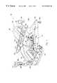
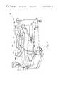
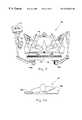
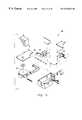
- FIGS. 1, 2 , 3 , 4 , 5 , 6 , and 7 Ashow various perspective views of the preferred embodiment of the present invention, a bariatric treatment system 100 ;
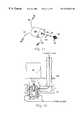
- FIG. 8shows the inflation structure 146 of the therapeutic support surface 104 of the bariatric treatment system 100 ;
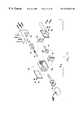
- FIGS. 9, 10 , 11 , and 12show details of the bariatric treatment system's blower and valve block assembly 137 , including details of the valve control motors 149 ;
- FIGS. 13 and 14show details of the bariatric treatment system's percussor assemblies 160 ;
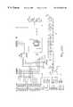
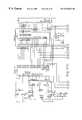
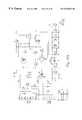
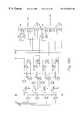
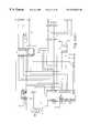
- FIGS. 15A and 15Bshow a schematic overview of the hardware and software control system 170 of the bariatric treatment system 100 ;
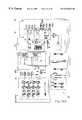
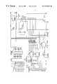
- FIGS. 16A, 16 B, 16 C, 16 D, 17 A, 17 B, 17 C, 17 D, 17 E, 18 A, 18 B, 18 C, 18 D, 18 E, 18 F, 19 A, 19 B, 19 C, 19 D, 20 A 1 , 20 A 2 , 20 B 1 and 20 B 2show various detailed schematic diagrams of the various control boards utilized in the preferred embodiment 100 , each of which is specifically referenced in the specification which follows.
- a bariatric patient therapeutic treatment system 100generally comprises a treatment bed uniquely indicated for bariatric patients, i.e, patients weighing in excess of 500 pounds, commonly in the range of 500-800 pounds.
- the frame of the bedgenerally comprises a base frame 101 , a load frame 102 and various assemblies.
- the basic mattress 104or “patient surface,” of the bed consists of a specialty low air loss mattress providing a comprehensive system of pulmonary and skin care therapies for the critically ill, immobilized patient 118 .
- Such therapiesinclude gentle side-to-side rotation of a patient, percussion (or vibration) therapy, and gentle pulsation of the air cells supporting the patient.
- the systemfurther comprises an automated CPR mode which is activated and deactivated via a plurality of CPR mode activation controls. The detailed operation of the CPR mode activation system will be apparent further herein.
- Frame assemblies 103 and accompanying patient surfaces 105provide support for the patient's head and back, buttocks, and legs and feet.
- a provided head and X-ray assembly 103 afurther comprises a mechanism for holding an X-ray cassette, detailed further herein.
- a provided seat assembly 103 bfurther comprises a set of jack motors used to adjust the angular orientation relative to seat assembly 103 b of head and X-ray assembly 103 a and leg assembly 103 c , as will be evident further herein.
- a provided foot board assembly 115is dependently attached to the leg assembly 103 c by means providing useful benefit to both the patient 118 and caregiver, also detailed further herein.
- the base frame 101generally comprises longitudinal beams and transverse elements.
- the base frame 101further comprises a plurality of floor-engaging casters 106 , conventionally journaled near the four comers of said frame.
- Locking mechanisms 114are provided for the casters 106 .
- Such locking mechanisms 114may be set to prevent either rotation or steering of the casters 106 , hence holding bed 100 stationary, as is conventional with many hospital bed frames.
- Weldmentsare provided which allow location of comer posts 108 on which may be installed intravenous injection (IV) holders or standard traction frames.
- the comer posts 108are adapted with convenient integral hand holds to facilitate patient entrance or exit of the bed 100 .
- the hand holds, as provided by the comer posts,may also assist caregivers in transport of the bed 100 .
- the bed's controlsare contained in a 360 degree swivel mounted on either foot comer post 108 a , 108 b .
- the swivelallows the controller 117 to be moved out of harm's way during transport through doors and hallways. Because the swivel provides flexibility in location and orientation of the controls, the need for multiple control panels is eliminated. Elimination of multiple control panels eliminates complicated wiring schemes and reduces overall failure modes.
- Molded plastic covers 109enhance aesthetic appeal and provide convenient locations for affixing instruction 129 or warning labels. Bumpers made of rubber or other similar materials may also be installed on covers 109 for protection of both bed and the walls and doorways of the facility where the bed 100 is used.
- the load frame 102generally comprises longitudinally disposed beams and transverse elements. Additional transverse elements are used for attachment of jack motors. The description and function of such motors will be apparent further herein.
- the load frame 102is referred to as such because it carries the entire load of the patient surface. It dependently attaches to the base frame 101 in a way that weighs that load as it is transmitted to the base frame 101 . That connection between the load frame 102 and the base frame 101 is provided by a scale mechanism well known in the art and similar to that described in U.S. Pat. No. 4,793,428, incorporated herein by this reference as though now set forth in its entirety.
- the scale mechanismgenerally comprises a pair of displacement transmitting members which are respectively connected between transverse elements via flexures.
- Each transmitting memberis attached to a base frame element via a flexure and also to a load frame element via a flexure. Attachment in this manner causes displacement of bars which are connected to the members in a cantilevered manner. Displacement, which is limited by springs, is measured in the area of the springs by linear variable differential transformers (LVDTs). Displacement measured by the LVDTs corresponds in direct proportion to the weight of the load frame and all which is supported thereby.
- a locking mechanismcomprising common hardware is desired to prevent motion of the load frame 102 relative to the base frame 101 during transport of bed 100 . This serves to prevent damage of the scale mechanism due to excessive forces as may be encountered when attempting to negotiate a short step or the like. Other conventional mechanical stops are used to limit movement and prevent damage in normal use, when the locking mechanism is not utilized.
- a raise-and-lower mechanismproduces vertical movement and Trendelenburg tilting of the seat assembly 103 b .
- a head torque arm weldment and a foot torque arm weldmentare pivotally attached to the load frame 102 .
- the seat assembly 103 bis dependently attached to weldments by members.
- the foot torque arm weldmentconnects at points to members by bushings and other necessary hardware as is well known in the art of manufacturing hospital beds.
- the head torque arm and foot torque arm weldmentsare articulated about their pivotal attachments to the load frame by extension or retraction of jack tubes (or “sleeves”) by jack motors.
- the jack motorsof the type referred to in the industry as linear actuators, attach the transverse members of the load frame by torque arm pins, themselves affixed by cotter pins.
- Extension of either tube by the corresponding motorcauses the attached weldment to pivot relative to the load frame 102 such that the connection points of the corresponding members articulate upwardly.
- Retraction of either tubewould have the opposite effect, that of lowering the members.
- Said articulationhas the effect of causing the members to raise or lower in vertical motion, thereby raising or lowering seat assembly 103 b in vertical motion.
- such articulation as raises seat assembly 103 bis said to provide a BED UP function.
- Such articulation as lowers seat assembly 103 bis said to provide a BED DOWN function.
- Articulation by one jack motor greater or less than that of the other jack motorhas the effect of establishing the patient support surface 105 in a Trendelenburg or reverse Trendelenburg treatment position.
- Trendelenburg and reverse Trendelenburg therapyis well know in the art for treatment of certain cardiac conditions and is considered an important feature for many conventional hospital beds, although the excessive weight of bariatric patients has led the art away from incorporating such features in a bariatric bed.
- the preferred embodiment 100is capable of achieving ten degrees Trendelenburg or twelve and one half degrees reverse Trendelenburg therapy. Articulation to effect such treatment is referred to as providing the TRENDELENBURG or REVERSE TRENDELENBURG function.
- the head assembly 103 ais dependently attached to the seat assembly 103 b by laterally oriented hinging. Articulation of the head and X-ray assembly 103 a about this hinge is effected by extension or retraction of a jack sleeve under the force of a jack motor.
- the jack motorof the type referred to in the industry as a linear actuator, dependently attaches to the seat assembly weldment by a pin, itself affixed by a cotter pin.
- the jack sleeveattaches to the head and X-ray assembly weldment by a pin, itself affixed by a cotter pin.
- extension of the jack sleeveis said to provide a HEAD UP function.
- Retraction of the jack sleeveis said to provide a HEAD DOWN function.
- the head assembly 103 a for the treatment systemgenerally comprises a rail encompassing a head board.
- the rail and head boardare mated together with weldments.
- the weldmentsprovide a channel for horizontal containment of an X-ray cassette.
- the transverse weldmentcombines with a hinge and another weldment to provide structural support of the head and X-ray assembly.
- An X-ray boardserves to maintain the right-angled shape of the perimetrical structure, thereby facilitating ease of insertion and removal of an X-ray cassette.
- the X-ray board and head board of the preferred embodimentcomprise a radiolucent material.
- a block and pulley systemcomprising a left block and right block, plurality of single pulleys, plurality of double pulleys and plurality of cables, allows the X-ray bar to be raised and lowered from just one of a plurality of handles, although nothing prevents two or more handles from being used, all the while maintaining the bar in a position parallel to the transverse element.
- the handlesmay lock at a plurality of vertical positions within slots in the channel members.
- the leg assembly 103 cis dependently attached to the seat assembly 103 b by a laterally oriented hinge. Articulation of the leg assembly 103 c about this hinge is effected by extension or retraction of a jack sleeve under the force of a jack motor, of the type referred to in the industry as a linear actuator, which dependently attaches to the seat assembly weldment by a pin, itself affixed by a cotter pin.
- the jack sleeveattaches to the leg assembly weldment by a pin, itself affixed by a cotter pin.
- extension of the jack sleeveis said to provide a LEGS UP function.
- Retraction of the jack sleeveis said to provide a LEGS DOWN function.
- the leg assemblyis detailed further herein with discussion of the foot board assembly.
- full extension of the head jack sleeve in order to provide full HEAD UP and simultaneous full retraction of the legs jack sleeve in order to provide full LEGS DOWNcauses conversion of the bariatric treatment system bed into a bariatric treatment system reclining chair, as depicted by FIG. 5 .
- the chair position of the bariatric treatment systemis particularly suited toward facilitation of entrance or exit of the bed by a bariatric patient.
- the seat assemblyprovides a convenient mounting location for patient restraint system weldments, as are known by those of ordinary skill in the art and may or may not be desired depending upon the specific application.
- the foot board assembly 115is dependently attached to the leg assembly 103 c .
- the leg assembly 103 cgenerally comprises a leg plate as reinforced by an “I” shaped weldment. This weldment comprises a plurality of attachment points, the purpose of which will be evident herein.
- the foot board assemblygenerally comprises a foot plate, a plurality of hinges, cushions and a heavy duty fabric cover.
- the coverin the preferred embodiment, is “Dartex P109,” commercially available from Penn-Nyla of Nottingham, England.
- the foam used for the foot plate lower cushionis a antimicrobial open-cell polyurethane foam having a relatively large density of 2.7 pounds per cubic foot and 70 pounds compression.
- the foam used for the foot plate upper cushionis a similar antimicrobial open-cell polyurethane, but is less dense than the lower cushion, having a density of 2.0 pounds per cubic foot and 41 pounds compression.
- Both cushionsare wedge-shaped, with their greater thicknesses (roughly 1.75 inches and 0.5 inch, respectively) being distal to the hinge. The relative characteristics of these foam cushions serve their varied purposes.
- a rigid foot board in combination with a chair position featurefacilitates bariatric patient care.
- measuresare taken to ensure such foot boards are not used as a step when exiting the bed, presumably for safety reasons in view of the excessive weight of bariatric patients.
- the present inventiongoes against such teachings by providing a foot board which is adapted to be used safely as a step for bariatric patients.
- the foot board assembly 115attaches to the leg assembly 103 c by such means as to provide gradual increase in rigidity as weight is applied to the foot cushion 116 , so as to provide adequate support of the bariatric patient entering or exiting bed yet avoiding fixed resistance to a sudden increase in force.
- the primary attachment of the foot board assembly to the leg assemblyis by a hinge through weldments on the foot board assembly and a plurality of holes in a weldment of the leg assembly. Articulation about this hinge is constrained by dampening cylinders and a spring, as detailed further herein.
- the springin compression, attaches to the leg assembly weldment by a pin, itself affixed by a cotter pin.
- the springattaches to the foot board assembly weldment also by a pin, itself affixed by another cotter pin.
- a hydraulic cylinderof the type which dampens primarily in compression, attaches to the leg assembly weldment by a pin, itself affixed by a cotter pin.
- the compression hydraulic cylinderattaches to the foot board assembly weldment also by a pin, itself affixed by another cotter pin.
- a hydraulic cylinderof the type which dampens primarily in tension, attaches to the leg assembly weldment by a pin, itself affixed by cotter pin.
- the tension hydraulic cylinderattaches to the foot board assembly weldment also by a pin, itself affixed by another cotter pin.
- the particular cylinder selected for compression dampeningis, in the preferred embodiment of the present invention, an adjustable cylinder having a two-inch stroke and available through Enidine of Orchard Park, N.Y., part number (LR)OEM 1.5M ⁇ 2.
- the particular cylinder selected for tension dampeningis, in the preferred embodiment of the present invention, an adjustable cylinder having a four-inch stroke and also available through Enidine of Orchard Park, N.Y., part number ADA 510T.
- the particular spring selectedis, in the preferred embodiment of the present invention, a medium load, round wire spring available through Lee Spring Company of Brooklyn, N.Y., part number LHL-1 500A-9MW.
- the compression dampening hydraulic cylinderUnder the weight of a bariatric patient, the compression dampening hydraulic cylinder increasingly resists articulation of the foot board assembly about the attaching hinge. Gradually, resistance will increase as more weight is applied by the patient. In this manner, the foot board assembly is able to provide increasingly rigid support of the bariatric patient while minimizing any risk of snapping under the weight of a typical bariatric patient. Further if a bariatric patient should apply weight onto foot board at excessive speed, the dampening action of the compression dampening hydraulic cylinder may serve to prevent injury to the patient's knees and legs. Once weight is removed from foot board (such as once the patient has completely exited the bed), the spring returns the foot board assembly to its original position with respect to the leg assembly. The tension dampening hydraulic cylinder resists the return motion of the spring. Such dampening helps prevent snapback of the foot board assembly, which might otherwise present safety hazards.
- the cushionsnot only enhance patient comfort but can also cushion engagement of the foot board with the floor as the patient exits or enters the bed. Additionally, in case a caregiver is unalert and places a foot beneath foot board assembly, and a patient's weight does cause the foot board assembly to contact the caregiver's foot, heavy padding of the lower cushion distributes the weight and cushions the caregiver's foot to help prevent excessive discomfort or physical injury.
- Pins 134held in position beneath the foot board assembly by nuts, may be placed in a release position so as to allow the foot plate to articulate about a secondary attachment hinge. Said release allows the patient support foot cushion to lie coplanar with the leg cushion. This may be desirable when the bed surface is in a horizontal position and the caregiver wishes to minimize pressure against the patient's feet.
- the left side rail 110 agenerally comprises a metal frame encased by molded plastic covers 111 a .
- the frameis generally dependently attached to a side rail mounting plate through weldments and shafts, substantially identical those fully enabled in U.S. patent application Ser. No. 08/382,150, filed Jan. 31, 1995, hereinabove incorporated by reference.
- These weldments and shaftsare themselves major components of a mechanism for raising and lowering of the side rail assembly. Said mechanism is also utilized for lateral translation of the side rail assembly, thereby extending or compressing the lateral dimension of the bariatric treatment system. Details of the manufacture and use of this mechanism will be evident further herein.
- the aforementioned mechanismcomprises those elements necessary for raising, lowering or laterally translating the left side rail.
- Weldmentsare dependently cantilevered, in fixed relation, from shafts.
- the shaftsfreely rotate and slide laterally within bushings.
- These bushingsare dependently attached to a mounting plate in fixed position.
- Pawlsare connected by a rod in such manner as to require coordinated motion of said pawls.
- a plurality of rectangular pegsform teeth on the shafts in such a manner as to form a ratchet mechanism with the pawls.
- the ratchet mechanismallows the side rail to be raised by lifting only from a lowest TRANSPORT position to either a middle LOWERED position or the upper RAISED position.
- a provided release leverIn order to lower the side rail from the RAISED position to the LOWERED position or from the LOWERED position to the TRANSPORT position, a provided release lever must be manually articulated in order to cause release of the pawls from the teeth of the shafts.
- the side railmay be freely translated laterally outward from the center of the bed. This configuration is referred to as EXTENDED in the preferred embodiment.
- EXTENDEDFrom the EXTENDED position, the side rail may be returned to the RAISED position.
- the side railwhen in the EXTENDED RAISED position, must be lowered prior to translation back toward the center of bed, the NORMAL position.
- the side rail of the preferred embodimentmay be further translated toward the center of the bed, to a location beneath the seat assembly, thereby. maximally reducing the overall lateral dimension of the bed.
- the reduction in lateral width attainableis sufficient so as to be able to fit the bed through a standard hospital doorway.
- the bariatric patient 118is often of such limited mobility as to make it impracticable for such a patient to utilize bed function controls mounted on a side rail.
- the preferred embodiment of the present inventionincludes a hand held bed function control pendant 124 which comprises a molded plastic body encompassing necessary electronic hardware, as is common in the industry, and a clip 125 for easy stowage upon a side rail 110 .
- the pendant 124includes a plurality of push button membrane switches allowing the patient 118 to control such functions as BED UP, BED DOWN, HEAD UP, HEAD DOWN, LEGS UP and LEGS DOWN, as have been previously detailed.
- the pendant 124attaches to the swivel mounted main control 117 panel by a cord 126 and plug.
- An infrared hand held control 127is also provided in the preferred embodiment.
- the infrared control 127comprises the same functionality as does the hard-wired pendant 124 and also comprises a similar attachment clip 128 . It communicates with the master controller through an infrared detector, and associated hardware and software, mounted on the underside of the swivel mounted main control panel 117 .
- a serial bus architectureemployed extensively in the preferred embodiment of the present invention, allows simple parallel implementation of the three control units 117 , 124 , 127 .
- the therapeutic structure of the bariatric treatment system 100generally comprises a patient support surface, blower and valve box assemblies, and a patient rotation angle sensing system.
- the patient support surface 105normally covered by a sheet, generally comprises a plurality of patient support air cushions 130 - 133 , turning air bladders 135 , patient restraining bladders 136 and a percussor bladder. All air bladders in the preferred embodiment comprise a polyurethane coated, impermeable, heavy duty fabric.
- the patient support air cushions 130 - 133are inflated by air which has been transmitted through a plurality of polyethylene hoses from a blower and valve assembly 137 .
- the plurality of hosesare connected to the cushions sectionally, hence compartmenting air flow into the head section 130 , back section 131 , torso section 132 and legs section 133 .
- the cushions of the back 131 , torso 132 and legs 133 sectionsare supplied with air from the hoses in alternating fashion. This allows the patient 118 supported upon the surface to receive pulsation therapy as is well known in the treatment and prevention of bedsores, or decubitus ulcers, and other pressure related complications of extended confinement to hospital beds.
- Pulsation therapyis accomplished by first reducing pressures through the hoses feeding every other bladder in the desired pulsation region, hence deflating the attached cushions. Upon attaining the maximum desired deflation in these cushions air flow is restored through the hoses, again inflating the connected cushions. Simultaneously, with the re-inflation of the first deflated cushions; pressure is decreased in each cushion adjacent those being reinflated, within the pulsation region, by decreasing flow through the hoses connected thereto. Upon attaining the maximum desired deflation in this second group of cushions, and simultaneously the maximum desired inflation in the first group of cushions, the cycle is reversed and repeated.
- maximum desired inflation and deflationis determined by the desired therapy intensity which in the preferred embodiment is caregiver selectable as LOW, MEDIUM or HIGH PULSATION.
- this pulsationis available with cycle periods from two to forty minutes. Separation of the air cushions of the back section 131 , torso section 132 and legs section 133 also allows independent adjustment of maximum pressures in each region thus allowing more optimal minimization of pressure points against the patient.
- the cushions 130 of the head sectionare supplied with air taken from splices 138 into the those hoses which supply air to the back section.
- the airis first fed into a shuttle and check valve system 139 , wherein any pulsation which may be activated is dampened out.
- a shuttle valve 140acts to pass the highest pressure air from either of the two lines to a restricted flow port 141 .
- a check valve 142is provided which allows air flowing to the head section 130 to only pass through the flow port 141 .
- the check valve 142allows flow from the head section 130 to pass through the flow port 141 as well as through a much larger port about the check valve 142 .
- the restricted, or dampened, air flowis then directed into the cushions 130 of the head section which exhibit only minimal pulsation effects.
- the patient restraint bladders 136are also inflated through polyethylene hoses which originate from the same blower and valve assembly 137 as do the hoses to the patient support cushions 130 - 133 .
- these bladders 136are inflated from a hose spliced into one set of hoses feeding the torso section 132 .
- a check valve 143is provided which prevents the restraint bladders 136 from deflating with pulsation therapy.
- a plurality of bladders 119is provided for expanded patient support when the bariatric treatment system 100 is in the EXTENDED side rail position, as described hereinabove.
- the bladders 119receive inflating air through hoses spliced into the set of hoses feeding the torso section 132 not spliced to the restraint bladders 136 .
- a check valve 144such as that utilized for the restraint bladders 136 is provided to prevent deflation of the expanded support bladders 119 during pulsation therapy in the torso section 132 .
- these bladdersare disconnected from their supply hoses and tucked away beneath the back 105 b and legs 105 c sections of the patient support system 104 .
- a manual three way valve 145is provided to prevent uncontained discharge of air during the condition where these hoses are disconnected. Except for the modifications as noted hereinabove, the construction and operation of the foregoing inflation structure 146 is substantially identical that disclosed in U.S. patent application Ser. No. 08/673,442, filed Jun. 28, 1996, hereinabove incorporated by reference.
- the inflation structure 146 for the turning bladders 135generally provides for a LEFT ROTATION and a RIGHT ROTATION turn of the patient.
- a left rotation turn of the patientaccomplished by inflation of the left turning bladder 135 a through a first hose from the valve block 137 while simultaneously exhausting air in the right rotation bladder 135 b through a second hose from the valve block 137 .
- a right rotation turn of the supported patient 118is accomplished by inflation of the right turning bladder 135 b through the second hose while simultaneously exhausting air in the left turning bladder 135 a through the first hose.
- the best mode embodiment of the bariatric treatment system's valve block assembly 137generally comprises a manifold 147 with a motor mounting plate 148 s supported a distance separated from the manifold by a plurality of industry standard stand-offs.
- Dependently mounted upon the motor mounting plateis a plurality of 12-volt, reversible direction, direct current motors 149 .
- Each such motor 149is provided with electrical connection from a positive terminal 150 and a negative terminal 151 through a connector to a relay board, understood further herein.
- Each motor 149is further provided with a chassis ground connection 152 .
- the valve block assembly 137comprises a plurality of air tubes 153 which provide air flow to the patient supporting air cushions 130 - 133 , extension and restraint bladders 119 , 136 , and turning bladders 135 as hereinabove described.
- Each valve control motor 149further comprises a valve control motor shaft 154 connected to a coupling 155 by a pin 156 , which coupling 155 further connects to a valve screw 158 by another pin 157 .
- spaceis conserved by utilizing a valve screw 158 which is of adequate diameter to fit coaxially over the coupling 155 , hence eliminating the need for an additional shaft. This reduces the longitudinal dimension of the valve block assembly 137 while utilizing only that space otherwise required due to the diameter of the valve motors 149 .
- Connection of each shaft 154 to its corresponding valve screw 158 via a coupling 155 and pins 156 , 157allows floating of the valve screw 158 , promoting self-alignment with the valve spool 159 . This design simplifies manufacture and increases reliability of the valve block assembly's operation.
- the valve motorturns in the valve opening direction
- the valve screwdrives the valve spool away from the valve motor creating a flow path between an internal cavity and the corresponding hose connection tube.
- the cavityis pressurized by a blower within a provided blower and valve block housing.
- this blowermay be mounted separately from the housing and cavity. In such an embodiment, which may be advantageous for conservation of space, the blower would connect to the cavity via an air hose.
- Air flow between the cavity and tubeserves to inflate any air bladders which may be connected.
- the applicationshows the valve spool in the closed position so as to block any flow into or out of the corresponding tube.
- the applicationalso shows the valve spool in the exhausting position.
- the valve motorturns in the valve exhausting direction
- the valve screwdrives the valve spool toward the valve motor creating a flow path between the corresponding tube and the atmosphere.
- the exhausting positionair escapes to the atmosphere from whichever bladders may be connected to the tube. Flow to the atmosphere takes place between the manifold and motor mounting plate.
- valves making use of spool valvesare preferred over embodiments which attempt to make use of poppet valves, or other forms of valves which rise perpendicularly to or from their seats.
- Use of “V” shaped slots in the valve spool boreallows fine control of air flow due to the gradual opening of the air port which is provided by such slots.
- the cavity of the valve block assemblyis modified to allow insertion of a nylon thumb screw in order to limit the opening motion of the valve spools under control of the two valve motors utilized to control air flow into and out of the turning bladders.
- the thumb screwmaintains the valve spool position within the region of control of air flow. Such maintenance of the region of control is necessary for the efficient operation of the rotation function control algorithm, detailed further herein.
- the construction and operation of the valve block assembly 127is substantially identical that fully enabled in U.S. patent application Ser. No. 08/673,442, filed Jun. 28, 1996, hereinabove incorporated by reference.
- the percussor system 160 of the bariatric treatment system 100generally includes a blower 161 , a valve block 162 (also referred to as a “percussion body”) and a solenoid 163 .
- the blower 161is powered by an internal three speed alternating current motor. Said motor 161 is controlled by an internal circuit board in response to inputs received through direct current channels through a transmission line assembly.
- the three speeds of the blowerallow for three levels of intensity for percussion therapy, LOW, MEDIUM and HIGH PERCUSSION, as will be evident further herein.
- the percussor valve block 162generally comprises a longitudinally articulable rod 164 upon which are mounted first 165 and second valve disks 166 .
- the position of the rod 164determines the air flow path through the valve block 162 at any given instance. There are generally two conditions. In the first condition, the rod 164 is biased, by a provided wire spring 167 , distally from a provided solenoid 163 . In this position, the first disk 165 is held away from its seat 168 and the second disk 166 mates with its seat 169 , allowing airflow into the percussor valve block 162 to exhaust partially to the atmosphere and partially to the percussor bladder.
- the solenoid 163pulls the rod 164 toward itself, thus causing the first disk to mate with its seat and the second disk to be removed from its seat.
- airflow into the valve block from the bloweris fully exhausted to the atmosphere. Further airflow form the percussion bladder is also allowed to exhaust to the atmosphere.
- the blower 161operates continuously at a given speed, depending upon the intensity of percussion desired. By splitting the airflow while inflating the percussion bladder, the blower is prevented from entering a dead-head condition in which flow is stalled. This ensures maximum intensity of percussion action as well as prevents overheating of the blower at lower percussion frequencies.
- the therapeutic structure of the bedfurther comprises a hinging system wherein a plurality of straps, comprising heavy duty webbing, are arranged in a criss-cross fashion along the longitudinal axis of the patient support sub-frame.
- This hinging systemis exactly like that disclosed in U.S. patent application Ser. No. 08/673,442, filed Jun. 28, 1996, hereinabove incorporated by reference.
- the turning bladders 135 utilized in the presently preferred embodiment of this invention 100are substantially similar those of U.S. patent application Ser. No. 08/673,442, filed Jun. 28, 1996, hereinabove incorporated by reference, except that only two are provided and these are modified for maximum turning efficiency under a bariatric patient.
- internal bafflesare provided which maintain the bladder cross section in a right triangular shape with a smaller angle much less than the greater angle. In this manner, the bladder is prevented from assuming a cylindrical shape and thereby places maximum area (that of the hypotenuse panel) in contact with the underside of the patient support surface.
- the zippering and other features described in application Ser. No. 08/673,442remain as disclosed.
- the patient rotation angle sensing systemis identical that disclosed in U.S. patent application Ser. No. 08/673,442, filed Jun. 28, 1996, hereinabove incorporated by reference.
- the angle sensor therein describedis further utilized in two additional places in this present invention.
- Angle sensors 113are placed on the articulating members connecting the load frame to the mid-frame.
- System softwareperforms trigonometric calculations upon the measured angle data in order to accurately estimate the exact patient orientation. This information allows the bariatric treatment system to assume a number of given positions, such as TRENDELENBURG and others, automatically at the press of a control panel button.
- a power inverter, rechargeable batteries, circuit breaker, relay and connecting brackets and the likeare maintained in the lower frame assembly.
- Such componentsprovide the bariatric treatment system with standard AC power supply and, alternately, an AC-like power supply from the rechargeable batteries.
- the power systemis identical to that disclosed in U.S. patent application Ser. No. 08/673,442, filed Jun. 28, 1996, hereinabove incorporated by reference.
- the functional aspects of the bariatric treatment system 100may be summarily described as comprising a master board and display system 171 with infrared receiver board 172 , a communications logic board 173 , a sensor board 175 , a relay board 176 , a percussor board 174 , a scale board, an infrared transmitter system 179 , and a power supply and battery backup system 178 , all in operable communication with a plurality of jack motors and the therapeutic patient treatment system along with various pressure sensors, angle sensors, infrared sensors and limit switches, integral therewith.
- the 80C32 microcontrolleroperates at a clock rate of 11.0592 mega-Hertz (MHz), as provided by an on-board crystal oscillator circuit. As is understood by those of ordinary skill in the art, clocking at 11.0592 MHz allows generation of industry standard baud rates, utilized throughout the bariatric treatment system for serial communications between the various provided integrated hardware and software control circuits.
- the 80C32includes an integral universal asynchronous receiver and transmitter (UART) for serial communications with peripheral boards, as will be understood further herein.
- the master boardalso includes a WaferScale Integration (WSI) device number PSD313 programmable microcontroller peripheral with erasable memory, commercially available from WaferScale Integration, Inc. of Fremont, Calif., which comprises a 128 kilobyte (Kbyte) ultraviolet erasable programmable read only memory (UV EPROM), of which 64 Kbyes are utilized by the 80C32 for program storage, and a 2 Kbyte static random access memory (SRAM), utilized by the 80C32 for storage of software control variables.
- the PSD313also provides programmable arrays, utilized by the master board software for memory mapping and creation of data input and output (I/O) ports.
- the master boardincludes a trademark “BENCHMARQ” device number bq3287EMT real-time clock (RTC) module, commercially available from Benchmarq Microelectronics, Inc. of Carrollton, Tex.
- the bq3287EMTis utilized by the 80C32 for error logging and time and date stamping of patient weight information, each understood further herein.
- the bq3287EMTalso provides 242 bytes of non-volatile SRAM, utilized by the 80C32 for storage of system parameters and diagnostic error logs.
- a trademark “DALLAS SEMICONDUCTOR” device number DS1232 micromonitor chipcommercially available from the Dallas Semiconductor Corporation of Dallas, Tex., is utilized by the 80C32 as a watchdog timer, as is understood by those of ordinary skill in the art.
- the DS1232provides a hard reset to the 80C32 in the event of a software failure, as will be understood further herein.
- the display system of the bariatric treatment systemgenerally comprises a plurality of membrane switches and a vacuum fluorescent display (VFD), commercially available from Futaba of, configured for six lines of 40 characters per line. Interface from the master board to the membrane switches is directly provided for by external data ports of the 80C32.
- the membrane switchesare electrically arranged in a matrix. Depression of any single membrane switch shorts one row to one column.
- the 80C32successively writes to each row of membrane switches while rapidly reading each column of membrane switches. In this manner, the 80C32 determines whether any row and column is shorted together, thereby indicating depression of a particular membrane switch.
- M68HC11single-chip microcontroller
- the M68HC11formats display driver data from the 80C32 and then passes the formatted data to the VFD through a 34 pin flat ribbon connector.
- RS-485 busis the recommended standard of the Electronic Industries Association (EIA) for specifying the electrical characteristics of generators and receivers used in balanced digital multipoint systems.
- EIAElectronic Industries Association
- the RS-485 standardis also sometimes referred to as the EIA-485 standard, without loss of meaning.
- a discretely implemented low power, dual metal oxide semiconductor field effect transistor (MOSFET) driver circuitprovides interface from the master board to the KCI bus.
- MOSFETmetal oxide semiconductor field effect transistor
- communications signals on the RS-485 bus and the KCI busare logically mirrored such that all signals appearing on one bus are simultaneously transmitted on the other.
- Signals from the master boardare simultaneously transmitted by direct electrical connection to both busses.
- Signals to the master boardwhich are logically identical, arrive either from the RS-485 bus or from the KCI bus, according to the placement of a jumper switch on the master board.
- the master boardextensively utilizes memory mapping—a listing of all the memory assignments as implemented in the program software, categorized as either program space or data space.
- Memory mappingallows the 80C32 to identify the amount of memory required, the locations of data or subroutines, and those memory locations not allocated or utilized.
- the memory mappingallocates 64 Kbyes as program space and 64 Kbyes as data space which also includes I/O port allocations.
- the 80C32reads system program instructions from the program space and, as required, reads from and writes to the various peripheral devices, as is understood by those of ordinary skill in the art, in order to effect or utilize system parameters, error logs, membrane switch I/O, VFD driver data and software control variables.
- Table 1Master Board Memory Mapping. This table specifies whether the 80C32 reads (R), writes (W) or reads and writes (R/W) particularly addressed, as delineated in hex (Address Range), system program instructions (PROG) or data and I/O (DATA) out of or into the space (Space) allocated to a particular device (Device).
- the tablealso includes an abbreviated summary of the function (Function) implemented under each assignment.
- FIGS. 16A, 16 B, 16 C, and 16 DA detailed schematic drawing of the master board 171 is provided at FIGS. 16A, 16 B, 16 C, and 16 D This detailed schematic is enabling, to those of ordinary skill in the art, of the above-recited structure and function.
- the communications logic board 173may be summarily described as the central node of a star architecture implementation of the dual communications bus structure (RS-485 and KCI) of the preferred embodiment of the present invention. This implementation is effected through provision of six six-pin modular connectors for RS-485 bus connectivity, six eight-pin modular connectors for KCI bus connectivity, and one DB-9 connector and three four-pin modular connectors for RS-232 serial communication line connectivity.
- RS-232is the EIA recommended standard for single-ended data transmission, that is data transmission using only one signal, at relatively low data rates (up to 20 kilo-bits per second (Kbps)) over short distances (typically up to ⁇ 50 feet).
- the boardimplemented on two four layer PCBs each having power and ground planes, creates a logical mirror between the RS-485 bus and the KCI bus and between these busses and two provided RS-232 serial communications jacks.
- the two PCBs of the communications logic boardelectrically interconnected through a 32 wire flat ribbon cable, may be stacked or placed side-by-side according to the physical constraints of the particular embodiment in which they are implemented.
- An LM294OCT-5 linear voltage regulatorsupplies regulated 5-Vdc power to the communications logic board.
- the communications logic board of the preferred embodiment of the present inventionis designed about a trademark “ALTERA” device number EPM7032 programmable logic device (PLD), commercially available from the Altera Corporation of San Jose, Calif.
- the EPM7032operates at a clock rate of 3.6864 MHz, as provided by an on-board crystal oscillator circuit. As is understood by those of ordinary skill in the art, clocking at 3.6864 MHz is compatible with implementations of industry standard baud rates as are utilized throughout the bariatric treatment system.
- the EPM7032is custom designed to create a logical mirror between the RS-485 bus, the KCI bus, and the RS-232 serial communications lines.
- TTLtransistor transistor logic
- the sampled input datais transmitted on the outputs of the two non-sampled lines. This process is very rapid, the only delay being one clock cycle and propagation time. Because the EMP7032 is clocked at a much higher rate than the maximum data transmission rate of 19.2 Kbaud, the delay incurred through the mirroring operation is only about five ten-thousandths of a bit.
- a trademark “NATIONAL SEMICONDUCTOR” device number DS36276 FAILSAFE multipoint transceivercommercially available from the National Semiconductor Corp. of Santa Clara, Calif., is utilized on the communications logic board to implement a six-wire RS-485 bus through the provided RS-485 bus modular connectors.
- the DS36276converts TTL voltage levels (0 to 5-Vdc) to differential voltage levels, and vice versa.
- a discretely implemented MOSFET driver circuitprovides interface from the communications logic board to the KCI bus through the provided KCI bus modular connectors.
- the MOSFET driver circuitconverts TTL voltage levels to voltage levels compatible with the KCI standard, and vice versa.
- the interface from the communications logic board and the RS-232 serial communications linesis designed about a trademark “INTEL” device number 87C52 microcontroller, commercially available from the Intel Corporation of Santa Clara, Calif.
- the 87C52 microcontrolleroperates at a clock rate of 11.0592 MHz, as provided by an on-board crystal oscillator circuit.
- the 87C52includes an integral UART for serial communication of RS-232 I/O to or from the EMP7032. Because, in the preferred embodiment of the present invention, the RS-485 and KCI busses operate at 19.2 Kbaud and the RS-232 serial communications lines may operate at higher or lower data rates, depending upon the peripheral device connected thereto, buffering may be necessary, on a case-by-case basis, between the 87C52 and the EMP7032.
- a trademark “HITACHI” device number HM62256 high-speed CMOS SRAMprovides 32 Kbytes of static memory for buffering between the 87C52 and the EMP7032. Such buffering is required as many serial devices which may be utilized operate at baud rates different form the RS-485 and KCI busses.
- the serial communication linesare implemented with four trademark “MAXIM” device number MAX239 multi-port RS-232 drivers.
- a Phillips Semiconductor device number SC26C94 Quad UARTprovides interface between the SC26C94 and the 87C52.
- Transorbsare provided on each serial communication line in and out of the communications logic board for protection against power surge and electro-static discharge (ESD).
- Each connectorfurther comprises a separately fused 12-Vdc power supply connection.
- one of the RS-232 serial linesis used to connect to the battery backup system, or inverter module; three of the KCI serial bus connectors are used to connect the percussor board, sensor board, and scale board; and two of the RS-485 serial bus connectors are used to connect the relay board and master board.
- FIGS. 17A, 17 B, 17 C, 17 D, and 17 Eprovide a detailed shematic drawing of the communications logic boards, fully enabling to those of ordinary skill in the art.
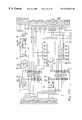
- FIGS. 18A, 18 B, 18 C, 18 D, 18 E and 18 Fprovide a detailed schematic of the sensor board.
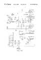
- FIGS. 19A, 19 B, 19 C and 19 Dprovide a detailed schematic of the relay board.
- FIGS. 20 A 1 and 20 A 2provide a detailed schematic of the infrared receiver board.
- FIGS. 20 B 1 and 20 B 2provide a detailed schematic of the infrared transmitter board. Each of these schematics is fully enabling to those of ordinary skill in the art.
- the master board softwarecontrols 19.2 Kbaud serial communications to the six peripheral boards within the bariatric treatment system.
- the softwareis responsible for initiating and terminating all serial communications.
- the softwaremonitors and updates numerous global and local variables based upon input from the six peripheral boards and switch inputs from the membrane switches of the control units.
- the softwarealso writes menu screens to a Vacuum Fluorescent Display (VFD) by writing display data to a register which serves as a mailbox for another on-board processor which is tasked with updating the VFD.
- VFDVacuum Fluorescent Display
- the softwareincludes menu screens for setting up various therapies, including rotation, pulsation, percussion, inflation, and deflation of the seat section.
- the softwarefurther includes diagnostic screens for viewing error logs, software versions of software installed on the peripheral boards, membrane switch testing, mattress air hose plumbing testing, real-time clock time and date adjustments, and sensor screens for viewing the data from the peripheral boards in real-time.
- the softwareincludes switch handling code to process inputs from the membrane switches of the bed's swivel mounted control panel.
- the softwareincludes safety features to cancel rotation due to various bed position conditions and includes code for emulation of the standard C programming language input/output “printf( . . . );” command, including decimal, integer, and hexadecimal conversion characters.
- the sensor board softwarecontrols the bed's air system directly with motor control code for the bed's valve box, blower control code for the bed's main air blower, and therapy control code for maintaining and controlling therapies such as Pulsation, Rotation, Instant Inflation (INSTAFLATE), and Seat Deflate.
- This softwarealso reads the analog inputs from up to 16 analog sensors and switches and utilizes these inputs in the process of controlling the bed's multiple therapies. Such inputs include an Auxiliary CPR Switch for shutting off the air system in the event that serial communications with the master board are terminated.
- Therapiesare generally, but not exclusively, controlled by the software by comparing a set of target pressure and angle values with the actual pressure and angle values as seen by the analog to digital converter, and then using various software functions to adjust the air pressures in various bladders as required.
- a serial protocolis included in the software to enable 19.2 Kbaud communications by the sensor board with the master board.
- the percussor board softwarecontrols the intensity of the percussor blower, the frequency of the percussor solenoid (which in turn determines the frequency of percussion), and the activation of both the blower and the solenoid.
- the bloweris controlled with a pulse-width signal which is generated with an internal microcontroller timer.
- the softwareincludes a diagnostic mode for testing the microcontroller ports and the board's RAM.
- a communications time-out counteris also included in the software to provide a fail-safe response during board operation in cases where communications are momentarily or completely lost.
- a serial protocolis included in the software to enable 19.2 Kbaud communications by the percussor board with the master board.
- the scale board softwaregenerates a 3600 Hz on-board clock pulse to stimulate two Linear Variable Differential Transformers (LVDTs) and switch a signal rectifier.
- the softwarecontrols and reads the analog output in 16-bit digital format from an on-board Analog-to-Digital Converter (ADC).
- ADCAnalog-to-Digital Converter
- the digital outputis converted into English pounds and Metric kilograms by the master board software.
- a serial protocolis included in the software to enable 19.2 Kbaud communications by the scale board with the master board.
- the relay board softwareprovides user control of the four on-bed jack motors for articulation of the three bed surface sections.
- the softwarealso provides the user with four programmed bed positioning sequences including Patient Exit, Cardiac Chair, CPR, and One-Position Weighing for the Scale.
- the softwarecooperates with the sensor board software to provide for deflation of the bladders beneath the patient's legs during Patient Exit. In this manner, any tendency for the patient to slide while exiting the bed is sharply reduced.
- a serial protocolis included in the software to enable 19.2 Kbaud communications by the relay board with the master board.
- a communications time-out counteris also included in the software to provide a fail-safe response during board operation in cases where communications are momentarily or completely lost.
- Angle sensor data from the sensor boardis utilized by the relay board software to calculate the height of the head and foot section jack, and to calculate the Trendelenburg angle of the bed.
- the high resolution angle control algorithmis implemented in the same manner as that disclosed in U.S. patent application Ser. No. 08/673,442, filed Jun. 28, 1996, hereinabove incorporated by reference.
- the preferred embodiment of the invention herein disclosedis designed to offer a comprehensive system of pulmonary and skin care therapies for the critically ill, immobilized patient. Simple procedures have been developed to allow the caregiver and/or patient maximum means to access and operate the myriad functions offered.
- the operation of these controlsis substantially identical that disclosed in U.S. patent application Ser. No. 08/673,442, filed Jun. 28, 1996, hereinabove incorporated by reference.
- the operationis summarized in Appendix I, a duplication of the Quick Reference Guide for the commercial product representing the presently preferred embodiment of the invention disclosed herein. It is believed that this Quick Reference Guide is being published on a date commensurate with the filing of this present application.
- Appendix Iincluding all drawings and other parts thereof, is incorporated herein as though now set forth in it's entirety
Landscapes
- Health & Medical Sciences (AREA)
- Nursing (AREA)
- Life Sciences & Earth Sciences (AREA)
- Animal Behavior & Ethology (AREA)
- General Health & Medical Sciences (AREA)
- Public Health (AREA)
- Veterinary Medicine (AREA)
- Physics & Mathematics (AREA)
- General Physics & Mathematics (AREA)
- Invalid Beds And Related Equipment (AREA)
Abstract
Description
| TABLE 1 |
| Master Board Memory Mapping |
| R/W | Address Range | Space | Device | Function |
| R | 0-xFFFFh | PROG | PSD313 | Program instruction |
| R/W | 0-x1FFh | DATA | bq3287EMT | System parameters/ |
| error logs | ||||
| R/W | x200h-x3FFh | DATA | Ext. Data | Membrane switch I/O |
| Ports | ||||
| W | x400h-x5FFh | DATA | M68HC11 | VFD driver data |
| R/W | x2000h-x27FFh | DATA | PSD313 | Software control |
| variables | ||||
| R | x4000h-xFFFFh | DATA | PSD313 | Reserved |
Claims (21)
Priority Applications (4)
| Application Number | Priority Date | Filing Date | Title |
|---|---|---|---|
| US08/972,209US6536056B1 (en) | 1996-11-18 | 1997-11-17 | Bariatric treatment system and related methods |
| JP52389698AJP2002516581A (en) | 1996-11-18 | 1997-11-17 | Obesity treatment device and related methods |
| US10/351,711US6904631B2 (en) | 1996-11-18 | 2003-01-27 | Bariatric treatment system and related methods |
| US11/151,042US7346945B2 (en) | 1996-11-18 | 2005-06-13 | Bariatric treatment system and related methods |
Applications Claiming Priority (3)
| Application Number | Priority Date | Filing Date | Title |
|---|---|---|---|
| US3140896P | 1996-11-18 | 1996-11-18 | |
| US3166696P | 1996-11-21 | 1996-11-21 | |
| US08/972,209US6536056B1 (en) | 1996-11-18 | 1997-11-17 | Bariatric treatment system and related methods |
Related Child Applications (1)
| Application Number | Title | Priority Date | Filing Date |
|---|---|---|---|
| US10/351,711ContinuationUS6904631B2 (en) | 1996-11-18 | 2003-01-27 | Bariatric treatment system and related methods |
Publications (1)
| Publication Number | Publication Date |
|---|---|
| US6536056B1true US6536056B1 (en) | 2003-03-25 |
Family
ID=27363873
Family Applications (2)
| Application Number | Title | Priority Date | Filing Date |
|---|---|---|---|
| US08/972,209Expired - LifetimeUS6536056B1 (en) | 1996-11-18 | 1997-11-17 | Bariatric treatment system and related methods |
| US10/351,711Expired - Fee RelatedUS6904631B2 (en) | 1996-11-18 | 2003-01-27 | Bariatric treatment system and related methods |
Family Applications After (1)
| Application Number | Title | Priority Date | Filing Date |
|---|---|---|---|
| US10/351,711Expired - Fee RelatedUS6904631B2 (en) | 1996-11-18 | 2003-01-27 | Bariatric treatment system and related methods |
Country Status (1)
| Country | Link |
|---|---|
| US (2) | US6536056B1 (en) |
Cited By (82)
| Publication number | Priority date | Publication date | Assignee | Title |
|---|---|---|---|---|
| US20030208847A1 (en)* | 1996-11-18 | 2003-11-13 | Kinetic Concepts, Inc. | Bariatric treatment system and related methods |
| US20040128765A1 (en)* | 1999-12-29 | 2004-07-08 | Hill-Rom Services, Inc. | Foot controls for a bed |
| US20040216235A1 (en)* | 2001-11-22 | 2004-11-04 | Rees John Christopher | Bed |
| US20040226091A1 (en)* | 1997-08-08 | 2004-11-18 | Hill-Rom Services, Inc. | Hospital bed |
| US20050222544A1 (en)* | 2004-04-05 | 2005-10-06 | Weston Richard S | Flexible reduced pressure treatment appliance |
| US20050229321A1 (en)* | 1996-11-18 | 2005-10-20 | Kci Licensing, Inc. | Bariatric treatment system and related methods |
| US20060014126A1 (en)* | 2004-06-15 | 2006-01-19 | Healing Solutions, Llc | System for tutoring users of a medical apparatus on the operation of that medical apparatus |
| US20060026768A1 (en)* | 2004-08-04 | 2006-02-09 | Chambers Kenith W | Hospital bed |
| US20060053555A1 (en)* | 2004-09-13 | 2006-03-16 | Craig Poulos | Bed having fixed length foot deck |
| US20060053562A1 (en)* | 2004-09-13 | 2006-03-16 | Craig Poulos | Mattress for a hospital bed |
| US20060059621A1 (en)* | 2004-09-13 | 2006-03-23 | Craig Poulos | Siderail for hospital bed |
| US20060059624A1 (en)* | 2004-09-13 | 2006-03-23 | Craig Poulos | Expandable width bed |
| US20060085914A1 (en)* | 2004-06-14 | 2006-04-27 | Steve Peterson | Adjustable bed for bariatric patients |
| US20060090261A1 (en)* | 1995-01-31 | 2006-05-04 | Kci Licensing, Inc. | Bariatric bed apparatus and methods |
| US20060101581A1 (en)* | 2004-10-29 | 2006-05-18 | Blanchard Frederick W | Patient support apparatus |
| US20060117482A1 (en)* | 2004-12-07 | 2006-06-08 | Branson Gregory W | Touch screen control for lateral rotation of a hospital bed mattress |
| WO2006060796A2 (en) | 2004-12-02 | 2006-06-08 | Scott Technology Llc | Bolster system and method |
| US20060162083A1 (en)* | 2005-01-27 | 2006-07-27 | Hill-Rom Services, Inc. | Bed trapeze lift with bed controls, lights and patient transferability |
| US20060208554A1 (en)* | 2005-03-18 | 2006-09-21 | Broda Enterprises, Inc. | Backrest for bariatric chair |
| US20060208552A1 (en)* | 2005-03-18 | 2006-09-21 | Broda Enterprises, Inc. | Laterally adjustable armrest assembly |
| US20060220350A1 (en)* | 2005-03-31 | 2006-10-05 | Reef Rick R | Bariatric phase chair |
| US20060272095A1 (en)* | 2005-06-03 | 2006-12-07 | Kornaker Kathleen M | Cardiopulmonary assist device |
| US20070070684A1 (en)* | 2005-08-10 | 2007-03-29 | Craig Poulos | Dynamic therapy bed system |
| US20070110781A1 (en)* | 2005-11-14 | 2007-05-17 | Microban Products Company | Antimicrobial article for use in medical environment |
| US20070136949A1 (en)* | 2005-12-19 | 2007-06-21 | Sandy Richards | Patient support having an extendable foot section |
| US20070266499A1 (en)* | 2006-05-09 | 2007-11-22 | Hill-Rom Services, Inc. | Pulmonary mattress |
| US20080000028A1 (en)* | 2006-06-28 | 2008-01-03 | Stryker Corporation | Patient support |
| US20080098529A1 (en)* | 2006-10-26 | 2008-05-01 | Thierry Flocard | Device and method for controlling humidity at the surface of a supporting item of the mattress type |
| US20080307582A1 (en)* | 2007-06-18 | 2008-12-18 | Thierry Flocard | Support Device of the Mattress Type Comprising A Heterogeneous Inflatable Structure |
| US20090013470A1 (en)* | 2007-05-31 | 2009-01-15 | Richards Sandy M | Pulmonary mattress |
| US20090089930A1 (en)* | 2007-10-09 | 2009-04-09 | Eduardo Rene Benzo | Bed with Adjustable Patient Support Framework |
| US20090094744A1 (en)* | 2007-10-14 | 2009-04-16 | Eduardo Rene Benzo | Support Surface That Modulates to Cradle a Patient's Midsection |
| US20090094746A1 (en)* | 2007-10-14 | 2009-04-16 | Ferraresi Rodolfo W | Bed With Sacral and Trochanter Pressure Relieve Functions |
| US20090094745A1 (en)* | 2007-10-14 | 2009-04-16 | Eduardo Rene Benzo | Modulating Support Surface to Aid Patient Entry and Exit |
| US20090100604A1 (en)* | 2007-10-18 | 2009-04-23 | Jean-Luc Caminade | Method of inflating, in alternating manner, a support device having inflatable cells, and a device for implementing the method |
| US7533429B2 (en) | 1999-12-29 | 2009-05-19 | Hill-Rom Services, Inc. | Lift system for hospital bed |
| US20090192499A1 (en)* | 2004-03-09 | 2009-07-30 | Richard Scott Weston | Enclosure-based reduced pressure treatment system |
| US20090254054A1 (en)* | 2002-10-28 | 2009-10-08 | Smith & Nephew Plc | Apparatus for aspirating, irrigating and cleansing wounds |
| US20100005592A1 (en)* | 2008-06-27 | 2010-01-14 | Craig Poulos | Bed with modified foot deck |
| WO2010044843A1 (en)* | 2008-10-13 | 2010-04-22 | George Papaioannou | Adaptable surface for use in beds and chairs to reduce occurrence of pressure ulcers |
| US20110047703A1 (en)* | 2009-08-31 | 2011-03-03 | Jean-Francois Tarsaud | Lateral tilt device |
| US7904979B2 (en) | 2006-02-06 | 2011-03-15 | Hill-Rom Services, Inc. | Mattress with patient transport apparatus incorporated therein |
| US20110143898A1 (en)* | 2009-12-14 | 2011-06-16 | Hill-Rom Services, Inc. | Patient support apparatuses with exercise functionalities |
| US20110214234A1 (en)* | 2010-03-02 | 2011-09-08 | Herman Fred J | Multifunctional display for hospital bed |
| US20110231996A1 (en)* | 2004-10-29 | 2011-09-29 | Stryker Corporation | Hospital bed |
| US20120137439A1 (en)* | 2010-12-01 | 2012-06-07 | Heimbrock Richard H | Thin footboard for chair egress |
| US8257285B2 (en) | 2008-04-09 | 2012-09-04 | Gerry Cook | Traction bed with vibrator assembly |
| US8353071B2 (en) | 2010-12-01 | 2013-01-15 | Hill-Rom Services, Inc. | Removable integrated board and partial foot section |
| US8516637B2 (en) | 2009-08-05 | 2013-08-27 | B & R Holdings Company, Llc | Patient care and transport assembly |
| US8572778B2 (en) | 2007-03-30 | 2013-11-05 | Hill-Rom Services, Inc. | User interface for hospital bed |
| US20140059770A1 (en)* | 2012-09-04 | 2014-03-06 | Hill-Rom Services, Inc. | Patient position detection for patient support surface |
| US8864205B2 (en) | 2006-06-28 | 2014-10-21 | Stryker Corporation | Patient support with wireless data and/or energy transfer |
| US8926592B2 (en) | 2003-10-28 | 2015-01-06 | Smith & Nephew Plc | Wound cleansing apparatus with heat |
| US9049943B2 (en) | 2007-10-18 | 2015-06-09 | Hill-Rom Industries Sa | Mattress structure including low air loss |
| US9228885B2 (en) | 2012-06-21 | 2016-01-05 | Hill-Rom Services, Inc. | Patient support systems and methods of use |
| US20160235214A1 (en)* | 2015-02-16 | 2016-08-18 | DeNesha Manning | Multi-dimensional therapeutic mattress having multiple sections operable for turn assistance and leg support |
| US9492341B2 (en) | 2010-10-08 | 2016-11-15 | Hill-Rom Services, Inc. | Hospital bed with graphical user interface having advanced functionality |
| USD779236S1 (en) | 2013-05-22 | 2017-02-21 | Hill-Rom Services, Inc. | Mattress |
| US9833369B2 (en) | 2012-06-21 | 2017-12-05 | Hill-Rom Services, Inc. | Patient support systems and methods of use |
| US10052249B2 (en) | 2004-10-29 | 2018-08-21 | Stryker Corporation | Patient support with improved control |
| US10058642B2 (en) | 2004-04-05 | 2018-08-28 | Bluesky Medical Group Incorporated | Reduced pressure treatment system |
| US10176297B2 (en) | 2001-08-03 | 2019-01-08 | Hill-Rom Services, Inc. | Hospital bed computer system having EMR charting capability |
| US10207035B2 (en) | 2004-05-21 | 2019-02-19 | Smith & Nephew, Inc. | Flexible reduced pressure treatment appliance |
| US10292881B2 (en) | 2014-10-31 | 2019-05-21 | Hill-Rom Services, Inc. | Dynamic apnea therapy surface |
| US10314754B2 (en) | 2009-08-05 | 2019-06-11 | B & R Holdings Company, Llc | Patient care and transport assembly |
| US10357414B2 (en)* | 2013-06-15 | 2019-07-23 | Hill-Rom Services, Inc. | Width adjustable person support system with dual inboard mounted motors and proximate, directly driven extension wings |
| US10391010B2 (en) | 2016-02-26 | 2019-08-27 | Hill-Rom Services, Inc. | Sleep disorder treatment devices, systems, and methods |
| US10660807B2 (en) | 2012-05-22 | 2020-05-26 | Hill-Rom Services, Inc. | Systems, methods, and devices for the treatment of sleep disorders |
| US10959534B2 (en) | 2019-02-28 | 2021-03-30 | Hill-Rom Services, Inc. | Oblique hinged panels and bladder apparatus for sleep disorders |
| US11007098B2 (en) | 2017-07-13 | 2021-05-18 | Hill-Rom Services, Inc. | Layered graduated lateral rotation apparatus |
| US11052005B2 (en)* | 2017-09-19 | 2021-07-06 | Stryker Corporation | Patient support apparatus with handles for patient ambulation |
| US11071666B2 (en) | 2012-05-22 | 2021-07-27 | Hill-Rom Services, Inc. | Systems, methods, and devices for treatment of sleep disorders |
| US11071668B1 (en) | 2018-06-04 | 2021-07-27 | Encompass Group, Llc. | Hospital bed with inflatable bladders with random inflation and related methods |
| US11090208B2 (en) | 2017-07-13 | 2021-08-17 | Hill-Rom Services, Inc. | Actuated graduated lateral rotation apparatus |
| US11096500B2 (en) | 2017-07-13 | 2021-08-24 | Hill-Rom Services, Inc. | Floor-supported graduated lateral rotation apparatus |
| US11122908B2 (en) | 2017-07-13 | 2021-09-21 | Hill-Rom Services, Inc. | Apparatus for graduated lateral rotation of a sleep surface |
| US11246776B2 (en) | 2005-12-19 | 2022-02-15 | Stryker Corporation | Patient support with improved control |
| US11602471B2 (en) | 2020-05-28 | 2023-03-14 | Liko Research & Development Ab | Rotating assembly for electrically coupling a lift unit to a power source |
| US12036161B2 (en) | 2019-08-16 | 2024-07-16 | Stryker Corporation | Patient support with deck width monitoring and control |
| US12042453B2 (en) | 2019-02-26 | 2024-07-23 | Hill-Rom Services, Inc. | Patient positioning apparatus and mattress |
| US12102577B2 (en) | 2012-06-21 | 2024-10-01 | Hill-Rom Services, Inc. | Mattress bladder control using a bleed valve |
| US12150908B2 (en) | 2014-04-18 | 2024-11-26 | Kreg Medical, Inc. | Patient support with stand-up and sit features |
Families Citing this family (34)
| Publication number | Priority date | Publication date | Assignee | Title |
|---|---|---|---|---|
| US6791460B2 (en)* | 1999-03-05 | 2004-09-14 | Hill-Rom Services, Inc. | Patient position detection apparatus for a bed |
| US7364565B2 (en) | 2001-07-27 | 2008-04-29 | Ramot At Tel Aviv University Ltd. | Controlled enzymatic removal and retrieval of cells |
| CA2435684A1 (en)* | 2002-07-19 | 2004-01-19 | Basic American Medical Products, Inc. | Height and angle adjustable bed |
| US7846141B2 (en) | 2002-09-03 | 2010-12-07 | Bluesky Medical Group Incorporated | Reduced pressure treatment system |
| GB0325129D0 (en) | 2003-10-28 | 2003-12-03 | Smith & Nephew | Apparatus in situ |
| US7776028B2 (en) | 2004-04-05 | 2010-08-17 | Bluesky Medical Group Incorporated | Adjustable overlay reduced pressure wound treatment system |
| US7998125B2 (en)* | 2004-05-21 | 2011-08-16 | Bluesky Medical Group Incorporated | Hypobaric chamber treatment system |
| US7444704B2 (en)* | 2005-02-16 | 2008-11-04 | Kci Licensing, Inc. | System and method for maintaining air inflatable mattress configuration |
| CN1865744A (en)* | 2005-05-18 | 2006-11-22 | 王正宗 | Electric charging nozzle for air-filled product |
| US20070089238A1 (en)* | 2005-10-26 | 2007-04-26 | Leisure-Lift, Inc. | Multipositional bariatric bed |
| US7487562B2 (en)* | 2005-11-30 | 2009-02-10 | Hill-Rom Services, Inc. | Hospital bed having head angle alarm |
| US7810195B2 (en)* | 2006-12-13 | 2010-10-12 | Anodyne Medical Device, Inc. | Apparatus and method for rapidly deflating air cells with check valves for cardio pulmonary resuscitation |
| FR2912884B1 (en)* | 2007-02-27 | 2012-09-28 | Hill Rom Ind Sa | "MATTRESS-TYPE SUPPORT DEVICE COMPRISING AT LEAST ONE SOLENOID VALVE FOR CONTROLLING THE SUPPLY / EXHAUST OF FLUID IN SUBSTRATES OF THE MATTRESS" |
| US7712171B2 (en)* | 2007-04-25 | 2010-05-11 | Hill-Rom Services, Inc. | Patient support including turn assist, low air loss, or integrated lateral transfer |
| US20100212087A1 (en)* | 2007-07-31 | 2010-08-26 | Roger Leib | Integrated patient room |
| US8366692B2 (en) | 2008-01-08 | 2013-02-05 | Richard Scott Weston | Sustained variable negative pressure wound treatment and method of controlling same |
| AU2009223037A1 (en) | 2008-03-12 | 2009-09-17 | Smith & Nephew Plc | Negative pressure dressing and method of using same |
| US20110083271A1 (en)* | 2009-10-09 | 2011-04-14 | Bhai Aziz A | Head of bed angle mounting, calibration, and monitoring system |
| US8959681B2 (en) | 2010-12-20 | 2015-02-24 | Hill-Rom Services, Inc. | Ground sensor control of foot section retraction |
| US8464720B1 (en) | 2012-01-10 | 2013-06-18 | Alessio Pigazzi | Method of securing a patient onto an operating table when the patient is in the trendelenburg position and apparatus therefor including a kit |
| US10912699B2 (en) | 2012-01-10 | 2021-02-09 | Alessio Pigazzi | Method of securing a patient onto an operating table when the patient is in a position such as the trendelenburg position and apparatus therefor including a kit |
| US10322050B1 (en) | 2012-01-10 | 2019-06-18 | Alessio Pigazzi | Method of securing a patient onto an operating table when the patient is in a position such as the Trendelenburg position and apparatus therefor including a kit |
| US9782005B2 (en) | 2014-07-25 | 2017-10-10 | Stryker Corporation | Medical support apparatus |
| CN105228688B (en) | 2013-03-15 | 2019-02-19 | 伊瑟拉医疗公司 | Vascular treatment devices and methods |
| US9949882B2 (en) | 2014-05-30 | 2018-04-24 | Prime Medical, LLC | Tapered operating room table pad |
| US9836942B2 (en) | 2015-04-24 | 2017-12-05 | Hill-Rom Services, Inc. | Estimation and monitoring of patient torso angle |
| EP3405148B1 (en) | 2016-01-21 | 2022-03-30 | Xodus Medical, Inc. | Patient warming device for surgical procedures |
| WO2017139386A1 (en) | 2016-02-08 | 2017-08-17 | Prime Medical, LLC | Overlay support pad for medical bean bag device |
| CN108697423A (en) | 2016-02-16 | 2018-10-23 | 伊瑟拉医疗公司 | The part flow arrangement of suction unit and anchoring |
| ES1157758Y (en)* | 2016-04-27 | 2016-08-22 | Descansare Sleep Lab S L | AIR FLOW CONTROL DEVICE |
| EP3476380B1 (en) | 2017-10-24 | 2020-05-13 | Hill-Rom Services, Inc. | Modular turn assist apparatus and method therefor |
| USD847864S1 (en) | 2018-01-22 | 2019-05-07 | Insera Therapeutics, Inc. | Pump |
| CN112924007B (en)* | 2021-01-19 | 2022-08-05 | 重庆火后草科技有限公司 | Weight measurement method based on target sleep |
| US12220139B2 (en) | 2022-03-20 | 2025-02-11 | Von Vascular, Inc. | System, devices and methods for removing obstructions in body lumens |
Citations (32)
| Publication number | Priority date | Publication date | Assignee | Title |
|---|---|---|---|---|
| US1772310A (en) | 1926-12-16 | 1930-08-05 | Julian D Hart | Variable-pressure bed or mattress |
| US3195151A (en)* | 1962-02-23 | 1965-07-20 | Russell I Boyer | Hospital bed footboard and clamp therefor |
| US3336606A (en)* | 1966-03-24 | 1967-08-22 | Lite Hospital Equipment Inc | Bed for persons having physical disability |
| US3426373A (en) | 1965-10-18 | 1969-02-11 | James H S Scott | Inflatable mattresses |
| US3485240A (en) | 1967-03-15 | 1969-12-23 | Edmund M Fountain | Hospital bed with inflatable patient turning means |
| US3492988A (en) | 1967-09-01 | 1970-02-03 | Baltzar Leo De Mare | Pneumatic positioner |
| US3935604A (en) | 1974-06-10 | 1976-02-03 | Collins Robert A | Support device for lifting and supporting patients |
| US4227269A (en)* | 1978-09-01 | 1980-10-14 | Burke, Inc. | Adjustable bed |
| US4376317A (en)* | 1981-07-06 | 1983-03-15 | Burke, Inc. | Foldable step arrangement for beds |
| US4409695A (en) | 1981-02-03 | 1983-10-18 | Burke, Inc. | Adjustable bed for morbidly obese patients |
| US4494259A (en)* | 1981-11-25 | 1985-01-22 | Simmons Universal Corporation | Adjustable bed |
| US4669136A (en)* | 1985-04-02 | 1987-06-02 | Med-Con Of Georgia, Inc. | Combination hospital bed and surgical table |
| US4793428A (en) | 1988-02-29 | 1988-12-27 | Cobe Asdt, Inc. | Hospital bed with an integrated scale |
| US4847929A (en) | 1986-12-02 | 1989-07-18 | Milenko Pupovic | Bed with adjustable positions |
| US4858260A (en) | 1988-03-11 | 1989-08-22 | Hausted, Inc. | Patient transport apparatus including Trendelenburg mechanism and guard rail |
| US4862529A (en) | 1988-07-13 | 1989-09-05 | Hill-Rom Company, Inc. | Hospital bed convertible to chair |
| US4941221A (en)* | 1986-08-15 | 1990-07-17 | Ian Donald Butcher | Body supporting apparatus |
| US4977629A (en)* | 1988-03-15 | 1990-12-18 | Jones Betty J | Portable inflatable patient assist apparatus |
| US4989283A (en) | 1989-06-12 | 1991-02-05 | Research Development Foundation | Inflation control for air supports |
| US5023967A (en) | 1988-03-23 | 1991-06-18 | American Life Support Technology | Patient support system |
| US5090077A (en) | 1991-01-07 | 1992-02-25 | Health Products, Inc. | Cellular patient support for therapeutic air beds |
| US5092007A (en) | 1991-02-21 | 1992-03-03 | Hasty Charles E | Air mattress overlay for lateral patient roll |
| US5157787A (en)* | 1989-05-12 | 1992-10-27 | Donnellan Michael J | Bed |
| US5394577A (en) | 1993-03-29 | 1995-03-07 | James; Ingrid B. | Therapeutic anti-decubitus, lateral rotation mattress |
| US5454126A (en) | 1994-01-25 | 1995-10-03 | Hill-Rom Company, Inc. | Foot egress chair bed |
| US5487196A (en) | 1994-01-10 | 1996-01-30 | Span America Medical Systems, Inc. | Automated pressure relief mattress support system |
| US5542138A (en) | 1995-02-06 | 1996-08-06 | Williams; Terry N. | Bedside control unit for a hospital bed |
| US5560374A (en) | 1994-04-06 | 1996-10-01 | Hill-Rom, Inc. | Patient support apparatus and method |
| US5586346A (en)* | 1994-02-15 | 1996-12-24 | Support Systems, International | Method and apparatus for supporting and for supplying therapy to a patient |
| US5611096A (en)* | 1994-05-09 | 1997-03-18 | Kinetic Concepts, Inc. | Positional feedback system for medical mattress systems |
| US5630238A (en) | 1995-08-04 | 1997-05-20 | Hill-Rom, Inc. | Bed with a plurality of air therapy devices, having control modules and an electrical communication network |
| US5647079A (en) | 1996-03-20 | 1997-07-15 | Hill-Rom, Inc. | Inflatable patient support surface system |
Family Cites Families (6)
| Publication number | Priority date | Publication date | Assignee | Title |
|---|---|---|---|---|
| US4435862A (en)* | 1981-10-19 | 1984-03-13 | Simmons Universal Corporation | Control arrangement and method for an adjustable bed |
| US4628556A (en)* | 1984-05-10 | 1986-12-16 | Daniel J. Blackman | Tilt-prevention mechanism for adjustable bed |
| US4769584A (en)* | 1985-06-18 | 1988-09-06 | Thomas J. Ring | Electronic controller for therapeutic table |
| US4745647A (en)* | 1985-12-30 | 1988-05-24 | Ssi Medical Services, Inc. | Patient support structure |
| US5044029A (en)* | 1986-09-09 | 1991-09-03 | Kinetic Concepts, Inc. | Alternating pressure low air loss bed |
| US6536056B1 (en)* | 1996-11-18 | 2003-03-25 | John H. Vrzalik | Bariatric treatment system and related methods |
- 1997
- 1997-11-17USUS08/972,209patent/US6536056B1/ennot_activeExpired - Lifetime
- 2003
- 2003-01-27USUS10/351,711patent/US6904631B2/ennot_activeExpired - Fee Related
Patent Citations (33)
| Publication number | Priority date | Publication date | Assignee | Title |
|---|---|---|---|---|
| US1772310A (en) | 1926-12-16 | 1930-08-05 | Julian D Hart | Variable-pressure bed or mattress |
| US3195151A (en)* | 1962-02-23 | 1965-07-20 | Russell I Boyer | Hospital bed footboard and clamp therefor |
| US3426373A (en) | 1965-10-18 | 1969-02-11 | James H S Scott | Inflatable mattresses |
| US3336606A (en)* | 1966-03-24 | 1967-08-22 | Lite Hospital Equipment Inc | Bed for persons having physical disability |
| US3485240A (en) | 1967-03-15 | 1969-12-23 | Edmund M Fountain | Hospital bed with inflatable patient turning means |
| US3492988A (en) | 1967-09-01 | 1970-02-03 | Baltzar Leo De Mare | Pneumatic positioner |
| US3935604A (en) | 1974-06-10 | 1976-02-03 | Collins Robert A | Support device for lifting and supporting patients |
| US4227269A (en)* | 1978-09-01 | 1980-10-14 | Burke, Inc. | Adjustable bed |
| US4409695A (en) | 1981-02-03 | 1983-10-18 | Burke, Inc. | Adjustable bed for morbidly obese patients |
| US4376317A (en)* | 1981-07-06 | 1983-03-15 | Burke, Inc. | Foldable step arrangement for beds |
| US4494259A (en)* | 1981-11-25 | 1985-01-22 | Simmons Universal Corporation | Adjustable bed |
| US4669136A (en)* | 1985-04-02 | 1987-06-02 | Med-Con Of Georgia, Inc. | Combination hospital bed and surgical table |
| US4941221A (en)* | 1986-08-15 | 1990-07-17 | Ian Donald Butcher | Body supporting apparatus |
| US4847929A (en) | 1986-12-02 | 1989-07-18 | Milenko Pupovic | Bed with adjustable positions |
| US4793428A (en) | 1988-02-29 | 1988-12-27 | Cobe Asdt, Inc. | Hospital bed with an integrated scale |
| US4858260A (en) | 1988-03-11 | 1989-08-22 | Hausted, Inc. | Patient transport apparatus including Trendelenburg mechanism and guard rail |
| US4977629A (en)* | 1988-03-15 | 1990-12-18 | Jones Betty J | Portable inflatable patient assist apparatus |
| US5023967A (en) | 1988-03-23 | 1991-06-18 | American Life Support Technology | Patient support system |
| US5279010A (en)* | 1988-03-23 | 1994-01-18 | American Life Support Technology, Inc. | Patient care system |
| US4862529A (en) | 1988-07-13 | 1989-09-05 | Hill-Rom Company, Inc. | Hospital bed convertible to chair |
| US5157787A (en)* | 1989-05-12 | 1992-10-27 | Donnellan Michael J | Bed |
| US4989283A (en) | 1989-06-12 | 1991-02-05 | Research Development Foundation | Inflation control for air supports |
| US5090077A (en) | 1991-01-07 | 1992-02-25 | Health Products, Inc. | Cellular patient support for therapeutic air beds |
| US5092007A (en) | 1991-02-21 | 1992-03-03 | Hasty Charles E | Air mattress overlay for lateral patient roll |
| US5394577A (en) | 1993-03-29 | 1995-03-07 | James; Ingrid B. | Therapeutic anti-decubitus, lateral rotation mattress |
| US5487196A (en) | 1994-01-10 | 1996-01-30 | Span America Medical Systems, Inc. | Automated pressure relief mattress support system |
| US5454126A (en) | 1994-01-25 | 1995-10-03 | Hill-Rom Company, Inc. | Foot egress chair bed |
| US5586346A (en)* | 1994-02-15 | 1996-12-24 | Support Systems, International | Method and apparatus for supporting and for supplying therapy to a patient |
| US5560374A (en) | 1994-04-06 | 1996-10-01 | Hill-Rom, Inc. | Patient support apparatus and method |
| US5611096A (en)* | 1994-05-09 | 1997-03-18 | Kinetic Concepts, Inc. | Positional feedback system for medical mattress systems |
| US5542138A (en) | 1995-02-06 | 1996-08-06 | Williams; Terry N. | Bedside control unit for a hospital bed |
| US5630238A (en) | 1995-08-04 | 1997-05-20 | Hill-Rom, Inc. | Bed with a plurality of air therapy devices, having control modules and an electrical communication network |
| US5647079A (en) | 1996-03-20 | 1997-07-15 | Hill-Rom, Inc. | Inflatable patient support surface system |
Non-Patent Citations (7)
| Title |
|---|
| Burke, Inc., Advertising Material; The Burke Bariatric Treatment System, Date unkown. |
| Burke, Inc., Advertising Material; The Burke Big Boy Bed, Date unkown. |
| KCI Therapeutic Services, Pressure Reduction With Air Therapy, Jan. 1991. |
| PCT International Preliminary Examination Report; PCT International application PCT/US97/21285; Feb. 11, 1999. |
| PCT International Search Report; PCT International application PCT/US97/21285; Apr. 7, 1998. |
| PCT Written Opinion; PCT International application PCT/US97/21285; Oct. 13, 1998. |
| SMI , Advertising Material; Introducing Megabed 1000, Date unknown. |
Cited By (182)
| Publication number | Priority date | Publication date | Assignee | Title |
|---|---|---|---|---|
| US20060090261A1 (en)* | 1995-01-31 | 2006-05-04 | Kci Licensing, Inc. | Bariatric bed apparatus and methods |
| US7426760B2 (en) | 1995-01-31 | 2008-09-23 | Kci Licensing, Inc. | Bariatric bed apparatus and methods |
| US20080289107A1 (en)* | 1995-01-31 | 2008-11-27 | Kci Licensing, Inc. | Bariatric Bed Apparatus and Methods |
| US7827632B2 (en) | 1995-01-31 | 2010-11-09 | Vrzalik John H | Bariatric bed apparatus and methods |
| US6904631B2 (en) | 1996-11-18 | 2005-06-14 | Kci Licensing, Inc. | Bariatric treatment system and related methods |
| US7346945B2 (en) | 1996-11-18 | 2008-03-25 | Kci Licensing, Inc. | Bariatric treatment system and related methods |
| US20050229321A1 (en)* | 1996-11-18 | 2005-10-20 | Kci Licensing, Inc. | Bariatric treatment system and related methods |
| US20030208847A1 (en)* | 1996-11-18 | 2003-11-13 | Kinetic Concepts, Inc. | Bariatric treatment system and related methods |
| US20040226091A1 (en)* | 1997-08-08 | 2004-11-18 | Hill-Rom Services, Inc. | Hospital bed |
| US10251797B2 (en)* | 1999-12-29 | 2019-04-09 | Hill-Rom Services, Inc. | Hospital bed |
| US7533429B2 (en) | 1999-12-29 | 2009-05-19 | Hill-Rom Services, Inc. | Lift system for hospital bed |
| US20040128765A1 (en)* | 1999-12-29 | 2004-07-08 | Hill-Rom Services, Inc. | Foot controls for a bed |
| US7171708B2 (en) | 1999-12-29 | 2007-02-06 | Hill-Rom Services, Inc. | Foot controls for a bed |
| US20150224005A1 (en)* | 1999-12-29 | 2015-08-13 | Hill-Rom Services, Inc. | Hospital bed |
| US6978500B2 (en) | 1999-12-29 | 2005-12-27 | Hill-Rom Services, Inc. | Foot controls for a bed |
| US7610637B2 (en) | 1999-12-29 | 2009-11-03 | Hill-Rom Services, Inc. | Lift system for hospital bed |
| US10381116B2 (en) | 2001-08-03 | 2019-08-13 | Hill-Rom Services, Inc. | Hospital bed computer system |
| US10176297B2 (en) | 2001-08-03 | 2019-01-08 | Hill-Rom Services, Inc. | Hospital bed computer system having EMR charting capability |
| US20040216235A1 (en)* | 2001-11-22 | 2004-11-04 | Rees John Christopher | Bed |
| US9844474B2 (en) | 2002-10-28 | 2017-12-19 | Smith & Nephew Plc | Apparatus for aspirating, irrigating and cleansing wounds |
| US20090254054A1 (en)* | 2002-10-28 | 2009-10-08 | Smith & Nephew Plc | Apparatus for aspirating, irrigating and cleansing wounds |
| US8398614B2 (en) | 2002-10-28 | 2013-03-19 | Smith & Nephew Plc | Apparatus for aspirating, irrigating and cleansing wounds |
| US10278869B2 (en) | 2002-10-28 | 2019-05-07 | Smith & Nephew Plc | Apparatus for aspirating, irrigating and cleansing wounds |
| US8834451B2 (en) | 2002-10-28 | 2014-09-16 | Smith & Nephew Plc | In-situ wound cleansing apparatus |
| US9844473B2 (en) | 2002-10-28 | 2017-12-19 | Smith & Nephew Plc | Apparatus for aspirating, irrigating and cleansing wounds |
| US10842678B2 (en) | 2002-10-28 | 2020-11-24 | Smith & Nephew Plc | Apparatus for aspirating, irrigating and cleansing wounds |
| US20110087176A2 (en)* | 2002-10-28 | 2011-04-14 | Smith & Nephew Plc | Apparatus for aspirating, irrigating and cleansing wounds |
| US9205001B2 (en) | 2002-10-28 | 2015-12-08 | Smith & Nephew Plc | Apparatus for aspirating, irrigating and cleansing wounds |
| US9616208B2 (en) | 2003-10-28 | 2017-04-11 | Smith & Nephew Plc | Wound cleansing apparatus |
| US8926592B2 (en) | 2003-10-28 | 2015-01-06 | Smith & Nephew Plc | Wound cleansing apparatus with heat |
| US9289542B2 (en) | 2003-10-28 | 2016-03-22 | Smith & Nephew Plc | Wound cleansing apparatus |
| US20090192499A1 (en)* | 2004-03-09 | 2009-07-30 | Richard Scott Weston | Enclosure-based reduced pressure treatment system |
| US8100887B2 (en) | 2004-03-09 | 2012-01-24 | Bluesky Medical Group Incorporated | Enclosure-based reduced pressure treatment system |
| US8708998B2 (en) | 2004-03-09 | 2014-04-29 | Bluesky Medical Group, Inc. | Enclosure-based reduced pressure treatment system |
| US7909805B2 (en) | 2004-04-05 | 2011-03-22 | Bluesky Medical Group Incorporated | Flexible reduced pressure treatment appliance |
| US20050222544A1 (en)* | 2004-04-05 | 2005-10-06 | Weston Richard S | Flexible reduced pressure treatment appliance |
| US10105471B2 (en) | 2004-04-05 | 2018-10-23 | Smith & Nephew, Inc. | Reduced pressure treatment system |
| US10842919B2 (en) | 2004-04-05 | 2020-11-24 | Smith & Nephew, Inc. | Reduced pressure treatment system |
| US10058642B2 (en) | 2004-04-05 | 2018-08-28 | Bluesky Medical Group Incorporated | Reduced pressure treatment system |
| US9198801B2 (en) | 2004-04-05 | 2015-12-01 | Bluesky Medical Group, Inc. | Flexible reduced pressure treatment appliance |
| US10363346B2 (en) | 2004-04-05 | 2019-07-30 | Smith & Nephew, Inc. | Flexible reduced pressure treatment appliance |
| US10350339B2 (en) | 2004-04-05 | 2019-07-16 | Smith & Nephew, Inc. | Flexible reduced pressure treatment appliance |
| US8449509B2 (en) | 2004-04-05 | 2013-05-28 | Bluesky Medical Group Incorporated | Flexible reduced pressure treatment appliance |
| US11730874B2 (en) | 2004-04-05 | 2023-08-22 | Smith & Nephew, Inc. | Reduced pressure treatment appliance |
| US10207035B2 (en) | 2004-05-21 | 2019-02-19 | Smith & Nephew, Inc. | Flexible reduced pressure treatment appliance |
| US20060085914A1 (en)* | 2004-06-14 | 2006-04-27 | Steve Peterson | Adjustable bed for bariatric patients |
| US20060014126A1 (en)* | 2004-06-15 | 2006-01-19 | Healing Solutions, Llc | System for tutoring users of a medical apparatus on the operation of that medical apparatus |
| US7464425B2 (en) | 2004-08-04 | 2008-12-16 | Hill-Rom Services, Inc. | Hospital bed |
| US7845032B2 (en) | 2004-08-04 | 2010-12-07 | Hill-Rom Services, Inc. | Hospital bed |
| US20060026768A1 (en)* | 2004-08-04 | 2006-02-09 | Chambers Kenith W | Hospital bed |
| US20060059621A1 (en)* | 2004-09-13 | 2006-03-23 | Craig Poulos | Siderail for hospital bed |
| US7779494B2 (en) | 2004-09-13 | 2010-08-24 | Kreg Therapeutics, Inc. | Bed having fixed length foot deck |
| US7676862B2 (en) | 2004-09-13 | 2010-03-16 | Kreg Medical, Inc. | Siderail for hospital bed |
| US8069514B2 (en) | 2004-09-13 | 2011-12-06 | Kreg Medical, Inc. | Expandable width bed |
| US20060053555A1 (en)* | 2004-09-13 | 2006-03-16 | Craig Poulos | Bed having fixed length foot deck |
| US20100107335A1 (en)* | 2004-09-13 | 2010-05-06 | Craig Poulos | Siderail for hospital bed |
| US8056160B2 (en) | 2004-09-13 | 2011-11-15 | Kreg Medical, Inc. | Siderail for hospital bed |
| US20060053562A1 (en)* | 2004-09-13 | 2006-03-16 | Craig Poulos | Mattress for a hospital bed |
| US7743441B2 (en) | 2004-09-13 | 2010-06-29 | Kreg Therapeutics, Inc. | Expandable width bed |
| US7757318B2 (en) | 2004-09-13 | 2010-07-20 | Kreg Therapeutics, Inc. | Mattress for a hospital bed |
| US20060059624A1 (en)* | 2004-09-13 | 2006-03-23 | Craig Poulos | Expandable width bed |
| US10052249B2 (en) | 2004-10-29 | 2018-08-21 | Stryker Corporation | Patient support with improved control |
| US20060101581A1 (en)* | 2004-10-29 | 2006-05-18 | Blanchard Frederick W | Patient support apparatus |
| US11382813B2 (en) | 2004-10-29 | 2022-07-12 | Stryker Corporation | Patient support with improved control |
| US8413271B2 (en)* | 2004-10-29 | 2013-04-09 | Stryker Corporation | Patient support apparatus |
| US20110231996A1 (en)* | 2004-10-29 | 2011-09-29 | Stryker Corporation | Hospital bed |
| US9126571B2 (en) | 2004-10-29 | 2015-09-08 | Stryker Corporation | Hospital bed |
| WO2006060796A2 (en) | 2004-12-02 | 2006-06-08 | Scott Technology Llc | Bolster system and method |
| US20060117482A1 (en)* | 2004-12-07 | 2006-06-08 | Branson Gregory W | Touch screen control for lateral rotation of a hospital bed mattress |
| US20060162083A1 (en)* | 2005-01-27 | 2006-07-27 | Hill-Rom Services, Inc. | Bed trapeze lift with bed controls, lights and patient transferability |
| US20060208554A1 (en)* | 2005-03-18 | 2006-09-21 | Broda Enterprises, Inc. | Backrest for bariatric chair |
| US20060208552A1 (en)* | 2005-03-18 | 2006-09-21 | Broda Enterprises, Inc. | Laterally adjustable armrest assembly |
| US20060220350A1 (en)* | 2005-03-31 | 2006-10-05 | Reef Rick R | Bariatric phase chair |
| US20060272095A1 (en)* | 2005-06-03 | 2006-12-07 | Kornaker Kathleen M | Cardiopulmonary assist device |
| US7909784B2 (en) | 2005-06-03 | 2011-03-22 | Kornaker Kathleen M | Cardiopulmonary assist device |
| US7716766B2 (en) | 2005-08-10 | 2010-05-18 | Kreg Medical, Inc. | Therapeutic mattress |
| US20110163885A1 (en)* | 2005-08-10 | 2011-07-07 | Craig Poulos | Adjustable therapeutic mattress |
| US7587776B2 (en) | 2005-08-10 | 2009-09-15 | Kreg Medical, Inc. | Dynamic therapy bed system |
| US20100000020A1 (en)* | 2005-08-10 | 2010-01-07 | Craig Poulos | Dynamic therapy bed system |
| US20090183313A1 (en)* | 2005-08-10 | 2009-07-23 | Craig Poulos | Therapeutic mattress |
| US7509698B2 (en) | 2005-08-10 | 2009-03-31 | Kreg Medical, Inc. | Therapeutic mattress |
| US20070070684A1 (en)* | 2005-08-10 | 2007-03-29 | Craig Poulos | Dynamic therapy bed system |
| US20070113352A1 (en)* | 2005-08-10 | 2007-05-24 | Craig Poulos | Therapeutic mattress |
| US20070110781A1 (en)* | 2005-11-14 | 2007-05-17 | Microban Products Company | Antimicrobial article for use in medical environment |
| US8104122B2 (en) | 2005-12-19 | 2012-01-31 | Hill-Rom Services, Inc. | Patient support having an extendable foot section |
| US11246776B2 (en) | 2005-12-19 | 2022-02-15 | Stryker Corporation | Patient support with improved control |
| US20070136949A1 (en)* | 2005-12-19 | 2007-06-21 | Sandy Richards | Patient support having an extendable foot section |
| US7904979B2 (en) | 2006-02-06 | 2011-03-15 | Hill-Rom Services, Inc. | Mattress with patient transport apparatus incorporated therein |
| US8474074B2 (en) | 2006-05-09 | 2013-07-02 | Hill-Rom Services, Inc. | Pulmonary mattress |
| US20070266499A1 (en)* | 2006-05-09 | 2007-11-22 | Hill-Rom Services, Inc. | Pulmonary mattress |
| US7975335B2 (en) | 2006-05-09 | 2011-07-12 | Hill-Rom Services, Inc. | Pulmonary mattress |
| US8056163B2 (en) | 2006-06-28 | 2011-11-15 | Stryker Corporation | Patient support |
| US10561551B2 (en) | 2006-06-28 | 2020-02-18 | Stryker Corporation | Patient support with energy transfer |
| US12383450B2 (en) | 2006-06-28 | 2025-08-12 | Stryker Corporation | Patient support with energy transfer |
| US11793699B2 (en) | 2006-06-28 | 2023-10-24 | Stryker Corporation | Patient support with energy transfer |
| US8864205B2 (en) | 2006-06-28 | 2014-10-21 | Stryker Corporation | Patient support with wireless data and/or energy transfer |
| US20080000028A1 (en)* | 2006-06-28 | 2008-01-03 | Stryker Corporation | Patient support |
| US7975331B2 (en) | 2006-10-26 | 2011-07-12 | Hill-Rom Industries Sa | Device and method for controlling humidity at the surface of a supporting item of the mattress type |
| US20080098529A1 (en)* | 2006-10-26 | 2008-05-01 | Thierry Flocard | Device and method for controlling humidity at the surface of a supporting item of the mattress type |
| US11872169B2 (en) | 2007-03-30 | 2024-01-16 | Hill-Rom Services, Inc. | User interface for hospital bed |
| US9320664B2 (en) | 2007-03-30 | 2016-04-26 | Hill-Rom Services, Inc. | User interface for hospital bed |
| US10561552B2 (en) | 2007-03-30 | 2020-02-18 | Hill-Rom Services, Inc. | User interface for hospital bed |
| US9849051B2 (en) | 2007-03-30 | 2017-12-26 | Hill-Rom Services, Inc. | User interface for hospital bed |
| US11185454B2 (en) | 2007-03-30 | 2021-11-30 | Hill-Rom Services, Inc. | User interface for hospital bed |
| US8572778B2 (en) | 2007-03-30 | 2013-11-05 | Hill-Rom Services, Inc. | User interface for hospital bed |
| US20090013470A1 (en)* | 2007-05-31 | 2009-01-15 | Richards Sandy M | Pulmonary mattress |
| US8584279B2 (en) | 2007-05-31 | 2013-11-19 | Hill-Rom Services, Inc. | Pulmonary mattress |
| US8108957B2 (en) | 2007-05-31 | 2012-02-07 | Hill-Rom Services, Inc. | Pulmonary mattress |
| US20080307582A1 (en)* | 2007-06-18 | 2008-12-18 | Thierry Flocard | Support Device of the Mattress Type Comprising A Heterogeneous Inflatable Structure |
| US7849544B2 (en) | 2007-06-18 | 2010-12-14 | Hill-Rom Industries Sa | Support device of the mattress type comprising a heterogeneous inflatable structure |
| US7761942B2 (en) | 2007-10-09 | 2010-07-27 | Bedlab, Llc | Bed with adjustable patient support framework |
| US20090089930A1 (en)* | 2007-10-09 | 2009-04-09 | Eduardo Rene Benzo | Bed with Adjustable Patient Support Framework |
| US20090094744A1 (en)* | 2007-10-14 | 2009-04-16 | Eduardo Rene Benzo | Support Surface That Modulates to Cradle a Patient's Midsection |
| US20090094745A1 (en)* | 2007-10-14 | 2009-04-16 | Eduardo Rene Benzo | Modulating Support Surface to Aid Patient Entry and Exit |
| US7716762B2 (en) | 2007-10-14 | 2010-05-18 | Bedlab, Llc | Bed with sacral and trochanter pressure relieve functions |
| US7886379B2 (en) | 2007-10-14 | 2011-02-15 | Bedlab, Llc | Support surface that modulates to cradle a patient's midsection |
| US20090094746A1 (en)* | 2007-10-14 | 2009-04-16 | Ferraresi Rodolfo W | Bed With Sacral and Trochanter Pressure Relieve Functions |
| US8104126B2 (en) | 2007-10-18 | 2012-01-31 | Hill-Rom Industries Sa | Method of inflating, in alternating manner, a support device having inflatable cells, and a device for implementing the method |
| US9049943B2 (en) | 2007-10-18 | 2015-06-09 | Hill-Rom Industries Sa | Mattress structure including low air loss |
| US20090100604A1 (en)* | 2007-10-18 | 2009-04-23 | Jean-Luc Caminade | Method of inflating, in alternating manner, a support device having inflatable cells, and a device for implementing the method |
| US8257285B2 (en) | 2008-04-09 | 2012-09-04 | Gerry Cook | Traction bed with vibrator assembly |
| US9119753B2 (en) | 2008-06-27 | 2015-09-01 | Kreg Medical, Inc. | Bed with modified foot deck |
| US10617582B2 (en) | 2008-06-27 | 2020-04-14 | Kreg Medical, Inc. | Bed with modified foot deck |
| US20100005592A1 (en)* | 2008-06-27 | 2010-01-14 | Craig Poulos | Bed with modified foot deck |
| US12208041B2 (en) | 2008-06-27 | 2025-01-28 | Kreg Medical, Inc. | Bed with frame assembly |
| US8752222B2 (en) | 2008-10-13 | 2014-06-17 | George Papaioannou | Adaptable surface for use in beds and chairs to reduce occurrence of pressure ulcers |
| WO2010044843A1 (en)* | 2008-10-13 | 2010-04-22 | George Papaioannou | Adaptable surface for use in beds and chairs to reduce occurrence of pressure ulcers |
| US20100101026A1 (en)* | 2008-10-13 | 2010-04-29 | George Papaioannou | Adaptable surface for use in beds and chairs to reduce occurrence of pressure ulcers |
| US8516637B2 (en) | 2009-08-05 | 2013-08-27 | B & R Holdings Company, Llc | Patient care and transport assembly |
| US10314754B2 (en) | 2009-08-05 | 2019-06-11 | B & R Holdings Company, Llc | Patient care and transport assembly |
| US8601622B1 (en) | 2009-08-31 | 2013-12-10 | Hill-Rom Industries S.A. | Patient support apparatus including a lateral tilt device |
| US20110047703A1 (en)* | 2009-08-31 | 2011-03-03 | Jean-Francois Tarsaud | Lateral tilt device |
| US8429774B2 (en) | 2009-08-31 | 2013-04-30 | Hill-Rom Industries Sa | Lateral tilt device |
| US20110143898A1 (en)* | 2009-12-14 | 2011-06-16 | Hill-Rom Services, Inc. | Patient support apparatuses with exercise functionalities |
| US20110214234A1 (en)* | 2010-03-02 | 2011-09-08 | Herman Fred J | Multifunctional display for hospital bed |
| US8650682B2 (en) | 2010-03-02 | 2014-02-18 | Hill-Rom Services, Inc. | Multifunctional display for hospital bed |
| US11707391B2 (en) | 2010-10-08 | 2023-07-25 | Hill-Rom Services, Inc. | Hospital bed having rounding checklist |
| US12419798B2 (en) | 2010-10-08 | 2025-09-23 | Hill-Rom Services, Inc. | Hospital bed having patient association control |
| US10857050B2 (en) | 2010-10-08 | 2020-12-08 | Hill-Rom Services, Inc. | Hospital bed control and charting |
| US9492341B2 (en) | 2010-10-08 | 2016-11-15 | Hill-Rom Services, Inc. | Hospital bed with graphical user interface having advanced functionality |
| US20120137439A1 (en)* | 2010-12-01 | 2012-06-07 | Heimbrock Richard H | Thin footboard for chair egress |
| US8353071B2 (en) | 2010-12-01 | 2013-01-15 | Hill-Rom Services, Inc. | Removable integrated board and partial foot section |
| US11071666B2 (en) | 2012-05-22 | 2021-07-27 | Hill-Rom Services, Inc. | Systems, methods, and devices for treatment of sleep disorders |
| US10660807B2 (en) | 2012-05-22 | 2020-05-26 | Hill-Rom Services, Inc. | Systems, methods, and devices for the treatment of sleep disorders |
| US9228885B2 (en) | 2012-06-21 | 2016-01-05 | Hill-Rom Services, Inc. | Patient support systems and methods of use |
| US20180064593A1 (en)* | 2012-06-21 | 2018-03-08 | Hill-Rom Services, Inc. | Mattress bladder control during patient bed egress |
| US9329076B2 (en) | 2012-06-21 | 2016-05-03 | Hill-Rom Services, Inc. | Patient support systems and methods of use |
| US10391008B2 (en) | 2012-06-21 | 2019-08-27 | Hill-Rom Services, Inc. | Patient support system and methods of use |
| US10806655B2 (en)* | 2012-06-21 | 2020-10-20 | Hill-Rom Services, Inc. | Mattress bladder control during patient bed egress |
| US9833369B2 (en) | 2012-06-21 | 2017-12-05 | Hill-Rom Services, Inc. | Patient support systems and methods of use |
| US9655457B2 (en) | 2012-06-21 | 2017-05-23 | Hill-Rom Services, Inc. | Patient support systems and methods of use |
| US9618383B2 (en) | 2012-06-21 | 2017-04-11 | Hill-Rom Services, Inc. | Patient support systems and methods of use |
| US12102577B2 (en) | 2012-06-21 | 2024-10-01 | Hill-Rom Services, Inc. | Mattress bladder control using a bleed valve |
| US10555850B2 (en) | 2012-06-21 | 2020-02-11 | Hill-Rom Services, Inc. | Patient support systems and methods of use |
| US11116681B2 (en) | 2012-06-21 | 2021-09-14 | Hill-Rom Services, Inc. | Patient support systems and methods of use |
| US10363181B2 (en) | 2012-09-04 | 2019-07-30 | Hill-Rom Services, Inc. | Patient position detection for patient support apparatus |
| US20140059770A1 (en)* | 2012-09-04 | 2014-03-06 | Hill-Rom Services, Inc. | Patient position detection for patient support surface |
| US9358168B2 (en)* | 2012-09-04 | 2016-06-07 | Hill-Rom Services, Inc. | Patient position detection for patient support surface |
| USD860685S1 (en) | 2013-05-22 | 2019-09-24 | Hill-Rom Services, Inc. | Mattress |
| USD779236S1 (en) | 2013-05-22 | 2017-02-21 | Hill-Rom Services, Inc. | Mattress |
| US10799407B2 (en)* | 2013-06-15 | 2020-10-13 | Hill-Rom Services, Inc. | Variable width person support system and control system therefor |
| US10357414B2 (en)* | 2013-06-15 | 2019-07-23 | Hill-Rom Services, Inc. | Width adjustable person support system with dual inboard mounted motors and proximate, directly driven extension wings |
| US12239594B2 (en) | 2014-04-18 | 2025-03-04 | Kreg Medical, Inc. | Patient support with stand-up and sit features |
| US12150908B2 (en) | 2014-04-18 | 2024-11-26 | Kreg Medical, Inc. | Patient support with stand-up and sit features |
| US12239593B2 (en) | 2014-04-18 | 2025-03-04 | Kreg Medical, Inc. | Patient support with stand-up and sit features |
| US10292881B2 (en) | 2014-10-31 | 2019-05-21 | Hill-Rom Services, Inc. | Dynamic apnea therapy surface |
| US11007097B2 (en) | 2014-10-31 | 2021-05-18 | Hill-Rom Services, Inc. | Dynamic apnea therapy surface |
| US20160235214A1 (en)* | 2015-02-16 | 2016-08-18 | DeNesha Manning | Multi-dimensional therapeutic mattress having multiple sections operable for turn assistance and leg support |
| US10391010B2 (en) | 2016-02-26 | 2019-08-27 | Hill-Rom Services, Inc. | Sleep disorder treatment devices, systems, and methods |
| US11007098B2 (en) | 2017-07-13 | 2021-05-18 | Hill-Rom Services, Inc. | Layered graduated lateral rotation apparatus |
| US11122908B2 (en) | 2017-07-13 | 2021-09-21 | Hill-Rom Services, Inc. | Apparatus for graduated lateral rotation of a sleep surface |
| US11096500B2 (en) | 2017-07-13 | 2021-08-24 | Hill-Rom Services, Inc. | Floor-supported graduated lateral rotation apparatus |
| US11090208B2 (en) | 2017-07-13 | 2021-08-17 | Hill-Rom Services, Inc. | Actuated graduated lateral rotation apparatus |
| US11052005B2 (en)* | 2017-09-19 | 2021-07-06 | Stryker Corporation | Patient support apparatus with handles for patient ambulation |
| US11717455B2 (en) | 2018-06-04 | 2023-08-08 | Encompass Group, Llc. | Hospital bed with inflatable bladders with random inflation and related methods |
| US12102580B2 (en) | 2018-06-04 | 2024-10-01 | Encompass Group, Llc. | Hospital bed with inflatable bladders with random inflation and related methods |
| US11071668B1 (en) | 2018-06-04 | 2021-07-27 | Encompass Group, Llc. | Hospital bed with inflatable bladders with random inflation and related methods |
| US12042453B2 (en) | 2019-02-26 | 2024-07-23 | Hill-Rom Services, Inc. | Patient positioning apparatus and mattress |
| US11470978B2 (en) | 2019-02-28 | 2022-10-18 | Hill-Rom Services, Inc. | Oblique hinged panels and bladder apparatus for sleep disorders |
| US10959534B2 (en) | 2019-02-28 | 2021-03-30 | Hill-Rom Services, Inc. | Oblique hinged panels and bladder apparatus for sleep disorders |
| US12036161B2 (en) | 2019-08-16 | 2024-07-16 | Stryker Corporation | Patient support with deck width monitoring and control |
| US11602471B2 (en) | 2020-05-28 | 2023-03-14 | Liko Research & Development Ab | Rotating assembly for electrically coupling a lift unit to a power source |
Also Published As
| Publication number | Publication date |
|---|---|
| US20030208847A1 (en) | 2003-11-13 |
| US6904631B2 (en) | 2005-06-14 |
Similar Documents
| Publication | Publication Date | Title |
|---|---|---|
| US6536056B1 (en) | Bariatric treatment system and related methods | |
| US7346945B2 (en) | Bariatric treatment system and related methods | |
| US5630238A (en) | Bed with a plurality of air therapy devices, having control modules and an electrical communication network | |
| CA2272372C (en) | Bariatric treatment system and relating methods | |
| US7426760B2 (en) | Bariatric bed apparatus and methods | |
| US6047424A (en) | Bed having modular therapy devices | |
| AU615543B2 (en) | Patient support system | |
| US8056165B2 (en) | Inflatable mattress for a bed | |
| US6119291A (en) | Percussion and vibration therapy apparatus | |
| US6336235B1 (en) | Chair bed | |
| US20060168729A1 (en) | Hospital bed and mattress having extendable foot section | |
| EP2206485B1 (en) | Bariatric treatment system | |
| JP2002516581A (en) | Obesity treatment device and related methods |
Legal Events
| Date | Code | Title | Description |
|---|---|---|---|
| AS | Assignment | Owner name:KINETIC CONCEPTS, INC., TEXAS Free format text:ASSIGNMENT OF ASSIGNORS INTEREST;ASSIGNORS:VRZALIK, JOHN H.;BARTLETT, ALAN L.;PHILLIPS, BRUCE;AND OTHERS;REEL/FRAME:010704/0461;SIGNING DATES FROM 19990922 TO 19991028 | |
| AS | Assignment | Owner name:KCI LICENSING, INC., TEXAS Free format text:ASSIGNMENT OF ASSIGNORS INTEREST;ASSIGNOR:KINETIC CONCEPTS, INC.;REEL/FRAME:012219/0150 Effective date:20010919 | |
| AS | Assignment | Owner name:BANK OF AMERICA, N.A., NORTH CAROLINA Free format text:SECURITY AGREEMENT;ASSIGNOR:KCI LICENSING, INC. (DE CORPORATION);REEL/FRAME:012598/0798 Effective date:20020125 | |
| STCF | Information on status: patent grant | Free format text:PATENTED CASE | |
| AS | Assignment | Owner name:MORGAN STANLEY & CO. INCORPORATED, NEW YORK Free format text:SECURITY INTEREST;ASSIGNORS:KINETIC CONCEPTS, INC.;KCI USA, INC.;KCI HOLDING COMPANY, INC.;AND OTHERS;REEL/FRAME:014624/0681 Effective date:20030811 | |
| FPAY | Fee payment | Year of fee payment:4 | |
| AS | Assignment | Owner name:KCI LICENSING, INC., TEXAS Free format text:RELEASE BY SECURED PARTY;ASSIGNOR:MORGAN STANLEY & CO., INCORPORATED;REEL/FRAME:019617/0356 Effective date:20070731 Owner name:KCI LICENSING, INC.,TEXAS Free format text:RELEASE BY SECURED PARTY;ASSIGNOR:MORGAN STANLEY & CO., INCORPORATED;REEL/FRAME:019617/0356 Effective date:20070731 | |
| AS | Assignment | Owner name:CITIBANK, N.A., AS ADMINISTRATIVE AGENT, DELAWARE Free format text:SECURITY AGREEMENT;ASSIGNORS:KCI LICENSING, INC.;KINETIC CONCEPTS, INC.;KCI USA, INC.;AND OTHERS;REEL/FRAME:019640/0163 Effective date:20070731 Owner name:CITIBANK, N.A., AS ADMINISTRATIVE AGENT,DELAWARE Free format text:SECURITY AGREEMENT;ASSIGNORS:KCI LICENSING, INC.;KINETIC CONCEPTS, INC.;KCI USA, INC.;AND OTHERS;REEL/FRAME:019640/0163 Effective date:20070731 | |
| AS | Assignment | Owner name:KCI LICENSING, INC., TEXAS Free format text:RELEASE BY SECURED PARTY;ASSIGNOR:BANK OF AMERICA, N.A.;REEL/FRAME:020951/0197 Effective date:20080515 | |
| AS | Assignment | Owner name:BANK OF AMERICA, N.A., ILLINOIS Free format text:SECURITY AGREEMENT;ASSIGNORS:KINETIC CONCEPTS, INC.;KCI LICENSING, INC.;REEL/FRAME:021006/0847 Effective date:20080519 Owner name:BANK OF AMERICA, N.A.,ILLINOIS Free format text:SECURITY AGREEMENT;ASSIGNORS:KINETIC CONCEPTS, INC.;KCI LICENSING, INC.;REEL/FRAME:021006/0847 Effective date:20080519 | |
| AS | Assignment | Owner name:KINETIC CONCEPTS, INC., TEXAS Free format text:RELEASE BY SECURED PARTY;ASSIGNOR:CITIBANK, N.A.;REEL/FRAME:021018/0130 Effective date:20080515 Owner name:KCI USA, INC., TEXAS Free format text:RELEASE BY SECURED PARTY;ASSIGNOR:CITIBANK, N.A.;REEL/FRAME:021018/0130 Effective date:20080515 Owner name:KCI HOLDING COMPANY, INC., TEXAS Free format text:RELEASE BY SECURED PARTY;ASSIGNOR:CITIBANK, N.A.;REEL/FRAME:021018/0130 Effective date:20080515 Owner name:KCI LICENSING, INC., TEXAS Free format text:RELEASE BY SECURED PARTY;ASSIGNOR:CITIBANK, N.A.;REEL/FRAME:021018/0130 Effective date:20080515 Owner name:KCI INTERNATIONAL, INC., TEXAS Free format text:RELEASE BY SECURED PARTY;ASSIGNOR:CITIBANK, N.A.;REEL/FRAME:021018/0130 Effective date:20080515 Owner name:KINETIC CONCEPTS, INC.,TEXAS Free format text:RELEASE BY SECURED PARTY;ASSIGNOR:CITIBANK, N.A.;REEL/FRAME:021018/0130 Effective date:20080515 Owner name:KCI USA, INC.,TEXAS Free format text:RELEASE BY SECURED PARTY;ASSIGNOR:CITIBANK, N.A.;REEL/FRAME:021018/0130 Effective date:20080515 Owner name:KCI HOLDING COMPANY, INC.,TEXAS Free format text:RELEASE BY SECURED PARTY;ASSIGNOR:CITIBANK, N.A.;REEL/FRAME:021018/0130 Effective date:20080515 Owner name:KCI LICENSING, INC.,TEXAS Free format text:RELEASE BY SECURED PARTY;ASSIGNOR:CITIBANK, N.A.;REEL/FRAME:021018/0130 Effective date:20080515 Owner name:KCI INTERNATIONAL, INC.,TEXAS Free format text:RELEASE BY SECURED PARTY;ASSIGNOR:CITIBANK, N.A.;REEL/FRAME:021018/0130 Effective date:20080515 | |
| FEPP | Fee payment procedure | Free format text:PAYOR NUMBER ASSIGNED (ORIGINAL EVENT CODE: ASPN); ENTITY STATUS OF PATENT OWNER: LARGE ENTITY | |
| FPAY | Fee payment | Year of fee payment:8 | |
| AS | Assignment | Owner name:KCI LICENSING, INC., TEXAS Free format text:TERMINATION OF SECURITY INTEREST IN PATENTS;ASSIGNOR:BANK OF AMERICA, N.A., AS ADMINISTRATIVE AGENT;REEL/FRAME:025599/0904 Effective date:20110107 Owner name:KINETIC CONCEPTS, INC., TEXAS Free format text:TERMINATION OF SECURITY INTEREST IN PATENTS;ASSIGNOR:BANK OF AMERICA, N.A., AS ADMINISTRATIVE AGENT;REEL/FRAME:025599/0904 Effective date:20110107 Owner name:LIFECELL CORPORATION, TEXAS Free format text:TERMINATION OF SECURITY INTEREST IN PATENTS;ASSIGNOR:BANK OF AMERICA, N.A., AS ADMINISTRATIVE AGENT;REEL/FRAME:025599/0904 Effective date:20110107 | |
| AS | Assignment | Owner name:BANK OF AMERICA, N.A., AS COLLATERAL AGENT, NORTH CAROLINA Free format text:SECURITY AGREEMENT;ASSIGNORS:KCI LICENSING, INC.;LIFECELL CORPORATION;TECHNIMOTION, LLC;REEL/FRAME:027185/0174 Effective date:20111104 Owner name:BANK OF AMERICA, N.A., AS COLLATERAL AGENT, NORTH Free format text:SECURITY AGREEMENT;ASSIGNORS:KCI LICENSING, INC.;LIFECELL CORPORATION;TECHNIMOTION, LLC;REEL/FRAME:027185/0174 Effective date:20111104 | |
| AS | Assignment | Owner name:WILMINGTON TRUST, NATIONAL ASSOCIATION, AS COLLATERAL AGENT, MINNESOTA Free format text:SECURITY AGREEMENT;ASSIGNORS:KCI LICENSING, INC.;LIFECELL CORPORATION;TECHNIMOTION, LLC;REEL/FRAME:027194/0447 Effective date:20111104 Owner name:WILMINGTON TRUST, NATIONAL ASSOCIATION, AS COLLATE Free format text:SECURITY AGREEMENT;ASSIGNORS:KCI LICENSING, INC.;LIFECELL CORPORATION;TECHNIMOTION, LLC;REEL/FRAME:027194/0447 Effective date:20111104 | |
| AS | Assignment | Owner name:HUNTLEIGH TECHNOLOGY LIMITED, UNITED KINGDOM Free format text:ASSIGNMENT OF ASSIGNORS INTEREST;ASSIGNORS:KCI LICENSING, INC.;KCI MEDICAL RESOURCES;REEL/FRAME:029472/0399 Effective date:20121108 | |
| AS | Assignment | Owner name:KCI LICENSING, INC., TEXAS Free format text:RELEASE BY SECURED PARTY;ASSIGNOR:BANK OF AMERICA, N.A., AS COLLATERAL AGENT;REEL/FRAME:029630/0122 Effective date:20121108 Owner name:KCI LICENSING, INC., TEXAS Free format text:RELEASE BY SECURED PARTY;ASSIGNOR:WILMINGTON TRUST, NATIONAL ASSOCIATION, AS COLLATERAL AGENT;REEL/FRAME:029631/0367 Effective date:20121108 | |
| FPAY | Fee payment | Year of fee payment:12 | |
| AS | Assignment | Owner name:KCI LICENSING, INC., TEXAS Free format text:RELEASE BY SECURED PARTY;ASSIGNOR:WILMINGTON TRUST;REEL/FRAME:040098/0200 Effective date:20160920 Owner name:TECHNIMOTION, LLC, TEXAS Free format text:RELEASE BY SECURED PARTY;ASSIGNOR:WILMINGTON TRUST;REEL/FRAME:040098/0200 Effective date:20160920 Owner name:LIFECELL CORPORATION, TEXAS Free format text:RELEASE BY SECURED PARTY;ASSIGNOR:WILMINGTON TRUST;REEL/FRAME:040098/0200 Effective date:20160920 Owner name:KINETIC CONCEPTS, INC., TEXAS Free format text:RELEASE BY SECURED PARTY;ASSIGNOR:WILMINGTON TRUST;REEL/FRAME:040098/0200 Effective date:20160920 | |
| AS | Assignment | Owner name:SYSTAGENIX WOUND MANAGEMENT (US), INC., A DELAWARE CORPORATION, AS GRANTOR, TEXAS Free format text:RELEASE OF SECURITY INTEREST IN INTELLECTUAL PROPERTY;ASSIGNOR:BANK OF AMERICA, N.A., AS COLLATERAL AGENT;REEL/FRAME:041395/0044 Effective date:20170203 Owner name:TECHNIMOTION, LLC, A DELAWARE LIMITED LIABILITY COMPANY, AS GRANTOR, TEXAS Free format text:RELEASE OF SECURITY INTEREST IN INTELLECTUAL PROPERTY;ASSIGNOR:BANK OF AMERICA, N.A., AS COLLATERAL AGENT;REEL/FRAME:041395/0044 Effective date:20170203 Owner name:SYSTAGENIX WOUND MANAGEMENT (US), INC., A DELAWARE Free format text:RELEASE OF SECURITY INTEREST IN INTELLECTUAL PROPERTY;ASSIGNOR:BANK OF AMERICA, N.A., AS COLLATERAL AGENT;REEL/FRAME:041395/0044 Effective date:20170203 Owner name:TECHNIMOTION, LLC, A DELAWARE LIMITED LIABILITY CO Free format text:RELEASE OF SECURITY INTEREST IN INTELLECTUAL PROPERTY;ASSIGNOR:BANK OF AMERICA, N.A., AS COLLATERAL AGENT;REEL/FRAME:041395/0044 Effective date:20170203 Owner name:KCI LICENSING, INC., AS GRANTOR, TEXAS Free format text:RELEASE OF SECURITY INTEREST IN INTELLECTUAL PROPERTY;ASSIGNOR:BANK OF AMERICA, N.A., AS COLLATERAL AGENT;REEL/FRAME:041395/0044 Effective date:20170203 |