US6535811B1 - System and method for real-time electronic engine control - Google Patents
System and method for real-time electronic engine controlDownload PDFInfo
- Publication number
- US6535811B1 US6535811B1US09/699,407US69940700AUS6535811B1US 6535811 B1US6535811 B1US 6535811B1US 69940700 AUS69940700 AUS 69940700AUS 6535811 B1US6535811 B1US 6535811B1
- Authority
- US
- United States
- Prior art keywords
- engine
- control
- electronic control
- defined relationships
- memory
- Prior art date
- Legal status (The legal status is an assumption and is not a legal conclusion. Google has not performed a legal analysis and makes no representation as to the accuracy of the status listed.)
- Expired - Lifetime, expires
Links
- 238000000034methodMethods0.000titleclaimsabstractdescription41
- 230000015654memoryEffects0.000claimsdescription39
- 230000008859changeEffects0.000claimsdescription11
- 230000004044responseEffects0.000claimsdescription11
- 230000003068static effectEffects0.000claimsdescription7
- 238000012986modificationMethods0.000claimsdescription3
- 230000004048modificationEffects0.000claimsdescription3
- 238000004519manufacturing processMethods0.000claimsdescription2
- 239000000446fuelSubstances0.000description81
- 239000002826coolantSubstances0.000description22
- GQPLMRYTRLFLPF-UHFFFAOYSA-NNitrous OxideChemical compound[O-][N+]#NGQPLMRYTRLFLPF-UHFFFAOYSA-N0.000description18
- 238000004891communicationMethods0.000description11
- 239000000203mixtureSubstances0.000description8
- 230000007246mechanismEffects0.000description7
- 239000001272nitrous oxideSubstances0.000description7
- 230000001360synchronised effectEffects0.000description6
- 230000001133accelerationEffects0.000description5
- 230000000694effectsEffects0.000description5
- 238000002347injectionMethods0.000description5
- 239000007924injectionSubstances0.000description5
- 238000004364calculation methodMethods0.000description4
- 238000001816coolingMethods0.000description4
- QVGXLLKOCUKJST-UHFFFAOYSA-Natomic oxygenChemical compound[O]QVGXLLKOCUKJST-UHFFFAOYSA-N0.000description3
- 239000011159matrix materialSubstances0.000description3
- 239000001301oxygenSubstances0.000description3
- 229910052760oxygenInorganic materials0.000description3
- 230000001052transient effectEffects0.000description3
- 238000002485combustion reactionMethods0.000description2
- 238000011161developmentMethods0.000description2
- 230000018109developmental processEffects0.000description2
- 238000010586diagramMethods0.000description2
- 239000012530fluidSubstances0.000description2
- 230000006870functionEffects0.000description2
- 239000007789gasSubstances0.000description2
- 230000001939inductive effectEffects0.000description2
- 230000004043responsivenessEffects0.000description2
- 238000004422calculation algorithmMethods0.000description1
- 238000004590computer programMethods0.000description1
- 238000012937correctionMethods0.000description1
- 230000003292diminished effectEffects0.000description1
- 238000010304firingMethods0.000description1
- 238000012544monitoring processMethods0.000description1
- 230000007935neutral effectEffects0.000description1
- 230000008569processEffects0.000description1
- 230000008672reprogrammingEffects0.000description1
- 238000012360testing methodMethods0.000description1
- 238000012546transferMethods0.000description1
- 238000009834vaporizationMethods0.000description1
- 230000008016vaporizationEffects0.000description1
- 238000010792warmingMethods0.000description1
Images


Classifications
- F—MECHANICAL ENGINEERING; LIGHTING; HEATING; WEAPONS; BLASTING
- F02—COMBUSTION ENGINES; HOT-GAS OR COMBUSTION-PRODUCT ENGINE PLANTS
- F02D—CONTROLLING COMBUSTION ENGINES
- F02D41/00—Electrical control of supply of combustible mixture or its constituents
- F02D41/24—Electrical control of supply of combustible mixture or its constituents characterised by the use of digital means
- F02D41/2406—Electrical control of supply of combustible mixture or its constituents characterised by the use of digital means using essentially read only memories
- F02D41/2425—Particular ways of programming the data
- F02D41/2487—Methods for rewriting
- F—MECHANICAL ENGINEERING; LIGHTING; HEATING; WEAPONS; BLASTING
- F02—COMBUSTION ENGINES; HOT-GAS OR COMBUSTION-PRODUCT ENGINE PLANTS
- F02D—CONTROLLING COMBUSTION ENGINES
- F02D41/00—Electrical control of supply of combustible mixture or its constituents
- F02D41/24—Electrical control of supply of combustible mixture or its constituents characterised by the use of digital means
- F02D41/2406—Electrical control of supply of combustible mixture or its constituents characterised by the use of digital means using essentially read only memories
- F02D41/2409—Addressing techniques specially adapted therefor
- F02D41/2422—Selective use of one or more tables
- F—MECHANICAL ENGINEERING; LIGHTING; HEATING; WEAPONS; BLASTING
- F02—COMBUSTION ENGINES; HOT-GAS OR COMBUSTION-PRODUCT ENGINE PLANTS
- F02D—CONTROLLING COMBUSTION ENGINES
- F02D41/00—Electrical control of supply of combustible mixture or its constituents
- F02D41/24—Electrical control of supply of combustible mixture or its constituents characterised by the use of digital means
- F02D41/26—Electrical control of supply of combustible mixture or its constituents characterised by the use of digital means using computer, e.g. microprocessor
- F02D41/263—Electrical control of supply of combustible mixture or its constituents characterised by the use of digital means using computer, e.g. microprocessor the program execution being modifiable by physical parameters
Definitions
- the present inventionis directed to electronic control of engines. More specifically, the present invention is directed to a system and method for electronically controlling an engine including the ability to reprogram control variables without interrupting control operation.
- Control schemesElectronic control of engines for automotive and related applications is known.
- Most control schemesinvolve calculation of controllable variables in real time based upon prestored relationships and inputs from sensors that monitor engine operation.
- Most control schemesenable control variables to be calculated in both open-loop operation during engine warm-up when engine fluid temperatures necessitate a richer air/fuel ratio, and in closed-loop operation under normal operating conditions when feedback from an oxygen sensor in the engine exhaust is used to monitor the air/fuel ratio. These control schemes typically require time to calculate the control variables.
- look-up tablesare used to obtain control parameters during engine operation.
- a serious problem and limitation of such systemslies in the requirement that the tables be permanently stored in a programmable read-only memory or PROM that is initially programmed at the factory, and that requires removal and replacement to change or reprogram any of the stored control variables.
- PROMprogrammable read-only memory
- Such requirement for removal and replacement at a factory service facility or the likehas been considered to be acceptable for normal passenger car and light truck applications in view of EPA requirements that critical engine control parameters not be variable outside of an authorized service environment, such schemes are unacceptable for racing and other off-road applications, and in development and test environments.
- An engine control systemthat utilizes look-up tables stored in an EEPROM during both warm-up and normal operation was developed.
- An external programming unitenabled system memory to be reprogrammed without requiring removal of the memory package, to accommodate specific vehicle conditions, such as fuel quality, climate, etc. Nevertheless, control variables could not be adjusted during actual engine operation.
- Another object of the inventionis to provide a method and system for electronic engine control in which the engine control variables may be readily and selectively varied in real time without disabling control functionality, so that the operator may readily observe the effects of parameter variation and make any desired further adjustments without necessitating removal of table memory or other electronic circuitry.
- Another object of the present inventionis to provide a system and method for electronic engine control in which control variable tables are displayed to an operator to facilitate selective variation of the control relationships.
- a method of controlling an enginecomprises providing one or more input signals in response to engine operating conditions and producing electronic control signals in response to the input signals based on a set of defined relationships.
- the electronic control signalsare used by one or more control apparatus that control engine operating conditions.
- the defined relationshipsmay be selectively modified in real-time without interrupting the production of electronic control signals.
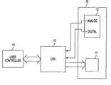
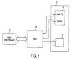
- FIG. 1is a schematic block diagram of an electronic engine control system according to one embodiment of the present invention.
- FIG. 2is a schematic block diagram of an engine control unit according to one embodiment of the present invention.
- FIG. 3is a flow chart of a method for controlling an engine according to one embodiment of the present invention.
- FIG. 4is a flow chart of an input capture routine according to one embodiment of the present invention.
- FIG. 5is a flow chart of an output compare routine according to one embodiment of the present invention.
- FIG. 6is a flow chart of a method for adjusting an engine control relationship according to one embodiment of the present invention.
- FIG. 7shows an exemplary graphical user interface used to select a control relationship in conjunction with the method of FIG. 6 .
- FIG. 8shows an exemplary graphical user interface used to display and adjust the fuel map.
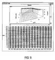
- FIG. 9shows an exemplary graphical user interface used to display and adjust the spark table.
- FIG. 10shows an exemplary graphical user interface used to display and adjust the idle air control relationship.
- FIG. 11shows an exemplary graphical user interface used to display and adjust the nitrous oxide control relationship.
- FIG. 12shows an exemplary graphical user interface used to display and adjust various closed loop parameters.
- FIG. 13shows an exemplary graphical user interface used to display and adjust various hardware parameters.
- a method and system for controlling an engineis disclosed.
- the present inventionadvantageously permits a user to modify the defined relationships that are used to control the engine.
- the method and system of the present inventionenable those control relationships to be adjusted on-the-fly without interrupting the control operation in contrast to conventional engine control units.
- FIG. 1illustrates an engine control system in accordance with one embodiment of the invention.
- the engine control system of FIG. 1comprises an internal combustion engine 10 , an engine control unit 13 and a user controller 14 .
- Internal combustion engine 10comprises a number of control mechanisms 11 that are responsive to control signals developed by engine control unit (ECU) 13 , and a number of sensors 12 that develop analog and digital signals for use by ECU 13 .
- ECUengine control unit
- ECU 13is shown and will be explained in more detail in conjunction with FIG. 2 . Briefly, ECU 13 receives analog and digital input signals from sensors 12 and in response provides control signals to control mechanisms 11 . ECU develops these control signals based on a set of predefined relationships that are stored therein. According to one embodiment, ECU 13 communicates with user controller 14 .
- User controller 14communicates with and is operative to reprogram ECU 13 .
- user controller 14comprises a personal computer that communicates with ECU through a standard modem.
- user controller 14comprises a laptop computer including a display screen to view engine control relationships (for example, tables of control variables) and a keyboard and mouse that is used to modify those control relationships.
- FIG. 2depicts ECU 13 in more detail.
- ECU 13comprises micro-controller 20 , nonvolatile memory 21 , flash memory 22 , and serial communications port 23 .
- ECU 23is responsive to a number of sensors that produce analog inputs and a number of digital inputs.
- the analog inputsinclude inputs from throttle position sensor 240 (indicates the degree of rotation of the engine throttle under control of the operator), exhaust gas oxygen sensor 241 (positioned in the engine exhaust and is used to determine the richness and leanness of the air/fuel mixture entering the cylinders), manifold absolute pressure sensor 242 (indicates air pressure within the engine air intake manifold, which is indicative of engine load), slew fuel input 243 (enables rapid user control of the fuel supply to determine what effect more/less fuel has on engine operation at a given load/RPM point), manifold air temperature sensor 244 , slew spark input 245 (enables rapid user control of the spark timing to determine what effect more/less spark has on engine operation at a given load/RPM point), engine coolant temperature sensor 246 and battery voltage input 247 (reduced voltage input to micro-controller 20 that is indicative of battery voltage —e.g. a 4.8 V input represents 16 V at the battery).
- Each of these sensorsmay comprise appropriate conventional sensors.
- the digital inputsinclude a park/neutral signal 250 (indicates current drive status of vehicle to prevent engine from being started in gear), vehicle speed signal 251 (determines vehicle speed based on drive shaft rotation), ac compressor request signal 252 (indicates ac compressor is on and therefore engine load has increased), REF/PIP signal 253 (signal from OE distributor module indicates spark reference and provides system trigger for GMs and Fords respectively), NOS enable signal 254 (indicates the Nitrous oxide enrichment has been selected), IPU input 255 (magnetic input to be used as a spark reference for crank trigger wheel configurations), knock input 256 (output from a knock sensor), coil input 257 (input from ignition coil primary used as an alternate system trigger to REF/PIP and IPU), switched power input 258 (input indicating that the key to the engine has been turned on) and mode select input 259 (signal indicating whether micro-controller 20 should operate in normal mode or programmed mode).
- a park/neutral signal 250indicates current drive
- ECU 13In response to these analog and digital inputs, ECU 13 produces a number of control signals. Specifically, ECU 13 produces a stepper motor driver signal 260 (used to control the idle air stepper motor (IAC) coupled to the manifold air bypass of engine for adjusting idle speed); fuel injector driver signals 261 (pulsed signals of controlled time duration used to control a plurality of fuel injectors for injecting desired quantities of fuel to the air manifold adjacent to the cylinder intake ports of the engine); electronic ignition control signal 262 (used to control spark timing of the engine); bypass/aux control signal 263 (in aux mode may be used, e.g., for controlling a plurality of LEDs on an operator console or panel to indicate any fault or warning conditions to the operator; in bypass mode may be used to control the function of certain ignition modules, e.g., GM ignition modules); fuel pump control signal 264 (used to control a fuel pump to feed fuel from a tank or supply (not shown) to the injectors of engine); cooling fan control signal 265 (used to
- Microcontroller 20receives the various analog inputs ( 240 - 247 ) and digital inputs ( 250 - 259 ) and generates the control signals ( 260 - 267 ) using control relationships stored in nonvolatile memory 21 .
- microcontroller 20comprises any suitable microprocessor based controller.
- microcontroller 20comprises a Motorola HC68HC11 microprocessor. Other microprocessors are possible.
- the present inventioncomprises two separate memories.
- Nonvolatile memory 21is used to store the control relationships that are used to develop control signals in conjunction with the various analog and digital inputs.
- Flash memory 22is used to store the executable code for microcontroller 20 .
- Nonvolatile memory 21employs a two tier memory structure that comprises a working storage area and a non-volatile storage area.
- the working storage areacomprises a read/write memory that is used to store the control relationships during engine operation.
- the working storage areacomprises memory that can be written and rewritten in real-time so that control operation is not interrupted even while the control relationships are being modified.
- working storage areacomprises RAM.
- the non-volatile storage areacomprises memory that stores the control relationships when power is lost to microcontroller 20 .
- the non-volatile storage areacomprises EEPROM.
- both working storage area and non-volatile storage areacomprise a single non-volatile static RAM chip. Such a chip comprises both RAM and a backup non-volatile EEPROM for storing information when power is lost.
- Flash memory 22comprises a memory that is used to store the executable code for microcontroller 20 .
- the memory holding the executable codetypically some type of ROM, had to be swapped with a memory having the new executable code “burned in.”
- flash memory 22comprises a writeable, non-volatile memory.
- flash memory 22comprises a flash EPROM.
- Serial communications port 23enables microcontroller 20 to communicate with other devices.
- user controller 14communicates with microcontroller 20 through serial communications port 23 .
- serial communications port 23is the communications port through which the control relationships and executable code for microcontroller 20 are rewritten.
- serial communications port 23enables communication of microcontroller 20 with a remote device through a modem.
- serial communications port 23comprises an RS 232 communications port.
- FIGS. 3, 4 , and 5depict flowcharts showing a method of controlling an engine according to one embodiment of the present invention.
- the method of controlling an enginecomprises one or more computer programs that control an engine control unit such as ECU 13 and specifically microcontroller 20 .
- FIG. 3is a flowchart of the main program
- FIG. 4is a flowchart for an input capture routine
- FIG. 5is a flowchart for an output compare routine.
- the method of FIG. 3begins in step 31 by monitoring ECU 13 to determine if the ECU is operating properly.
- the methodcomprises a safety mechanism that will reset the ECU (and the engine) if it is not operating properly.
- the safety mechanismcomprises a software module that determines whether or not a set of instructions has been received. If the set of instructions has been received, it is determined that the ECU is operating properly and there is no need to shut the engine down. If the instructions are not received, it is determined that the engine is not operating properly and the ECU is reset and the engine is shut down.
- the methodaccomplishes a number of polled real-time chores.
- the polled real time chorescomprise a set of operations that are accomplished at regular intervals.
- the program depicted in FIG. 3comprises real-time chores that are accomplished at 4, 8, 16, 32, and 64 ms. Other intervals are possible.
- the polled real-time chores at each intervalcomprise separate subroutines.
- the following chorescomprise real-time polled chores. Other chores may be added.
- the chores outlined belowmay also be moved into any of the other routines, e.g., the main program or the routines of FIGS. 4 and 5.
- readings from throttle position sensor 240 , exhaust gas oxygen sensor 241 , manifold absolute pressure sensor 242 , slew fuel sensor 243 , manifold air temperature sensor 244 , slew spark sensor 245 , engine coolant temperature sensor 246 and battery voltage sensor 247are checked, and their values are converted from analog values to digital values in real-time at step 32 .
- the running countercomprises a counter that is used to determine whether or not the engine being controlled is operating properly.
- the running counteris monitored and incremented during the regular intervals in the main program and cleared during the input capture routine (explained in conjunction with FIG. 4 below). Therefore, if the running counter rises above a particular value it provides an indication that the input capture routine (that is initiated based on crankshaft rotation) has not been initiated and accordingly, that the engine has stopped.
- the running countercomprises a software module that is monitored and incremented at regular intervals. According to this embodiment, if the running counter has reached a value of 128 , it is an indication that the engine is not running properly, and engine control unit 13 is reset.
- the idle air control IAC stepper motoris adjusted as one of the real-time chores.
- the IAC stepper motor 260is part of a PID control loop (see step 44 of FIG. 4) that maintains engine idle speed at a programmed RPM level. Specifically, engine speed and the rate and direction of change of engine speed are monitored and adjustments to IAC stepper motor position are made to either increase or decrease bypass air flow to and thus to increase or decrease engine idle speed, respectively.
- the rate of change of throttle positionis calculated as one of the real-time chores.
- the rate of change in throttle positionis used to determine whether or not transient fueling is necessary.
- fuelis delivered once per crankshaft revolution. Injector pulses are synchronous with the trigger input from the engine tachometer. If the throttle is opened abruptly, synchronous fuel delivery is typically insufficient, and the engine may hesitate or backfire. To overcome this problem, additional fuel pulses are delivered between the synchronous pulses. This is termed asynchronous fueling in the art because the additional fuel is not synchronized with the tachometer signal.
- asynchronous fuelWhen the engine is cold, transient response is greatly improved by the addition of asynchronous fuel, while at hotter engine temperatures asynchronous fuel tends to over fuel the engine.
- a defined relationship between the rate of change of throttle position and engine coolant temperatureis used to determine whether or not asynchronous fueling is appropriate.
- the rate of change of manifold pressureis a real-time chore and is used to determine whether or not transient fueling is required.
- a defined relationship between the rate of change of manifold pressure and engine coolant temperatureis used to determine whether or not synchronous fueling is appropriate.
- the knock signal 256is also monitored. As shown in FIG. 2, the knock sensor comprises a separate digital input to the ECU. According to one embodiment, each time a knock is detected, a programed amount of timing is removed.
- a number of control parametersare looked up as real-time chores. According to one embodiment, these control parameters are based on the current operating conditions of the engine.
- One example of a control parameter that is looked up as a part of the real-time choresis the park position for the IAC stepper motor.
- x-axis pointersare calculated for the control matrices.
- defined relationshipsare used in conjunction with sensor readings to control engine performance. For example, in conjunction with the system shown in FIGS. 1 and 2, for every possible reading of manifold absolute pressure sensor 244 and vehicle speed sensor 251 , micro-controller 20 provides a particular control signal to fuel injector drivers 261 . The same is true for the other sensors and control mechanisms shown in FIG. 2 . These relationships between the sensor readings and the control signals can be expressed in a number of different ways including in a matrix of numbers, and in a graph. In either case, it may be desirable to view the relationship in more detail in a particular area.
- x-axis pointers for the relationshipmay be set.
- x-axis pointersmay be set for each control relationship.
- x-axis pointersmay be set for the fuel map (used to control fuel injector drivers 261 ) and the spark map (used to control electronic ignition controller 262 ).
- the spark advanceis calculated.
- the spark advanceis calculated using a defined relationship (as explained above) based on the RPM reading from vehicle speed sensor 251 and a load reading.
- the load readingmay comprise either a reading from manifold absolute pressure sensor 242 , or throttle position sensor 240 . These two factors, determine a spark advance from the defined relationship.
- cooling fan 265is controlled. According to one embodiment, cooling fan 265 is controlled using a defined relationship based on present readings from engine temperature sensor 246 . According to one embodiment, if the engine temperature is greater than a certain threshold, the cooling fan is activated.
- step 36fuel pump 264 is controlled.
- fuel pump 264remains on, as long as the engine is cranking.
- the running counter(as explained above) is monitored to determine whether or not the engine is cranking. If the running counter is less than a predetermined number, the engine is cranking, and the fuel pump remains activated. According to another embodiment, if the engine continues to crank for more than some predetermined amount of time, the fuel pump is turned off. According to a specific embodiment, if the engine continues to crank for more than 10 seconds, the fuel pump is turned off.
- the injector opening timeis corrected based on a defined relationship.
- the opening time for fuel injectorsmay vary based on the battery voltage. Therefore, in step 37 , the injector opening time is controlled based on the battery voltage.
- the present inventionuses a number of defined relationships in conjunction with sensor readings to control engine performance.
- the battery voltageis determined from battery voltage sensor 247 , and the particular injector opening time that is appropriate for that battery voltage is determined in step 37 and used to control fuel injector drivers 261 .
- a correction factor for injector opening timeis determined based on the battery voltage and used to control fuel injector drivers 261 .
- an engine control unitcommunicates with a programmer to adjust engine control relationships.
- the method of FIG. 3operates in conjunction with ECU 13 shown in FIGS. 1 and 2.
- control parametersare read from and written to non-volatile static memory 22 .
- datais moved in and out of memory 22 in blocks.
- step 39a determination is made whether the engine is running in crank mode or run mode. Depending on whether the engine is operating in run or crank mode, a different set of operations is accomplished. According to one embodiment, it is determined that the engine is operating in run mode if it has been operating at greater than 350 rpm for a predetermined number of cycles. According to a specific embodiment, the reading from engine speed sensor 251 is used to determine whether the engine is operating in run or crank mode. If in step 39 , it is determined that the engine is operating in run mode, operations 310 to 313 are accomplished. If in step 39 it is determined that the engine is operating in crank mode, operations 314 to 318 are accomplished.
- step 310the O 2 subroutine is accomplished.
- the O 2 sensoris checked to determine whether or not the air fuel mixture needs adjustment.
- a PI control loopis used to make the necessary adjustments based on a defined relationship between engine speed and load. Such adjustments are known in the art.
- the nitrous oxide subroutineis called.
- the nitrous oxide subroutinemonitors the nitrous enable line 254 shown in FIG. 2, to determine whether or not nitrous oxide is to be added to the fuel mixture. If the status of nitrous enable line 254 indicates the nitrous oxide is to be added to the fuel mixture, and minimum throttle position, time and RPM thresholds have been met, it is determined that it is appropriate to add nitrous. If nitrous is added, appropriate adjustments to fuel and timing are made based on the RPM reading of vehicle speed sensor 251 and a defined relationship.
- step 312after start subroutine is accomplished.
- After start enrichmentis intended to help overcome the initial start-up frictions and viscosities present in a cold engine, as well as to compensate for hot soak fuel vaporization in the fuel system of hot engines.
- the after start subroutineis used to add additional fuel to the engine in the time period following ignition.
- a counteris maintained to determine whether or not after start enrichment is appropriate.
- the after start counteris incremented in the input capture subroutine shown in FIG. 4 and thus provides an indication of the number of crankshaft revolutions that have occurred.
- an appropriate amount of fuel to be addedis determined based on a reading of engine speed sensor 251 and a defined relationship.
- the additional fuel to be addedis gradually decayed based on a defined relationship between the engine coolant temperature and the counter.
- step 313the fuel injector pulse width subroutine is accomplished. Based on a defined relationship between the manifold absolute pressure and engine speed, the fuel injector pulse width is adjusted. According to one embodiment, a look up table is used to store fuel injector pulse width. According to one specific embodiment, manifold absolute pressure sensor 244 and vehicle speed sensor 251 are read and used to determine the appropriate fuel injector pulse width under run conditions.
- an O 2 delayis determined.
- the O 2 delayis determined based on initial coolant temperature and a defined relationship. As explained previously, the present invention uses a number of defined relationships in conjunction with sensor readings to control engine performance. According to one embodiment, O 2 delay is determined based on readings from engine coolant temperature sensor 246 .
- the park position for IAC stepper motoris determined.
- the park positionis determined based on initial coolant temperature and a defined relationship.
- the present inventionuses a number of defined relationships in conjunction with sensor readings to control engine performance.
- the park positionis determined based on readings from engine coolant temperature sensor 246 .
- step 316it is determined whether or not a flood has occurred. If a flood has occurred in step 317 , injector pulsing is stopped. According to one embodiment, readings from throttle position sensor 240 are used to determine whether or not a flood has occurred. If throttle position exceeds a certain threshold, it is determined a flood has occurred and a clear flood mode is initiated. In the clear flood mode, among other things, injector pulsing is stopped.
- the crank pulse width for the fuel injectoris determined.
- the crank pulse width for the fuel injectorsis determined based on a predefined relationship with engine coolant temperature.
- a look up tableis used to store fuel injector pulse width under cranking conditions.
- engine coolant temperature sensor 246is read and used to determine the appropriate fuel injector pulse width.
- FIG. 4is a flow chart showing a method of capturing input for a subroutine of the main program for controlling ECU 13 shown in FIGS. 1 and 2.
- the input capture method shown in FIG. 4is initiated based on crankshaft rotation. According to one embodiment, the method of FIG. 4 is initiated after the crankshaft rotates 90°. Other embodiments are possible.
- the input capture method of FIG. 4begins with Step 41 where the spark output configuration is determined.
- the spark output configurationdepends on the type of engine that is being controlled.
- the engine control unit shown in FIG. 2may be used to control a number of different engines.
- ECU 13is used to control an engine with an inductive pickup ignition.
- ECU 13is used to control other engine types.
- step 42the end of dwell (EOD) is calculated.
- the end of dwellis calculated in a manner that is known in the art.
- the start of dwell (SOD)is calculated in the output interrupt subroutine shown in FIG. 5 .
- step 43the injectors are fired.
- the manner in which the injectors are fireddepends on, at least, the mode of operation of ECU 13 and the number of cylinders.
- the ECUmay operate in conjunction with a port fuel injection system or a throttle body fuel injection system and in conjunction with engines having any number of cylinders.
- a different set of signalsare generated by microcontroller 20 and are used to control fuel injector drivers 261 .
- step 44idle air stepper motor is controlled.
- the IAC stepper motoris used to control the amount of air in the fuel air mixture and thus control the idle speed.
- a PID (proportional integral differential) calculationis used to determine the IAC control.
- the PID calculationis based on the difference between the desired and actual idle speed (as measured by vehicle speed sensor 251 ).
- Step 45the determination is made as to whether the engine is operating in crank mode or run mode. According to one embodiment, if the engine is operating at greater than 350 RPMs for more than a predetermined number of cycles, the engine is operating in run mode. Otherwise, it is determined that the engine is operating in crank mode.
- Step 46the running counter is cleared.
- the running counterholds a count that is used to determine whether the engine and the ECU are operating properly. Operation of the input capture subroutine indicates that the engine and the ECU are operating properly.
- the running counteris cleared.
- the running countercomprises a software module that is incremented every four milliseconds.
- Step 47the after start counter is incremented.
- the after start countersare used to determine whether or not the engine is operating in an after start mode. For a period of time after an engine is started a richer fuel air mixture is used. The after start counter begins at zero and is incremented each time through the input capture subroutine. When the input counter reaches a certain threshold, it is determined that the richer fuel air mixture is no longer necessary. That is, the engine is no longer operating in an after start mode.
- FIG. 5shows a flowchart depicting an output compare subroutine.
- the output compare subroutineis initiated after each input capture subroutine.
- Other embodimentsare possible.
- the input capture subroutine shown in FIG. 4is used to develop inputs that are used in the output compare subroutine of FIG. 5 .
- the output compare subroutine shown in FIG. 5begins at step 51 by determining the type of ignition system that is being used.
- the ECUmay be used in conjunction with a number of different engine configurations and ignition systems. Each different configuration generally requires a different form of output.
- the outputis configured for the proper ignition system.
- the ECUis used in conjunction with an inductive pickup ignition system.
- Step 52the start of dwell (SOD) is determined.
- the start of dwellis determined using the inputs developed in the input capture subroutine shown in FIG. 4 .
- the start of dwellis determined in a manner that is known in the art.
- FIG. 6is a flowchart showing a method for adjusting engine control relationships according to another embodiment of the present invention.
- the engine control relationshipsare adjusted by a user through a personal computer. The method will be explained in conjunction with the method and system shown in FIGS. 1-5. In that system, as explained above, user controller 14 is provided to accomplish modification of the control relationships.
- a number of engine parametersare set.
- the method and system of the present inventionis useful in conjunction with a number of different engine types that have different specifications. According to one embodiment, these specifications such as the number of cylinders, and whether the engine uses throttle body fuel injection or port fuel injection are selected before control begins.
- the methodbegins in step 61 with selection of a control parameter for adjustment.
- a usermay select any of a plurality of control relationships for adjustment. These control relationships are generally known in the art and are explained briefly below.
- the fuel relationshipcontrols the injector pulse width under run conditions based on manifold absolute pressure and engine speed. According to one embodiment, this relationship is utilized at step 313 of the control method shown in FIG. 3 .
- the spark relationshipcontrols the spark timing based on engine speed and engine load.
- Engine loadmay be measured by manifold absolute pressure or by throttle position.
- the spark relationshipis utilized at step 34 .
- the idle speed relationshipcontrols the speed of the idle through control of IAC stepper motor and depends on engine coolant temperature. According to one embodiment, the idle speed relationship is utilized in step 44 of FIG. 4 .
- the idle park position relationshipcontrols the position in which the idle is parked and depends on engine coolant temperature. According to one embodiment, the idle park position relationship is utilized in step 315 of FIG. 3 .
- the throttle follower relationshipallows a user to monitor the throttle position and idle bypass air of the engine, and to set the minimum limit of the bypass air.
- the purpose of the throttle follower relationshipis to back the idle control mechanism away from its stop at the fully closed position, thereby leaking more air into the intake manifold at off-idle speeds to keep it from smothering the engine during rapid deceleration.
- acceleration enrichment relationshipscontrol whether or not additional fuel should be added during acceleration condition.
- acceleration enrichmentis expressed as additional pulse width to be added to both synchronous or asynchronous pulse widths resulting from the base fuel relationship.
- Acceleration enrichment relationshipsdepend on: 1) the rate of change of the throttle position; 2) coolant temperature; 3) the throttle position 4) the rate of change of manifold absolute pressure, 5) a decay rate factor and 6) manifold pressure acceleration compensation as a function of coolant temperature.
- the after start enrichment relationshipcontrols the amount of after start fuel to be added to the engine and depends on coolant temperature.
- the after start enrichment relationshiprelates percent enrichment to engine coolant temperature.
- the enrichment percentageis added to the base pulse width from the base fuel map.
- the after start hold off relationshipcontrols when after start enrichment should begin and depends on the number of engine revolutions (as measured using, e.g., an after start counter) and engine coolant temperature.
- the amount of enrichmentdecays at a rate specified in an after start enrichment decay relationship.
- the after start enrichment decay relationshipcontrols the rate at which fuel enrichment is to be diminished and depends on engine coolant temperature and the number of revolutions that have occurred.
- the after start relationshipsare utilized in step 312 of FIG. 3 .
- the warm-up enrichment relationshipcontrols whether or not fuel is to be added synchronously while the engine is warming up and depends on engine coolant temperature.
- the relationshipdetermines an enrichment factor that increases the fuel delivered to the engine during warm-up based on engine coolant temperature.
- the air temperature enrichment relationshipcontrols whether or not fuel is to be added synchronously and depends on air temperature into the engine. According to one embodiment, the reading of manifold air temperature sensor 244 is utilized to determine whether or not air temperature enrichment is appropriate.
- cranking pulse width relationshipcontrols the fuel injector pulse width under cranking conditions.
- the injector pulse width under cranking conditionsdepends on engine coolant temperature. According to one embodiment, this relationship is utilized at step 318 of the control method shown in FIG. 3 .
- a graphical user interfaceis provided to enable the user to select a particular control relationship to modify.
- the GUImay provide any of a number of known mechanisms such as text boxes and dialog boxes to enable a user to select or enter a particular control relationship to be adjusted.
- An exemplary GUI that may be used to select a control relationship to modifyis shown in FIG. 7 .
- FIG. 7depicts a selection GUI 71 .
- Selection GUI 71comprises a number of pull down menus 74 that may be used to select various ones of the control relationships for displaying and adjusting.
- control relationshipis accessed.
- the method for adjusting the control relationshipoperates in conjunction with the system of FIGS. 1 and 2 and user controller 14 communicates with engine control unit 13 , using a modem and serial communication port 23 , to access the selected control relationship.
- control relationshipsare stored in nonvolatile static memory 21 .
- nonvolatile static memory 21advantageously enables transfer of data in and out in blocks such that the control relationship may be quickly downloaded to user controller 14 over a modem.
- control relationshipis displayed to the user.
- the control relationshipsvary in complexity. Some, such as the fuel relationship comprise a look-up table that is addressed using the appropriate parameters (manifold absolute pressure and engine speed in the case of the fuel relationship). According to another embodiment, a two-dimensional look-up table may be depicted as a three dimensional map. Other control relationships may comprise a one dimensional relationship or a single value. According to one embodiment, user controller 14 is used to display the control relationship as a table and/or a graph and/or a parameter as appropriate.
- FIG. 8shows the fuel relationship 81 as a matrix or map of numbers 82 .
- This fuel map displaycomprises a display window having a matrix of numeric parameters that form the ECU's base fuel map. The rows correspond to manifold absolute pressure and the columns to engine speed in RPM.
- FIG. 8also shows the fuel relationship as a three dimensional graph 83 .
- the three dimensional plot of the base fuel mapis useful for identifying severe discontinuities or irregularities in the base fuel map that may otherwise go unnoticed in the numeric table.
- the display of other relationshipsis similar to the display of the fuel relationship.
- FIGS. 9-13show GUIs that are used to control other exemplary relationships such as the spark table (FIG. 9 ), IAC (FIG. 10 ), nitrous oxide boost (FIG. 11 ), closed loop parameters (FIG. 12 ), and hardware parameters (FIG. 13 ).
- the selected control relationshipis adjusted.
- a mouseis used to select one of the values in the map in a manner that is known in the art. Once the value is selected, the up and down arrow keys on a keyboard may be used to adjust the value. Alternatively, the user may simply type a new value over the existing value.
- a mouseis used to select and hold a point on the graph. Once selected the point on the graph may be physically raised or lowered using the mouse. Alternatively, once the point on the map is selected, the up and down arrow keys on a keyboard may be used to adjust the value. Other methods of adjusting a value are possible.
- steps 65the adjustments are rewritten to memory in the controller and are available for use by the controller in real-time.
- a useruses the mouse or keyboard arrows to adjust a control relationship
- that adjustmentis immediately communicated to the engine control unit and written over the existing control relationship.
- those adjustmentsare advantageously made available for use by the controller in real-time without any control disabling in contrast to conventional control schemes.
- thisis made possible by the provision of nonvolatile static memory 21 shown in FIG. 2 . The end result is that the effect of the adjustments are felt in real time in the vehicle.
Landscapes
- Engineering & Computer Science (AREA)
- Chemical & Material Sciences (AREA)
- Combustion & Propulsion (AREA)
- Mechanical Engineering (AREA)
- General Engineering & Computer Science (AREA)
- Computer Hardware Design (AREA)
- Microelectronics & Electronic Packaging (AREA)
- Electrical Control Of Air Or Fuel Supplied To Internal-Combustion Engine (AREA)
- Combined Controls Of Internal Combustion Engines (AREA)
Abstract
Description
Claims (11)
Priority Applications (1)
| Application Number | Priority Date | Filing Date | Title |
|---|---|---|---|
| US09/699,407US6535811B1 (en) | 1999-11-03 | 2000-10-31 | System and method for real-time electronic engine control |
Applications Claiming Priority (2)
| Application Number | Priority Date | Filing Date | Title |
|---|---|---|---|
| US16325399P | 1999-11-03 | 1999-11-03 | |
| US09/699,407US6535811B1 (en) | 1999-11-03 | 2000-10-31 | System and method for real-time electronic engine control |
Publications (1)
| Publication Number | Publication Date |
|---|---|
| US6535811B1true US6535811B1 (en) | 2003-03-18 |
Family
ID=26859484
Family Applications (1)
| Application Number | Title | Priority Date | Filing Date |
|---|---|---|---|
| US09/699,407Expired - LifetimeUS6535811B1 (en) | 1999-11-03 | 2000-10-31 | System and method for real-time electronic engine control |
Country Status (1)
| Country | Link |
|---|---|
| US (1) | US6535811B1 (en) |
Cited By (37)
| Publication number | Priority date | Publication date | Assignee | Title |
|---|---|---|---|---|
| US20020073400A1 (en)* | 2000-07-26 | 2002-06-13 | Michael Beuten | Method for monitoring a program execution using a debug logic |
| US20030097521A1 (en)* | 2000-03-22 | 2003-05-22 | Martin Pfandler | Method for reprogramming a field device |
| US6604027B1 (en)* | 2002-07-24 | 2003-08-05 | Mitsubishi Denki Kabushiki Kaisha | Electronic control apparatus for vehicle |
| US20040094134A1 (en)* | 2002-06-25 | 2004-05-20 | Redmond Scott D. | Methods and apparatus for converting internal combustion engine (ICE) vehicles to hydrogen fuel |
| US20040117106A1 (en)* | 2002-12-12 | 2004-06-17 | Frank Dudel | Chipped engine control unit system having copy protected and selectable multiple control programs |
| US20040158422A1 (en)* | 2002-05-02 | 2004-08-12 | Brown David R. | Fault tolerant apparatus and method for determining a revolution rate of a gear |
| US6799101B2 (en)* | 2002-12-05 | 2004-09-28 | Wabco Gmbh & Co. Ohg | Method for programming flash EEPROMS in microprocessor-equipped vehicle control electronics |
| US20040249558A1 (en)* | 2003-06-06 | 2004-12-09 | John Meaney | System and method for real time programmability of an engine control unit |
| US20060063642A1 (en)* | 2004-09-20 | 2006-03-23 | Detroit Diesel Corporation | System and method for controlling engine idle speed based on operational state settings |
| US20060117131A1 (en)* | 2002-11-07 | 2006-06-01 | Klaus Schneider | Method for the secure checking of a memory region of a microcontroller in a control device and control devide with a protected microcontroller |
| US20060151670A1 (en)* | 2004-02-10 | 2006-07-13 | Loss Kevin L | Methods and systems for controlling flammability control systems in aircraft and other vehicles |
| US20070028898A1 (en)* | 2005-08-05 | 2007-02-08 | Keihin Corporation | Electronic fuel injection control device |
| FR2892466A1 (en)* | 2005-10-25 | 2007-04-27 | Renault Sas | ELECTRONIC CONTROL UNIT FOR A VEHICLE ENGINE HAVING AT LEAST ONE IMPROVED CONTROL LAW |
| US20070199545A1 (en)* | 2005-12-31 | 2007-08-30 | Mcgee Brian G | Fuel system having variable waveform based on operator objective |
| US20110166769A1 (en)* | 2010-01-07 | 2011-07-07 | Jeffrey Douglas Buechler | Supplemental Vapor Fuel Injection System for Internal Combustion Engines |
| US20110275321A1 (en)* | 2008-10-31 | 2011-11-10 | Xuesong Zhou | Integrated Vehicle Key and Mobile Phone System for Preventing Mobile Phone Use While Driving |
| US20120133319A1 (en)* | 2008-10-23 | 2012-05-31 | Won-Door Corporation | Methods, systems, and devices for a motor control system |
| CN102943709A (en)* | 2012-10-31 | 2013-02-27 | 深圳市元征科技股份有限公司 | Multifunctional engine control unit |
| US20130158838A1 (en)* | 2011-12-15 | 2013-06-20 | Ego-Gear, Llc | Device to Increase Fuel Economy |
| US20130173137A1 (en)* | 2011-12-29 | 2013-07-04 | General Electric Company | System, apparatus, and method for protecting vehicle engines |
| US20130261942A1 (en)* | 2012-04-01 | 2013-10-03 | Zonar Systems, Inc. | Method and apparatus for matching vehicle ecu programming to current vehicle operating conditions |
| US20130332024A1 (en)* | 2012-06-08 | 2013-12-12 | Airbiquity Inc. | Assessment of electronic sensor data to remotely identify a motor vehicle and monitor driver behavior |
| US20140288808A1 (en)* | 2013-03-20 | 2014-09-25 | Ford Global Technologies, Llc | Automatic engine de-choking |
| US8942888B2 (en) | 2009-10-15 | 2015-01-27 | Airbiquity Inc. | Extensible scheme for operating vehicle head unit as extended interface for mobile device |
| US8971927B2 (en) | 2008-10-09 | 2015-03-03 | Xuesong Zhou | System and method for preventing cell phone use while driving |
| US9002574B2 (en) | 2009-10-15 | 2015-04-07 | Airbiquity Inc. | Mobile integration platform (MIP) integrated handset application proxy (HAP) |
| RU2577690C2 (en)* | 2012-04-19 | 2016-03-20 | ФОРД ГЛОУБАЛ ТЕКНОЛОДЖИЗ, ЭлЭлСи | Methods for engine and fuel system and vehicle system |
| US9370029B2 (en) | 2009-10-15 | 2016-06-14 | Airbiquity Inc. | Efficient headunit communication integration |
| US9689336B2 (en) | 2014-11-10 | 2017-06-27 | Caterpillar Inc. | Engine system utilizing modal weighted engine optimization |
| USD800739S1 (en) | 2016-02-16 | 2017-10-24 | General Electric Company | Display screen with graphical user interface for displaying test details of an engine control test |
| US10012197B2 (en) | 2013-10-18 | 2018-07-03 | Holley Performance Products, Inc. | Fuel injection throttle body |
| US10056008B1 (en) | 2006-06-20 | 2018-08-21 | Zonar Systems, Inc. | Using telematics data including position data and vehicle analytics to train drivers to improve efficiency of vehicle use |
| US10495014B2 (en) | 2011-12-29 | 2019-12-03 | Ge Global Sourcing Llc | Systems and methods for displaying test details of an engine control test |
| US10800418B2 (en) | 2018-08-31 | 2020-10-13 | Powerteq Llc | Systems, methods, and apparatuses for controlling engine operations |
| US10906482B2 (en) | 2016-05-26 | 2021-02-02 | Powerteq Llc | Real-time performance tuning |
| US10961944B2 (en)* | 2015-06-24 | 2021-03-30 | Hitachi Automotive Systems, Ltd. | Fuel injection control device |
| US10961968B2 (en) | 2016-01-13 | 2021-03-30 | Fuel Injection Technology Inc. | EFI throttle body with side fuel injectors |
Citations (20)
| Publication number | Priority date | Publication date | Assignee | Title |
|---|---|---|---|---|
| US4182278A (en) | 1977-08-29 | 1980-01-08 | Coakwell Charles A | Combustion system for internal combustion engines |
| US4331121A (en) | 1980-04-17 | 1982-05-25 | Stokes Charlie M | Blending system for unconventional fuels and regular fuel or fuels |
| US4467764A (en) | 1982-04-07 | 1984-08-28 | Nippondenso Co., Ltd. | Method and apparatus for controlling ignition timing in a multicylinder internal combustion engine |
| US4480595A (en) | 1982-01-18 | 1984-11-06 | Hobby William M | Internal combustion engine |
| US4494488A (en) | 1984-05-23 | 1985-01-22 | Ram Automotive Company | Fuel charging system for high performance vehicles |
| US4503823A (en) | 1981-09-18 | 1985-03-12 | Hitachi, Ltd. | Ignition timing control apparatus for internal combustion engine |
| US4572140A (en) | 1984-10-09 | 1986-02-25 | Ram Automotive Company | Nitrous oxide precooler |
| US4683843A (en) | 1986-08-13 | 1987-08-04 | Ram Automotive Company | Nitrous oxide fuel injection safety system |
| US4750453A (en) | 1980-06-30 | 1988-06-14 | Valdespino Joseph M | Internal combustion engine |
| US4798190A (en) | 1986-05-30 | 1989-01-17 | Nitrous Oxide Systems, Inc. | Nozzle |
| US4827888A (en) | 1986-05-30 | 1989-05-09 | Nitrous Oxide Systems, Inc. | Nozzle |
| US4840157A (en) | 1988-05-20 | 1989-06-20 | Furrow Robert E | Engine speed control circuit for drag racing |
| US4960080A (en) | 1989-02-28 | 1990-10-02 | Cummins Engine Company, Inc. | Pollution control apparatus and method for a turbodiesel motor-generator set |
| US5088464A (en) | 1991-06-24 | 1992-02-18 | Echlin, Inc. | Motorcycle engine management system |
| US5091858A (en) | 1989-01-09 | 1992-02-25 | Digital Fuel Injection | Electronic control of engine fuel delivery |
| US5174263A (en) | 1991-06-24 | 1992-12-29 | Echlin, Inc. | Motorcycle engine management system |
| US5287281A (en) | 1991-02-27 | 1994-02-15 | Echlin Inc. | Computer controlled flow of nitrous oxide injected into an internal combustion engine |
| US5341785A (en) | 1992-07-20 | 1994-08-30 | Echlin, Inc. | Fuel delivery system for internal combustion engines |
| US5699776A (en) | 1997-03-06 | 1997-12-23 | Nitrous Express, Inc. | Nozzle for mixing oxidizer with fuel |
| US6009372A (en)* | 1997-10-01 | 1999-12-28 | Cummins Engine Company, Inc. | Management of programming and memory space for an internal combustion engine control system |
- 2000
- 2000-10-31USUS09/699,407patent/US6535811B1/ennot_activeExpired - Lifetime
Patent Citations (21)
| Publication number | Priority date | Publication date | Assignee | Title |
|---|---|---|---|---|
| US4182278A (en) | 1977-08-29 | 1980-01-08 | Coakwell Charles A | Combustion system for internal combustion engines |
| US4331121A (en) | 1980-04-17 | 1982-05-25 | Stokes Charlie M | Blending system for unconventional fuels and regular fuel or fuels |
| US4750453A (en) | 1980-06-30 | 1988-06-14 | Valdespino Joseph M | Internal combustion engine |
| US4503823A (en) | 1981-09-18 | 1985-03-12 | Hitachi, Ltd. | Ignition timing control apparatus for internal combustion engine |
| US4480595A (en) | 1982-01-18 | 1984-11-06 | Hobby William M | Internal combustion engine |
| US4467764A (en) | 1982-04-07 | 1984-08-28 | Nippondenso Co., Ltd. | Method and apparatus for controlling ignition timing in a multicylinder internal combustion engine |
| US4494488A (en) | 1984-05-23 | 1985-01-22 | Ram Automotive Company | Fuel charging system for high performance vehicles |
| US4572140A (en) | 1984-10-09 | 1986-02-25 | Ram Automotive Company | Nitrous oxide precooler |
| US4827888A (en) | 1986-05-30 | 1989-05-09 | Nitrous Oxide Systems, Inc. | Nozzle |
| US4798190A (en) | 1986-05-30 | 1989-01-17 | Nitrous Oxide Systems, Inc. | Nozzle |
| US4683843A (en) | 1986-08-13 | 1987-08-04 | Ram Automotive Company | Nitrous oxide fuel injection safety system |
| US4840157A (en) | 1988-05-20 | 1989-06-20 | Furrow Robert E | Engine speed control circuit for drag racing |
| US5091858A (en) | 1989-01-09 | 1992-02-25 | Digital Fuel Injection | Electronic control of engine fuel delivery |
| US4960080A (en) | 1989-02-28 | 1990-10-02 | Cummins Engine Company, Inc. | Pollution control apparatus and method for a turbodiesel motor-generator set |
| US5287281A (en) | 1991-02-27 | 1994-02-15 | Echlin Inc. | Computer controlled flow of nitrous oxide injected into an internal combustion engine |
| US5444628A (en) | 1991-02-27 | 1995-08-22 | Echlin Inc. | Computer controlled flow of nitrous oxide injected into an internal combustion engine |
| US5088464A (en) | 1991-06-24 | 1992-02-18 | Echlin, Inc. | Motorcycle engine management system |
| US5174263A (en) | 1991-06-24 | 1992-12-29 | Echlin, Inc. | Motorcycle engine management system |
| US5341785A (en) | 1992-07-20 | 1994-08-30 | Echlin, Inc. | Fuel delivery system for internal combustion engines |
| US5699776A (en) | 1997-03-06 | 1997-12-23 | Nitrous Express, Inc. | Nozzle for mixing oxidizer with fuel |
| US6009372A (en)* | 1997-10-01 | 1999-12-28 | Cummins Engine Company, Inc. | Management of programming and memory space for an internal combustion engine control system |
Cited By (68)
| Publication number | Priority date | Publication date | Assignee | Title |
|---|---|---|---|---|
| US20030097521A1 (en)* | 2000-03-22 | 2003-05-22 | Martin Pfandler | Method for reprogramming a field device |
| US7320067B2 (en)* | 2000-03-22 | 2008-01-15 | Endress + Hauser Gmbh + Co. Kg | Method for reprogramming a field device |
| US7712084B2 (en)* | 2000-07-26 | 2010-05-04 | Robert Bosch Gmbh | Method for monitoring a program execution using a debug logic |
| US20020073400A1 (en)* | 2000-07-26 | 2002-06-13 | Michael Beuten | Method for monitoring a program execution using a debug logic |
| US20040158422A1 (en)* | 2002-05-02 | 2004-08-12 | Brown David R. | Fault tolerant apparatus and method for determining a revolution rate of a gear |
| US6823275B2 (en)* | 2002-05-02 | 2004-11-23 | Invensys Systems, Inc. | Fault tolerant apparatus and method for determining a revolution rate of a gear |
| US20040094134A1 (en)* | 2002-06-25 | 2004-05-20 | Redmond Scott D. | Methods and apparatus for converting internal combustion engine (ICE) vehicles to hydrogen fuel |
| US6604027B1 (en)* | 2002-07-24 | 2003-08-05 | Mitsubishi Denki Kabushiki Kaisha | Electronic control apparatus for vehicle |
| US7293148B2 (en)* | 2002-11-07 | 2007-11-06 | Robert Bosch Gmbh | Method for reliably verifying a memory area of a microcontroller in a control unit and control unit having a protected microcontroller |
| US20060117131A1 (en)* | 2002-11-07 | 2006-06-01 | Klaus Schneider | Method for the secure checking of a memory region of a microcontroller in a control device and control devide with a protected microcontroller |
| US6799101B2 (en)* | 2002-12-05 | 2004-09-28 | Wabco Gmbh & Co. Ohg | Method for programming flash EEPROMS in microprocessor-equipped vehicle control electronics |
| US20050086539A1 (en)* | 2002-12-12 | 2005-04-21 | Frank Dudel | Chipped engine control unit system having copy protected and selectable multiple control programs |
| US7047128B2 (en) | 2002-12-12 | 2006-05-16 | Rtk Technologies Limited | Chipped engine control unit system having copy protected and selectable multiple control programs |
| US7236877B2 (en) | 2002-12-12 | 2007-06-26 | Rtk Technologies Limited | Chipped engine control unit system having copy protected and selectable multiple control programs |
| US20040117106A1 (en)* | 2002-12-12 | 2004-06-17 | Frank Dudel | Chipped engine control unit system having copy protected and selectable multiple control programs |
| US6928362B2 (en) | 2003-06-06 | 2005-08-09 | John Meaney | System and method for real time programmability of an engine control unit |
| US20040249558A1 (en)* | 2003-06-06 | 2004-12-09 | John Meaney | System and method for real time programmability of an engine control unit |
| US7191983B2 (en)* | 2004-02-10 | 2007-03-20 | The Boeing Company | Methods and systems for controlling flammability control systems in aircraft and other vehicles |
| US20060151670A1 (en)* | 2004-02-10 | 2006-07-13 | Loss Kevin L | Methods and systems for controlling flammability control systems in aircraft and other vehicles |
| US7104924B2 (en) | 2004-09-20 | 2006-09-12 | Detroit Diesel Corporation | System and method for controlling engine idle speed based on operational state settings |
| US20060063642A1 (en)* | 2004-09-20 | 2006-03-23 | Detroit Diesel Corporation | System and method for controlling engine idle speed based on operational state settings |
| US20070028898A1 (en)* | 2005-08-05 | 2007-02-08 | Keihin Corporation | Electronic fuel injection control device |
| US7905217B2 (en)* | 2005-08-05 | 2011-03-15 | Keihin Corporation | Electronic fuel injection control device |
| FR2892466A1 (en)* | 2005-10-25 | 2007-04-27 | Renault Sas | ELECTRONIC CONTROL UNIT FOR A VEHICLE ENGINE HAVING AT LEAST ONE IMPROVED CONTROL LAW |
| WO2007048972A3 (en)* | 2005-10-25 | 2007-06-14 | Renault Sa | Electronic control unit for a vehicle engine comprising at least one improved control law |
| US20070199545A1 (en)* | 2005-12-31 | 2007-08-30 | Mcgee Brian G | Fuel system having variable waveform based on operator objective |
| US10223935B2 (en) | 2006-06-20 | 2019-03-05 | Zonar Systems, Inc. | Using telematics data including position data and vehicle analytics to train drivers to improve efficiency of vehicle use |
| US10056008B1 (en) | 2006-06-20 | 2018-08-21 | Zonar Systems, Inc. | Using telematics data including position data and vehicle analytics to train drivers to improve efficiency of vehicle use |
| US8971927B2 (en) | 2008-10-09 | 2015-03-03 | Xuesong Zhou | System and method for preventing cell phone use while driving |
| US20120133319A1 (en)* | 2008-10-23 | 2012-05-31 | Won-Door Corporation | Methods, systems, and devices for a motor control system |
| US8368340B2 (en)* | 2008-10-23 | 2013-02-05 | Won-Door Corporation | Methods, systems, and devices for a motor control system |
| US20110275321A1 (en)* | 2008-10-31 | 2011-11-10 | Xuesong Zhou | Integrated Vehicle Key and Mobile Phone System for Preventing Mobile Phone Use While Driving |
| US9002574B2 (en) | 2009-10-15 | 2015-04-07 | Airbiquity Inc. | Mobile integration platform (MIP) integrated handset application proxy (HAP) |
| US9730254B2 (en) | 2009-10-15 | 2017-08-08 | Airbiquity Inc. | Efficient headunit communication integration |
| US9370029B2 (en) | 2009-10-15 | 2016-06-14 | Airbiquity Inc. | Efficient headunit communication integration |
| US10159098B2 (en) | 2009-10-15 | 2018-12-18 | Airbiquity Inc. | Efficient headunit communication integration |
| US8942888B2 (en) | 2009-10-15 | 2015-01-27 | Airbiquity Inc. | Extensible scheme for operating vehicle head unit as extended interface for mobile device |
| US20110166769A1 (en)* | 2010-01-07 | 2011-07-07 | Jeffrey Douglas Buechler | Supplemental Vapor Fuel Injection System for Internal Combustion Engines |
| US20220242386A1 (en)* | 2011-12-15 | 2022-08-04 | Voyomotive, Llc | Device to Increase Fuel Economy |
| US20130158838A1 (en)* | 2011-12-15 | 2013-06-20 | Ego-Gear, Llc | Device to Increase Fuel Economy |
| US10495014B2 (en) | 2011-12-29 | 2019-12-03 | Ge Global Sourcing Llc | Systems and methods for displaying test details of an engine control test |
| US20130173137A1 (en)* | 2011-12-29 | 2013-07-04 | General Electric Company | System, apparatus, and method for protecting vehicle engines |
| US10061745B2 (en)* | 2012-04-01 | 2018-08-28 | Zonar Sytems, Inc. | Method and apparatus for matching vehicle ECU programming to current vehicle operating conditions |
| US10289651B2 (en) | 2012-04-01 | 2019-05-14 | Zonar Systems, Inc. | Method and apparatus for matching vehicle ECU programming to current vehicle operating conditions |
| US20130261942A1 (en)* | 2012-04-01 | 2013-10-03 | Zonar Systems, Inc. | Method and apparatus for matching vehicle ecu programming to current vehicle operating conditions |
| RU2577690C2 (en)* | 2012-04-19 | 2016-03-20 | ФОРД ГЛОУБАЛ ТЕКНОЛОДЖИЗ, ЭлЭлСи | Methods for engine and fuel system and vehicle system |
| US9104538B2 (en)* | 2012-06-08 | 2015-08-11 | Airbiquity Inc. | Assessment of electronic sensor data to remotely identify a motor vehicle and monitor driver behavior |
| US20130332024A1 (en)* | 2012-06-08 | 2013-12-12 | Airbiquity Inc. | Assessment of electronic sensor data to remotely identify a motor vehicle and monitor driver behavior |
| US20150371465A1 (en)* | 2012-06-08 | 2015-12-24 | Airbiquity Inc. | Assessment of electronic sensor data to remotely identify a motor vehicle and monitor driver behavior |
| US9401057B2 (en)* | 2012-06-08 | 2016-07-26 | Airbiquity Inc. | Assessment of electronic sensor data to remotely identify a motor vehicle and monitor driver behavior |
| US11004277B2 (en)* | 2012-06-08 | 2021-05-11 | Airbiquity Inc. | Assessment of electronic sensor data to remotely identify a motor vehicle and monitor driver behavior |
| US20160321844A1 (en)* | 2012-06-08 | 2016-11-03 | Airbiquity Inc. | Assessment of electronic sensor data to remotely identify a motor vehicle and monitor driver behavior |
| CN102943709A (en)* | 2012-10-31 | 2013-02-27 | 深圳市元征科技股份有限公司 | Multifunctional engine control unit |
| CN102943709B (en)* | 2012-10-31 | 2015-05-27 | 深圳市元征科技股份有限公司 | Multifunctional engine control unit |
| US20140288808A1 (en)* | 2013-03-20 | 2014-09-25 | Ford Global Technologies, Llc | Automatic engine de-choking |
| US9347390B2 (en)* | 2013-03-20 | 2016-05-24 | Ford Global Technologies, Llc | Engine de-choking in response to an engine flood event |
| US10012197B2 (en) | 2013-10-18 | 2018-07-03 | Holley Performance Products, Inc. | Fuel injection throttle body |
| US10570866B2 (en) | 2013-10-18 | 2020-02-25 | Holley Performance Products, Inc. | Fuel injection throttle body |
| US11409894B2 (en) | 2013-10-18 | 2022-08-09 | Holley Performance Products, Inc. | Fuel injection throttle body |
| US12203434B2 (en) | 2013-10-18 | 2025-01-21 | Holley Performance Products, Inc. | Fuel injection throttle body |
| US9689336B2 (en) | 2014-11-10 | 2017-06-27 | Caterpillar Inc. | Engine system utilizing modal weighted engine optimization |
| US10961944B2 (en)* | 2015-06-24 | 2021-03-30 | Hitachi Automotive Systems, Ltd. | Fuel injection control device |
| US10961968B2 (en) | 2016-01-13 | 2021-03-30 | Fuel Injection Technology Inc. | EFI throttle body with side fuel injectors |
| US11391255B2 (en) | 2016-01-13 | 2022-07-19 | Fuel Injection Technology Inc. | EFI throttle body with side fuel injectors |
| US12012919B2 (en) | 2016-01-13 | 2024-06-18 | Fuel Injection Technology Inc. | EFI throttle body with side fuel injectors |
| USD800739S1 (en) | 2016-02-16 | 2017-10-24 | General Electric Company | Display screen with graphical user interface for displaying test details of an engine control test |
| US10906482B2 (en) | 2016-05-26 | 2021-02-02 | Powerteq Llc | Real-time performance tuning |
| US10800418B2 (en) | 2018-08-31 | 2020-10-13 | Powerteq Llc | Systems, methods, and apparatuses for controlling engine operations |
Similar Documents
| Publication | Publication Date | Title |
|---|---|---|
| US6535811B1 (en) | System and method for real-time electronic engine control | |
| US5091858A (en) | Electronic control of engine fuel delivery | |
| US6125823A (en) | System and method for controlling fuel injections | |
| US5174263A (en) | Motorcycle engine management system | |
| US20040025849A1 (en) | Injection control for a common rail fuel system | |
| US6516782B1 (en) | System and method for controlling fuel injections | |
| US6439190B1 (en) | Method for operating an internal combustion engine, especially of an automobile | |
| KR100626995B1 (en) | Starting method of internal combustion engine and internal combustion engine for automobile | |
| GB2316197A (en) | A method for maintaining engine speed when starting and idling | |
| KR900002311B1 (en) | Electronic internal combustion engine controller | |
| JPS608340B2 (en) | Fuel injection control device for internal combustion engine | |
| JP2982557B2 (en) | Engine intake air control system | |
| CA2514394C (en) | Fuel injection controller of engine | |
| US5233965A (en) | Fuel injection quantity control system for starting a two-cycle engine | |
| US5092297A (en) | Air-fuel ratio control device for a vehicle engine | |
| JP2884875B2 (en) | Ignition timing control device for resuming fuel supply of internal combustion engine | |
| JPH0771293A (en) | Idle rotational speed control device for internal combustion engine | |
| JPH0615829B2 (en) | Electronically controlled fuel injection device for internal combustion engine | |
| GB2404746A (en) | Controlling multiple fuel injections in a common rail fuel injection system | |
| JPH05149221A (en) | Car engine starter | |
| JPH06221204A (en) | Method and apparatus for starting otto type engine | |
| CA2043205C (en) | Engine start control system | |
| KR19990003448A (en) | Fuel injection method to prevent rapid start and acceleration of vehicle | |
| JPH08121228A (en) | Controller for internal combustion engine | |
| JPS63246442A (en) | Fuel feeding device for engine |
Legal Events
| Date | Code | Title | Description |
|---|---|---|---|
| AS | Assignment | Owner name:FLEET CAPITAL CORPORATION, ILLINOIS Free format text:SECURITY AGREEMENT;ASSIGNOR:HOLLEY PERFORMANCE PRODUCTS, INC;REEL/FRAME:011641/0166 Effective date:20001229 Owner name:FLEET CAPITAL CORPORATION, ILLINOIS Free format text:SECURITY INTEREST;ASSIGNOR:EARL'S SUPPLY COMPANY;REEL/FRAME:011641/0115 Effective date:20001229 | |
| AS | Assignment | Owner name:HOLLEY PERFORMANCE PRODUCTS, INC., KENTUCKY Free format text:ASSIGNMENT OF ASSIGNORS INTEREST;ASSIGNORS:ROWLAND, ZACH L.;CLAIBORNE, JIMMY D.;HEATH, DAVID E.;AND OTHERS;REEL/FRAME:011847/0551;SIGNING DATES FROM 20010227 TO 20010507 | |
| STCF | Information on status: patent grant | Free format text:PATENTED CASE | |
| AS | Assignment | Owner name:ACUSPHERE, INC., MASSACHUSETTS Free format text:TERMINATION OF SECURITY INTEREST;ASSIGNORS:GATX VENTURES, INC.;VENTURE LENDING & LEASING, III;REEL/FRAME:014384/0058 Effective date:20030708 | |
| AS | Assignment | Owner name:U.S. BANK NATIONAL ASSOCIATION, MASSACHUSETTS Free format text:SECURITY AGREEMENT;ASSIGNORS:HOLLEY PERFORMANCE PRODUCTS INC.;HOLLEY PERFORMANCE SYSTEMS, INC.;WEIAND AUTOMOTIVE INDUSTRIES, INC.;AND OTHERS;REEL/FRAME:017105/0764 Effective date:20060126 | |
| FPAY | Fee payment | Year of fee payment:4 | |
| AS | Assignment | Owner name:WELLS FARGO FOOTHILL, INC. (F/K/A FOOTHILL CAPITAL Free format text:SECURITY AGREEMENT;ASSIGNOR:HOLLEY PERFORMANCE PRODUCTS, INC.;REEL/FRAME:019850/0082 Effective date:20020730 | |
| AS | Assignment | Owner name:U.S. BANK NATIONAL ASSOCIATION, MASSACHUSETTS Free format text:SECURITY AGREEMENT;ASSIGNORS:HOLLEY PERFORMANCE PRODUCTS INC.;HOLLEY PERFORMANCE SYSTEMS, INC.;WEIAND AUTOMOTIVE INDUSTRIES, INC.;AND OTHERS;REEL/FRAME:020723/0246 Effective date:20080328 | |
| AS | Assignment | Owner name:WELLS FARGO FOOTHILL, INC., MASSACHUSETTS Free format text:SECURITY AGREEMENT;ASSIGNORS:HOLLEY PERFORMANCE PRODUCTS INC.;HOLLEY PERFORMANCE SYSTEMS, INC.;WEIAND AUTOMOTIVE INDUSTRIES, INC.;AND OTHERS;REEL/FRAME:020741/0193 Effective date:20080328 | |
| AS | Assignment | Owner name:WELL FARGO CAPITAL FINANCE, INC., AS AGENT,CALIFOR Free format text:SECURITY AGREEMENT;ASSIGNOR:HOLLEY PERFORMANCE PRODUCTS INC.;REEL/FRAME:024563/0922 Effective date:20100622 | |
| AS | Assignment | Owner name:HOLLEY PERFORMANCE PRODUCTS INC.,KENTUCKY Free format text:RELEASE OF SECURITY INTEREST RECORDED AT REEL 17105 FRAME 0764;ASSIGNOR:U.S. BANK NATIONAL ASSOCIATION;REEL/FRAME:024599/0236 Effective date:20100622 Owner name:HOLLEY PERFORMANCE SYSTEMS, INC.,KENTUCKY Free format text:RELEASE OF SECURITY INTEREST RECORDED AT REEL 17105 FRAME 0764;ASSIGNOR:U.S. BANK NATIONAL ASSOCIATION;REEL/FRAME:024599/0236 Effective date:20100622 Owner name:WEIAND AUTOMOTIVE INDUSTRIES, INC.,KENTUCKY Free format text:RELEASE OF SECURITY INTEREST RECORDED AT REEL 17105 FRAME 0764;ASSIGNOR:U.S. BANK NATIONAL ASSOCIATION;REEL/FRAME:024599/0236 Effective date:20100622 Owner name:NITROUS OXIDE SYSTEMS, INC.,KENTUCKY Free format text:RELEASE OF SECURITY INTEREST RECORDED AT REEL 17105 FRAME 0764;ASSIGNOR:U.S. BANK NATIONAL ASSOCIATION;REEL/FRAME:024599/0236 Effective date:20100622 Owner name:HOLLEY PERFORMANCE PRODUCTS HOLDINGS, INC.,KENTUCK Free format text:RELEASE OF SECURITY INTEREST RECORDED AT REEL 17105 FRAME 0764;ASSIGNOR:U.S. BANK NATIONAL ASSOCIATION;REEL/FRAME:024599/0236 Effective date:20100622 Owner name:HOLLEY PERFORMANCE PRODUCTS INC.,KENTUCKY Free format text:RELEASE OF SECURITY INTEREST RECORDED AT REEL 20723 FRAME 0246;ASSIGNOR:U.S. BANK NATIONAL ASSOCIATION;REEL/FRAME:024599/0288 Effective date:20100622 Owner name:HOLLEY PERFORMANCE SYSTEMS, INC.,KENTUCKY Free format text:RELEASE OF SECURITY INTEREST RECORDED AT REEL 20723 FRAME 0246;ASSIGNOR:U.S. BANK NATIONAL ASSOCIATION;REEL/FRAME:024599/0288 Effective date:20100622 Owner name:WEIAND AUTOMOTIVE INDUSTRIES, INC.,KENTUCKY Free format text:RELEASE OF SECURITY INTEREST RECORDED AT REEL 20723 FRAME 0246;ASSIGNOR:U.S. BANK NATIONAL ASSOCIATION;REEL/FRAME:024599/0288 Effective date:20100622 Owner name:NITROUS OXIDE SYSTEMS, INC.,KENTUCKY Free format text:RELEASE OF SECURITY INTEREST RECORDED AT REEL 20723 FRAME 0246;ASSIGNOR:U.S. BANK NATIONAL ASSOCIATION;REEL/FRAME:024599/0288 Effective date:20100622 Owner name:HOLLEY PERFORMANCE PRODUCTS HOLDINGS, INC.,KENTUCK Free format text:RELEASE OF SECURITY INTEREST RECORDED AT REEL 20723 FRAME 0246;ASSIGNOR:U.S. BANK NATIONAL ASSOCIATION;REEL/FRAME:024599/0288 Effective date:20100622 | |
| AS | Assignment | Owner name:WILMINGTON TRUST FSB,DELAWARE Free format text:SECURITY AGREEMENT;ASSIGNOR:HOLLEY PERFORMANCE PRODUCTS INC.;REEL/FRAME:024611/0530 Effective date:20100622 | |
| FPAY | Fee payment | Year of fee payment:8 | |
| AS | Assignment | Owner name:LBC CREDIT PARTNERS II, L.P., AS AGENT, PENNSYLVAN Free format text:SECURITY AGREEMENT;ASSIGNOR:HOLLEY PERFORMANCE PRODUCTS INC.;REEL/FRAME:028341/0697 Effective date:20120607 | |
| AS | Assignment | Owner name:HOLLEY PERFORMANCE PRODUCTS, INC., KENTUCKY Free format text:RELEASE OF SECURITY INTEREST RECORDED AT REEL/FRAME 019850/0082;ASSIGNOR:WELLS FARGO CAPITAL FINANCE, INC. (F/K/A WELLS FARGO FOOTHILL, INC.);REEL/FRAME:028349/0994 Effective date:20120607 Owner name:HOLLEY PERFORMANCE PRODUCTS, INC., KENTUCKY Free format text:RELEASE OF SECURITY INTEREST RECORDED AT REEL/FRAME 020741/0193;ASSIGNOR:WELLS FARGO CAPITAL FINANCE, INC. (F/K/A WELLS FARGO FOOTHILL, INC.);REEL/FRAME:028349/0987 Effective date:20120607 | |
| AS | Assignment | Owner name:SNIPER MOTORSPORTS, INC., KENTUCKY Free format text:TERMINATION AND RELEASE OF SECURITY INTEREST IN INTELLECTUAL PROPERTY RIGHTS RECORDED AT REEL 024611/FRAME 0530;ASSIGNOR:WILMINGTON TRUST, NATIONAL ASSOCIATION, AS SUCCESSOR-BY-MERGER TO WILMINGTON TRUST FSB;REEL/FRAME:028388/0893 Effective date:20120608 Owner name:HOLLEY PERFORMANCE PRODUCTS, INC., KENTUCKY Free format text:TERMINATION AND RELEASE OF SECURITY INTEREST IN INTELLECTUAL PROPERTY RIGHTS RECORDED AT REEL 024611/FRAME 0530;ASSIGNOR:WILMINGTON TRUST, NATIONAL ASSOCIATION, AS SUCCESSOR-BY-MERGER TO WILMINGTON TRUST FSB;REEL/FRAME:028388/0893 Effective date:20120608 Owner name:DEMON FUEL SYSTEMS, INC., KENTUCKY Free format text:TERMINATION AND RELEASE OF SECURITY INTEREST IN INTELLECTUAL PROPERTY RIGHTS RECORDED AT REEL 024611/FRAME 0530;ASSIGNOR:WILMINGTON TRUST, NATIONAL ASSOCIATION, AS SUCCESSOR-BY-MERGER TO WILMINGTON TRUST FSB;REEL/FRAME:028388/0893 Effective date:20120608 | |
| AS | Assignment | Owner name:HAWTHORN FINCO, LLC, NEW YORK Free format text:SECURITY AGREEMENT;ASSIGNOR:HOLLEY PERFORMANCE PRODUCTS INC.;REEL/FRAME:028487/0974 Effective date:20120607 | |
| AS | Assignment | Owner name:HOLLEY PERFORMANCE PRODUCTS, INC., KENTUCKY Free format text:RELEASE OF SECURITY INTEREST RECORDED AT REEL/FRAME 011641/0166;ASSIGNOR:BANC OF AMERICA LEASING & CAPITAL, LLC (SUCCESSOR TO FLEET CAPITAL CORPORATION);REEL/FRAME:028518/0515 Effective date:20120709 Owner name:EARL'S SUPPLY COMPANY, CALIFORNIA Free format text:RELEASE OF SECURITY INTEREST RECORDED AT REEL/FRAME 011641/0115;ASSIGNOR:BANC OF AMERICA LEASING & CAPITAL, LLC (SUCCESSOR TO FLEET CAPITAL CORPORATION);REEL/FRAME:028518/0523 Effective date:20120709 | |
| AS | Assignment | Owner name:GENERAL ELECTRIC CAPITAL CORPORATION, AS AGENT, CO Free format text:SECURITY AGREEMENT;ASSIGNORS:HOLLEY PERFORMANCE PRODUCTS INC.;DEMON FUEL SYSTEMS, INC.;QFT HOLDINGS, INC.;AND OTHERS;REEL/FRAME:031496/0062 Effective date:20131024 | |
| AS | Assignment | Owner name:HOLLEY PERFORMANCE PRODUCTS INC., KENTUCKY Free format text:RELEASE BY SECURED PARTY;ASSIGNOR:LBC CREDIT PARTNERS II, L.P.;REEL/FRAME:031513/0715 Effective date:20131024 Owner name:HOLLEY PERFORMANCE PRODUCTS INC., KENTUCKY Free format text:RELEASE BY SECURED PARTY;ASSIGNOR:HAWTHORN FINCO, LLC;REEL/FRAME:031513/0123 Effective date:20131024 Owner name:HOLLEY PERFORMANCE PRODUCTS INC., KENTUCKY Free format text:RELEASE BY SECURED PARTY;ASSIGNOR:WELLS FARGO BANK, NATIONAL ASSOCIATION, AS AGENT;REEL/FRAME:031509/0293 Effective date:20131024 | |
| FPAY | Fee payment | Year of fee payment:12 | |
| AS | Assignment | Owner name:CERBERUS BUSINESS FINANCE, LLC, AS COLLATERAL AGEN Free format text:PATENT SECURITY AGREEMENT;ASSIGNORS:HOLLEY PERFORMANCE PRODUCTS INC.;QFT HOLDINGS, INC.;HOLLEY PERFORMANCE SYSTEMS, INC.;AND OTHERS;REEL/FRAME:036664/0148 Effective date:20150922 | |
| AS | Assignment | Owner name:DEMON FUEL SYSTEMS, INC., KENTUCKY Free format text:RELEASE OF SECURITY INTEREST IN PATENT COLLATERAL;ASSIGNOR:GENERAL ELECTRIC CAPITAL CORPORATION;REEL/FRAME:036686/0964 Effective date:20150922 Owner name:QFT HOLDINGS, INC., KENTUCKY Free format text:RELEASE OF SECURITY INTEREST IN PATENT COLLATERAL;ASSIGNOR:GENERAL ELECTRIC CAPITAL CORPORATION;REEL/FRAME:036686/0964 Effective date:20150922 Owner name:HOLLEY PERFORMANCE PRODUCTS INC., KENTUCKY Free format text:RELEASE OF SECURITY INTEREST IN PATENT COLLATERAL;ASSIGNOR:GENERAL ELECTRIC CAPITAL CORPORATION;REEL/FRAME:036686/0964 Effective date:20150922 Owner name:HOLLEY PERFORMANCE SYSTEMS, INC., KENTUCKY Free format text:RELEASE OF SECURITY INTEREST IN PATENT COLLATERAL;ASSIGNOR:GENERAL ELECTRIC CAPITAL CORPORATION;REEL/FRAME:036686/0964 Effective date:20150922 | |
| AS | Assignment | Owner name:ACCEL PERFORMANCE GROUP LLC, KENTUCKY Free format text:RELEASE BY SECURED PARTY;ASSIGNOR:CERBERUS BUSINESS FINANCE, LLC;REEL/FRAME:047419/0953 Effective date:20181026 Owner name:QFT HOLDINGS, INC., KENTUCKY Free format text:RELEASE BY SECURED PARTY;ASSIGNOR:CERBERUS BUSINESS FINANCE, LLC;REEL/FRAME:047419/0953 Effective date:20181026 Owner name:HOLLEY PERFORMANCE SYSTEMS, INC., KENTUCKY Free format text:RELEASE BY SECURED PARTY;ASSIGNOR:CERBERUS BUSINESS FINANCE, LLC;REEL/FRAME:047419/0953 Effective date:20181026 Owner name:MSD LLC, KENTUCKY Free format text:RELEASE BY SECURED PARTY;ASSIGNOR:CERBERUS BUSINESS FINANCE, LLC;REEL/FRAME:047419/0953 Effective date:20181026 Owner name:HOLLEY PERFORMANCE PRODUCTS INC., KENTUCKY Free format text:RELEASE BY SECURED PARTY;ASSIGNOR:CERBERUS BUSINESS FINANCE, LLC;REEL/FRAME:047419/0953 Effective date:20181026 Owner name:POWERTEQ LLC, KENTUCKY Free format text:RELEASE BY SECURED PARTY;ASSIGNOR:CERBERUS BUSINESS FINANCE, LLC;REEL/FRAME:047419/0953 Effective date:20181026 | |
| AS | Assignment | Owner name:UBS AG, STAMFORD BRANCH, AS COLLATERAL AGENT, CONNECTICUT Free format text:SECURITY INTEREST;ASSIGNORS:FLOWMASTER, INC.;APR, LLC;ACCEL PERFORMANCE GROUP LLC;AND OTHERS;REEL/FRAME:047429/0343 Effective date:20181026 Owner name:UBS AG, STAMFORD BRANCH, AS COLLATERAL AGENT, CONN Free format text:SECURITY INTEREST;ASSIGNORS:FLOWMASTER, INC.;APR, LLC;ACCEL PERFORMANCE GROUP LLC;AND OTHERS;REEL/FRAME:047429/0343 Effective date:20181026 | |
| AS | Assignment | Owner name:AEA DEBT MANAGEMENT LP, SECOND LIEN COLLATERAL AGE Free format text:SECURITY INTEREST;ASSIGNORS:FLOWMASTER, INC.;APR, LLC;ACCEL PERFORMANCE GROUP LLC;AND OTHERS;REEL/FRAME:048147/0510 Effective date:20181026 Owner name:UBS AG, STAMFORD BRANCH, AS COLLATERAL AGENT, CONN Free format text:CORRECTIVE ASSIGNMENT TO CORRECT THE DELETE PATENT NUMBERS PREVIOUSLY RECORDED AT REEL: 047429 FRAME: 0343. ASSIGNOR(S) HEREBY CONFIRMS THE SECURITY INTEREST;ASSIGNORS:FLOWMASTER, INC.;APR, LLC;ACCEL PERFORMANCE GROUP LLC;AND OTHERS;REEL/FRAME:048475/0125 Effective date:20181026 Owner name:AEA DEBT MANAGEMENT LP, SECOND LIEN COLLATERAL AGENT, CONNECTICUT Free format text:SECURITY INTEREST;ASSIGNORS:FLOWMASTER, INC.;APR, LLC;ACCEL PERFORMANCE GROUP LLC;AND OTHERS;REEL/FRAME:048147/0510 Effective date:20181026 Owner name:UBS AG, STAMFORD BRANCH, AS COLLATERAL AGENT, CONNECTICUT Free format text:CORRECTIVE ASSIGNMENT TO CORRECT THE DELETE PATENT NUMBERS PREVIOUSLY RECORDED AT REEL: 047429 FRAME: 0343. ASSIGNOR(S) HEREBY CONFIRMS THE SECURITY INTEREST;ASSIGNORS:FLOWMASTER, INC.;APR, LLC;ACCEL PERFORMANCE GROUP LLC;AND OTHERS;REEL/FRAME:048475/0125 Effective date:20181026 | |
| AS | Assignment | Owner name:HIGH PERFORMANCE INDUSTRIES, INC., KENTUCKY Free format text:RELEASE BY SECURED PARTY;ASSIGNOR:AEA DEBT MANAGEMENT LP, AS SECOND LIEN COLLATERAL AGENT;REEL/FRAME:058944/0279 Effective date:20211118 Owner name:HOLLEY PERFORMANCE SYSTEMS, INC., KENTUCKY Free format text:RELEASE BY SECURED PARTY;ASSIGNOR:AEA DEBT MANAGEMENT LP, AS SECOND LIEN COLLATERAL AGENT;REEL/FRAME:058944/0279 Effective date:20211118 Owner name:HOLLEY PERFORMANCE PRODUCTS INC., KENTUCKY Free format text:RELEASE BY SECURED PARTY;ASSIGNOR:AEA DEBT MANAGEMENT LP, AS SECOND LIEN COLLATERAL AGENT;REEL/FRAME:058944/0279 Effective date:20211118 Owner name:RACEPAK LLC, KENTUCKY Free format text:RELEASE BY SECURED PARTY;ASSIGNOR:AEA DEBT MANAGEMENT LP, AS SECOND LIEN COLLATERAL AGENT;REEL/FRAME:058944/0279 Effective date:20211118 Owner name:POWERTEQ LLC, KENTUCKY Free format text:RELEASE BY SECURED PARTY;ASSIGNOR:AEA DEBT MANAGEMENT LP, AS SECOND LIEN COLLATERAL AGENT;REEL/FRAME:058944/0279 Effective date:20211118 Owner name:MSD LLC, KENTUCKY Free format text:RELEASE BY SECURED PARTY;ASSIGNOR:AEA DEBT MANAGEMENT LP, AS SECOND LIEN COLLATERAL AGENT;REEL/FRAME:058944/0279 Effective date:20211118 Owner name:ACCEL PERFORMANCE GROUP LLC, KENTUCKY Free format text:RELEASE BY SECURED PARTY;ASSIGNOR:AEA DEBT MANAGEMENT LP, AS SECOND LIEN COLLATERAL AGENT;REEL/FRAME:058944/0279 Effective date:20211118 Owner name:APR, LLC, KENTUCKY Free format text:RELEASE BY SECURED PARTY;ASSIGNOR:AEA DEBT MANAGEMENT LP, AS SECOND LIEN COLLATERAL AGENT;REEL/FRAME:058944/0279 Effective date:20211118 Owner name:FLOWMASTER, INC., KENTUCKY Free format text:RELEASE BY SECURED PARTY;ASSIGNOR:AEA DEBT MANAGEMENT LP, AS SECOND LIEN COLLATERAL AGENT;REEL/FRAME:058944/0279 Effective date:20211118 Owner name:HOLLEY PERFORMANCE SYSTEMS, INC., KENTUCKY Free format text:RELEASE BY SECURED PARTY;ASSIGNOR:UBS AG, STAMFORD BRANCH, AS FIRST LIEN COLLATERAL AGENT;REEL/FRAME:058948/0926 Effective date:20211118 Owner name:HOLLEY PERFORMANCE PRODUCTS INC., KENTUCKY Free format text:RELEASE BY SECURED PARTY;ASSIGNOR:UBS AG, STAMFORD BRANCH, AS FIRST LIEN COLLATERAL AGENT;REEL/FRAME:058948/0926 Effective date:20211118 Owner name:RACEPAK LLC, KENTUCKY Free format text:RELEASE BY SECURED PARTY;ASSIGNOR:UBS AG, STAMFORD BRANCH, AS FIRST LIEN COLLATERAL AGENT;REEL/FRAME:058948/0926 Effective date:20211118 Owner name:POWERTEQ LLC, KENTUCKY Free format text:RELEASE BY SECURED PARTY;ASSIGNOR:UBS AG, STAMFORD BRANCH, AS FIRST LIEN COLLATERAL AGENT;REEL/FRAME:058948/0926 Effective date:20211118 Owner name:MSD LLC, KENTUCKY Free format text:RELEASE BY SECURED PARTY;ASSIGNOR:UBS AG, STAMFORD BRANCH, AS FIRST LIEN COLLATERAL AGENT;REEL/FRAME:058948/0926 Effective date:20211118 Owner name:ACCEL PERFORMANCE GROUP LLC, KENTUCKY Free format text:RELEASE BY SECURED PARTY;ASSIGNOR:UBS AG, STAMFORD BRANCH, AS FIRST LIEN COLLATERAL AGENT;REEL/FRAME:058948/0926 Effective date:20211118 Owner name:APR, LLC, KENTUCKY Free format text:RELEASE BY SECURED PARTY;ASSIGNOR:UBS AG, STAMFORD BRANCH, AS FIRST LIEN COLLATERAL AGENT;REEL/FRAME:058948/0926 Effective date:20211118 Owner name:FLOWMASTER, INC., KENTUCKY Free format text:RELEASE BY SECURED PARTY;ASSIGNOR:UBS AG, STAMFORD BRANCH, AS FIRST LIEN COLLATERAL AGENT;REEL/FRAME:058948/0926 Effective date:20211118 |