US6535348B1 - Servo control method and information storage device - Google Patents
Servo control method and information storage deviceDownload PDFInfo
- Publication number
- US6535348B1 US6535348B1US09/413,649US41364999AUS6535348B1US 6535348 B1US6535348 B1US 6535348B1US 41364999 AUS41364999 AUS 41364999AUS 6535348 B1US6535348 B1US 6535348B1
- Authority
- US
- United States
- Prior art keywords
- positional
- tracks
- phase difference
- track
- region
- Prior art date
- Legal status (The legal status is an assumption and is not a legal conclusion. Google has not performed a legal analysis and makes no representation as to the accuracy of the status listed.)
- Expired - Lifetime
Links
Images


Classifications
- G—PHYSICS
- G11—INFORMATION STORAGE
- G11B—INFORMATION STORAGE BASED ON RELATIVE MOVEMENT BETWEEN RECORD CARRIER AND TRANSDUCER
- G11B5/00—Recording by magnetisation or demagnetisation of a record carrier; Reproducing by magnetic means; Record carriers therefor
- G11B5/48—Disposition or mounting of heads or head supports relative to record carriers ; arrangements of heads, e.g. for scanning the record carrier to increase the relative speed
- G11B5/58—Disposition or mounting of heads or head supports relative to record carriers ; arrangements of heads, e.g. for scanning the record carrier to increase the relative speed with provision for moving the head for the purpose of maintaining alignment of the head relative to the record carrier during transducing operation, e.g. to compensate for surface irregularities of the latter or for track following
- G11B5/596—Disposition or mounting of heads or head supports relative to record carriers ; arrangements of heads, e.g. for scanning the record carrier to increase the relative speed with provision for moving the head for the purpose of maintaining alignment of the head relative to the record carrier during transducing operation, e.g. to compensate for surface irregularities of the latter or for track following for track following on disks
Definitions
- the present inventiongenerally relates to a servo control method and an information storage device, and, more particularly, to a servo control method and an information storage device in which positional information is detected in accordance with servo information including a plurality of positional regions having different phases.
- a magnetic disk deviceBased on the servo information stored on a magnetic disk in advance, a magnetic disk device detects displacement of a scanning head, so that tracking control can be controlled to perform information reproduction in a desired position.
- FIG. 1is a block diagram of a conventional magnetic disk device.
- the conventional magnetic disk device 1comprises a magnetic disk 2 , a spindle motor 3 , a magnetic head 4 , a head arm 5 , a voice coil motor (VCM) 6 , a head amplifier 7 , an A/D converter 8 , a servo circuit 9 , drivers 10 and 11 , a modem circuit 12 , and an interface circuit 13 .
- VCMvoice coil motor
- the magnetic disk 2is secured by a rotation axis 14 of the spindle motor 3 , and is rotated by the spindle motor 3 .
- the magnetic head 4faces the magnetic disk 2 .
- the magnetic head 4magnetizes the magnetic disk 2 in accordance with a recording signal supplied from the head amplifier 7 , thereby recording information.
- the magnetic head 4also outputs an electric current in accordance with a variation in magnetization of the magnetic disk 2 , thereby outputting a reproduction signal.
- the magnetic head 4is secured at an edge of the head arm 5 .
- the other edge of the head arm 5is connected to the VCM 6 via a rotation axis 15 .
- the VCM 6oscillates the head arm 5 in the radial direction of the magnetic disk 2 .
- the magnetic head 4is moved in the radial direction of the magnetic disk 2 so as to trace a desired track on the magnetic disk 2 .
- the magnetic head 4is connected to the head amplifier 7 .
- the head amplifier 7amplifies a recording signal supplied from the, A/D converter 8 , and sends the amplified recording signal to the magnetic head 4 .
- the head amplifier 7also amplifies a reproduction signal detected by the magnetic head 4 , and sends the amplified reproduction signal to the A/D converter 8 .
- the A/D converter 8converts the recording signal supplied from the modem circuit 12 into an analog signal, and sends it to the head amplifier 7 .
- the A/D converter 8also converts the reproduction signal amplified by the head amplifier 7 into a digital signal.
- the modem circuit 12modulates information supplied from the interface circuit 13 , and sends it as the recording signal to the A/D converter 8 .
- the modem circuit 12also demodulates the reproduction signal supplied from the A/D converter 8 into the original information.
- the interface circuit 13exchanges signals with another device connected to the magnetic disk device 1 .
- the servo circuit 9receives the reproduction signal from the A/D converter 8 , and detects the positional difference between the magnetic head 4 and the desired track in accordance with servo information contained in the reproduction signal. The servo circuit 9 then generates a servo control signal in accordance with the positional difference, and sends the servo control signal to the driver 10 .
- the driver 10controls the VCM 6 in accordance with the servo control signal transmitted from the servo circuit 9 .
- the servo circuit 9also controls the spindle motor 3 through the driver 11 .
- the servo information to be detected by the servo circuit 9is recorded on the magnetic disk 2 in advance.
- FIG. 2shows a format of the conventional magnetic disk 2 .
- Pieces of servo information SBare formed radially from the rotation axis 14 of the spindle motor 3 . Data is recorded between the pieces of servo information SB.
- Tracks Trare formed concentrically with the rotation axis 14 of the spindle motor 3 .
- FIG. 3shows a track format
- the servo information SB and a data region Dalternately appear on each of the tracks Tr, as shown in FIG. 3 .
- Sixty to eighty pieces of servo information SBare arranged on each of the tracks Tr.
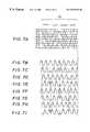
- FIGS. 4A to 4 Eshow a servo information format.
- FIG. 4Ashows a pattern of the servo information SB
- FIGS. 4B to 4 Eshow reproduction signal waveforms of the tracks Tr 0 to Tr 3 .
- the servo information SBconsists of three positional regions “even 1 ”, “odd 1 ”, and “even 2 ”.
- the phase of the signal patternis set at 0° on the track Tr 0 , the phase is +90° on the track Tr 1 , +180° on the track Tr 2 , and +270° on the track Tr 3 .
- the phaseis back at 0° on the track Tr 4 .
- phase of the signal patternis set at 0° on the track Tr 0 , the phase is ⁇ 90° on the track Tr 1 , ⁇ 180° on the track Tr 2 , and ⁇ 270° on the track Tr 3 .
- the phaseis back at 0° on the track Tr 4 .
- the phase of the signal patternis set at 0° on the track Tr 0 , the phase is +90° on the track Tr 1 , +180° on the track Tr 2 , and +270° on the track Tr 3 .
- the phaseis back at 0° on the track Tr 4 .
- the tracks Trcan be identified in accordance with the phase difference in the positional regions “even 1 ”, “odd 1 ”, and “even 2 ”.
- FIG. 5shows an operation of the conventional magnetic disk device.
- the tracks Tr 0 , Tr 2 , and Tr 4can be identified.
- the tracks Tr 1 , Tr 3 , and Tr 5can be identified.
- the servo circuit 9detects the phase difference of the reproduction signals of the positional regions “even 1 ”, “odd 1 ”, and “even 2 ” so as to detect the position of the head, i.e., the track being scanned by the head.
- FIG. 6shows an operation of the conventional magnetic disk device.
- the servo circuit 9calculates the position (Pos) of the head from the formula:
- Pe 1 , Pe 2 , and Po 1are phase differences between detection signal and a predetermined track in the positional regions “even 1 ”, “odd 1 ”, and “even 2 ”, respectively, and (Pe 1 , Pe 2 ) indicates the average value between Pe 1 and Pe 2 .
- the phase of the position of the headis 0°. Accordingly, it can be judged that the head is scanning the reference track
- the phase of the vector e 1is +90°
- the phase of the vector o 1is ⁇ 90°
- the phase of the vector e 2is +90°. Accordingly, the phase difference of Pos is +180°, and it can be judged that the head is situated on the track Tr 1 , which deviates from the reference track Tr 0 by one track.
- the phase of the vector e 1is +180°
- the phase of the vector o 1is ⁇ 180°
- the phase of the vector e 2is +180°. Accordingly, the phase difference of Pos becomes 0°. This cannot be distinguished from the phase difference of the reference track Tr 0 , and the head cannot be judged to be situated on the track Tr 2 .
- the phase of the vector e 1is +270°
- the phase of the vector o 1is ⁇ 270°
- the phase of the vector e 2is +270°. Accordingly, the phase difference of Pos becomes 180°. This cannot be distinguished from the phase difference of the reference track Tr 1 , and the head cannot be judged to be situated on the track Tr 3 .
- the conventional servo circuit 9can detect the position of the head only when the head deviates from the reference track Tr 0 by one track.
- the positional information obtained from the phase differenceis 0° or 180°, as shown in FIG. 6 . From the positional information, only 1-track displacement can be detected. Because of this, when the head is greatly displaced from the reference track, the servomechanism cannot work properly.
- a general object of the present inventionis to provide a servo control method and an information storage device in which the above disadvantages are eliminated.
- a more specific object of the present inventionis to provide a servo control method and a magnetic disk device which can detect a wide range of displacement.
- a servo control method and an information storage devicein which servo control is performed in accordance with servo information including four positional regions having phase differences between tracks.
- One of the positional regionshas a phase difference between tracks different from the other three positional regions.
- the servo controlcan be performed at high speed.
- FIG. 1illustrates a conventional magnetic disk device
- FIG. 2shows a conventional magnetic disk format
- FIG. 3shows a conventional track format
- FIGS. 4A to 4 Eshow a conventional servo information format
- FIG. 5shows an operation of the conventional magnetic disk device
- FIG. 6shows an operation of the conventional magnetic disk device
- FIGS. 7A to 7 Ishow a format of servo information of an embodiment of the present invention
- FIG. 8shows an operation of the embodiment of the present invention
- FIG. 9shows the operation of the embodiment of the present invention.
- FIG. 10shows the operation of the embodiment of the present invention.
- FIG. 11shows the operation of the embodiment of the present invention.
- FIGS. 7A to 7 Ishow a format of servo information of one embodiment of the present invention.
- FIG. 7Ais a servo information format
- FIGS. 7B to 7 Iare reproduction signal waveforms of the respective tracks.
- a magnetic disk device of this embodimentis the same as the device shown in FIG. 1 .
- Servo information SB stored on the magnetic disk 2 in advancehas a fourth positional region “odd 2 ” as well as the positional regions “even 1 ”, “odd 1 ”, and “even 2 ” shown in FIG. 3 .
- the phase difference among the tracks Tr 0 to Tr 7is set at ⁇ 135°, for instance.
- the phase differenceis not limited to this, and it may also be ⁇ 112.5°.
- the phase of the signal patternis ⁇ 135° on the track Tr 1 , ⁇ 270° on the track Tr 2 , ⁇ 405° (i.e., ⁇ 45°) on the track Tr 3 , ⁇ 540° (i.e., ⁇ 180°) on the track Tr 4 , ⁇ 675° (i.e., +45°) on the track Tr 5 , ⁇ 810° (i.e., ⁇ 90°) on the track Tr 6 , ⁇ 945° (i.e., +135°) on the track Tr 7 , and ⁇ 1080° (i.e., 0°) on the track Tr 8 .
- FIG. 8shows an operation of this embodiment.
- the phase difference between the positional regions “odd 1 ” and “odd 2 ”is 45° on the track Tr 1 displaced from the reference track Tr 0 by one track, 90° on the track Tr 2 displaced from the reference track Tr 0 by two tracks, 135° on the track Tr 3 displaced from the reference track Tr 0 by three tracks, 180° on the track Tr 4 displaced from the reference track Tr 0 by four tracks, 225° on the track Tr 5 displaced from the reference track Tr 0 by five tracks, 270° on the track Tr 6 displaced from the reference track Tr 0 by six tracks, and 315° on the track Tr 7 displaced from the reference track Tr 0 by seven tracks.
- FIG. 9also shows the operation of this embodiment.
- the servo circuit 9identifies the positional information Pos from the phase difference between vectors o 1 and o 2 of the positional regions “odd 1 ” and “odd 2 ”, respectively.
- phase difference between the vectors o 1 and o 2is 0° on the reference track Tr 0 .
- the phase of the vector o 1is ⁇ 90°
- the phase of the vector o 2is ⁇ 135°. Accordingly, the phase difference between the vectors o 1 and o 2 is +45° on the track Tr 1 .
- the phase of the vector o 1is ⁇ 180°, and the phase of the vector o 2 is ⁇ 270°. Accordingly, the phase difference between the vectors o 1 and o 2 is +90° on the track Tr 2 .
- the phase of the vector o 1is ⁇ 270°
- the phase of the vector o 2is ⁇ 405°, i.e., ⁇ 45°. Accordingly, the phase difference between the vectors o 1 and o 2 is +135° on the track Tr 3 .
- the phase of the vector o 1is ⁇ 360°
- the phase of the vector o 2is ⁇ 540°, i.e., ⁇ 180°. Accordingly, the phase difference between the vectors o 1 and o 2 is +180° on the track Tr 4 .
- the phase of the vector o 1is ⁇ 450°, i.e., ⁇ 90°
- the phase of the vector o 2is ⁇ 675°, i.e., +45°. Accordingly, the phase difference between the vectors o 1 and o 2 is ⁇ 135° on the track Tr 5 .
- the phase of the vector o 1is ⁇ 540°, i.e., ⁇ 180°
- the phase of the vector o 2is ⁇ 810°, i.e., ⁇ 90°. Accordingly, the phase difference between the vectors o 1 and o 2 is ⁇ 90° on the track Tr 6 .
- the phase of the vector o 1is ⁇ 630°, i.e., ⁇ 270°
- the phase of the vector o 2is ⁇ 945°, i.e., +135°. Accordingly, the phase difference between the vectors o 1 and o 2 is ⁇ 45° on the track Tr 7 .
- the eight tracks including the reference track Tr 0can be distinguished in accordance with the phase difference between the vectors o 1 and o 2 .
- the actual positional information Posis calculated as follows.
- a velocity correction element Veis calculated from a difference between the velocity information obtained by the observer in the servo circuit 9 and the velocity information to be controlled.
- a time correction element Tis detected from sin ⁇ and cos ⁇ of the phase difference ⁇ between the positional regions “even 1 ” and “even 2 ”.
- FIG. 10shows the operation of this embodiment.
- the vector indicating the phase of the positional region “even 1 ”is e 1
- the vector indicating the phase of the positional region “even 2 ”is e 2
- the product of the magnitudes of e 1 and e 2is r.
- VeT - 1( cos ⁇ ⁇ ⁇ sin ⁇ ⁇ ⁇ - sin ⁇ ⁇ ⁇ cos ⁇ ⁇ ⁇ ) ( 2 )
- the inverse matrix T ⁇ 1is determined by substituting the velocity correction element Ve and the equation (2) in the equation (3).
- Tis the time correction element
- Vois the velocity correction element
- Posis the positional information
- o 1 and o 2are the vectors of the positional regions “odd 1 ” and “odd 2 ”.
- T ⁇ Vo ⁇ Pos( cos ⁇ ⁇ ⁇ sin ⁇ ⁇ ⁇ - sin ⁇ ⁇ ⁇ cos ⁇ ⁇ ⁇ ) ( 6 )
- the positional information Posis demodulated by the equation (8).
- FIG. 11shows the operation of this embodiment.
- the magnetic head 4scans, only 1-track displacement can be detected in the prior art.
- a wide range of displacementcan be detected in accordance with the servo information SB 0 to SB 4 . Even if the magnetic head 4 is deviated by vibration, the position of the head 4 is easily detected, so that the magnetic head 4 can be immediately returned to the original position.
- the magnetic disk deviceis employed, but the present invention can also be applied to an optical disk or the like.
Landscapes
- Moving Of The Head To Find And Align With The Track (AREA)
Abstract
Description


Claims (12)
Applications Claiming Priority (2)
| Application Number | Priority Date | Filing Date | Title |
|---|---|---|---|
| JP10-340556 | 1998-11-30 | ||
| JP34055698AJP3340077B2 (en) | 1998-11-30 | 1998-11-30 | Servo control method and information storage device |
Publications (1)
| Publication Number | Publication Date |
|---|---|
| US6535348B1true US6535348B1 (en) | 2003-03-18 |
Family
ID=18338132
Family Applications (1)
| Application Number | Title | Priority Date | Filing Date |
|---|---|---|---|
| US09/413,649Expired - LifetimeUS6535348B1 (en) | 1998-11-30 | 1999-10-06 | Servo control method and information storage device |
Country Status (4)
| Country | Link |
|---|---|
| US (1) | US6535348B1 (en) |
| EP (1) | EP1006512B1 (en) |
| JP (1) | JP3340077B2 (en) |
| DE (1) | DE69938166T2 (en) |
Cited By (8)
| Publication number | Priority date | Publication date | Assignee | Title |
|---|---|---|---|---|
| US20060245105A1 (en)* | 2005-04-27 | 2006-11-02 | Kabushiki Kaisha Toshiba | Method and apparatus for servo control in a disk drive |
| US20080055770A1 (en)* | 2006-08-30 | 2008-03-06 | Fujitsu Limited | Control device, storage device, method of demodulating servo information, and computer product |
| US20080055769A1 (en)* | 2006-08-30 | 2008-03-06 | Fujitsu Limited | Control device, storage device, storage medium, servo data demodulation method, repeatable velocity error measuring device, and computer product |
| US20080159092A1 (en)* | 2006-12-27 | 2008-07-03 | Fujitsu Limited | Medium storage device, position demodulation device and position demodulation method |
| US20080239553A1 (en)* | 2007-04-02 | 2008-10-02 | Fujitsu Limited | Storage apparatus and head position demodulating apparatus |
| US7453663B1 (en)* | 2004-06-09 | 2008-11-18 | Maxtor Corporation | Disk drives with servo burst patterns radially offset in different radial spokes of a disk and methods of positioning based thereon |
| US20100302675A1 (en)* | 2009-05-26 | 2010-12-02 | Toshiba Storage Device Corporation | Storage medium and method and program for detecting track position of storage medium |
| US20150146318A1 (en)* | 2013-11-25 | 2015-05-28 | Kabushiki Kaisha Toshiba | Head position demodulation method and magnetic disk device |
Families Citing this family (1)
| Publication number | Priority date | Publication date | Assignee | Title |
|---|---|---|---|---|
| JP3877133B2 (en) | 2001-02-16 | 2007-02-07 | 富士通株式会社 | Signal reproduction method and storage device |
Citations (12)
| Publication number | Priority date | Publication date | Assignee | Title |
|---|---|---|---|---|
| GB1127563A (en) | 1966-03-02 | 1968-09-18 | Ibm | Improvements in or relating to memory systems employing a magnetic recording medium |
| EP0034938A2 (en) | 1980-02-22 | 1981-09-02 | Northern Telecom Inc. | A servo system and method for positioning a read/write transducer relative to a storage medium and a recording medium for use in such a system and method |
| US4490756A (en)* | 1982-11-01 | 1984-12-25 | International Business Machines Corporation | Servo encodement and detection system using tetra-orthogonal servo pattern |
| JPS6010472A (en) | 1983-06-27 | 1985-01-19 | インタ−ナショナル ビジネス マシ−ンズ コ−ポレ−ション | Rotary recording medium with servo pattern recorded |
| US5343340A (en)* | 1992-12-31 | 1994-08-30 | International Business Machines Corporation | Digital servo signal demodulation method and apparatus utilizing a partial-response maximum-likelihood (PRML) channel in a disk file |
| JPH06243574A (en) | 1993-02-19 | 1994-09-02 | Fujitsu Ltd | Servo position detector for disk device |
| JPH07287949A (en) | 1994-04-19 | 1995-10-31 | Fujitsu Ltd | Disk device |
| JPH07334948A (en) | 1994-06-03 | 1995-12-22 | Fujitsu Ltd | Disk device |
| JPH09180386A (en) | 1995-12-28 | 1997-07-11 | Fujitsu Ltd | Disk device, phase demodulating device for disk device, and phase demodulating method of disk device |
| US5694265A (en) | 1994-04-19 | 1997-12-02 | Fujitsu Limited | Disk apparatus for detecting position of head by reading phase servo pattern |
| US5892634A (en)* | 1995-05-23 | 1999-04-06 | Kabushiki Kaisha Toshiba | Method and apparatus for heat positioning control in disk storage system |
| US6172836B1 (en)* | 1995-12-29 | 2001-01-09 | Samsung Electronics Co., Ltd. | Method and apparatus for writing the servo pattern for detecting fine defects in the servo burst signals of a hard disk drive |
- 1998
- 1998-11-30JPJP34055698Apatent/JP3340077B2/ennot_activeExpired - Fee Related
- 1999
- 1999-10-06USUS09/413,649patent/US6535348B1/ennot_activeExpired - Lifetime
- 1999-10-07DEDE69938166Tpatent/DE69938166T2/ennot_activeExpired - Fee Related
- 1999-10-07EPEP99307925Apatent/EP1006512B1/ennot_activeExpired - Lifetime
Patent Citations (15)
| Publication number | Priority date | Publication date | Assignee | Title |
|---|---|---|---|---|
| GB1127563A (en) | 1966-03-02 | 1968-09-18 | Ibm | Improvements in or relating to memory systems employing a magnetic recording medium |
| EP0034938A2 (en) | 1980-02-22 | 1981-09-02 | Northern Telecom Inc. | A servo system and method for positioning a read/write transducer relative to a storage medium and a recording medium for use in such a system and method |
| US4490756A (en)* | 1982-11-01 | 1984-12-25 | International Business Machines Corporation | Servo encodement and detection system using tetra-orthogonal servo pattern |
| JPS6010472A (en) | 1983-06-27 | 1985-01-19 | インタ−ナショナル ビジネス マシ−ンズ コ−ポレ−ション | Rotary recording medium with servo pattern recorded |
| US4549232A (en) | 1983-06-27 | 1985-10-22 | International Business Machines Corporation | Phase modulated servo system |
| US5343340A (en)* | 1992-12-31 | 1994-08-30 | International Business Machines Corporation | Digital servo signal demodulation method and apparatus utilizing a partial-response maximum-likelihood (PRML) channel in a disk file |
| JPH06243574A (en) | 1993-02-19 | 1994-09-02 | Fujitsu Ltd | Servo position detector for disk device |
| US5523900A (en) | 1993-02-19 | 1996-06-04 | Fujitsu Limited | Head position detecting method and apparatus |
| JPH07287949A (en) | 1994-04-19 | 1995-10-31 | Fujitsu Ltd | Disk device |
| US5694265A (en) | 1994-04-19 | 1997-12-02 | Fujitsu Limited | Disk apparatus for detecting position of head by reading phase servo pattern |
| JPH07334948A (en) | 1994-06-03 | 1995-12-22 | Fujitsu Ltd | Disk device |
| US5892634A (en)* | 1995-05-23 | 1999-04-06 | Kabushiki Kaisha Toshiba | Method and apparatus for heat positioning control in disk storage system |
| JPH09180386A (en) | 1995-12-28 | 1997-07-11 | Fujitsu Ltd | Disk device, phase demodulating device for disk device, and phase demodulating method of disk device |
| US5757576A (en) | 1995-12-28 | 1998-05-26 | Fujitsu Limited | Disk apparatus, and phase demodulating device and method for a disk apparatus |
| US6172836B1 (en)* | 1995-12-29 | 2001-01-09 | Samsung Electronics Co., Ltd. | Method and apparatus for writing the servo pattern for detecting fine defects in the servo burst signals of a hard disk drive |
Non-Patent Citations (1)
| Title |
|---|
| IBM Technical Disclosure Bulletin, vol. 29 no. 8 (1987) pp. 3697-3699 "Disk File Phase-Encoded Sector Servo Pattern With Data And Reference Fields In Each Sector". |
Cited By (13)
| Publication number | Priority date | Publication date | Assignee | Title |
|---|---|---|---|---|
| US7453663B1 (en)* | 2004-06-09 | 2008-11-18 | Maxtor Corporation | Disk drives with servo burst patterns radially offset in different radial spokes of a disk and methods of positioning based thereon |
| US20060245105A1 (en)* | 2005-04-27 | 2006-11-02 | Kabushiki Kaisha Toshiba | Method and apparatus for servo control in a disk drive |
| US7312946B2 (en) | 2005-04-27 | 2007-12-25 | Kabushiki Kaisha Toshiba | Method and apparatus for servo control in a disk drive |
| US20080055769A1 (en)* | 2006-08-30 | 2008-03-06 | Fujitsu Limited | Control device, storage device, storage medium, servo data demodulation method, repeatable velocity error measuring device, and computer product |
| US20080055770A1 (en)* | 2006-08-30 | 2008-03-06 | Fujitsu Limited | Control device, storage device, method of demodulating servo information, and computer product |
| US7463439B2 (en) | 2006-08-30 | 2008-12-09 | Fujitsu Limited | Control device, storage device, storage medium, servo data demodulation method, repeatable velocity error measuring device, and computer product |
| US7551391B2 (en) | 2006-08-30 | 2009-06-23 | Fujitsu Limited | System and method for controlling head velocity by demodulating servo information |
| US20080159092A1 (en)* | 2006-12-27 | 2008-07-03 | Fujitsu Limited | Medium storage device, position demodulation device and position demodulation method |
| KR100922410B1 (en)* | 2006-12-27 | 2009-10-16 | 후지쯔 가부시끼가이샤 | Medium storage device, position demodulation device and position demodulation method |
| US20080239553A1 (en)* | 2007-04-02 | 2008-10-02 | Fujitsu Limited | Storage apparatus and head position demodulating apparatus |
| US20100302675A1 (en)* | 2009-05-26 | 2010-12-02 | Toshiba Storage Device Corporation | Storage medium and method and program for detecting track position of storage medium |
| US20150146318A1 (en)* | 2013-11-25 | 2015-05-28 | Kabushiki Kaisha Toshiba | Head position demodulation method and magnetic disk device |
| US9177581B2 (en)* | 2013-11-25 | 2015-11-03 | Kabushiki Kaisha Toshiba | Head position demodulation method and magnetic disk device |
Also Published As
| Publication number | Publication date |
|---|---|
| EP1006512A1 (en) | 2000-06-07 |
| EP1006512B1 (en) | 2008-02-20 |
| JP3340077B2 (en) | 2002-10-28 |
| JP2000173210A (en) | 2000-06-23 |
| DE69938166T2 (en) | 2009-02-19 |
| DE69938166D1 (en) | 2008-04-03 |
Similar Documents
| Publication | Publication Date | Title |
|---|---|---|
| US5235478A (en) | Disc drive apparatus with servo tracks offset from data tracks | |
| US20020012188A1 (en) | Data recording and/or reproducing apparatus, and disc-shaped recording medium | |
| US6535348B1 (en) | Servo control method and information storage device | |
| US5148420A (en) | Recording information apparatus having a head speed detector | |
| EP0538835B1 (en) | Recording and reproducing apparatus | |
| EP0145787A1 (en) | Apparatus for controlling tracking of recorded disc reproduction device | |
| US4884152A (en) | Method for restoring track 0 | |
| US6307704B1 (en) | Data recording medium and data recording/reproducing device with increased storage capacity | |
| US5475660A (en) | Optical information recording-reproducing method and apparatus including focusing and/or tracking control depending on a determined state of an optical spot | |
| JPH02246064A (en) | Head positional deviation correcting method | |
| EP0250138B1 (en) | Servo system for a hard disk drive | |
| JP2523316B2 (en) | Method and apparatus for recording servo data on magnetic disk | |
| JPH05298840A (en) | Magnetic disk driving device | |
| US7173789B2 (en) | Head position calculation method in magnetic disc apparatus | |
| JPS623475A (en) | magnetic disk | |
| JPH1153851A (en) | Magnetic disk and magnetic disk device | |
| US20040150906A1 (en) | Servo writing method, servo writer, and program thereof | |
| JP2555180B2 (en) | Tracking servo information error detection method | |
| JPH0877538A (en) | Magnetic disk unit | |
| JPH03113783A (en) | How to control a magnetic disk device | |
| JPS6150259A (en) | Magnetic disc device | |
| JPH07192411A (en) | Method for correcting positional error signal of magnetic disk device | |
| JPH052726A (en) | Control method for recording and reproducing device | |
| JPH06150475A (en) | Magnetic recording / reproducing device | |
| JPH1049805A (en) | Magnetic disk drive and noise compensation method for the same |
Legal Events
| Date | Code | Title | Description |
|---|---|---|---|
| AS | Assignment | Owner name:FUJITSU LIMITED, JAPAN Free format text:ASSIGNMENT OF ASSIGNORS INTEREST;ASSIGNORS:KAGAMI, YOSHIYUKI;KOSUGI, TATSUHIKO;REEL/FRAME:010306/0389 Effective date:19990809 | |
| STCF | Information on status: patent grant | Free format text:PATENTED CASE | |
| FEPP | Fee payment procedure | Free format text:PAYOR NUMBER ASSIGNED (ORIGINAL EVENT CODE: ASPN); ENTITY STATUS OF PATENT OWNER: LARGE ENTITY | |
| FPAY | Fee payment | Year of fee payment:4 | |
| AS | Assignment | Owner name:TOSHIBA STORAGE DEVICE CORPORATION, JAPAN Free format text:ASSIGNMENT OF ASSIGNORS INTEREST;ASSIGNOR:FUJITSU LIMITED;REEL/FRAME:023419/0031 Effective date:20091014 Owner name:TOSHIBA STORAGE DEVICE CORPORATION, JAPAN Free format text:ASSIGNMENT OF ASSIGNORS INTEREST;ASSIGNOR:FUJITSU LIMITED;REEL/FRAME:023861/0881 Effective date:20091014 Owner name:TOSHIBA STORAGE DEVICE CORPORATION,JAPAN Free format text:ASSIGNMENT OF ASSIGNORS INTEREST;ASSIGNOR:FUJITSU LIMITED;REEL/FRAME:023861/0881 Effective date:20091014 | |
| XAS | Not any more in us assignment database | Free format text:ASSIGNMENT OF ASSIGNORS INTEREST;ASSIGNOR:FUJITSU LIMITED;REEL/FRAME:023419/0031 | |
| FPAY | Fee payment | Year of fee payment:8 | |
| AS | Assignment | Owner name:KABUSHIKI KAISHA TOSHIBA, JAPAN Free format text:ASSIGNMENT OF ASSIGNORS INTEREST;ASSIGNOR:TOSHIBA STORAGE DEVICE CORPORATION;REEL/FRAME:027590/0695 Effective date:20120113 | |
| FPAY | Fee payment | Year of fee payment:12 |