US6534936B2 - Disk drive employing method of spinning up spindle motor including detecting BEMF polarity change for selecting initial commutation state - Google Patents
Disk drive employing method of spinning up spindle motor including detecting BEMF polarity change for selecting initial commutation stateDownload PDFInfo
- Publication number
- US6534936B2 US6534936B2US09/560,918US56091800AUS6534936B2US 6534936 B2US6534936 B2US 6534936B2US 56091800 AUS56091800 AUS 56091800AUS 6534936 B2US6534936 B2US 6534936B2
- Authority
- US
- United States
- Prior art keywords
- spindle motor
- rotor
- windings
- spin
- voltage
- Prior art date
- Legal status (The legal status is an assumption and is not a legal conclusion. Google has not performed a legal analysis and makes no representation as to the accuracy of the status listed.)
- Expired - Lifetime, expires
Links
Images


Classifications
- G—PHYSICS
- G11—INFORMATION STORAGE
- G11B—INFORMATION STORAGE BASED ON RELATIVE MOVEMENT BETWEEN RECORD CARRIER AND TRANSDUCER
- G11B19/00—Driving, starting, stopping record carriers not specifically of filamentary or web form, or of supports therefor; Control thereof; Control of operating function ; Driving both disc and head
- G11B19/20—Driving; Starting; Stopping; Control thereof
Definitions
- the present inventiongenerally relates to spinning up a spindle motor in a hard disk drive. More particularly, the present invention relates to a disk drive employing a method of spinning up a spindle motor including detecting back electromotive force (BEMF) polarity change for selecting an initial commutation state for the spindle motor.
- BEMFback electromotive force
- a hard disk drivemust be relatively inexpensive, and must accordingly embody a design that is adapted for low-cost mass production.
- itmust provide substantial capacity, rapid access to data, and reliable performance.
- Numerous manufacturerscompete in this huge market and collectively conduct substantial research and development, at great annual cost, to design and develop innovative hard disk drives to meet increasingly demanding customer requirements.
- hard disk drivesdata is stored on magnetic media disks in concentric data tracks, which are divided into groups of data sectors. Disks are typically stacked on a spindle assemble.
- the spindle assemblyis mechanically coupled to a spindle motor which rotates the disks at a substantially constant operating spin-rate.
- the hard disk driveperforms a spin-up operation to bring previously stopped disks to the operating spin-rate.
- mass-market hard disk driveshaving faster spin-up operations to more quickly begin reading from and/or writing to the magnetic disks after the disks are spun-down to zero or other spin-rate lower than the operating spin-rate, especially after power-on of the computer system that employs the hard disk drive.
- a spindle motor drivertypically drives the spindle motor.
- a typical three-phase spindle motorincludes a stator having three windings and a rotor.
- the rotorhas magnets that provide a permanent magnet field.
- the spindle motorgenerates torque on the rotor when current flows through at least one of the windings.
- the torquedepends on upon the magnitude and direction of current flow through the windings and an angular position of the rotor relative to the stator.
- the functional relationship between torque and current flow and angular positionis commonly depicted in a set of torque curves, each of which corresponds to a respective one of a set of commutation states.
- Conventional spin-up operations in hard disk drivesinclude a cogging operation which cogs or prepositions the rotor at a fixed angular phase position.
- the following example conventional spin-up operation datais provided for an example multi-platter disk drive.
- the cogging operationis performed at zero revolutions per minute (RPM) spin-rate.
- An example cogging operationtakes approximately 1.3 seconds.
- a blind table operationwhere the velocity of the spindle motor is not monitored, typically is performed for approximately 0.3 seconds from 0 to approximately 400 RPMs.
- the blind table operationstarts the rotor at the cogged fixed angular position and a corresponding predetermined initial commutation state is used to initially a control the spindle motor to generate a positive torque to move the disks in a forward direction.
- an approximately 100 millisecond sync-up operationis typically required to sync-up the spindle motor to permit monitoring of its spin-rate.
- a back electromotive force (BEMF) spin-up operationbegins at the approximately 400 RPM spin-rate to spin-up to an operating spin-rate, such as 5,400 or 7,200 RPMs.
- the BEMF spin-up operationmonitors the BEMF of the spindle motor to thereby monitor the spin-rate of the disks. After reaching the operating spin-rate, the spin-up operation is finished and control is handed off to the run mode operation of the spindle motor.
- the cogging operationtakes up a substantial portion of the spin-up operation in the disk drive. Furthermore, in the case of ramp load operations, there is no head on media friction during the spin-up operation. In this case, the cog operation can oscillate for many seconds without the damping effect provided by the head on the disk media.
- the inventioncan be regarded as a method of spinning-up a spindle motor to an operating spin-rate during a spin-up operation in a disk drive.
- the spindle motorhas a plurality of windings and a rotatable rotor.
- the methodincludes the step of applying a voltage across at least one of the windings to cause the rotor to rotate.
- the rotating rotorinduces a BEMF having a polarity across each of the windings.
- the methodalso includes the step of removing the applied voltage across the windings.
- the methodsubsequently detects the polarity of the BEMF in each of the windings to generate a previous multi-bit sequence representing a previous phase position ( ⁇ circumflex over ( ⁇ ) ⁇ n ) of the rotor.
- the methodthen detects a change in the polarity of the BEMF in one of the windings to generate a present multi-bit sequence representing a present phase position ( ⁇ n ) of the rotor.
- the methoduses the previous phase position ( ⁇ circumflex over ( ⁇ ) ⁇ n ) and the present phase position ( ⁇ n ) of the rotor for selecting an initial commutation state in a spin-up commutation sequence such that the voltage is sequentially applied across a selected combination of the windings in order to spin-up the spindle motor to the operating spin-rate.
- the inventioncan also be regarded as a disk drive connectable to a power supply voltage.
- the disk driveincludes a spindle motor having a plurality of windings and a rotatable rotor.
- the disk drivealso includes a spindle motor driver connected to the windings and connectable to the voltage.
- the disk drivealso includes a spindle motor controller for commanding the spindle motor driver to apply the voltage across at least one of the windings to cause the rotor to rotate.
- the rotating rotorinduces a BEMF having a polarity across each of the windings.
- the spindle motor controllersubsequently commands the spindle motor driver to remove the applied voltage across the windings.
- the disk drivealso includes a detector for monitoring the BEMF in each of the windings while the voltage is removed across the windings.
- the detectorperforms the steps of detecting the polarity of the BEMF in each of the windings to generate a previous multi-bit sequence representing a previous phase position ( ⁇ circumflex over ( ⁇ ) ⁇ n ) of the rotor and detecting a change in the polarity of the BEMF in one of the windings to generate a present multi-bit sequence representing a present phase position ( ⁇ n ) of the rotor.
- FIG. 1is a block diagram of a hard disk drive according to an embodiment of the present invention.
- FIG. 2is a more detailed schematic diagram of a portion of the hard disk drive of FIG. 1 .
- FIG. 3Ais a diagram illustrating an example set of torque curves for a spindle motor of the hard disk of FIG. 1 which depict the functional relationship between torque, current flow, and angular position.
- FIG. 3Bis a diagram corresponding to FIG. 3A which plots the BEMF for each of the spindle motor windings versus the angular positions plotted in the torque curves of FIG. 3 A.
- FIG. 4is a block flow diagram illustrating a method of spinning-up a spindle motor in the hard disk drive of FIG. 1 to an operating spin-rate.
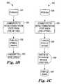
- FIGS. 5A-Dtogether form a block flow diagram of one embodiment of a cogless spin-up routine operating in the hard disk drive of FIG. 1 .
- a disk drive 8employs a method of spinning up a spindle motor, such as a spindle motor 16 , by detecting back electromotive force (BEMF) polarity changes for selecting an initial commutation state for the spindle motor.
- BEMFback electromotive force
- Disk drive 8includes a head disk assembly (HDA) 10 and a printed circuit board assembly (PCBA) 12 .
- HDA 10includes a suitable number of magnetic disks 14 stacked on a spindle assembly 15 , spindle motor 16 , a voice coil motor (VCM) 18 , and a preamplifier 22 .
- Spindle motor 16is mechanically coupled to spindle assembly 15 to cause disks 14 to rotate at a high spin-rate.
- each disk 14provides two recording surfaces.
- Each of the recording surfaceshas a plurality of data tracks.
- the data tracksare arranged in an embedded servo format having interspersed servo-information regions and user-data regions.
- Transducers 20Each of a suitable number of transducers 20 provides for reading from and writing to a respective one of the recording surfaces of disks 14 .
- Transducers 20can include separate read and write transducers. When reading, each transducer 20 generates a low level analog read signal 17 b . Analog read signal 17 b is conveyed to signal inputs of preamplifier 22 .
- Preamplifier 22produces a read signal 24 which is an amplified analog read signal.
- HDA 10also includes a path for conveying read signal 24 to PCBA 12 ; a path for conveying a write data signal 28 to preamplifier 22 ; and a path for conveying preamplifier control signals 30 for preamplifier 22 . Under control of control signals 30 , preamplifier 22 operates in either a read mode or a write mode and in either case communicates with a selected transducer 20 .
- preamplifier 22provides write current via a write data signal 17 a to a selected transducer 20 for writing a sequence of symbols on one of the recording surfaces of disk 14 .
- the write currentchanges polarity upon each change in binary value of write data signal 28 .
- low level read signal 17 b(and corresponding amplified read signal 24 ) serially defines servo information and user data.
- the servo informationincludes gross-positioning data information including track identification data information, and fine-positioning information in the form of analog servo bursts.
- spindle motor 16is a multi phase, brushless DC motor.
- Disk drive 8employs a method according to the present invention for controlling spindle motor 16 to spin up to a substantially constant annular velocity, as described in more detail below.
- Well known techniquescan be employed for controlling spindle motor 16 to spin down from, the substantially constant angular velocity.
- PCBA 12includes a channel 26 and a host interface and disk controller (“HIDC 32 ”).
- channel 26 and HIDC 32are each implemented as a single IC, and these two ICs in combination perform overall functions including basic timing functions.
- One such basic timing functionentails the generation of the “global clock” and the synchronization of the global clock to the servo sample rate.
- HIDC 32contains circuitry for generating the global clock which is synchronized to the servo sample rate by a signal supplied by channel 26 .
- HIDC 32contains timing circuitry controlled by the global clock to provide timing signals used in de-multiplexing including separating servo data information from servo bursts and from user data.
- channel 26includes the global clock and timer circuitry.
- Channel 26is coupled to receive read signal 24 and provides a signal processing path (i.e., read channel) for processing read signal 24 to produce a clocked, serial-by-symbol data signal (i.e., a decoded binary data signal and accompanying clock signal).
- Channel 26also provides a signal processing path (i.e., write channel) for processing a clocked serial-by-symbol data signal provided by HIDC 32 to produce serial-by-bit write data signal 28 for the analog signal input of preamplifier 22 .
- the serial-by-symbol data signalspropagate between a port 40 in channel 26 and a port 45 in HIDC 32 via a channel data bus 38 .
- the clock signals for the serial-by-symbol data signals between channel 26 and HIDC 32are indicated as CLOCKING 41 .
- HIDC 32performs numerous control functions for disk drive 8 including host interface functions to manage transfer of data between the disk drive and the host, and certain disk controller functions to manage the operation of channel 26 in writing and reading data. Incident to such disk controller functions, HIDC 32 has circuitry for producing certain timing and control signals that are part of a set identified collectively as timing and control (CNTRLS) signals 44 which are sent between channel 26 and HIDC 32 .
- CNTRLStiming and control
- PCBA 12also includes a data buffer 42 , a microprocessor 34 , a read only memory (ROM) 54 , a writeable random access memory (RAM) 60 , a VCM driver 58 for supplying current to VCM 18 , and a spindle motor driver 56 for supplying current to spindle motor 16 .
- VCM driver 58 and spindle motor driver 56are implemented in a power device 59 .
- Microprocessor 34executes instructions acquired from a stored control program to control disk drive functions. These functions include reading and decoding host commands, starting up and controlling the speed of spindle motor 16 via HIDC 32 , minimizing head-positioning servo off track error through control of VCM 18 , managing reduced power modes of operation, and other disk drive functions. Microprocessor 34 includes an I/O port that is connected to microprocessor bus 36 .
- Microprocessor 34suitably includes an embedded ROM or other non-volatile memory, such as flash memory, that stores some of the control programs it uses.
- control programsinclude the instructions microprocessor 34 executes, and tables, parameters or arguments used during the execution of these programs.
- Microprocessor control programsmay also reside in any or all of ROM 54 , RAM 60 , or data buffer 42 .
- Microprocessor 34 suitablealso includes a register set and a RAM.
- ROM 54is an optional conventional ROM IC that stores at least part of the control program used by microprocessor 34 .
- ROM 54may be omitted in an embodiment in which microprocessor 34 includes embedded ROM suitable for replacing the functions of ROM 54 .
- ROM 54is replaced by programmable non-volatile memory, such as flash memory.
- Channel 26has a port 46 and HIDC 32 has a port 35 that connect to microprocessor bus 36 to permit microprocessor 34 to directly communicate with channel 26 and HIDC 32 .
- Microprocessor bus 36also enables microprocessor 34 to communicate directly with ROM 54 and RAM 60 .
- Channel 26includes circuitry to process read signal 24 , and, on a time-multiplexed basis, generate decoded digital user data, decoded digital servo information data, and a digital representation of demodulated servo burst data.
- the decoded digital servo information data and decoded digital user dataare conveyed to HIDC 32 via port 40 , channel data bus 38 , and port 45 .
- Microprocessor 34acquires the demodulated servo burst data via microprocessor port 46 and microprocessor bus 36 , and uses the demodulated servo burst data to perform fine-position head-positioning servo operations.
- An alternative embodimentincorporates servo control circuitry in a servo IC in which case the demodulated servo burst data is provided to such IC.
- HIDC 32also includes a buffer port 37 connected to buffer bus 48 , and host interface port 33 connected to host-interface bus 50 .
- HIDC 32includes buffer manager-arbitrator circuitry that manages access to data buffer 42 and manages bi-directional exchange of data between HIDC 32 and data buffer 42 via buffer bus 48 .
- Host interface port 33provides for communicating with the host via host interface bus 50 and host connection 52 .
- the hostcan be any electronic system, such as a computer system, that has an input/output (I/O) bus and interface connection means that is compatible with host connection 52 , host interface bus 50 , and host interface port 33 .
- I/Oinput/output
- HIDC 32also controls disk formatting and address translation.
- the translating of addressesincludes translating a logical block address to a cylinder/head/sector address and provides for defect management.
- HIDC 32also includes error detection and correction circuitry that is used to correct errors in user data that were read from disks 14 and stored in data buffer 42 .
- Data buffer 42stores data recovered from a disk 14 , data provided by the host to be recorded on a disk 14 , and, optionally, disk drive commands, servo information data, and control aid programs for microprocessor 34 .
- the buffer manager within HIDC 32arbitrates access to data buffer 42 when contention for access to data buffer 42 occurs as a consequence of various concurrent operations. Disk drive commands received from the host may be stored in data buffer 42 and be subsequently retrieved by microprocessor 34 .
- Data buffer 42preferably has sufficient capacity to hold multiple sectors of user data for both read and write operations.
- FIG. 2illustrates certain portions of disk drive 8 relevant to an embodiment of the present invention in more detail in schematic and block diagram form.
- the embodiment of spindle motor 16 illustrated in FIG. 2includes a stator 101 having three windings 104 a (winding A), 104 b (winding B), and 104 c (winding C) electrically arranged in a Y configuration, and a rotor 105 .
- spindle motor 16is implemented in an eight pole, three-phase DC brushless motor.
- Rotor 105has magnets that provide a permanent magnetic field.
- Spindle motor 16generates torque (T d ) on rotor 105 when current (I m ) flows through at least one of windings 104 .
- T ddepends upon the magnitude and direction of current flow through the windings 104 , and the angular position of rotor 105 relative to stator 101 .
- the functional relationship between torque and current flow and angular positionis commonly depicted in a set of torque curves, each of which corresponds to a respective one of a set of commutation states. Such torque curves are illustrated in FIG. 3 and are described in more detail below.
- Various firmware routinesare stored in memory locations in ROM 54 for controlling the operation of spindle motor 16 .
- a programmable startup routine 109a speed controller routine 110 , and a spin-down routine 112 are stored in ROM 54 for controlling spindle motor 16 during start-up, running, and spin-down of spindle motor 16 .
- Microprocessor 34preferably comprises a digital signal processor that runs routines 109 , 110 , and 112 to control spindle motor 16 .
- microprocessor 34responds to a startup command to receive and execute programmable startup instructions from programmable start-up routine 109 of ROM 54 to form a programmable start-up controller 114 within microprocessor 34 .
- microprocessor 34receives and executes speed controller instructions from speed controller routine 110 of ROM 54 to form a speed controller 116 within microprocessor 34 .
- microprocessor 34responds to a spin-down command to receive and execute spin-down instructions from spin-down routine 112 to form a spin-down controller 118 within microprocessor 34 .
- Microprocessor 34 and HIDC 32together function as a spindle motor controller for commanding spindle motor driver 56 to apply a voltage (+V) across at least one winding of windings 104 to cause rotor 105 to rotate. Rotor 105 rotating induces a BEMF having a polarity across each of windings 104 .
- Microprocessor 34 and HIDC 32 functioning as the spindle motor controlleralso subsequently command spindle motor driver 56 to remove the applied voltage (+V) across windings 104 .
- HIDC 32includes address logic 140 , a serial port 142 , a commutation register 144 , and a status register 146 for implementing its portion of the spindle motor controller function.
- Microprocessor 34provides data to serial port 142 and commutation register 144 via microprocessor data bus 36 a .
- Microprocessor 34reads data from status register 146 via microprocessor data bus 36 a .
- Microprocessor 34provides addresses to address logic 140 via microprocessor address bus 36 b .
- Address logic 140responds to the received addresses from microprocessor address bus 36 b to select serial port 142 or commutation register 144 to be written by microprocessor 34 or to select status register 146 to be read by microprocessor 34 .
- write datais provided to and read data is provided from ROM 54 and RAM 60 from/to microprocessor data bus 36 a .
- Addressesare provided from microprocessor 34 to ROM 54 and RAM 60 for writing and reading data via microprocessor address bus 36 b.
- Microprocessor 34serially provides spindle motor commands to serial port 142 of HIDC 32 .
- the spindle motor commandsare generated by programmable start-up controller 114 during start-up operations, by speed controller 116 during run operations, and by spin-down controller 118 during spin-down operations.
- Example spindle motor commandsinclude run commands for controlling the running of spindle motor 16 , coast commands to trigger spindle motor 16 to coast, and brake commands which triggers spindle motor 16 to brake.
- Spindle motor driver 56includes a digital-to-analog converter (DAC) 120 ; a command register 121 ; a commutation state sequencer 122 ; a pulse width modulation (PWM) controller 124 ; a driver control 126 ; switching elements 128 ; a current sense circuit 134 ; an analog switch 136 ; and a comparator 138 .
- Control signals 51provide for bi-directional control interactions between spindle motor driver 56 and HIDC 32 .
- Serial Port 142 of HIDC 32provides a representative form of the microprocessor generated spindle motor commands to command register 121 via a command line 51 a .
- command register 121provides a current command to DAC 120 which correspondingly provides a corresponding analog signal to PWM controller 124 which controls the amount of current supplied to spindle motor 16 .
- Command register 121also provides commands to driver control 126 to control the operation of switching elements 128 based on the type of command in command register 121 .
- Command register 121also provides an initialization command to commutation state sequencer 122 to reset the state of commutation state sequencer to “0” or another predetermined reset state.
- Microprocessor 34writes to commutation register 144 via microprocessor data bus 36 a to change the state of commutation register 144 .
- Commutation register 144responds to this control from microprocessor 34 to provide a commutation clock on clock line 51 b to commutation state sequencer 122 .
- Commutation state sequencer 122increments its state with every new commutation clock pulse from commutation register 144 on clock line 51 b.
- commutation state sequencer 122sequences through a set of six commutation states corresponding to a set of torque curves to control switching elements 128 which drive spindle motor 16 via driver control 126 to maximize the peak positive torque produced by spindle motor 16 .
- speed controller 116 within microprocessor 34provides current commands to command register 121 via serial port 142 .
- the output of command register 121is provided to DAC 120 which converts the current command into an analog signal.
- the analog signal from DAC 120is provided to PWM controller 124 .
- PWM controller 124provides a PWM control signal to power driver control circuit 126 for controlling current flowing through windings 104 a , 104 b , and 104 c .
- Power driver control circuit 126has six lines which are each coupled to a gate of a corresponding one of power metal oxide semiconductor field effect transistors (MOSFETs) 128 a , 128 b , 128 c , 128 d , 128 e , and 128 f.
- MOSFETspower metal oxide semiconductor field effect transistors
- Power MOSFETs 128 a - fform switching elements 128 .
- the drain of power MOSFET 128 ais coupled to the positive power supply and its source is coupled to winding 104 c via a line 132 c .
- Power MOSFET 128 ais paired with power MOSFET 128 b , which has its source coupled to ground and its drain coupled to winding 104 c via line 132 c .
- power MOSFET 128 chas its drain coupled to the positive power supply and its source coupled to winding 104 b via a line 132 b , and is paired with power MOSFET 128 d which has its source coupled to ground and its drain coupled to winding 104 b via line 132 b .
- Power MOSFET 128 ehas its drain coupled to the positive power supply and its source coupled to winding 104 a via a line 132 a , and is paired with power MOSFET 128 f which has its source coupled to ground and its drain coupled to winding 104 a via line 132 a.
- Each power MOSFET pair(i.e., 128 a - 128 b , 128 c - 128 d , and 128 e - 128 f ) form a tri-state switching element.
- Each tri-state switching element 128includes a pair of MOSFETs which are in one of three possible states as follows: 1) the upper MOSFET (e.g., 128 a ) is on and the lower MOSFET (e.g., 128 b ) is off to switch the +V voltage to the corresponding winding 104 connected to the switching element; 2) the upper MOSFET (e.g., 128 a ) is off and the lower MOSFET (e.g., 128 b ) is on to couple the corresponding winding 104 to ground; and the tri-state condition where the upper MOSFET (e.g., 128 a ) and the lower MOSFET (e.g., 128 b ) are both off, such that the terminal of the winding
- the switching elementis referred to as a driven switching element and the winding 104 connected to the driven switching element is referred to as a driven winding. If neither MOSFET in a tri-state switching element 128 is conducting, the switching element is referred to as a tri-stated switching element or undriven switching element and the winding 104 connected to the tri-stated switching element is a floating winding.
- commutation state sequencer 122via driver control 126 switches on two power MOSFETs 128 on opposite legs of windings 104 during each of the commutation run states, such as power MOSFET 128 a and 128 d .
- power MOSFET 128 e and 128 fare shut off so that no current flows through winding 104 a , resulting in a floating winding.
- Current sense circuit 134senses current flow through the switched on power MOSFETs 128 and provides a feedback signal to PWM controller 124 for controlling the current flowing through the switched on MOSFETs 128 .
- PWM controller 124controls the current flowing through the switched on power MOSFETs 128 . If current sense circuit 134 indicates too much current flowing through the switched on power MOSFETs 128 , PWM controller 124 overrides commutation state sequencer 122 to shut power MOSFETs 128 off until the current is at a more appropriate level.
- microprocessor 34serves as speed controller 116 to execute speed controller routine 110 out of ROM 54 and RAM 60 .
- Microprocessor 34functioning as speed controller 116 controls the spin-rate of spindle motor 16 to maintain a substantially constant spin-rate of disk 50 .
- Microprocessor 34commands PWM controller 124 via serial port 142 , command register 121 , and DAC 120 to control the current flowing through the switched on power MOSFETs 128 during run operations.
- Commutation state sequencer 122operates during start-up and run operations by sequencing through commutation states to control which of power MOSFETs 128 are switched on and which are switched off so that peak positive torque will be generated for rotor 105 of spindle motor 16 .
- microprocessor 34commands all of the power MOSFETs 128 off via serial port 142 , command register 121 , and driver control 126 so that the windings 104 of spindle motor 16 are floating and no current flows through windings 104 and substantially only frictional forces slow down spindle motor 16 .
- microprocessor 34commands the power MOSFETs 128 are on via serial port 142 , command register 121 , and driver control 126 in such a way to short windings 104 of spindle motor 16 . With windings 104 shorted, there is no source voltage, therefore, a negative current and reverse braking torque are developed resulting from the BEMF of spindle motor 16 .
- FIG. 3Aillustrates a set of torque curves for spindle motor 16 which depict the functional relationship between torque and current flow and angular position.
- Each torque curves of the set of six torque curvescorresponds to a respective one of a set of commutation states provided from commutation state sequencer 122 .
- two of windings 104will be driven while the third winding 104 is floating (i.e, undriven).
- the torque curvesare illustrated in FIG. 3A relative to one cycle of each curve being 360 electrical degrees.
- the six commutation statesare given in the following Table I.
- peak positive torqueis obtained by selecting commutation state 4 (A-B).
- peak positive torqueis obtained by: selecting commutation state 5 (A-C) from approximately 90° to 150°; selecting commutation state 0 (B-C) from approximately 150° to 210°; selecting commutation state 1 (B-A) from approximately 210° to 270°; selecting commutation state 2 (C-A) from approximately 270° to 330°; and selecting commutation state 3 (C-B) from approximately 330° to 390°.
- FIG. 3Bplots BEMF for each of spindle motor windings 104 a (winding A), 104 b (winding B), and 104 c (winding C) versus electrical degrees corresponding to the electrical degrees of the torque curves of FIG. 3 A.
- the BEMF of Winding Ahas a negative to positive zero crossing at 0° and a positive to negative zero crossing at 180°.
- Winding Bhas a negative to positive zero crossing at 120° and a positive to negative zero crossing at 300°.
- Winding Chas a positive to negative zero crossing at 60° and a negative to positive zero crossing at 240°.
- FIG. 3Bindicates a present phase variable defined by a present multi-bit sequence representing a present phase position ( ⁇ n ) of rotor 105 after each zero crossing and a previous phase variable defined by a previous multi-bit sequence representing a previous phase position ( ⁇ circumflex over ( ⁇ ) ⁇ n ) of rotor 105 prior to each zero crossing.
- a BEMF threshold crossingsuch as the zero crossing in FIG. 3B, is represented by a change in the polarity of the BEMF in one winding, and the BEMF threshold crossing defines the present phase position ( ⁇ n ) of the rotor.
- the present phase position ( ⁇ n ) and the previous phase position ( ⁇ circumflex over ( ⁇ ) ⁇ n ) of rotor 105are each represented by a phase variable defined by a multi-bit sequence representing the BEMF polarity of Winding A in bit position 0, the BEMF polarity of Winding B in bit position 1 and the BEMF polarity of Winding C in bit position 2.
- Table IIrepresents, for the forward spin-direction, the relationship of the corresponding multi-bit sequences, phase variables, and phase positions for each zero crossing indicated in FIG. 3 B.
- FIG. 3Bindicates a present phase variable defined by a present multi-bit sequence representing a present phase position ( ⁇ n ) to the left of each zero crossing and a previous phase variable defined by a previous multi-bit sequence representing a previous phase position ( ⁇ circumflex over ( ⁇ ) ⁇ n ) to the right of each zero crossing.
- the BEMF polarity when rotor 105 is running in the reverse spin-directionwill be the opposite of the BEMF polarities when rotor 105 is operating in the forward spin-direction.
- each of the BEMF polarity bits of the multi-bit sequences defining corresponding phase variableswill be the opposite to the BEMF polarity bits for the forward spin-direction multi-bit sequences.
- Table IIIrepresents, for the reverse spin-direction, the relationship of the corresponding multi-bit sequences, phase variables, and phase positions for each zero crossing indicated in FIG. 3 B.
- comparator 138 and status register 146together operate as a detector for monitoring the BEMF in each of the windings 104 a , 104 b , 104 c while the voltage (+V) is removed across the windings by tri-stating all of switching elements 128 .
- comparator 138 and status register 146together operate as a detector for monitoring the BEMF in each of the windings 104 a , 104 b , 104 c while the voltage (+V) is removed across the windings by tri-stating all of switching elements 128 .
- the detectorcomprising comparator 138 and status register 146 detects the polarity of the BEMF in each of windings 104 to generate a present multi-bit sequence representing a previous phase position ( ⁇ circumflex over ( ⁇ ) ⁇ n ) of rotor 105 , and detects a change in the polarity of the BEMF in one of windings 104 to generate a previous multi-bit sequence representing a present phase position ( ⁇ n ) of rotor 105 .
- the detected change in polarity of the BEMF in the one windingrepresents a BEMF zero crossing in the one winding.
- Microprocessor 34functioning as programmable start-up controller 114 and HIDC 32 together function as the spindle motor controller which is responsive to the previous phase position ( ⁇ circumflex over ( ⁇ ) ⁇ n ) and the present phase position ( ⁇ n ) of rotor 105 for selecting an initial commutation state for commanding spindle motor driver 56 to initiate a spin-up commutation sequence starting from the selected initial commutation state such that the voltage (+V) is sequentially applied across a selected combination of windings 104 in order to spin-up spindle motor 16 to an operating spin-rate.
- the present phase variable defined by the present multi-bit sequence representing the present phase position ( ⁇ n ) of rotor 105is assembled as follows.
- Analog switch 136is controlled by commutation state sequencer 122 to select the selected floating winding for the given commutation state (e.g., winding A for commutation state 0 (B-C)) to be provided to a+input of comparator 138 .
- a ⁇ input of comparator 138is coupled to the center tap of stater 101 .
- Comparator 138provides the polarity of the selected winding BEMF to status register 146 via status line 51 c .
- Address logic 140addresses status register 146 to permit microprocessor 34 to read status register 146 and to assemble detected phase variables corresponding to the present phase position ( ⁇ n ) and the previous phase position ( ⁇ circumflex over ( ⁇ ) ⁇ n ) at 150 in RAM 60 .
- a commutation state variableis also stored at 152 in RAM 60 .
- the commutation state variable stored at 152 in RAM 60represents the state of commutation state sequencer 122 .
- microprocessor 34commands commutation state sequencer 122 to be initialized to commutation state 0 (B-C) or some other predetermined commutation state via serial port 142 and command register 121 .
- the commutation state variable stored at 152 in RAM 60is also incremented.
- the commutation state variable in RAM 60represents the current state of commutation state sequencer 122 .
- Table IVrepresents this process to assemble the phase variables defined by the multi-bit sequences representing the present phase position ( ⁇ n ) and the previous phase position ( ⁇ circumflex over ( ⁇ ) ⁇ n ) in RAM 60 of rotor 105 .
- a corresponding selected floating windinghas its BEMF polarity detected and used to obtain the bit position of the multi-bit sequence defining the phase variable. Therefore, in order to obtain the multi-bit sequence representing previous phase position ( ⁇ circumflex over ( ⁇ ) ⁇ n ) of rotor 105 prior to a BEMF zero crossing there needs to be at least three commutation states.
- the present phase position ( ⁇ n )is initialized to the previous phase position and then a change in BEMF polarity of one of the windings indicates the bit position to change to obtain the multi-bit sequence representing the new present phase position
- the selected initial commutation state for commanding spindle motor driver 56 to initiate a spin-up commutation sequence starting from the selected initial commutation stateis obtained from an initial commutation state look-up table stored at 154 in ROM 54 .
- An example embodiment of an initial commutation state look-up tableis represented below in Table V.
- the multi-bit sequence defining the phase variable stored at 150 in RAM 60 representing the present phase position ( ⁇ n ) of rotor 105provides an index into initial commutation state look-up table 154 .
- the present multi-bit sequence stored at 150 in RAM 60 representing the present phase position ( ⁇ n )indexes a forward spin-direction portion of the initial commutation state look-up table 154 which provides a corresponding previous phase variable entry having a previous multi-bit sequence representing the previous phase position ( ⁇ circumflex over ( ⁇ ) ⁇ n ) of rotor 105 and which is compared to the previous multi-bit sequence stored at 150 in RAM 60 representing the previous phase position ( ⁇ circumflex over ( ⁇ ) ⁇ n ).
- the forward spin-direction portion of look-up table 154provides the initial commutation state.
- the present multi-bit sequence stored at 150 in RAM 60 representing the present phase position ( ⁇ n )indexes a reverse spin-direction portion of initial commutation states look-up table 154 which provides a corresponding previous phase variable entry having a previous multi-bit sequence representing the previous phase position ( ⁇ circumflex over ( ⁇ ) ⁇ n ) of rotor 105 and which is compared to the previous multi-bit sequence stored at 150 in RAM 60 representing the previous phase position ( ⁇ circumflex over ( ⁇ ) ⁇ n ). If there is a match, the reverse spin-direction portion of look-up table 154 provides the initial commutation state.
- a method of spinning-up spindle motor 16 to an operating spin-rate during a spin-up operation in disk drive 8is illustrated generally at 200 .
- spindle motor driver 56as controlled by microprocessor 34 and HIDC 32 applies a voltage (+V) across selected windings 104 to rotate rotor 105 .
- microprocessor 34 and HIDC 32command spindle motor driver 56 to remove the +V voltage from windings 104 , as indicated at block 204 .
- commutation state sequencer 122controls analog switch 136 to sequence through each of the windings 104 so that comparator 138 can detect the BEMF polarity in each winding 104 to be stored in status register 146 .
- the bits of the previous multi-bit sequence representing the previous phase position ( ⁇ circumflex over ( ⁇ ) ⁇ n ) of rotor 105are stored at 150 in RAM 60 as serially provided from status register 146 .
- commutation state sequencer 122continues to control analog switch 136 to switch through each winding 104 so that comparator 138 and status register 146 can detect the BEMF polarity in each winding 104 to thereby detect a change in polarity of the BEMF of one winding 104 to obtain the present multi-bit sequence representing the present phase position ( ⁇ n ) of rotor 105 .
- Each bit position of the present multi-bit sequence representing the present phase position ( ⁇ n ) of rotor 105is serially stored at 150 in RAM 60 from status register 146 .
- microprocessor 34uses the present multi-bit sequence representing the present phase position ( ⁇ n ) of rotor 105 stored at 150 in RAM 60 to index initial commutation state look-up table 154 stored in ROM 54 . As indicated at block 212 , microprocessor 34 compares the indexed previous phase position entry from the forward look-up table and from the reverse look-up table in ROM 54 with the previous phase position ( ⁇ circumflex over ( ⁇ ) ⁇ n ) of rotor 105 .
- microprocessor 34detects a match of the previous phase position ( ⁇ circumflex over ( ⁇ ) ⁇ n ) of rotor 105 stored in RAM 60 with the indexed previous position entry from either the forward or reverse spin-direction look-up tables stored in ROM 54 , the corresponding indexed initial commutation state is obtained from the look-up table 154 in ROM 54 .
- microprocessor 34 and HIDC 140functioning as the spindle motor controller command commutation state sequencer 122 of spindle motor driver 56 to commutate to the initial commutation state obtained from look-up table 154 of ROM 54 .
- the initial commutation state from look-up table 154is the initial commutation state in a spin-up commutation sequence directed by programmable start-up controller 114 of microprocessor 34 .
- the spin-up commutation sequencestarts at the initial commutation state provided from look-up table 154 and sequentially applies via HIDC 32 and spindle motor driver 56 the voltage (+V) across selected combinations of windings 104 to spin-up spindle motor 16 to an operating spin-rate.
- Cogless spin-up routine 300is stored as part of programmable start-up routine 109 in ROM 54 and is performed by programmable start-up controller 114 of microprocessor 34 .
- cogless spin-up routine 300is entered to start the spin-up of spindle motor 16 .
- spindle motor driver 56is commanded to apply the voltage (+V) across selected windings of spindle motor 16 to rotate rotor 105 .
- microprocessor 34then waits N milliseconds to sufficiently rotate rotor 105 to get spindle assembly 15 spinning.
- the initial kick period indicated by blocks 304 and 306lasts approximately 50 milliseconds.
- spindle motor driver 56removes the voltage (+V) from the windings of spindle motor 16 by tri-stating switching elements 128 .
- microprocessor 34then obtains the BEMF polarity bit for the windings 104 selected by analog switch 136 via commutation state sequencer 122 and places this BEMF polarity bit into its proper bit position of the previous phase variable to serially assemble the previous phase variable defined by the previous multi-bit sequence representative of the previous phase position ( ⁇ circumflex over ( ⁇ ) ⁇ n ) of rotor 105 .
- block 314again commutates commutation state sequencer 122 and increments state variable 152 of RAM 60 and returns to block 310 to get the next BEMF polarity bit for the new selected winding 104 .
- microprocessor 34tests to determine if this BEMF polarity bit change is invalid or valid at decision block 316 . If the BEMF polarity bit change is determined to be invalid at decision block 316 cogless spin-up routine 300 proceeds to stopped sub-routine 318 , which is illustrated in FIG. 5 D.
- cogless spin-up routine 300proceeds to stopped sub-routine 318 .
- the sampling time for blocks 310 and 312averages approximately 6-10 milliseconds to detect a BEMF polarity bit change.
- cogless spin-up routine 302proceeds to block 320 to index the initial commutation state look-up table 154 of ROM 54 with the stored present phase variable defined by the present multi-bit sequence stored at 150 in RAM 60 .
- Microprocessor 34compares the stored previous phase variable defined by the previous multi-bit sequence stored at 150 in RAM 60 to the previous phase variable entry from the forward spin-direction portion of initial commutation state look-up table 154 . If the stored previous phase variable is equal to the previous phase variable entry in the forward spin-direction portion of look-up table 154 , flow proceeds to the forward sub-routine 324 illustrated in FIG. 5 B. If the stored previous phase variable is not equal to the previous phase variable entry in the forward spin-direction portion of look-up table 154 flow proceeds to decision block 326 .
- the stored previous phase variable defined by the previous multi-bit sequence stored at 150 in RAM 60is compared to the previous phase variable entry in the reverse spin-direction portion of initial commutation state look-up table 154 of ROM 54 . If the stored previous phase variable is equal to the previous phase variable entry in the reverse spin-direction portion of look-up table 154 , flow proceeds to reverse sub-routine 328 illustrated in FIG. 5 C. If the stored previous phase variable is not equal to the previous phase variable entry in the reverse spin-direction portion of look-up table 154 , flow proceeds to stopped sub-routine 318 .
- the forward sub-routine 324proceeds to block 330 where microprocessor 34 commands commutation sequencer 122 via HIDC 32 to commutate to the initial commutation state provided from the forward spin-direction portion of initial commutation state look-up table 154 .
- flowproceeds to block 332 where microprocessor 34 commands spindle motor driver 56 to again apply the voltage (+V) across selected windings and flow is handed off to the BEMF spin-up routine 400 which sequentially applies voltage (+V) across selected combinations of windings 104 in order to spin-up spindle motor 16 to an operating spin-up rate while monitoring the BEMF of spindle motor 16 to measure spin-rate.
- reverse sub-routine 328proceeds to block 334 where microprocessor 34 commands commutation state sequencer 122 to commutate to the initial commutation state provided from the reverse spin-direction portion of initial commutation state look-up table 154 .
- microprocessor 34at block 336 begins to sequentially apply the voltage (+V) across selected combinations of windings 104 and flow proceeds to block 338 where microprocessor 34 waits M milliseconds to change the spin-direction of rotation of rotor 105 to a forward spin-direction. Flow then proceeds to sample again entry point 340 which is illustrated in FIG.
- stopped sub-routine 318proceeds to decision block 342 where microprocessor 34 determines if the last status was a reverse spin-direction or a forward spin-direction. If at decision block 342 , the last status was a reverse spin-direction flow, proceeds to block 344 where microprocessor 34 via HIDC 32 controls spindle motor driver 56 to apply the voltage (+V) across selected windings 104 .
- microprocessor 34commands commutation state sequencer 122 via HIDC 32 to commutate from its previous commutation state and flow passes to block 344 where microprocessor 34 via HIDC 32 controls spindle motor driver 56 to apply the voltage (+V) across selected windings 104 . From block 344 , flow passes to the push-again entry point 348 illustrated in FIG. 5A where cogless spin-up routine 300 at block 306 waits N milliseconds to get spindle motor 16 moving and flow passes to block 308 , 310 , and 312 to again sample the BEMF polarity bit for selected windings 104 .
- the cogless spin-up routine 300replaces the conventional cogging, blind table, and sync up operations described in the Background Section of the present applications, and the cogless spin-up routine 300 provides a substantially faster spin-up operation for single and multiple platter disk drives (e.g., an example cogless spin-up routine 300 takes from approximately 56 to 80 milliseconds as compared to an example approximately 1.7 seconds to perform the conventional cogging, blind table, and sync up operations for an example multi-platter disk drive, resulting in substantially faster spin-up operation).
Landscapes
- Control Of Motors That Do Not Use Commutators (AREA)
Abstract
Description
| TABLE I | |||
| Commutation State | Driven | Floating Winding | |
| 0 | A | ||
| 1 | C | ||
| 2 | B | ||
| 3 | A | ||
| 4 | C | ||
| 5 | A-C | B | |
| TABLE II |
| Forward Spin-Direction |
| Present Multi- | ||||||
| bit Sequence | Previous Multi- | |||||
| (BEMF | Present | bit Sequence | Previous | |||
| Polarity in | Present | Phase | (BEMF Polarity | Previous | Phase | |
| Zero | Windings | Phase | Position | in Windings | Phase | Position |
| Crossing | C B A) | Variable | (θn) | C B A) | Variable | ({circumflex over (θ)}n) |
| Winding | 101 | 5 | 30° | Not Shown | N/A | N/A |
| A Neg. to | ||||||
| Pos. at 0° | ||||||
| Winding | 001 | 1 | 90° | 101 | 5 | 30° |
| C Pos. to | ||||||
| Neg. at | ||||||
| 60° | ||||||
| Winding | 011 | 3 | 150° | 001 | 1 | 90° |
| B Neg. to | ||||||
| Pos. at | ||||||
| 120° | ||||||
| Winding | 010 | 2 | 210° | 011 | 3 | 150° |
| A Pos. to | ||||||
| Neg. at | ||||||
| 180° | ||||||
| Winding | 110 | 6 | 270° | 010 | 2 | 210° |
| C Neg. to | ||||||
| Pos. at | ||||||
| 240° | ||||||
| Winding | 100 | 4 | 330° | 110 | 6 | 270° |
| B Pos. to | ||||||
| Neg. at | ||||||
| 300° | ||||||
| Winding | 101 | 5 | 390° | 100 | 4 | 330° |
| A Neg. to | ||||||
| Pos. at | ||||||
| 360° | ||||||
| Winding | 001 | 1 | 450° | 101 | 5 | 390° |
| C Pos. to | ||||||
| Neg. at | ||||||
| 420° | ||||||
| TABLE III |
| Reverse Spin-Direction |
| Present Multi- | ||||||
| bit Sequence | Previous Multi- | |||||
| (BEMF | Present | bit Sequence | Previous | |||
| Polarity in | Present | Phase | (BEMF Polarity | Previous | Phase | |
| Zero | Windings | Phase | Position | in Windings | Phase | Position |
| Crossing | C B A) | Variable | (θn) | C B A) | Variable | ({circumflex over (θ)}n) |
| Winding | Not Shown | N/A | N/A | 010 | 2 | 30° |
| A Pos. to | ||||||
| Neg. at 0° | ||||||
| Winding | 010 | 2 | 30° | 110 | 6 | 90° |
| C Neg. to | ||||||
| Pos. at | ||||||
| 60° | ||||||
| Winding | 110 | 6 | 90° | 100 | 4 | 150° |
| B Pos. to | ||||||
| Neg. at | ||||||
| 120° | ||||||
| Winding | 100 | 4 | 150° | 101 | 5 | 210° |
| A Neg. to | ||||||
| Pos. at | ||||||
| 180° | ||||||
| Winding | 101 | 5 | 210° | 001 | 1 | 270° |
| C Pos. to | ||||||
| Neg. at | ||||||
| 240° | ||||||
| Winding | 001 | 1 | 270° | 011 | 3 | 330° |
| B Neg. to | ||||||
| Pos. at | ||||||
| 300° | ||||||
| Winding | 011 | 3 | 330° | 010 | 2 | 390° |
| A Pos. to | ||||||
| Neg. at | ||||||
| 360° | ||||||
| Winding | 010 | 2 | 390° | 110 | 6 | 450° |
| C Pos. to | ||||||
| Neg. at | ||||||
| 420° | ||||||
| TABLE IV | ||
| Commutation State Variable | Bit Position of | |
| in RAM Representing | Selected Winding | Multi-bit Sequence |
| Commutation State | to Detect | Defining Phase |
| Sequencer State | BEMF Polarity | Variable |
| 0 | 0 | |
| 1 | 2 | |
| 2 | 1 | |
| 3 | A | 0 |
| 4 | 2 | |
| 5 | 1 | |
| TABLE V |
| Initial Commutation State Look-Up Table in ROM |
| Forward spin direction | Reverse spin-direction |
| Previous | Previous | |||
| Present | Phase Variable | Phase Variable | ||
| Multi-bit | Entry Having | Entry Having | ||
| Sequence | Previous | Previous | ||
| Representing | Multi-bit | Multi-bit | ||
| Present | Sequence | Sequence | ||
| Phase | Representing | Initial | Representing | Initial |
| Position | Previous | Com- | Previous | Com- |
| (θn) of | Phase Position | mutation | Phase Position | mutation |
| Rotor | ({circumflex over (θ)}n) of Rotor | State | (θn) of Rotor | State |
| 001 (θ1) | 101 ({circumflex over (θ)}5) | 5 | 011 ({circumflex over (θ)}3) | 1 |
| 010 (θ2) | 011 ({circumflex over (θ)}3) | 1 | 110 ({circumflex over (θ)}6) | 3 |
| 011 (θ3) | 001 ({circumflex over (θ)}1) | 0 | 010 ({circumflex over (θ)}2) | 2 |
| 100 (θ4) | 110 ({circumflex over (θ)}6) | 3 | 101 ({circumflex over (θ)}5) | 5 |
| 101 (θ5) | 001 ({circumflex over (θ)}4) | 4 | 001 ({circumflex over (θ)}1) | 0 |
| 110 (θ6) | 010 ({circumflex over (θ)}2) | 2 | 100 ({circumflex over (θ)}4) | 4 |
Claims (13)
Priority Applications (1)
| Application Number | Priority Date | Filing Date | Title |
|---|---|---|---|
| US09/560,918US6534936B2 (en) | 2000-04-28 | 2000-04-28 | Disk drive employing method of spinning up spindle motor including detecting BEMF polarity change for selecting initial commutation state |
Applications Claiming Priority (1)
| Application Number | Priority Date | Filing Date | Title |
|---|---|---|---|
| US09/560,918US6534936B2 (en) | 2000-04-28 | 2000-04-28 | Disk drive employing method of spinning up spindle motor including detecting BEMF polarity change for selecting initial commutation state |
Publications (2)
| Publication Number | Publication Date |
|---|---|
| US20020084760A1 US20020084760A1 (en) | 2002-07-04 |
| US6534936B2true US6534936B2 (en) | 2003-03-18 |
Family
ID=24239911
Family Applications (1)
| Application Number | Title | Priority Date | Filing Date |
|---|---|---|---|
| US09/560,918Expired - LifetimeUS6534936B2 (en) | 2000-04-28 | 2000-04-28 | Disk drive employing method of spinning up spindle motor including detecting BEMF polarity change for selecting initial commutation state |
Country Status (1)
| Country | Link |
|---|---|
| US (1) | US6534936B2 (en) |
Cited By (114)
| Publication number | Priority date | Publication date | Assignee | Title |
|---|---|---|---|---|
| US6704261B2 (en)* | 2001-01-25 | 2004-03-09 | Dphi Acquisitions, Inc. | Spin motor control in an optical drive |
| US20040070356A1 (en)* | 2002-06-13 | 2004-04-15 | Halliburton Energy Services, Inc. | Digital adaptive sensorless commutational drive controller for a brushless DC motor |
| US20040080293A1 (en)* | 2002-10-21 | 2004-04-29 | Renesas Technology Corp. | Rotation drive control circuit of multiphases direct current motor and the start-up method thereof |
| US6906485B2 (en)* | 2001-11-05 | 2005-06-14 | Seagate Technology Llc | Spindle motor control using a current profile to taper current transitions |
| US7332883B1 (en) | 2005-06-17 | 2008-02-19 | Marvell International Ltd. | Method and apparatus for initializing operation of a disk drive |
| US8054022B1 (en)* | 2008-06-26 | 2011-11-08 | Western Digital Technologies, Inc. | Reduced acoustic noise during spin-up by driving a spindle motor open loop using sinusoidal signals |
| US8610391B1 (en)* | 2011-06-29 | 2013-12-17 | Western Digital Technologies, Inc. | Disk drive optimizing spindle motor torque by adjusting leading phase angle during spin-up |
| US20130342145A1 (en)* | 2012-05-25 | 2013-12-26 | Cirrus Logic, Inc. | System and method for isolating the undriven voltage of a permanent magnet brushless motor for detection of rotor position |
| US20130342146A1 (en)* | 2012-05-25 | 2013-12-26 | Cirrus Logis, Inc. | Method and system for switching between different types of operation of a sensorless permanent magnet brushless motor at low or zero speed to determine rotor position |
| US8824081B1 (en) | 2012-03-13 | 2014-09-02 | Western Digital Technologies, Inc. | Disk drive employing radially coherent reference pattern for servo burst demodulation and fly height measurement |
| US8830617B1 (en) | 2013-05-30 | 2014-09-09 | Western Digital Technologies, Inc. | Disk drive adjusting state estimator to compensate for unreliable servo data |
| US8879191B1 (en) | 2012-11-14 | 2014-11-04 | Western Digital Technologies, Inc. | Disk drive modifying rotational position optimization algorithm to achieve target performance for limited stroke |
| US8891191B1 (en) | 2014-05-06 | 2014-11-18 | Western Digital Technologies, Inc. | Data storage device initializing read signal gain to detect servo seed pattern |
| US8891194B1 (en) | 2013-05-14 | 2014-11-18 | Western Digital Technologies, Inc. | Disk drive iteratively adapting correction value that compensates for non-linearity of head |
| US8896957B1 (en) | 2013-05-10 | 2014-11-25 | Western Digital Technologies, Inc. | Disk drive performing spiral scan of disk surface to detect residual data |
| US8902538B1 (en) | 2013-03-29 | 2014-12-02 | Western Digital Technologies, Inc. | Disk drive detecting crack in microactuator |
| US8902539B1 (en) | 2014-05-13 | 2014-12-02 | Western Digital Technologies, Inc. | Data storage device reducing seek power consumption |
| US8913342B1 (en) | 2014-03-21 | 2014-12-16 | Western Digital Technologies, Inc. | Data storage device adjusting range of microactuator digital-to-analog converter based on operating temperature |
| US8917475B1 (en) | 2013-12-20 | 2014-12-23 | Western Digital Technologies, Inc. | Disk drive generating a disk locked clock using radial dependent timing feed-forward compensation |
| US8917474B1 (en) | 2011-08-08 | 2014-12-23 | Western Digital Technologies, Inc. | Disk drive calibrating a velocity profile prior to writing a spiral track |
| US8922938B1 (en) | 2012-11-02 | 2014-12-30 | Western Digital Technologies, Inc. | Disk drive filtering disturbance signal and error signal for adaptive feed-forward compensation |
| US8922937B1 (en) | 2012-04-19 | 2014-12-30 | Western Digital Technologies, Inc. | Disk drive evaluating multiple vibration sensor outputs to enable write-protection |
| US8922940B1 (en) | 2014-05-27 | 2014-12-30 | Western Digital Technologies, Inc. | Data storage device reducing spindle motor voltage boost during power failure |
| US8922931B1 (en) | 2013-05-13 | 2014-12-30 | Western Digital Technologies, Inc. | Disk drive releasing variable amount of buffered write data based on sliding window of predicted servo quality |
| US8929022B1 (en) | 2012-12-19 | 2015-01-06 | Western Digital Technologies, Inc. | Disk drive detecting microactuator degradation by evaluating frequency component of servo signal |
| US8929021B1 (en) | 2012-03-27 | 2015-01-06 | Western Digital Technologies, Inc. | Disk drive servo writing from spiral tracks using radial dependent timing feed-forward compensation |
| US8934186B1 (en) | 2014-03-26 | 2015-01-13 | Western Digital Technologies, Inc. | Data storage device estimating servo zone to reduce size of track address |
| US8937854B2 (en) | 2001-01-25 | 2015-01-20 | Optical Devices, Llc | Servo processor receiving photodetector signals |
| US8937784B1 (en) | 2012-08-01 | 2015-01-20 | Western Digital Technologies, Inc. | Disk drive employing feed-forward compensation and phase shift compensation during seek settling |
| US8941939B1 (en) | 2013-10-24 | 2015-01-27 | Western Digital Technologies, Inc. | Disk drive using VCM BEMF feed-forward compensation to write servo data to a disk |
| US8941945B1 (en) | 2014-06-06 | 2015-01-27 | Western Digital Technologies, Inc. | Data storage device servoing heads based on virtual servo tracks |
| US8947819B1 (en) | 2012-08-28 | 2015-02-03 | Western Digital Technologies, Inc. | Disk drive implementing hysteresis for primary shock detector based on a more sensitive secondary shock detector |
| US8953271B1 (en) | 2013-05-13 | 2015-02-10 | Western Digital Technologies, Inc. | Disk drive compensating for repeatable run out selectively per zone |
| US8953278B1 (en) | 2011-11-16 | 2015-02-10 | Western Digital Technologies, Inc. | Disk drive selecting disturbance signal for feed-forward compensation |
| US8958169B1 (en) | 2014-06-11 | 2015-02-17 | Western Digital Technologies, Inc. | Data storage device re-qualifying state estimator while decelerating head |
| US8970979B1 (en) | 2013-12-18 | 2015-03-03 | Western Digital Technologies, Inc. | Disk drive determining frequency response of actuator near servo sample frequency |
| US8982501B1 (en) | 2014-09-22 | 2015-03-17 | Western Digital Technologies, Inc. | Data storage device compensating for repeatable disturbance when commutating a spindle motor |
| US8982490B1 (en) | 2014-04-24 | 2015-03-17 | Western Digital Technologies, Inc. | Data storage device reading first spiral track while simultaneously writing second spiral track |
| US8995075B1 (en) | 2012-06-21 | 2015-03-31 | Western Digital Technologies, Inc. | Disk drive adjusting estimated servo state to compensate for transient when crossing a servo zone boundary |
| US8995082B1 (en) | 2011-06-03 | 2015-03-31 | Western Digital Technologies, Inc. | Reducing acoustic noise in a disk drive when exiting idle mode |
| US9001454B1 (en) | 2013-04-12 | 2015-04-07 | Western Digital Technologies, Inc. | Disk drive adjusting phase of adaptive feed-forward controller when reconfiguring servo loop |
| US9007714B1 (en) | 2014-07-18 | 2015-04-14 | Western Digital Technologies Inc. | Data storage device comprising slew rate anti-windup compensation for microactuator |
| US9013824B1 (en) | 2014-06-04 | 2015-04-21 | Western Digital Technologies, Inc. | Data storage device comprising dual read sensors and dual servo channels to improve servo demodulation |
| US9013825B1 (en) | 2014-03-24 | 2015-04-21 | Western Digital Technologies, Inc. | Electronic system with vibration management mechanism and method of operation thereof |
| US9025269B1 (en) | 2014-01-02 | 2015-05-05 | Western Digital Technologies, Inc. | Disk drive compensating for cycle slip of disk locked clock when reading mini-wedge |
| US9026728B1 (en) | 2013-06-06 | 2015-05-05 | Western Digital Technologies, Inc. | Disk drive applying feed-forward compensation when writing consecutive data tracks |
| US9047919B1 (en) | 2013-03-12 | 2015-06-02 | Western Digitial Technologies, Inc. | Disk drive initializing servo read channel by reading data preceding servo preamble during access operation |
| US9047932B1 (en) | 2014-03-21 | 2015-06-02 | Western Digital Technologies, Inc. | Data storage device adjusting a power loss threshold based on samples of supply voltage |
| US9047901B1 (en) | 2013-05-28 | 2015-06-02 | Western Digital Technologies, Inc. | Disk drive measuring spiral track error by measuring a slope of a spiral track across a disk radius |
| US9053712B1 (en) | 2014-05-07 | 2015-06-09 | Western Digital Technologies, Inc. | Data storage device reading servo sector while writing data sector |
| US9053727B1 (en) | 2014-06-02 | 2015-06-09 | Western Digital Technologies, Inc. | Disk drive opening spiral crossing window based on DC and AC spiral track error |
| US9053726B1 (en) | 2014-01-29 | 2015-06-09 | Western Digital Technologies, Inc. | Data storage device on-line adapting disturbance observer filter |
| US9058827B1 (en) | 2013-06-25 | 2015-06-16 | Western Digitial Technologies, Inc. | Disk drive optimizing filters based on sensor signal and disturbance signal for adaptive feed-forward compensation |
| US9058834B1 (en) | 2013-11-08 | 2015-06-16 | Western Digital Technologies, Inc. | Power architecture for low power modes in storage devices |
| US9058826B1 (en) | 2014-02-13 | 2015-06-16 | Western Digital Technologies, Inc. | Data storage device detecting free fall condition from disk speed variations |
| US9064537B1 (en) | 2013-09-13 | 2015-06-23 | Western Digital Technologies, Inc. | Disk drive measuring radial offset between heads by detecting a difference between ramp contact |
| US9076473B1 (en) | 2014-08-12 | 2015-07-07 | Western Digital Technologies, Inc. | Data storage device detecting fly height instability of head during load operation based on microactuator response |
| US9076490B1 (en) | 2012-12-12 | 2015-07-07 | Western Digital Technologies, Inc. | Disk drive writing radial offset spiral servo tracks by reading spiral seed tracks |
| US9076471B1 (en) | 2013-07-31 | 2015-07-07 | Western Digital Technologies, Inc. | Fall detection scheme using FFS |
| US9076472B1 (en) | 2014-08-21 | 2015-07-07 | Western Digital (Fremont), Llc | Apparatus enabling writing servo data when disk reaches target rotation speed |
| US9093105B2 (en) | 2011-12-09 | 2015-07-28 | Western Digital Technologies, Inc. | Disk drive charging capacitor using motor supply voltage during power failure |
| US9099147B1 (en) | 2014-09-22 | 2015-08-04 | Western Digital Technologies, Inc. | Data storage device commutating a spindle motor using closed-loop rotation phase alignment |
| US9111575B1 (en) | 2014-10-23 | 2015-08-18 | Western Digital Technologies, Inc. | Data storage device employing adaptive feed-forward control in timing loop to compensate for vibration |
| US9129630B1 (en) | 2014-12-16 | 2015-09-08 | Western Digital Technologies, Inc. | Data storage device employing full servo sectors on first disk surface and mini servo sectors on second disk surface |
| US9142235B1 (en) | 2009-10-27 | 2015-09-22 | Western Digital Technologies, Inc. | Disk drive characterizing microactuator by injecting sinusoidal disturbance and evaluating feed-forward compensation values |
| US9142249B1 (en) | 2013-12-06 | 2015-09-22 | Western Digital Technologies, Inc. | Disk drive using timing loop control signal for vibration compensation in servo loop |
| US9141177B1 (en) | 2014-03-21 | 2015-09-22 | Western Digital Technologies, Inc. | Data storage device employing glitch compensation for power loss detection |
| US9142225B1 (en) | 2014-03-21 | 2015-09-22 | Western Digital Technologies, Inc. | Electronic system with actuator control mechanism and method of operation thereof |
| US9147428B1 (en) | 2013-04-24 | 2015-09-29 | Western Digital Technologies, Inc. | Disk drive with improved spin-up control |
| US9147418B1 (en) | 2013-06-20 | 2015-09-29 | Western Digital Technologies, Inc. | Disk drive compensating for microactuator gain variations |
| US9153283B1 (en) | 2014-09-30 | 2015-10-06 | Western Digital Technologies, Inc. | Data storage device compensating for hysteretic response of microactuator |
| US9165583B1 (en) | 2014-10-29 | 2015-10-20 | Western Digital Technologies, Inc. | Data storage device adjusting seek profile based on seek length when ending track is near ramp |
| US9171567B1 (en) | 2014-05-27 | 2015-10-27 | Western Digital Technologies, Inc. | Data storage device employing sliding mode control of spindle motor |
| US9171568B1 (en) | 2014-06-25 | 2015-10-27 | Western Digital Technologies, Inc. | Data storage device periodically re-initializing spindle motor commutation sequence based on timing data |
| US9208808B1 (en) | 2014-04-22 | 2015-12-08 | Western Digital Technologies, Inc. | Electronic system with unload management mechanism and method of operation thereof |
| US9208810B1 (en) | 2014-04-24 | 2015-12-08 | Western Digital Technologies, Inc. | Data storage device attenuating interference from first spiral track when reading second spiral track |
| US9208815B1 (en) | 2014-10-09 | 2015-12-08 | Western Digital Technologies, Inc. | Data storage device dynamically reducing coast velocity during seek to reduce power consumption |
| US9214175B1 (en) | 2015-03-16 | 2015-12-15 | Western Digital Technologies, Inc. | Data storage device configuring a gain of a servo control system for actuating a head over a disk |
| US9230593B1 (en) | 2014-12-23 | 2016-01-05 | Western Digital Technologies, Inc. | Data storage device optimizing spindle motor power when transitioning into a power failure mode |
| US9230592B1 (en) | 2014-12-23 | 2016-01-05 | Western Digital Technologies, Inc. | Electronic system with a method of motor spindle bandwidth estimation and calibration thereof |
| US9245560B1 (en) | 2015-03-09 | 2016-01-26 | Western Digital Technologies, Inc. | Data storage device measuring reader/writer offset by reading spiral track and concentric servo sectors |
| US9245540B1 (en) | 2014-10-29 | 2016-01-26 | Western Digital Technologies, Inc. | Voice coil motor temperature sensing circuit to reduce catastrophic failure due to voice coil motor coil shorting to ground |
| US9245577B1 (en) | 2015-03-26 | 2016-01-26 | Western Digital Technologies, Inc. | Data storage device comprising spindle motor current sensing with supply voltage noise attenuation |
| US9251823B1 (en) | 2014-12-10 | 2016-02-02 | Western Digital Technologies, Inc. | Data storage device delaying seek operation to avoid thermal asperities |
| US9269386B1 (en) | 2014-01-29 | 2016-02-23 | Western Digital Technologies, Inc. | Data storage device on-line adapting disturbance observer filter |
| US9286927B1 (en) | 2014-12-16 | 2016-03-15 | Western Digital Technologies, Inc. | Data storage device demodulating servo burst by computing slope of intermediate integration points |
| US9286925B1 (en) | 2015-03-26 | 2016-03-15 | Western Digital Technologies, Inc. | Data storage device writing multiple burst correction values at the same radial location |
| US9343102B1 (en) | 2015-03-25 | 2016-05-17 | Western Digital Technologies, Inc. | Data storage device employing a phase offset to generate power from a spindle motor during a power failure |
| US9343094B1 (en) | 2015-03-26 | 2016-05-17 | Western Digital Technologies, Inc. | Data storage device filtering burst correction values before downsampling the burst correction values |
| US9349401B1 (en) | 2014-07-24 | 2016-05-24 | Western Digital Technologies, Inc. | Electronic system with media scan mechanism and method of operation thereof |
| US9350278B1 (en) | 2014-06-13 | 2016-05-24 | Western Digital Technologies, Inc. | Circuit technique to integrate voice coil motor support elements |
| US9355667B1 (en) | 2014-11-11 | 2016-05-31 | Western Digital Technologies, Inc. | Data storage device saving absolute position at each servo wedge for previous write operations |
| US9355676B1 (en) | 2015-03-25 | 2016-05-31 | Western Digital Technologies, Inc. | Data storage device controlling amplitude and phase of driving voltage to generate power from a spindle motor |
| US9361939B1 (en) | 2014-03-10 | 2016-06-07 | Western Digital Technologies, Inc. | Data storage device characterizing geometry of magnetic transitions |
| US9396751B1 (en) | 2015-06-26 | 2016-07-19 | Western Digital Technologies, Inc. | Data storage device compensating for fabrication tolerances when measuring spindle motor current |
| US9407015B1 (en) | 2014-12-29 | 2016-08-02 | Western Digital Technologies, Inc. | Automatic power disconnect device |
| US9418689B2 (en) | 2014-10-09 | 2016-08-16 | Western Digital Technologies, Inc. | Data storage device generating an operating seek time profile as a function of a base seek time profile |
| US9424868B1 (en) | 2015-05-12 | 2016-08-23 | Western Digital Technologies, Inc. | Data storage device employing spindle motor driving profile during seek to improve power performance |
| US9424871B1 (en) | 2012-09-13 | 2016-08-23 | Western Digital Technologies, Inc. | Disk drive correcting an error in a detected gray code |
| US9437237B1 (en) | 2015-02-20 | 2016-09-06 | Western Digital Technologies, Inc. | Method to detect power loss through data storage device spindle speed |
| US9437231B1 (en) | 2015-09-25 | 2016-09-06 | Western Digital Technologies, Inc. | Data storage device concurrently controlling and sensing a secondary actuator for actuating a head over a disk |
| US9454212B1 (en) | 2014-12-08 | 2016-09-27 | Western Digital Technologies, Inc. | Wakeup detector |
| US9471072B1 (en) | 2013-11-14 | 2016-10-18 | Western Digital Technologies, Inc | Self-adaptive voltage scaling |
| US9484733B1 (en) | 2013-09-11 | 2016-11-01 | Western Digital Technologies, Inc. | Power control module for data storage device |
| US9542966B1 (en) | 2015-07-09 | 2017-01-10 | Western Digital Technologies, Inc. | Data storage devices and methods with frequency-shaped sliding mode control |
| US9564162B1 (en) | 2015-12-28 | 2017-02-07 | Western Digital Technologies, Inc. | Data storage device measuring resonant frequency of a shock sensor by applying differential excitation and measuring oscillation |
| US9581978B1 (en) | 2014-12-17 | 2017-02-28 | Western Digital Technologies, Inc. | Electronic system with servo management mechanism and method of operation thereof |
| US9620160B1 (en) | 2015-12-28 | 2017-04-11 | Western Digital Technologies, Inc. | Data storage device measuring resonant frequency of a shock sensor by inserting the shock sensor into an oscillator circuit |
| US9626997B1 (en)* | 2015-10-30 | 2017-04-18 | Netapp, Inc. | Variable spinning rates for hard disk drives |
| US9823294B1 (en) | 2013-10-29 | 2017-11-21 | Western Digital Technologies, Inc. | Negative voltage testing methodology and tester |
| US9886285B2 (en) | 2015-03-31 | 2018-02-06 | Western Digital Technologies, Inc. | Communication interface initialization |
| US9899834B1 (en) | 2015-11-18 | 2018-02-20 | Western Digital Technologies, Inc. | Power control module using protection circuit for regulating backup voltage to power load during power fault |
| US9959204B1 (en) | 2015-03-09 | 2018-05-01 | Western Digital Technologies, Inc. | Tracking sequential ranges of non-ordered data |
| US12125500B2 (en) | 2023-01-25 | 2024-10-22 | Western Digital Technologies, Inc. | Maintaining consistent location for spindle interrupts when spindle motor switches modes |
Families Citing this family (12)
| Publication number | Priority date | Publication date | Assignee | Title |
|---|---|---|---|---|
| US6560056B1 (en)* | 2001-01-31 | 2003-05-06 | Western Digital Technologies, Inc. | Disk drive comprising a motor driver IC employing a serial interface for initiating the transmission of real-time status data to a controller IC |
| US7531975B1 (en) | 2004-10-13 | 2009-05-12 | Marvell International Ltd. | Adjustable frequency PWM driver |
| US7068451B1 (en)* | 2004-11-16 | 2006-06-27 | Western Digital Technologies, Inc. | Disk drive estimating a sinusoidal error in a wedge time period due to eccentricity in disk rotation |
| US7251098B1 (en) | 2004-11-19 | 2007-07-31 | Western Digital Technologies, Inc. | Disk drive adjusting write clock frequency to compensate for eccentricity in disk rotation |
| US6972540B1 (en)* | 2004-11-19 | 2005-12-06 | Western Digital Technologies, Inc. | Disk drive employing wedge spindle speed control with eccentricity compensation |
| US20080048595A1 (en)* | 2006-08-22 | 2008-02-28 | Seagate Technology, Llc | Active brake for spindle motor |
| FR2932330B1 (en)* | 2008-06-04 | 2010-06-04 | Valeo Equip Electr Moteur | DEVICE FOR CONTROLLING A POLYNHASE SYNCHRONOUS ROTARY ELECTRIC MACHINE AND A SYNCHRONOUS POLYPHASE TENSION ELECTRIC MACHINE COMPRISING SUCH A DEVICE |
| US8134330B2 (en)* | 2008-10-22 | 2012-03-13 | Home Comfort Zones | Electronic control of the pressure and flow of linear pumps and compressors |
| US8405332B1 (en)* | 2009-02-24 | 2013-03-26 | Marvell International Ltd. | Method to eliminate current surge during spindle spin up |
| US9058835B2 (en)* | 2013-03-13 | 2015-06-16 | Western Digital Technologies, Inc. | Methods and systems for optimized staggered disk drive spinup |
| JP6058460B2 (en)* | 2013-04-23 | 2017-01-11 | 日立オートモティブシステムズ株式会社 | Brushless motor control device |
| JP2023129862A (en)* | 2022-03-07 | 2023-09-20 | 株式会社東芝 | magnetic disk device |
Citations (9)
| Publication number | Priority date | Publication date | Assignee | Title |
|---|---|---|---|---|
| US5223771A (en) | 1991-06-17 | 1993-06-29 | Western Digital (Singapore) Pte., Ltd. | Polyphase brushless DC Motor control |
| US5382889A (en)* | 1989-09-25 | 1995-01-17 | Silicon Systems, Inc. | Self-commutating, back-EMF sensing, brushless DC motor controller |
| US5397972A (en) | 1991-10-31 | 1995-03-14 | Sgs-Thomson Microelectronics, S.R.L. | Start-up procedure for a brushless, sensorless motor |
| US5471353A (en) | 1992-12-18 | 1995-11-28 | Western Digital (Sea), Pte., Ltd. | Disk drive employing multi-mode spindle drive system |
| US5530326A (en) | 1993-07-19 | 1996-06-25 | Quantum Corporation | Brushless DC spindle motor startup control |
| US5623379A (en) | 1994-02-14 | 1997-04-22 | Fujitsu Limited | Method of controlling a start-up of a motor used for a disk apparatus |
| US5909095A (en)* | 1996-07-31 | 1999-06-01 | Stmicroelectronics Asia Pacific Ltd. | Bemf zero-crossing detection system of a multiple-phase motor |
| US6081091A (en)* | 1999-03-08 | 2000-06-27 | Motorola, Inc. | Motor controller, integrated circuit, and method of controlling a motor |
| US6104153A (en) | 1999-02-23 | 2000-08-15 | Western Digital Corporation | Disk drive employing method of spinning down its spindle motor to reduce the time required for spinning it down and subsequently spinning it up |
- 2000
- 2000-04-28USUS09/560,918patent/US6534936B2/ennot_activeExpired - Lifetime
Patent Citations (10)
| Publication number | Priority date | Publication date | Assignee | Title |
|---|---|---|---|---|
| US5382889A (en)* | 1989-09-25 | 1995-01-17 | Silicon Systems, Inc. | Self-commutating, back-EMF sensing, brushless DC motor controller |
| US5223771A (en) | 1991-06-17 | 1993-06-29 | Western Digital (Singapore) Pte., Ltd. | Polyphase brushless DC Motor control |
| US5397972A (en) | 1991-10-31 | 1995-03-14 | Sgs-Thomson Microelectronics, S.R.L. | Start-up procedure for a brushless, sensorless motor |
| US5471353A (en) | 1992-12-18 | 1995-11-28 | Western Digital (Sea), Pte., Ltd. | Disk drive employing multi-mode spindle drive system |
| US5650886A (en) | 1992-12-18 | 1997-07-22 | Western Digital Corporation | Disk drive spindle motor start up using an additional motor winding upon startup failure |
| US5530326A (en) | 1993-07-19 | 1996-06-25 | Quantum Corporation | Brushless DC spindle motor startup control |
| US5623379A (en) | 1994-02-14 | 1997-04-22 | Fujitsu Limited | Method of controlling a start-up of a motor used for a disk apparatus |
| US5909095A (en)* | 1996-07-31 | 1999-06-01 | Stmicroelectronics Asia Pacific Ltd. | Bemf zero-crossing detection system of a multiple-phase motor |
| US6104153A (en) | 1999-02-23 | 2000-08-15 | Western Digital Corporation | Disk drive employing method of spinning down its spindle motor to reduce the time required for spinning it down and subsequently spinning it up |
| US6081091A (en)* | 1999-03-08 | 2000-06-27 | Motorola, Inc. | Motor controller, integrated circuit, and method of controlling a motor |
Non-Patent Citations (2)
| Title |
|---|
| Raffi Codilian, Don Stupeck-"A Multi Mode Spindle Selection Within a Disk Drive System," Incremental Motion Control Systems Symposium, 1995. |
| Raffi Codilian, Don Stupeck-"An Optimization Method of Spindle Motor and Driver Selection Within a Disk Drive System," Incremental Motion Systems Symposium, 1995. |
Cited By (130)
| Publication number | Priority date | Publication date | Assignee | Title |
|---|---|---|---|---|
| US6704261B2 (en)* | 2001-01-25 | 2004-03-09 | Dphi Acquisitions, Inc. | Spin motor control in an optical drive |
| US8937854B2 (en) | 2001-01-25 | 2015-01-20 | Optical Devices, Llc | Servo processor receiving photodetector signals |
| US9245569B1 (en) | 2001-01-25 | 2016-01-26 | Optical Devices, Llc | Servo processor receiving photodetector signals |
| US9514777B2 (en) | 2001-01-25 | 2016-12-06 | Optical Devices, Llc | Servo processor receiving photodetector signals |
| US9105281B2 (en) | 2001-01-25 | 2015-08-11 | Optical Devices, Llc | Servo processor receiving photodetector signals |
| US6906485B2 (en)* | 2001-11-05 | 2005-06-14 | Seagate Technology Llc | Spindle motor control using a current profile to taper current transitions |
| US20040070356A1 (en)* | 2002-06-13 | 2004-04-15 | Halliburton Energy Services, Inc. | Digital adaptive sensorless commutational drive controller for a brushless DC motor |
| US20040131342A1 (en)* | 2002-06-13 | 2004-07-08 | Halliburton Energy Services, Inc. | Digital adaptive sensorless commutational drive controller for a brushless DC motor |
| US7030582B2 (en)* | 2002-06-13 | 2006-04-18 | Halliburton Energy Services, Inc. | Digital adaptive sensorless commutational drive controller for a brushless DC motor |
| US7239098B2 (en)* | 2002-06-13 | 2007-07-03 | Halliburton Energy Services, Inc. | Digital adaptive sensorless commutational drive controller for a brushless DC motor |
| US20040080293A1 (en)* | 2002-10-21 | 2004-04-29 | Renesas Technology Corp. | Rotation drive control circuit of multiphases direct current motor and the start-up method thereof |
| US7071640B2 (en)* | 2002-10-21 | 2006-07-04 | Renesas Technology Corporation | Rotation drive control circuit of multiphases direct current motor and the start-up method thereof |
| US7468590B1 (en)* | 2005-06-17 | 2008-12-23 | Marvell International Ltd. | Method and apparatus for initializing operation of a disk drive |
| US7332883B1 (en) | 2005-06-17 | 2008-02-19 | Marvell International Ltd. | Method and apparatus for initializing operation of a disk drive |
| US8044616B1 (en)* | 2005-06-17 | 2011-10-25 | Marvell International Ltd. | Method and apparatus for initializing operation of a disk drive |
| US8054022B1 (en)* | 2008-06-26 | 2011-11-08 | Western Digital Technologies, Inc. | Reduced acoustic noise during spin-up by driving a spindle motor open loop using sinusoidal signals |
| US9142235B1 (en) | 2009-10-27 | 2015-09-22 | Western Digital Technologies, Inc. | Disk drive characterizing microactuator by injecting sinusoidal disturbance and evaluating feed-forward compensation values |
| US8995082B1 (en) | 2011-06-03 | 2015-03-31 | Western Digital Technologies, Inc. | Reducing acoustic noise in a disk drive when exiting idle mode |
| US8610391B1 (en)* | 2011-06-29 | 2013-12-17 | Western Digital Technologies, Inc. | Disk drive optimizing spindle motor torque by adjusting leading phase angle during spin-up |
| US8917474B1 (en) | 2011-08-08 | 2014-12-23 | Western Digital Technologies, Inc. | Disk drive calibrating a velocity profile prior to writing a spiral track |
| US8953278B1 (en) | 2011-11-16 | 2015-02-10 | Western Digital Technologies, Inc. | Disk drive selecting disturbance signal for feed-forward compensation |
| US9093105B2 (en) | 2011-12-09 | 2015-07-28 | Western Digital Technologies, Inc. | Disk drive charging capacitor using motor supply voltage during power failure |
| US9390749B2 (en) | 2011-12-09 | 2016-07-12 | Western Digital Technologies, Inc. | Power failure management in disk drives |
| US8824081B1 (en) | 2012-03-13 | 2014-09-02 | Western Digital Technologies, Inc. | Disk drive employing radially coherent reference pattern for servo burst demodulation and fly height measurement |
| US8934191B1 (en) | 2012-03-27 | 2015-01-13 | Western Digital Technologies, Inc. | Disk drive generating a disk locked clock using radial dependent timing feed-forward compensation |
| US8929021B1 (en) | 2012-03-27 | 2015-01-06 | Western Digital Technologies, Inc. | Disk drive servo writing from spiral tracks using radial dependent timing feed-forward compensation |
| US8922937B1 (en) | 2012-04-19 | 2014-12-30 | Western Digital Technologies, Inc. | Disk drive evaluating multiple vibration sensor outputs to enable write-protection |
| US8994306B2 (en)* | 2012-05-25 | 2015-03-31 | Cirrus Logic, Inc. | System and method for isolating the undriven voltage of a permanent magnet brushless motor for detection of rotor position |
| US20130342145A1 (en)* | 2012-05-25 | 2013-12-26 | Cirrus Logic, Inc. | System and method for isolating the undriven voltage of a permanent magnet brushless motor for detection of rotor position |
| US9024561B2 (en)* | 2012-05-25 | 2015-05-05 | Cirrus Logics, Inc. | Method and system for switching between different types of operation of a sensorless permanent magnet brushless motor at low or zero speed to determine rotor position |
| US20130342146A1 (en)* | 2012-05-25 | 2013-12-26 | Cirrus Logis, Inc. | Method and system for switching between different types of operation of a sensorless permanent magnet brushless motor at low or zero speed to determine rotor position |
| US8995075B1 (en) | 2012-06-21 | 2015-03-31 | Western Digital Technologies, Inc. | Disk drive adjusting estimated servo state to compensate for transient when crossing a servo zone boundary |
| US9454989B1 (en) | 2012-06-21 | 2016-09-27 | Western Digital Technologies, Inc. | Disk drive adjusting estimated servo state to compensate for transient when crossing a servo zone boundary |
| US8937784B1 (en) | 2012-08-01 | 2015-01-20 | Western Digital Technologies, Inc. | Disk drive employing feed-forward compensation and phase shift compensation during seek settling |
| US8947819B1 (en) | 2012-08-28 | 2015-02-03 | Western Digital Technologies, Inc. | Disk drive implementing hysteresis for primary shock detector based on a more sensitive secondary shock detector |
| US9424871B1 (en) | 2012-09-13 | 2016-08-23 | Western Digital Technologies, Inc. | Disk drive correcting an error in a detected gray code |
| US8922938B1 (en) | 2012-11-02 | 2014-12-30 | Western Digital Technologies, Inc. | Disk drive filtering disturbance signal and error signal for adaptive feed-forward compensation |
| US8879191B1 (en) | 2012-11-14 | 2014-11-04 | Western Digital Technologies, Inc. | Disk drive modifying rotational position optimization algorithm to achieve target performance for limited stroke |
| US9076490B1 (en) | 2012-12-12 | 2015-07-07 | Western Digital Technologies, Inc. | Disk drive writing radial offset spiral servo tracks by reading spiral seed tracks |
| US8929022B1 (en) | 2012-12-19 | 2015-01-06 | Western Digital Technologies, Inc. | Disk drive detecting microactuator degradation by evaluating frequency component of servo signal |
| US9047919B1 (en) | 2013-03-12 | 2015-06-02 | Western Digitial Technologies, Inc. | Disk drive initializing servo read channel by reading data preceding servo preamble during access operation |
| US8902538B1 (en) | 2013-03-29 | 2014-12-02 | Western Digital Technologies, Inc. | Disk drive detecting crack in microactuator |
| US9001454B1 (en) | 2013-04-12 | 2015-04-07 | Western Digital Technologies, Inc. | Disk drive adjusting phase of adaptive feed-forward controller when reconfiguring servo loop |
| US9147428B1 (en) | 2013-04-24 | 2015-09-29 | Western Digital Technologies, Inc. | Disk drive with improved spin-up control |
| US8896957B1 (en) | 2013-05-10 | 2014-11-25 | Western Digital Technologies, Inc. | Disk drive performing spiral scan of disk surface to detect residual data |
| US8922931B1 (en) | 2013-05-13 | 2014-12-30 | Western Digital Technologies, Inc. | Disk drive releasing variable amount of buffered write data based on sliding window of predicted servo quality |
| US8953271B1 (en) | 2013-05-13 | 2015-02-10 | Western Digital Technologies, Inc. | Disk drive compensating for repeatable run out selectively per zone |
| US8891194B1 (en) | 2013-05-14 | 2014-11-18 | Western Digital Technologies, Inc. | Disk drive iteratively adapting correction value that compensates for non-linearity of head |
| US9047901B1 (en) | 2013-05-28 | 2015-06-02 | Western Digital Technologies, Inc. | Disk drive measuring spiral track error by measuring a slope of a spiral track across a disk radius |
| US8830617B1 (en) | 2013-05-30 | 2014-09-09 | Western Digital Technologies, Inc. | Disk drive adjusting state estimator to compensate for unreliable servo data |
| US9026728B1 (en) | 2013-06-06 | 2015-05-05 | Western Digital Technologies, Inc. | Disk drive applying feed-forward compensation when writing consecutive data tracks |
| US9147418B1 (en) | 2013-06-20 | 2015-09-29 | Western Digital Technologies, Inc. | Disk drive compensating for microactuator gain variations |
| US9058827B1 (en) | 2013-06-25 | 2015-06-16 | Western Digitial Technologies, Inc. | Disk drive optimizing filters based on sensor signal and disturbance signal for adaptive feed-forward compensation |
| US9076471B1 (en) | 2013-07-31 | 2015-07-07 | Western Digital Technologies, Inc. | Fall detection scheme using FFS |
| US9484733B1 (en) | 2013-09-11 | 2016-11-01 | Western Digital Technologies, Inc. | Power control module for data storage device |
| US9064537B1 (en) | 2013-09-13 | 2015-06-23 | Western Digital Technologies, Inc. | Disk drive measuring radial offset between heads by detecting a difference between ramp contact |
| US8941939B1 (en) | 2013-10-24 | 2015-01-27 | Western Digital Technologies, Inc. | Disk drive using VCM BEMF feed-forward compensation to write servo data to a disk |
| US9823294B1 (en) | 2013-10-29 | 2017-11-21 | Western Digital Technologies, Inc. | Negative voltage testing methodology and tester |
| US9058834B1 (en) | 2013-11-08 | 2015-06-16 | Western Digital Technologies, Inc. | Power architecture for low power modes in storage devices |
| US9471072B1 (en) | 2013-11-14 | 2016-10-18 | Western Digital Technologies, Inc | Self-adaptive voltage scaling |
| US9142249B1 (en) | 2013-12-06 | 2015-09-22 | Western Digital Technologies, Inc. | Disk drive using timing loop control signal for vibration compensation in servo loop |
| US8970979B1 (en) | 2013-12-18 | 2015-03-03 | Western Digital Technologies, Inc. | Disk drive determining frequency response of actuator near servo sample frequency |
| US8917475B1 (en) | 2013-12-20 | 2014-12-23 | Western Digital Technologies, Inc. | Disk drive generating a disk locked clock using radial dependent timing feed-forward compensation |
| US9025269B1 (en) | 2014-01-02 | 2015-05-05 | Western Digital Technologies, Inc. | Disk drive compensating for cycle slip of disk locked clock when reading mini-wedge |
| US9053726B1 (en) | 2014-01-29 | 2015-06-09 | Western Digital Technologies, Inc. | Data storage device on-line adapting disturbance observer filter |
| US9269386B1 (en) | 2014-01-29 | 2016-02-23 | Western Digital Technologies, Inc. | Data storage device on-line adapting disturbance observer filter |
| US9058826B1 (en) | 2014-02-13 | 2015-06-16 | Western Digital Technologies, Inc. | Data storage device detecting free fall condition from disk speed variations |
| US9361939B1 (en) | 2014-03-10 | 2016-06-07 | Western Digital Technologies, Inc. | Data storage device characterizing geometry of magnetic transitions |
| US9142225B1 (en) | 2014-03-21 | 2015-09-22 | Western Digital Technologies, Inc. | Electronic system with actuator control mechanism and method of operation thereof |
| US8913342B1 (en) | 2014-03-21 | 2014-12-16 | Western Digital Technologies, Inc. | Data storage device adjusting range of microactuator digital-to-analog converter based on operating temperature |
| US9047932B1 (en) | 2014-03-21 | 2015-06-02 | Western Digital Technologies, Inc. | Data storage device adjusting a power loss threshold based on samples of supply voltage |
| US9141177B1 (en) | 2014-03-21 | 2015-09-22 | Western Digital Technologies, Inc. | Data storage device employing glitch compensation for power loss detection |
| US9013825B1 (en) | 2014-03-24 | 2015-04-21 | Western Digital Technologies, Inc. | Electronic system with vibration management mechanism and method of operation thereof |
| US8934186B1 (en) | 2014-03-26 | 2015-01-13 | Western Digital Technologies, Inc. | Data storage device estimating servo zone to reduce size of track address |
| US9208808B1 (en) | 2014-04-22 | 2015-12-08 | Western Digital Technologies, Inc. | Electronic system with unload management mechanism and method of operation thereof |
| US8982490B1 (en) | 2014-04-24 | 2015-03-17 | Western Digital Technologies, Inc. | Data storage device reading first spiral track while simultaneously writing second spiral track |
| US9208810B1 (en) | 2014-04-24 | 2015-12-08 | Western Digital Technologies, Inc. | Data storage device attenuating interference from first spiral track when reading second spiral track |
| US8891191B1 (en) | 2014-05-06 | 2014-11-18 | Western Digital Technologies, Inc. | Data storage device initializing read signal gain to detect servo seed pattern |
| US9053712B1 (en) | 2014-05-07 | 2015-06-09 | Western Digital Technologies, Inc. | Data storage device reading servo sector while writing data sector |
| US8902539B1 (en) | 2014-05-13 | 2014-12-02 | Western Digital Technologies, Inc. | Data storage device reducing seek power consumption |
| US8922940B1 (en) | 2014-05-27 | 2014-12-30 | Western Digital Technologies, Inc. | Data storage device reducing spindle motor voltage boost during power failure |
| US9171567B1 (en) | 2014-05-27 | 2015-10-27 | Western Digital Technologies, Inc. | Data storage device employing sliding mode control of spindle motor |
| US9053727B1 (en) | 2014-06-02 | 2015-06-09 | Western Digital Technologies, Inc. | Disk drive opening spiral crossing window based on DC and AC spiral track error |
| US9013824B1 (en) | 2014-06-04 | 2015-04-21 | Western Digital Technologies, Inc. | Data storage device comprising dual read sensors and dual servo channels to improve servo demodulation |
| US8941945B1 (en) | 2014-06-06 | 2015-01-27 | Western Digital Technologies, Inc. | Data storage device servoing heads based on virtual servo tracks |
| US8958169B1 (en) | 2014-06-11 | 2015-02-17 | Western Digital Technologies, Inc. | Data storage device re-qualifying state estimator while decelerating head |
| US9350278B1 (en) | 2014-06-13 | 2016-05-24 | Western Digital Technologies, Inc. | Circuit technique to integrate voice coil motor support elements |
| US9171568B1 (en) | 2014-06-25 | 2015-10-27 | Western Digital Technologies, Inc. | Data storage device periodically re-initializing spindle motor commutation sequence based on timing data |
| US9007714B1 (en) | 2014-07-18 | 2015-04-14 | Western Digital Technologies Inc. | Data storage device comprising slew rate anti-windup compensation for microactuator |
| US9349401B1 (en) | 2014-07-24 | 2016-05-24 | Western Digital Technologies, Inc. | Electronic system with media scan mechanism and method of operation thereof |
| US9076473B1 (en) | 2014-08-12 | 2015-07-07 | Western Digital Technologies, Inc. | Data storage device detecting fly height instability of head during load operation based on microactuator response |
| US9076472B1 (en) | 2014-08-21 | 2015-07-07 | Western Digital (Fremont), Llc | Apparatus enabling writing servo data when disk reaches target rotation speed |
| US8982501B1 (en) | 2014-09-22 | 2015-03-17 | Western Digital Technologies, Inc. | Data storage device compensating for repeatable disturbance when commutating a spindle motor |
| US9099147B1 (en) | 2014-09-22 | 2015-08-04 | Western Digital Technologies, Inc. | Data storage device commutating a spindle motor using closed-loop rotation phase alignment |
| US9153283B1 (en) | 2014-09-30 | 2015-10-06 | Western Digital Technologies, Inc. | Data storage device compensating for hysteretic response of microactuator |
| US9418689B2 (en) | 2014-10-09 | 2016-08-16 | Western Digital Technologies, Inc. | Data storage device generating an operating seek time profile as a function of a base seek time profile |
| US9208815B1 (en) | 2014-10-09 | 2015-12-08 | Western Digital Technologies, Inc. | Data storage device dynamically reducing coast velocity during seek to reduce power consumption |
| US9111575B1 (en) | 2014-10-23 | 2015-08-18 | Western Digital Technologies, Inc. | Data storage device employing adaptive feed-forward control in timing loop to compensate for vibration |
| US9245540B1 (en) | 2014-10-29 | 2016-01-26 | Western Digital Technologies, Inc. | Voice coil motor temperature sensing circuit to reduce catastrophic failure due to voice coil motor coil shorting to ground |
| US9165583B1 (en) | 2014-10-29 | 2015-10-20 | Western Digital Technologies, Inc. | Data storage device adjusting seek profile based on seek length when ending track is near ramp |
| US9355667B1 (en) | 2014-11-11 | 2016-05-31 | Western Digital Technologies, Inc. | Data storage device saving absolute position at each servo wedge for previous write operations |
| US9454212B1 (en) | 2014-12-08 | 2016-09-27 | Western Digital Technologies, Inc. | Wakeup detector |
| US9251823B1 (en) | 2014-12-10 | 2016-02-02 | Western Digital Technologies, Inc. | Data storage device delaying seek operation to avoid thermal asperities |
| US9286927B1 (en) | 2014-12-16 | 2016-03-15 | Western Digital Technologies, Inc. | Data storage device demodulating servo burst by computing slope of intermediate integration points |
| US9129630B1 (en) | 2014-12-16 | 2015-09-08 | Western Digital Technologies, Inc. | Data storage device employing full servo sectors on first disk surface and mini servo sectors on second disk surface |
| US9581978B1 (en) | 2014-12-17 | 2017-02-28 | Western Digital Technologies, Inc. | Electronic system with servo management mechanism and method of operation thereof |
| US9761266B2 (en) | 2014-12-23 | 2017-09-12 | Western Digital Technologies, Inc. | Data storage device optimizing spindle motor power when transitioning into a power failure mode |
| US9230592B1 (en) | 2014-12-23 | 2016-01-05 | Western Digital Technologies, Inc. | Electronic system with a method of motor spindle bandwidth estimation and calibration thereof |
| US9230593B1 (en) | 2014-12-23 | 2016-01-05 | Western Digital Technologies, Inc. | Data storage device optimizing spindle motor power when transitioning into a power failure mode |
| US9407015B1 (en) | 2014-12-29 | 2016-08-02 | Western Digital Technologies, Inc. | Automatic power disconnect device |
| US9437237B1 (en) | 2015-02-20 | 2016-09-06 | Western Digital Technologies, Inc. | Method to detect power loss through data storage device spindle speed |
| US9959204B1 (en) | 2015-03-09 | 2018-05-01 | Western Digital Technologies, Inc. | Tracking sequential ranges of non-ordered data |
| US9245560B1 (en) | 2015-03-09 | 2016-01-26 | Western Digital Technologies, Inc. | Data storage device measuring reader/writer offset by reading spiral track and concentric servo sectors |
| US9214175B1 (en) | 2015-03-16 | 2015-12-15 | Western Digital Technologies, Inc. | Data storage device configuring a gain of a servo control system for actuating a head over a disk |
| US9343102B1 (en) | 2015-03-25 | 2016-05-17 | Western Digital Technologies, Inc. | Data storage device employing a phase offset to generate power from a spindle motor during a power failure |
| US9355676B1 (en) | 2015-03-25 | 2016-05-31 | Western Digital Technologies, Inc. | Data storage device controlling amplitude and phase of driving voltage to generate power from a spindle motor |
| US9343094B1 (en) | 2015-03-26 | 2016-05-17 | Western Digital Technologies, Inc. | Data storage device filtering burst correction values before downsampling the burst correction values |
| US9245577B1 (en) | 2015-03-26 | 2016-01-26 | Western Digital Technologies, Inc. | Data storage device comprising spindle motor current sensing with supply voltage noise attenuation |
| US9286925B1 (en) | 2015-03-26 | 2016-03-15 | Western Digital Technologies, Inc. | Data storage device writing multiple burst correction values at the same radial location |
| US9886285B2 (en) | 2015-03-31 | 2018-02-06 | Western Digital Technologies, Inc. | Communication interface initialization |
| US9424868B1 (en) | 2015-05-12 | 2016-08-23 | Western Digital Technologies, Inc. | Data storage device employing spindle motor driving profile during seek to improve power performance |
| US9396751B1 (en) | 2015-06-26 | 2016-07-19 | Western Digital Technologies, Inc. | Data storage device compensating for fabrication tolerances when measuring spindle motor current |
| US9542966B1 (en) | 2015-07-09 | 2017-01-10 | Western Digital Technologies, Inc. | Data storage devices and methods with frequency-shaped sliding mode control |
| US9437231B1 (en) | 2015-09-25 | 2016-09-06 | Western Digital Technologies, Inc. | Data storage device concurrently controlling and sensing a secondary actuator for actuating a head over a disk |
| US9626997B1 (en)* | 2015-10-30 | 2017-04-18 | Netapp, Inc. | Variable spinning rates for hard disk drives |
| US9899834B1 (en) | 2015-11-18 | 2018-02-20 | Western Digital Technologies, Inc. | Power control module using protection circuit for regulating backup voltage to power load during power fault |
| US10127952B2 (en) | 2015-11-18 | 2018-11-13 | Western Digital Technologies, Inc. | Power control module using protection circuit for regulating backup voltage to power load during power fault |
| US9620160B1 (en) | 2015-12-28 | 2017-04-11 | Western Digital Technologies, Inc. | Data storage device measuring resonant frequency of a shock sensor by inserting the shock sensor into an oscillator circuit |
| US9564162B1 (en) | 2015-12-28 | 2017-02-07 | Western Digital Technologies, Inc. | Data storage device measuring resonant frequency of a shock sensor by applying differential excitation and measuring oscillation |
| US12125500B2 (en) | 2023-01-25 | 2024-10-22 | Western Digital Technologies, Inc. | Maintaining consistent location for spindle interrupts when spindle motor switches modes |
Also Published As
| Publication number | Publication date |
|---|---|
| US20020084760A1 (en) | 2002-07-04 |
Similar Documents
| Publication | Publication Date | Title |
|---|---|---|
| US6534936B2 (en) | Disk drive employing method of spinning up spindle motor including detecting BEMF polarity change for selecting initial commutation state | |
| US6285521B1 (en) | Disk drive employing power source modulation for reducing power consumption | |
| US6160368A (en) | Faster spin-down operation in a disk drive by utilizing pulsed braking | |
| JP2559979B2 (en) | Spindle controller for disk drive | |
| US20020167287A1 (en) | Closed loop spindle motor acceleration control in a disc drive | |
| US5623379A (en) | Method of controlling a start-up of a motor used for a disk apparatus | |
| KR100280581B1 (en) | Direct Access Memory (DASD) with Variable Spindle Rotation Speed | |
| JP2002298307A (en) | Data storage device, write current control circuit and write circuit control method | |
| JP2007087576A (en) | Disk drive motor rotation control method, motor rotation control device, disk drive, and recording medium | |
| US8766583B1 (en) | Voltage mode using pseudo current limit | |
| US8044616B1 (en) | Method and apparatus for initializing operation of a disk drive | |
| KR920006631B1 (en) | Medium access method and reproducing appartus by low power | |
| US7253581B2 (en) | Data storage device, motor control device, and motor control method | |
| KR100422058B1 (en) | System, method, and program media for controlling commutation of disk drive motor | |
| US8724255B1 (en) | Transitioning between modes of control for motor of recording device | |
| KR100365619B1 (en) | Method for starting spindle motor of disk driver | |
| CN101140777A (en) | Method for starting a magnetic disk device using a hydrodynamic bearing spindle motor | |
| JP2001067765A (en) | Magnetic disk drive and control method therefor | |
| US6598000B1 (en) | Method and apparatus for detecting motion of a motor for a disk drive system | |
| JPH0696517A (en) | Magnetic disk apparatus | |
| US6693753B2 (en) | Disc sequencer supporting pipelined and non-pipelined read | |
| US12198722B2 (en) | Enhancing spin up and spin down times for data storage devices | |
| US7133236B2 (en) | Storage device control method, motor control method, and storage device | |
| JPH05325401A (en) | Magnetic disk unit | |
| US20070290641A1 (en) | Storage device and motor control device |
Legal Events
| Date | Code | Title | Description |
|---|---|---|---|
| AS | Assignment | Owner name:WESTERN DIGITAL CORPORATION, CALIFORNIA Free format text:ASSIGNMENT OF ASSIGNORS INTEREST;ASSIGNORS:MESSENGER, CARL R.;QUISENBERRY, RUSS A.;REEL/FRAME:010974/0004;SIGNING DATES FROM 20000425 TO 20000502 | |
| AS | Assignment | Owner name:GENERAL ELECTRIC CAPITAL CORPORATION, CALIFORNIA Free format text:SECURITY AGREEMENT;ASSIGNOR:WESTERN DIGITAL CORPORATION;REEL/FRAME:011170/0948 Effective date:20000920 | |
| AS | Assignment | Owner name:WESTERN DIGITAL TECHNOLOGIES, INC., CALIFORNIA Free format text:AMENDED AND RESTATED CERTIFICATE OF INCORPORATION OF WESTERN DIGITAL CORP.;ASSIGNOR:WESTERN DIGITAL CORPORATION;REEL/FRAME:011967/0481 Effective date:20010406 | |
| STCF | Information on status: patent grant | Free format text:PATENTED CASE | |
| FPAY | Fee payment | Year of fee payment:4 | |
| AS | Assignment | Owner name:WESTERN DIGITAL TECHNOLOGIES, INC., CALIFORNIA Free format text:RELEASE BY SECURED PARTY;ASSIGNOR:GENERAL ELECTRIC CAPITAL CORPORATION, AS AGENT;REEL/FRAME:021502/0451 Effective date:20070809 | |
| FPAY | Fee payment | Year of fee payment:8 | |
| SULP | Surcharge for late payment | Year of fee payment:7 | |
| REMI | Maintenance fee reminder mailed | ||
| FPAY | Fee payment | Year of fee payment:12 | |
| SULP | Surcharge for late payment | Year of fee payment:11 | |
| AS | Assignment | Owner name:JPMORGAN CHASE BANK, N.A., AS COLLATERAL AGENT, ILLINOIS Free format text:SECURITY AGREEMENT;ASSIGNOR:WESTERN DIGITAL TECHNOLOGIES, INC.;REEL/FRAME:038744/0481 Effective date:20160512 Owner name:JPMORGAN CHASE BANK, N.A., AS COLLATERAL AGENT, ILLINOIS Free format text:SECURITY AGREEMENT;ASSIGNOR:WESTERN DIGITAL TECHNOLOGIES, INC.;REEL/FRAME:038722/0229 Effective date:20160512 Owner name:U.S. BANK NATIONAL ASSOCIATION, AS COLLATERAL AGENT, CALIFORNIA Free format text:SECURITY AGREEMENT;ASSIGNOR:WESTERN DIGITAL TECHNOLOGIES, INC.;REEL/FRAME:038744/0281 Effective date:20160512 Owner name:JPMORGAN CHASE BANK, N.A., AS COLLATERAL AGENT, IL Free format text:SECURITY AGREEMENT;ASSIGNOR:WESTERN DIGITAL TECHNOLOGIES, INC.;REEL/FRAME:038722/0229 Effective date:20160512 Owner name:JPMORGAN CHASE BANK, N.A., AS COLLATERAL AGENT, IL Free format text:SECURITY AGREEMENT;ASSIGNOR:WESTERN DIGITAL TECHNOLOGIES, INC.;REEL/FRAME:038744/0481 Effective date:20160512 Owner name:U.S. BANK NATIONAL ASSOCIATION, AS COLLATERAL AGEN Free format text:SECURITY AGREEMENT;ASSIGNOR:WESTERN DIGITAL TECHNOLOGIES, INC.;REEL/FRAME:038744/0281 Effective date:20160512 | |
| AS | Assignment | Owner name:WESTERN DIGITAL TECHNOLOGIES, INC., CALIFORNIA Free format text:RELEASE BY SECURED PARTY;ASSIGNOR:U.S. BANK NATIONAL ASSOCIATION, AS COLLATERAL AGENT;REEL/FRAME:045501/0714 Effective date:20180227 | |
| AS | Assignment | Owner name:WESTERN DIGITAL TECHNOLOGIES, INC., CALIFORNIA Free format text:RELEASE OF SECURITY INTEREST AT REEL 038744 FRAME 0481;ASSIGNOR:JPMORGAN CHASE BANK, N.A.;REEL/FRAME:058982/0556 Effective date:20220203 |