US6534934B1 - Multi-lamp driving system - Google Patents
Multi-lamp driving systemDownload PDFInfo
- Publication number
- US6534934B1 US6534934B1US09/929,340US92934001AUS6534934B1US 6534934 B1US6534934 B1US 6534934B1US 92934001 AUS92934001 AUS 92934001AUS 6534934 B1US6534934 B1US 6534934B1
- Authority
- US
- United States
- Prior art keywords
- load
- lamp
- electrically coupled
- power
- inverter
- Prior art date
- Legal status (The legal status is an assumption and is not a legal conclusion. Google has not performed a legal analysis and makes no representation as to the accuracy of the status listed.)
- Expired - Fee Related
Links
Images


Classifications
- H—ELECTRICITY
- H05—ELECTRIC TECHNIQUES NOT OTHERWISE PROVIDED FOR
- H05B—ELECTRIC HEATING; ELECTRIC LIGHT SOURCES NOT OTHERWISE PROVIDED FOR; CIRCUIT ARRANGEMENTS FOR ELECTRIC LIGHT SOURCES, IN GENERAL
- H05B41/00—Circuit arrangements or apparatus for igniting or operating discharge lamps
- H05B41/14—Circuit arrangements
- H05B41/26—Circuit arrangements in which the lamp is fed by power derived from DC by means of a converter, e.g. by high-voltage DC
- H05B41/28—Circuit arrangements in which the lamp is fed by power derived from DC by means of a converter, e.g. by high-voltage DC using static converters
- H05B41/282—Circuit arrangements in which the lamp is fed by power derived from DC by means of a converter, e.g. by high-voltage DC using static converters with semiconductor devices
- H05B41/2821—Circuit arrangements in which the lamp is fed by power derived from DC by means of a converter, e.g. by high-voltage DC using static converters with semiconductor devices by means of a single-switch converter or a parallel push-pull converter in the final stage
- H05B41/2822—Circuit arrangements in which the lamp is fed by power derived from DC by means of a converter, e.g. by high-voltage DC using static converters with semiconductor devices by means of a single-switch converter or a parallel push-pull converter in the final stage using specially adapted components in the load circuit, e.g. feed-back transformers, piezoelectric transformers; using specially adapted load circuit configurations
Definitions
- the present inventiongenerally relates to a lamp driving system. More particularly, the present invention relates to a multi-lamp driving system in the application of the backlight module of a liquid crystal display.
- a discharge lamp used to backlight an LCD panelsuch as a cold cathode fluorescent lamp (CCFL) has terminal voltage characteristics that vary depending upon the immediate history and the frequency of a stimulus (AC signal) applied to the lamp. Until the CCFL is struck or ignited, the lamp will not conduct a current with an applied terminal voltage that is less than the strike voltage, e.g., the terminal voltage must be equal to or greater than 1500 Volts. Once an electrical arc is struck inside the CCFL, the terminal voltage may fall to a run voltage that is approximately 1 ⁇ 3 the value of the strike voltage over a relatively wide range of input currents.
- the run voltagecould be 500 Volts over a range of 500 microAmps to 6 milliAmps for a CCFL that has a strike voltage of 1,500 Volt.
- the CCFLis driven by AC signals having frequencies that range from 30 KiloHertz to 100 KiloHertz.
- the discharge lampexhibits a negative impedance characteristic that the equivalent impedance is decreased upon an increase of input power. Therefore, a circuit for providing the lamp with power, such as an inverter, should be configured with a controllable alternating current power supply and a feedback loop for monitoring the current flowing through the lamp to ensure stable operation and make load regulation as well.
- FIG. 1a conventional lamp driving system is schematically depicted.
- the system of FIG. 1has only one feedback loop used for controlling the total current flowing through a lamp or lamps, but not used for controlling or balancing those currents flowing througheach lamp. If the current through one lamp is significantly larger than others, the lamp will be shortened in lifetime and the LCD panel will be degraded in brightness uniformity.
- FIG. 2another conventional lamp driving system is schematically depicted.
- the system of FIG. 2is configured with two sets of control circuits resulting in an increase of cost and space.
- FIG. 3further another conventional driving system is schematically depicted.
- the system of FIG. 3has two transformers also resulting in an increase of cost and space.
- the transformersare configured with secondary coils connected in parallel to be adverse to high-voltage processing.
- the present inventionprovides a multi-lamp driving system comprising: an inverter for generating an AC power, a lamp set having a first lamp and a second lamp, and a balancing controller coupled with the inverter and the lamp set for balancing currents flowing through the first lamp and the second lamp.
- the balancing controllercomprises: a first load coupled with the first lamp and the inverter, a second load coupled with the second lamp and the inverter, and a third load coupled with the first load and the second load, wherein the impedance ratio of the third load to the first load is negative.
- the present inventionprovides a multi-lamp driving system comprising: an inverter for generating an AC power, a lamp set having a plurality of lamps, and a balancing controller coupled with the lamp set and the inverter for balancing currents flowing through the plurality of lamps.
- the balancing controllercomprises: a plurality of loads, each of which is coupled with one of the plurality of lamps and the inverter; and a load choke coupled with the plurality of loads to balance currents flowing through the plurality of lamps.
- FIG. 1schematically depicts a conventional lamp driving system
- FIG. 2schematically depicts another conventional lamp driving system
- FIG. 3schematically depicts further another conventional lamp driving system
- FIG. 4schematically depicts the first preferred embodiment of a lamp driving system in accordance with the present invention
- FIG. 5schematically depicts the balancing controller of FIG. 4
- FIG. 6schematically depicts the second preferred embodiment of a lamp driving system in accordance with the present invention.
- FIG. 7schematically depicts the third preferred embodiment of a lamp driving system in accordance with the present invention.
- FIG. 8schematically depicts the fourth preferred embodiment of a lamp driving system in accordance with the present invention.
- FIG. 9schematically depicts the fifth preferred embodiment of a lamp driving system in accordance with the present invention.
- FIGS. 10A to 10 Cschematically depict various circuit configurations of the balancing controller according to the present invention
- FIG. 11schematically depicts the sixth preferred embodiment of a lamp driving system in accordance with the present invention.
- FIG. 12schematically depicts the seventh preferred embodiment of a lamp driving system in accordance with the present invention.
- FIGS. 13A to 13 Bschematically depict two embodiments with their balancing controllers provided at the high-voltage end and low-voltage end respectively;
- FIG. 14schematically depicts the eighth preferred embodiment of a lamp driving system in accordance with the present invention.
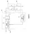
- the lamp driving systemcomprises an inverter 70 , a lamp set 80 and a balancing controller 50 .
- the inverter 70is provided with a power driving device 10 , a transformer T 1 and a PWM controller 30 .
- the lamp set 80is constituted by lamps Lp 1 and Lp 2
- the balancing controller 50is constituted by loads Zb, Zc and Zd.
- the power driving device 10is employed to convert a DC power Vin into an AC power which is stepped up by the transformer T 1 and then provided for the lamp set 80 .
- the PWM controller 30controls the power driving device in response to a feedback signal generated from the lamp set 80 .
- the balancing controller 50is used to regulate currents flowing through the lamps Lp 1 and Lp 2 to be substantially the same.
- the loads Za, Zb, Zc and Zdcan be the combinations of resistors, capacitors, inductors, transistors or integrated circuits.
- the operation of the balancing controller 50is based upon the impedance regulation of the loads Zb, Zc and Zd for the purpose of balancing load currents.
- the impedance regulationcan be made in a linear or digital manner.
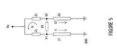
- FIG. 5is utilized to explain the operations of the balancing controller 50 of FIG. 4 .
- Iz(1 /Zd )( I 1 Z 1 ⁇ I 2 Z 2 ) (1)
- V 0I 1 ( Z 1 + Zc )+ IzZc (2)
- V 0I 2 ( Z 2 + Zc ) ⁇ IzZc (3)
- I 1 ( Z 1 + Zc )+ IzZcI 2 ( Z 2 + Zc ) ⁇ IzZc
- I 1 ( Z 1 + Zc )+2 IzZcI 2 ( Z 2 + Zc )
- I 1 ( Z 1 + Zc +2 Z 1 Zc/Zd )I 2 ( Z 2 + Zc +2 Z 2 Zc/Zd )
- I 1I 2 can conform to the requirement of current balancing if Zc/Zd is chosen to be( ⁇ 1 ⁇ 2).
- current balancingcan be achieved by means of impedance matching.
- the balancing controller 50 of FIG. 4can be replaced by the the combination of capacitors and an inductor as shown in FIG. 10 A.
- the balancing controller 50can be the combination of capacitors, an inductor and a resistor as shown in FIG. 10 B.
- other example of the balancing controller 50can be the combinations of inductors and a capacitor as shown in FIG. 10 C. Accordingly, those currents flowing through the lamps Lp 1 and Lp 2 can be substantially the same when the ratio Zc/Zd is ( ⁇ 1 ⁇ 2).
- the equivalent impedance ratio Zc/Zdis properly designed to be a negative ratio, the current difference between the lamps can be effectively reduced.
- I 1 ( Z 1 + Zc +2 Z 1 Zc/Zd )I 2 ( Z 2 + Zc +2 Z 2 Zc/Zd )
- I 1 / I 2( Z 2 + Zc +2 Z 2 Zc/Zd )/( Z 1 + Zc +2 Z 1 Zc/Zd )
- the current error (I 1 -I 2 )/I 1can be reduced by 1% (without taking phase into account).
- current difference between the lampscan be effectively reduced as long as the equivalent impedance ratio Zc/Zd is negative.
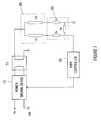
- FIG. 6the second preferred embodiment of a lamp driving system in accordance with the present invention is schematically depicted.
- the circuit of FIG. 6is similar to that of FIG. 5, but having difference in current feedback signals provided for the PWM controller 30 .
- the feedback signal provided for the PWM controller 30is responsive to the current flowing through the lamp Lp 1
- the feedback signal provided for the PWM controller 30is responsive to the currents flowing through the lamps Lp 1 and Lp 2 .
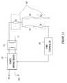
- the third preferred embodiment of a lamp driving system in accordance with the present inventionis schematically depicted.
- the balancing controller 50is connected between the lamp set 80 and the PWM controller 30 .
- the fourth preferred embodiment of a lamp driving system in accordance with the present inventionis schematically depicted.
- a load choke 60is employed to regulate load balance of whole circuitry.
- the balancing controller 50 acomprises loads Zp 1 , Zp 2 , . . . , Zpm and the load choke 60 .
- the impedance relation of the load choke 60 and the loads Zp 1 , Zp 2 , . . . , Zpmcan be found upon the formulae as mentioned above.
- FIG. 9the fifth preferred embodiment of a lamp driving system in accordance with the present invention is schematically depicted.
- a load choke 60 of Figurefunctions as that of FIG. 6 .
- the fifth preferred embodimentcould be applied to an inverter provided with multiple transformers.
- FIG. 11the sixth preferred embodiment of a lamp driving system in accordance with the present invention is schematically depicted.
- the circuit of FIG. 11is similar to that of FIG. 4 except that the balancing controller 50 in FIG. 4 is replaced by the balancing controller 50 ′ in FIG. 11 by performing a ⁇ -Y transform.
- the ⁇ -circuit consisting of loads Zb, Zc and Zd in the balancing controller 50 of FIG. 4is transformed to a Y-circuit consisting of loads Zb, Zc and Zd in the balancing controller 50 ′ of FIG. 11 by applying a ⁇ -Y transform.
- the Load Zeis seriesly connected to the load Za while the loads Zf and Zg are seriesly connected to the lamps Lp 1 and Lp 2 respectively.
- the load Zfis substantially the same as load Zg, and the impedance ratio of the load Ze to the load Zf is preferably equal to ( ⁇ 1 ⁇ 2).
- the equivalent Y-type balancing controller 50 ′exhibits the same operation characteristics as the ⁇ -type balancing controller 50 .
- the balancing controller 50 ′preferably comprises the combination of capacitors and an inductor as shown in FIG. 13 A.
- the balancing controller 50 of the second preferred embodiment in FIG. 6may also be replaced by the balancing controller 50 ′ in FIG. 7, the description of which is omitted for simplification.
- the seventh preferred embodiment of a lamp driving system in accordance with the present inventionis schematically depicted.
- the balancing controller 50 ′is provided at the high-voltage end of the lamp set.
- the balancing controller 50 ′may also be provided at the low-voltage end of the lamp set to form the configuration as show in FIG. 12 with the loads Zf and Zg seriesly coupled to the low voltage ends of the lamps Lp 1 and Lp 2 respectively.
- the balancing controller 50 ′ of the seventh preferred embodimentpreferably comprises the combination of capacitors and an inductor as shown in FIG. 13 B.
- the balancing controller 50 ′′ of the eighth preferred embodimentcomprises loadx Ze, Zp 1 , Zp 2 , . . . , Zpn, wherein impedances of the loads Zp 1 , Zp 2 , . . . , Zpn are substantially the same and the impedance ratio of the load Ze to the load Zp 1 is negative, for balancing the current passing through each of the lamps Lp 1 , Lp 2 , . . . , Lpn.
- the load Zeis a capacitor and the loads Zp 1 , Zp 2 , . . .
- Zpnare inductors. Although the loads Zp 1 , Zp 2 , . . . , Zpn shown are coupled to the high-voltage end of the lamps Lp 1 , Lp 2 , . . . , Lpn; however, similar to the seventh preferred embodiment of FIG. 12, the loads may also be coupled to the low-voltage end of the lamp set in an application having more lamps.
Landscapes
- Engineering & Computer Science (AREA)
- Power Engineering (AREA)
- Circuit Arrangements For Discharge Lamps (AREA)
Abstract
Description
1. Field of the Invention
The present invention generally relates to a lamp driving system. More particularly, the present invention relates to a multi-lamp driving system in the application of the backlight module of a liquid crystal display.
2. Description of the Related Art
A discharge lamp used to backlight an LCD panel such as a cold cathode fluorescent lamp (CCFL) has terminal voltage characteristics that vary depending upon the immediate history and the frequency of a stimulus (AC signal) applied to the lamp. Until the CCFL is struck or ignited, the lamp will not conduct a current with an applied terminal voltage that is less than the strike voltage, e.g., the terminal voltage must be equal to or greater than 1500 Volts. Once an electrical arc is struck inside the CCFL, the terminal voltage may fall to a run voltage that is approximately ⅓ the value of the strike voltage over a relatively wide range of input currents. For example, the run voltage could be 500 Volts over a range of 500 microAmps to 6 milliAmps for a CCFL that has a strike voltage of 1,500 Volt. Usually, the CCFL is driven by AC signals having frequencies that range from 30 KiloHertz to 100 KiloHertz.
The discharge lamp exhibits a negative impedance characteristic that the equivalent impedance is decreased upon an increase of input power. Therefore, a circuit for providing the lamp with power, such as an inverter, should be configured with a controllable alternating current power supply and a feedback loop for monitoring the current flowing through the lamp to ensure stable operation and make load regulation as well.
Referring to FIG. 1, a conventional lamp driving system is schematically depicted. The system of FIG. 1 has only one feedback loop used for controlling the total current flowing through a lamp or lamps, but not used for controlling or balancing those currents flowing througheach lamp. If the current through one lamp is significantly larger than others, the lamp will be shortened in lifetime and the LCD panel will be degraded in brightness uniformity.
Referring to FIG. 2, another conventional lamp driving system is schematically depicted. However, the system of FIG. 2 is configured with two sets of control circuits resulting in an increase of cost and space.
Referring to FIG. 3, further another conventional driving system is schematically depicted. However, the system of FIG. 3 has two transformers also resulting in an increase of cost and space. Moreover, the transformers are configured with secondary coils connected in parallel to be adverse to high-voltage processing.
It is therefore an object of the present invention to provide a lamp driving system for controlling the balance of currents at load end, which can be extensively applied to a system with single feedback loop and multiple loads.
It is another object of the present invention to provide a lamp driving system with cost efficiency, compact space and simplified manufacturing.
It is further another object of the present invention to provide a lamp driving system for controlling the balance of currents precisely.
To achieve aforementioned objects, the present invention provides a multi-lamp driving system comprising: an inverter for generating an AC power, a lamp set having a first lamp and a second lamp, and a balancing controller coupled with the inverter and the lamp set for balancing currents flowing through the first lamp and the second lamp. The balancing controller comprises: a first load coupled with the first lamp and the inverter, a second load coupled with the second lamp and the inverter, and a third load coupled with the first load and the second load, wherein the impedance ratio of the third load to the first load is negative.
Moreover, the present invention provides a multi-lamp driving system comprising: an inverter for generating an AC power, a lamp set having a plurality of lamps, and a balancing controller coupled with the lamp set and the inverter for balancing currents flowing through the plurality of lamps. The balancing controller comprises: a plurality of loads, each of which is coupled with one of the plurality of lamps and the inverter; and a load choke coupled with the plurality of loads to balance currents flowing through the plurality of lamps.
The following detailed description, given by way of examples and not intended to limit the invention to the embodiments described herein, will best be understood in conjunction with the accompanying drawings, in which:
FIG. 1 schematically depicts a conventional lamp driving system;
FIG. 2 schematically depicts another conventional lamp driving system;
FIG. 3 schematically depicts further another conventional lamp driving system;
FIG. 4 schematically depicts the first preferred embodiment of a lamp driving system in accordance with the present invention;
FIG. 5 schematically depicts the balancing controller of FIG. 4;
FIG. 6 schematically depicts the second preferred embodiment of a lamp driving system in accordance with the present invention;
FIG. 7 schematically depicts the third preferred embodiment of a lamp driving system in accordance with the present invention;
FIG. 8 schematically depicts the fourth preferred embodiment of a lamp driving system in accordance with the present invention;
FIG. 9 schematically depicts the fifth preferred embodiment of a lamp driving system in accordance with the present invention;
FIGS. 10A to10C schematically depict various circuit configurations of the balancing controller according to the present invention;
FIG. 11 schematically depicts the sixth preferred embodiment of a lamp driving system in accordance with the present invention;
FIG. 12 schematically depicts the seventh preferred embodiment of a lamp driving system in accordance with the present invention;
FIGS. 13A to13B schematically depict two embodiments with their balancing controllers provided at the high-voltage end and low-voltage end respectively; and
FIG. 14 schematically depicts the eighth preferred embodiment of a lamp driving system in accordance with the present invention.
Referring to FIG. 4, the first preferred embodiment of a lamp driving system in accordance with the present invention is schematically depicted. In FIG. 4, the lamp driving system comprises aninverter 70, a lamp set80 and abalancing controller 50. Theinverter 70 is provided with apower driving device 10, a transformer T1 and aPWM controller 30. Thelamp set 80 is constituted by lamps Lp1 and Lp2, and thebalancing controller 50 is constituted by loads Zb, Zc and Zd.
Thepower driving device 10 is employed to convert a DC power Vin into an AC power which is stepped up by the transformer T1 and then provided for thelamp set 80. ThePWM controller 30 controls the power driving device in response to a feedback signal generated from thelamp set 80. According to the first preferred embodiment of the present invention, thebalancing controller 50 is used to regulate currents flowing through the lamps Lp1 and Lp2 to be substantially the same. The loads Za, Zb, Zc and Zd can be the combinations of resistors, capacitors, inductors, transistors or integrated circuits. The operation of thebalancing controller 50 is based upon the impedance regulation of the loads Zb, Zc and Zd for the purpose of balancing load currents. The impedance regulation can be made in a linear or digital manner.
FIG. 5 is utilized to explain the operations of thebalancing controller 50 of FIG.4.
Assume that Za=0, Zb=Zc, Lp1=Z1 and Lp2=Z2, V12=I1Z1−I2Z2, and
From equations (2) and (3),
2Zc/Zd=(−1)
Thus, I1=I2 can conform to the requirement of current balancing if Zc/Zd is chosen to be(−½).
If capacitance C and inductance L are utilized to the loads Zc and Zd respectively, at an operating frequency ω,
In other words, the purpose of current balancing can be attained if 1/LC=ω2/2.
According to the present invention, current balancing can be achieved by means of impedance matching. In addition, the balancingcontroller 50 of FIG. 4 can be replaced by the the combination of capacitors and an inductor as shown in FIG.10A. Moreover, the balancingcontroller 50 can be the combination of capacitors, an inductor and a resistor as shown in FIG.10B. Furthermore, other example of the balancingcontroller 50 can be the combinations of inductors and a capacitor as shown in FIG.10C. Accordingly, those currents flowing through the lamps Lp1 and Lp2 can be substantially the same when the ratio Zc/Zd is (−½).
Moreover, as long as the equivalent impedance ratio Zc/Zd is properly designed to be a negative ratio, the current difference between the lamps can be effectively reduced. As an example,
Assume Z1=10, Z2=11, Zc=−10j and Zd=15j (Zc/Zd=−1/1.5),
Accordingly, the current error (I1-I2)/I1 can be reduced by 1% (without taking phase into account). Thus, current difference between the lamps can be effectively reduced as long as the equivalent impedance ratio Zc/Zd is negative.
Referring to FIG. 6, the second preferred embodiment of a lamp driving system in accordance with the present invention is schematically depicted. The circuit of FIG. 6 is similar to that of FIG. 5, but having difference in current feedback signals provided for thePWM controller 30. In FIG. 5, the feedback signal provided for thePWM controller 30 is responsive to the current flowing through the lamp Lp1, but the feedback signal provided for thePWM controller 30 is responsive to the currents flowing through the lamps Lp1 and Lp2.
Referring to FIG. 7, the third preferred embodiment of a lamp driving system in accordance with the present invention is schematically depicted. In this embodiment, the balancingcontroller 50 is connected between the lamp set80 and thePWM controller 30.
Referring to FIG. 8, the fourth preferred embodiment of a lamp driving system in accordance with the present invention is schematically depicted. In this case, aload choke 60 is employed to regulate load balance of whole circuitry. According to the fourth embodiment of the present invention, the balancingcontroller 50acomprises loads Zp1, Zp2, . . . , Zpm and theload choke 60. The impedance relation of theload choke 60 and the loads Zp1, Zp2, . . . , Zpm can be found upon the formulae as mentioned above.
Referring to FIG. 9, the fifth preferred embodiment of a lamp driving system in accordance with the present invention is schematically depicted. Aload choke 60 of Figure functions as that of FIG.6. However, the fifth preferred embodiment could be applied to an inverter provided with multiple transformers.
Referring to FIG. 11, the sixth preferred embodiment of a lamp driving system in accordance with the present invention is schematically depicted. The circuit of FIG. 11 is similar to that of FIG. 4 except that the balancingcontroller 50 in FIG. 4 is replaced by the balancingcontroller 50′ in FIG. 11 by performing a Δ-Y transform. Specifically, the Δ-circuit consisting of loads Zb, Zc and Zd in the balancingcontroller 50 of FIG. 4 is transformed to a Y-circuit consisting of loads Zb, Zc and Zd in the balancingcontroller 50′ of FIG. 11 by applying a Δ-Y transform. The Load Ze is seriesly connected to the load Za while the loads Zf and Zg are seriesly connected to the lamps Lp1 and Lp2 respectively.
Recalling that, as was mentioned earlier, it is assumed Za=Zc, Zc/Zd and Zb/Zd are both negative, and preferably Zc/Zd=Zb/Zd=(−½) in the embodiment of FIG. 4, the values of loads Ze, Zf and Zg in the equivalent circuit can therefore be derived from the following equations:
Accordingly, the load Zf is substantially the same as load Zg, and the impedance ratio of the load Ze to the load Zf is preferably equal to (−½). Thereby, the equivalent Y-type balancing controller 50′ exhibits the same operation characteristics as the Δ-type balancing controller 50. Accordingly to the sixth preferred embodiment of the invention, the balancingcontroller 50′ preferably comprises the combination of capacitors and an inductor as shown in FIG.13A.
Similarly, the balancingcontroller 50 of the second preferred embodiment in FIG. 6 may also be replaced by the balancingcontroller 50′ in FIG. 7, the description of which is omitted for simplification.
Referring to FIG. 12, the seventh preferred embodiment of a lamp driving system in accordance with the present invention is schematically depicted. In the lamp driving system of the sixth preferred embodiment in FIG. 11, the balancingcontroller 50′ is provided at the high-voltage end of the lamp set. However, according to the seventh preferred embodiment of the invention, the balancingcontroller 50′ may also be provided at the low-voltage end of the lamp set to form the configuration as show in FIG. 12 with the loads Zf and Zg seriesly coupled to the low voltage ends of the lamps Lp1 and Lp2 respectively. The balancingcontroller 50′ of the seventh preferred embodiment preferably comprises the combination of capacitors and an inductor as shown in FIG.13B.
Referring to FIG. 12, the eighth preferred embodiment of a lamp driving system in accordance with the present invention is schematically depicted. The balancingcontroller 50″ of the eighth preferred embodiment comprises loadx Ze, Zp1, Zp2, . . . , Zpn, wherein impedances of the loads Zp1, Zp2, . . . , Zpn are substantially the same and the impedance ratio of the load Ze to the load Zp1 is negative, for balancing the current passing through each of the lamps Lp1, Lp2, . . . , Lpn. For example, the load Ze is a capacitor and the loads Zp1, Zp2, . . . , Zpn are inductors. Although the loads Zp1, Zp2, . . . , Zpn shown are coupled to the high-voltage end of the lamps Lp1, Lp2, . . . , Lpn; however, similar to the seventh preferred embodiment of FIG. 12, the loads may also be coupled to the low-voltage end of the lamp set in an application having more lamps.
While the invention has been described with reference to various illustrative embodiments, the description is not intended to be construed in a limiting sense. Various modifications of the illustrative embodiments, as well as other embodiments of the invention, will be apparent to those person skilled in the art upon reference to this description. It is therefore contemplated that the appended claims will cover any such modifications or embodiments as may fall within the scope of the invention defined by the following claims and their equivalents.
Claims (31)
1. A multi-lamp driving system for driving a lamp set having a first lamp and a second lamp, said system comprising:
an inverter for generating an AC power; and
a balancing controller electrically coupled with said inverter and said lamp set for balancing currents flowing through said first lamp and said second lamp, said balancing controller comprising:
a first load electrically coupled with said first lamp and said inverter;
a second load electrically coupled with said second lamp and said inverter, said second load having an impedance substantially the same as that of said first load; and
a third load electrically coupled with said first load and said second load, wherein the impedance ratio of said third load to said first load is negative.
2. The system as claimed inclaim 1 , wherein said inverter comprises:
a power driving device for converting a DC power to said AC power;
a transformer electrically coupled with said balancing controller and said power driving device; and
a PWM controller electrically coupled with said lamp set and said power driving device for controlling said power driving device in response to a feedback signal generated from said lamp set.
3. The system as claimed inclaim 2 , wherein said PWM controller is electrically coupled to said first lamp.
4. The system as claimed inclaim 2 , wherein said PWM controller is electrically coupled with said first lamp and said second lamp.
5. The system as claimed inclaim 1 , wherein said first load and said second load are capacitive loads, said third load is an inductive load.
6. The system as claimed inclaim 5 , wherein said third load is a combination of a resistor, an inductor and capacitors.
7. The system as claimed inclaim 1 , wherein the impedance ratio of said third load to said first load is substantially equal to −2, preferably.
8. The system as claimed inclaim 1 , wherein said inverter comprises:
a power driving device for converting a DC power to said AC power;
a transformer electrically coupled with said lamp set and said power driving device; and
a PWM controller electrically coupled with said balancing controller and said power driving device for controlling said power driving device in response to a feedback signal generated from said balancing controller.
9. The system as claimed inclaim 8 , wherein said PWM controller coupled to said first load.
10. The system as claimed inclaim 8 , wherein said PWM controller is electrically coupled with said first load and said second load.
11. The system as claimed inclaim 8 , said first load and said second load are capacitive loads, said third load is an inductive load.
12. The system as claimed inclaim 11 , wherein said third load is a combination of a resistor, an inductor and capacitors.
13. A multi-lamp driving system for driving a lamp set having a plurality of lamps, said system comprising:
an inverter for generating an AC power;
a balancing controller electrically coupled with said lamp set and said inverter for balancing currents flowing through said plurality of lamps, said balancing controller comprising:
a plurality of loads, each of which is electrically coupled with one of said plurality of lamps and said inverter and each of which has substantially the same impedance; and
a load choke electrically coupled with said plurality of loads to balance currents flowing through said plurality of lamps, wherein the impedance ratio of said load choke to each of said plurality of loads is negative.
14. The system as claimed inclaim 13 , wherein said plurality of loads are capacitive loads and said load choke is an inductive device.
15. The system as claimed inclaim 13 , wherein said inverter comprises:
a power driving device for converting a DC power to said AC power;
a transformer electrically coupled with said balancing controller and said power driving device; and
a PWM controller electrically coupled with said lamp set and said power driving device for controlling said power driving device in response to a feedback signal generated from said lamp set.
16. The system as claimed inclaim 15 , wherein said PWM controller is electrically coupled with one of said plurality of lamps.
17. The system as claimed inclaim 13 , wherein said inverter comprises:
a power driving device for converting a DC power to said AC power;
at least two transformers connected in parallel, said transformers being electrically coupled with said balancing controller and said power driving device, respectively; and
a PWM controller electrically coupled with said lamp set and said power driving device for controlling said power driving device in response to a feedback signal generated from said lamp set.
18. A multi-lamp driving system for driving a lamp set having a first lamp and a second lamp, said system comprising:
an inverter for generating an AC power; and
a balancing controller for balancing currents flowing through said first lamp and said second lamp, said balancing controller comprising a first load, a second load and a third load, one end of said first load being electrically coupled to one end of said second load and one end of said third load, the other end of said first load being electrically coupled to said inverter, the other end of said second load being electrically coupled to said first lamp, the other end of said third load being electrically coupled to said second lamp, said second load having an impedance substantially the same as that of said third load, and the impedance ratio of said first load to said second load is negative.
19. The system as claimed inclaim 18 , wherein said inverter comprises:
a power driving device for converting a DC power to said AC power;
a transformer electrically coupled with said balancing controller and said power driving device; and
a PWM controller electrically coupled with said lamp set and said power driving device for controlling said power driving device in response to a feedback signal generated from said lamp set.
20. The system as claimed inclaim 19 , wherein said PWM controller is electrically coupled to said first lamp.
21. The system as claimed inclaim 19 , wherein said PWM controller is electrically coupled with said first lamp and said second lamp.
22. The system as claimed inclaim 18 , wherein said first load is a capacitive load, and said second load and said third load are inductive loads.
23. The system as claimed inclaim 18 , wherein the impedance ratio of said second load to said first load is substantially equal to −2, preferably.
24. A multi-lamp driving system for driving a lamp set having a first lamp and a second lamp, said system comprising:
an inverter for generating an AC power; and
a balancing controller for balancing currents flowing through said first lamp and said second lamp, said balancing controller comprising a first load, a second load and a third load, said first load being electrically coupled between said inverter and one end of said lamp set, said second load being electrically coupled between said inverter and the other end of said first lamp, said third load being electrically coupled between said inverter and the other end of said second lamp, said second load having an impedance substantially the same as that of said third load, and the impedance ratio of said first load to said second load is negative.
25. The system as claimed inclaim 24 , wherein said inverter comprises:
a power driving device for converting a DC power to said AC power;
a transformer electrically coupled with said balancing controller and said power driving device; and
a PWM controller electrically coupled with said lamp set and said power driving device for controlling said power driving device in response to a feedback signal generated from said lamp set.
26. The system as claimed inclaim 25 , wherein said PWM controller is electrically coupled to said second load.
27. The system as claimed inclaim 25 , wherein said PWM controller is electrically coupled with said second load and said third load.
28. The system as claimed inclaim 24 , wherein said first load is a capacitive load, and said second load and said third load are inductive loads.
29. The system as claimed inclaim 24 , wherein the impedance ratio of said second load to said first load is substantially equal to −2, preferably.
30. A multi-lamp driving system for driving a lamp set having a plurality of lamps, said system comprising:
an inverter for generating an AC power; and
a balancing controller for balancing currents flowing through said first lamp and said second lamp, said balancing controller comprising a first load and a plurality of second loads;
wherein one end of said first load is electrically coupled to said inverter, the other end of said first load is electrically coupled to one end of each of said second loads, the other end of each of said second loads is electrically coupled to each of said lamps respectively, and the impedance ratio of said first load to said second load is negative.
31. A multi-lamp driving system for driving a lamp set having a plurality of lamps, said system comprising:
an inverter for generating an AC power; and
a balancing controller for balancing currents flowing through said first lamp and said second lamp, said balancing controller comprising a first load and a plurality of second loads;
wherein said first load is electrically coupled between said inverter and one end of said lamp set, one end of each of said second loads is electrically couple to the other end of each of said lamps respectively, the other end of each of said second loads is electrically coupled to said inverter, and the impedance ratio of said first load to said second load is negative.
Applications Claiming Priority (2)
| Application Number | Priority Date | Filing Date | Title |
|---|---|---|---|
| TW090105249ATW478292B (en) | 2001-03-07 | 2001-03-07 | Multi-lamp driving system |
| TW90105249A | 2001-03-07 |
Publications (1)
| Publication Number | Publication Date |
|---|---|
| US6534934B1true US6534934B1 (en) | 2003-03-18 |
Family
ID=21677552
Family Applications (1)
| Application Number | Title | Priority Date | Filing Date |
|---|---|---|---|
| US09/929,340Expired - Fee RelatedUS6534934B1 (en) | 2001-03-07 | 2001-08-15 | Multi-lamp driving system |
Country Status (3)
| Country | Link |
|---|---|
| US (1) | US6534934B1 (en) |
| JP (1) | JP3588070B2 (en) |
| TW (1) | TW478292B (en) |
Cited By (55)
| Publication number | Priority date | Publication date | Assignee | Title |
|---|---|---|---|---|
| US20030227452A1 (en)* | 2002-06-07 | 2003-12-11 | Alexandru Hartular | Adaptive LCD power supply circuit |
| US20040000879A1 (en)* | 2002-04-12 | 2004-01-01 | Lee Sheng Tai | Circuit structure for driving a plurality of cold cathode fluorescent lamps |
| US20040155601A1 (en)* | 2003-02-06 | 2004-08-12 | Chin-Wen Chou | LCD back light panel lamp connecting structure |
| US20040207340A1 (en)* | 2003-04-11 | 2004-10-21 | Benq Corporation | Device and method for adjusting currents of lamp tubes |
| US20040257003A1 (en)* | 2003-06-23 | 2004-12-23 | Chang-Fa Hsieh | Lamp driving system |
| US20050062436A1 (en)* | 2003-09-09 | 2005-03-24 | Xiaoping Jin | Split phase inverters for CCFL backlight system |
| US20050093471A1 (en)* | 2003-10-06 | 2005-05-05 | Xiaoping Jin | Current sharing scheme for multiple CCF lamp operation |
| US20050093484A1 (en)* | 2003-10-21 | 2005-05-05 | Ball Newton E. | Systems and methods for fault protection in a balancing transformer |
| US20050099132A1 (en)* | 2003-11-06 | 2005-05-12 | Chia-Tse Yeh | Apparatus for driving a light tube and method therefor |
| US20050156540A1 (en)* | 2003-12-16 | 2005-07-21 | Ball Newton E. | Inverter with two switching stages for driving lamp |
| US20050190142A1 (en)* | 2004-02-09 | 2005-09-01 | Ferguson Bruce R. | Method and apparatus to control display brightness with ambient light correction |
| US20050225261A1 (en)* | 2004-04-07 | 2005-10-13 | Xiaoping Jin | Primary side current balancing scheme for multiple CCF lamp operation |
| US20050269976A1 (en)* | 2003-02-06 | 2005-12-08 | Zippy Technology Corp. | LCD back light panel lamp connecting structure |
| US20050269975A1 (en)* | 2003-02-06 | 2005-12-08 | Zippy Technology Corp. | LCD back light panel lamp connecting structure |
| US20050285548A1 (en)* | 2004-06-25 | 2005-12-29 | Moyer James C | Method and apparatus for driving an external electrode fluorescent lamp |
| US20060001386A1 (en)* | 2004-06-30 | 2006-01-05 | Lg.Philips Lcd Co., Ltd. | Backlight unit for liquid crystal display device |
| US20060071615A1 (en)* | 2004-10-01 | 2006-04-06 | Au Optronics Corporation | Floating drive circuit for cold cathode fluorescent lamp |
| US20060076907A1 (en)* | 2004-10-08 | 2006-04-13 | Chien-Chih Chen | Multi-phase multi-lamp driving system |
| US20060119293A1 (en)* | 2004-12-03 | 2006-06-08 | Chun-Kong Chan | Lamp load-sharing circuit |
| US20060119286A1 (en)* | 2004-12-06 | 2006-06-08 | Huang Shih-Chung | Lamp driving topology with current balancing scheme |
| US20060120109A1 (en)* | 2002-08-06 | 2006-06-08 | Yutaka Inoue | Inverter circuit, fluorescent bulb operating device, backlight device, and liquid crystal display device |
| US20060197466A1 (en)* | 2005-03-04 | 2006-09-07 | Samsung Electronics Co., Ltd. | Parallel drive cold cathode fluorescent lamp device |
| US20060220593A1 (en)* | 2005-03-31 | 2006-10-05 | Ball Newton E | Nested balancing topology for balancing current among multiple lamps |
| WO2006107305A1 (en)* | 2005-03-31 | 2006-10-12 | Microsemi Corporation | Zigzag topology for balancing current among multiple lamps |
| US20060273745A1 (en)* | 2005-06-07 | 2006-12-07 | Au Optronics Corporation | Current balancing circuit for a multi-lamp system |
| US20060284569A1 (en)* | 2005-06-16 | 2006-12-21 | Au Optronics Corporation | Balanced circuit for multi-LED driver |
| US20060290297A1 (en)* | 2005-06-24 | 2006-12-28 | Hon Hai Precision Industry Co., Ltd. | Device for driving light sources |
| US20070014130A1 (en)* | 2004-04-01 | 2007-01-18 | Chii-Fa Chiou | Full-bridge and half-bridge compatible driver timing schedule for direct drive backlight system |
| US20070018593A1 (en)* | 2005-07-22 | 2007-01-25 | Delta Electronics Inc. | Balanced current lamp module and multi-lamp circuit |
| US20070035258A1 (en)* | 2005-08-10 | 2007-02-15 | Chin-Der Wey | Lamp drive circuit |
| US20070085493A1 (en)* | 2005-10-19 | 2007-04-19 | Kuo Ching C | Lamp current balancing topologies |
| US20070097283A1 (en)* | 2005-10-28 | 2007-05-03 | Innolux Display Corp. | Backlight control circuit with dual input circuits |
| US20070114953A1 (en)* | 2005-11-24 | 2007-05-24 | Samsung Electro-Mechanics Co., Ltd. | Backlight assembly |
| US20070132398A1 (en)* | 2003-09-23 | 2007-06-14 | Microsemi Corporation | Optical and temperature feedbacks to control display brightness |
| US20070159115A1 (en)* | 2006-01-11 | 2007-07-12 | Kang Moon S | Apparatus for driving lamps and liquid crystal display having the same |
| WO2007093215A1 (en)* | 2006-02-14 | 2007-08-23 | Tte Germany Gmbh | Backlight system |
| US7268501B1 (en)* | 2006-07-12 | 2007-09-11 | Darfon Electronics Corp. | Multi-lamp driving circuit |
| US20080024075A1 (en)* | 2002-12-13 | 2008-01-31 | Microsemi Corporation | Apparatus and method for striking a fluorescent lamp |
| US20080067944A1 (en)* | 2006-09-18 | 2008-03-20 | Xiaojun Wang | Circuit structure for LCD backlight |
| EP1526762A3 (en)* | 2003-10-24 | 2008-04-09 | Masakazu Ushijima | Inverter circuit for surface light source system |
| US20080149810A1 (en)* | 2006-11-15 | 2008-06-26 | Mag-E Tech, Inc. | Lighting Configuration and Circuits |
| US7414371B1 (en) | 2005-11-21 | 2008-08-19 | Microsemi Corporation | Voltage regulation loop with variable gain control for inverter circuit |
| US20080203944A1 (en)* | 2007-02-26 | 2008-08-28 | Au Optronics Corporation | Lighting apparatus with current feedback |
| CN100443963C (en)* | 2005-10-26 | 2008-12-17 | 群康科技(深圳)有限公司 | Cold-cathode fluorescent lamp balance control circuit |
| US20090108771A1 (en)* | 2007-10-30 | 2009-04-30 | Shwang-Shi Bai | Driving system for electronic device and current balancing circuit thereof |
| US7569998B2 (en) | 2006-07-06 | 2009-08-04 | Microsemi Corporation | Striking and open lamp regulation for CCFL controller |
| US7755595B2 (en) | 2004-06-07 | 2010-07-13 | Microsemi Corporation | Dual-slope brightness control for transflective displays |
| US7977888B2 (en) | 2003-10-06 | 2011-07-12 | Microsemi Corporation | Direct coupled balancer drive for floating lamp structure |
| US20110234479A1 (en)* | 2010-03-23 | 2011-09-29 | Duyeon Han | Backlight Unit and Display Apparatus Having the Same |
| US20110298388A1 (en)* | 2008-02-14 | 2011-12-08 | Au Optronics Corporation | Light driver circuit device and backlight device |
| US8093839B2 (en) | 2008-11-20 | 2012-01-10 | Microsemi Corporation | Method and apparatus for driving CCFL at low burst duty cycle rates |
| US8598795B2 (en) | 2011-05-03 | 2013-12-03 | Microsemi Corporation | High efficiency LED driving method |
| US8754581B2 (en) | 2011-05-03 | 2014-06-17 | Microsemi Corporation | High efficiency LED driving method for odd number of LED strings |
| US9030119B2 (en) | 2010-07-19 | 2015-05-12 | Microsemi Corporation | LED string driver arrangement with non-dissipative current balancer |
| US9547348B2 (en) | 2013-05-10 | 2017-01-17 | Walter Kidde Portable Equipment Inc. | Reactive power supply |
Families Citing this family (8)
| Publication number | Priority date | Publication date | Assignee | Title |
|---|---|---|---|---|
| JP2004335443A (en) | 2003-02-10 | 2004-11-25 | Masakazu Ushijima | Inverter circuit for discharge tube for multiple lamp lighting, and surface light source system |
| US7589478B2 (en) | 2003-02-10 | 2009-09-15 | Masakazu Ushijima | Inverter circuit for discharge lamps for multi-lamp lighting and surface light source system |
| TWI223287B (en) | 2003-07-25 | 2004-11-01 | Darfon Electronics Corp | Transformer and multi-tube system applying the same |
| JP4101228B2 (en) | 2004-03-19 | 2008-06-18 | 昌和 牛嶋 | Discharge tube parallel lighting system for surface light source |
| JP2005353572A (en) | 2004-05-13 | 2005-12-22 | Sony Corp | Fluorescence tube driving device, and liquid crystal display device |
| JP2006049030A (en)* | 2004-08-03 | 2006-02-16 | Sanaa Electronics Kk | Lighting circuit for discharge lamp |
| US7042171B1 (en) | 2004-11-26 | 2006-05-09 | Hsiu-Ying Li | Multiple-CCFL parallel driving circuit and the associated current balancing control method for liquid crystal display |
| TWI404457B (en)* | 2009-09-18 | 2013-08-01 | Innolux Corp | Lamp driving circuit |
Citations (9)
| Publication number | Priority date | Publication date | Assignee | Title |
|---|---|---|---|---|
| US5063331A (en)* | 1991-01-04 | 1991-11-05 | North American Philips Corporation | High frequency oscillator-inverter circuit for discharge lamps |
| US5424614A (en)* | 1994-03-03 | 1995-06-13 | Usi Lighting, Inc. | Modified half-bridge parallel-loaded series resonant converter topology for electronic ballast |
| US5438243A (en)* | 1993-12-13 | 1995-08-01 | Kong; Oin | Electronic ballast for instant start gas discharge lamps |
| US6060843A (en)* | 1996-01-26 | 2000-05-09 | Tridonic Bauelemente Gmbh | Method and control circuit for regulation of the operational characteristics of gas discharge lamps |
| US6137239A (en)* | 1999-08-11 | 2000-10-24 | Energy Savings, Inc. | Electronic ballast with selective load control |
| US6181079B1 (en)* | 1999-12-20 | 2001-01-30 | Philips Electronics North America Corporation | High power electronic ballast with an integrated magnetic component |
| US6236168B1 (en)* | 1998-04-15 | 2001-05-22 | Electro-Mag International, Inc. | Ballast instant start circuit |
| US6366029B1 (en)* | 2000-05-31 | 2002-04-02 | Keith Billings | Lamp ballast for reducing interference current |
| US6420839B1 (en)* | 2001-01-19 | 2002-07-16 | Ambit Microsystems Corp. | Power supply system for multiple loads and driving system for multiple lamps |
- 2001
- 2001-03-07TWTW090105249Apatent/TW478292B/ennot_activeIP Right Cessation
- 2001-08-15USUS09/929,340patent/US6534934B1/ennot_activeExpired - Fee Related
- 2001-09-06JPJP2001270973Apatent/JP3588070B2/ennot_activeExpired - Fee Related
Patent Citations (9)
| Publication number | Priority date | Publication date | Assignee | Title |
|---|---|---|---|---|
| US5063331A (en)* | 1991-01-04 | 1991-11-05 | North American Philips Corporation | High frequency oscillator-inverter circuit for discharge lamps |
| US5438243A (en)* | 1993-12-13 | 1995-08-01 | Kong; Oin | Electronic ballast for instant start gas discharge lamps |
| US5424614A (en)* | 1994-03-03 | 1995-06-13 | Usi Lighting, Inc. | Modified half-bridge parallel-loaded series resonant converter topology for electronic ballast |
| US6060843A (en)* | 1996-01-26 | 2000-05-09 | Tridonic Bauelemente Gmbh | Method and control circuit for regulation of the operational characteristics of gas discharge lamps |
| US6236168B1 (en)* | 1998-04-15 | 2001-05-22 | Electro-Mag International, Inc. | Ballast instant start circuit |
| US6137239A (en)* | 1999-08-11 | 2000-10-24 | Energy Savings, Inc. | Electronic ballast with selective load control |
| US6181079B1 (en)* | 1999-12-20 | 2001-01-30 | Philips Electronics North America Corporation | High power electronic ballast with an integrated magnetic component |
| US6366029B1 (en)* | 2000-05-31 | 2002-04-02 | Keith Billings | Lamp ballast for reducing interference current |
| US6420839B1 (en)* | 2001-01-19 | 2002-07-16 | Ambit Microsystems Corp. | Power supply system for multiple loads and driving system for multiple lamps |
Cited By (141)
| Publication number | Priority date | Publication date | Assignee | Title |
|---|---|---|---|---|
| US20080211305A1 (en)* | 2002-04-12 | 2008-09-04 | O2Micro International Limited | Circuit structure for driving a plurality of cold cathode fluorescent lamps |
| US20040000879A1 (en)* | 2002-04-12 | 2004-01-01 | Lee Sheng Tai | Circuit structure for driving a plurality of cold cathode fluorescent lamps |
| US7190123B2 (en)* | 2002-04-12 | 2007-03-13 | O2Micro International Limited | Circuit structure for driving a plurality of cold cathode fluorescent lamps |
| US6781325B2 (en)* | 2002-04-12 | 2004-08-24 | O2Micro International Limited | Circuit structure for driving a plurality of cold cathode fluorescent lamps |
| US7345431B2 (en)* | 2002-04-12 | 2008-03-18 | O2Micro International Limited | Circuit structure for driving a plurality of cold cathode flourescent lamps |
| US20070152608A1 (en)* | 2002-04-12 | 2007-07-05 | O2Micro International Limited | Circuit Structure for Driving a Plurality of Cold Cathode Flourescent Lamps |
| US20050023998A1 (en)* | 2002-04-12 | 2005-02-03 | Lee Sheng Tai | Circuit structure for driving a plurality of cold cathode fluorescent lamps |
| US7812546B2 (en)* | 2002-04-12 | 2010-10-12 | O2Micro International Limited | Circuit structure for driving a plurality of cold cathode fluorescent lamps |
| US20030227452A1 (en)* | 2002-06-07 | 2003-12-11 | Alexandru Hartular | Adaptive LCD power supply circuit |
| EP1542347A4 (en)* | 2002-08-06 | 2007-12-05 | Sharp Kk | Inverter circuit, fluorescent bulb operating device, backlight device, and liquid crystal display device |
| US20060120109A1 (en)* | 2002-08-06 | 2006-06-08 | Yutaka Inoue | Inverter circuit, fluorescent bulb operating device, backlight device, and liquid crystal display device |
| US7936136B2 (en) | 2002-08-06 | 2011-05-03 | Sharp Kabushiki Kaisha | Inverter circuit, fluorescent tube lighting apparatus, backlight apparatus, and liquid crystal display |
| US7791286B2 (en) | 2002-08-06 | 2010-09-07 | Sharp Kabushiki Kaisha | Inverter circuit, fluorescent tube lighting apparatus, backlight apparatus, and liquid crystal display |
| US7777431B2 (en) | 2002-08-06 | 2010-08-17 | Sharp Kabushiki Kaisha | Inverter circuit, fluorescent bulb operating device, backlight device, and liquid crystal display device |
| US7786681B2 (en) | 2002-08-06 | 2010-08-31 | Sharp Kabushiki Kaisha | Inverter circuit, fluorescent tube lighting apparatus, backlight apparatus, and liquid crystal display |
| US20080012500A1 (en)* | 2002-08-06 | 2008-01-17 | Yutaka Inoue | Inverter circuit, fluorescent tube lighting apparatus, backlight apparatus, and liquid crystal display |
| US20080067958A1 (en)* | 2002-08-06 | 2008-03-20 | Yutaka Inoue | Inverter circuit, fluorescent tube lighting apparatus, backlight apparatus, and liquid crystal display |
| US20080042967A1 (en)* | 2002-08-06 | 2008-02-21 | Yutaka Inoue | Inverter circuit, fluorescent tube lighting apparatus, backlight apparatus, and liquid crystal display |
| US7411360B2 (en) | 2002-12-13 | 2008-08-12 | Microsemi Corporation | Apparatus and method for striking a fluorescent lamp |
| US20080024075A1 (en)* | 2002-12-13 | 2008-01-31 | Microsemi Corporation | Apparatus and method for striking a fluorescent lamp |
| US7436133B2 (en) | 2003-02-06 | 2008-10-14 | Zippy Technology Corp. | LCD back light panel lamp connecting structure |
| US20050269976A1 (en)* | 2003-02-06 | 2005-12-08 | Zippy Technology Corp. | LCD back light panel lamp connecting structure |
| US6949890B2 (en)* | 2003-02-06 | 2005-09-27 | Zippy Technology Corp. | LCD back light panel lamp connecting structure |
| US20040155601A1 (en)* | 2003-02-06 | 2004-08-12 | Chin-Wen Chou | LCD back light panel lamp connecting structure |
| US20050269975A1 (en)* | 2003-02-06 | 2005-12-08 | Zippy Technology Corp. | LCD back light panel lamp connecting structure |
| US7479745B2 (en) | 2003-02-06 | 2009-01-20 | Zippy Technology Corp. | LCD back light panel lamp connecting structure |
| US6998797B2 (en)* | 2003-04-11 | 2006-02-14 | Benq Corporation | Device and method for adjusting currents of lamp tubes |
| US20040207340A1 (en)* | 2003-04-11 | 2004-10-21 | Benq Corporation | Device and method for adjusting currents of lamp tubes |
| US20040257003A1 (en)* | 2003-06-23 | 2004-12-23 | Chang-Fa Hsieh | Lamp driving system |
| US7075248B2 (en)* | 2003-06-23 | 2006-07-11 | Benq Corporation | Lamp driving system |
| US20070145911A1 (en)* | 2003-09-09 | 2007-06-28 | Microsemi Corporation | Split phase inverters for ccfl backlight system |
| US20050062436A1 (en)* | 2003-09-09 | 2005-03-24 | Xiaoping Jin | Split phase inverters for CCFL backlight system |
| US7952298B2 (en) | 2003-09-09 | 2011-05-31 | Microsemi Corporation | Split phase inverters for CCFL backlight system |
| US7187139B2 (en) | 2003-09-09 | 2007-03-06 | Microsemi Corporation | Split phase inverters for CCFL backlight system |
| US20090206767A1 (en)* | 2003-09-09 | 2009-08-20 | Microsemi Corporation | Split phase inverters for ccfl backlight system |
| US7525255B2 (en) | 2003-09-09 | 2009-04-28 | Microsemi Corporation | Split phase inverters for CCFL backlight system |
| US20070132398A1 (en)* | 2003-09-23 | 2007-06-14 | Microsemi Corporation | Optical and temperature feedbacks to control display brightness |
| US7391172B2 (en) | 2003-09-23 | 2008-06-24 | Microsemi Corporation | Optical and temperature feedbacks to control display brightness |
| US7990072B2 (en) | 2003-10-06 | 2011-08-02 | Microsemi Corporation | Balancing arrangement with reduced amount of balancing transformers |
| US7977888B2 (en) | 2003-10-06 | 2011-07-12 | Microsemi Corporation | Direct coupled balancer drive for floating lamp structure |
| US8008867B2 (en) | 2003-10-06 | 2011-08-30 | Microsemi Corporation | Arrangement suitable for driving floating CCFL based backlight |
| US20090267521A1 (en)* | 2003-10-06 | 2009-10-29 | Microsemi Corporation | Balancing transformers for multi-lamp operation |
| US7560875B2 (en) | 2003-10-06 | 2009-07-14 | Microsemi Corporation | Balancing transformers for multi-lamp operation |
| US7242147B2 (en) | 2003-10-06 | 2007-07-10 | Microsemi Corporation | Current sharing scheme for multiple CCF lamp operation |
| US7294971B2 (en) | 2003-10-06 | 2007-11-13 | Microsemi Corporation | Balancing transformers for ring balancer |
| US8222836B2 (en) | 2003-10-06 | 2012-07-17 | Microsemi Corporation | Balancing transformers for multi-lamp operation |
| US20050093472A1 (en)* | 2003-10-06 | 2005-05-05 | Xiaoping Jin | Balancing transformers for ring balancer |
| US20110181204A1 (en)* | 2003-10-06 | 2011-07-28 | Microsemi Corporation | Balancing transformers for multi-lamp operation |
| US20050093471A1 (en)* | 2003-10-06 | 2005-05-05 | Xiaoping Jin | Current sharing scheme for multiple CCF lamp operation |
| US7932683B2 (en) | 2003-10-06 | 2011-04-26 | Microsemi Corporation | Balancing transformers for multi-lamp operation |
| US7279851B2 (en) | 2003-10-21 | 2007-10-09 | Microsemi Corporation | Systems and methods for fault protection in a balancing transformer |
| US7250726B2 (en) | 2003-10-21 | 2007-07-31 | Microsemi Corporation | Systems and methods for a transformer configuration with a tree topology for current balancing in gas discharge lamps |
| US20050093484A1 (en)* | 2003-10-21 | 2005-05-05 | Ball Newton E. | Systems and methods for fault protection in a balancing transformer |
| CN1610474B (en)* | 2003-10-24 | 2011-03-30 | 牛岛昌和 | Inverter circuit for discharge tube |
| EP1526762A3 (en)* | 2003-10-24 | 2008-04-09 | Masakazu Ushijima | Inverter circuit for surface light source system |
| US20050099132A1 (en)* | 2003-11-06 | 2005-05-12 | Chia-Tse Yeh | Apparatus for driving a light tube and method therefor |
| US7015659B2 (en)* | 2003-11-06 | 2006-03-21 | Benq Corporation | Apparatus for driving a light tube and method therefor |
| US7187140B2 (en) | 2003-12-16 | 2007-03-06 | Microsemi Corporation | Lamp current control using profile synthesizer |
| US7239087B2 (en) | 2003-12-16 | 2007-07-03 | Microsemi Corporation | Method and apparatus to drive LED arrays using time sharing technique |
| US7183724B2 (en) | 2003-12-16 | 2007-02-27 | Microsemi Corporation | Inverter with two switching stages for driving lamp |
| US20050156540A1 (en)* | 2003-12-16 | 2005-07-21 | Ball Newton E. | Inverter with two switching stages for driving lamp |
| US20050156539A1 (en)* | 2003-12-16 | 2005-07-21 | Ball Newton E. | Lamp current control using profile synthesizer |
| US20050162098A1 (en)* | 2003-12-16 | 2005-07-28 | Ball Newton E. | Current-mode direct-drive inverter |
| US7265499B2 (en) | 2003-12-16 | 2007-09-04 | Microsemi Corporation | Current-mode direct-drive inverter |
| US20050190142A1 (en)* | 2004-02-09 | 2005-09-01 | Ferguson Bruce R. | Method and apparatus to control display brightness with ambient light correction |
| US7468722B2 (en) | 2004-02-09 | 2008-12-23 | Microsemi Corporation | Method and apparatus to control display brightness with ambient light correction |
| US8223117B2 (en) | 2004-02-09 | 2012-07-17 | Microsemi Corporation | Method and apparatus to control display brightness with ambient light correction |
| US7646152B2 (en) | 2004-04-01 | 2010-01-12 | Microsemi Corporation | Full-bridge and half-bridge compatible driver timing schedule for direct drive backlight system |
| US20100090611A1 (en)* | 2004-04-01 | 2010-04-15 | Microsemi Corporation | Full-bridge and half-bridge compatible driver timing schedule for direct drive backlight system |
| US20070014130A1 (en)* | 2004-04-01 | 2007-01-18 | Chii-Fa Chiou | Full-bridge and half-bridge compatible driver timing schedule for direct drive backlight system |
| US7965046B2 (en) | 2004-04-01 | 2011-06-21 | Microsemi Corporation | Full-bridge and half-bridge compatible driver timing schedule for direct drive backlight system |
| US7557517B2 (en) | 2004-04-07 | 2009-07-07 | Microsemi Corporation | Primary side current balancing scheme for multiple CCF lamp operation |
| US7250731B2 (en) | 2004-04-07 | 2007-07-31 | Microsemi Corporation | Primary side current balancing scheme for multiple CCF lamp operation |
| US20050225261A1 (en)* | 2004-04-07 | 2005-10-13 | Xiaoping Jin | Primary side current balancing scheme for multiple CCF lamp operation |
| US7755595B2 (en) | 2004-06-07 | 2010-07-13 | Microsemi Corporation | Dual-slope brightness control for transflective displays |
| US20050285548A1 (en)* | 2004-06-25 | 2005-12-29 | Moyer James C | Method and apparatus for driving an external electrode fluorescent lamp |
| US7164240B2 (en)* | 2004-06-25 | 2007-01-16 | Monolithic Power Systems, Inc. | Method and apparatus for driving an external electrode fluorescent lamp |
| US20060001386A1 (en)* | 2004-06-30 | 2006-01-05 | Lg.Philips Lcd Co., Ltd. | Backlight unit for liquid crystal display device |
| US7489091B2 (en)* | 2004-06-30 | 2009-02-10 | Lg Display Co., Ltd. | Backlight unit for liquid crystal display device |
| US20060071615A1 (en)* | 2004-10-01 | 2006-04-06 | Au Optronics Corporation | Floating drive circuit for cold cathode fluorescent lamp |
| US7309964B2 (en) | 2004-10-01 | 2007-12-18 | Au Optronics Corporation | Floating drive circuit for cold cathode fluorescent lamp |
| US20060076907A1 (en)* | 2004-10-08 | 2006-04-13 | Chien-Chih Chen | Multi-phase multi-lamp driving system |
| US7190128B2 (en)* | 2004-10-08 | 2007-03-13 | Chien-Chih Chen | Multi-phase multi-lamp driving system |
| US20060119293A1 (en)* | 2004-12-03 | 2006-06-08 | Chun-Kong Chan | Lamp load-sharing circuit |
| US20060119286A1 (en)* | 2004-12-06 | 2006-06-08 | Huang Shih-Chung | Lamp driving topology with current balancing scheme |
| US20060197466A1 (en)* | 2005-03-04 | 2006-09-07 | Samsung Electronics Co., Ltd. | Parallel drive cold cathode fluorescent lamp device |
| US7173382B2 (en) | 2005-03-31 | 2007-02-06 | Microsemi Corporation | Nested balancing topology for balancing current among multiple lamps |
| US20060220593A1 (en)* | 2005-03-31 | 2006-10-05 | Ball Newton E | Nested balancing topology for balancing current among multiple lamps |
| WO2006107305A1 (en)* | 2005-03-31 | 2006-10-12 | Microsemi Corporation | Zigzag topology for balancing current among multiple lamps |
| US20070273303A1 (en)* | 2005-06-07 | 2007-11-29 | Au Optronics Corporation | Current balancing circuit for a multi-lamp system |
| US7271549B2 (en) | 2005-06-07 | 2007-09-18 | Au Optronics Corporation | Current balancing circuit for a multi-lamp system |
| US7443112B2 (en) | 2005-06-07 | 2008-10-28 | Au Optronics Corporation | Current balancing circuit for a multi-lamp system |
| US20060273745A1 (en)* | 2005-06-07 | 2006-12-07 | Au Optronics Corporation | Current balancing circuit for a multi-lamp system |
| US20060284569A1 (en)* | 2005-06-16 | 2006-12-21 | Au Optronics Corporation | Balanced circuit for multi-LED driver |
| US7196483B2 (en)* | 2005-06-16 | 2007-03-27 | Au Optronics Corporation | Balanced circuit for multi-LED driver |
| US20070152606A1 (en)* | 2005-06-16 | 2007-07-05 | Au Optronics Corporation | Balanced circuit for multi-led driver |
| US7358684B2 (en)* | 2005-06-16 | 2008-04-15 | Au Optronics Corporation | Balanced circuit for multi-LED driver |
| US20060290297A1 (en)* | 2005-06-24 | 2006-12-28 | Hon Hai Precision Industry Co., Ltd. | Device for driving light sources |
| US7365502B2 (en)* | 2005-06-24 | 2008-04-29 | Hon Hai Precision Industry Co., Ltd. | Device for driving light sources |
| US7319297B2 (en)* | 2005-07-22 | 2008-01-15 | Delta Electronics, Inc. | Balanced current lamp module and multi-lamp circuit |
| US20070018593A1 (en)* | 2005-07-22 | 2007-01-25 | Delta Electronics Inc. | Balanced current lamp module and multi-lamp circuit |
| US20070035258A1 (en)* | 2005-08-10 | 2007-02-15 | Chin-Der Wey | Lamp drive circuit |
| US7990071B2 (en) | 2005-08-10 | 2011-08-02 | Au Optronics Corp. | Lamp drive circuit for driving a number of lamps and balancing currents flowing through the lamps |
| US20100045200A1 (en)* | 2005-08-10 | 2010-02-25 | Au Optronics Corp. | Lamp drive circuit |
| US20070278969A1 (en)* | 2005-08-10 | 2007-12-06 | Au Optronics Corp. | Lamp drive circuit |
| US7940011B2 (en) | 2005-08-10 | 2011-05-10 | Au Optronics Corp. | Lamp drive circuit for driving a number of lamps and balancing currents flowing through the lamps |
| CN1953629B (en)* | 2005-10-19 | 2011-07-20 | 凹凸科技国际股份有限公司 | Lamp current balancing topologies |
| US7719211B2 (en) | 2005-10-19 | 2010-05-18 | O2Micro International Limited | Lamp current balancing topologies |
| US20070085493A1 (en)* | 2005-10-19 | 2007-04-19 | Kuo Ching C | Lamp current balancing topologies |
| US20080211426A1 (en)* | 2005-10-19 | 2008-09-04 | O2Micro International Limited | Lamp Current Balancing Topologies |
| US7372213B2 (en)* | 2005-10-19 | 2008-05-13 | O2Micro International Limited | Lamp current balancing topologies |
| CN100443963C (en)* | 2005-10-26 | 2008-12-17 | 群康科技(深圳)有限公司 | Cold-cathode fluorescent lamp balance control circuit |
| US20070097283A1 (en)* | 2005-10-28 | 2007-05-03 | Innolux Display Corp. | Backlight control circuit with dual input circuits |
| US7414371B1 (en) | 2005-11-21 | 2008-08-19 | Microsemi Corporation | Voltage regulation loop with variable gain control for inverter circuit |
| US7667411B2 (en)* | 2005-11-24 | 2010-02-23 | Samsung Electro-Mechanics Co., Ltd. | Backlight assembly having voltage boosting section with electrically isolated primary side and secondary side |
| US20070114953A1 (en)* | 2005-11-24 | 2007-05-24 | Samsung Electro-Mechanics Co., Ltd. | Backlight assembly |
| US7843143B2 (en)* | 2006-01-11 | 2010-11-30 | Samsung Electronics Co., Ltd. | Apparatus for driving lamps and liquid crystal display having the same |
| US20070159115A1 (en)* | 2006-01-11 | 2007-07-12 | Kang Moon S | Apparatus for driving lamps and liquid crystal display having the same |
| WO2007093215A1 (en)* | 2006-02-14 | 2007-08-23 | Tte Germany Gmbh | Backlight system |
| US20090273295A1 (en)* | 2006-07-06 | 2009-11-05 | Microsemi Corporation | Striking and open lamp regulation for ccfl controller |
| US8358082B2 (en) | 2006-07-06 | 2013-01-22 | Microsemi Corporation | Striking and open lamp regulation for CCFL controller |
| US7569998B2 (en) | 2006-07-06 | 2009-08-04 | Microsemi Corporation | Striking and open lamp regulation for CCFL controller |
| US7268501B1 (en)* | 2006-07-12 | 2007-09-11 | Darfon Electronics Corp. | Multi-lamp driving circuit |
| US20080067944A1 (en)* | 2006-09-18 | 2008-03-20 | Xiaojun Wang | Circuit structure for LCD backlight |
| US8054001B2 (en)* | 2006-09-18 | 2011-11-08 | O2Micro Inc | Circuit structure for LCD backlight |
| US7745769B2 (en) | 2006-11-15 | 2010-06-29 | Ecolivegreen Corp. | System for adjusting a light source by sensing ambient illumination |
| US20080149810A1 (en)* | 2006-11-15 | 2008-06-26 | Mag-E Tech, Inc. | Lighting Configuration and Circuits |
| US20080203944A1 (en)* | 2007-02-26 | 2008-08-28 | Au Optronics Corporation | Lighting apparatus with current feedback |
| US7872424B2 (en) | 2007-02-26 | 2011-01-18 | Au Optronics Corporation | Lighting apparatus with current feedback |
| US7759877B2 (en) | 2007-10-30 | 2010-07-20 | Himax Technologies Limited | Driving system for electronic device and current balancing circuit thereof |
| US20090108771A1 (en)* | 2007-10-30 | 2009-04-30 | Shwang-Shi Bai | Driving system for electronic device and current balancing circuit thereof |
| US20110298388A1 (en)* | 2008-02-14 | 2011-12-08 | Au Optronics Corporation | Light driver circuit device and backlight device |
| US8390210B2 (en)* | 2008-02-14 | 2013-03-05 | Au Optronics Corporation | Light driver circuit device and backlight device |
| US8093839B2 (en) | 2008-11-20 | 2012-01-10 | Microsemi Corporation | Method and apparatus for driving CCFL at low burst duty cycle rates |
| US20110234479A1 (en)* | 2010-03-23 | 2011-09-29 | Duyeon Han | Backlight Unit and Display Apparatus Having the Same |
| US8947340B2 (en)* | 2010-03-23 | 2015-02-03 | Samsung Electronics Co., Ltd. | Backlight unit and display apparatus having the same |
| US9030119B2 (en) | 2010-07-19 | 2015-05-12 | Microsemi Corporation | LED string driver arrangement with non-dissipative current balancer |
| US8598795B2 (en) | 2011-05-03 | 2013-12-03 | Microsemi Corporation | High efficiency LED driving method |
| US8754581B2 (en) | 2011-05-03 | 2014-06-17 | Microsemi Corporation | High efficiency LED driving method for odd number of LED strings |
| USRE46502E1 (en) | 2011-05-03 | 2017-08-01 | Microsemi Corporation | High efficiency LED driving method |
| US9547348B2 (en) | 2013-05-10 | 2017-01-17 | Walter Kidde Portable Equipment Inc. | Reactive power supply |
Also Published As
| Publication number | Publication date |
|---|---|
| TW478292B (en) | 2002-03-01 |
| JP2002270387A (en) | 2002-09-20 |
| JP3588070B2 (en) | 2004-11-10 |
Similar Documents
| Publication | Publication Date | Title |
|---|---|---|
| US6534934B1 (en) | Multi-lamp driving system | |
| US6181066B1 (en) | Frequency modulated ballast with loosely coupled transformer for parallel gas discharge lamp control | |
| US6717372B2 (en) | Multi-lamp driving system | |
| US6703796B2 (en) | Power supply and inverter used therefor | |
| US7038397B2 (en) | Cold cathode fluorescent lamp driver circuit | |
| US6094017A (en) | Dimming ballast and drive method for a metal halide lamp using a frequency controlled loosely coupled transformer | |
| US6049177A (en) | Single fluorescent lamp ballast for simultaneous operation of different lamps in series or parallel | |
| EP1078557B1 (en) | Dimming ballast and drive method for lamps using a frequency controlled, loosely-coupled transformer | |
| US7550929B2 (en) | Power system and method for driving plural lamps | |
| EP1566991B1 (en) | Discharge lamp driving apparatus | |
| JPS62243293A (en) | Radio frequency operation circuit device for low voltage discharge lamp | |
| US7816872B2 (en) | Dimmable instant start ballast | |
| US8040073B2 (en) | AC power supply system for balanced energization of a plurality of loads | |
| US8344643B2 (en) | Driver system and method for multiple cold-cathode fluorescent lamps and/or external-electrode fluorescent lamps | |
| US5675491A (en) | Self-exciting push-pull inverter having reduced dielectric strength requirements | |
| US8587226B2 (en) | Driver system and method with cyclic configuration for multiple cold-cathode fluorescent lamps and/or external-electrode fluorescent lamps | |
| EP1843644B1 (en) | Discharge tube drive circuit | |
| JP4214276B2 (en) | Discharge lamp lighting device | |
| US20020047530A1 (en) | Electric discharge lamp lighting device | |
| KR100404341B1 (en) | Mulit-lamp driving system | |
| KR20080004359A (en) | Inverter drive circuit | |
| CN100455157C (en) | Dielectric barrier discharge lamp lighting device | |
| JPH07245186A (en) | Discharge lamp lighting device | |
| US7411356B2 (en) | Power supply for multiple discharge lamps and the current balance device thereof | |
| HK1039244A1 (en) | Electronic control circuit |
Legal Events
| Date | Code | Title | Description |
|---|---|---|---|
| AS | Assignment | Owner name:AMBIT MICROSYSTEMS CORPORATION, TAIWAN Free format text:ASSIGNMENT OF ASSIGNORS INTEREST;ASSIGNORS:LIN, WEI-HONG;CHEN, CHIA-YUAN;CHANG, DENG-KANG;AND OTHERS;REEL/FRAME:012303/0664 Effective date:20010309 | |
| AS | Assignment | Owner name:HON HAI PRECISION INDUSTRY CO., LTD., TAIWAN Free format text:ASSIGNMENT OF ASSIGNORS INTEREST;ASSIGNOR:AMBIT MICROSYSTEMS CORP.;REEL/FRAME:017921/0594 Effective date:20040322 | |
| FPAY | Fee payment | Year of fee payment:4 | |
| FPAY | Fee payment | Year of fee payment:8 | |
| REMI | Maintenance fee reminder mailed | ||
| LAPS | Lapse for failure to pay maintenance fees | ||
| STCH | Information on status: patent discontinuation | Free format text:PATENT EXPIRED DUE TO NONPAYMENT OF MAINTENANCE FEES UNDER 37 CFR 1.362 | |
| FP | Lapsed due to failure to pay maintenance fee | Effective date:20150318 |