US6533797B1 - Control grip assembly - Google Patents
Control grip assemblyDownload PDFInfo
- Publication number
- US6533797B1 US6533797B1US09/717,839US71783900AUS6533797B1US 6533797 B1US6533797 B1US 6533797B1US 71783900 AUS71783900 AUS 71783900AUS 6533797 B1US6533797 B1US 6533797B1
- Authority
- US
- United States
- Prior art keywords
- handles
- operator
- grip
- control
- grip assembly
- Prior art date
- Legal status (The legal status is an assumption and is not a legal conclusion. Google has not performed a legal analysis and makes no representation as to the accuracy of the status listed.)
- Expired - Fee Related, expires
Links
- 210000003813thumbAnatomy0.000claimsdescription19
- 241000283984RodentiaSpecies0.000claimsdescription15
- 238000006073displacement reactionMethods0.000claimsdescription5
- 230000008901benefitEffects0.000description11
- 230000002441reversible effectEffects0.000description7
- 210000000707wristAnatomy0.000description3
- IQLYOQWJIOCERB-HYXAFXHYSA-NC/C=C(/C)\CN=OChemical compoundC/C=C(/C)\CN=OIQLYOQWJIOCERB-HYXAFXHYSA-N0.000description1
- 241000321728Tritogonia verrucosaSpecies0.000description1
- 230000000694effectsEffects0.000description1
- 210000003811fingerAnatomy0.000description1
- 210000004247handAnatomy0.000description1
- 210000004932little fingerAnatomy0.000description1
- 238000001356surgical procedureMethods0.000description1
Images


Classifications
- A—HUMAN NECESSITIES
- A61—MEDICAL OR VETERINARY SCIENCE; HYGIENE
- A61B—DIAGNOSIS; SURGERY; IDENTIFICATION
- A61B17/00—Surgical instruments, devices or methods
- A61B17/28—Surgical forceps
- A61B17/29—Forceps for use in minimally invasive surgery
- A61B17/2909—Handles
- A—HUMAN NECESSITIES
- A61—MEDICAL OR VETERINARY SCIENCE; HYGIENE
- A61B—DIAGNOSIS; SURGERY; IDENTIFICATION
- A61B17/00—Surgical instruments, devices or methods
- A61B17/16—Instruments for performing osteoclasis; Drills or chisels for bones; Trepans
- A61B17/1604—Chisels; Rongeurs; Punches; Stamps
- A—HUMAN NECESSITIES
- A61—MEDICAL OR VETERINARY SCIENCE; HYGIENE
- A61B—DIAGNOSIS; SURGERY; IDENTIFICATION
- A61B17/00—Surgical instruments, devices or methods
- A61B17/28—Surgical forceps
- A61B17/29—Forceps for use in minimally invasive surgery
- A61B17/2909—Handles
- A61B2017/2912—Handles transmission of forces to actuating rod or piston
- A61B2017/2919—Handles transmission of forces to actuating rod or piston details of linkages or pivot points
- A61B2017/292—Handles transmission of forces to actuating rod or piston details of linkages or pivot points connection of actuating rod to handle, e.g. ball end in recess
Definitions
- the present inventionrelates to control grip handles on surgical instruments, and especially to control grip handles on rongeurs, suction punches and articulators.
- a “pistol grip” control handleis used to open and close a cutting blade on a rongeur or suction punch.
- Such “pistol grip” control handlesare also commonly used to control the degree of curvature or to control jaw movement of an articulating instrument.
- Pistol gripsare especially cumbersome to use when the body of the surgical instrument is quite long and the surgical instrument is positioned at an awkward angle to the surgeon. This is especially true when an elongated surgical instrument such as a rongeur, suction punch or articulating instrument is inserted through a long cannula into the patient. Since the cannula faces downwardly into the patient, the operator is forced to grasp the instrument's pistol grip at an awkward angle, requiring the surgeon to excessively rotate their wrist to grasp the downwardly facing pistol grip. Moreover, when reaching long distances, such as is required when inserting elongated surgical instruments through an elongated cannula, it is typically difficult to precisely control the movement of the pistol grip handle.
- the present inventionprovides a control grip assembly for controlling the operation of an actuator in a surgical instrument and is particularly well-suited for controlling longitudinal movement of a cutting blade in a suction punch or rongeur, angular movement of an articulator, or controlling the opening and closing of the jaws of an articulator.
- the present inventionprovides a control handle assembly comprising a body having a pair of handles extending therefrom.
- the handleseach extend from opposite sides of the body and preferably move together in unison such that squeezing of the handles by the surgeon controls the positioning of an actuator disposed within the body.
- Movement of the actuator(caused by movement of the handles), can be used to control the motion or operation of a surgical instrument.
- movement of the actuatorcan be used to open and close a cutting blade on a rongeur or suction punch, or to control the degree of curvature or jaw movement of an articulator.
- the present inventioncomprises a body having a pair of outwardly extending handles wherein each handle extends from opposite sides of the body, with the distal ends of the handles being pivotally connected to the body.
- a pair of strutsare positioned with each strut being pivotally connected to one of the handles.
- a axially displaceable actuator mechanismis also disposed within the body. Movement of the handles causes the struts to move which in turn causes axial displacement of the axially displaceable actuator mechanism.
- each strutis connected to a handle near or at the mid-section of the handle.
- a fulcrum effectoccurs since the pivot point for connection of the handle to the body is preferably found at the distal end of the handle.
- An important advantage of the present actuator grip assemblyis that an operator can use a “dagger” grip on the assembly, (i.e., holding an elongated assembly with the operator's thumb pointing in a proximal direction away from the “operating” distal end of the device), during its operation as opposed to a traditional “pistol” grip in which the operator must point their hand in a distal direction, typically with their thumb perpendicular to the elongated body of the instrument.
- the present grip assemblyincludes the fact that it is “left and right reversible”, (i.e., an operator may easily, and interchangeably, grip and operate it with either their left or right hand).
- the present grip assemblyis also “top and bottom reversible”, (i.e., an operator may easily, and interchangeably, grip and operate it from either the top or bottom side).
- the present grip assemblyis also “front and back reversible”. Specifically, although an advantage of the present invention is that an operator can operate the device while pointing their thumb in the proximal direction, an operator may also operate the device while pointing their thumb in the distal direction.
- an additional advantage of the present inventionis that, in a preferred aspect, the body of the device is shaped to itself be easily grasped in the operator's palm. As such, both the body, and the pair of handles expending therefrom is shaped to be easily grasped in the operator's palm, providing a secure, comfortable grip on the assembly.
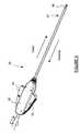
- FIG. 1is an illustration of a conventional surgical rongeur.
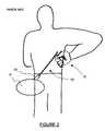
- FIG. 2is an illustration of an operator holding the surgical rongeur of FIG. 1 when the rongeur is introduced in a cannulated posterolateral approach into a patient.
- FIG. 3is a perspective view of the present invention.
- FIG. 4is a close-up perspective view corresponding to FIG. 3 .
- FIG. 5is a sectional view of the invention corresponding to FIGS. 3 and 4.
- FIG. 6shows an operator using the present invention in a cannulated posterolateral approach.
- FIG. 7Ashows an operator's left hand holding the invention with the thumb pointed in a proximal direction.
- FIG. 7Bshows an operator's right hand holding the invention with the thumb pointed in a proximal direction.
- FIG. 7Cshows an operator's left hand holding the invention with the thumb pointed in a distal direction.
- FIG. 7Dshows an operator's right hand holding the invention with the thumb pointed in a distal direction.
- FIG. 8is a perspective view of the invention, adapted for use on a suction punch.
- FIG. 9is a perspective view of the invention, adapted for use in controlling the positioning and jaw movement of an articulator.
- FIG. 10is an additional view of the invention, adapted for use in controlling the positioning and jaw movement of an articulator.
- FIG. 11is a cut-away view of the present invention.
- FIG. 1is an illustration of a typical surgical rongeur 10 having a side opening 12 with an internal cutting blade 14 .
- the internal cutting blade 14is moved axially by squeezing pistol grip 15 .
- FIG. 2shows an operator holding the rongeur of FIG. 1 in a cannulated posterolateral approach into a patient with rongeur 10 received into cannula 20 which is posterolaterally inserted into patient P.
- a disadvantage of conventional pistol grip 15is that the operator is forced to considerably extend their arm and rotate their wrist such that pistol grip 15 can be held with the operator's hand pointing downwardly in a distal direction.
- the present inventionprovides a novel control grip assembly 30 , comprising a body 32 and a pair of handles 34 which when squeezed together in unison control the actuation of an axially displaceable actuator mechanism.
- actuator mechanismmay, for example, control the movement of a cutting blade 35 in a rongeur tube 37 , as shown.
- each of handles 34may optionally have a series of traction grooves or protrusions 39 disposed along their outer perimeter.
- An optional valve 31may be used to control a suctioning air flow through rongeur tube 37 .
- Each of handles 34are pivotally connected at points 36 to the frame of body 32 .
- handle 34is connected with pivot point 36 being disposed at the proximal end of the handle.
- a strut 38connects handle 34 to actuator controller 40 .
- Actuator controller 40preferably is adapted to slide axially within body 32 .
- actuator controller 40can be displaced in an axial direction.
- the displacement of the axial controllercan be used either to control operation of a wide variety of surgical instruments.
- axial movement of actuator controller 40can control the articulation of an articulating arm, or the axial displacement of a cutting blade in a surgical rongeur or suction punch as shown.
- FIG. 6shows the advantages of using the present invention when operating in a cannulated posterolateral approach.
- the operatorcan grasp control grip assembly 30 in a “dagger” type grip, holding handles 34 in the palm of their hand, with their thumb pointed in a proximal direction relative to the device, (i.e., away from the “operating” distal end of the instrument), thus preventing excessive turning of their wrist to an uncomfortable position, as was shown with the conventional pistol grip seen in FIG. 2 .
- the actuator grip assembly 30can optionally be rotated in direction R by 180° such that it is possible to grasp the device from either side, using the same hand.
- FIGS. 7A to 7 Dillustrate further advantages of the present invention, showing the “left and right reversible”, “front and back reversible” and “top and bottom reversible” nature of the invention.
- the present control grip 30can be conveniently held in an operator's left hand between the index finger and the thumb and/or the volar-radial aspect of the palm, with the thumb pointed in a proximal direction.
- FIG. 7Bshows a similar grip with the operator's right hand holding the invention with their thumb pointed in a proximal direction.
- FIG. 7Cshows an operator's left hand holding the invention with the thumb pointed in a distal direction, (held between the little finger and the volar-ulnal aspect of the palm), and FIG. 7D conversely shows an operator's right hand holding the invention with the thumb pointed in a distal direction.
- FIG. 8shows actuator grip assembly 30 outfitted with a valve 50 , which may be controlled by the operator's thumb.
- valve 50opens and closes the suction punch.
- FIGS. 9 and 10show actuator grip assembly 30 outfitted with a slidable controller 60 which is movable back and forth in direction D.
- the squeezing together of handles 34operates to open and close jaws of an articulator, and the slidable positioning of controller 60 is used to control the degree of articulation of the articulator. Accordingly, an advantage of the present invention is that it permits one-hand control of both the opening and closing of articulator jaws and also the degree to which the articulator is angled.
Landscapes
- Health & Medical Sciences (AREA)
- Surgery (AREA)
- Life Sciences & Earth Sciences (AREA)
- Biomedical Technology (AREA)
- Nuclear Medicine, Radiotherapy & Molecular Imaging (AREA)
- Engineering & Computer Science (AREA)
- Ophthalmology & Optometry (AREA)
- Heart & Thoracic Surgery (AREA)
- Medical Informatics (AREA)
- Molecular Biology (AREA)
- Animal Behavior & Ethology (AREA)
- General Health & Medical Sciences (AREA)
- Public Health (AREA)
- Veterinary Medicine (AREA)
- Surgical Instruments (AREA)
Abstract
Description
Claims (3)
Priority Applications (1)
| Application Number | Priority Date | Filing Date | Title |
|---|---|---|---|
| US09/717,839US6533797B1 (en) | 1999-11-24 | 2000-11-21 | Control grip assembly |
Applications Claiming Priority (2)
| Application Number | Priority Date | Filing Date | Title |
|---|---|---|---|
| US16741599P | 1999-11-24 | 1999-11-24 | |
| US09/717,839US6533797B1 (en) | 1999-11-24 | 2000-11-21 | Control grip assembly |
Publications (1)
| Publication Number | Publication Date |
|---|---|
| US6533797B1true US6533797B1 (en) | 2003-03-18 |
Family
ID=26863148
Family Applications (1)
| Application Number | Title | Priority Date | Filing Date |
|---|---|---|---|
| US09/717,839Expired - Fee RelatedUS6533797B1 (en) | 1999-11-24 | 2000-11-21 | Control grip assembly |
Country Status (1)
| Country | Link |
|---|---|
| US (1) | US6533797B1 (en) |
Cited By (59)
| Publication number | Priority date | Publication date | Assignee | Title |
|---|---|---|---|---|
| US20040158233A1 (en)* | 2002-07-25 | 2004-08-12 | Dicesare Paul | Enhanced dexterity surgical hand piece |
| US20050070754A1 (en)* | 2003-09-29 | 2005-03-31 | Rudolph Nobis | Actuation mechanism for flexible endoscopic device |
| US20050070885A1 (en)* | 2003-09-29 | 2005-03-31 | Rudolph Nobis | Method of operating an endoscopic device with one hand |
| US20050070764A1 (en)* | 2003-09-29 | 2005-03-31 | Rudolph Nobis | Handle for endoscopic device |
| US20050119692A1 (en)* | 2002-05-10 | 2005-06-02 | Zoltan Szabo | Grip arrangement for a medical instrument, and such medical instrument |
| US20070055275A1 (en)* | 2005-08-16 | 2007-03-08 | Laurent Schaller | Methods for Limiting the Movement of Material Introduced Between Layers of Spinal Tissue |
| US20070191674A1 (en)* | 2002-09-06 | 2007-08-16 | C. R. Bard, Inc. | External endoscopic acessory control system |
| US20070239188A1 (en)* | 2006-04-10 | 2007-10-11 | Agamatrix, Inc. | Lancing Device |
| US20110093005A1 (en)* | 2009-10-09 | 2011-04-21 | Applied Medical Resources Corporation | Single Port Instruments |
| US20120078037A1 (en)* | 1998-08-12 | 2012-03-29 | Maquet Cardiovascular Llc | Vessel harvester |
| US8366773B2 (en) | 2005-08-16 | 2013-02-05 | Benvenue Medical, Inc. | Apparatus and method for treating bone |
| US8454617B2 (en) | 2005-08-16 | 2013-06-04 | Benvenue Medical, Inc. | Devices for treating the spine |
| US20130211197A1 (en)* | 2010-03-16 | 2013-08-15 | Olympus Medical Systems Corporation | Endoscopic Surgical Instrument |
| US8535327B2 (en) | 2009-03-17 | 2013-09-17 | Benvenue Medical, Inc. | Delivery apparatus for use with implantable medical devices |
| US8591583B2 (en) | 2005-08-16 | 2013-11-26 | Benvenue Medical, Inc. | Devices for treating the spine |
| US20140121692A1 (en)* | 2012-10-26 | 2014-05-01 | Jochen Stefan | Actuation grip for a microsurgical instrument, and microsurgical instrument |
| US8814873B2 (en) | 2011-06-24 | 2014-08-26 | Benvenue Medical, Inc. | Devices and methods for treating bone tissue |
| US20150305762A1 (en)* | 2014-04-24 | 2015-10-29 | Raymond Dunn | Contoured surgical forceps |
| US9451940B2 (en) | 2008-12-26 | 2016-09-27 | Pantheon Spinal, Llc | Method of retroperitoneal lateral insertion of spinal implants |
| US20160302810A1 (en)* | 2015-04-16 | 2016-10-20 | Whitney Surgical Labs, LLC | Surgical Tool |
| US9788963B2 (en) | 2003-02-14 | 2017-10-17 | DePuy Synthes Products, Inc. | In-situ formed intervertebral fusion device and method |
| US10085783B2 (en) | 2013-03-14 | 2018-10-02 | Izi Medical Products, Llc | Devices and methods for treating bone tissue |
| US10321833B2 (en) | 2016-10-05 | 2019-06-18 | Innovative Surgical Solutions. | Neural locating method |
| US10376209B2 (en) | 2013-09-20 | 2019-08-13 | Innovative Surgical Solutions, Llc | Neural locating method |
| US10376208B2 (en) | 2013-09-20 | 2019-08-13 | Innovative Surgical Solutions, Llc | Nerve mapping system |
| US10449002B2 (en) | 2013-09-20 | 2019-10-22 | Innovative Surgical Solutions, Llc | Method of mapping a nerve |
| US10478096B2 (en) | 2013-08-13 | 2019-11-19 | Innovative Surgical Solutions. | Neural event detection |
| US10478097B2 (en) | 2013-08-13 | 2019-11-19 | Innovative Surgical Solutions | Neural event detection |
| US10507012B2 (en) | 2000-11-17 | 2019-12-17 | Maquet Cardiovascular Llc | Vein harvesting system and method |
| US10716553B2 (en) | 2017-04-19 | 2020-07-21 | Pantheon Spinal, Llc | Spine surgery retractor system and related methods |
| US10869616B2 (en) | 2018-06-01 | 2020-12-22 | DePuy Synthes Products, Inc. | Neural event detection |
| US10870002B2 (en) | 2018-10-12 | 2020-12-22 | DePuy Synthes Products, Inc. | Neuromuscular sensing device with multi-sensor array |
| US10888433B2 (en) | 2016-12-14 | 2021-01-12 | DePuy Synthes Products, Inc. | Intervertebral implant inserter and related methods |
| US10940016B2 (en) | 2017-07-05 | 2021-03-09 | Medos International Sarl | Expandable intervertebral fusion cage |
| US10966840B2 (en) | 2010-06-24 | 2021-04-06 | DePuy Synthes Products, Inc. | Enhanced cage insertion assembly |
| US10973652B2 (en) | 2007-06-26 | 2021-04-13 | DePuy Synthes Products, Inc. | Highly lordosed fusion cage |
| US20210338042A1 (en)* | 2019-01-21 | 2021-11-04 | Olympus Corporation | Image processing apparatus, diagnosis supporting method, and recording medium recording image processing program |
| US11273050B2 (en) | 2006-12-07 | 2022-03-15 | DePuy Synthes Products, Inc. | Intervertebral implant |
| US11344424B2 (en) | 2017-06-14 | 2022-05-31 | Medos International Sarl | Expandable intervertebral implant and related methods |
| US11399777B2 (en) | 2019-09-27 | 2022-08-02 | DePuy Synthes Products, Inc. | Intraoperative neural monitoring system and method |
| US11426290B2 (en) | 2015-03-06 | 2022-08-30 | DePuy Synthes Products, Inc. | Expandable intervertebral implant, system, kit and method |
| US11426286B2 (en) | 2020-03-06 | 2022-08-30 | Eit Emerging Implant Technologies Gmbh | Expandable intervertebral implant |
| US11446155B2 (en) | 2017-05-08 | 2022-09-20 | Medos International Sarl | Expandable cage |
| US11446156B2 (en) | 2018-10-25 | 2022-09-20 | Medos International Sarl | Expandable intervertebral implant, inserter instrument, and related methods |
| US11452607B2 (en) | 2010-10-11 | 2022-09-27 | DePuy Synthes Products, Inc. | Expandable interspinous process spacer implant |
| US11497619B2 (en) | 2013-03-07 | 2022-11-15 | DePuy Synthes Products, Inc. | Intervertebral implant |
| US11510788B2 (en) | 2016-06-28 | 2022-11-29 | Eit Emerging Implant Technologies Gmbh | Expandable, angularly adjustable intervertebral cages |
| US11596522B2 (en) | 2016-06-28 | 2023-03-07 | Eit Emerging Implant Technologies Gmbh | Expandable and angularly adjustable intervertebral cages with articulating joint |
| US11602438B2 (en) | 2008-04-05 | 2023-03-14 | DePuy Synthes Products, Inc. | Expandable intervertebral implant |
| US11607321B2 (en) | 2009-12-10 | 2023-03-21 | DePuy Synthes Products, Inc. | Bellows-like expandable interbody fusion cage |
| US11612491B2 (en) | 2009-03-30 | 2023-03-28 | DePuy Synthes Products, Inc. | Zero profile spinal fusion cage |
| US11654033B2 (en) | 2010-06-29 | 2023-05-23 | DePuy Synthes Products, Inc. | Distractible intervertebral implant |
| US11737881B2 (en) | 2008-01-17 | 2023-08-29 | DePuy Synthes Products, Inc. | Expandable intervertebral implant and associated method of manufacturing the same |
| US11752009B2 (en) | 2021-04-06 | 2023-09-12 | Medos International Sarl | Expandable intervertebral fusion cage |
| US11850160B2 (en) | 2021-03-26 | 2023-12-26 | Medos International Sarl | Expandable lordotic intervertebral fusion cage |
| US11911287B2 (en) | 2010-06-24 | 2024-02-27 | DePuy Synthes Products, Inc. | Lateral spondylolisthesis reduction cage |
| USRE49973E1 (en) | 2013-02-28 | 2024-05-21 | DePuy Synthes Products, Inc. | Expandable intervertebral implant, system, kit and method |
| US12090064B2 (en) | 2022-03-01 | 2024-09-17 | Medos International Sarl | Stabilization members for expandable intervertebral implants, and related systems and methods |
| US12440346B2 (en) | 2023-03-31 | 2025-10-14 | DePuy Synthes Products, Inc. | Expandable intervertebral implant |
Citations (3)
| Publication number | Priority date | Publication date | Assignee | Title |
|---|---|---|---|---|
| US5370658A (en)* | 1992-11-05 | 1994-12-06 | Synergetics, Inc. | Microsurgical instrument having dexterous handle with interchangeable instrument heads |
| US5383895A (en)* | 1993-02-10 | 1995-01-24 | Unisurge, Inc. | Endoscopic surgical grasper and method |
| US5501698A (en)* | 1994-02-14 | 1996-03-26 | Heartport, Inc. | Endoscopic microsurgical instruments and methods |
- 2000
- 2000-11-21USUS09/717,839patent/US6533797B1/ennot_activeExpired - Fee Related
Patent Citations (4)
| Publication number | Priority date | Publication date | Assignee | Title |
|---|---|---|---|---|
| US5370658A (en)* | 1992-11-05 | 1994-12-06 | Synergetics, Inc. | Microsurgical instrument having dexterous handle with interchangeable instrument heads |
| US5383895A (en)* | 1993-02-10 | 1995-01-24 | Unisurge, Inc. | Endoscopic surgical grasper and method |
| US5501698A (en)* | 1994-02-14 | 1996-03-26 | Heartport, Inc. | Endoscopic microsurgical instruments and methods |
| US5618306A (en)* | 1994-02-14 | 1997-04-08 | Heartport, Inc. | Endoscopic microsurgical instruments and methods |
Cited By (158)
| Publication number | Priority date | Publication date | Assignee | Title |
|---|---|---|---|---|
| US20120078037A1 (en)* | 1998-08-12 | 2012-03-29 | Maquet Cardiovascular Llc | Vessel harvester |
| US10507012B2 (en) | 2000-11-17 | 2019-12-17 | Maquet Cardiovascular Llc | Vein harvesting system and method |
| US8167904B2 (en)* | 2002-05-10 | 2012-05-01 | Karl Storz Gmbh & Co. Kg | Grip arrangement for a medical instrument, and such medical instrument |
| US20050119692A1 (en)* | 2002-05-10 | 2005-06-02 | Zoltan Szabo | Grip arrangement for a medical instrument, and such medical instrument |
| US7758608B2 (en)* | 2002-07-25 | 2010-07-20 | Dicesare Paul | Enhanced dexterity surgical hand piece |
| US20040158233A1 (en)* | 2002-07-25 | 2004-08-12 | Dicesare Paul | Enhanced dexterity surgical hand piece |
| US7717846B2 (en)* | 2002-09-06 | 2010-05-18 | C.R. Bard, Inc. | External endoscopic accessory control system |
| US20070191674A1 (en)* | 2002-09-06 | 2007-08-16 | C. R. Bard, Inc. | External endoscopic acessory control system |
| US9808351B2 (en) | 2003-02-14 | 2017-11-07 | DePuy Synthes Products, Inc. | In-situ formed intervertebral fusion device and method |
| US10376372B2 (en) | 2003-02-14 | 2019-08-13 | DePuy Synthes Products, Inc. | In-situ formed intervertebral fusion device and method |
| US10085843B2 (en) | 2003-02-14 | 2018-10-02 | DePuy Synthes Products, Inc. | In-situ formed intervertebral fusion device and method |
| US9925060B2 (en) | 2003-02-14 | 2018-03-27 | DePuy Synthes Products, Inc. | In-situ formed intervertebral fusion device and method |
| US9814590B2 (en) | 2003-02-14 | 2017-11-14 | DePuy Synthes Products, Inc. | In-situ formed intervertebral fusion device and method |
| US9814589B2 (en) | 2003-02-14 | 2017-11-14 | DePuy Synthes Products, Inc. | In-situ formed intervertebral fusion device and method |
| US10492918B2 (en) | 2003-02-14 | 2019-12-03 | DePuy Synthes Products, Inc. | In-situ formed intervertebral fusion device and method |
| US9801729B2 (en) | 2003-02-14 | 2017-10-31 | DePuy Synthes Products, Inc. | In-situ formed intervertebral fusion device and method |
| US9788963B2 (en) | 2003-02-14 | 2017-10-17 | DePuy Synthes Products, Inc. | In-situ formed intervertebral fusion device and method |
| US10555817B2 (en) | 2003-02-14 | 2020-02-11 | DePuy Synthes Products, Inc. | In-situ formed intervertebral fusion device and method |
| US10433971B2 (en) | 2003-02-14 | 2019-10-08 | DePuy Synthes Products, Inc. | In-situ formed intervertebral fusion device and method |
| US10575959B2 (en) | 2003-02-14 | 2020-03-03 | DePuy Synthes Products, Inc. | In-situ formed intervertebral fusion device and method |
| US10420651B2 (en) | 2003-02-14 | 2019-09-24 | DePuy Synthes Products, Inc. | In-situ formed intervertebral fusion device and method |
| US10583013B2 (en) | 2003-02-14 | 2020-03-10 | DePuy Synthes Products, Inc. | In-situ formed intervertebral fusion device and method |
| US10639164B2 (en) | 2003-02-14 | 2020-05-05 | DePuy Synthes Products, Inc. | In-situ formed intervertebral fusion device and method |
| US10786361B2 (en) | 2003-02-14 | 2020-09-29 | DePuy Synthes Products, Inc. | In-situ formed intervertebral fusion device and method |
| US11096794B2 (en) | 2003-02-14 | 2021-08-24 | DePuy Synthes Products, Inc. | In-situ formed intervertebral fusion device and method |
| US11207187B2 (en) | 2003-02-14 | 2021-12-28 | DePuy Synthes Products, Inc. | In-situ formed intervertebral fusion device and method |
| US11432938B2 (en) | 2003-02-14 | 2022-09-06 | DePuy Synthes Products, Inc. | In-situ intervertebral fusion device and method |
| US10405986B2 (en) | 2003-02-14 | 2019-09-10 | DePuy Synthes Products, Inc. | In-situ formed intervertebral fusion device and method |
| US7708756B2 (en)* | 2003-09-29 | 2010-05-04 | Ethicon Endo-Surgery, Inc. | Actuation mechanism for flexible endoscopic device |
| US7789825B2 (en)* | 2003-09-29 | 2010-09-07 | Ethicon Endo-Surgery, Inc. | Handle for endoscopic device |
| US20050070754A1 (en)* | 2003-09-29 | 2005-03-31 | Rudolph Nobis | Actuation mechanism for flexible endoscopic device |
| US20050070885A1 (en)* | 2003-09-29 | 2005-03-31 | Rudolph Nobis | Method of operating an endoscopic device with one hand |
| AU2011201399B2 (en)* | 2003-09-29 | 2012-12-13 | Ethicon Endo-Surgery, Inc. | Handle for endoscopic device |
| US20050070764A1 (en)* | 2003-09-29 | 2005-03-31 | Rudolph Nobis | Handle for endoscopic device |
| US7094202B2 (en)* | 2003-09-29 | 2006-08-22 | Ethicon Endo-Surgery, Inc. | Method of operating an endoscopic device with one hand |
| US20100174311A1 (en)* | 2003-09-29 | 2010-07-08 | Rudolph Nobis | Actuation Apparatus and Method |
| US9259326B2 (en) | 2005-08-16 | 2016-02-16 | Benvenue Medical, Inc. | Spinal tissue distraction devices |
| US8057544B2 (en) | 2005-08-16 | 2011-11-15 | Benvenue Medical, Inc. | Methods of distracting tissue layers of the human spine |
| US8591583B2 (en) | 2005-08-16 | 2013-11-26 | Benvenue Medical, Inc. | Devices for treating the spine |
| US7967864B2 (en) | 2005-08-16 | 2011-06-28 | Benvenue Medical, Inc. | Spinal tissue distraction devices |
| US8801787B2 (en) | 2005-08-16 | 2014-08-12 | Benvenue Medical, Inc. | Methods of distracting tissue layers of the human spine |
| US8808376B2 (en) | 2005-08-16 | 2014-08-19 | Benvenue Medical, Inc. | Intravertebral implants |
| US8366773B2 (en) | 2005-08-16 | 2013-02-05 | Benvenue Medical, Inc. | Apparatus and method for treating bone |
| US8882836B2 (en) | 2005-08-16 | 2014-11-11 | Benvenue Medical, Inc. | Apparatus and method for treating bone |
| US8961609B2 (en) | 2005-08-16 | 2015-02-24 | Benvenue Medical, Inc. | Devices for distracting tissue layers of the human spine |
| US7967865B2 (en) | 2005-08-16 | 2011-06-28 | Benvenue Medical, Inc. | Devices for limiting the movement of material introduced between layers of spinal tissue |
| US8979929B2 (en) | 2005-08-16 | 2015-03-17 | Benvenue Medical, Inc. | Spinal tissue distraction devices |
| US9044338B2 (en) | 2005-08-16 | 2015-06-02 | Benvenue Medical, Inc. | Spinal tissue distraction devices |
| US9066808B2 (en) | 2005-08-16 | 2015-06-30 | Benvenue Medical, Inc. | Method of interdigitating flowable material with bone tissue |
| US8454617B2 (en) | 2005-08-16 | 2013-06-04 | Benvenue Medical, Inc. | Devices for treating the spine |
| US7963993B2 (en) | 2005-08-16 | 2011-06-21 | Benvenue Medical, Inc. | Methods of distracting tissue layers of the human spine |
| US20070055273A1 (en)* | 2005-08-16 | 2007-03-08 | Laurent Schaller | Methods of Distracting Tissue Layers of the Human Spine |
| US7955391B2 (en) | 2005-08-16 | 2011-06-07 | Benvenue Medical, Inc. | Methods for limiting the movement of material introduced between layers of spinal tissue |
| US9326866B2 (en) | 2005-08-16 | 2016-05-03 | Benvenue Medical, Inc. | Devices for treating the spine |
| US20070055275A1 (en)* | 2005-08-16 | 2007-03-08 | Laurent Schaller | Methods for Limiting the Movement of Material Introduced Between Layers of Spinal Tissue |
| US20070055265A1 (en)* | 2005-08-16 | 2007-03-08 | Laurent Schaller | Devices For Limiting the Movement Of Material Introduced Between Layers Of Spinal Tissue |
| US7785368B2 (en) | 2005-08-16 | 2010-08-31 | Benvenue Medical, Inc. | Spinal tissue distraction devices |
| US20070055271A1 (en)* | 2005-08-16 | 2007-03-08 | Laurent Schaller | Spinal Tissue Distraction Devices |
| US7670375B2 (en) | 2005-08-16 | 2010-03-02 | Benvenue Medical, Inc. | Methods for limiting the movement of material introduced between layers of spinal tissue |
| US9788974B2 (en) | 2005-08-16 | 2017-10-17 | Benvenue Medical, Inc. | Spinal tissue distraction devices |
| US7670374B2 (en) | 2005-08-16 | 2010-03-02 | Benvenue Medical, Inc. | Methods of distracting tissue layers of the human spine |
| US7666227B2 (en) | 2005-08-16 | 2010-02-23 | Benvenue Medical, Inc. | Devices for limiting the movement of material introduced between layers of spinal tissue |
| US7666226B2 (en) | 2005-08-16 | 2010-02-23 | Benvenue Medical, Inc. | Spinal tissue distraction devices |
| US20090182386A1 (en)* | 2005-08-16 | 2009-07-16 | Laurent Schaller | Spinal tissue distraction devices |
| US8556978B2 (en) | 2005-08-16 | 2013-10-15 | Benvenue Medical, Inc. | Devices and methods for treating the vertebral body |
| US10028840B2 (en) | 2005-08-16 | 2018-07-24 | Izi Medical Products, Llc | Spinal tissue distraction devices |
| US20070239188A1 (en)* | 2006-04-10 | 2007-10-11 | Agamatrix, Inc. | Lancing Device |
| US8162968B2 (en)* | 2006-04-10 | 2012-04-24 | Agamatrix, Inc. | Lancing device |
| US11660206B2 (en) | 2006-12-07 | 2023-05-30 | DePuy Synthes Products, Inc. | Intervertebral implant |
| US11642229B2 (en) | 2006-12-07 | 2023-05-09 | DePuy Synthes Products, Inc. | Intervertebral implant |
| US11712345B2 (en) | 2006-12-07 | 2023-08-01 | DePuy Synthes Products, Inc. | Intervertebral implant |
| US11273050B2 (en) | 2006-12-07 | 2022-03-15 | DePuy Synthes Products, Inc. | Intervertebral implant |
| US11432942B2 (en) | 2006-12-07 | 2022-09-06 | DePuy Synthes Products, Inc. | Intervertebral implant |
| US11497618B2 (en) | 2006-12-07 | 2022-11-15 | DePuy Synthes Products, Inc. | Intervertebral implant |
| US10426629B2 (en) | 2007-02-21 | 2019-10-01 | Benvenue Medical, Inc. | Devices for treating the spine |
| US8968408B2 (en) | 2007-02-21 | 2015-03-03 | Benvenue Medical, Inc. | Devices for treating the spine |
| US10285821B2 (en) | 2007-02-21 | 2019-05-14 | Benvenue Medical, Inc. | Devices for treating the spine |
| US9642712B2 (en) | 2007-02-21 | 2017-05-09 | Benvenue Medical, Inc. | Methods for treating the spine |
| US10575963B2 (en) | 2007-02-21 | 2020-03-03 | Benvenue Medical, Inc. | Devices for treating the spine |
| US11622868B2 (en) | 2007-06-26 | 2023-04-11 | DePuy Synthes Products, Inc. | Highly lordosed fusion cage |
| US10973652B2 (en) | 2007-06-26 | 2021-04-13 | DePuy Synthes Products, Inc. | Highly lordosed fusion cage |
| US11737881B2 (en) | 2008-01-17 | 2023-08-29 | DePuy Synthes Products, Inc. | Expandable intervertebral implant and associated method of manufacturing the same |
| US11707359B2 (en) | 2008-04-05 | 2023-07-25 | DePuy Synthes Products, Inc. | Expandable intervertebral implant |
| US12011361B2 (en) | 2008-04-05 | 2024-06-18 | DePuy Synthes Products, Inc. | Expandable intervertebral implant |
| US11712341B2 (en) | 2008-04-05 | 2023-08-01 | DePuy Synthes Products, Inc. | Expandable intervertebral implant |
| US11617655B2 (en) | 2008-04-05 | 2023-04-04 | DePuy Synthes Products, Inc. | Expandable intervertebral implant |
| US11701234B2 (en) | 2008-04-05 | 2023-07-18 | DePuy Synthes Products, Inc. | Expandable intervertebral implant |
| US12023255B2 (en) | 2008-04-05 | 2024-07-02 | DePuy Synthes Products, Inc. | Expandable inter vertebral implant |
| US11602438B2 (en) | 2008-04-05 | 2023-03-14 | DePuy Synthes Products, Inc. | Expandable intervertebral implant |
| US11712342B2 (en) | 2008-04-05 | 2023-08-01 | DePuy Synthes Products, Inc. | Expandable intervertebral implant |
| US11969359B2 (en) | 2008-12-26 | 2024-04-30 | Pantheon Spinal, Llc | Method of retroperitoneal lateral insertion of spinal implants |
| US9451940B2 (en) | 2008-12-26 | 2016-09-27 | Pantheon Spinal, Llc | Method of retroperitoneal lateral insertion of spinal implants |
| US12383411B2 (en) | 2008-12-26 | 2025-08-12 | Pantheon Spinal, Llc | Spinal surgery methods and devices |
| US10959860B2 (en) | 2008-12-26 | 2021-03-30 | Pantheon Spinal, Llc | Method of retroperitoneal lateral insertion of spinal implants |
| US10085854B2 (en) | 2008-12-26 | 2018-10-02 | Pantheon Spinal, Llc | Method of retroperitoneal lateral insertion of spinal implants |
| US8535327B2 (en) | 2009-03-17 | 2013-09-17 | Benvenue Medical, Inc. | Delivery apparatus for use with implantable medical devices |
| US11612491B2 (en) | 2009-03-30 | 2023-03-28 | DePuy Synthes Products, Inc. | Zero profile spinal fusion cage |
| US12097124B2 (en) | 2009-03-30 | 2024-09-24 | DePuy Synthes Products, Inc. | Zero profile spinal fusion cage |
| US20110093005A1 (en)* | 2009-10-09 | 2011-04-21 | Applied Medical Resources Corporation | Single Port Instruments |
| US9113939B2 (en) | 2009-10-09 | 2015-08-25 | Applied Medical Resources Corporation | Single port instruments |
| US10420576B2 (en) | 2009-10-09 | 2019-09-24 | Applied Medical Resources Corporation | Single port instruments |
| US11622783B2 (en) | 2009-10-09 | 2023-04-11 | Applied Medical Resources Corporation | Single port instruments |
| US11607321B2 (en) | 2009-12-10 | 2023-03-21 | DePuy Synthes Products, Inc. | Bellows-like expandable interbody fusion cage |
| US20130211197A1 (en)* | 2010-03-16 | 2013-08-15 | Olympus Medical Systems Corporation | Endoscopic Surgical Instrument |
| US11872139B2 (en) | 2010-06-24 | 2024-01-16 | DePuy Synthes Products, Inc. | Enhanced cage insertion assembly |
| US10966840B2 (en) | 2010-06-24 | 2021-04-06 | DePuy Synthes Products, Inc. | Enhanced cage insertion assembly |
| US12318304B2 (en) | 2010-06-24 | 2025-06-03 | DePuy Synthes Products, Inc. | Lateral spondylolisthesis reduction cage |
| US11911287B2 (en) | 2010-06-24 | 2024-02-27 | DePuy Synthes Products, Inc. | Lateral spondylolisthesis reduction cage |
| US11654033B2 (en) | 2010-06-29 | 2023-05-23 | DePuy Synthes Products, Inc. | Distractible intervertebral implant |
| US11452607B2 (en) | 2010-10-11 | 2022-09-27 | DePuy Synthes Products, Inc. | Expandable interspinous process spacer implant |
| US8814873B2 (en) | 2011-06-24 | 2014-08-26 | Benvenue Medical, Inc. | Devices and methods for treating bone tissue |
| US9314252B2 (en) | 2011-06-24 | 2016-04-19 | Benvenue Medical, Inc. | Devices and methods for treating bone tissue |
| US20140121692A1 (en)* | 2012-10-26 | 2014-05-01 | Jochen Stefan | Actuation grip for a microsurgical instrument, and microsurgical instrument |
| US9566081B2 (en)* | 2012-10-26 | 2017-02-14 | Karl Storz Gmbh & Co. Kg | Actuation grip for a microsurgical instrument, and microsurgical instrument |
| USRE49973E1 (en) | 2013-02-28 | 2024-05-21 | DePuy Synthes Products, Inc. | Expandable intervertebral implant, system, kit and method |
| US11497619B2 (en) | 2013-03-07 | 2022-11-15 | DePuy Synthes Products, Inc. | Intervertebral implant |
| US11850164B2 (en) | 2013-03-07 | 2023-12-26 | DePuy Synthes Products, Inc. | Intervertebral implant |
| US10085783B2 (en) | 2013-03-14 | 2018-10-02 | Izi Medical Products, Llc | Devices and methods for treating bone tissue |
| US10478096B2 (en) | 2013-08-13 | 2019-11-19 | Innovative Surgical Solutions. | Neural event detection |
| US10478097B2 (en) | 2013-08-13 | 2019-11-19 | Innovative Surgical Solutions | Neural event detection |
| US10449002B2 (en) | 2013-09-20 | 2019-10-22 | Innovative Surgical Solutions, Llc | Method of mapping a nerve |
| US10376208B2 (en) | 2013-09-20 | 2019-08-13 | Innovative Surgical Solutions, Llc | Nerve mapping system |
| US10376209B2 (en) | 2013-09-20 | 2019-08-13 | Innovative Surgical Solutions, Llc | Neural locating method |
| US10201362B2 (en)* | 2014-04-24 | 2019-02-12 | University Of Massachusetts | Contoured surgical forceps |
| US20150305762A1 (en)* | 2014-04-24 | 2015-10-29 | Raymond Dunn | Contoured surgical forceps |
| US11426290B2 (en) | 2015-03-06 | 2022-08-30 | DePuy Synthes Products, Inc. | Expandable intervertebral implant, system, kit and method |
| US20160302810A1 (en)* | 2015-04-16 | 2016-10-20 | Whitney Surgical Labs, LLC | Surgical Tool |
| US11596523B2 (en) | 2016-06-28 | 2023-03-07 | Eit Emerging Implant Technologies Gmbh | Expandable and angularly adjustable articulating intervertebral cages |
| US11596522B2 (en) | 2016-06-28 | 2023-03-07 | Eit Emerging Implant Technologies Gmbh | Expandable and angularly adjustable intervertebral cages with articulating joint |
| US11510788B2 (en) | 2016-06-28 | 2022-11-29 | Eit Emerging Implant Technologies Gmbh | Expandable, angularly adjustable intervertebral cages |
| US12433757B2 (en) | 2016-06-28 | 2025-10-07 | Eit Emerging Implant Technologies Gmbh | Expandable, angularly adjustable and articulating intervertebral cages |
| US12390343B2 (en) | 2016-06-28 | 2025-08-19 | Eit Emerging Implant Technologies Gmbh | Expandable, angularly adjustable intervertebral cages |
| US10321833B2 (en) | 2016-10-05 | 2019-06-18 | Innovative Surgical Solutions. | Neural locating method |
| US11311222B2 (en) | 2016-10-05 | 2022-04-26 | Innovative Surgical Solutions | Neural locating system |
| US12109042B2 (en) | 2016-10-05 | 2024-10-08 | Innovative Surgical Solutions, Llc | Neural locating system and method |
| US10888433B2 (en) | 2016-12-14 | 2021-01-12 | DePuy Synthes Products, Inc. | Intervertebral implant inserter and related methods |
| US10716553B2 (en) | 2017-04-19 | 2020-07-21 | Pantheon Spinal, Llc | Spine surgery retractor system and related methods |
| US11478237B2 (en) | 2017-04-19 | 2022-10-25 | Pantheon Spinal, Llc | Spine surgery retractor system and related methods |
| US11963674B2 (en) | 2017-04-19 | 2024-04-23 | Pantheon Spinal, Llc | Spine surgery retractor system and related methods |
| US12427031B2 (en) | 2017-05-08 | 2025-09-30 | Medos International Sarl | Expandable cage |
| US11446155B2 (en) | 2017-05-08 | 2022-09-20 | Medos International Sarl | Expandable cage |
| US11344424B2 (en) | 2017-06-14 | 2022-05-31 | Medos International Sarl | Expandable intervertebral implant and related methods |
| US10940016B2 (en) | 2017-07-05 | 2021-03-09 | Medos International Sarl | Expandable intervertebral fusion cage |
| US10869616B2 (en) | 2018-06-01 | 2020-12-22 | DePuy Synthes Products, Inc. | Neural event detection |
| US12090320B2 (en) | 2018-10-12 | 2024-09-17 | DePuy Synthes Products, Inc. | Neuromuscular sensing device with multi-sensor array |
| US10870002B2 (en) | 2018-10-12 | 2020-12-22 | DePuy Synthes Products, Inc. | Neuromuscular sensing device with multi-sensor array |
| US11446156B2 (en) | 2018-10-25 | 2022-09-20 | Medos International Sarl | Expandable intervertebral implant, inserter instrument, and related methods |
| US20210338042A1 (en)* | 2019-01-21 | 2021-11-04 | Olympus Corporation | Image processing apparatus, diagnosis supporting method, and recording medium recording image processing program |
| US12414674B2 (en)* | 2019-01-21 | 2025-09-16 | Olympus Corporation | Image processing apparatus, diagnosis supporting method, and recording medium recording image processing program |
| US11399777B2 (en) | 2019-09-27 | 2022-08-02 | DePuy Synthes Products, Inc. | Intraoperative neural monitoring system and method |
| US12303301B2 (en) | 2019-09-27 | 2025-05-20 | DePuy Synthes Products, Inc. | Intraoperative neural monitoring system and method |
| US11426286B2 (en) | 2020-03-06 | 2022-08-30 | Eit Emerging Implant Technologies Gmbh | Expandable intervertebral implant |
| US11806245B2 (en) | 2020-03-06 | 2023-11-07 | Eit Emerging Implant Technologies Gmbh | Expandable intervertebral implant |
| US11850160B2 (en) | 2021-03-26 | 2023-12-26 | Medos International Sarl | Expandable lordotic intervertebral fusion cage |
| US12023258B2 (en) | 2021-04-06 | 2024-07-02 | Medos International Sarl | Expandable intervertebral fusion cage |
| US11752009B2 (en) | 2021-04-06 | 2023-09-12 | Medos International Sarl | Expandable intervertebral fusion cage |
| US12090064B2 (en) | 2022-03-01 | 2024-09-17 | Medos International Sarl | Stabilization members for expandable intervertebral implants, and related systems and methods |
| US12440346B2 (en) | 2023-03-31 | 2025-10-14 | DePuy Synthes Products, Inc. | Expandable intervertebral implant |
Similar Documents
| Publication | Publication Date | Title |
|---|---|---|
| US6533797B1 (en) | Control grip assembly | |
| US5893873A (en) | Surgical instrument having a handle with a removable, rotatable tip | |
| US5630831A (en) | Fingerlike medical instruments for use in laparoscopic procedures | |
| US7776065B2 (en) | End effector mechanism for a surgical instrument | |
| US20100191225A1 (en) | Surgical instrument handle | |
| US5354311A (en) | Deflecting forceps | |
| US5308357A (en) | Handle mechanism for manual instruments | |
| US6500188B2 (en) | Ultrasonic surgical instrument with finger actuator | |
| US20150342585A1 (en) | Surgical instrument | |
| US5476479A (en) | Handle for endoscopic surgical instruments and jaw structure | |
| US20140188159A1 (en) | Surgical tool | |
| CN102470017B (en) | Manipulator with manual grip and comfort articulation | |
| US11627978B2 (en) | Surgical instrument with mechanically operable lever | |
| JPH07204206A (en) | Reusable surgical equipment with rotatable internal shaft | |
| EP0543107B1 (en) | Endoscopic surgical instruments and jaw structure | |
| WO2006075153A1 (en) | Laparoscopic forceps | |
| US6299624B1 (en) | Handle for a medical instrument | |
| US10357268B2 (en) | Rotable and pivotable medical instrument | |
| EP3949879B1 (en) | Laparoscopic surgical instrument | |
| US6428530B1 (en) | Grip of endoscopic instrument | |
| EP0584723A1 (en) | Handle for endoscopic surgical instruments and jaw structure | |
| US5849021A (en) | Elongated thumb loop for surgical instrument | |
| US11877763B2 (en) | Surgical tool with reduced actuation force | |
| US20220273325A1 (en) | Surgical tool with reduced actuation force | |
| JPH0586223B2 (en) |
Legal Events
| Date | Code | Title | Description |
|---|---|---|---|
| AS | Assignment | Owner name:NUVASIVE, INC., CALIFORNIA Free format text:ASSIGNMENT OF ASSIGNORS INTEREST;ASSIGNORS:STONE, CORBETT W.;KING, NICOLEI R.;LYNCH, ROBERT S.;AND OTHERS;REEL/FRAME:011797/0423;SIGNING DATES FROM 20001228 TO 20010108 | |
| FPAY | Fee payment | Year of fee payment:4 | |
| AS | Assignment | Owner name:NUVASIVE, INC., CALIFORNIA Free format text:CHANGE OF ADDRESS;ASSIGNOR:NUVASIVE, INC.;REEL/FRAME:022706/0920 Effective date:20080811 | |
| REMI | Maintenance fee reminder mailed | ||
| LAPS | Lapse for failure to pay maintenance fees | ||
| STCH | Information on status: patent discontinuation | Free format text:PATENT EXPIRED DUE TO NONPAYMENT OF MAINTENANCE FEES UNDER 37 CFR 1.362 | |
| FP | Lapsed due to failure to pay maintenance fee | Effective date:20110318 | |
| AS | Assignment | Owner name:BANK OF AMERICA, N.A., AS ADMINISTRATIVE AGENT, NORTH CAROLINA Free format text:SECURITY INTEREST;ASSIGNORS:NUVASIVE, INC.;NUVASIVE CLINICAL SERVICES MONITORING, INC.;NUVASIVE CLINICAL SERVICES, INC.;AND OTHERS;REEL/FRAME:052918/0595 Effective date:20200224 |