US6533786B1 - Anterior cervical plating system - Google Patents
Anterior cervical plating systemDownload PDFInfo
- Publication number
- US6533786B1 US6533786B1US09/417,402US41740299AUS6533786B1US 6533786 B1US6533786 B1US 6533786B1US 41740299 AUS41740299 AUS 41740299AUS 6533786 B1US6533786 B1US 6533786B1
- Authority
- US
- United States
- Prior art keywords
- plate
- opening
- bone
- fastener
- fixation system
- Prior art date
- Legal status (The legal status is an assumption and is not a legal conclusion. Google has not performed a legal analysis and makes no representation as to the accuracy of the status listed.)
- Expired - Lifetime
Links
Images


Classifications
- A—HUMAN NECESSITIES
- A61—MEDICAL OR VETERINARY SCIENCE; HYGIENE
- A61B—DIAGNOSIS; SURGERY; IDENTIFICATION
- A61B17/00—Surgical instruments, devices or methods
- A61B17/56—Surgical instruments or methods for treatment of bones or joints; Devices specially adapted therefor
- A61B17/58—Surgical instruments or methods for treatment of bones or joints; Devices specially adapted therefor for osteosynthesis, e.g. bone plates, screws or setting implements
- A61B17/68—Internal fixation devices, including fasteners and spinal fixators, even if a part thereof projects from the skin
- A61B17/80—Cortical plates, i.e. bone plates; Instruments for holding or positioning cortical plates, or for compressing bones attached to cortical plates
- A61B17/8033—Cortical plates, i.e. bone plates; Instruments for holding or positioning cortical plates, or for compressing bones attached to cortical plates having indirect contact with screw heads, or having contact with screw heads maintained with the aid of additional components, e.g. nuts, wedges or head covers
- A61B17/8042—Cortical plates, i.e. bone plates; Instruments for holding or positioning cortical plates, or for compressing bones attached to cortical plates having indirect contact with screw heads, or having contact with screw heads maintained with the aid of additional components, e.g. nuts, wedges or head covers the additional component being a cover over the screw head
- A—HUMAN NECESSITIES
- A61—MEDICAL OR VETERINARY SCIENCE; HYGIENE
- A61B—DIAGNOSIS; SURGERY; IDENTIFICATION
- A61B17/00—Surgical instruments, devices or methods
- A61B17/16—Instruments for performing osteoclasis; Drills or chisels for bones; Trepans
- A61B17/17—Guides or aligning means for drills, mills, pins or wires
- A61B17/1728—Guides or aligning means for drills, mills, pins or wires for holes for bone plates or plate screws
- A—HUMAN NECESSITIES
- A61—MEDICAL OR VETERINARY SCIENCE; HYGIENE
- A61B—DIAGNOSIS; SURGERY; IDENTIFICATION
- A61B17/00—Surgical instruments, devices or methods
- A61B17/56—Surgical instruments or methods for treatment of bones or joints; Devices specially adapted therefor
- A61B17/58—Surgical instruments or methods for treatment of bones or joints; Devices specially adapted therefor for osteosynthesis, e.g. bone plates, screws or setting implements
- A61B17/68—Internal fixation devices, including fasteners and spinal fixators, even if a part thereof projects from the skin
- A61B17/70—Spinal positioners or stabilisers, e.g. stabilisers comprising fluid filler in an implant
- A61B17/7059—Cortical plates
- A—HUMAN NECESSITIES
- A61—MEDICAL OR VETERINARY SCIENCE; HYGIENE
- A61B—DIAGNOSIS; SURGERY; IDENTIFICATION
- A61B17/00—Surgical instruments, devices or methods
- A61B17/56—Surgical instruments or methods for treatment of bones or joints; Devices specially adapted therefor
- A61B17/58—Surgical instruments or methods for treatment of bones or joints; Devices specially adapted therefor for osteosynthesis, e.g. bone plates, screws or setting implements
- A61B17/68—Internal fixation devices, including fasteners and spinal fixators, even if a part thereof projects from the skin
- A61B17/80—Cortical plates, i.e. bone plates; Instruments for holding or positioning cortical plates, or for compressing bones attached to cortical plates
- A61B17/8004—Cortical plates, i.e. bone plates; Instruments for holding or positioning cortical plates, or for compressing bones attached to cortical plates with means for distracting or compressing the bone or bones
- A61B17/8014—Cortical plates, i.e. bone plates; Instruments for holding or positioning cortical plates, or for compressing bones attached to cortical plates with means for distracting or compressing the bone or bones the extension or compression force being caused by interaction of the plate hole and the screws
- A—HUMAN NECESSITIES
- A61—MEDICAL OR VETERINARY SCIENCE; HYGIENE
- A61B—DIAGNOSIS; SURGERY; IDENTIFICATION
- A61B17/00—Surgical instruments, devices or methods
- A61B17/56—Surgical instruments or methods for treatment of bones or joints; Devices specially adapted therefor
- A61B17/58—Surgical instruments or methods for treatment of bones or joints; Devices specially adapted therefor for osteosynthesis, e.g. bone plates, screws or setting implements
- A61B17/68—Internal fixation devices, including fasteners and spinal fixators, even if a part thereof projects from the skin
- A61B17/80—Cortical plates, i.e. bone plates; Instruments for holding or positioning cortical plates, or for compressing bones attached to cortical plates
- A61B17/8004—Cortical plates, i.e. bone plates; Instruments for holding or positioning cortical plates, or for compressing bones attached to cortical plates with means for distracting or compressing the bone or bones
- A61B17/8019—Cortical plates, i.e. bone plates; Instruments for holding or positioning cortical plates, or for compressing bones attached to cortical plates with means for distracting or compressing the bone or bones where the means are a separate tool rather than being part of the plate
- A—HUMAN NECESSITIES
- A61—MEDICAL OR VETERINARY SCIENCE; HYGIENE
- A61B—DIAGNOSIS; SURGERY; IDENTIFICATION
- A61B17/00—Surgical instruments, devices or methods
- A61B17/56—Surgical instruments or methods for treatment of bones or joints; Devices specially adapted therefor
- A61B17/58—Surgical instruments or methods for treatment of bones or joints; Devices specially adapted therefor for osteosynthesis, e.g. bone plates, screws or setting implements
- A61B17/68—Internal fixation devices, including fasteners and spinal fixators, even if a part thereof projects from the skin
- A61B17/80—Cortical plates, i.e. bone plates; Instruments for holding or positioning cortical plates, or for compressing bones attached to cortical plates
- A61B17/808—Instruments for holding or positioning bone plates, or for adjusting screw-to-plate locking mechanisms
- A—HUMAN NECESSITIES
- A61—MEDICAL OR VETERINARY SCIENCE; HYGIENE
- A61B—DIAGNOSIS; SURGERY; IDENTIFICATION
- A61B17/00—Surgical instruments, devices or methods
- A61B17/16—Instruments for performing osteoclasis; Drills or chisels for bones; Trepans
- A61B17/17—Guides or aligning means for drills, mills, pins or wires
- A61B17/1739—Guides or aligning means for drills, mills, pins or wires specially adapted for particular parts of the body
- A61B17/1757—Guides or aligning means for drills, mills, pins or wires specially adapted for particular parts of the body for the spine
- A—HUMAN NECESSITIES
- A61—MEDICAL OR VETERINARY SCIENCE; HYGIENE
- A61B—DIAGNOSIS; SURGERY; IDENTIFICATION
- A61B17/00—Surgical instruments, devices or methods
- A61B17/56—Surgical instruments or methods for treatment of bones or joints; Devices specially adapted therefor
- A61B17/58—Surgical instruments or methods for treatment of bones or joints; Devices specially adapted therefor for osteosynthesis, e.g. bone plates, screws or setting implements
- A61B17/88—Osteosynthesis instruments; Methods or means for implanting or extracting internal or external fixation devices
- A61B17/8866—Osteosynthesis instruments; Methods or means for implanting or extracting internal or external fixation devices for gripping or pushing bones, e.g. approximators
Definitions
- the present inventionrelates generally to the field of instrumentation and systems for the spine, and more particularly to instrumentation and systems for use in treatment of various pathologies of the cervical spine.
- the spineis subject to various pathologies that compromise its load bearing and support capabilities.
- pathologies of the spineinclude, for example, degenerative diseases, the effects of tumors and, of course, fractures and dislocations attributable to physical trauma.
- Spinal surgeonshave addressed these problems using a wide variety of instrumentation in a broad range of surgical techniques.
- the use of elongated rigid plateshas been helpful in the stabilization and fixation of the lower spine, most particularly in the thoracic and lumbar spine. These same plating techniques have found some level of acceptance by surgeons specializing in the treatment of the cervical spine.
- the cervical spinecan be approached either anteriorly or posteriorly, depending upon the spinal disorder or pathology to be treated.
- Many well-known surgical exposure and fusion techniques of the cervical spineare described in the publication entitled Spinal Instrumentation , edited by Drs. Howard An and Jerome Cotler. This text also describes instrumentation that has been developed in recent years for the cervical spine. Plating systems have become predominant for providing internal instrumentation in techniques that achieve fusion of the cervical spinal from an anterior approach.
- the systemshould provide strong mechanical fixation that can control movement of each vertebral segment.
- the systemshould be able to withstand axial loading and continuity with each of the three columns of the spine.
- the systemshould also be able to maintain stress levels below the endurance limits of the plate material, while at the same time exceeding the strength of the anatomic structures or vertebrae to which the plating system is engaged.
- the thickness of the systemshould be small to lower its prominence, particularly at the smaller spaces of the cervical spine.
- the screws used to connect the plate to the vertebraemust not loosen over time or back out from the plate.
- the plating systemshould satisfy certain mechanical requirements, the system should also satisfy certain anatomic and surgical considerations.
- the cervical plating systemshould minimize the intrusion into the patient and reduce the trauma to the surrounding soft tissue. This is particularly important in such procedures that relate to the cervical spine because the complications can be very devastating, such as injury to the brain stem, spinal cord, or vertebral arteries. It has also been found that the optimum plating system permits placement of more than one screw in each of the instrumented vertebrae. Also, the system should be designed to contact the vertebrae for greater stability.
- a plating systemthat addresses procedures designed to achieve fusion of the cervical spine.
- a graft or implantis implanted to maintain a disc space and/or replace one or more diseased vertebral bodies, it is desirable to increase the rate of fusion and incorporation of the graft or implant into the spine.
- a plating systemthat allows pre-loading of the graft or implant and/or provides continual loading thereafter is preferred.
- the present inventioncontemplates a system for anterior fixation of the spine that utilizes an elongated fixation plate.
- the plating systempromotes fusion and incorporation of a graft or implant in a spinal column portion.
- the plating systemprovides continual loading of the graft or interbody implant.
- the plating systemallows a compressive load to be applied to the spinal column portion. This pre-loading and continual loading avoids stress-shielding and promotes fusion and incorporation of the graft or implant into the spinal column portion.
- the fixation platehas a first end with a pair of holes. Bone engaging fasteners extend through the holes to rigidly secure the plate to a first vertebra. A second end of the plate is provided with a pair of slots through which bone engaging fasteners extend for engagement with a second vertebra. The bone engaging fasteners extending through the slots are translatable in the slots to allow settlement and compression of the second vertebra with respect to the first vertebra.
- the plating systemincludes a retainer assembly that prevents fastener back out.
- a bone fixation system for a spinal column segmentincludes a plate with a central axis, a length between a first end and a second end, and top and bottom surfaces.
- the platedefines a plurality of first openings and a plurality of second openings between the top and bottom surfaces. At least one of the plurality of first openings is positioned adjacent the first end of the plate and defines a circular hole though the plate. At least one of the plurality of second openings is positioned adjacent the second end of the plate and defines a slotted hole having a first width and a first length adjacent the bottom surface.
- a number of bone engaging fastenersextend through the first and second openings.
- Each bone engaging fastenerhas a threaded shank and an enlarged head.
- the fastenerhas a substantially cylindrical portion with a third diameter that interfaces with the plate in the first opening such that the fastener inserted in the first opening assumes a fixed orientation with the plate.
- the head of said bone engaging fastener inserted into the second openingis translatable along the length of the second opening to maintain compression of the spinal column portion.
- a bone fixation system for a spinal column portionin another aspect of the invention, includes a plate with a length along a central axis that extends between a first end and a second end.
- the platehas a top surface and a bottom surface and defines a plurality of first and second openings between the surfaces. At least a pair of the first openings is positioned adjacent the first end, and the first openings define a circular opening having a first diameter. At least a pair of the second openings is positioned adjacent the second end, and the second openings define a slot having a first width and a first length.
- a number of bone engaging fasteners with an elongated threaded shank and an enlarged headare provided.
- the bone engaging fastenersextend through the first and second holes from the top surface.
- a retainer assemblyretains the bone engaging fasteners in the first and second openings.
- the retainer assemblyincludes a washer having a length that substantially corresponds to the length of the plate.
- a bone fixation system for a spinal column segmentincludes four bone engaging fasteners that have an enlarged head and a threaded shank.
- An elongated platehas a length extending between a first end and a second end sized to span between at least two vertebrae.
- the platedefines one pair of holes adjacent the first end and one pair of slots adjacent the second end.
- Each of the holes and the slotsare configured to receive the threaded shank of a corresponding one of the bone engaging fasteners therethrough to engage the plate to the vertebrae.
- the bone engaging fastenersextend through the pair of holes to fix the plate to the first vertebra.
- Bone engaging fastenersextend through the pair of slots to secure the plate to the second vertebra.
- the bone engaging fastenersaxially translate in the slots to maintain compression on the spinal column portion.
- a bone fixation system for a spinal column portionincludes six bone engaging fasteners that each have an enlarged head and a threaded shank.
- An elongated plate extending between a first end and a second endhas a length sized to span between at least three vertebrae.
- the platedefines one pair of holes over a first vertebra, one pair of slots over a second vertebra, and one pair of intermediate slots over a third vertebra intermediate the first and second vertebrae.
- the holes and the slotsare configured to receive the threaded shank of the bone engaging fasteners therethrough.
- the bone engaging fastenersextend through the pair of holes to fix the plate to the first vertebra.
- the bone engaging fastenersextend through the slots to secure the plate to the second vertebra.
- the bone engaging fastenersaxially translate in the slots to maintain compression on the spinal column portion.
- the surgeoncan optionally place bone engaging fasteners in the intermediate slots to engage the plate to the third vertebra.
- a retainer assemblyfor an elongated plate that extends between at least two vertebrae.
- the retainer assemblyincludes a washer having at least one tapered aperture. The washer is translatable between a locked position and an unlocked position by threading a locking fastener into the tapered aperture.
- a retainer assemblyfor an elongated plate that extends between at least two vertebrae.
- the platedefines a number of openings for insertion of bone engaging fasteners to attach the plate to the at least two vertebrae.
- the platefurther includes a first fastener bore in the plate adjacent at least one of the openings positioned over the first vertebra and a second fastener bore in the plate adjacent at least one of the openings positioned the second vertebra.
- the retainer assemblyincludes a washer that defines at least a first aperture adjacent the at least one opening positioned over the first vertebra and a second aperture adjacent the at least one opening positioned over the second vertebra.
- a locking fastener for each of the apertures in the washerhas an elongated shank extending through the aperture configured to engage the fastener bore of the plate.
- the washeris movable between a first position where the bone engaging fasteners are insertable into each of the at least one openings and a second position where the washer has a surface configured to contact the head of a bone engaging fastener extending through the at least one opening positioned over the first vertebra and overlap the head of a bone engaging fastener extending through the at least one opening positioned over the second vertebra.
- a retainer assembly for an elongated plateextends between at least two vertebrae and defines a number of openings for insertion of bone engaging fasteners to secure the plate to the at least two vertebrae.
- the plateincludes at least one first fastener bore.
- the retainer assemblyincludes a washer that defines at least a first aperture positioned in communication with the at least one fastener bore.
- a locking fastenerextends through the first aperture and has an elongated shank to engage the fastener bore of the plate.
- the washeris movable along its central axis between a first position where the at least two bone engaging fasteners are inserted through the openings to engage the first and second vertebrae and a second position where a surface of the washer contacts at least the head of the bone engaging fasteners engaged to the first vertebra.
- a method for applying a compressive load to a number of vertebrae including at least a first vertebra and a second vertebraincludes: (a) providing a template having a guide surface and a notch; (b) positioning the template on the second vertebra with the guide surface on an endplate of the second vertebra to locate the template notch on the body of the second vertebra; (c) inserting a pin through the notch of the template into the body of the second vertebra; (d) removing the template; (e) placing a sleeve over the pin; (f) providing a plate having a length extending between a first end and a second end, the plate including a notch on the second end and a number of openings therethrough; (g) placing the plate on the vertebral segment with the sleeve nested in the notch of the plate; (h) fixing the first end of the plate to the first vertebra with bone engaging fasteners extending through the openings positioned
- a method for maintaining compression of a spinal column portionincludes: (a) providing a plate having a length between a first end and a second end sized to span at least two vertebra, the plate having a pair of holes at the first end positioned over the first vertebra and a pair of slots at the second end positioned over the second vertebra; (b) fixing the first end of the plate to the first vertebra with bone engaging fasteners extending through the pair of holes; (c) securing the second end of the plate to the second plate with bone engaging fasteners extending through the pair of slots; and (d) translating the bone engaging fasteners in the slots to allow settling of the spinal column segment.
- the methodfurther includes retaining the bone engaging fasteners in the plate with a retainer assembly.
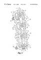
- FIG. 1is a top perspective view of an anterior plating system according to the present invention.
- FIG. 2is a top perspective view of the anterior plating system of FIG. 1 with the bone screws locked in place.
- FIG. 3is a top perspective view of the anterior plating system of FIG. 1 with bone screws translated in a slot of the plate.
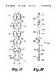
- FIGS. 4 ( a )-( f )are top plan views of fixation plates of the present invention provided in different sizes and configurations.
- FIGS. 5 ( a )-( 5 f )are top plan views of washers of the present invention provided in sizes and configurations corresponding to the plates in FIGS. 5 ( a )- 5 ( f ).
- FIG. 6is a side elevational view of a bone screw according to one aspect of the present invention.
- FIG. 7is a side elevational view of a locking fastener according to another aspect of the present invention.
- FIGS. 8 ( a )- 8 ( k )are various views and sections of washers according to the present invention.
- FIG. 9is a top plan view of a first end of the fixation plate of the present invention.
- FIG. 10is a cross-sectional view taken through line 10 — 10 of FIG. 9 .
- FIG. 11is an end elevational view of the plate of FIG. 9 .
- FIG. 12is a top plan view of a second end of the fixation plate of the present invention.
- FIG. 13is a cross-sectional view taken along line 13 — 13 of FIG. 12 .
- FIG. 14is an enlarged cross-sectional view taken through line 14 — 14 of FIG. 12 .
- FIG. 15is a top plan view of an intermediate portion of the fixation plate of the present invention.
- FIG. 16is a cross-sectional view taken through line 16 — 16 of FIG. 15 .
- FIG. 17is an enlarged cross-sectional view taken through line 17 — 17 of FIG. 15 .
- FIG. 18is an enlarged cross-sectional view taken through line 18 — 18 of FIG. 15 .
- FIG. 19 ais a partial sectional view of the anterior plate assembly of the present invention with the screws disposed through the holes at the first end of the plate and engaged in a vertebra.
- FIG. 19 bis a partial sectional view of the anterior plate assembly of the present invention with the screws disposed through the slots of the plate and engaged in a vertebra.
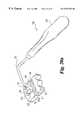
- FIGS. 20 ( a )- 20 ( f )illustrate various instruments and steps of a method according to another aspect to the present invention.
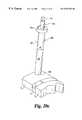
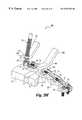
- FIGS. 21 ( a )- 21 ( c )are various perspective views of a compression tool according to yet another aspect of the present invention.
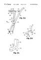
- FIGS. 22 ( a )- 22 ( b )are side elevational views of the arms of an alternate embodiment compression tool.
- FIGS. 1-3A plating system 30 having application in an anterior approach to the cervical spine is depicted in FIGS. 1-3.
- the portion of the spineis shown schematically in FIG. 1 to include a first vertebra V 1 , a second vertebra V 2 , and intermediate vertebrae V 3 and V 4 .
- first vertebra V 1is the inferior or bottom vertebra in the portion of the spinal column and the second vertebra V 2 is the superior or top vertebra of the portion of the spinal column.
- first vertebra V 1is the superior vertebra and that second vertebrae V 2 is the inferior vertebra.
- the present inventionhas application with spinal column portions that include vertebrae ranging in number from two to six vertebrae.
- Implant Imay be placed into one or more of the disc spaces between adjacent vertebrae as needed.
- Implant Imay be a bone graft, fusion device, or any other type of interbody device that is insertable into a disc space and promotes fusion between adjacent vertebrae.
- the plating system 30includes an elongated plate 31 having a number of openings therethrough and a number of bone engaging fasteners, shown in the form of bone screws 50 , that are insertable through the openings.
- each bone engaging fasteneris in the form of a bone screw.
- Plate 31has a longitudinal axis L extending along the length of the plate at its centerline. Bone engaging fasteners or bone screws 50 are held in plate 31 by way of a retainer assembly 33 positioned along axis L.
- the openings of elongated plate 31include a pair of holes 34 at first node 36 adjacent a first end of plate 31 . First node 36 is positioned over first vertebra V 1 .
- Plate 31also includes a pair of slots 35 at a second node 37 adjacent a second end of plate 31 .
- Second node 37is positioned over second vertebra V 2 .
- several intermediate nodes 38are provided along the length of the plate 31 between first node 36 and second node 37 .
- Each intermediate node 38includes a pair of intermediate slots 32 positioned over a corresponding one of the intermediate vertebrae V 3 and V 4 .
- Plating system 30can be fabricated from any type of biocompatible material.
- holes 34are paired with one of the holes of the pair on one side of the longitudinal axis L and the other hole of the pair on the opposite side of axis L.
- Slots 32 and 35are similarly arranged in pairs. It is also preferred that paired holes 34 are identical in shape and size, and are located symmetrically about the axis L. Paired slots 35 are also identical in shape and size, and are located symmetrically about the axis L. The paired slots 32 at intermediate nodes 38 are also identical in shape and size, and are located symmetrically about the axis L.
- Plate 31includes recesses between each of nodes 36 , 37 , 38 to reduce the outer contouring size of the plate.
- Plate 31has a length selected by the surgeon with nodes 36 , 37 , and, if needed, nodes 38 to register with the patient vertebrae.
- Plate 31preferably includes a rounded upper surface 41 that is in contact with the soft tissue surrounding the spine when the plate is engaged to the spine. Rounded surface 41 reduces the amount of trauma that would be experienced by the surrounding soft tissue.
- the bottom surface 42 of plate 31is preferably configured to contact the vertebral bodies of the spine at each of the instrumented levels. In one embodiment, at least a portion of bottom surface 42 can be textured along the length of the plate to enhance its grip on a vertebral body.
- Holes 34include a recess 45 adjacent the top surface of plate 31 that allow the head of the bone engaging fastener, such as bone screw 50 , to be countersunk in plate 31 .
- intermediate slots 32include a recess 46 around each slot 32 adjacent top surface of the plate
- slots 35include a recess 47 around each slot 35 adjacent the top surface of the plate.
- slots 35include a ramp 60 that, as described further below, allows a dynamic compression load to be applied to the spinal column portion upon insertion of screw 50 at second end 43 of slot 35 .
- Recesses 46 , 47also allow the head of screw 50 to be countersunk in plate 31 when inserted through a corresponding one of the slots 32 , 35 .
- a groove 39extends along axis L of plate 31 and intersects with each of recesses 45 , 46 , 47 along the length of groove 39 .
- the end of plate 31 at second node 37includes a notch 40 , which is preferably rounded with a radius R 4 centered on axis L (Fig, 12 .)
- Retainer assembly 33includes a washer 90 having a length that substantially corresponds to the length of plate 31 .
- Washer 90defines a plurality of apertures 91 .
- Each aperture 91is provided at a body portion 93 , 94 , 95 that corresponds to vertebral nodes 36 , 37 , 38 , respectively.
- a connecting portion 98extends between and connects body portions 93 , 94 , 95 .
- Each of the apertures 91has a countersink 92 extending therearound adjacent to the top surface of washer 90 .
- countersink 92is tapered from a first width at the first end of aperture 91 to a second width at the second end of aperture 91 , the first width being greater than the second width.
- Locking fastenersshown in the form of screws 85 , are positionable, each through a corresponding one of the apertures 91 , to engage a fastener bore 70 (see FIGS. 4 ( a )- 4 ( f )) in plate 31 and couple washer 90 to plate 31 .
- Washer 90is translatable from an unlocked position (FIG. 1) for bone screw insertion to a locked position (FIG. 2) after screw insertion to contact the head of the bone screws in holes 34 and overlap the heads of bone screws in slots 32 , 35 .
- washer 90does not contact the heads of bone screws in slots 32 , 35 , thus allowing translation of the bone screws in the slots.
- Back-out of the bone screws in slots 32 , 35is prevented when the bone screw backs out from its seated position a sufficient amount to contact washer 90 .
- washer 90resides almost entirely within groove 39 of plate 31 to minimize the overall height of the construct.
- retainer assembly 33is in an unlocked condition with screws 85 at the second end of apertures 90 .
- body portions 93 , 94 , 95 of washer 90do not overlap holes 34 and a portion of slots 32 , 35 , and enable insertion of the bone screws 50 therein.
- Narrowed portions 98 of washer 90allow bone screws 50 to be placed through holes 34 and slots 35 to secure plate 31 to the vertebrae V 1 and V 2 .
- the surgeoncan also place bone screws 50 in intermediate slots 32 to secure plate 31 to vertebrae V 3 and V 4 as deemed necessary.
- Plate 31 and bone screws 50preferably interface in holes 34 such that rigid fixation of plate 31 to the first vertebra V 1 is achieved.
- Slots 35are positioned over second vertebra V 2 , and include a second end 43 and a first end 44 . As shown in FIG. 1, screw 50 is initially is inserted at second end 43 of slot 35 , allowing subsequent translation of screw 50 in slot 35 from second end 43 to first end 44 . For the purposes of clarity, only a single screw 50 is shown in slot 35 ; however, it is contemplated that bone screws are inserted in both slots 35 . Bone screws 50 inserted in intermediate slots 32 also translate from the second end 48 to first end 49 (FIG. 15) of slot 32 .
- washer 90 of retainer assembly 33may be translated to its locked condition shown in FIG. 2 .
- body portions 93 , 94 , 95 of washer 90retain the heads of the inserted screws 50 in holes 34 and slots 32 , 35 and prevent the screws from backing out of plate 31 .
- locking screw 85is threaded into a corresponding fastener bore 70 in plate 31 . This downward threading of locking screw 85 causes the tapered countersink 92 of washer 90 to ride along the head of locking screw 85 until locking screw 85 contacts the first end of aperture 91 . This translates washer 90 along axis L to its locked condition, where the washer 90 retains bone screws 50 in plate 31 .
- Bone screws 50are allowed to translate within slots 35 and intermediate slots 32 from the second end of the slots to the first end of the slots while retainer assembly 33 retains bone screws 50 in plate 31 and prevents screw backout. As shown in FIG. 3, the screw positioned in slot 35 has translated from second end 43 to first end 44 . The translation of screw 50 is limited by contact of screw 50 with first end 44 . The amount of translation may also be controlled by providing bone screws in intermediate slots 32 . Thus, the amount of translation of the spinal column segment can be limited by the length of slots 32 , 35 .
- FIGS. 4 ( a )- 4 ( f ) and FIGS. 5 ( a )- 5 ( f )several embodiments of elongated plate 31 and washer 90 are depicted.
- the anterior plating system 30can be readily adapted for fixation to several vertebrae by modifying the length of plate 31 and the number and arrangements of holes 34 , second slots 35 , and intermediate slots 32 .
- Paired slots 32 , 35 and paired holes 34 at each of the vertebraeprovide, at a minimum, for at least two bone screws 50 to be engaged into each respective vertebrae. The placement of two or more screws in each vertebral body improves the stability of the construct.
- the present inventioncontemplates various specific embodiments for a plate 31 that is provided in lengths that range from 19 millimeters (hereinafter “mm”) to 110 mm, and an overall width of about 17.8 mm. However, other dimensions for the length and width of plate 31 are also contemplated herein.
- the plate 31 of FIGS. 1-3is sized to span four vertebrae and includes a first node 36 , a second node 37 , and two intermediate nodes 38 .
- plate 31 a and washer 90 aare sized span two vertebrae.
- Plate 31 ahas holes 34 a at first node 36 a and holes 34 a at second node 37 a .
- Plate 31 ais provided with washer 90 a that resides in groove 39 a and is translatable to retain bone screws in holes 34 a .
- plate 31 aprovides rigid fixation at each vertebra.
- a modification of plate 31 ais depicted FIGS. 4 ( b ) and 5 ( b ).
- the holes at the second vertebral nodeare replaced with slots 35 b at second node 37 b .
- a washer 90 bresides in groove 39 b and is translatable to retain bone screws in holes 34 b and slots 35 b.
- Plate 31 c and washer 90 c of FIGS. 4 ( c ) and 5 ( c )similarly provide for instrumentation at two vertebrae.
- Plate 30 chas a recess portion between nodes 36 c and 37 c .
- Washer 90 cresides in groove 39 c and is translatable to retain lock screws in holes 34 c and slots 35 c .
- the plates of FIGS. 4 ( a )- 4 ( c )span two vertebrae, and preferably do not include notch 40 on the second end of that plate as do the plates sized to span three or more vertebrae.
- Plate 31 d and washer 90 d of FIGS. 4 ( d ) and 5 ( d )are provided for instrumentation at three vertebrae.
- Plate 31 dhas first vertebral node 36 d , second vertebral node 37 d , and intermediate node 38 d .
- Washer 90 dresides in groove 39 d and is translatable to retain bone screws in holes 34 d and slots 32 d , 35 d .
- Plate 31 e and washer 90 e of FIGS. 4 ( e ) and 5 ( e )are provided for instrumentation at five vertebrae.
- Plate 31 ehas first vertebral node 36 e , second vertebral node 37 e , and three intermediate nodes 38 e .
- Washer 90 eresides in groove 39 e and is translatable to retain bone screws in holes 34 e and slots 32 e , 35 e .
- Plate 31 f and washer 90 f of FIGS. 4 ( f ) and 5 ( f )are provided for instrumentation at six vertebrae.
- Plate 31 fhas first vertebral node 36 f , second vertebral node 37 f , and four intermediate nodes 38 f .
- Washer 90 fresides in groove 39 f and is translatable to retain bone screws in holes 34 f and slots 32 f , 35 f.
- Bone screw 50is preferably configured for engagement in the cervical spine, and includes threaded shank 51 that is configured to engage a cancellous bone of the vertebral body.
- the threaded shankmay be provided with self-tapping threads, although it is also contemplated that the threads can require prior drilling and tapping of the vertebral body for insertion of screw 50 .
- the threads on shank 51define a constant outer diameter d2 along the length of the shank.
- shank 51has a root diameter that is tapered along a portion of the length of the shank and increases from the tip of shank 51 to a diameter d1 at an intermediate or cylindrical portion 52 .
- Intermediate portion 52extends between shank 51 and a head 54 of screw 50 .
- the threads on shank 51extend into portion 52 by a thread run out 53 .
- cylindrical portion 52includes a short segment that does not bear any threads. This segment of cylindrical portion 52 interfaces or contacts with a plate thickness at hole 34 or slot 32 , 35 through which bone screw 50 extends. This short segment has an outer diameter d1.
- the head 54 of screw 50includes a tool recess 55 configured to receive a driving tool.
- tool recess 55is a hex recess, or in the alternative, any type of drive recess as would occur to those skilled in the art.
- Head 54includes a truncated or flattened top surface 56 having a diameter d4.
- a spherical surface 57extends from cylindrical portion 52 to a shoulder 59 .
- Shoulder portion 59has a diameter d 5 .
- An inclined surface 58extends between shoulder 59 and truncated top surface 56 .
- Inclined surface 58forms an angle A I with top surface 56 .
- screw 50may be provided with shank 51 having a length that varies from about 10 mm to about 24 mm.
- the threadshave diameter d2 of about 4.5 mm.
- the diameter d2is about 4.0 mm.
- cylindrical portion 52has a diameter d1 of about 4.05 mm.
- Cylindrical portion 52has an unthreaded segment with a height h1 that is determined by standard machining practices for thread run-out between a shank and screw head. Height h1 and diameter d1 of cylindrical portion 52 are sized to achieve a snug fit between screw 50 and plate 31 in hole 34 or slot 32 , 35 through which screw 50 is placed.
- Head 54is provided with height h2, outer diameter d5 at shoulder 59 , diameter d4 at top surface 56 , and inclined surface 54 angle A I such that the head 54 is nested within its corresponding slot 32 , 35 or hole 34 and recessed below the top surface of the plate.
- height h2outer diameter d5 at shoulder 59 , diameter d4 at top surface 56 , and inclined surface 54 angle A I such that the head 54 is nested within its corresponding slot 32 , 35 or hole 34 and recessed below the top surface of the plate.
- Locking screw 85includes a shank 86 having machine threads thereon. In one specific embodiment, locking screw 85 terminates in a sharp point 88 that permits penetration into the vertebral body when locking screw 85 is secured in threaded fastener bore 70 .
- Head 87includes a lower conical surface 89 configured to mate with aperture 91 of washer 90 . Head 87 further includes a tool recess 87 a for receiving a driving tool therein.
- Washer 90includes second body portion 95 , first body portion 93 , and if necessary, one or more intermediate body portions 94 .
- a connecting portion 98extends between and connects each of the body portions 93 , 94 , 95 .
- Washer 90has a top surface 100 a and a bottom surface 100 b .
- Each body portion 94 , 95defines an aperture 91 extending between top surface 100 a and bottom surface 100 b .
- Aperture 91has a tapered countersink portion 92 therearound adjacent top surface 100 b .
- Aperture 91allows passage of shank 86 of locking screw 85 therethrough, and countersink 92 is preferably configured to mate with conical surface 89 and seat locking screw 85 at various positions along the length of aperture 91 .
- countersink portion 92is sloped toward bottom surface 100 b from second end 97 to first end 96 .
- the mating conical features between locking screw 85 and aperture 91provide a self-translating capability for washer 90 relative to plate 31 as locking screw 85 is tightened into fastener bore 70 of plate 31 .
- Body portions 93 , 94 , 95have a width W1 that is greater than a width W2 of connecting portion 98 .
- the width W1 and length of body portions 93 , 94 , 95are configured so that the body portions overlap with recess 45 of holes 34 and recesses 46 , 47 of slots 32 , 35 .
- the body portions 93 , 94 , 95retain the heads of bone screws extending through the holes and slots of plate 31 when washer 90 resides in groove 39 and is in the locked condition of FIG. 2 .
- the width W2 and the length of the connecting portions 98are configured to allow insertion of screws in holes 34 and slots 32 , 35 when washer 90 is in the unlocked condition of FIG. 1 .
- FIGS. 8 ( a ) and 8 ( b )there is shown second body portion 95 of washer 90 .
- Aperture 91has countersink portion 92 that is tapered along the length of aperture 91 .
- Aperture 91has a width W3 at bottom surface 100 b of washer 90 .
- Countersink portion 92has a width that varies along the length of aperture 91 and is greater than width W3.
- Countersink portion 92has a radius R1 at second end 97 and a radius R2 at first end 96 at top surface 100 a . It is preferred that R1 is less than R2 and the width of countersink portion 92 increases from second end 97 towards first end 96 .
- Aperture 91has a chord length S1 extending between the center of radius R1 and the center of radius R2.
- Body portion 95further includes a transition portion 99 that extends between connecting portion 98 and body portion 95 .
- Intermediate body portion 94 of FIGS. 8 ( c ) and 8 ( d )is similar in many respects to second body portion 95 of FIGS. 8 ( a ) and 8 ( b ), and also includes an aperture 91 having a tapered countersink portion 92 .
- intermediate body portion 94has a connecting portion 98 extending in both directions therefrom.
- a second transition portion 98 aextends between second connecting portion 98 and body portion 94 .
- Body portion 94has a chord length S1 between the center of radius R1 and the center of radius R2.
- Tapered countersink 92 of aperture 91provides a self-translating capability of the washer 90 . This is because the washer 90 is translated relative to plate 31 as the locking screw 85 is threaded into threaded bore 70 .
- the camming conical surface 89 of screw 85advances downward along the tapered portion of the wall of countersink portion 92 of aperture 91 .
- FIGS. 8 ( e ) and 8 ( f )show first body portion 93 .
- First body portion 93is also similar to second body portion 95 .
- first body portion 93includes an aperture 91 ′ having a countersink portion 92 ′ that is not tapered along its length to provide a self-translating capability for washer 90 like the countersink portions 92 of body portions 94 and 95 . Rather, after washer 90 is translated relative to plate 31 as described above, locking screw 85 will already be positioned at first end 96 ′, and may thereafter be threaded into bore 70 and seated within countersink portion 92 ′.
- the surgeonmay slide the washer by hand or with a tool to its translated position, and lock the washer in its translated position by seating locking screw 85 into countersink 92 ′ at first end 96 ′.
- Countersink 92 ′has a definite location at second end 96 ′ for seating locking screw 85 , providing a reference for the surgeon to confirm that washer 90 has been translated to its locked position.
- body portion 93could also be provided with aperture 91 like body portions 94 and 95 as shown in FIGS. 1-3.
- Washer 90has an outer surface 104 configured to overlap bone screws 50 in slots 32 , 35 without contacting inclined surface 58 of screws 50 when retainer assembly 33 is in its locked condition.
- Outer surface 104extends from bottom surface 100 b to a shoulder 103 .
- Shoulder 103extends between inclined surface 104 and top surface 100 a .
- Inclined surface 104forms an angle A 2 with respect to bottom surface 100 b .
- Washer 90defines a thickness t1 between top surface 100 a and bottom surface 100 b , and a shoulder height of t2 from bottom surface 100 b .
- Washer 90has a width W7 along bottom surface 100 b at aperture 91 .
- Washer 90has contact surface 106 configured to contact inclined surface 58 of screws 50 when retainer assembly 33 is in its locked condition.
- Contact surface 106extends from bottom surface 100 b to a shoulder 105 .
- Shoulder 105extends between contact surface 106 and top surface 100 a .
- Contact surface 106forms an angle A 3 with respect to bottom surface 100 b that is configured to mate with and provide surface contact with inclined surface 58 of bone screw 50 .
- Washer 90defines a thickness t3 between top surface 100 a and bottom surface 100 b , and a shoulder height of t4 from bottom surface 100 b.
- the body portionshave a width W1 and connecting portion have width W2 that is based on the spacing between the centerlines of the paired slots and holes of the plates and the overall width of the plate.
- the width W3 of aperture 91 in the specific embodimentis sized to accommodate the shank 86 of locking screw 85 without head 87 passing therethrough.
- the length of body portions 94 and 95varies based on the length and spacing between slots 32 , 35 and holes 34 in plate 31 .
- the body portions 94 , 95have a length sufficient to overlap substantially the entire length of slot 32 , 35 when retainer assembly 33 is in its locked position.
- the tapered countersink portion 92 of aperture 91has radius R1 that transitions to radius R2 along the chord length S1.
- Thickness t1is less than thickness t3, and shoulder height t4 is less than shoulder height t2.
- Body portion 93has a width W8 along bottom surface 100 b that is greater than width W7 of body portions 94 , 95 .
- Angle A 2is preferably less that angle A 1 .
- the dimensions of washer 90are preferably arranged so that body portions 94 , 95 do not contact the screw heads nested in slots 32 , 35 to facilitate translation of the screws in slots 32 , 35 .
- Body portion 93contacts the screw heads nested in holes 34 to further enhance the fixed orientation between screws 50 and plate 31 in holes 34 .
- the present inventionalso contemplates a retainer assembly in which individual washers are provided at each node for retaining screws in holes 34 and slots 32 , 35 of plate 31 .
- a slot washer 195 and a hole washer 193are provided.
- Slot washer 195is similar to body portion 95 of washer 90 and hole washer 193 is similar to body portion 93 of washer 90 , both of which are described above. Elements that are alike bear the same reference number as the corresponding element of body portions 95 , 93 .
- Slot washer 195 and hole washer 193do not have a connecting portion 98 extending to another washer.
- Slot washer 195has a body portion 198 with a length S2 that varies and is sized to correspond to the length of the adjacent slot 32 , 35 when washers 195 are positioned on plate 31 . Slot washer 195 does not have a connecting portion 98 extending to another washer.
- Hole washer 193has a body portion 199 with a length S3 that varies and is sized to correspond to the length of the plate adjacent hole 34 when washer is positioned on plate 31 .
- FIG. 8 ( k )an alternate embodiment of washers 193 and 195 is provided and designated at 193 ′, 195 ′ respectively.
- Washers 193 ′, 195 ′are the same as washers 193 , 195 described above, except for aperture 191 .
- Aperture 191does not have a tapered countersink, but rather has a semi-circular countersink portion 192 only at first end 196 .
- Countersink portion 192provides a single position for locking screw 85 to lock the washer 193 ′, 195 ′ to plate 31 after the washer 193 ′, 195 ′ has been translated relative to plate 31 by the surgeon.
- Washers 193 ′, 195 ′have body portion 198 ′, 199 ′ with length S 4 that varies as described above with respect to length S2 and S3.
- first node 36 of plate 31is depicted. It is preferred that holes 34 are identical and symmetrical about axis L. Hole 34 includes recess 45 adjacent top surface 41 . Holes 34 include a cylindrical bore 77 having generally vertical sidewalls adjacent bottom surface 42 . Cylindrical bore 77 extends between recess 45 and bottom surface 42 of plate 31 , and has a diameter D1. Cylindrical bore 77 has axis 72 b that is offset at angle A 5 from an axis 72 a that extends normal to plate 31 as shown in FIG. 10 .
- Recess 45has a partial spherical portion 45 a defined about a central axis 72 b .
- Axis 72 bis offset from axis 72 a by angle A 5 . Offset angle A 5 directs bone screws inserted into holes 34 toward the first end of plate 31 .
- axes 72 aconverge below the bottom surface 42 of plate 31 at angle A 4 with respect to an axis 72 c that extends along the centerline of plate 31 perpendicular to axis L.
- Recess 45intersects groove 39 at intersecting portion 45 c .
- Spherical portion 45 ais configured to mate with spherical surface 57 of bone screw 50 , allowing at least a portion of head 54 to be recessed below top surface 41 of plate 31 .
- recess 45also includes a flared portion 45 b that extends in a superior direction from axis 72 b .
- recess 45includes a wall that parallels bore 77 and extends between between spherical portion 45 a and flared portion 45 b to further facilitate insertion and maintenance of a drill guide in recess 45 .
- spherical portion 45 ahas a diameter that mates with the diameter of spherical surface 57 of screw 50 , and is slightly larger than diameter d5 of head 54 of bone screw 50 .
- the cylindrical bore 77 of hole 34has a diameter D1 of 4.1 mm, which is slightly larger than the diameter d1 of intermediate portion 52 of screw 50 . This portion of the screw contacts bore 77 and assumes a fixed orientation with respect to plate 31 .
- offset angle A 5is about 12.6 degrees and convergence angle A 4 is about 6 degrees relative to axis 72 c .
- Vertebral node 37includes slots 35 that are preferably identical and symmetrical about axis L.
- Slot 35includes slotted bore 78 adjacent bottom surface 42 of plate 31 having generally vertical sidewalls extending between second end 43 and first end 44 .
- Slotted bore 78extends between bottom surface 42 and recess 47 adjacent top surface 42 .
- Bore 78has a width W5 and a chord length S4, and has a central axis 75 b extending through plate 31 .
- Recess 47has a spherical portion 47 a about central axis 75 b that extends around slot 35 . As shown in FIG.
- central axis 75 bis offset from axis 75 a that extends normal to plate 31 by angle A 5 . Offset angle A 5 directs bone screws inserted into slot 35 towards the second end of plate 31 .
- slot 35allows insertion of a bone screw at angles less than A 5 in slot 35
- bone screw 50may be positioned within slot 35 at any location between ends 43 and 44 .
- retaining assembly 33provides for insertion of bone screws 50 at second 43 as would be clinically desirable for settling.
- axes 75 bconverge below the bottom surface 42 of plate 31 at angle A 4 with respect to axis 72 c.
- Spherical portion 47 ais configured to mate with spherical surface 57 of bone screw 50 , allowing at least a portion of head 54 to be recessed below top surface 41 of plate 31 .
- recess 47also includes a flared portion 47 b that extends around spherical portion 47 a .
- recess 47include a wall that parallels bore 78 extending between spherical portion 47 a and flared portion 47 b to further facilitate maintenance and insertion of a drill guide in recess 47 .
- Recess 47intersects groove 39 at overlap portion 47 c , as shown in FIG. 14 .
- the second end of second node 37includes notch 40 having radius R4 centered about axis L. It is also contemplated herein that plate 31 is provided without notch 40 , as shown in FIGS. 4 ( a )- 4 ( c ).
- slot 35includes ramp 60 extending between bore 78 and flared portion 47 b at second end 43 .
- Ramp 60is not configured to allow spherical surface 57 of screw 50 to seat therein, but has an orientation that causes second end 43 of slot 35 and screw 50 to separate as screw 50 is threaded into slot 35 .
- Spherical surface 57 of head 54provides camming action along the ramp 60 until head 54 seats in recess 47 at a position spaced a distance from second end 43 . This camming action applies a dynamic compression load to the spinal column portion. The amount of compression applied to the spinal column portion is controlled by the length of ramp 60 from second 43 to the position in slot 35 where screw 50 seats in recess 47 . It should be understood that slot 35 may also be provided without ramp 60 .
- spherical portion 47 ahas a diameter sized to mate with spherical surface 57 of screw 50 , and is slightly larger than diameter d5 of head 54 of bone screw 50 .
- Slotted bore 78has a width W5 of about 4.1 mm, which is slightly larger than the diameter d1 of intermediate portion 52 of screw 50 .
- the cylindrical portion 52 of bone screw 50contacts plate 31 in bore 78 and prevents rotation of screw 50 transverse to axis 72 c .
- the chord length S4varies depending upon the length of the slot 35 needed for the particular application of plate 31 and patient anatomy.
- offset angle A 5is about 12.6 degrees and convergence angle A 4 is about 6 degrees relative to an axis 72 c .
- Vertebral node 38includes slots 32 that are preferably identical and symmetrical about axis L.
- Slot 32includes slotted bore 79 adjacent bottom surface 42 of plate 31 having generally vertical sidewalls extending between a second end 48 and a first end 49 .
- Slotted bore 79extends between bottom surface 42 and recess 46 adjacent top surface 42 .
- Bore 79has a width W5 and a chord length S5, and has a central axis 76 a extending through plate 31 .
- Recess 46has a spherical portion 46 a that extends around slot 35 . As shown in FIG. 16, central axis 76 a generally extends normal to plate 31 .
- the axes 76 aconverge below the bottom surface 42 of plate 31 at angle A 4 with respect to axis 72 c . It should be noted that slot 32 allows insertion of bone screws 50 at various angles with respect to axis 76 a.
- Spherical portion 46 ais configured to mate with spherical surface 57 of bone screw 50 , allowing at least a portion of head 54 to be recessed below top surface 41 of plate 31 .
- recess 46also includes a flared portion 46 b that extends around spherical portion 46 a .
- a wall paralleling bore 79extends between spherical portion 46 a and flared portion 46 b to further facilitate insertion and maintenance of a drill guide in recess 46 .
- Screw 50may be placed within intermediate slot 32 between ends 48 and 49 . However, it is preferred that the screw is inserted initially at second end 48 , thus allowing compression loading of the spinal column segment.
- Recess 46intersects groove 39 at overlap portion 46 c , as shown in FIG. 17 .
- spherical portion 46 ahas a diameter sized to mate with spherical surface 57 of screw 50 , and is slightly larger than diameter d5 of head 54 of bone screw 50 .
- the slotted bore 79has a width W5 of about 4.1 mm, which is slightly larger than the diameter d1 of intermediate portion 52 of screw 50 .
- Cylindrical portion 52 of bone screw 50interfaces with plate 31 in bore 79 such that angular adjustment of screw 50 transverse to axis 72 c is prevented.
- the chord length S5varies depending upon the length of slot 35 needed for the particular application of plate 31 and patient anatomy.
- convergence angle A 4is about 6 degrees relative to an axis 72 c .
- Groove 39has a width W6 at top surface 41 of plate 31 .
- Groove 39has bottom surface 73 extending between inclined sidewalls 74 .
- Sidewalls 74extend between bottom surface 73 of groove 39 and top surface 41 of plate 31 . It is contemplated that the groove 39 has a depth sufficient to accommodate the washer 90 so as to minimize protrusion of washer 90 above top surface 41 of plate 31 .
- the plateis curved in two degrees of freedom.
- the bottom surface 42 of the platecan be curved along a large radius R, centered in a vertebral plane containing central axis L, as shown schematically in FIG. 16, to accommodate the lordotic curvature of the cervical spine.
- bottom surface 42forms a medial/lateral curvature C, as shown in FIG. 18, to correspond to the curvature of the vertebral body.
- plate 31can also be bent as needed to accommodate the particular spinal anatomy and vertebral pathology.
- FIG. 19 aa partial sectional view of fixation plate assembly 30 at holes 34 is provided with screws 50 engaged to vertebra V 1 and retainer assembly 33 in the locked position.
- a pair of screws 50are disposed within the respective holes 34 so that the threaded shanks 51 project beyond the lower surface 42 of plate 31 into the vertebral body V 1 .
- the intermediate portion 52 of screw 50extends through the bore 77 of the hole 34 .
- Spherical surface 57 of head 54contacts recess 45 of hole 34 when screw 50 is seated therein.
- the intermediate portion 52provides a snug fit for screw 50 in the bore 77 so that screw 50 is not able to pivot with respect to plate 31 .
- FIG. 19 ba partial sectional view of fixation plate assembly 30 at slots 32 or 35 is provided with screws 50 engaged to vertebra V 1 and retainer assembly 33 in the locked position.
- a pair of screws 50are disposed within respective slots 32 , 35 so that threaded shanks 51 project beyond lower surface 42 of plate 31 into the corresponding vertebral body V 2 , V 3 , or V 4 .
- Cylindrical portion 52 of screw 50extends through bores 78 , 79 of slots 35 and 32 , respectively.
- Spherical surface 57 of head 54contacts recesses 46 , 47 of slots 32 , 35 when screw 50 is seated therein.
- Cylindrical portion 52provides a snug fit for screw 50 in bores 78 , 79 so that screw 50 is not able to pivot or translate with respect to axis 72 c of plate 31 .
- screws 50 inserted into slots 32 or 35are able to translate along the length of slots 32 , 35 as described above. It should be understood that the present invention also contemplates various embodiments of plate 31 that use variable angle screws capable of assuming universal angular orientation with respect to plate 31 in slots 32 , 35 and holes 34 .
- retainer assembly 33is moved to its locked position where it contacts the heads 54 of bone screws 50 in holes 34 .
- Locking screw 85is threaded into threaded fastener bore 70 of plate 31 to translate washer 90 from its unlocked position to its locked position, as described above, and to draw contact surface 106 into contact with inclined surface 58 of screw 50 as shown in FIG. 19 a .
- Contact surface 106preferably applies a downward force onto head 54 to firmly seat the screw heads within the plate recesses and further fix screw 50 in hole 34 . In a preferred embodiment, this downward force is exacted by washer 90 as surface 106 contacts inclined surface 58 . As shown in FIG.
- outer surface 104 of washer 90does not contact the heads of bone screws 50 in slots 32 , 25 .
- Outer surface 104overlaps the bone screws 50 to retain bone screws in slots 32 , 35 .
- Outer surface 104will contact the heads of the bone screws if the bone screws backout from slots 32 , 35 . It is preferred that bottom surface 100 b of washer 90 does not contact bottom surface 73 of groove 39 .
- the retainer assembly 33may be loosely fixed on plate 31 so the surgeon need not fiddle with applying retainer assembly 33 to plate 31 during surgical procedures.
- the locking fasteners 85are pre-inserted through apertures 91 of washer 90 and partially threaded into fastener bores 70 .
- Washer 90is initially positioned such that the second end of each aperture 91 is positioned adjacent locking screw 85 .
- locking fasteners 85are advanced further into bores 70 and along tapered portions 92 of apertures 91 to translate washer 90 to a locked condition and retain bone screws 50 in plate 31 .
- sharp point 88 of locking screw 85is preferably configured to penetrate the cortical bone.
- sharp point 88will penetrate the vertebra when plate 31 is initially positioned on the bone.
- locking screw 85helps locate and temporarily stabilize the plate on the vertebra as the bone screws 50 are engaged to the vertebra. This temporary location feature provided by locking screw 85 can also be used to maintain the position of plate 31 on the vertebra as a drill guide is used to drill and tap the vertebrae to receive bone screws 50 .
- a guide 150includes a handle 152 , a template 154 , and arm 153 extending therebetween.
- arm 153extends outward from the spine and is bent so that handle 152 parallels the spine, positioning handle 152 out of the way of the surgeon.
- Template 154includes a second end 155 that defines a notch 158 .
- Template 154also includes first end 156 having a projection 156 a extending downward therefrom towards vertebral body V 2 .
- Template 154further defines a pair of slots 157 between second end 159 and first end 156 .
- the surgeonselects a guide 150 with a template 154 sized to position notch 158 at the desired location on vertebra V 2 and places guide instrument 150 on vertebral body V 2 .
- Notch 158is located on vertebra V 2 by placing projection 156 a in abutting contact with the endplate of vertebra V 2 in disc space D.
- Slots 157provide a visual indication to the surgeon of the range of positions available for screw insertion into the vertebral body through slots 35 of plate 31 . If desired, the surgeon can obtain a desired position or location of notch 158 and the desired available range of bone screw positions on vertebra V 2 by selecting a guide having a different sized template 154 .
- Pin 170is placed into vertebra V 2 guided by notch 158 .
- Pin 170includes a lower end 171 having a threaded portion (not shown) for attaching pin 170 to vertebra V 2 .
- the attachment portionis preferably threaded to screw into vertebra V 2 , but may also be smooth with a spiked tip for insertion into the vertebra.
- Pin 170also includes tool engagement portion 172 to facilitate installation of pin 170 to the vertebral body. It is also contemplated that the surgeon can place pin 170 on the vertebral body spaced away from notch 158 if desired and the vertebral anatomy so allows.
- Sleeve 180has a hollow body 181 extending between a first end 186 adjacent vertebra V 1 and a second end 184 .
- a second end 174 of pin 170preferably extends from second end 184 of sleeve 180 , allowing access to pin 170 .
- Sleeve 180includes enlarged portion 184 to facilitate placement and removal of sleeve 180 . It is contemplated that sleeve 180 has hollow interior and an internal configuration that provides secure attachment to pin 170 .
- Body 181includes cylindrical outer surface 182 with an outer diameter d6.
- plate 31With sleeve 180 in its proper position, plate 31 is positioned with notch 40 in abutting contact with outer surface 182 of sleeve 180 , as shown in FIG. 20 ( d ).
- the diameter d6 of sleeve 180slightly less than the twice the radius of notch 40 so that notch 40 is nested around sleeve 180 .
- Plate 31is then secured to vertebra V 1 by inserting screws 50 through holes 34 .
- gap 177is about 2 mm. However, other sizes for gap 177 are contemplated herein based on the desired compression to be applied.
- a compression tool 290is secured to pin 170 and to slots 32 of plate 31 . It is also contemplated that the compression tool can be secured to plate 31 other than at slots 32 by, for example, engaging the sides of plate 31 .
- Compression tool 290has a first arm 291 with a first foot 294 connected to pin 170 . Second arm 292 is connected to the second end of slots 32 via extensions 297 extending from second foot 296 . First arm 291 and second arm 292 are manipulated by the surgeon to apply a compression load to the spinal column segment. The amount of applied load is limited by gap 177 between pin 170 and notch 40 . For example, in the specific embodiment where gap 177 is 2 mm, the spinal column portion is compressed 2 mm.
- Bone screws 50are inserted into slots 35 with compression tool 290 maintaining the compression load. With ramp 60 at second 43 of slot 35 , an additional amount of dynamic compression is achieved with screw insertion in slots 35 , as described above. With screws 50 seated at end 43 of slots 35 , compression tool 290 may be removed without release of the compression load. Additional bone screws may be inserted into intermediate slots 32 . Washer 90 may then be translated as described above to retain bone screws 50 in plate 31 . It should be note that it is contemplated herein that compression tool 290 and pin 170 are preferably only used with plates providing instrumentation at three or more vertebra. However, utilization of a compression tool configured to engage a plate for providing instrumentation at two vertebrae is not precluded.
- Tool 290has first arm 291 having first foot 294 extending therefrom.
- First foot 294defines recess 293 for receiving the pin 170 .
- Second arm 292has second foot 296 extending therefrom.
- Second foot 296includes extensions 297 extending downward therefrom configured to engage intermediate slots 32 of plate 31 .
- Extensions 297preferably include recesses 307 that are configured contact the second ends of intermediate slots 32 . It is also contemplated that extensions 297 have a curved bottom surface 308 that corresponds to the medial lateral curvature of the vertebral bodies.
- First arm 291has a reduced thickness portion 299 extending through a passage 295 formed in second arm 292 , and is pivotally coupled to second arm 292 with pin 299 .
- First arm 291has curved handle portion 306 having a projection 303 extending therefrom.
- Second arm 292has a handle 305 .
- a ratchet bar 301is pivotally coupled to second arm 292 via coupling 302 .
- ratchet bar 301is spring-biased towards projection 303 .
- Serrations 304 formed on the bottom side of ratchet mechanism 301provide for selective engagement with projection 303 on first arm 291 .
- the first and second armsare compressed towards one another to apply the compressive load to the vertebral segment.
- Projection 303engages the serrated bottom of ratchet bar 301 to prevent relaxation of the arms and allows the surgeon to maintain the compression load during insertion of bone screws 50 within slots 35 .
- Ratchet bar 301may be lifted against its spring bias away from arm 291 to disengage ratchet bar 301 from projection 303 .
- Arms 291 , 292may then be moved away from one another to release compression tool 290 from pin 170 and plate 31 .
- compression tool 290has been illustrated and described in detail, the present invention also contemplates other tools capable of being secured between pin 170 and plate 31 to provide a compression load to the spinal column segment.
- a compression toolmay include one or more angular modifications to first arm 391 and second arm 392 to facilitate access to plate 31 and pin 170 at the surgical site.
- First arm 391has a lower portion 391 a forming angle B 1 with first foot 396 .
- First foot 396has extensions 397 extending therefrom that are similar to extensions 297 of tool 290 .
- First armhas an upper portion 391 c that terminates with curved handle 406 .
- Curved handle 406has projection 403 extending therefrom to engage a ratchet bar extending from second arm 392 .
- Arm 391has a vertical extension 391 b extending between lower portion 391 a and upper portion 391 c .
- Angle B 2is formed between lower portion 391 a and vertical portion 391 b .
- Angle B 1is formed between vertical portion 391 b and upper portion 391 c .
- Vertical portion 391 bas a region of reduced thickness 399 for connection with second arm 392 .
- Second arm 392has a lower portion 392 a forming angle B 1 with second foot 394 .
- Second foot 394has a recess (not shown) for receiving pin 170 and is similar to recess 293 of tool 290 described above.
- Second arm 392has an upper portion 392 c that terminates with handle 405 .
- Upper portion 392 chas ratchet bar 401 with serrations 404 .
- Ratchet bar 401is pivotally coupled to arm 392 and spring-biased towards projection 403 .
- Ratchet bar 401is similar to ratchet bar 301 , but is preferably curved along its length to accommodate the angular offsets in arms 391 , 392 while maintaining engagement between ratchet bar 401 and projection 403 .
- Arm 392has a vertical extension 392 b extending between lower portion 392 a and upper portion 392 c .
- Angle B 2is formed between lower portion 392 a and vertical portion 392 b .
- Angle B 1is formed between vertical portion 392 b and upper portion 392 c .
- Vertical portion 392 bas a slot 395 of receiving reduced thickness portion 399 of vertical portion 391 b , where first and second arms are pivotally coupled via a pin (not shown.)
- angle B 1is about 120 degrees and angle B 2 is about 150 degrees.
- other angular offsets in first and second arms of compression tools 190 , 290are also contemplated herein as would occur to those skilled in the art.
Landscapes
- Health & Medical Sciences (AREA)
- Orthopedic Medicine & Surgery (AREA)
- Surgery (AREA)
- Life Sciences & Earth Sciences (AREA)
- Molecular Biology (AREA)
- Public Health (AREA)
- Engineering & Computer Science (AREA)
- Biomedical Technology (AREA)
- Heart & Thoracic Surgery (AREA)
- Medical Informatics (AREA)
- Neurology (AREA)
- Animal Behavior & Ethology (AREA)
- General Health & Medical Sciences (AREA)
- Nuclear Medicine, Radiotherapy & Molecular Imaging (AREA)
- Veterinary Medicine (AREA)
- Dentistry (AREA)
- Oral & Maxillofacial Surgery (AREA)
- Surgical Instruments (AREA)
- Prostheses (AREA)
- External Artificial Organs (AREA)
- Pharmaceuticals Containing Other Organic And Inorganic Compounds (AREA)
- Polishing Bodies And Polishing Tools (AREA)
Abstract
Description
The present invention relates generally to the field of instrumentation and systems for the spine, and more particularly to instrumentation and systems for use in treatment of various pathologies of the cervical spine.
As with any bony structure, the spine is subject to various pathologies that compromise its load bearing and support capabilities. Such pathologies of the spine include, for example, degenerative diseases, the effects of tumors and, of course, fractures and dislocations attributable to physical trauma. Spinal surgeons have addressed these problems using a wide variety of instrumentation in a broad range of surgical techniques. The use of elongated rigid plates has been helpful in the stabilization and fixation of the lower spine, most particularly in the thoracic and lumbar spine. These same plating techniques have found some level of acceptance by surgeons specializing in the treatment of the cervical spine.
The cervical spine can be approached either anteriorly or posteriorly, depending upon the spinal disorder or pathology to be treated. Many well-known surgical exposure and fusion techniques of the cervical spine are described in the publication entitledSpinal Instrumentation, edited by Drs. Howard An and Jerome Cotler. This text also describes instrumentation that has been developed in recent years for the cervical spine. Plating systems have become predominant for providing internal instrumentation in techniques that achieve fusion of the cervical spinal from an anterior approach.
During the development of cervical plating systems, particularly for the anterior approach, various needs have been recognized. For example, the system should provide strong mechanical fixation that can control movement of each vertebral segment. The system should be able to withstand axial loading and continuity with each of the three columns of the spine. The system should also be able to maintain stress levels below the endurance limits of the plate material, while at the same time exceeding the strength of the anatomic structures or vertebrae to which the plating system is engaged. The thickness of the system should be small to lower its prominence, particularly at the smaller spaces of the cervical spine. Also, the screws used to connect the plate to the vertebrae must not loosen over time or back out from the plate.
While the plating system should satisfy certain mechanical requirements, the system should also satisfy certain anatomic and surgical considerations. For example, the cervical plating system should minimize the intrusion into the patient and reduce the trauma to the surrounding soft tissue. This is particularly important in such procedures that relate to the cervical spine because the complications can be very devastating, such as injury to the brain stem, spinal cord, or vertebral arteries. It has also been found that the optimum plating system permits placement of more than one screw in each of the instrumented vertebrae. Also, the system should be designed to contact the vertebrae for greater stability.
Many spinal plating systems have been developed in the last couple of decades to address some of the needs and requirements for cervical fixation systems. However, even with the more refined plating system designs, there still remains a need for a system that effectively addresses the requirements for such a system.
There is also a need for a plating system that addresses procedures designed to achieve fusion of the cervical spine. In cases where a graft or implant is implanted to maintain a disc space and/or replace one or more diseased vertebral bodies, it is desirable to increase the rate of fusion and incorporation of the graft or implant into the spine. A plating system that allows pre-loading of the graft or implant and/or provides continual loading thereafter is preferred.
While the prior art plating systems relating to cervical plating systems are steps in the right direction, there remains a need for additional improvements. The present invention is directed to satisfying these needs, among others.
The present invention contemplates a system for anterior fixation of the spine that utilizes an elongated fixation plate. In one aspect of the invention, the plating system promotes fusion and incorporation of a graft or implant in a spinal column portion. The plating system provides continual loading of the graft or interbody implant. In another aspect, the plating system allows a compressive load to be applied to the spinal column portion. This pre-loading and continual loading avoids stress-shielding and promotes fusion and incorporation of the graft or implant into the spinal column portion.
In one aspect of the invention, the fixation plate has a first end with a pair of holes. Bone engaging fasteners extend through the holes to rigidly secure the plate to a first vertebra. A second end of the plate is provided with a pair of slots through which bone engaging fasteners extend for engagement with a second vertebra. The bone engaging fasteners extending through the slots are translatable in the slots to allow settlement and compression of the second vertebra with respect to the first vertebra. In a preferred embodiment, the plating system includes a retainer assembly that prevents fastener back out.
According to another aspect of the invention, a bone fixation system for a spinal column segment is provided. The bone fixation system includes a plate with a central axis, a length between a first end and a second end, and top and bottom surfaces. The plate defines a plurality of first openings and a plurality of second openings between the top and bottom surfaces. At least one of the plurality of first openings is positioned adjacent the first end of the plate and defines a circular hole though the plate. At least one of the plurality of second openings is positioned adjacent the second end of the plate and defines a slotted hole having a first width and a first length adjacent the bottom surface. A number of bone engaging fasteners extend through the first and second openings. Each bone engaging fastener has a threaded shank and an enlarged head. The fastener has a substantially cylindrical portion with a third diameter that interfaces with the plate in the first opening such that the fastener inserted in the first opening assumes a fixed orientation with the plate. The head of said bone engaging fastener inserted into the second opening is translatable along the length of the second opening to maintain compression of the spinal column portion.
In another aspect of the invention, a bone fixation system for a spinal column portion is provided. The bone fixation system includes a plate with a length along a central axis that extends between a first end and a second end. The plate has a top surface and a bottom surface and defines a plurality of first and second openings between the surfaces. At least a pair of the first openings is positioned adjacent the first end, and the first openings define a circular opening having a first diameter. At least a pair of the second openings is positioned adjacent the second end, and the second openings define a slot having a first width and a first length. A number of bone engaging fasteners with an elongated threaded shank and an enlarged head are provided. The bone engaging fasteners extend through the first and second holes from the top surface. A retainer assembly retains the bone engaging fasteners in the first and second openings. In one form, the retainer assembly includes a washer having a length that substantially corresponds to the length of the plate.
In yet another aspect of the invention, a bone fixation system for a spinal column segment is provided. The system includes four bone engaging fasteners that have an enlarged head and a threaded shank. An elongated plate has a length extending between a first end and a second end sized to span between at least two vertebrae. The plate defines one pair of holes adjacent the first end and one pair of slots adjacent the second end. Each of the holes and the slots are configured to receive the threaded shank of a corresponding one of the bone engaging fasteners therethrough to engage the plate to the vertebrae. The bone engaging fasteners extend through the pair of holes to fix the plate to the first vertebra. Bone engaging fasteners extend through the pair of slots to secure the plate to the second vertebra. The bone engaging fasteners axially translate in the slots to maintain compression on the spinal column portion.
In a further aspect of the invention, a bone fixation system for a spinal column portion is provided. The system includes six bone engaging fasteners that each have an enlarged head and a threaded shank. An elongated plate extending between a first end and a second end has a length sized to span between at least three vertebrae. The plate defines one pair of holes over a first vertebra, one pair of slots over a second vertebra, and one pair of intermediate slots over a third vertebra intermediate the first and second vertebrae. The holes and the slots are configured to receive the threaded shank of the bone engaging fasteners therethrough. The bone engaging fasteners extend through the pair of holes to fix the plate to the first vertebra. The bone engaging fasteners extend through the slots to secure the plate to the second vertebra. The bone engaging fasteners axially translate in the slots to maintain compression on the spinal column portion. The surgeon can optionally place bone engaging fasteners in the intermediate slots to engage the plate to the third vertebra.
In another aspect of the invention, there is provided a retainer assembly for an elongated plate that extends between at least two vertebrae. The retainer assembly includes a washer having at least one tapered aperture. The washer is translatable between a locked position and an unlocked position by threading a locking fastener into the tapered aperture.
In another aspect of the invention, there is provided a retainer assembly for an elongated plate that extends between at least two vertebrae. The plate defines a number of openings for insertion of bone engaging fasteners to attach the plate to the at least two vertebrae. The plate further includes a first fastener bore in the plate adjacent at least one of the openings positioned over the first vertebra and a second fastener bore in the plate adjacent at least one of the openings positioned the second vertebra. The retainer assembly includes a washer that defines at least a first aperture adjacent the at least one opening positioned over the first vertebra and a second aperture adjacent the at least one opening positioned over the second vertebra. A locking fastener for each of the apertures in the washer has an elongated shank extending through the aperture configured to engage the fastener bore of the plate. The washer is movable between a first position where the bone engaging fasteners are insertable into each of the at least one openings and a second position where the washer has a surface configured to contact the head of a bone engaging fastener extending through the at least one opening positioned over the first vertebra and overlap the head of a bone engaging fastener extending through the at least one opening positioned over the second vertebra.
In another aspect of the invention, a retainer assembly for an elongated plate is provided. The plate extends between at least two vertebrae and defines a number of openings for insertion of bone engaging fasteners to secure the plate to the at least two vertebrae. The plate includes at least one first fastener bore. The retainer assembly includes a washer that defines at least a first aperture positioned in communication with the at least one fastener bore. A locking fastener extends through the first aperture and has an elongated shank to engage the fastener bore of the plate. The washer is movable along its central axis between a first position where the at least two bone engaging fasteners are inserted through the openings to engage the first and second vertebrae and a second position where a surface of the washer contacts at least the head of the bone engaging fasteners engaged to the first vertebra.
In another aspect of the present invention, a method for applying a compressive load to a number of vertebrae including at least a first vertebra and a second vertebra is provided. The method includes: (a) providing a template having a guide surface and a notch; (b) positioning the template on the second vertebra with the guide surface on an endplate of the second vertebra to locate the template notch on the body of the second vertebra; (c) inserting a pin through the notch of the template into the body of the second vertebra; (d) removing the template; (e) placing a sleeve over the pin; (f) providing a plate having a length extending between a first end and a second end, the plate including a notch on the second end and a number of openings therethrough; (g) placing the plate on the vertebral segment with the sleeve nested in the notch of the plate; (h) fixing the first end of the plate to the first vertebra with bone engaging fasteners extending through the openings positioned over the first vertebra; (i) removing the sleeve from the pin to form a gap between the pin and the notch in the plate; (j) connecting a compression tool to the pin and the plate; and (k) applying a compression load to the vertebral segment with the compression tool until the pin contacts the notch. In one embodiment, the plate includes holes positioned over the first vertebra and slots positioned over the second vertebra. In another embodiment, the method further includes the step of retaining the bone engaging fasteners in the plate with a retainer assembly.
In another aspect of the present invention, there is provided a method for maintaining compression of a spinal column portion. The method includes: (a) providing a plate having a length between a first end and a second end sized to span at least two vertebra, the plate having a pair of holes at the first end positioned over the first vertebra and a pair of slots at the second end positioned over the second vertebra; (b) fixing the first end of the plate to the first vertebra with bone engaging fasteners extending through the pair of holes; (c) securing the second end of the plate to the second plate with bone engaging fasteners extending through the pair of slots; and (d) translating the bone engaging fasteners in the slots to allow settling of the spinal column segment. In one embodiment, the method further includes retaining the bone engaging fasteners in the plate with a retainer assembly.
These and other forms, embodiments, aspects, features, objects of the present invention will be apparent from the following description.
FIG. 1 is a top perspective view of an anterior plating system according to the present invention.
FIG. 2 is a top perspective view of the anterior plating system of FIG. 1 with the bone screws locked in place.
FIG. 3 is a top perspective view of the anterior plating system of FIG. 1 with bone screws translated in a slot of the plate.
FIGS.4(a)-(f) are top plan views of fixation plates of the present invention provided in different sizes and configurations.
FIGS.5(a)-(5f) are top plan views of washers of the present invention provided in sizes and configurations corresponding to the plates in FIGS.5(a)-5(f).
FIG. 6 is a side elevational view of a bone screw according to one aspect of the present invention.
FIG. 7 is a side elevational view of a locking fastener according to another aspect of the present invention.
FIGS.8(a)-8(k) are various views and sections of washers according to the present invention.
FIG. 9 is a top plan view of a first end of the fixation plate of the present invention.
FIG. 10 is a cross-sectional view taken throughline 10—10 of FIG.9.
FIG. 11 is an end elevational view of the plate of FIG.9.
FIG. 12 is a top plan view of a second end of the fixation plate of the present invention.
FIG. 13 is a cross-sectional view taken alongline 13—13 of FIG.12.
FIG. 14 is an enlarged cross-sectional view taken throughline 14—14 of FIG.12.
FIG. 15 is a top plan view of an intermediate portion of the fixation plate of the present invention.
FIG. 16 is a cross-sectional view taken throughline 16—16 of FIG.15.
FIG. 17 is an enlarged cross-sectional view taken throughline 17—17 of FIG.15.
FIG. 18 is an enlarged cross-sectional view taken throughline 18—18 of FIG.15.
FIG. 19ais a partial sectional view of the anterior plate assembly of the present invention with the screws disposed through the holes at the first end of the plate and engaged in a vertebra.
FIG. 19bis a partial sectional view of the anterior plate assembly of the present invention with the screws disposed through the slots of the plate and engaged in a vertebra.
FIGS.20(a)-20(f) illustrate various instruments and steps of a method according to another aspect to the present invention.
FIGS.21(a)-21(c) are various perspective views of a compression tool according to yet another aspect of the present invention.
FIGS.22(a)-22(b) are side elevational views of the arms of an alternate embodiment compression tool.
For the purposes of promoting an understanding of the principles of the invention, reference will now be made to the embodiments illustrated in the drawings and specific language will be used to describe the same. It will nevertheless be understood that no limitation of the scope of the invention is thereby intended. Any alterations and further modifications in the illustrated devices, and any further applications of the principles of the invention as illustrated herein, are contemplated as would normally occur to one skilled in the art to which the invention relates.
Aplating system 30 having application in an anterior approach to the cervical spine is depicted in FIGS. 1-3. The portion of the spine is shown schematically in FIG. 1 to include a first vertebra V1, a second vertebra V2, and intermediate vertebrae V3 and V4. Preferably, first vertebra V1 is the inferior or bottom vertebra in the portion of the spinal column and the second vertebra V2 is the superior or top vertebra of the portion of the spinal column. However, it is also contemplated herein that first vertebra V1 is the superior vertebra and that second vertebrae V2 is the inferior vertebra. It should also be understood that, as described below, the present invention has application with spinal column portions that include vertebrae ranging in number from two to six vertebrae. One or more implants I may be placed into one or more of the disc spaces between adjacent vertebrae as needed. Implant I may be a bone graft, fusion device, or any other type of interbody device that is insertable into a disc space and promotes fusion between adjacent vertebrae.
In accordance with the present invention, theplating system 30 includes anelongated plate 31 having a number of openings therethrough and a number of bone engaging fasteners, shown in the form of bone screws50, that are insertable through the openings. In a preferred form, each bone engaging fastener is in the form of a bone screw.Plate 31 has a longitudinal axis L extending along the length of the plate at its centerline. Bone engaging fasteners or bone screws50 are held inplate 31 by way of aretainer assembly 33 positioned along axis L. The openings ofelongated plate 31 include a pair ofholes 34 atfirst node 36 adjacent a first end ofplate 31.First node 36 is positioned over first vertebra V1.Plate 31 also includes a pair ofslots 35 at asecond node 37 adjacent a second end ofplate 31.Second node 37 is positioned over second vertebra V2. In some forms ofplate 31, severalintermediate nodes 38 are provided along the length of theplate 31 betweenfirst node 36 andsecond node 37. Eachintermediate node 38 includes a pair ofintermediate slots 32 positioned over a corresponding one of the intermediate vertebrae V3 and V4.Plating system 30 can be fabricated from any type of biocompatible material.
It is preferred that holes34 are paired with one of the holes of the pair on one side of the longitudinal axis L and the other hole of the pair on the opposite side ofaxis L. Slots holes 34 are identical in shape and size, and are located symmetrically about the axis L. Pairedslots 35 are also identical in shape and size, and are located symmetrically about the axis L. The pairedslots 32 atintermediate nodes 38 are also identical in shape and size, and are located symmetrically about theaxis L. Plate 31 includes recesses between each ofnodes Plate 31 has a length selected by the surgeon withnodes nodes 38 to register with the patient vertebrae.
Consequently,retainer assembly 33 retainsscrews 50 placed into the vertebral bodies at each of the instrumented levels.Washer 90 is translatable from an unlocked position (FIG. 1) for bone screw insertion to a locked position (FIG. 2) after screw insertion to contact the head of the bone screws inholes 34 and overlap the heads of bone screws inslots washer 90 does not contact the heads of bone screws inslots slots washer 90. Preferably,washer 90 resides almost entirely withingroove 39 ofplate 31 to minimize the overall height of the construct.
As shown in FIG. 1,retainer assembly 33 is in an unlocked condition withscrews 85 at the second end ofapertures 90. In the unlocked condition,body portions washer 90 do not overlapholes 34 and a portion ofslots Narrowed portions 98 ofwasher 90 allowbone screws 50 to be placed throughholes 34 andslots 35 to secureplate 31 to the vertebrae V1 and V2. If desired, the surgeon can also place bone screws50 inintermediate slots 32 to secureplate 31 to vertebrae V3 and V4 as deemed necessary.Plate 31 and bone screws50 preferably interface inholes 34 such that rigid fixation ofplate 31 to the first vertebra V1 is achieved.Slots 35 are positioned over second vertebra V2, and include asecond end 43 and afirst end 44. As shown in FIG. 1, screw50 is initially is inserted atsecond end 43 ofslot 35, allowing subsequent translation ofscrew 50 inslot 35 fromsecond end 43 tofirst end 44. For the purposes of clarity, only asingle screw 50 is shown inslot 35; however, it is contemplated that bone screws are inserted in bothslots 35. Bone screws50 inserted inintermediate slots 32 also translate from thesecond end 48 to first end49 (FIG. 15) ofslot 32.
Once screws50 are placed throughholes 34 and inslots washer 90 ofretainer assembly 33 may be translated to its locked condition shown in FIG.2. In the locked condition,body portions washer 90 retain the heads of the inserted screws50 inholes 34 andslots plate 31. In order to translate theretainer assembly 33 to its locked condition, lockingscrew 85 is threaded into a corresponding fastener bore70 inplate 31. This downward threading of lockingscrew 85 causes the taperedcountersink 92 ofwasher 90 to ride along the head of lockingscrew 85 until lockingscrew 85 contacts the first end ofaperture 91. This translateswasher 90 along axis L to its locked condition, where thewasher 90 retains bone screws50 inplate 31.
Bone screws50 are allowed to translate withinslots 35 andintermediate slots 32 from the second end of the slots to the first end of the slots whileretainer assembly 33 retains bone screws50 inplate 31 and prevents screw backout. As shown in FIG. 3, the screw positioned inslot 35 has translated fromsecond end 43 tofirst end 44. The translation ofscrew 50 is limited by contact ofscrew 50 withfirst end 44. The amount of translation may also be controlled by providing bone screws inintermediate slots 32. Thus, the amount of translation of the spinal column segment can be limited by the length ofslots
Referring now to FIGS.4(a)-4(f) and FIGS.5(a)-5(f), several embodiments ofelongated plate 31 andwasher 90 are depicted. It is understood that theanterior plating system 30 according to the present invention can be readily adapted for fixation to several vertebrae by modifying the length ofplate 31 and the number and arrangements ofholes 34,second slots 35, andintermediate slots 32. Pairedslots holes 34 at each of the vertebrae provide, at a minimum, for at least twobone screws 50 to be engaged into each respective vertebrae. The placement of two or more screws in each vertebral body improves the stability of the construct. It is one object of the present invention not only to provide for multiple screw placements in each vertebral body, but also to provide means for retaining the bone screws inplate 31 to prevent back out or loosening of the screws. The present invention contemplates various specific embodiments for aplate 31 that is provided in lengths that range from 19 millimeters (hereinafter “mm”) to 110 mm, and an overall width of about 17.8 mm. However, other dimensions for the length and width ofplate 31 are also contemplated herein.
Theplate 31 of FIGS. 1-3 is sized to span four vertebrae and includes afirst node 36, asecond node 37, and twointermediate nodes 38. In FIGS.4(a) and5(a),plate 31aandwasher 90aare sized span two vertebrae.Plate 31ahasholes 34aatfirst node 36aand holes34aatsecond node 37a.Plate 31ais provided withwasher 90athat resides ingroove 39aand is translatable to retain bone screws inholes 34a. In this embodiment,plate 31aprovides rigid fixation at each vertebra. A modification ofplate 31 a is depicted FIGS.4(b) and5(b). The holes at the second vertebral node are replaced withslots 35batsecond node 37b. Awasher 90bresides ingroove 39band is translatable to retain bone screws inholes 34bandslots 35b.
Referring now to FIG. 6, the details of bone engaging fastener or screw50 are shown.Bone screw 50 is preferably configured for engagement in the cervical spine, and includes threadedshank 51 that is configured to engage a cancellous bone of the vertebral body. The threaded shank may be provided with self-tapping threads, although it is also contemplated that the threads can require prior drilling and tapping of the vertebral body for insertion ofscrew 50. It is preferred that the threads onshank 51 define a constant outer diameter d2 along the length of the shank. It is also preferred thatshank 51 has a root diameter that is tapered along a portion of the length of the shank and increases from the tip ofshank 51 to a diameter d1 at an intermediate orcylindrical portion 52.
It is contemplated thatscrew 50 may be provided withshank 51 having a length that varies from about 10 mm to about 24 mm. In one specific embodiment ofscrew 50, the threads have diameter d2 of about 4.5 mm. In another specific embodiment, the diameter d2 is about 4.0 mm. In both specific embodiments,cylindrical portion 52 has a diameter d1 of about 4.05 mm.Cylindrical portion 52 has an unthreaded segment with a height h1 that is determined by standard machining practices for thread run-out between a shank and screw head. Height h1 and diameter d1 ofcylindrical portion 52 are sized to achieve a snug fit betweenscrew 50 andplate 31 inhole 34 orslot Head 54 is provided with height h2, outer diameter d5 atshoulder 59, diameter d4 attop surface 56, andinclined surface 54 angle AIsuch that thehead 54 is nested within its correspondingslot hole 34 and recessed below the top surface of the plate. Although reference has been made to specific dimensions in this specific embodiment, it should be understood that the present invention also contemplates other dimensions and configurations forscrew 50. It should also be understood that bone screws used to secureplate 31 can each have a different length and diameters associated therewith, and need not correspond exactly to the other bone engaging fasteners used in the construct.
The details of lockingscrew 85 are provided in FIG.7. Lockingscrew 85 includes ashank 86 having machine threads thereon. In one specific embodiment, lockingscrew 85 terminates in asharp point 88 that permits penetration into the vertebral body when lockingscrew 85 is secured in threaded fastener bore70.Head 87 includes a lowerconical surface 89 configured to mate withaperture 91 ofwasher 90.Head 87 further includes atool recess 87afor receiving a driving tool therein.
Further details and embodiments ofwasher 90 ofretainer assembly 33 are provided in FIGS.8(a)-8(k).Washer 90 includessecond body portion 95,first body portion 93, and if necessary, one or moreintermediate body portions 94. A connectingportion 98 extends between and connects each of thebody portions Washer 90 has atop surface 100aand abottom surface 100b. Eachbody portion aperture 91 extending betweentop surface 100aandbottom surface 100b.Aperture 91 has a taperedcountersink portion 92 therearound adjacenttop surface 100b.Aperture 91 allows passage ofshank 86 of lockingscrew 85 therethrough, and countersink92 is preferably configured to mate withconical surface 89 andseat locking screw 85 at various positions along the length ofaperture 91. Preferably, countersinkportion 92 is sloped towardbottom surface 100bfromsecond end 97 tofirst end 96. The mating conical features between lockingscrew 85 andaperture 91 provide a self-translating capability forwasher 90 relative to plate31 as lockingscrew 85 is tightened into fastener bore70 ofplate 31.
In FIGS.8(a) and8(b) there is shownsecond body portion 95 ofwasher 90.Aperture 91 has countersinkportion 92 that is tapered along the length ofaperture 91.Aperture 91 has a width W3 atbottom surface 100bofwasher 90.Countersink portion 92 has a width that varies along the length ofaperture 91 and is greater than width W3.Countersink portion 92 has a radius R1 atsecond end 97 and a radius R2 atfirst end 96 attop surface 100a. It is preferred that R1 is less than R2 and the width ofcountersink portion 92 increases fromsecond end 97 towardsfirst end 96.Aperture 91 has a chord length S1 extending between the center of radius R1 and the center of radius R2.Body portion 95 further includes atransition portion 99 that extends between connectingportion 98 andbody portion 95.
FIGS.8(e) and8(f) showfirst body portion 93.First body portion 93 is also similar tosecond body portion 95. However, in one embodiment,first body portion 93 includes anaperture 91′ having acountersink portion 92′ that is not tapered along its length to provide a self-translating capability forwasher 90 like thecountersink portions 92 ofbody portions washer 90 is translated relative to plate31 as described above, lockingscrew 85 will already be positioned atfirst end 96′, and may thereafter be threaded intobore 70 and seated withincountersink portion 92′. Alternatively, the surgeon may slide the washer by hand or with a tool to its translated position, and lock the washer in its translated position by seating lockingscrew 85 intocountersink 92′ atfirst end 96′.Countersink 92′ has a definite location atsecond end 96′ forseating locking screw 85, providing a reference for the surgeon to confirm thatwasher 90 has been translated to its locked position. It should be understood, however, that it is also contemplated herein thatbody portion 93 could also be provided withaperture 91 likebody portions
Referring now to FIG.8(g), a cross-sectional view ofwasher 90 is provided throughaperture 91 ofbody portion Washer 90 has anouter surface 104 configured to overlap bone screws50 inslots inclined surface 58 ofscrews 50 whenretainer assembly 33 is in its locked condition.Outer surface 104 extends frombottom surface 100bto ashoulder 103.Shoulder 103 extends betweeninclined surface 104 andtop surface 100a.Inclined surface 104 forms an angle A2with respect tobottom surface 100b.Washer 90 defines a thickness t1 betweentop surface 100aandbottom surface 100b, and a shoulder height of t2 frombottom surface 100b.Washer 90 has a width W7 alongbottom surface 100bataperture 91.
Referring now to FIG.8(h), a cross-sectional view ofwasher 90 is provided throughaperture body portion 93.Washer 90 hascontact surface 106 configured to contactinclined surface 58 ofscrews 50 whenretainer assembly 33 is in its locked condition.Contact surface 106 extends frombottom surface 100bto a shoulder105. Shoulder105 extends betweencontact surface 106 andtop surface 100a.Contact surface 106 forms an angle A3with respect tobottom surface 100bthat is configured to mate with and provide surface contact withinclined surface 58 ofbone screw 50.Washer 90 defines a thickness t3 betweentop surface 100aandbottom surface 100b, and a shoulder height of t4 frombottom surface 100b.
In one specific embodiment of thewasher 90, the body portions have a width W1 and connecting portion have width W2 that is based on the spacing between the centerlines of the paired slots and holes of the plates and the overall width of the plate. The width W3 ofaperture 91 in the specific embodiment is sized to accommodate theshank 86 of lockingscrew 85 withouthead 87 passing therethrough. The length ofbody portions slots plate 31. Preferably, thebody portions slot retainer assembly 33 is in its locked position. The taperedcountersink portion 92 ofaperture 91 has radius R1 that transitions to radius R2 along the chord length S1. Thickness t1 is less than thickness t3, and shoulder height t4 is less than shoulder height t2.Body portion 93 has a width W8 alongbottom surface 100bthat is greater than width W7 ofbody portions washer 90 are preferably arranged so thatbody portions slots slots Body portion 93 contacts the screw heads nested inholes 34 to further enhance the fixed orientation betweenscrews 50 andplate 31 inholes 34. Although reference has been made to the dimensional attributes of this specific embodiment, it should be understood that the present invention also contemplates other orientations and dimensional relationships forwasher 90.
The present invention also contemplates a retainer assembly in which individual washers are provided at each node for retaining screws inholes 34 andslots plate 31. Referring now to FIGS.8(i) and8(j), aslot washer 195 and ahole washer 193 are provided.Slot washer 195 is similar tobody portion 95 ofwasher 90 andhole washer 193 is similar tobody portion 93 ofwasher 90, both of which are described above. Elements that are alike bear the same reference number as the corresponding element ofbody portions Slot washer 195 andhole washer 193 do not have a connectingportion 98 extending to another washer.Slot washer 195 has abody portion 198 with a length S2 that varies and is sized to correspond to the length of theadjacent slot washers 195 are positioned onplate 31.Slot washer 195 does not have a connectingportion 98 extending to another washer.Hole washer 193 has abody portion 199 with a length S3 that varies and is sized to correspond to the length of the plateadjacent hole 34 when washer is positioned onplate 31.
In FIG.8(k) an alternate embodiment ofwashers Washers 193′,195′ are the same aswashers aperture 191.Aperture 191 does not have a tapered countersink, but rather has asemi-circular countersink portion 192 only atfirst end 196.Countersink portion 192 provides a single position for lockingscrew 85 to lock thewasher 193′,195′ to plate31 after thewasher 193′,195′ has been translated relative to plate31 by the surgeon.Washers 193′,195′ havebody portion 198′,199′ with length S4 that varies as described above with respect to length S2 and S3.
Referring now to FIGS. 9-18, further details ofplate 31 will be discussed with reference to illustrations offirst node 36,second node 37, andintermediate node 38. In FIGS. 9-11,first node 36 ofplate 31 is depicted. It is preferred that holes34 are identical and symmetrical aboutaxis L. Hole 34 includesrecess 45 adjacenttop surface 41.Holes 34 include acylindrical bore 77 having generally vertical sidewalls adjacentbottom surface 42. Cylindrical bore77 extends betweenrecess 45 andbottom surface 42 ofplate 31, and has a diameter D1. Cylindrical bore77 hasaxis 72bthat is offset at angle A5from anaxis 72athat extends normal to plate31 as shown in FIG.10.Recess 45 has a partialspherical portion 45adefined about acentral axis 72b.Axis 72bis offset fromaxis 72aby angle A5. Offset angle A5directs bone screws inserted intoholes 34 toward the first end ofplate 31. Furthermore, as shown in FIG. 11, axes72aconverge below thebottom surface 42 ofplate 31 at angle A4with respect to anaxis 72cthat extends along the centerline ofplate 31 perpendicular toaxis L. Recess 45 intersectsgroove 39 at intersectingportion 45c.Spherical portion 45ais configured to mate withspherical surface 57 ofbone screw 50, allowing at least a portion ofhead 54 to be recessed belowtop surface 41 ofplate 31.
To facilitate insertion of drill guides, drills and the bone screws50,recess 45 also includes a flaredportion 45bthat extends in a superior direction fromaxis 72b. In one embodiment,recess 45 includes a wall that parallels bore77 and extends between betweenspherical portion 45aand flaredportion 45bto further facilitate insertion and maintenance of a drill guide inrecess 45.
In one specific embodiment,spherical portion 45ahas a diameter that mates with the diameter ofspherical surface 57 ofscrew 50, and is slightly larger than diameter d5 ofhead 54 ofbone screw 50. The cylindrical bore77 ofhole 34 has a diameter D1 of 4.1 mm, which is slightly larger than the diameter d1 ofintermediate portion 52 ofscrew 50. This portion of the screw contacts bore77 and assumes a fixed orientation with respect toplate 31. In this specific embodiment, offset angle A5is about 12.6 degrees and convergence angle A4is about 6 degrees relative toaxis 72c. Although reference has been made to the dimensional attributes of this specific embodiment, it should be understood that the present invention also contemplates other dimensions.
Referring now to FIGS. 12-14, secondvertebral node 37 is depicted.Vertebral node 37 includesslots 35 that are preferably identical and symmetrical aboutaxis L. Slot 35 includes slotted bore78adjacent bottom surface 42 ofplate 31 having generally vertical sidewalls extending betweensecond end 43 andfirst end 44. Slotted bore78 extends betweenbottom surface 42 andrecess 47 adjacenttop surface 42.Bore 78 has a width W5 and a chord length S4, and has acentral axis 75bextending throughplate 31.Recess 47 has aspherical portion 47aaboutcentral axis 75bthat extends aroundslot 35. As shown in FIG. 13,central axis 75bis offset fromaxis 75athat extends normal to plate31 by angle A5. Offset angle A5directs bone screws inserted intoslot 35 towards the second end ofplate 31. It should be noted thatslot 35 allows insertion of a bone screw at angles less than A5inslot 35, andbone screw 50 may be positioned withinslot 35 at any location between ends43 and44. However, retainingassembly 33 provides for insertion of bone screws50 at second43 as would be clinically desirable for settling. Furthermore, as shown in FIG. 14, axes75bconverge below thebottom surface 42 ofplate 31 at angle A4with respect toaxis 72c.
In a preferred embodiment,slot 35 includesramp 60 extending betweenbore 78 and flaredportion 47batsecond end 43.Ramp 60 is not configured to allowspherical surface 57 ofscrew 50 to seat therein, but has an orientation that causessecond end 43 ofslot 35 and screw50 to separate asscrew 50 is threaded intoslot 35.Spherical surface 57 ofhead 54 provides camming action along theramp 60 untilhead 54 seats inrecess 47 at a position spaced a distance fromsecond end 43. This camming action applies a dynamic compression load to the spinal column portion. The amount of compression applied to the spinal column portion is controlled by the length oframp 60 from second43 to the position inslot 35 wherescrew 50 seats inrecess 47. It should be understood thatslot 35 may also be provided withoutramp 60.
In one specific embodiment,spherical portion 47ahas a diameter sized to mate withspherical surface 57 ofscrew 50, and is slightly larger than diameter d5 ofhead 54 ofbone screw 50. Slotted bore78 has a width W5 of about 4.1 mm, which is slightly larger than the diameter d1 ofintermediate portion 52 ofscrew 50. Thecylindrical portion 52 ofbone screw 50contacts plate 31 inbore 78 and prevents rotation ofscrew 50 transverse toaxis 72c. The chord length S4 varies depending upon the length of theslot 35 needed for the particular application ofplate 31 and patient anatomy. In this specific embodiment, offset angle A5is about 12.6 degrees and convergence angle A4is about 6 degrees relative to anaxis 72c. Although reference has been made to the dimensional attributes of this specific embodiment, it should be understood that the present invention also contemplates other dimensions.
Referring now to FIGS. 15-17, various views ofintermediate node 38 are depicted.Vertebral node 38 includesslots 32 that are preferably identical and symmetrical aboutaxis L. Slot 32 includes slotted bore79adjacent bottom surface 42 ofplate 31 having generally vertical sidewalls extending between asecond end 48 and afirst end 49. Slotted bore79 extends betweenbottom surface 42 andrecess 46 adjacenttop surface 42.Bore 79 has a width W5 and a chord length S5, and has acentral axis 76aextending throughplate 31.Recess 46 has aspherical portion 46athat extends aroundslot 35. As shown in FIG. 16,central axis 76agenerally extends normal toplate 31. However, as shown in FIG. 17, theaxes 76aconverge below thebottom surface 42 ofplate 31 at angle A4with respect toaxis 72c. It should be noted thatslot 32 allows insertion of bone screws50 at various angles with respect toaxis 76a.
In one specific embodiment,spherical portion 46ahas a diameter sized to mate withspherical surface 57 ofscrew 50, and is slightly larger than diameter d5 ofhead 54 ofbone screw 50. The slotted bore79 has a width W5 of about 4.1 mm, which is slightly larger than the diameter d1 ofintermediate portion 52 ofscrew 50.Cylindrical portion 52 ofbone screw 50 interfaces withplate 31 inbore 79 such that angular adjustment ofscrew 50 transverse toaxis 72cis prevented. The chord length S5 varies depending upon the length ofslot 35 needed for the particular application ofplate 31 and patient anatomy. In this specific embodiment, convergence angle A4is about 6 degrees relative to anaxis 72c. Although reference has been made to the dimensional attributes of this specific embodiment, it should be understood that the present invention also contemplates other dimensions.
Referring now to FIG. 18, a cross-sectional view ofplate 31 is provided throughline 18—18 of FIG.15.Groove 39 has a width W6 attop surface 41 ofplate 31.Groove 39 hasbottom surface 73 extending betweeninclined sidewalls 74.Sidewalls 74 extend betweenbottom surface 73 ofgroove 39 andtop surface 41 ofplate 31. It is contemplated that thegroove 39 has a depth sufficient to accommodate thewasher 90 so as to minimize protrusion ofwasher 90 abovetop surface 41 ofplate 31.
To accommodate the anterior application of thefixation plate assembly 30, the plate is curved in two degrees of freedom. Specifically, thebottom surface 42 of the plate can be curved along a large radius R, centered in a vertebral plane containing central axis L, as shown schematically in FIG. 16, to accommodate the lordotic curvature of the cervical spine. In addition,bottom surface 42 forms a medial/lateral curvature C, as shown in FIG. 18, to correspond to the curvature of the vertebral body. It is understood thatplate 31 can also be bent as needed to accommodate the particular spinal anatomy and vertebral pathology.
Referring now to FIG. 19a, a partial sectional view offixation plate assembly 30 atholes 34 is provided withscrews 50 engaged to vertebra V1 andretainer assembly 33 in the locked position. A pair ofscrews 50 are disposed within therespective holes 34 so that the threadedshanks 51 project beyond thelower surface 42 ofplate 31 into the vertebral body V1. Theintermediate portion 52 ofscrew 50 extends through thebore 77 of thehole 34.Spherical surface 57 ofhead 54contacts recess 45 ofhole 34 whenscrew 50 is seated therein. Theintermediate portion 52 provides a snug fit forscrew 50 in thebore 77 so thatscrew 50 is not able to pivot with respect toplate 31.
Referring to FIG. 19b, a partial sectional view offixation plate assembly 30 atslots screws 50 engaged to vertebra V1 andretainer assembly 33 in the locked position. A pair ofscrews 50 are disposed withinrespective slots shanks 51 project beyondlower surface 42 ofplate 31 into the corresponding vertebral body V2, V3, or V4.Cylindrical portion 52 ofscrew 50 extends throughbores slots Spherical surface 57 ofhead 54 contacts recesses46,47 ofslots screw 50 is seated therein.Cylindrical portion 52 provides a snug fit forscrew 50 inbores screw 50 is not able to pivot or translate with respect toaxis 72cofplate 31. Of course, screws50 inserted intoslots slots plate 31 that use variable angle screws capable of assuming universal angular orientation with respect toplate 31 inslots
In order to ensurescrews 50 are retained withinplate 31,retainer assembly 33 is moved to its locked position where it contacts theheads 54 of bone screws50 inholes 34. Lockingscrew 85 is threaded into threaded fastener bore70 ofplate 31 to translatewasher 90 from its unlocked position to its locked position, as described above, and to drawcontact surface 106 into contact withinclined surface 58 ofscrew 50 as shown in FIG. 19a.Contact surface 106 preferably applies a downward force ontohead 54 to firmly seat the screw heads within the plate recesses andfurther fix screw 50 inhole 34. In a preferred embodiment, this downward force is exacted bywasher 90 assurface 106 contacts inclinedsurface 58. As shown in FIG. 19b,outer surface 104 ofwasher 90 does not contact the heads of bone screws50 inslots 32,25.Outer surface 104 overlaps the bone screws50 to retain bone screws inslots Outer surface 104 will contact the heads of the bone screws if the bone screws backout fromslots bottom surface 100bofwasher 90 does not contactbottom surface 73 ofgroove 39.
In a further aspect of the invention, theretainer assembly 33 may be loosely fixed onplate 31 so the surgeon need not fiddle with applyingretainer assembly 33 to plate31 during surgical procedures. The lockingfasteners 85 are pre-inserted throughapertures 91 ofwasher 90 and partially threaded into fastener bores70.Washer 90 is initially positioned such that the second end of eachaperture 91 is positioned adjacent lockingscrew 85. After positioningscrews 50 through the holes and slots ofplate 31, lockingfasteners 85 are advanced further intobores 70 and along taperedportions 92 ofapertures 91 to translatewasher 90 to a locked condition and retainbone screws 50 inplate 31.
As previously mentioned,sharp point 88 of lockingscrew 85 is preferably configured to penetrate the cortical bone. In one embodiment,sharp point 88 will penetrate the vertebra whenplate 31 is initially positioned on the bone. In this instance, lockingscrew 85 helps locate and temporarily stabilize the plate on the vertebra as the bone screws50 are engaged to the vertebra. This temporary location feature provided by lockingscrew 85 can also be used to maintain the position ofplate 31 on the vertebra as a drill guide is used to drill and tap the vertebrae to receive bone screws50.
According to another aspect of the invention, there are provided instruments and techniques for securingplate 31 to vertebrae of a spinal column segment and for applying a compression load to a graft or implant placed in the spinal column segment. Referring to FIGS.20(a)-20(f), aguide 150 includes ahandle 152, atemplate 154, andarm 153 extending therebetween. Preferably,arm 153 extends outward from the spine and is bent so that handle152 parallels the spine, positioning handle152 out of the way of the surgeon.Template 154 includes asecond end 155 that defines anotch 158.Template 154 also includesfirst end 156 having aprojection 156aextending downward therefrom towards vertebral body V2.Template 154 further defines a pair ofslots 157 between second end159 andfirst end 156.
The surgeon selects aguide 150 with atemplate 154 sized to position notch158 at the desired location on vertebra V2 and places guideinstrument 150 on vertebral body V2.Notch 158 is located on vertebra V2 by placingprojection 156ain abutting contact with the endplate of vertebra V2 in discspace D. Slots 157 provide a visual indication to the surgeon of the range of positions available for screw insertion into the vertebral body throughslots 35 ofplate 31. If desired, the surgeon can obtain a desired position or location ofnotch 158 and the desired available range of bone screw positions on vertebra V2 by selecting a guide having a differentsized template 154.
Referring now to FIG.20(b), after the notch is in the desired position on vertebra V2, acompression pin 170 is placed into vertebra V2 guided bynotch 158.Pin 170 includes alower end 171 having a threaded portion (not shown) for attachingpin 170 to vertebra V2. The attachment portion is preferably threaded to screw into vertebra V2, but may also be smooth with a spiked tip for insertion into the vertebra. Pin170 also includestool engagement portion 172 to facilitate installation ofpin 170 to the vertebral body. It is also contemplated that the surgeon can place pin170 on the vertebral body spaced away fromnotch 158 if desired and the vertebral anatomy so allows.
Afterpin 170 is engaged to vertebra V2, guide150 is removed and asleeve 180 is placed overpin 170 as shown in FIG.20(c).Sleeve 180 has ahollow body 181 extending between afirst end 186 adjacent vertebra V1 and asecond end 184. Asecond end 174 ofpin 170 preferably extends fromsecond end 184 ofsleeve 180, allowing access to pin170.Sleeve 180 includesenlarged portion 184 to facilitate placement and removal ofsleeve 180. It is contemplated thatsleeve 180 has hollow interior and an internal configuration that provides secure attachment to pin170.Body 181 includes cylindricalouter surface 182 with an outer diameter d6.
Withsleeve 180 in its proper position,plate 31 is positioned withnotch 40 in abutting contact withouter surface 182 ofsleeve 180, as shown in FIG.20(d). The diameter d6 ofsleeve 180 slightly less than the twice the radius ofnotch 40 so thatnotch 40 is nested aroundsleeve 180.Plate 31 is then secured to vertebra V1 by insertingscrews 50 throughholes 34.
Withplate 31 secured to the vertebra V1,sleeve 180 is removed frompin 170, as shown in FIG.20(e), forming agap 177 betweenpin 170 and notch40. In a preferred embodiment, it is contemplated thatgap 177 is about 2 mm. However, other sizes forgap 177 are contemplated herein based on the desired compression to be applied.
Referring now to FIG.20(f), acompression tool 290 is secured to pin170 and toslots 32 ofplate 31. It is also contemplated that the compression tool can be secured to plate31 other than atslots 32 by, for example, engaging the sides ofplate 31.Compression tool 290 has afirst arm 291 with afirst foot 294 connected to pin170.Second arm 292 is connected to the second end ofslots 32 viaextensions 297 extending fromsecond foot 296.First arm 291 andsecond arm 292 are manipulated by the surgeon to apply a compression load to the spinal column segment. The amount of applied load is limited bygap 177 betweenpin 170 and notch40. For example, in the specific embodiment wheregap 177 is 2 mm, the spinal column portion is compressed 2 mm.
Bone screws50 are inserted intoslots 35 withcompression tool 290 maintaining the compression load. Withramp 60 at second43 ofslot 35, an additional amount of dynamic compression is achieved with screw insertion inslots 35, as described above. Withscrews 50 seated atend 43 ofslots 35,compression tool 290 may be removed without release of the compression load. Additional bone screws may be inserted intointermediate slots 32.Washer 90 may then be translated as described above to retainbone screws 50 inplate 31. It should be note that it is contemplated herein thatcompression tool 290 and pin170 are preferably only used with plates providing instrumentation at three or more vertebra. However, utilization of a compression tool configured to engage a plate for providing instrumentation at two vertebrae is not precluded.
Referring now to FIGS.21(a)-21(c), further details ofcompression tool 290 are provided.Tool 290 hasfirst arm 291 havingfirst foot 294 extending therefrom.First foot 294 definesrecess 293 for receiving thepin 170.Second arm 292 hassecond foot 296 extending therefrom.Second foot 296 includesextensions 297 extending downward therefrom configured to engageintermediate slots 32 ofplate 31.Extensions 297 preferably includerecesses 307 that are configured contact the second ends ofintermediate slots 32. It is also contemplated thatextensions 297 have acurved bottom surface 308 that corresponds to the medial lateral curvature of the vertebral bodies.
The first and second arms are compressed towards one another to apply the compressive load to the vertebral segment.Projection 303 engages the serrated bottom ofratchet bar 301 to prevent relaxation of the arms and allows the surgeon to maintain the compression load during insertion of bone screws50 withinslots 35.Ratchet bar 301 may be lifted against its spring bias away fromarm 291 to disengageratchet bar 301 fromprojection 303.Arms compression tool 290 frompin 170 andplate 31.
Whilecompression tool 290 has been illustrated and described in detail, the present invention also contemplates other tools capable of being secured betweenpin 170 andplate 31 to provide a compression load to the spinal column segment. For example, referring now to FIGS.22(a) and22(b), it is contemplated that a compression tool may include one or more angular modifications tofirst arm 391 andsecond arm 392 to facilitate access toplate 31 andpin 170 at the surgical site.First arm 391 has alower portion 391aforming angle B1 withfirst foot 396.First foot 396 hasextensions 397 extending therefrom that are similar toextensions 297 oftool 290. First arm has anupper portion 391cthat terminates withcurved handle 406.Curved handle 406 hasprojection 403 extending therefrom to engage a ratchet bar extending fromsecond arm 392.Arm 391 has avertical extension 391bextending betweenlower portion 391aandupper portion 391c. Angle B2 is formed betweenlower portion 391aandvertical portion 391b. Angle B1 is formed betweenvertical portion 391bandupper portion 391c.Vertical portion 391bas a region of reducedthickness 399 for connection withsecond arm 392.
In one specific embodiment ofcompression tool 290 and390, angle B1 is about 120 degrees and angle B2 is about 150 degrees. However, other angular offsets in first and second arms ofcompression tools 190,290 are also contemplated herein as would occur to those skilled in the art.
While the invention has been illustrated and described in detail in the drawings and foregoing description, the same is to be considered as illustrative and not restrictive in character, it being understood that only the preferred embodiment has been shown and described and that all changes and modifications the come within the spirit of the invention are desired to be protected.
Claims (92)
1. A bone fixation system for a portion of the spinal column, comprising:
a plate having a length along a central axis extending longitudinally between a first end and a second end, and a top surface and a bottom surface along said length, and said plate having a plurality of first openings and a plurality of second openings between said surfaces, therein:
at least one of said plurality of first openings is positioned adjacent said first end, said one first opening defining a circular hole having a first diameter adjacent said bottom surface;
at least one of said plurality of second openings is positioned adjacent said second end, said one second opening defining a slot having a first width and a first length adjacent said bottom surface; and
bone engaging fasteners extending through said first and second openings, each bone engaging fastener having an elongated shank defining bone engaging threads thereon and an enlarged head, said shank having a substantially cylindrical portion with a second diameter less than said first diameter so said bone engaging fastener can be inserted through said one first opening and said cylindrical portion contacts said plate in said one first opening so that said bone engaging fastener assumes a fixed orientation relative to said plate, said cylindrical portion second diameter also less than said first width so said bone engaging fastener can be inserted through said one second opening from said top surface of said plate and said head of said bone engaging fastener is translatable along the length of said at least one second opening to maintain compression of the spinal column portion,
wherein said second openings include a ramp that guides said bone engaging fastener as it is inserted into said one second opening to provide a dynamic compression load to the spinal column portion.
2. The bone fixation system ofclaim 1 , whereby each of said at least one first and second openings define a recess adjacent said top surface and said enlarged head defines a partially spherical surface complementary to said recess of said at least one first and second openings.
3. The bone fixation system ofclaim 2 , wherein said head of said fastener includes a truncated top surface.
4. The bone fixation system ofclaim 2 , further comprising a retainer assembly for retaining said heads of said number of bone engaging fasteners within said at least one first opening and said at least one second opening.
5. The bone fixation system ofclaim 4 , wherein said retainer assembly includes:
a first fastener bore defined in said plate adjacent said at least one first opening and a second fastener bore defined in said plate adjacent said at least one second opening;
a washer having at least a first aperture adjacent said at least one first opening and a second aperture adjacent said at least one second opening and a countersink portion communicating with each of said apertures, said washer further having a body with portions overlapping said at least one first and second opening when said washer is in a first position relative to said at least one first and second openings, said body portions being arranged so that bone engaging fasteners can be inserted through said at least one first opening and said at least one second opening when said washer is in a second position relative to said at least one first and second openings; and
a locking fastener for each of said apertures having a head configured to be at least partially recessed within said countersink portion of said washer and having an elongated shank extending through said aperture and configured to engage said fastener bore of said plate.
6. The bone fixation system ofclaim 5 , wherein said plate further defines a groove in said top surface extending longitudinally along said plate, said groove being overlapping said at least one first and second openings, said first and second fastener bores being positioned within said groove.
7. The bone fixation system ofclaim 4 , wherein said retainer assembly includes a washer having a contact surface for contacting said head of said bone engaging fastener in said one first opening and an outer surface for overlapping said heads of said bone engaging fasteners in said one second opening.
8. The bone fixation system ofclaim 1 , further comprising a retainer assembly including:
a first fastener bore defined in said plate adjacent said at least one first opening and a second fastener bore defined in said plate adjacent said at least one second opening;
a washer having at least a first aperture adjacent said at least one first opening and a second aperture adjacent said at least one second opening and a countersink communicating with each of said apertures, said washer further having a surface configured to contact said head of said bone engaging fastener extending through said at least one first opening; and
a locking fastener for each of said apertures having a head configured to be at least partially recessed within said countersink portion of said washer and an elongated shank extending through said aperture configured to engage said fastener bore of said plate.
9. The bone fixation system ofclaim 8 , wherein said washer has an outer surface that overlaps said head of said bone engaging fastener extending through said at least one second hole without contacting said head.
10. The bone fixation system ofclaim 8 , wherein said plate further defines a groove in said top surface extending longitudinally along said plate, said groove overlapping said at least one first and second openings, said first and second fastener bores being positioned within said groove.
11. The bone fixation system ofclaim 1 , wherein said elongated plate defines a plurality of vertebral nodes at longitudinally spaced locations along the plate.
12. The bone fixation system ofclaim 11 , wherein there are provided a pair of said first openings at one of said vertebral nodes adjacent said first end of said plate and a pair of said second openings at one of said vertebral nodes adjacent said second end of said plate.
13. The bone fixation system ofclaim 12 , wherein said openings of said pair of first openings are symmetrically positioned about said central axis and said openings of said pair of second openings are symmetrically positioned about said central axis.
14. The bone fixation system ofclaim 1 , further comprising an implant positionable within the spinal column.
15. The bone fixation system ofclaim 14 , wherein the implant comprises an implant selected from the group consisting of a bone graft, a fusion device, and an interbody device.
16. A bone fixation system for a portion of the spinal column, comprising:
a plate having a length along a central axis extending longitudinally between a first end and a second end, a top surface and a bottom surface along said length, said plate further defining a plurality of first openings and a plurality of second openings between said surfaces, wherein:
at least two of said first openings are circular, having a first diameter, and are positioned adjacent said first end;
at least two of said second openings are slotted, having a first width and a first length, and are positioned adjacent said second end of said plate;
bone engaging fasteners extending through said first and second openings, each bone engaging fastener having an elongated shank having bone engaging threads thereon and an enlarged head, said bone engaging fasteners configured for insertion into said first and second openings from said top surface; and
means retaining said heads of said bone engaging fasteners in said first and second openings, said retaining means translatable from a first position allowing bone engaging fastener insertion into said first and second openings to a second position retaining said bone engaging fasteners in said first and second openings.
17. The bone fixation system ofclaim 16 , wherein said two first openings have a recess portion adjacent said top surface and said two second openings have a recess portion adjacent said top surface.
18. The bone fixation system ofclaim 17 , wherein said heads of said bone engaging fasteners are configured to be at least partially recessed in said two first and second openings.
19. The bone fixation system ofclaim 16 , wherein said two first and second openings each include a recess adjacent said top surface and said enlarged head has a partially spherical surface complementary to said recess of said two first and second openings.
20. The bone fixation system ofclaim 19 , wherein said plate further defines a groove in said top surface extending longitudinally along said plate for receiving said retaining means therein, said retaining means overlapping said recesses.
21. The bone fixation system ofclaim 16 , wherein said head of said bone engaging fastener has an inclined surface and said retaining means has a contact surface to contact said inclined surface of said bone engaging fasteners extending through said two first openings.
22. The bone fixation system ofclaim 16 , wherein said retaining means includes:
a first fastener bore defined in said plate adjacent said two first openings and a second fastener bore defined in said plate adjacent said two second openings;
a washer having a body defining at least a first aperture adjacent said two first openings and a second aperture adjacent said two second openings and a countersink portion communicating with each of said apertures, said washer further having a contact surface configured to contact said head of said bone engaging fastener extending through said two first openings; and
a locking fastener for each of said apertures having a head configured to be at least partially recessed within said countersink portion of said washer and an elongated shank extending through said aperture and configured to engage said fastener bore of said plate.
23. The bone fixation system ofclaim 22 , wherein said apertures of said washer each form a slot having a length extending longitudinally with the plate.
24. The bone fixation system ofclaim 23 , wherein at least one of said aperture countersink portions is tapered along said length of said slot and has a width that increases along said length of said aperture from said second end towards said first end.
25. The bone fixation system ofclaim 23 , wherein said at least one aperture is positioned adjacent said two second openings.
26. The bone fixation system ofclaim 16 , wherein said retaining means includes:
a first fastener bore defined in said plate adjacent said two first openings and a second fastener bore defined in said plate adjacent said two second openings;
a washer having at least a first aperture adjacent said two first openings and a second aperture adjacent said two second openings and a countersink portion communicating with each of said apertures, said washer further having a body with portions overlapping said two first openings and said two second openings when said washer is in a first position relative to said two first and second openings, said body portions being arranged so that bone engaging fasteners can be extended through said two first openings and said two second openings when said washer is in a second position relative to said two first and second openings; and
a locking fastener for each of said apertures having a head configured to be at least partially recessed within said tapered portion of said washer and an elongated shank extending through said aperture and configured to engage said fastener bore of said plate.
27. The bone fixation system ofclaim 26 , wherein said apertures of said washer form slots having a length extending in the direction of the length of the plate.
28. The bone fixation system ofclaim 27 , where said countersink communicating with each of said apertures has a width that increases along the length of said-aperture in a direction from said second end towards said first end.
29. The bone fixation system ofclaim 16 , further comprising an implant positionable within the spinal column.
30. The bone fixation system ofclaim 29 , wherein the implant comprises an implant selected from the group consisting of a bone graft, a fusion device, and an interbody device.
31. A bone fixation system for a portion of the spinal column, comprising:
four bone engaging fasteners, each having an enlarged head and a threaded shank;
an elongated plate having a length extending between a first end and a second end and sized to span between at least two vertebrae, said plate defining a one pair of adjacent holes adjacent said first end and one pair of adjacent slots adjacent said second end, each of said holes and said slots configured to receive said threaded shank of a corresponding one of said bone engaging fasteners therethrough,
wherein said bone engaging fasteners extending through said pair of holes fix said plate to said first vertebra and said bone engaging fasteners extend through said slots to secure said plate to said second vertebra, and said bone engaging fasteners received in said slots are enabled to translate in said slots in a direction of the length of the plate to maintain compression on the spinal column portion; and
a retainer assembly having a retainer mechanism configured to overlap each of said holes and slots and retain said bone engaging fasteners extending through said holes and slots.
32. The bone fixation system ofclaim 31 , wherein said plate has a top surface and a bottom surface and said holes and said slots each further include a recess adjacent said top surface.
33. The bone fixation system ofclaim 31 , wherein said head of each of said bone engaging fasteners has an inclined surface and said retainer mechanism has a contact surface configured to contact said inclined surface of said bone engaging fasteners extending through said pair of holes.
34. The bone fixation system ofclaim 31 , wherein said plate includes a first fastener bore defined in said plate between said pair of holes and a second fastener bore defined in said plate between said pair of slots, and said retainer assembly further includes:
said retainer mechanism has at least a first aperture adjacent said holes and a second aperture adjacent said slots and a countersink portion communicating with each of said apertures; and
a locking fastener for each of said apertures, said locking fastener having a head configured to be recessed within said recess of said retainer mechanism and an elongated shank extending through said aperture and configured to engage said fastener bore of said plate.
35. The bone fixation system ofclaim 34 , wherein said elongated shank of said locking fastener terminates in a sharp point for penetrating a vertebral body.
36. The bone fixation system ofclaim 35 , wherein said head of said locking fastener defines a lower conical surface for contacting said retainer mechanism.
37. The bone fixation system ofclaim 31 , further comprising an implant positionable within the spinal column.
38. The bone fixation system ofclaim 37 , wherein the implant comprises an implant selected from the group consisting of a bone graft, a fusion device, and an interbody device.
39. A bone fixation system for a portion of a spinal column, comprising:
six bone engaging fasteners, each having an enlarged head and a threaded shank;
an elongated plate having a length extending between a first end and a second end and sized to span between at least three vertebrae, said plate defining one pair of holes over a first vertebra, one pair of into slots over a second vertebra, and one pair of slots over a third vertebra, each of said holes and said slots configured to receive said threaded shank of a corresponding one of said bone engaging fasteners therethrough,
wherein said bone engaging fasteners extending through said pair of holes fix said plate to said first vertebra and said bone engaging fasteners extend through said slots to secure said plate to said second vertebra, and said bone engaging fasteners received in said slots are enabled to translate in said slots in a direction of the length of the plate to maintain compression on the spinal column portion; and
a retainer assembly having a retainer mechanism configured to overlap each of said holes and slots and retain said bone engaging fastener extending through said holes and slots in said plate.
40. The bone fixation system ofclaim 39 , further comprising an implant positionable within the spinal column.
41. The bone fixation system ofclaim 40 , wherein the implant comprises an implant selected from the group consisting of a bone graft, a fusion device, and an interbody device.
42. A fastener retainer assembly for an elongated plate having a length extending between at least two vertebrae, the plate defining a number of openings therethrough for insertion of bone engaging fasteners to attach the plate to the at least two vertebrae, said retainer assembly comprising:
a first fastener bore defined in said plate adjacent at least one of the openings positioned over the first vertebra and a second fastener bore defined in said plate adjacent at least one the openings positioned over the second vertebra;
a washer defining at least a first aperture adjacent said at least one opening positioned over the first vertebra and a second aperture adjacent said at least one opening positioned over the second vertebra, said washer configured to retain said bone engaging fasteners extending through said openings in said plate; and
a locking fastener for each of said apertures, said locking fastener having an elongated shank extending through said aperture and configured to engage said fastener bore of said plate, said openings in said plate being positioned and configured wherein said washer is movable between a first position enabling insertion of said bone engaging fasteners into said at least one openings and a second position wherein said washer retains said inserted bone engaging fasteners in said plate.
43. The retainer assembly ofclaim 42 , wherein said apertures of said washer form slots having a length extending in the direction of the length of the plate.
44. The retainer assembly ofclaim 43 , wherein each of said apertures include a countersink portion communication with said slot.
45. The retainer assembly ofclaim 44 , wherein said countersink portion of at least one of said apertures is tapered and has a width that increases along the length of said aperture from a second end to a first end.
46. A fastener retainer assembly for an elongated plate extending between at least two vertebrae, the plate defining a number of openings for insertion of bone engaging fasteners therethrough to secure the plate to the at least two vertebrae, and the plate defining at least one fastener bore, said retainer assembly comprising:
a washer having a central axis and defining at least a first aperture in communication with said at least one fastener bore, said washer further configured to retain said heads of at least two bone engaging fasteners extending through certain ones of said openings in said plate; and
a locking fastener for said first aperture having an elongated shank extending through said aperture and configured to engage said fastener bore of said plate, said washer being movable along said central axis between a first position whereby said at least two bone engaging fasteners are insertable into certain ones of said openings and a second position whereby washer retains said at least two bone engaging fasteners in said plate.
47. The retainer assembly ofclaim 46 , wherein said apertures of said washer form slots having a length extending in the direction of the length of the plate.
48. The retainer assembly ofclaim 47 , wherein each of said apertures include a countersink portion communication with said slot.
49. The retainer assembly ofclaim 47 , wherein said countersink portion of at least one of said apertures is tapered and has a width that increases along the length of said aperture from a second end to a first end.
50. A plating system for the spinal column, comprising:
a plate having a length along a central axis extending longitudinally between a first end and a second end, the plate having a top surface and a bottom surface along the length;
a first fixation system for fastening the plate and a first portion of the spinal column in a fixed position;
a second fixation system for fastening the plate and a second portion of the spinal column in a translatable position; and
a retainer mechanism movably fixed to the plate, the retainer mechanism movable between a first position and a second position, wherein the retainer mechanism in the second position maintains at least a portion of at least one of the first fixation system and the second fixation system in a predetermined relative position with respect to the plate.
51. The plating system ofclaim 50 , wherein the first fixation system comprises a first bone engaging fastener fixedly engaging the plate and wherein the second fixation system comprises a second bone engaging fastener translatably engaging the plate.
52. The plating system ofclaim 50 , wherein the second fixation system comprises an opening having an opening width and an opening length, the opening length extending substantially longitudinally, and wherein the opening length is greater than the opening width.
53. The plating system ofclaim 50 , wherein the first fixation system comprises a first opening in the plate defining a first opening size, and wherein the second fixation system comprises a second opening in the plate defining a longitudinally-extending slot having a slot length.
54. The plating system ofclaim 53 , wherein the first fixation system further comprises a first fastening mechanism for connecting the plate and the spinal column, the first fastening mechanism comprising a first body extendable through the first opening in the plate, the first body having a first body size substantially equal to the first opening side, and wherein the second fixation system further comprises a second fastening mechanism connecting the plate and the spinal column, the second fastening mechanism comprising a second body extendable through the second opening in the plate, the second body having a second body size substantially less than the slot length.
55. The plating system ofclaim 50 , further comprising an implant positionable within the spinal column.
56. The plating system ofclaim 55 , wherein the implant comprises an implant selected from the group consisting of a bone graft, a fusion device, and an interbody device.
57. The plating system ofclaim 50 , wherein the retainer mechanism further comprises:
a translatable body, wherein in the second position the translatable body interferes with the portion of at least one of the first fixation system and the second fixation system; and
a movable locking mechanism, wherein in the second position the movable locking mechanism holds the translatable body at a fixed position.
58. The plating system ofclaim 50 , wherein the predetermined relative position for the portion of at least one of the first fixation system and the second fixation system comprises a position between the plate and the retainer mechanism.
59. The plating system ofclaim 56 , further comprising:
a third fixation system for fastening the plate and a third portion of the spinal column in a translatable position, wherein the third fixation system is independently translatable with respect to the second fixation system.
60. The plating system ofclaim 59 , wherein the first fixation system comprises a first bone engaging fastener and a circular hole within the plate, the first bone engaging fastener having a first head engageable with the circular hole, and wherein at least one of the second fixation system and the third fixation system comprises a second bone engaging fastener and a slot within the plate, the second bone engaging fastener having a second head translatably engageable with the slot.
61. The plating system ofclaim 59 , wherein the first fixation system, the second fixation system and the third fixation system each include at least one bone engaging fastener and corresponding holes within the plate, and wherein the retainer mechanism is translatable along the length of the plate between a first position and a second position, wherein in the first position the retainer mechanism allows movement- of the bone engaging fasteners into and out of the holes in the plate, and wherein in the second position the retainer mechanism secures the bone engaging fasteners within the holes in the plate.
62. The plating system ofclaim 59 , wherein the first fixation system is longitudinally spaced from the second fixation system and the third fixation system such that the first fixation system defines a position of a first vertebral node and the second fixation system and the third fixation system respectively define positions of adjacent portions of a second vertebral node.
63. A plating system for the spinal column, comprising:
a plate having a length along a central axis extending longitudinally between a first end and a second end, the plate having a top surface and a bottom surface along the length;
a first fixation system for fastening the plate and a first portion of the spinal column in a fixed position,
a second fixation system for fastening the plate and a second portion of the spinal column in a translatable position; and
a retainer mechanism movably fixed to the plate, the retainer mechanism translatable between a first position and a second position, wherein the retainer mechanism in the second position confines at least a portion of both the first fixation system and the second fixation system within a predetermined range of positions relative to the top surface of the plate.
64. The plating system ofclaim 63 , wherein the predetermined range of positions comprise positions between the plate and the retainer mechanism.
65. The plating system ofclaim 64 , wherein the first fixation system comprises a first bone engaging fastener and a first opening within the plate, the first bone engaging fastener and the first opening both sized such that the first bone engaging fastener maintains a substantially fixed orientation within the first opening, and- wherein the second fixation system comprises a second bone engaging fastener and a second opening both sized such that the second bone engaging fastener is translatable along at least a portion of the length of the plate within the second opening.
66. The plating system ofclaim 65 , wherein the second opening further comprises a ramp for engaging the second bone engaging fastener and for applying a dynamic compression load to the spinal column upon insertion of the second bone engaging screw.
67. The plating system ofclaim 65 , wherein the second fixation system further comprises a third bone engaging fastener and a third opening both sized such that the third bone engaging fastener is translatable along at least a portion of the length of the plate within the third opening.
68. The plating system ofclaim 67 , wherein the second bone engaging fastener is independently translatable with respect to the third bone engaging fastener.
69. The plating system ofclaim 68 , wherein the first opening is longitudinally spaced from the second opening and the third opening such that the first opening defines a first vertebral node and the second opening and the third opening define adjacent portions of a second vertebral node.
70. The plating system ofclaim 65 , wherein the translation of the retainer mechanism between the first position and the second position is in a direction along the length of the plate.
71. The plating system ofclaim 70 , further comprising an implant positionable within the spinal column.
72. The plating system ofclaim 65 , further comprising an implant positionable within the spinal column.
73. A plating system for the spinal column, comprising:
a plate having a length along a central axis extending longitudinally between a first end and a second end, the plate having a top surface and a bottom surface along the length;
a first fixation system fastenable in a fixed position with respect to the plate and mountable to a first portion of the spinal column;
a second fixation system fastenable in a translatable position with respect to the plate and mountable to a second portion of the spinal column;
a retainer body movable between a first position and a second position, wherein in the second position the retainer body maintains at least a portion of at least one of the first fixation system and the second fixation system in a predetermined position relative to the plate.
74. The plating system ofclaim 73 , further comprising a locking mechanism fixable to the plate and movable between a third position and a fourth position, wherein in the third position the retainer body is movable between the first position and the second position, and wherein in the fourth position the locking mechanism holds the retainer body in a fixed position.
75. The plating system ofclaim 73 , further comprising an implant positionable within the spinal column.
76. The plating system ofclaim 75 , wherein the implant comprises an implant selected from the group consisting of a bone graft, a fusion device, and an interbody device.
77. The plating system ofclaim 73 , wherein the predetermined position of at least the portion of at least one of the first fixation system and the second fixation system comprises a position located between the plate and the retainer body.
78. The plating system ofclaim 77 , wherein the first fixation system comprises a first bone engaging fastener and a first opening within the plate, and wherein the second fixation system comprises a second bone engaging fastener and a second opening within the plate, wherein the second opening comprises an elongated hole extending along at least a portion of the length of the plate, and wherein the second bone engaging fastener is translatably engagable with the second opening.
79. The plating system ofclaim 78 , wherein the first bone engaging fastener further comprises a first head sized greater than the first opening, and wherein the second bone engaging fastener comprises a second head sized for translatable engagement with the second opening, and wherein the second head comprises the portion of the second fixation system maintained in the predetermined position by the retainer body.
80. The plating system ofclaim 78 , wherein the second opening further comprises a ramp for engaging the second bone engaging fastener and for applying a dynamic compression load to the spinal column upon insertion of the second bone engaging screw.
81. The plating system ofclaim 78 , wherein the second fixation system further comprises a third bone engaging fastener and a third opening both sized such that the third bone engaging fastener is translatable along at least a portion of the length of the plate within the third opening.
82. The plating system ofclaim 81 , wherein the second bone engaging fastener is independently translatable with respect to the third bone engaging fastener.
83. The plating system ofclaim 82 , wherein the first opening is longitudinally spaced from the second opening and the third opening such that the first opening defines a first vertebral node and the second opening and the third opening define adjacent portions of a second vertebral node.
84. The plating system ofclaim 78 , wherein the translation of the retainer body between the first position and the second position is in a direction along the length of the plate.
85. The plating system ofclaim 78 , wherein the retainer body is fixable to the plate.
86. A bone fixation system for a portion of the spinal column, comprising:
a plate having a length along a central axis extending longitudinally between a first end and a second end, and a top surface and a bottom surface along said length, and said plate having a plurality of first openings and a plurality of second openings between said surfaces, wherein:
at least one of said plurality of first openings is positioned adjacent said first end, said one first opening defining a circular hole having a first diameter adjacent said bottom surface;
at least one of said plurality of second openings is positioned adjacent said second ends said one second opening defining a slot having a first width and a first length adjacent said bottom surface;
bone engaging fasteners extending through said first and second openings, each bone engaging fastener having an elongated shank defining bone engaging threads thereon and an enlarged head, said shank having a substantially cylindrical portion with a second diameter less than said first diameter so said bone engaging fastener can be inserted through said one first opening and said cylindrical portion contacts said plate in said one first opening so that said bone engaging fastener assumes a fixed orientation relative to said plate, said cylindrical portion second diameter also less than said first width so said bone engaging fastener can be inserted through said one second opening from said top surface of said plate and said head of said bone engaging fastener is translatable along the length of said at least one second opening to maintain compression of the spinal column portion;
whereby each of said at least one first and second opening defines a recess adjacent said top surface and said enlarged head defines a partially spherical surface complementary to said recess of said at least one first and second openings; and
a retainer assembly for retaining said heads of said number of bone engaging fasteners within said at least one first opening and said at least one second opening.
87. The bone fixation system ofclaim 86 , wherein said retainer assembly includes:
a first fastener bore defined in said plate adjacent said at least one first opening and a second fastener bore defined in said plate adjacent said at least one second opening;
a washer having at least a first aperture adjacent said at least one first opening and a second aperture adjacent said at least one second opening and a countersink portion communicating with each of said apertures, said washer further having a body with portions overlapping said at least one first and second opening when said washer is in a first position relative to said at least one first and second openings, said body portions being arranged so that bone engaging fasteners can be inserted through said at least one first opening and said at least one second opening when said washer is in a second position relative to said at least one first and second openings; and
a locking fastener for each of said apertures having a head configured to be at least partially recessed within said countersink portion of said washer and having an elongated shank extending through said aperture and configured to engage said fastener bore of said plate.
88. The bone fixation system ofclaim 87 , wherein said plate further defines a groove in said top surface extending longitudinally along said plate, said groove overlapping said at least one first and second openings, said first and second fastener bores being positioned within said groove.
89. The bone fixation system ofclaim 86 , wherein said retainer assembly includes a washer having a contact surface for contacting said head of said bone engaging fastener in said one first opening and an outer surface for overlapping said heads of said bone engaging fasteners in said one second opening.
90. A bone fixation system for a portion of the spinal column, comprising:
a plate having a length along a central axis extending longitudinally between a first end and a second end, and a top surface and a bottom surface along said length, and said plate having a plurality of first openings; and a plurality of second open between said surfaces, wherein:
at least one of said plurality of first openings is positioned adjacent said first end, said one first opening defining a circular hole having a first diameter adjacent said bottom surface;.
at least one of said plurality of second openings is positioned adjacent said second end, said one second opening defining a slot having a first width and a first length adjacent said bottom surface;
bone engaging fasteners extending through said first and second openings, each bone engaging fastener having an elongated shank defining bone engaging threads thereon and an enlarged head, said shank having a substantially cylindrical portion with a second diameter less than said first diameter so said bone engaging fastener can be inserted through said one first opening and said cylindrical portion contacts said plate in said one first opening so that said bone engaging fastener assumes a fixed orientation relative to said plate, said cylindrical portion second diameter also less than said first width so said bone engaging fastener can be inserted through said one second opening from said top surface of said plate and said head of said bone engaging fastener is translatable along the length of said at least one second opening to maintain compression of the spinal column portion; and
a retainer assembly including:
a first fastener bore defined in said plate adjacent said at least one first opening and a second fastener bore defined in said plate adjacent said at least one second opening;
a washer having at least a first aperture adjacent said at least one first opening and a second aperture adjacent said at least one second opening and a countersink communicating with each of said apertures, said washer further having a surface configured to contact said head of said bone engaging fastener extending through said at least one first opening; and
a locking fastener for each of said apertures having a head configured to be at least partially recessed within said countersink portion of said washer and an elongated shank extending through said aperture configured to engage said fastener bore of said plate.
91. The bone fixation system ofclaim 90 , wherein said washer has an outer surface that overlaps said head of said bone engaging fastener extending through said at least one second hole without contacting said head.
92. The bone fixation system ofclaim 90 , wherein said plate further defines a groove in said top surface extending longitudinally along said plate, said groove overlapping said at least one first and second openings, said first and second fastener bores being positioned within said groove.
Priority Applications (18)
| Application Number | Priority Date | Filing Date | Title |
|---|---|---|---|
| US09/417,402US6533786B1 (en) | 1999-10-13 | 1999-10-13 | Anterior cervical plating system |
| CNB008143420ACN1183877C (en) | 1999-10-13 | 2000-10-11 | Anterior neck fracture veneer system |
| DE60014127TDE60014127T2 (en) | 1999-10-13 | 2000-10-11 | OUTER SPINE PLATE AND SYSTEM |
| CA002386606ACA2386606C (en) | 1999-10-13 | 2000-10-11 | Anterior cervical plating system and method |
| CNB2004100033213ACN1250172C (en) | 1999-10-13 | 2000-10-11 | Fastener holding assembly and anterior cervical plating system having same |
| PCT/US2000/028119WO2001026566A1 (en) | 1999-10-13 | 2000-10-11 | Anterior cervical plating system and method |
| JP2001529359AJP4402330B2 (en) | 1999-10-13 | 2000-10-11 | Anterior cervical disc fixation device and method |
| AU78784/00AAU778601B2 (en) | 1999-10-13 | 2000-10-11 | Anterior cervical plating system and method |
| ES00968943TES2228616T3 (en) | 1999-10-13 | 2000-10-11 | PROCEDURE AND PREVIOUS FIXING SYSTEM OF THE VERTEBRAL COLUMN THROUGH A PLATE. |
| AT00968943TATE276706T1 (en) | 1999-10-13 | 2000-10-11 | EXTERNAL SPINE PLATE AND SYSTEM |
| EP00968943AEP1220645B1 (en) | 1999-10-13 | 2000-10-11 | Anterior cervical plating system and method |
| US09/907,022US6692503B2 (en) | 1999-10-13 | 2001-07-17 | System and method for securing a plate to the spinal column |
| US10/134,463US20020120273A1 (en) | 1999-10-13 | 2002-04-30 | Anterior cervical plating system and method |
| US10/643,878US20040097950A1 (en) | 1999-10-13 | 2003-08-20 | System and method for securing a plate to a spinal column |
| US10/771,284US20040220571A1 (en) | 1998-04-30 | 2004-02-05 | Bone plate assembly |
| US11/534,406US20070203492A1 (en) | 1999-10-13 | 2006-09-22 | Anterior cervical plating system and method |
| US12/494,116US8167919B2 (en) | 1999-10-13 | 2009-06-29 | System and method for securing a plate to the spinal column |
| US13/441,218US20120197301A1 (en) | 1999-10-13 | 2012-04-06 | System and method for securing a plate to the spinal column |
Applications Claiming Priority (1)
| Application Number | Priority Date | Filing Date | Title |
|---|---|---|---|
| US09/417,402US6533786B1 (en) | 1999-10-13 | 1999-10-13 | Anterior cervical plating system |
Related Child Applications (2)
| Application Number | Title | Priority Date | Filing Date |
|---|---|---|---|
| US09/907,022Continuation-In-PartUS6692503B2 (en) | 1999-10-13 | 2001-07-17 | System and method for securing a plate to the spinal column |
| US10/134,463ContinuationUS20020120273A1 (en) | 1998-04-30 | 2002-04-30 | Anterior cervical plating system and method |
Publications (1)
| Publication Number | Publication Date |
|---|---|
| US6533786B1true US6533786B1 (en) | 2003-03-18 |
Family
ID=23653880
Family Applications (3)
| Application Number | Title | Priority Date | Filing Date |
|---|---|---|---|
| US09/417,402Expired - LifetimeUS6533786B1 (en) | 1998-04-30 | 1999-10-13 | Anterior cervical plating system |
| US10/134,463AbandonedUS20020120273A1 (en) | 1998-04-30 | 2002-04-30 | Anterior cervical plating system and method |
| US11/534,406AbandonedUS20070203492A1 (en) | 1999-10-13 | 2006-09-22 | Anterior cervical plating system and method |
Family Applications After (2)
| Application Number | Title | Priority Date | Filing Date |
|---|---|---|---|
| US10/134,463AbandonedUS20020120273A1 (en) | 1998-04-30 | 2002-04-30 | Anterior cervical plating system and method |
| US11/534,406AbandonedUS20070203492A1 (en) | 1999-10-13 | 2006-09-22 | Anterior cervical plating system and method |
Country Status (10)
| Country | Link |
|---|---|
| US (3) | US6533786B1 (en) |
| EP (1) | EP1220645B1 (en) |
| JP (1) | JP4402330B2 (en) |
| CN (2) | CN1250172C (en) |
| AT (1) | ATE276706T1 (en) |
| AU (1) | AU778601B2 (en) |
| CA (1) | CA2386606C (en) |
| DE (1) | DE60014127T2 (en) |
| ES (1) | ES2228616T3 (en) |
| WO (1) | WO2001026566A1 (en) |
Cited By (300)
| Publication number | Priority date | Publication date | Assignee | Title |
|---|---|---|---|---|
| US20020120273A1 (en)* | 1999-10-13 | 2002-08-29 | Needham Dusty Anna | Anterior cervical plating system and method |
| US20020133159A1 (en)* | 2000-12-08 | 2002-09-19 | Jackson Roger P. | Closure for open-headed medical implant |
| US20020183757A1 (en)* | 2001-06-04 | 2002-12-05 | Michelson Gary K. | Dynamic single-lock anterior cervical plate system having non-detachably fastened and moveable segments, instrumentation, and method for installation thereof |
| US20020183756A1 (en)* | 2001-06-04 | 2002-12-05 | Michelson Gary K. | Dynamic, modular, single-lock anterior cervical plate system, having assembleable and moveable segments, instrumentation, and method for installation thereof |
| US20020183755A1 (en)* | 2001-06-04 | 2002-12-05 | Michelson Gary K. | Dynamic anterior cervical plate system having moveable segments, instrumentation, and method for installation thereof |
| US20020188296A1 (en)* | 2001-06-06 | 2002-12-12 | Michelson Gary K. | Dynamic, modular, multilock anterior cervical plate system having detachably fastened assembleable and moveable segments, instrumentation, and method for installation thereof |
| US20030078583A1 (en)* | 2001-10-23 | 2003-04-24 | Biedermann Motech Gmbh | Bone fixing device |
| US20030149434A1 (en)* | 2000-11-28 | 2003-08-07 | Paul Kamaljit S. | Bone support assembly |
| US20030212399A1 (en)* | 2002-02-25 | 2003-11-13 | Dinh Dzung H. | Methods and apparatuses for promoting fusion of vertebrae |
| US20040030338A1 (en)* | 2001-12-14 | 2004-02-12 | Paul Kamaljit S. | Spinal plate assembly |
| US20040034354A1 (en)* | 2002-07-24 | 2004-02-19 | Paul Kamaljit S. | Bone support assembly |
| US6695846B2 (en) | 2002-03-12 | 2004-02-24 | Spinal Innovations, Llc | Bone plate and screw retaining mechanism |
| US20040039387A1 (en)* | 2002-08-22 | 2004-02-26 | Larry Gause | System for stabilizing a portion of the spine |
| US20040097938A1 (en)* | 2002-07-24 | 2004-05-20 | Neville Alleyne | Compressible fixation apparatus for spinal surgery |
| US20040097940A1 (en)* | 2001-12-14 | 2004-05-20 | Paul Kamaljit S. | Bone treatment plate assembly |
| US20040127900A1 (en)* | 2002-12-31 | 2004-07-01 | Konieczynski David D. | Resilient bone plate and screw system allowing bi-directional assembly |
| US20040127899A1 (en)* | 2002-12-31 | 2004-07-01 | Konieczynski David D. | Bone plate and screw system allowing bi-directional attachment |
| US20040127904A1 (en)* | 2002-12-31 | 2004-07-01 | Konieczynski David D. | Bone plate and resilient screw system allowing bi-directional assembly |
| US20040133205A1 (en)* | 2002-06-24 | 2004-07-08 | Jeffrey Thramann | Cervical plate |
| US20040153078A1 (en)* | 2003-01-30 | 2004-08-05 | Grinberg Alexander D | Anterior buttress staple |
| US20040158246A1 (en)* | 1998-04-30 | 2004-08-12 | Sofamor S.N.C. | Anterior implant for the spine |
| US20040167526A1 (en)* | 2002-09-06 | 2004-08-26 | Roger P. Jackson | Closure for rod receiving orthopedic implant having left handed thread removal |
| US20040172032A1 (en)* | 2002-09-06 | 2004-09-02 | Jackson Roger P. | Anti-splay medical implant closure with multi-surface removal aperture |
| US20040199164A1 (en)* | 2002-09-06 | 2004-10-07 | Jackson Roger P. | Helical wound mechanically interlocking mating guide and advancement structure |
| US20040204712A1 (en)* | 2003-04-09 | 2004-10-14 | Eric Kolb | Bone fixation plates |
| US20040204710A1 (en)* | 2003-04-09 | 2004-10-14 | Tushar Patel | Drill guide and plate inserter |
| US20040210221A1 (en)* | 2000-10-25 | 2004-10-21 | Jeffrey Kozak | Anterior lumbar plate and method |
| US20040220571A1 (en)* | 1998-04-30 | 2004-11-04 | Richard Assaker | Bone plate assembly |
| US20040220566A1 (en)* | 2003-05-01 | 2004-11-04 | Bray Robert S. | Slidable bone plate system |
| US20050010217A1 (en)* | 2003-07-07 | 2005-01-13 | Dalton Brian E. | Spinal stabilization implant and method of application |
| US20050010218A1 (en)* | 2003-07-07 | 2005-01-13 | Dalton Brian E. | Bone fixation assembly and method of securement |
| US20050010227A1 (en)* | 2000-11-28 | 2005-01-13 | Paul Kamaljit S. | Bone support plate assembly |
| US20050015089A1 (en)* | 2003-03-26 | 2005-01-20 | Young Robert Allan | Locking bone plate |
| US20050015092A1 (en)* | 2003-07-16 | 2005-01-20 | Rathbun David S. | Plating system with multiple function drill guide |
| US20050027301A1 (en)* | 2003-08-01 | 2005-02-03 | Pascal Stihl | Drill guide assembly for a bone fixation device |
| US20050038444A1 (en)* | 2003-08-13 | 2005-02-17 | Binder Lawrence J. | Quick-release drill-guide assembly for bone-plate |
| US20050049593A1 (en)* | 2003-09-03 | 2005-03-03 | Duong Lan Anh Nguyen | Bone plate with captive clips |
| US20050049595A1 (en)* | 2003-09-03 | 2005-03-03 | Suh Sean S. | Track-plate carriage system |
| US20050059970A1 (en)* | 2003-09-17 | 2005-03-17 | Eric Kolb | Bone fixation systems |
| US20050071008A1 (en)* | 2003-09-30 | 2005-03-31 | Kirschman David Louis | Spinal fusion system and method for fusing spinal bones |
| US20050137597A1 (en)* | 2003-12-22 | 2005-06-23 | Life Spine | Dynamic cervical plates and cervical plate constructs |
| US20050159813A1 (en)* | 2004-01-15 | 2005-07-21 | Molz Fred J.Iv | Spinal implant construct and method for implantation |
| US20050182410A1 (en)* | 2002-09-06 | 2005-08-18 | Jackson Roger P. | Helical guide and advancement flange with radially loaded lip |
| US20050192580A1 (en)* | 2004-02-26 | 2005-09-01 | Dalton Brian E. | Polyaxial locking screw plate assembly |
| US20050192576A1 (en)* | 2001-06-06 | 2005-09-01 | Michelson Gary K. | Method for installing dynamic multilock anterior cervical plate system having detachably fastened and moveable segments |
| US20050216008A1 (en)* | 2004-03-24 | 2005-09-29 | Zwirnmann Ralph F | Bone fixation implants |
| US20050277923A1 (en)* | 2004-06-09 | 2005-12-15 | Sweeney Patrick J | Spinal fixation system |
| US20050283152A1 (en)* | 2004-06-17 | 2005-12-22 | Lindemann Gary S | Method and apparatus for retaining screws in a plate |
| US20060004380A1 (en)* | 2004-07-02 | 2006-01-05 | Didomenico Scott R | Compressor-distractor |
| US20060009773A1 (en)* | 2002-09-06 | 2006-01-12 | Jackson Roger P | Helical interlocking mating guide and advancement structure |
| US20060025772A1 (en)* | 2004-07-30 | 2006-02-02 | Leibel David A | Bone fusion plate |
| US20060030851A1 (en)* | 2003-04-21 | 2006-02-09 | Rsb Spine Llc | Implant subsidence control |
| US20060122602A1 (en)* | 2004-12-08 | 2006-06-08 | Depuy Spine, Inc. | Hybrid spinal plates |
| US20060122605A1 (en)* | 2004-12-06 | 2006-06-08 | Suh Sean S | Translational plate with cover blocking system |
| US20060149245A1 (en)* | 2004-06-09 | 2006-07-06 | Spinal Generations, Llc | Bone fixation system |
| US20060161157A1 (en)* | 2004-02-26 | 2006-07-20 | Lawrence Mosca | Bone plate system and methods |
| US20060195100A1 (en)* | 2003-09-30 | 2006-08-31 | X-Spine Systems, Inc. | Spinal fusion system utilizing an implant plate having at least one integral lock |
| US20060235398A1 (en)* | 2005-04-05 | 2006-10-19 | Sdgi Holdings, Inc. | Ratcheting fixation plate |
| US20060241603A1 (en)* | 2003-06-18 | 2006-10-26 | Jackson Roger P | Polyaxial bone screw assembly with fixed retaining structure |
| US20060247631A1 (en)* | 2005-04-27 | 2006-11-02 | Ahn Sae Y | Spinal pedicle screw assembly |
| US20060264946A1 (en)* | 2003-03-26 | 2006-11-23 | Young Robert A | Locking bone plate |
| US20060293670A1 (en)* | 2005-06-03 | 2006-12-28 | Smisson Hugh F Iii | Surgical stabilization system |
| US7175623B2 (en) | 2002-06-24 | 2007-02-13 | Lanx, Llc | Cervical plate with backout protection |
| US7182782B2 (en) | 2003-09-30 | 2007-02-27 | X-Spine Systems, Inc. | Spinal fusion system and method for fusing spinal bones |
| US20070049933A1 (en)* | 2005-08-30 | 2007-03-01 | Ahn Sae Y | Multi-axial spinal pedicle screw |
| US20070055244A1 (en)* | 2004-02-27 | 2007-03-08 | Jackson Roger P | Dynamic fixation assemblies with inner core and outer coil-like member |
| US20070083203A1 (en)* | 2005-09-16 | 2007-04-12 | Ribeiro Helio M | Anterior cervical plating system |
| US20070106384A1 (en)* | 2003-04-21 | 2007-05-10 | Rsb Spine Llc | Implant subsidence control |
| US20070173833A1 (en)* | 2006-01-10 | 2007-07-26 | Life Spine, Llc | Pedicle screw constructs and spinal rod attachment assemblies |
| US20070233117A1 (en)* | 2006-02-21 | 2007-10-04 | Life Spine, Llc | Structure for joining and retaining multi-part orthopedic implants |
| US20070233253A1 (en)* | 2003-04-21 | 2007-10-04 | Bray Robert S | Lateral mount implant device |
| US20070250167A1 (en)* | 2003-04-21 | 2007-10-25 | Rsb Spine Llc | Spine implants |
| US7306605B2 (en) | 2003-10-02 | 2007-12-11 | Zimmer Spine, Inc. | Anterior cervical plate |
| US7309340B2 (en) | 2003-06-20 | 2007-12-18 | Medicinelodge, Inc. | Method and apparatus for bone plating |
| US20070293862A1 (en)* | 2005-09-30 | 2007-12-20 | Jackson Roger P | Dynamic stabilization connecting member with elastic core and outer sleeve |
| US20080021473A1 (en)* | 2004-01-13 | 2008-01-24 | Life Spine Llc | Pedicle screw constructs for spine fixation systetms |
| US20080033437A1 (en)* | 2003-04-25 | 2008-02-07 | Warsaw Orthopedic, Inc. | Non-Metallic Orthopedic Plate |
| US20080039851A1 (en)* | 2004-03-25 | 2008-02-14 | Schulz Kurt S | Device and template for canine humeral slide osteotomy |
| CN100369589C (en)* | 2005-11-02 | 2008-02-20 | 蒋谊康 | Means for preventing fixed bone screw loosening for cervical vertebrae front steel plate system |
| US20080140136A1 (en)* | 2003-06-18 | 2008-06-12 | Jackson Roger P | Polyaxial bone screw with cam capture |
| US20080177263A1 (en)* | 2006-10-24 | 2008-07-24 | Aesculap Implant Systems, Inc | Dynamic stabilization device for anterior lower lumbar vertebral fusion |
| US20080188898A1 (en)* | 2004-11-23 | 2008-08-07 | Jackson Roger P | Polyaxial bone screw with multi-part shank retainer and pressure insert |
| US20080208344A1 (en)* | 2007-02-06 | 2008-08-28 | Kilpela Thomas S | Intervertebral Implant Devices and Methods for Insertion Thereof |
| US20080234761A1 (en)* | 2003-06-18 | 2008-09-25 | Jackson Roger P | Polyaxial bone screw with shank-retainer insert capture |
| US20080243194A1 (en)* | 2005-09-26 | 2008-10-02 | The Regents Of The University Of California | Articulating instrumentation for dynamic spinal stabilization |
| US20080249625A1 (en)* | 2007-04-03 | 2008-10-09 | Warsaw Orthopedic, Inc. | Composite Interbody Spacer |
| US20080249575A1 (en)* | 2007-04-03 | 2008-10-09 | Warsaw Orthopedic, Inc. | Anchor Member Locking Features |
| US20080249569A1 (en)* | 2007-04-03 | 2008-10-09 | Warsaw Orthopedic, Inc. | Implant Face Plates |
| US20090024170A1 (en)* | 2007-07-16 | 2009-01-22 | X-Spine Systems, Inc. | Implant plate screw locking system and screw having a locking member |
| US20090036933A1 (en)* | 2007-07-31 | 2009-02-05 | Stryker Spine | System and method for vertebral body plating |
| US20090062866A1 (en)* | 2003-06-18 | 2009-03-05 | Jackson Roger P | Polyaxial bone anchor with helical capture connection, insert and dual locking assembly |
| US20090076509A1 (en)* | 2007-09-13 | 2009-03-19 | Stryker Spine | Dynamic cervical plate |
| US20090177239A1 (en)* | 2007-08-06 | 2009-07-09 | Michael Castro | Cervical plate instrument kit |
| US20090210008A1 (en)* | 2008-02-20 | 2009-08-20 | Life Spine, Inc. | Modular spine plate with projection and socket interface |
| US7604638B2 (en) | 2004-06-21 | 2009-10-20 | Depuy Spine, Inc. | Instruments and methods for holding a bone plate |
| US20090264934A1 (en)* | 2008-04-22 | 2009-10-22 | Youssef Jim A | Bone plate system configurable as static or dynamic implant |
| USD603507S1 (en) | 2008-07-03 | 2009-11-03 | Theken Spine, Llc | Cervical plate |
| USD603503S1 (en) | 2008-07-03 | 2009-11-03 | Theken Spine, Llc | Cervical plate |
| USD603509S1 (en) | 2008-07-03 | 2009-11-03 | Theken Spine, Llc | Cervical plate |
| USD603506S1 (en) | 2008-07-03 | 2009-11-03 | Theken Spine, Llc | Cervical plate |
| USD603508S1 (en) | 2008-07-03 | 2009-11-03 | Theken Spine, Llc | Cervical plate |
| USD603504S1 (en) | 2008-07-03 | 2009-11-03 | Theken Spine, Llc | Cervical plate |
| USD603511S1 (en) | 2008-07-03 | 2009-11-03 | Theken Spine, Llc | Cervical plate |
| USD603510S1 (en) | 2008-07-03 | 2009-11-03 | Theken Spine, Llc | Cervical plate |
| USD603505S1 (en) | 2008-07-03 | 2009-11-03 | Theken Spine, Llc | Cervical plate |
| USD603964S1 (en) | 2008-07-03 | 2009-11-10 | Theken Spine, Llc | Cervical plate |
| USD603962S1 (en) | 2008-07-03 | 2009-11-10 | Theken Spine, Llc | Cervical plate |
| USD603961S1 (en) | 2008-07-03 | 2009-11-10 | Theken Spine, Llc | Cervical plate |
| USD603963S1 (en) | 2008-07-03 | 2009-11-10 | Theken Spine, Llc | Cervical plate |
| US20090281579A1 (en)* | 2008-05-08 | 2009-11-12 | Aesculap Implant Systems, Inc. | Minimally invasive spinal stabilization system |
| US20090326580A1 (en)* | 2008-06-25 | 2009-12-31 | Anderson Mark E | Spinal fixation device |
| US20090326590A1 (en)* | 1999-10-13 | 2009-12-31 | Warsaw Orthopedic, Inc. | System and method for securing a plate to the spinal column |
| US20100049252A1 (en)* | 2008-08-21 | 2010-02-25 | Southern Spine, Llc | Transverse Connector Device for Extending an Existing Spinal Fixation System |
| US20100125302A1 (en)* | 2008-11-14 | 2010-05-20 | Hammill Sr John E | Locking Polyaxial Ball And Socket Fastener |
| US20100137920A1 (en)* | 2007-05-16 | 2010-06-03 | Hammill Sr John E | Pedicle screw implant system |
| US7736380B2 (en) | 2004-12-21 | 2010-06-15 | Rhausler, Inc. | Cervical plate system |
| US7766911B1 (en) | 2002-07-05 | 2010-08-03 | Theken Spine, Llc | Fixed and variable locking fixation assembly |
| US7766947B2 (en) | 2001-10-31 | 2010-08-03 | Ortho Development Corporation | Cervical plate for stabilizing the human spine |
| US7776047B2 (en) | 2003-04-09 | 2010-08-17 | Depuy Spine, Inc. | Guide for spinal tools, implants, and devices |
| US20100228291A1 (en)* | 2008-08-29 | 2010-09-09 | Butler Michael S | Single-Sided Dynamic Spine Plates |
| US20100234897A1 (en)* | 2009-03-13 | 2010-09-16 | Lanx, Inc. | Spinal plate assemblies with backout protection cap and methods |
| US20100256686A1 (en)* | 2009-04-06 | 2010-10-07 | Lanx, Inc. | Bone plate assemblies with backout protection and visual indicator |
| US20110022173A1 (en)* | 2009-07-24 | 2011-01-27 | Warsaw Orthopedic, Inc. | Implant with an interference fit fastener |
| US20110022096A1 (en)* | 2009-07-24 | 2011-01-27 | Spinal USA LLC | Bone plate system and methods of using the same |
| US20110022097A1 (en)* | 2009-07-24 | 2011-01-27 | Spinal USA LLC | Bone plate screw-blocking systems and methods |
| US20110046681A1 (en)* | 2008-10-02 | 2011-02-24 | Bernard Prandi | Orthopedic implant in the form of a plate to be fixed between two bone parts |
| US7901437B2 (en) | 2007-01-26 | 2011-03-08 | Jackson Roger P | Dynamic stabilization member with molded connection |
| US7909848B2 (en) | 2003-06-27 | 2011-03-22 | Depuy Spine, Inc. | Tissue retractor and guide device |
| US7909829B2 (en) | 2003-06-27 | 2011-03-22 | Depuy Spine, Inc. | Tissue retractor and drill guide |
| US7909860B2 (en) | 2003-09-03 | 2011-03-22 | Synthes Usa, Llc | Bone plate with captive clips |
| US7935123B2 (en) | 2003-04-09 | 2011-05-03 | Depuy Acromed, Inc. | Drill guide with alignment feature |
| US20110106157A1 (en)* | 2009-10-30 | 2011-05-05 | Warsaw Orthropedic, Inc. | Self-Locking Interference Bone Screw for use with Spinal Implant |
| US7942911B2 (en) | 2007-05-16 | 2011-05-17 | Ortho Innovations, Llc | Polyaxial bone screw |
| US7942910B2 (en) | 2007-05-16 | 2011-05-17 | Ortho Innovations, Llc | Polyaxial bone screw |
| US7942909B2 (en) | 2009-08-13 | 2011-05-17 | Ortho Innovations, Llc | Thread-thru polyaxial pedicle screw system |
| US7951170B2 (en) | 2007-05-31 | 2011-05-31 | Jackson Roger P | Dynamic stabilization connecting member with pre-tensioned solid core |
| US20110172666A1 (en)* | 2010-01-08 | 2011-07-14 | Heilman Benjamin P | Variable angle locking screw |
| US8012177B2 (en) | 2007-02-12 | 2011-09-06 | Jackson Roger P | Dynamic stabilization assembly with frusto-conical connection |
| US8062367B2 (en) | 2003-09-30 | 2011-11-22 | X-Spine Systems, Inc. | Screw locking mechanism and method |
| US8066739B2 (en) | 2004-02-27 | 2011-11-29 | Jackson Roger P | Tool system for dynamic spinal implants |
| US8070749B2 (en) | 2005-05-12 | 2011-12-06 | Stern Joseph D | Revisable anterior cervical plating system |
| US8075603B2 (en) | 2008-11-14 | 2011-12-13 | Ortho Innovations, Llc | Locking polyaxial ball and socket fastener |
| US8092500B2 (en) | 2007-05-01 | 2012-01-10 | Jackson Roger P | Dynamic stabilization connecting member with floating core, compression spacer and over-mold |
| US8092502B2 (en) | 2003-04-09 | 2012-01-10 | Jackson Roger P | Polyaxial bone screw with uploaded threaded shank and method of assembly and use |
| US8100915B2 (en) | 2004-02-27 | 2012-01-24 | Jackson Roger P | Orthopedic implant rod reduction tool set and method |
| WO2012010522A1 (en) | 2010-07-22 | 2012-01-26 | Aesculap Implant Systems, Llc | Semi-dynamic fixation plate system |
| US8105368B2 (en) | 2005-09-30 | 2012-01-31 | Jackson Roger P | Dynamic stabilization connecting member with slitted core and outer sleeve |
| US8137386B2 (en) | 2003-08-28 | 2012-03-20 | Jackson Roger P | Polyaxial bone screw apparatus |
| US8152810B2 (en) | 2004-11-23 | 2012-04-10 | Jackson Roger P | Spinal fixation tool set and method |
| US8172885B2 (en) | 2003-02-05 | 2012-05-08 | Pioneer Surgical Technology, Inc. | Bone plate system |
| US8197518B2 (en) | 2007-05-16 | 2012-06-12 | Ortho Innovations, Llc | Thread-thru polyaxial pedicle screw system |
| US8308782B2 (en) | 2004-11-23 | 2012-11-13 | Jackson Roger P | Bone anchors with longitudinal connecting member engaging inserts and closures for fixation and optional angulation |
| US8328856B1 (en) | 2008-10-14 | 2012-12-11 | Nuvasive, Inc. | Surgical fixation system and related methods |
| US8353932B2 (en) | 2005-09-30 | 2013-01-15 | Jackson Roger P | Polyaxial bone anchor assembly with one-piece closure, pressure insert and plastic elongate member |
| US8361126B2 (en) | 2007-07-03 | 2013-01-29 | Pioneer Surgical Technology, Inc. | Bone plate system |
| US8366745B2 (en) | 2007-05-01 | 2013-02-05 | Jackson Roger P | Dynamic stabilization assembly having pre-compressed spacers with differential displacements |
| US8372152B2 (en) | 2003-09-30 | 2013-02-12 | X-Spine Systems, Inc. | Spinal fusion system utilizing an implant plate having at least one integral lock and ratchet lock |
| US8377102B2 (en) | 2003-06-18 | 2013-02-19 | Roger P. Jackson | Polyaxial bone anchor with spline capture connection and lower pressure insert |
| US8388660B1 (en) | 2006-08-01 | 2013-03-05 | Samy Abdou | Devices and methods for superior fixation of orthopedic devices onto the vertebral column |
| US8398682B2 (en) | 2003-06-18 | 2013-03-19 | Roger P. Jackson | Polyaxial bone screw assembly |
| US20130085532A1 (en)* | 2011-10-04 | 2013-04-04 | Beacon Biomedical, Llc | Spinal plate assembly |
| US8444681B2 (en) | 2009-06-15 | 2013-05-21 | Roger P. Jackson | Polyaxial bone anchor with pop-on shank, friction fit retainer and winged insert |
| US8475498B2 (en) | 2007-01-18 | 2013-07-02 | Roger P. Jackson | Dynamic stabilization connecting member with cord connection |
| US8545538B2 (en) | 2005-12-19 | 2013-10-01 | M. Samy Abdou | Devices and methods for inter-vertebral orthopedic device placement |
| US8556938B2 (en) | 2009-06-15 | 2013-10-15 | Roger P. Jackson | Polyaxial bone anchor with non-pivotable retainer and pop-on shank, some with friction fit |
| US8562656B2 (en) | 2010-10-15 | 2013-10-22 | Warsaw Orrthopedic, Inc. | Retaining mechanism |
| US8591515B2 (en) | 2004-11-23 | 2013-11-26 | Roger P. Jackson | Spinal fixation tool set and method |
| US8623019B2 (en) | 2007-07-03 | 2014-01-07 | Pioneer Surgical Technology, Inc. | Bone plate system |
| US8647369B2 (en) | 2010-05-19 | 2014-02-11 | Josef E. Gorek | Minimal profile anterior bracket for spinal fixation |
| US8668725B2 (en) | 2007-07-13 | 2014-03-11 | Southern Spine, Llc | Bone screw |
| US8696715B2 (en) | 2010-06-17 | 2014-04-15 | Chris Sidebotham | Low profile medical locking plate and bone screw design for bone fractures |
| US8728129B2 (en) | 2011-01-07 | 2014-05-20 | Biomet Manufacturing, Llc | Variable angled locking screw |
| US8753396B1 (en) | 2010-09-13 | 2014-06-17 | Theken Spine, Llc | Intervertebral implant having back-out prevention feature |
| US8814912B2 (en) | 2012-07-27 | 2014-08-26 | Zimmer Spine, Inc. | Bone stabilization member with bone screw retention mechanism |
| US8814911B2 (en) | 2003-06-18 | 2014-08-26 | Roger P. Jackson | Polyaxial bone screw with cam connection and lock and release insert |
| US8814913B2 (en) | 2002-09-06 | 2014-08-26 | Roger P Jackson | Helical guide and advancement flange with break-off extensions |
| US8845649B2 (en) | 2004-09-24 | 2014-09-30 | Roger P. Jackson | Spinal fixation tool set and method for rod reduction and fastener insertion |
| US8852239B2 (en) | 2013-02-15 | 2014-10-07 | Roger P Jackson | Sagittal angle screw with integral shank and receiver |
| US8858603B1 (en) | 2010-06-09 | 2014-10-14 | Choice Spine, L.P. | Cervical plate with screw retention clip |
| US8900277B2 (en) | 2004-02-26 | 2014-12-02 | Pioneer Surgical Technology, Inc. | Bone plate system |
| US8911479B2 (en) | 2012-01-10 | 2014-12-16 | Roger P. Jackson | Multi-start closures for open implants |
| US8911478B2 (en) | 2012-11-21 | 2014-12-16 | Roger P. Jackson | Splay control closure for open bone anchor |
| US8911477B2 (en) | 2007-10-23 | 2014-12-16 | Roger P. Jackson | Dynamic stabilization member with end plate support and cable core extension |
| US8926670B2 (en) | 2003-06-18 | 2015-01-06 | Roger P. Jackson | Polyaxial bone screw assembly |
| US8926672B2 (en) | 2004-11-10 | 2015-01-06 | Roger P. Jackson | Splay control closure for open bone anchor |
| US8979904B2 (en) | 2007-05-01 | 2015-03-17 | Roger P Jackson | Connecting member with tensioned cord, low profile rigid sleeve and spacer with torsion control |
| US8992579B1 (en) | 2011-03-08 | 2015-03-31 | Nuvasive, Inc. | Lateral fixation constructs and related methods |
| US8998960B2 (en) | 2004-11-10 | 2015-04-07 | Roger P. Jackson | Polyaxial bone screw with helically wound capture connection |
| US8998959B2 (en) | 2009-06-15 | 2015-04-07 | Roger P Jackson | Polyaxial bone anchors with pop-on shank, fully constrained friction fit retainer and lock and release insert |
| US9017412B2 (en) | 2011-04-29 | 2015-04-28 | Life Spine, Inc. | Spinal interbody implant with bone screw retention |
| US9050139B2 (en) | 2004-02-27 | 2015-06-09 | Roger P. Jackson | Orthopedic implant rod reduction tool set and method |
| US9050148B2 (en) | 2004-02-27 | 2015-06-09 | Roger P. Jackson | Spinal fixation tool attachment structure |
| US9060815B1 (en) | 2012-03-08 | 2015-06-23 | Nuvasive, Inc. | Systems and methods for performing spine surgery |
| US9078706B2 (en) | 2003-09-30 | 2015-07-14 | X-Spine Systems, Inc. | Intervertebral fusion device utilizing multiple mobile uniaxial and bidirectional screw interface plates |
| USD734853S1 (en) | 2009-10-14 | 2015-07-21 | Nuvasive, Inc. | Bone plate |
| US9168069B2 (en) | 2009-06-15 | 2015-10-27 | Roger P. Jackson | Polyaxial bone anchor with pop-on shank and winged insert with lower skirt for engaging a friction fit retainer |
| US9186189B2 (en) | 2000-06-26 | 2015-11-17 | Stryker Spine | Bone screw retaining system |
| US9198769B2 (en) | 2011-12-23 | 2015-12-01 | Pioneer Surgical Technology, Inc. | Bone anchor assembly, bone plate system, and method |
| US9198695B2 (en) | 2010-08-30 | 2015-12-01 | Zimmer Spine, Inc. | Polyaxial pedicle screw |
| US9216048B2 (en) | 2009-03-18 | 2015-12-22 | Integrated Spinal Concepts, Inc. | Image-guided minimal-step placement of screw into bone |
| US9216041B2 (en) | 2009-06-15 | 2015-12-22 | Roger P. Jackson | Spinal connecting members with tensioned cords and rigid sleeves for engaging compression inserts |
| US9216039B2 (en) | 2004-02-27 | 2015-12-22 | Roger P. Jackson | Dynamic spinal stabilization assemblies, tool set and method |
| US9301785B2 (en) | 2008-10-21 | 2016-04-05 | K2M, Inc. | Spinal buttress plate |
| US9308027B2 (en) | 2005-05-27 | 2016-04-12 | Roger P Jackson | Polyaxial bone screw with shank articulation pressure insert and method |
| US9414863B2 (en) | 2005-02-22 | 2016-08-16 | Roger P. Jackson | Polyaxial bone screw with spherical capture, compression insert and alignment and retention structures |
| US9451993B2 (en) | 2014-01-09 | 2016-09-27 | Roger P. Jackson | Bi-radial pop-on cervical bone anchor |
| US9451989B2 (en) | 2007-01-18 | 2016-09-27 | Roger P Jackson | Dynamic stabilization members with elastic and inelastic sections |
| US9453526B2 (en) | 2013-04-30 | 2016-09-27 | Degen Medical, Inc. | Bottom-loading anchor assembly |
| US9468479B2 (en) | 2013-09-06 | 2016-10-18 | Cardinal Health 247, Inc. | Bone plate |
| US9480517B2 (en) | 2009-06-15 | 2016-11-01 | Roger P. Jackson | Polyaxial bone anchor with pop-on shank, shank, friction fit retainer, winged insert and low profile edge lock |
| US9480510B2 (en) | 2011-03-23 | 2016-11-01 | Spinecraft, LLC | Devices, systems and methods of attaching same to the spine |
| US9517089B1 (en) | 2013-10-08 | 2016-12-13 | Nuvasive, Inc. | Bone anchor with offset rod connector |
| US20170020683A1 (en)* | 2003-04-21 | 2017-01-26 | Rsb Spine Llc | Bone plate stabilization system and method for its use |
| US9566092B2 (en) | 2013-10-29 | 2017-02-14 | Roger P. Jackson | Cervical bone anchor with collet retainer and outer locking sleeve |
| US9597119B2 (en) | 2014-06-04 | 2017-03-21 | Roger P. Jackson | Polyaxial bone anchor with polymer sleeve |
| US9615866B1 (en) | 2004-10-18 | 2017-04-11 | Nuvasive, Inc. | Surgical fixation system and related methods |
| US9668771B2 (en) | 2009-06-15 | 2017-06-06 | Roger P Jackson | Soft stabilization assemblies with off-set connector |
| US20170156768A1 (en)* | 2015-12-08 | 2017-06-08 | Arthrex, Inc. | Bone compression plate |
| US9717533B2 (en) | 2013-12-12 | 2017-08-01 | Roger P. Jackson | Bone anchor closure pivot-splay control flange form guide and advancement structure |
| US9877759B2 (en) | 2014-02-06 | 2018-01-30 | Life Spine, Inc. | Foot implant for bone fixation |
| US9889014B2 (en) | 2014-02-06 | 2018-02-13 | Life Spine, Inc. | Implant for bone fixation |
| US9907574B2 (en) | 2008-08-01 | 2018-03-06 | Roger P. Jackson | Polyaxial bone anchors with pop-on shank, friction fit fully restrained retainer, insert and tool receiving features |
| US9943341B2 (en) | 2013-07-16 | 2018-04-17 | K2M, Llc | Retention plate member for a spinal plate system |
| US9980753B2 (en) | 2009-06-15 | 2018-05-29 | Roger P Jackson | pivotal anchor with snap-in-place insert having rotation blocking extensions |
| US9987052B2 (en) | 2015-02-24 | 2018-06-05 | X-Spine Systems, Inc. | Modular interspinous fixation system with threaded component |
| US10039578B2 (en) | 2003-12-16 | 2018-08-07 | DePuy Synthes Products, Inc. | Methods and devices for minimally invasive spinal fixation element placement |
| US10058354B2 (en) | 2013-01-28 | 2018-08-28 | Roger P. Jackson | Pivotal bone anchor assembly with frictional shank head seating surfaces |
| US10064658B2 (en) | 2014-06-04 | 2018-09-04 | Roger P. Jackson | Polyaxial bone anchor with insert guides |
| US10194951B2 (en) | 2005-05-10 | 2019-02-05 | Roger P. Jackson | Polyaxial bone anchor with compound articulation and pop-on shank |
| US10206722B2 (en) | 2008-04-25 | 2019-02-19 | Pioneer Surgical Technology, Inc. | Bone plate system |
| US10213237B2 (en) | 2014-10-03 | 2019-02-26 | Stryker European Holdings I, Llc | Periprosthetic extension plate |
| US10233962B2 (en) | 2016-06-13 | 2019-03-19 | Deere & Company | Method and apparatus for preventing loosening of a threaded fastener |
| US10251685B2 (en) | 2016-03-17 | 2019-04-09 | Stryker European Holdings I, Llc | Floating locking insert |
| US10258382B2 (en) | 2007-01-18 | 2019-04-16 | Roger P. Jackson | Rod-cord dynamic connection assemblies with slidable bone anchor attachment members along the cord |
| US10299839B2 (en) | 2003-12-16 | 2019-05-28 | Medos International Sárl | Percutaneous access devices and bone anchor assemblies |
| US10349983B2 (en) | 2003-05-22 | 2019-07-16 | Alphatec Spine, Inc. | Pivotal bone anchor assembly with biased bushing for pre-lock friction fit |
| US10363070B2 (en) | 2009-06-15 | 2019-07-30 | Roger P. Jackson | Pivotal bone anchor assemblies with pressure inserts and snap on articulating retainers |
| US10368928B2 (en) | 2017-03-13 | 2019-08-06 | Globus Medical, Inc. | Bone stabilization systems |
| US10383668B2 (en) | 2016-08-17 | 2019-08-20 | Globus Medical, Inc. | Volar distal radius stabilization system |
| US10383660B2 (en) | 2007-05-01 | 2019-08-20 | Roger P. Jackson | Soft stabilization assemblies with pretensioned cords |
| USD857894S1 (en) | 2007-08-20 | 2019-08-27 | Nuvasive, Inc. | Surgical fixation system |
| US10420596B2 (en) | 2016-08-17 | 2019-09-24 | Globus Medical, Inc. | Volar distal radius stabilization system |
| US10537666B2 (en) | 2015-05-18 | 2020-01-21 | Stryker European Holdings I, Llc | Partially resorbable implants and methods |
| US10543107B2 (en) | 2009-12-07 | 2020-01-28 | Samy Abdou | Devices and methods for minimally invasive spinal stabilization and instrumentation |
| US10548740B1 (en) | 2016-10-25 | 2020-02-04 | Samy Abdou | Devices and methods for vertebral bone realignment |
| US10575884B2 (en) | 2016-08-17 | 2020-03-03 | Globus Medical, Inc. | Fracture plates, systems, and methods |
| US10575961B1 (en) | 2011-09-23 | 2020-03-03 | Samy Abdou | Spinal fixation devices and methods of use |
| US10603182B2 (en) | 2015-01-14 | 2020-03-31 | Stryker European Holdings I, Llc | Spinal implant with fluid delivery capabilities |
| US10631903B2 (en) | 2017-03-10 | 2020-04-28 | Globus Medical Inc. | Clavicle fixation system |
| US10687873B2 (en) | 2016-08-17 | 2020-06-23 | Globus Medical Inc. | Stabilization systems |
| US10687874B2 (en) | 2015-08-27 | 2020-06-23 | Globus Medical, Inc | Proximal humeral stabilization system |
| US10695105B2 (en) | 2012-08-28 | 2020-06-30 | Samy Abdou | Spinal fixation devices and methods of use |
| US10729469B2 (en) | 2006-01-09 | 2020-08-04 | Roger P. Jackson | Flexible spinal stabilization assembly with spacer having off-axis core member |
| US10751098B2 (en) | 2016-08-17 | 2020-08-25 | Globus Medical Inc. | Stabilization systems |
| US10828075B2 (en) | 2015-09-25 | 2020-11-10 | Globus Medical Inc. | Bone fixation devices having a locking feature |
| US10828074B2 (en) | 2015-11-20 | 2020-11-10 | Globus Medical, Inc. | Expandalbe intramedullary systems and methods of using the same |
| US10835388B2 (en) | 2017-09-20 | 2020-11-17 | Stryker European Operations Holdings Llc | Spinal implants |
| US10856920B2 (en) | 2017-09-13 | 2020-12-08 | Globus Medical Inc. | Bone stabilization systems |
| US10857003B1 (en) | 2015-10-14 | 2020-12-08 | Samy Abdou | Devices and methods for vertebral stabilization |
| US10869702B2 (en) | 2017-05-12 | 2020-12-22 | Nextremity Solutions, Inc. | Compression force magnifier |
| USD907771S1 (en) | 2017-10-09 | 2021-01-12 | Pioneer Surgical Technology, Inc. | Intervertebral implant |
| US10905477B2 (en) | 2017-03-13 | 2021-02-02 | Globus Medical, Inc. | Bone stabilization systems |
| US10918498B2 (en) | 2004-11-24 | 2021-02-16 | Samy Abdou | Devices and methods for inter-vertebral orthopedic device placement |
| US10973648B1 (en) | 2016-10-25 | 2021-04-13 | Samy Abdou | Devices and methods for vertebral bone realignment |
| US11000386B2 (en) | 2015-01-14 | 2021-05-11 | Stryker European Holdings I, Llc | Spinal implant with porous and solid surfaces |
| US11006982B2 (en) | 2012-02-22 | 2021-05-18 | Samy Abdou | Spinous process fixation devices and methods of use |
| US11026726B2 (en) | 2012-06-29 | 2021-06-08 | K2M, Inc. | Minimal-profile anterior cervical plate and cage apparatus and method of using same |
| US11071570B2 (en) | 2018-03-02 | 2021-07-27 | Globus Medical, Inc. | Distal tibial plating system |
| US11076898B2 (en) | 2015-08-27 | 2021-08-03 | Globus Medical, Inc. | Proximal humeral stabilization system |
| US11096730B2 (en) | 2017-09-13 | 2021-08-24 | Globus Medical Inc. | Bone stabilization systems |
| US11123117B1 (en) | 2011-11-01 | 2021-09-21 | Nuvasive, Inc. | Surgical fixation system and related methods |
| US11129627B2 (en) | 2019-10-30 | 2021-09-28 | Globus Medical, Inc. | Method and apparatus for inserting a bone plate |
| US11141172B2 (en) | 2018-04-11 | 2021-10-12 | Globus Medical, Inc. | Method and apparatus for locking a drill guide in a polyaxial hole |
| US11141204B2 (en) | 2016-08-17 | 2021-10-12 | Globus Medical Inc. | Wrist stabilization systems |
| US11147682B2 (en) | 2017-09-08 | 2021-10-19 | Pioneer Surgical Technology, Inc. | Intervertebral implants, instruments, and methods |
| US11173040B2 (en) | 2012-10-22 | 2021-11-16 | Cogent Spine, LLC | Devices and methods for spinal stabilization and instrumentation |
| US11179248B2 (en) | 2018-10-02 | 2021-11-23 | Samy Abdou | Devices and methods for spinal implantation |
| US11197682B2 (en) | 2015-08-27 | 2021-12-14 | Globus Medical, Inc. | Proximal humeral stabilization system |
| US11197704B2 (en) | 2016-04-19 | 2021-12-14 | Globus Medical, Inc. | Implantable compression screws |
| US11197701B2 (en) | 2016-08-17 | 2021-12-14 | Globus Medical, Inc. | Stabilization systems |
| US11202663B2 (en) | 2019-02-13 | 2021-12-21 | Globus Medical, Inc. | Proximal humeral stabilization systems and methods thereof |
| US11202664B2 (en) | 2018-12-17 | 2021-12-21 | Nextremity Solutions, Inc. | Compression force magnifier |
| US11213327B2 (en) | 2016-08-17 | 2022-01-04 | Globus Medical, Inc. | Fracture plates, systems, and methods |
| US11219527B2 (en) | 2011-02-16 | 2022-01-11 | Genesis Medical Devices Llc | Combination intra-medullary and extra-medullary fracture stabilization with aligning arm |
| US11224468B2 (en) | 2018-03-02 | 2022-01-18 | Globus Medical, Inc. | Distal tibial plating system |
| US11229457B2 (en) | 2009-06-15 | 2022-01-25 | Roger P. Jackson | Pivotal bone anchor assembly with insert tool deployment |
| US11284920B2 (en) | 2016-03-02 | 2022-03-29 | Globus Medical Inc. | Fixators for bone stabilization and associated systems and methods |
| US11331128B2 (en) | 2016-08-17 | 2022-05-17 | Globus Medical Inc. | Distal radius stabilization system |
| US11419642B2 (en) | 2003-12-16 | 2022-08-23 | Medos International Sarl | Percutaneous access devices and bone anchor assemblies |
| US11432857B2 (en) | 2016-08-17 | 2022-09-06 | Globus Medical, Inc. | Stabilization systems |
| US11517359B2 (en) | 2018-06-12 | 2022-12-06 | Olympus Terumo Biomaterials Corp. | Bone plate and bone plate kit |
| US11559341B2 (en)* | 2020-02-25 | 2023-01-24 | Aesculap Ag | Surgical instrumentation for cervical-occipito fixation |
| US11723647B2 (en) | 2019-12-17 | 2023-08-15 | Globus Medical, Inc. | Syndesmosis fixation assembly |
| US11744619B2 (en)* | 2018-04-06 | 2023-09-05 | K2M, Inc. | Faceted bone plate |
| US11877779B2 (en) | 2020-03-26 | 2024-01-23 | Xtant Medical Holdings, Inc. | Bone plate system |
| US12042200B2 (en) | 2016-09-22 | 2024-07-23 | Globus Medical, Inc. | Systems and methods for intramedullary nail implantation |
| US12064150B2 (en) | 2022-01-19 | 2024-08-20 | Globus Medical Inc. | System and method for treating bone fractures |
| US12185995B2 (en) | 2019-10-09 | 2025-01-07 | Globus Medical, Inc. | Bone stabilization systems |
| US12279795B2 (en) | 2017-09-13 | 2025-04-22 | Globus Medical, Inc. | Bone stabilization systems |
| US12383311B2 (en) | 2010-05-14 | 2025-08-12 | Roger P. Jackson | Pivotal bone anchor assembly and method for use thereof |
Families Citing this family (108)
| Publication number | Priority date | Publication date | Assignee | Title |
|---|---|---|---|---|
| US7959652B2 (en) | 2005-04-18 | 2011-06-14 | Kyphon Sarl | Interspinous process implant having deployable wings and method of implantation |
| US6068630A (en) | 1997-01-02 | 2000-05-30 | St. Francis Medical Technologies, Inc. | Spine distraction implant |
| US7201751B2 (en) | 1997-01-02 | 2007-04-10 | St. Francis Medical Technologies, Inc. | Supplemental spine fixation device |
| US7306628B2 (en) | 2002-10-29 | 2007-12-11 | St. Francis Medical Technologies | Interspinous process apparatus and method with a selectably expandable spacer |
| ES2297092T3 (en) | 1997-02-11 | 2008-05-01 | Warsaw Orthopedic, Inc. | PREVIOUS CERVICAL PLATE OF UNIQUE BLOCK. |
| AU766512B2 (en)* | 1997-05-15 | 2003-10-16 | Warsaw Orthopedic, Inc. | Anterior cervical plating system |
| US6602256B1 (en)* | 1999-10-11 | 2003-08-05 | Cross Medical Products, Inc. | Bone stabilization plate with a secured-locking mechanism for cervical fixation |
| US6767351B2 (en) | 2000-02-01 | 2004-07-27 | Hand Innovations, Inc. | Fixation system with multidirectional stabilization pegs |
| US6706046B2 (en) | 2000-02-01 | 2004-03-16 | Hand Innovations, Inc. | Intramedullary fixation device for metaphyseal long bone fractures and methods of using the same |
| US7695502B2 (en) | 2000-02-01 | 2010-04-13 | Depuy Products, Inc. | Bone stabilization system including plate having fixed-angle holes together with unidirectional locking screws and surgeon-directed locking screws |
| US20040153073A1 (en) | 2000-02-01 | 2004-08-05 | Hand Innovations, Inc. | Orthopedic fixation system including plate element with threaded holes having divergent axes |
| US6599290B2 (en) | 2001-04-17 | 2003-07-29 | Ebi, L.P. | Anterior cervical plating system and associated method |
| DE20110393U1 (en)* | 2001-06-23 | 2001-08-23 | AlloCon GmbH, 42929 Wermelskirchen | Peg plate |
| FR2827150B1 (en)* | 2001-07-13 | 2004-06-18 | Ldr Medical | SELF-RETENTIVE FIXING DEVICE |
| WO2003024344A1 (en)* | 2001-09-14 | 2003-03-27 | The Regents Of The University Of California | System and method for fusing spinal vertebrae |
| AU2002349962B2 (en) | 2001-10-19 | 2006-04-06 | Baylor College Of Medicine | Bone compression devices and systems and methods of contouring and using same |
| US6932820B2 (en) | 2002-01-08 | 2005-08-23 | Said G. Osman | Uni-directional dynamic spinal fixation device |
| US9101422B2 (en) | 2002-02-01 | 2015-08-11 | Zimmer Spine, Inc. | Spinal plate system for stabilizing a portion of a spine |
| US20040019353A1 (en) | 2002-02-01 | 2004-01-29 | Freid James M. | Spinal plate system for stabilizing a portion of a spine |
| EP1562499B1 (en)* | 2002-09-04 | 2006-04-26 | Aesculap AG & Co. KG | Orthopedic fixation device |
| US7833246B2 (en) | 2002-10-29 | 2010-11-16 | Kyphon SÀRL | Interspinous process and sacrum implant and method |
| US7931674B2 (en) | 2005-03-21 | 2011-04-26 | Kyphon Sarl | Interspinous process implant having deployable wing and method of implantation |
| US8070778B2 (en) | 2003-05-22 | 2011-12-06 | Kyphon Sarl | Interspinous process implant with slide-in distraction piece and method of implantation |
| US7549999B2 (en) | 2003-05-22 | 2009-06-23 | Kyphon Sarl | Interspinous process distraction implant and method of implantation |
| US7909853B2 (en) | 2004-09-23 | 2011-03-22 | Kyphon Sarl | Interspinous process implant including a binder and method of implantation |
| US8048117B2 (en) | 2003-05-22 | 2011-11-01 | Kyphon Sarl | Interspinous process implant and method of implantation |
| US7094238B2 (en)* | 2002-11-22 | 2006-08-22 | Sdgi Holdings, Inc. | Variable angle adaptive plate |
| US7780664B2 (en) | 2002-12-10 | 2010-08-24 | Depuy Products, Inc. | Endosteal nail |
| US7278997B1 (en) | 2003-03-07 | 2007-10-09 | Theken Spine, Llc | Instrument guide and implant holder |
| US7608096B2 (en)* | 2003-03-10 | 2009-10-27 | Warsaw Orthopedic, Inc. | Posterior pedicle screw and plate system and methods |
| US6984234B2 (en)* | 2003-04-21 | 2006-01-10 | Rsb Spine Llc | Bone plate stabilization system and method for its use |
| DE20307773U1 (en)* | 2003-05-19 | 2004-09-23 | Metz-Stavenhagen, Peter, Dr.med. | Device for setting up a human or animal spine |
| US7951176B2 (en) | 2003-05-30 | 2011-05-31 | Synthes Usa, Llc | Bone plate |
| US7776076B2 (en)* | 2004-05-11 | 2010-08-17 | Synthes Usa, Llc | Bone plate |
| DE20321551U1 (en) | 2003-08-26 | 2007-12-27 | Synthes Gmbh | bone plate |
| US11259851B2 (en) | 2003-08-26 | 2022-03-01 | DePuy Synthes Products, Inc. | Bone plate |
| US8574268B2 (en) | 2004-01-26 | 2013-11-05 | DePuy Synthes Product, LLC | Highly-versatile variable-angle bone plate system |
| US11291484B2 (en) | 2004-01-26 | 2022-04-05 | DePuy Synthes Products, Inc. | Highly-versatile variable-angle bone plate system |
| US7942913B2 (en) | 2004-04-08 | 2011-05-17 | Ebi, Llc | Bone fixation device |
| US8236034B2 (en)* | 2004-04-19 | 2012-08-07 | Globus Medical, Inc. | Bone fixation plate |
| US7524324B2 (en) | 2004-04-28 | 2009-04-28 | Kyphon Sarl | System and method for an interspinous process implant as a supplement to a spine stabilization implant |
| CN101022767B (en)* | 2004-07-07 | 2011-03-30 | 德普伊产品公司 | Bone plate system with bone screws fixed by secondary compression |
| US8012209B2 (en) | 2004-09-23 | 2011-09-06 | Kyphon Sarl | Interspinous process implant including a binder, binder aligner and method of implantation |
| DE102004050040A1 (en) | 2004-10-08 | 2006-04-20 | Aesculap Ag & Co. Kg | bone screw |
| US7494463B2 (en)* | 2004-10-19 | 2009-02-24 | Nehls Daniel G | Retractor and distractor system for use in anterior cervical disc surgery |
| US7776090B2 (en) | 2004-12-13 | 2010-08-17 | Warsaw Orthopedic, Inc. | Inter-cervical facet implant and method |
| US7763050B2 (en) | 2004-12-13 | 2010-07-27 | Warsaw Orthopedic, Inc. | Inter-cervical facet implant with locking screw and method |
| US7527640B2 (en) | 2004-12-22 | 2009-05-05 | Ebi, Llc | Bone fixation system |
| DE102005004841B4 (en)* | 2004-12-30 | 2009-10-29 | Königsee Implantate und Instrumente zur Osteosynthese GmbH | Osteosynthesis plate with a variety of holes for receiving bone screws |
| US8016887B1 (en)* | 2005-03-24 | 2011-09-13 | Cardinal Spine, Llc | Spinal implant with overlay |
| US7905909B2 (en) | 2005-09-19 | 2011-03-15 | Depuy Products, Inc. | Bone stabilization system including multi-directional threaded fixation element |
| US7955364B2 (en)* | 2005-09-21 | 2011-06-07 | Ebi, Llc | Variable angle bone fixation assembly |
| CN101316559A (en)* | 2005-09-30 | 2008-12-03 | 帕拉迪格脊骨有限责任公司 | Hinged polyaxial screw and methods of use |
| US7927359B2 (en) | 2005-10-06 | 2011-04-19 | Paradigm Spine, Llc | Polyaxial screw |
| CN100349552C (en)* | 2005-10-19 | 2007-11-21 | 中国人民解放军第三军医大学第一附属医院 | Front self locking fixing pin plate for lumbar vertebra |
| ES2298921T3 (en)* | 2005-12-23 | 2008-05-16 | Aap Implantate Ag | OSEA PLATE. |
| US7875062B2 (en)* | 2006-03-07 | 2011-01-25 | Warsaw Orthopedic, Inc. | Methods and devices for retaining bone plate anchors |
| US20070288020A1 (en)* | 2006-06-02 | 2007-12-13 | United Orthopedic Corporation | Soft tissue fixation device for organs proximate shankbone |
| US20090216282A1 (en)* | 2007-05-18 | 2009-08-27 | Blake Doris M | Systems and methods for retaining a plate to a substrate with an asynchronous thread form |
| US8721693B2 (en)* | 2007-05-18 | 2014-05-13 | Us Spine, Inc. | Cervical plate locking mechanism and associated surgical method |
| US9545275B2 (en) | 2007-05-18 | 2017-01-17 | Us Spine, Inc. | Medical device locking mechanisms and related methods and systems |
| US8840650B2 (en)* | 2007-05-18 | 2014-09-23 | Us Spine, Inc. | Cervical plate locking mechanism and associated surgical method |
| FR2916956B1 (en) | 2007-06-08 | 2012-12-14 | Ldr Medical | INTERSOMATIC CAGE, INTERVERTEBRAL PROSTHESIS, ANCHORING DEVICE AND IMPLANTATION INSTRUMENTATION |
| US8257407B2 (en)* | 2008-04-23 | 2012-09-04 | Aryan Henry E | Bone plate system and method |
| US8167891B2 (en)* | 2008-07-21 | 2012-05-01 | Osteomed Llc | System and method for fracture reduction |
| US8623062B2 (en) | 2008-09-29 | 2014-01-07 | Dimitriy G. Kondrashov | System and method to stablize a spinal column including a spinolaminar locking plate |
| USD615652S1 (en)* | 2008-11-07 | 2010-05-11 | Globus Medical, Inc. | Vertical inline plate |
| CN102038545B (en)* | 2009-10-16 | 2015-04-15 | 上海微创骨科医疗科技有限公司 | Locking device of anterior cervical vertebra steel plate |
| US20110098751A1 (en)* | 2009-10-26 | 2011-04-28 | Nasser Ani | Apparatus for compressing or decompressing a spinal disc and method of use thereof |
| US8162996B2 (en)* | 2009-10-28 | 2012-04-24 | Orthopro Llc | Methods for repairing bone discontinuities |
| US9011507B2 (en) | 2009-10-28 | 2015-04-21 | Orthopro Llc | Compression plate kit and methods for repairing bone discontinuities |
| US8419745B2 (en)* | 2010-04-23 | 2013-04-16 | Biomet C.V. | Bone plate bender system |
| EP2563250B1 (en) | 2010-04-27 | 2017-11-15 | Synthes GmbH | Bone fixation system including k-wire compression |
| KR101821835B1 (en)* | 2010-04-27 | 2018-01-24 | 신세스 게엠바하 | Bone fixation systems |
| US8668723B2 (en) | 2011-07-19 | 2014-03-11 | Neurostructures, Inc. | Anterior cervical plate |
| US8562681B2 (en)* | 2012-01-31 | 2013-10-22 | Styker Spine | Laminoplasty implant, method and instrumentation |
| US9642652B2 (en)* | 2013-02-13 | 2017-05-09 | Choice Spine, Lp | Variable angle bone plate with semi-constrained articulating screw |
| US9629664B2 (en) | 2014-01-20 | 2017-04-25 | Neurostructures, Inc. | Anterior cervical plate |
| US9486250B2 (en) | 2014-02-20 | 2016-11-08 | Mastros Innovations, LLC. | Lateral plate |
| EP2932927B1 (en)* | 2014-04-17 | 2017-09-20 | Biedermann Technologies GmbH & Co. KG | Bone plate with enlarged angle of inclination for a bone anchor to a favored side |
| EP2957247A1 (en)* | 2014-04-22 | 2015-12-23 | Stryker European Holdings I, LLC | Plates with countersinks |
| US9615931B2 (en)* | 2015-03-20 | 2017-04-11 | Globus Medical, Inc. | Surgical plate systems |
| US9901461B2 (en)* | 2015-04-21 | 2018-02-27 | Warsaw Orthopedic, Inc. | Spinal implant system and method of use |
| EP3329870B1 (en)* | 2015-07-27 | 2023-08-02 | CG Bio Co., Ltd. | Apparatus for fixing cervical spine |
| CN105342680A (en)* | 2015-10-13 | 2016-02-24 | 广州聚生生物科技有限公司 | Anterior cervical interbody steel plate cage integrated internal fixing system |
| US9918750B2 (en)* | 2016-08-04 | 2018-03-20 | Osseus Fusion Systems, Llc | Method, system, and apparatus for temporary anterior cervical plate fixation |
| US10820930B2 (en) | 2016-09-08 | 2020-11-03 | DePuy Synthes Products, Inc. | Variable angle bone plate |
| US10905476B2 (en) | 2016-09-08 | 2021-02-02 | DePuy Synthes Products, Inc. | Variable angle bone plate |
| US10624686B2 (en) | 2016-09-08 | 2020-04-21 | DePuy Synthes Products, Inc. | Variable angel bone plate |
| CN106821477B (en)* | 2017-03-18 | 2019-08-02 | 中国人民解放军第二军医大学第二附属医院 | The biological clad steel plate of cervical vertebra |
| US10512547B2 (en) | 2017-05-04 | 2019-12-24 | Neurostructures, Inc. | Interbody spacer |
| US10980641B2 (en) | 2017-05-04 | 2021-04-20 | Neurostructures, Inc. | Interbody spacer |
| US11026727B2 (en) | 2018-03-20 | 2021-06-08 | DePuy Synthes Products, Inc. | Bone plate with form-fitting variable-angle locking hole |
| US10772665B2 (en) | 2018-03-29 | 2020-09-15 | DePuy Synthes Products, Inc. | Locking structures for affixing bone anchors to a bone plate, and related systems and methods |
| US11013541B2 (en) | 2018-04-30 | 2021-05-25 | DePuy Synthes Products, Inc. | Threaded locking structures for affixing bone anchors to a bone plate, and related systems and methods |
| US10828076B2 (en)* | 2018-05-17 | 2020-11-10 | Biedermann Technologies Gmbh & Co. Kg | Bone fixation assembly with enlarged angle of inclination for a bone anchor to a favored side |
| CN112367937A (en)* | 2018-06-29 | 2021-02-12 | 先锋外科技术公司 | Bone plating system |
| US11076892B2 (en) | 2018-08-03 | 2021-08-03 | Neurostructures, Inc. | Anterior cervical plate |
| US11071629B2 (en) | 2018-10-13 | 2021-07-27 | Neurostructures Inc. | Interbody spacer |
| US10925651B2 (en) | 2018-12-21 | 2021-02-23 | DePuy Synthes Products, Inc. | Implant having locking holes with collection cavity for shavings |
| US11382761B2 (en) | 2020-04-11 | 2022-07-12 | Neurostructures, Inc. | Expandable interbody spacer |
| US11304817B2 (en) | 2020-06-05 | 2022-04-19 | Neurostructures, Inc. | Expandable interbody spacer |
| US11717419B2 (en) | 2020-12-10 | 2023-08-08 | Neurostructures, Inc. | Expandable interbody spacer |
| CN113162258B (en)* | 2020-12-16 | 2024-02-02 | 法雷奥汽车动力系统(上海)有限公司 | Motor component, motor vehicle, and method for assembling motor component |
| CN113040889B (en)* | 2021-03-25 | 2022-08-02 | 西安市红会医院 | Bone fracture plate fixing system matched with bone healing process |
| CN113384333B (en)* | 2021-07-05 | 2025-04-04 | 天津市康尔医疗器械有限公司 | Vertebral locking plate |
| CN114305635A (en)* | 2021-12-01 | 2022-04-12 | 江苏百易得医疗科技有限公司 | Cervical vertebra fixing plate |
| USD1092745S1 (en)* | 2024-06-10 | 2025-09-09 | Flow3D Ventures | Dental appliance |
Citations (61)
| Publication number | Priority date | Publication date | Assignee | Title |
|---|---|---|---|---|
| CH373516A (en) | 1959-09-01 | 1963-11-30 | Maurice E Dr Med Mueller | Device for the surgical fixation of bone fragments in limbs |
| FR1505513A (en) | 1966-11-02 | 1967-12-15 | Benoist & Girard Reunis | Osteosynthesis plate |
| US3386437A (en) | 1966-01-14 | 1968-06-04 | Richard Mfg Company | Compression device for use with a bone fracture plate |
| CH462375A (en) | 1966-06-22 | 1968-09-15 | Synthes Ag | Osteosynthetic pressure plate |
| CH468824A (en) | 1967-08-18 | 1969-02-28 | Muller Jean Nicolas | Osteosynthesis device |
| US3659595A (en)* | 1969-10-22 | 1972-05-02 | Edward J Haboush | Compensating plates for bone fractures |
| US3741205A (en) | 1971-06-14 | 1973-06-26 | K Markolf | Bone fixation plate |
| US3779240A (en) | 1972-03-31 | 1973-12-18 | S Kondo | Compression plate for osteosynthesis |
| FR2233973A1 (en) | 1973-06-25 | 1975-01-17 | Chatin Robert | Osteosynthesis plate for femoral fracture surgery - has anchoring holes in ablong flat portion and widened blade |
| CH566767A5 (en) | 1973-06-05 | 1975-09-30 | Synthes Ag | Jawbone fracture compression plate - screw holes elongated in directions at right angles to each other |
| USRE28841E (en) | 1966-06-22 | 1976-06-08 | Synthes A.G. | Osteosynthetic pressure plate construction |
| CH600862A5 (en) | 1976-03-26 | 1978-06-30 | Synthes Ag | |
| US4119092A (en) | 1976-04-21 | 1978-10-10 | Gil Jose Luis | Methods of reduction of bone fractures |
| CH611147A5 (en) | 1977-01-07 | 1979-05-31 | Mueller Kurt | Osteosynthesis compression plate |
| CH613858A5 (en) | 1977-04-22 | 1979-10-31 | Straumann Inst Ag | |
| EP0016338A1 (en) | 1979-03-23 | 1980-10-01 | Paul Prof. Dr. Brinckmann | Tensioning device for a compression plate for use in joining bone fragments under pressure |
| FR2480106A1 (en) | 1980-04-14 | 1981-10-16 | Wenk Wilh Ag | COMPRESSION PLATE, COMPRISING SEVERAL BUTTON KNIVES, FOR OSTEOSYNTHESIS |
| US4484570A (en) | 1980-05-28 | 1984-11-27 | Synthes Ltd. | Device comprising an implant and screws for fastening said implant to a bone, and a device for connecting two separated pieces of bone |
| US4488543A (en) | 1982-01-19 | 1984-12-18 | Tornier S.A. France | Device for osteosynthesis of fractures of the extremities of the femur |
| US4493317A (en) | 1980-11-20 | 1985-01-15 | Synthes Ltd. (U.S.A.) | Surgical compression plate and drill guide |
| US4503848A (en) | 1981-04-08 | 1985-03-12 | Aesculap-Werke Aktiengesellschaft | Osteosynthesis plate |
| US4513744A (en) | 1981-03-16 | 1985-04-30 | Synthes Ag | Surgical compression plate |
| EP0382256A1 (en) | 1989-02-10 | 1990-08-16 | Pasquale Mario Calderale | Osteosynthesis means for the connection of bone fracture segments |
| US4957497A (en)* | 1984-10-27 | 1990-09-18 | Thomas Hoogland | Device for osteosynthesis |
| US4959065A (en) | 1989-07-14 | 1990-09-25 | Techmedica, Inc. | Bone plate with positioning member |
| US5041113A (en) | 1989-07-20 | 1991-08-20 | Lutz Biedermann | Stabilization member for stabilizing bones |
| US5041116A (en) | 1990-05-21 | 1991-08-20 | Wilson James T | Compression hip screw system |
| US5057111A (en) | 1987-11-04 | 1991-10-15 | Park Joon B | Non-stress-shielding bone fracture healing device |
| US5108395A (en) | 1989-09-18 | 1992-04-28 | Societe De Fabrication De Materiel Orthopedique - Sofamor | Implant for anterior dorsolumbar spinal osteosynthesis, intended for the correction of kyphoses |
| US5127912A (en) | 1990-10-05 | 1992-07-07 | R. Charles Ray | Sacral implant system |
| US5147361A (en) | 1989-11-29 | 1992-09-15 | Asahi Kogaku Kogyo Kabushiki Kaisha | Vertebral connecting plate |
| US5180381A (en) | 1991-09-24 | 1993-01-19 | Aust Gilbert M | Anterior lumbar/cervical bicortical compression plate |
| US5261910A (en) | 1992-02-19 | 1993-11-16 | Acromed Corporation | Apparatus for maintaining spinal elements in a desired spatial relationship |
| US5300073A (en) | 1990-10-05 | 1994-04-05 | Salut, Ltd. | Sacral implant system |
| US5324290A (en) | 1992-09-24 | 1994-06-28 | Danek Medical, Inc. | Anterior thoracolumbar plate |
| US5364399A (en) | 1993-02-05 | 1994-11-15 | Danek Medical, Inc. | Anterior cervical plating system |
| US5380328A (en) | 1993-08-09 | 1995-01-10 | Timesh, Inc. | Composite perforated implant structures |
| US5423826A (en) | 1993-02-05 | 1995-06-13 | Danek Medical, Inc. | Anterior cervical plate holder/drill guide and method of use |
| DE4409833A1 (en) | 1994-03-22 | 1995-10-05 | Biedermann Motech Gmbh | Stabilizing device, in particular for stabilizing the spine |
| US5492442A (en) | 1990-11-27 | 1996-02-20 | National Medical Specialty, Inc. | Bone screw with improved threads |
| EP0705572A2 (en) | 1994-10-03 | 1996-04-10 | Synthes AG, Chur | Locking plate and bone screw |
| US5545166A (en) | 1994-07-14 | 1996-08-13 | Advanced Spine Fixation Systems, Incorporated | Spinal segmental reduction derotational fixation system |
| US5549612A (en) | 1992-11-25 | 1996-08-27 | Codman & Shurtleff, Inc. | Osteosynthesis plate system |
| US5558674A (en) | 1993-12-17 | 1996-09-24 | Smith & Nephew Richards, Inc. | Devices and methods for posterior spinal fixation |
| US5578034A (en) | 1995-06-07 | 1996-11-26 | Danek Medical, Inc. | Apparatus for preventing screw backout in a bone plate fixation system |
| US5607426A (en) | 1995-04-13 | 1997-03-04 | Fastenletix, L.L.C. | Threaded polyaxial locking screw plate assembly |
| US5620443A (en) | 1995-01-25 | 1997-04-15 | Danek Medical, Inc. | Anterior screw-rod connector |
| US5676666A (en) | 1994-08-23 | 1997-10-14 | Spinetech, Inc. | Cervical spine stabilization system |
| US5681311A (en)* | 1994-09-15 | 1997-10-28 | Smith & Nephew, Inc. | Osteosynthesis apparatus |
| WO1998034553A1 (en) | 1997-02-11 | 1998-08-13 | Michelson Gary K | Anterior cervical plating system, instrumentation, and method of installation |
| WO1998034556A1 (en) | 1997-02-11 | 1998-08-13 | Michelson Gary K | Skeletal plating system |
| US5800433A (en) | 1996-05-31 | 1998-09-01 | Acromed Corporation | Spinal column retaining apparatus |
| WO1999004718A1 (en) | 1997-07-28 | 1999-02-04 | Dimso (Distribution Medicale Du Sud-Ouest) | Implant, in particular front cervical plate |
| US5904683A (en) | 1998-07-10 | 1999-05-18 | Sulzer Spine-Tech Inc. | Anterior cervical vertebral stabilizing device |
| US5951558A (en) | 1998-04-22 | 1999-09-14 | Fiz; Daniel | Bone fixation device |
| FR2778088A1 (en) | 1998-04-30 | 1999-11-05 | Materiel Orthopedique En Abreg | ANTERIOR IMPLANT, ESPECIALLY FOR THE CERVICAL RACHIS |
| US6017345A (en) | 1997-05-09 | 2000-01-25 | Spinal Innovations, L.L.C. | Spinal fixation plate |
| GB2340880A (en) | 1998-08-29 | 2000-03-01 | Al Ali Salah Abdullah | Device to facilitate the opening of a door letter box |
| US6129730A (en) | 1999-02-10 | 2000-10-10 | Depuy Acromed, Inc. | Bi-fed offset pitch bone screw |
| US6224602B1 (en) | 1999-10-11 | 2001-05-01 | Interpore Cross International | Bone stabilization plate with a secured-locking mechanism for cervical fixation |
| US6235034B1 (en)* | 1997-10-24 | 2001-05-22 | Robert S. Bray | Bone plate and bone screw guide mechanism |
Family Cites Families (35)
| Publication number | Priority date | Publication date | Assignee | Title |
|---|---|---|---|---|
| US448543A (en)* | 1891-03-17 | Vehicle-spring | ||
| US1025008A (en)* | 1911-08-07 | 1912-04-30 | Lucien Luttrell Miner | Brace for fractured bones. |
| US2443363A (en)* | 1942-04-13 | 1948-06-15 | Townsend Kenneth | Bone plate |
| US2406832A (en)* | 1945-03-05 | 1946-09-03 | Mervyn G Hardinge | Fracture plate |
| US3693616A (en)* | 1970-06-26 | 1972-09-26 | Robert Roaf | Device for correcting scoliotic curves |
| US3695259A (en)* | 1970-11-10 | 1972-10-03 | Clyde E Yost | Bone plate |
| US3842825A (en)* | 1973-11-12 | 1974-10-22 | R Wagner | Hip fixation device |
| US4570624A (en)* | 1983-08-10 | 1986-02-18 | Henry Ford Hospital | Universal guide for inserting parallel pins |
| DE8513288U1 (en)* | 1985-05-06 | 1986-09-04 | Wolter, Dietmar, Prof. Dr., 2000 Hamburg | Osteosynthesis plate |
| US4911153A (en)* | 1988-02-04 | 1990-03-27 | Biomet, Inc. | Orthopedic surgical instrument |
| DE3838774A1 (en)* | 1988-11-11 | 1990-05-17 | Mecron Med Prod Gmbh | SLIDING PLATE |
| US5084049A (en)* | 1989-02-08 | 1992-01-28 | Acromed Corporation | Transverse connector for spinal column corrective devices |
| US4907577A (en)* | 1989-04-03 | 1990-03-13 | Wu Shing Sheng | Spinal transpedicle drill jig |
| US5129899A (en)* | 1991-03-27 | 1992-07-14 | Smith & Nephew Richards Inc. | Bone fixation apparatus |
| US5486176A (en)* | 1991-03-27 | 1996-01-23 | Smith & Nephew Richards, Inc. | Angled bone fixation apparatus |
| US5397363A (en)* | 1992-08-11 | 1995-03-14 | Gelbard; Steven D. | Spinal stabilization implant system |
| US5484439A (en)* | 1992-09-16 | 1996-01-16 | Alphatec Manufacturing, Inc. | Modular femur fixation device |
| US5487743A (en)* | 1994-02-15 | 1996-01-30 | Sofamore, S.N.C. | Anterior dorso-lumbar spinal osteosynthesis instrumentation for the correction of kyphosis |
| ATE188363T1 (en)* | 1994-02-21 | 2000-01-15 | Collux Ab | IMPLANT FOR THE TREATMENT OF FRACTURES OF THE FEMUR |
| DE4414675C1 (en)* | 1994-04-27 | 1995-09-28 | Kirsch Axel | Covering device for bone defects and method for their production |
| US5616142A (en)* | 1994-07-20 | 1997-04-01 | Yuan; Hansen A. | Vertebral auxiliary fixation device |
| ES2124988T3 (en)* | 1995-02-17 | 1999-02-16 | Sulzer Orthopadie Ag | CONNECTION SYSTEM FOR PEDICULAR SCREWS. |
| US5797911A (en)* | 1996-09-24 | 1998-08-25 | Sdgi Holdings, Inc. | Multi-axial bone screw assembly |
| US5827286A (en)* | 1997-02-14 | 1998-10-27 | Incavo; Stephen J. | Incrementally adjustable tibial osteotomy fixation device and method |
| ZA983955B (en)* | 1997-05-15 | 2001-08-13 | Sdgi Holdings Inc | Anterior cervical plating system. |
| US6248105B1 (en)* | 1997-05-17 | 2001-06-19 | Synthes (U.S.A.) | Device for connecting a longitudinal support with a pedicle screw |
| US5851207A (en)* | 1997-07-01 | 1998-12-22 | Synthes (U.S.A.) | Freely separable surgical drill guide and plate |
| US5964761A (en)* | 1997-07-15 | 1999-10-12 | Kambin; Parviz | Method and instruments for percutaneous arthroscopic disc removal, bone biopsy and fixation of vertebrae |
| US5954722A (en)* | 1997-07-29 | 1999-09-21 | Depuy Acromed, Inc. | Polyaxial locking plate |
| US5984925A (en)* | 1997-07-30 | 1999-11-16 | Cross Medical Products, Inc. | Longitudinally adjustable bone plates and method for use thereof |
| US5957927A (en)* | 1998-02-24 | 1999-09-28 | Synthes (Usa) | Bone fixation device introducer |
| US6533786B1 (en)* | 1999-10-13 | 2003-03-18 | Sdgi Holdings, Inc. | Anterior cervical plating system |
| US6258089B1 (en)* | 1998-05-19 | 2001-07-10 | Alphatec Manufacturing, Inc. | Anterior cervical plate and fixation system |
| US6136002A (en)* | 1999-02-05 | 2000-10-24 | Industrial Technology Research Institute | Anterior spinal fixation system |
| US6602256B1 (en)* | 1999-10-11 | 2003-08-05 | Cross Medical Products, Inc. | Bone stabilization plate with a secured-locking mechanism for cervical fixation |
- 1999
- 1999-10-13USUS09/417,402patent/US6533786B1/ennot_activeExpired - Lifetime
- 2000
- 2000-10-11WOPCT/US2000/028119patent/WO2001026566A1/enactiveIP Right Grant
- 2000-10-11ATAT00968943Tpatent/ATE276706T1/ennot_activeIP Right Cessation
- 2000-10-11JPJP2001529359Apatent/JP4402330B2/ennot_activeExpired - Fee Related
- 2000-10-11CNCNB2004100033213Apatent/CN1250172C/ennot_activeExpired - Fee Related
- 2000-10-11CACA002386606Apatent/CA2386606C/ennot_activeExpired - Fee Related
- 2000-10-11EPEP00968943Apatent/EP1220645B1/ennot_activeExpired - Lifetime
- 2000-10-11ESES00968943Tpatent/ES2228616T3/ennot_activeExpired - Lifetime
- 2000-10-11CNCNB008143420Apatent/CN1183877C/ennot_activeExpired - Fee Related
- 2000-10-11DEDE60014127Tpatent/DE60014127T2/ennot_activeExpired - Lifetime
- 2000-10-11AUAU78784/00Apatent/AU778601B2/ennot_activeCeased
- 2002
- 2002-04-30USUS10/134,463patent/US20020120273A1/ennot_activeAbandoned
- 2006
- 2006-09-22USUS11/534,406patent/US20070203492A1/ennot_activeAbandoned
Patent Citations (71)
| Publication number | Priority date | Publication date | Assignee | Title |
|---|---|---|---|---|
| CH373516A (en) | 1959-09-01 | 1963-11-30 | Maurice E Dr Med Mueller | Device for the surgical fixation of bone fragments in limbs |
| US3386437A (en) | 1966-01-14 | 1968-06-04 | Richard Mfg Company | Compression device for use with a bone fracture plate |
| USRE28841E (en) | 1966-06-22 | 1976-06-08 | Synthes A.G. | Osteosynthetic pressure plate construction |
| CH462375A (en) | 1966-06-22 | 1968-09-15 | Synthes Ag | Osteosynthetic pressure plate |
| GB1153090A (en) | 1966-06-22 | 1969-05-21 | Synthes Ag | Osteosynthetic Pressure Plates |
| FR1505513A (en) | 1966-11-02 | 1967-12-15 | Benoist & Girard Reunis | Osteosynthesis plate |
| CH468824A (en) | 1967-08-18 | 1969-02-28 | Muller Jean Nicolas | Osteosynthesis device |
| US3659595A (en)* | 1969-10-22 | 1972-05-02 | Edward J Haboush | Compensating plates for bone fractures |
| US3741205A (en) | 1971-06-14 | 1973-06-26 | K Markolf | Bone fixation plate |
| US3779240A (en) | 1972-03-31 | 1973-12-18 | S Kondo | Compression plate for osteosynthesis |
| CH566767A5 (en) | 1973-06-05 | 1975-09-30 | Synthes Ag | Jawbone fracture compression plate - screw holes elongated in directions at right angles to each other |
| FR2233973A1 (en) | 1973-06-25 | 1975-01-17 | Chatin Robert | Osteosynthesis plate for femoral fracture surgery - has anchoring holes in ablong flat portion and widened blade |
| CH600862A5 (en) | 1976-03-26 | 1978-06-30 | Synthes Ag | |
| US4102339A (en) | 1976-03-26 | 1978-07-25 | Synthes Ag | Devices for tensioning surgical appliances |
| CH613616A5 (en) | 1976-04-21 | 1979-10-15 | Gil Jose Luis | Device for setting bone fractures |
| US4119092A (en) | 1976-04-21 | 1978-10-10 | Gil Jose Luis | Methods of reduction of bone fractures |
| CH611147A5 (en) | 1977-01-07 | 1979-05-31 | Mueller Kurt | Osteosynthesis compression plate |
| CH613858A5 (en) | 1977-04-22 | 1979-10-31 | Straumann Inst Ag | |
| GB1601383A (en) | 1977-04-22 | 1981-10-28 | Straumann Inst Ag | Plates for osteosynthesis |
| EP0016338A1 (en) | 1979-03-23 | 1980-10-01 | Paul Prof. Dr. Brinckmann | Tensioning device for a compression plate for use in joining bone fragments under pressure |
| FR2480106A1 (en) | 1980-04-14 | 1981-10-16 | Wenk Wilh Ag | COMPRESSION PLATE, COMPRISING SEVERAL BUTTON KNIVES, FOR OSTEOSYNTHESIS |
| US4408601A (en) | 1980-04-14 | 1983-10-11 | Wilh, Wenk Ag | Bone compression plate |
| US4484570A (en) | 1980-05-28 | 1984-11-27 | Synthes Ltd. | Device comprising an implant and screws for fastening said implant to a bone, and a device for connecting two separated pieces of bone |
| US4493317A (en) | 1980-11-20 | 1985-01-15 | Synthes Ltd. (U.S.A.) | Surgical compression plate and drill guide |
| US4513744A (en) | 1981-03-16 | 1985-04-30 | Synthes Ag | Surgical compression plate |
| US4503848A (en) | 1981-04-08 | 1985-03-12 | Aesculap-Werke Aktiengesellschaft | Osteosynthesis plate |
| US4488543A (en) | 1982-01-19 | 1984-12-18 | Tornier S.A. France | Device for osteosynthesis of fractures of the extremities of the femur |
| US4957497A (en)* | 1984-10-27 | 1990-09-18 | Thomas Hoogland | Device for osteosynthesis |
| US5057111A (en) | 1987-11-04 | 1991-10-15 | Park Joon B | Non-stress-shielding bone fracture healing device |
| EP0382256A1 (en) | 1989-02-10 | 1990-08-16 | Pasquale Mario Calderale | Osteosynthesis means for the connection of bone fracture segments |
| US5127914A (en) | 1989-02-10 | 1992-07-07 | Calderale Pasquale M | Osteosynthesis means for the connection of bone fracture segments |
| US4959065A (en) | 1989-07-14 | 1990-09-25 | Techmedica, Inc. | Bone plate with positioning member |
| US5041113A (en) | 1989-07-20 | 1991-08-20 | Lutz Biedermann | Stabilization member for stabilizing bones |
| US5108395A (en) | 1989-09-18 | 1992-04-28 | Societe De Fabrication De Materiel Orthopedique - Sofamor | Implant for anterior dorsolumbar spinal osteosynthesis, intended for the correction of kyphoses |
| US5147361A (en) | 1989-11-29 | 1992-09-15 | Asahi Kogaku Kogyo Kabushiki Kaisha | Vertebral connecting plate |
| US5041116A (en) | 1990-05-21 | 1991-08-20 | Wilson James T | Compression hip screw system |
| US5127912A (en) | 1990-10-05 | 1992-07-07 | R. Charles Ray | Sacral implant system |
| US5300073A (en) | 1990-10-05 | 1994-04-05 | Salut, Ltd. | Sacral implant system |
| US5492442A (en) | 1990-11-27 | 1996-02-20 | National Medical Specialty, Inc. | Bone screw with improved threads |
| US5180381A (en) | 1991-09-24 | 1993-01-19 | Aust Gilbert M | Anterior lumbar/cervical bicortical compression plate |
| US5261910A (en) | 1992-02-19 | 1993-11-16 | Acromed Corporation | Apparatus for maintaining spinal elements in a desired spatial relationship |
| US5324290A (en) | 1992-09-24 | 1994-06-28 | Danek Medical, Inc. | Anterior thoracolumbar plate |
| US5616144A (en) | 1992-11-25 | 1997-04-01 | Codman & Shurtleff, Inc. | Osteosynthesis plate system |
| US5549612A (en) | 1992-11-25 | 1996-08-27 | Codman & Shurtleff, Inc. | Osteosynthesis plate system |
| US5423826A (en) | 1993-02-05 | 1995-06-13 | Danek Medical, Inc. | Anterior cervical plate holder/drill guide and method of use |
| US5364399A (en) | 1993-02-05 | 1994-11-15 | Danek Medical, Inc. | Anterior cervical plating system |
| US5380328A (en) | 1993-08-09 | 1995-01-10 | Timesh, Inc. | Composite perforated implant structures |
| US5558674A (en) | 1993-12-17 | 1996-09-24 | Smith & Nephew Richards, Inc. | Devices and methods for posterior spinal fixation |
| DE4409833A1 (en) | 1994-03-22 | 1995-10-05 | Biedermann Motech Gmbh | Stabilizing device, in particular for stabilizing the spine |
| US5545166A (en) | 1994-07-14 | 1996-08-13 | Advanced Spine Fixation Systems, Incorporated | Spinal segmental reduction derotational fixation system |
| US5676666A (en) | 1994-08-23 | 1997-10-14 | Spinetech, Inc. | Cervical spine stabilization system |
| US5681311A (en)* | 1994-09-15 | 1997-10-28 | Smith & Nephew, Inc. | Osteosynthesis apparatus |
| US5601553A (en) | 1994-10-03 | 1997-02-11 | Synthes (U.S.A.) | Locking plate and bone screw |
| EP0705572A2 (en) | 1994-10-03 | 1996-04-10 | Synthes AG, Chur | Locking plate and bone screw |
| US5620443A (en) | 1995-01-25 | 1997-04-15 | Danek Medical, Inc. | Anterior screw-rod connector |
| US5607426A (en) | 1995-04-13 | 1997-03-04 | Fastenletix, L.L.C. | Threaded polyaxial locking screw plate assembly |
| US5578034A (en) | 1995-06-07 | 1996-11-26 | Danek Medical, Inc. | Apparatus for preventing screw backout in a bone plate fixation system |
| US5800433A (en) | 1996-05-31 | 1998-09-01 | Acromed Corporation | Spinal column retaining apparatus |
| US6139550A (en) | 1997-02-11 | 2000-10-31 | Michelson; Gary K. | Skeletal plating system |
| WO1998034553A1 (en) | 1997-02-11 | 1998-08-13 | Michelson Gary K | Anterior cervical plating system, instrumentation, and method of installation |
| WO1998034556A1 (en) | 1997-02-11 | 1998-08-13 | Michelson Gary K | Skeletal plating system |
| US6193721B1 (en) | 1997-02-11 | 2001-02-27 | Gary K. Michelson | Multi-lock anterior cervical plating system |
| US6017345A (en) | 1997-05-09 | 2000-01-25 | Spinal Innovations, L.L.C. | Spinal fixation plate |
| WO1999004718A1 (en) | 1997-07-28 | 1999-02-04 | Dimso (Distribution Medicale Du Sud-Ouest) | Implant, in particular front cervical plate |
| US6235034B1 (en)* | 1997-10-24 | 2001-05-22 | Robert S. Bray | Bone plate and bone screw guide mechanism |
| US5951558A (en) | 1998-04-22 | 1999-09-14 | Fiz; Daniel | Bone fixation device |
| FR2778088A1 (en) | 1998-04-30 | 1999-11-05 | Materiel Orthopedique En Abreg | ANTERIOR IMPLANT, ESPECIALLY FOR THE CERVICAL RACHIS |
| US5904683A (en) | 1998-07-10 | 1999-05-18 | Sulzer Spine-Tech Inc. | Anterior cervical vertebral stabilizing device |
| GB2340880A (en) | 1998-08-29 | 2000-03-01 | Al Ali Salah Abdullah | Device to facilitate the opening of a door letter box |
| US6129730A (en) | 1999-02-10 | 2000-10-10 | Depuy Acromed, Inc. | Bi-fed offset pitch bone screw |
| US6224602B1 (en) | 1999-10-11 | 2001-05-01 | Interpore Cross International | Bone stabilization plate with a secured-locking mechanism for cervical fixation |
Non-Patent Citations (16)
| Title |
|---|
| "AcroPlate Anterior Cervical System," AcroMed, 1994. |
| "An Impacting Bone Plate," Bagby, George W., et al., from Staff Meetings of the Mayo Clinic, vol. 32, No. 3; pp. 55-57, Feb. 6, 1957. |
| "Bone-implant interface structures after nontapping and tapping insertion of screw-type titanium alloy endosseous implants," Satomi, Keiichi, DDS et al., The Journal of Prosthetic Dentistry, Mar. 1988, V59, No. 3, p. 339-342. |
| "Casper Anterior Cervical Fusion Instrumentation and Trapezial Osteosynthetic Plates," by Dr. Wolfhard Caspar, Date Unknown. |
| "Cervical Plate-Cage Systems," Scient'x, Date unknown. |
| "Cervical Spine Locking Plate," Synthes, 1995. |
| "Cervi-Lok Cervical Fixation System Surgical Technique Manual," Spine-Tech, Date Unknown. |
| "Codman Codman Anterior Cervical Plate System", Date Unknown. |
| "Comparison of Compression and Torque Measurements of Self-Tapping and Pretapped Screws," Phillips, John H., et al., Plastic and Reconstructive Surgery, Mar. 1989, V83, No. 3 p. 447-456. |
| "Dynamic Compression Plate," pp. 70-79, Author Unknown, Date Unknown. |
| "Spinal Instrumentation," An, Howard S., et al., Williams & Wilkins, 1992, p. 1-11, 49-60, 167-196, 257-280, 379-411. |
| "The Aline Anterior Cervical Plate," Smith & Nephew Orthopaedics, Date Unknown. |
| "The Effect of Compression on the Rate of Fracture Healing using a Special Plate," Bagby, George W. et al.; American Journal of Surgery; vol. 95, pp. 761-771, May 1958. |
| "The Use of my Compression Plate for Osteosyntheses of the Various Types of Femoral Intertrochanteric Osteotomies;" Bertolin, Translation from Italian of a paper presented at the Congress of the Society of Orthopaedics and Traumatology of the Medical Union of the Latin Mediterranean; Jun. 6-7, 1965. |
| Lowery, L. Gary, "Orion Anterior Cervical Plate System," pp. 1-25, 1995. |
| U.S. patent application Ser. No. 09/692,894, Assaker et al., filed Oct. 20, 2000. |
Cited By (662)
| Publication number | Priority date | Publication date | Assignee | Title |
|---|---|---|---|---|
| US20100069968A1 (en)* | 1998-04-30 | 2010-03-18 | Sofamor S.N.C. | Anterior implant for the spine |
| US20040158246A1 (en)* | 1998-04-30 | 2004-08-12 | Sofamor S.N.C. | Anterior implant for the spine |
| US20040220571A1 (en)* | 1998-04-30 | 2004-11-04 | Richard Assaker | Bone plate assembly |
| US8016864B2 (en)* | 1998-04-30 | 2011-09-13 | Warsaw Orthopedic, Inc. | Anterior implant for the spine |
| US20090326590A1 (en)* | 1999-10-13 | 2009-12-31 | Warsaw Orthopedic, Inc. | System and method for securing a plate to the spinal column |
| US8167919B2 (en) | 1999-10-13 | 2012-05-01 | Warsaw Orthopedic, Inc. | System and method for securing a plate to the spinal column |
| US20020120273A1 (en)* | 1999-10-13 | 2002-08-29 | Needham Dusty Anna | Anterior cervical plating system and method |
| US9186189B2 (en) | 2000-06-26 | 2015-11-17 | Stryker Spine | Bone screw retaining system |
| US20110288587A1 (en)* | 2000-10-25 | 2011-11-24 | Warsaw Orthopedic, Inc. | Anterior lumbar plate and method |
| US8016863B2 (en) | 2000-10-25 | 2011-09-13 | Warsaw Orthopedic, Inc. | Anterior lumbar plate and method |
| US20040210221A1 (en)* | 2000-10-25 | 2004-10-21 | Jeffrey Kozak | Anterior lumbar plate and method |
| US8617224B2 (en)* | 2000-10-25 | 2013-12-31 | Warsaw Orthopedic, Inc. | Anterior lumbar plate and method |
| US20050010227A1 (en)* | 2000-11-28 | 2005-01-13 | Paul Kamaljit S. | Bone support plate assembly |
| US20030149434A1 (en)* | 2000-11-28 | 2003-08-07 | Paul Kamaljit S. | Bone support assembly |
| US20050216011A1 (en)* | 2000-11-28 | 2005-09-29 | Paul Kamaljit S | Bone support plate assembly |
| US7727265B2 (en) | 2000-11-28 | 2010-06-01 | Paul Kamaljit S | Bone support plate assembly |
| US8377100B2 (en) | 2000-12-08 | 2013-02-19 | Roger P. Jackson | Closure for open-headed medical implant |
| US20020133159A1 (en)* | 2000-12-08 | 2002-09-19 | Jackson Roger P. | Closure for open-headed medical implant |
| US7985224B2 (en) | 2001-06-04 | 2011-07-26 | Warsaw Orthopedic, Inc. | Method for installation of dynamic, single-lock anterior cervical plate system having non-detachably fastened and moveable segments |
| US20050085816A1 (en)* | 2001-06-04 | 2005-04-21 | Michelson Gary K. | Method for installation of dynamic anterior cervical plate system having moveable segments |
| US20090259226A1 (en)* | 2001-06-04 | 2009-10-15 | Michelson Gary K | Method for installation of dynamic, single-lock anterior cervical plate system having non-detachably fastened and moveable segments |
| US20020183756A1 (en)* | 2001-06-04 | 2002-12-05 | Michelson Gary K. | Dynamic, modular, single-lock anterior cervical plate system, having assembleable and moveable segments, instrumentation, and method for installation thereof |
| US7097645B2 (en) | 2001-06-04 | 2006-08-29 | Sdgi Holdings, Inc. | Dynamic single-lock anterior cervical plate system having non-detachably fastened and moveable segments |
| US7112202B2 (en) | 2001-06-04 | 2006-09-26 | Warsaw Orthopedic, Inc. | Method for installing dynamic, modular, single-lock anterior cervical plate system having assembleable and moveable segments |
| US20020183755A1 (en)* | 2001-06-04 | 2002-12-05 | Michelson Gary K. | Dynamic anterior cervical plate system having moveable segments, instrumentation, and method for installation thereof |
| US20040181226A1 (en)* | 2001-06-04 | 2004-09-16 | Michelson Gary K. | Method for installing dynamic, modular, single-lock anterior cervical plate system having assembleable and moveable segments |
| US20040181229A1 (en)* | 2001-06-04 | 2004-09-16 | Michelson Gary K. | Instrumentation for use with dynamic single-lock anterior cervical plate system having non-detachably fastened and moveable segments |
| US7824432B2 (en) | 2001-06-04 | 2010-11-02 | Warsaw Orthopedic, Inc. | Method for installation of dynamic anterior cervical plate system having moveable segments |
| US7118573B2 (en) | 2001-06-04 | 2006-10-10 | Sdgi Holdings, Inc. | Dynamic anterior cervical plate system having moveable segments, instrumentation, and method for installation thereof |
| US20050027297A1 (en)* | 2001-06-04 | 2005-02-03 | Michelson Gary K. | Dynamic, modular, single-lock anterior cervical plate system having assembleable and moveable segments and instrumentation for installation thereof |
| US20050216010A1 (en)* | 2001-06-04 | 2005-09-29 | Michelson Gary K | Method for installation of dynamic, single-lock anterior cervical plate system having non-detachably fastened and moveable segments |
| US20020183757A1 (en)* | 2001-06-04 | 2002-12-05 | Michelson Gary K. | Dynamic single-lock anterior cervical plate system having non-detachably fastened and moveable segments, instrumentation, and method for installation thereof |
| US8834533B2 (en) | 2001-06-04 | 2014-09-16 | Warsaw Orthopedic, Inc. | Dynamic plate system having moveable segments |
| US7186256B2 (en) | 2001-06-04 | 2007-03-06 | Warsaw Orthopedic, Inc. | Dynamic, modular, single-lock anterior cervical plate system having assembleable and movable segments |
| US7811285B2 (en) | 2001-06-04 | 2010-10-12 | Warsaw Orthopedic, Inc. | Dynamic, modular, single-lock anterior cervical plate system having assembleable and moveable segments and instrumentation for installation thereof |
| US7547306B2 (en) | 2001-06-04 | 2009-06-16 | Warsaw Orthopedic, Inc. | Method for installation of dynamic, single-lock anterior cervical plate system having non-detachably fastened and moveable segments |
| US20110054528A1 (en)* | 2001-06-04 | 2011-03-03 | Michelson Gary K | Dynamic plate system having moveable segments |
| US7399301B2 (en) | 2001-06-04 | 2008-07-15 | Warsaw Orthopedic, Inc. | Instrumentation for use with dynamic single-lock anterior cervical plate system having non-detachably fastened and moveable segments |
| US7041105B2 (en) | 2001-06-06 | 2006-05-09 | Sdgi Holdings, Inc. | Dynamic, modular, multilock anterior cervical plate system having detachably fastened assembleable and moveable segments |
| US20020188296A1 (en)* | 2001-06-06 | 2002-12-12 | Michelson Gary K. | Dynamic, modular, multilock anterior cervical plate system having detachably fastened assembleable and moveable segments, instrumentation, and method for installation thereof |
| US20050192576A1 (en)* | 2001-06-06 | 2005-09-01 | Michelson Gary K. | Method for installing dynamic multilock anterior cervical plate system having detachably fastened and moveable segments |
| US20050027298A1 (en)* | 2001-06-06 | 2005-02-03 | Michelson Gary K. | Dynamic, modular, multilock anterior cervical plate system having detachably fastened assembleable and moveable segments and instrumentation for installation thereof |
| US20050216009A1 (en)* | 2001-06-06 | 2005-09-29 | Michelson Gary K | Instrumentation for use with dynamic multilock anterior cervical plate system having non-detachably fastened and moveable segments |
| US7803157B2 (en) | 2001-06-06 | 2010-09-28 | Warsaw Orthopedic, Inc. | Dynamic, modular, multilock anterior cervical plate system having detachably fastened assembleable and moveable segments and instrumentation for installation thereof |
| US7044952B2 (en) | 2001-06-06 | 2006-05-16 | Sdgi Holdings, Inc. | Dynamic multilock anterior cervical plate system having non-detachably fastened and moveable segments |
| US7621943B2 (en) | 2001-06-06 | 2009-11-24 | Warsaw Orthopedic, Inc. | Method for installing dynamic multilock anterior cervical plate system having detachably fastened and moveable segments |
| US7115130B2 (en) | 2001-06-06 | 2006-10-03 | Warsaw Orthopedic, Inc. | Method for installing dynamic, modular, multilock anterior cervical plate system having detachably fastened assembleable and moveable segments |
| US7704250B2 (en) | 2001-06-06 | 2010-04-27 | Warsaw Orthopedic, Inc. | Instrumentation for use with dynamic multilock anterior cervical plate system having non-detachably fastened and moveable segments |
| US20040186476A1 (en)* | 2001-06-06 | 2004-09-23 | Michelson Gary K. | Method for installing dynamic, modular, multilock anterior cervical plate system having detachably fastened assembleable and moveable segments |
| US20100274294A1 (en)* | 2001-10-23 | 2010-10-28 | Biedermann Motech Gmbh | Bone fixing device |
| US20030078583A1 (en)* | 2001-10-23 | 2003-04-24 | Biedermann Motech Gmbh | Bone fixing device |
| US8361127B2 (en) | 2001-10-23 | 2013-01-29 | Biedermann Technologies Gmbh & Co. Kg | Bone fixing device |
| US7771458B2 (en)* | 2001-10-23 | 2010-08-10 | Biedermann Motech Gmbh | Bone fixing device |
| US7766947B2 (en) | 2001-10-31 | 2010-08-03 | Ortho Development Corporation | Cervical plate for stabilizing the human spine |
| US7255699B2 (en) | 2001-12-14 | 2007-08-14 | Paul Kamaljit S | Spinal plate assembly |
| US8236033B2 (en) | 2001-12-14 | 2012-08-07 | Paul Kamaljit S | Spinal plate assembly |
| US20040030338A1 (en)* | 2001-12-14 | 2004-02-12 | Paul Kamaljit S. | Spinal plate assembly |
| US7008426B2 (en) | 2001-12-14 | 2006-03-07 | Paul Kamaljit S | Bone treatment plate assembly |
| US7204837B2 (en)* | 2001-12-14 | 2007-04-17 | Paul Kamaljit S | Spinal plate assembly |
| US20040153069A1 (en)* | 2001-12-14 | 2004-08-05 | Paul Kamaljit S. | Spinal plate assembly |
| US20060142768A1 (en)* | 2001-12-14 | 2006-06-29 | Paul Kamaljit S | Bone treatment plate assembly |
| US20040097940A1 (en)* | 2001-12-14 | 2004-05-20 | Paul Kamaljit S. | Bone treatment plate assembly |
| US8221476B2 (en) | 2001-12-14 | 2012-07-17 | Paul Kamaljit S | Spinal plate assembly |
| US8128668B2 (en) | 2001-12-14 | 2012-03-06 | Paul Kamaljit S | Bone treatment plate assembly |
| US6755833B1 (en) | 2001-12-14 | 2004-06-29 | Kamaljit S. Paul | Bone support assembly |
| US7186254B2 (en) | 2002-02-25 | 2007-03-06 | Dinh Dzung H | Methods and apparatus for promoting fusion of vertebrae |
| US20030212399A1 (en)* | 2002-02-25 | 2003-11-13 | Dinh Dzung H. | Methods and apparatuses for promoting fusion of vertebrae |
| US6695846B2 (en) | 2002-03-12 | 2004-02-24 | Spinal Innovations, Llc | Bone plate and screw retaining mechanism |
| US7175623B2 (en) | 2002-06-24 | 2007-02-13 | Lanx, Llc | Cervical plate with backout protection |
| US8652181B2 (en) | 2002-06-24 | 2014-02-18 | Lanx, Inc. | Cervical plate |
| US7077843B2 (en) | 2002-06-24 | 2006-07-18 | Lanx, Llc | Cervical plate |
| US8778001B2 (en) | 2002-06-24 | 2014-07-15 | Lanx, Inc. | Cervical plate |
| US20040133205A1 (en)* | 2002-06-24 | 2004-07-08 | Jeffrey Thramann | Cervical plate |
| US7785327B1 (en) | 2002-07-05 | 2010-08-31 | Theken Spine, Llc | Fixed and variable locking fixation assembly |
| US7780666B1 (en) | 2002-07-05 | 2010-08-24 | Theken Spine, Llc | Fixed and variable locking fixation assembly |
| US7766911B1 (en) | 2002-07-05 | 2010-08-03 | Theken Spine, Llc | Fixed and variable locking fixation assembly |
| US20040097938A1 (en)* | 2002-07-24 | 2004-05-20 | Neville Alleyne | Compressible fixation apparatus for spinal surgery |
| US20040034354A1 (en)* | 2002-07-24 | 2004-02-19 | Paul Kamaljit S. | Bone support assembly |
| US20070288010A1 (en)* | 2002-07-24 | 2007-12-13 | Nas Spine, Inc. | Compressible fixation apparatus for spinal surgery |
| US7214226B2 (en) | 2002-07-24 | 2007-05-08 | Nas Spine, Inc. | Compressible fixation apparatus for spinal surgery |
| US7070599B2 (en) | 2002-07-24 | 2006-07-04 | Paul Kamaljit S | Bone support assembly |
| US20110106158A1 (en)* | 2002-08-22 | 2011-05-05 | Larry Gause | System for stabilizing a portion of the spine |
| US9180020B2 (en) | 2002-08-22 | 2015-11-10 | Warsaw Orthopedic, Inc. | System for stabilizing a portion of the spine |
| US20040039387A1 (en)* | 2002-08-22 | 2004-02-26 | Larry Gause | System for stabilizing a portion of the spine |
| US7862597B2 (en)* | 2002-08-22 | 2011-01-04 | Warsaw Orthopedic, Inc. | System for stabilizing a portion of the spine |
| US8523920B2 (en) | 2002-08-22 | 2013-09-03 | Warsaw Orthopedic, Inc. | System for stabilizing a portion of the spine |
| US8273109B2 (en) | 2002-09-06 | 2012-09-25 | Jackson Roger P | Helical wound mechanically interlocking mating guide and advancement structure |
| US8814913B2 (en) | 2002-09-06 | 2014-08-26 | Roger P Jackson | Helical guide and advancement flange with break-off extensions |
| US8257402B2 (en) | 2002-09-06 | 2012-09-04 | Jackson Roger P | Closure for rod receiving orthopedic implant having left handed thread removal |
| US20040167526A1 (en)* | 2002-09-06 | 2004-08-26 | Roger P. Jackson | Closure for rod receiving orthopedic implant having left handed thread removal |
| US8282673B2 (en) | 2002-09-06 | 2012-10-09 | Jackson Roger P | Anti-splay medical implant closure with multi-surface removal aperture |
| US8128667B2 (en) | 2002-09-06 | 2012-03-06 | Jackson Roger P | Anti-splay medical implant closure with multi-surface removal aperture |
| US20050182410A1 (en)* | 2002-09-06 | 2005-08-18 | Jackson Roger P. | Helical guide and advancement flange with radially loaded lip |
| US20060009773A1 (en)* | 2002-09-06 | 2006-01-12 | Jackson Roger P | Helical interlocking mating guide and advancement structure |
| US20090259259A1 (en)* | 2002-09-06 | 2009-10-15 | Jackson Roger P | Helical wound mechanically interlocking mating guide and advancement structure |
| US20080039848A1 (en)* | 2002-09-06 | 2008-02-14 | Jackson Roger P | Anti-splay medical implant closure with multi-surface removal aperture |
| US20040172032A1 (en)* | 2002-09-06 | 2004-09-02 | Jackson Roger P. | Anti-splay medical implant closure with multi-surface removal aperture |
| US8591552B2 (en) | 2002-09-06 | 2013-11-26 | Roger P. Jackson | Anti-splay medical implant closure with multi-surface removal aperture |
| US20040199164A1 (en)* | 2002-09-06 | 2004-10-07 | Jackson Roger P. | Helical wound mechanically interlocking mating guide and advancement structure |
| US8876868B2 (en) | 2002-09-06 | 2014-11-04 | Roger P. Jackson | Helical guide and advancement flange with radially loaded lip |
| US8870928B2 (en) | 2002-09-06 | 2014-10-28 | Roger P. Jackson | Helical guide and advancement flange with radially loaded lip |
| US8747441B2 (en) | 2002-12-31 | 2014-06-10 | Depuy Spine, Inc. | Resilient bone plate and screw system allowing bi-directional assembly |
| US7914561B2 (en) | 2002-12-31 | 2011-03-29 | Depuy Spine, Inc. | Resilient bone plate and screw system allowing bi-directional assembly |
| US7981142B2 (en) | 2002-12-31 | 2011-07-19 | Depuy Spine, Inc. | Bone plate and screw system allowing bi-directional assembly |
| US7048739B2 (en) | 2002-12-31 | 2006-05-23 | Depuy Spine, Inc. | Bone plate and resilient screw system allowing bi-directional assembly |
| US20050273105A1 (en)* | 2002-12-31 | 2005-12-08 | Depuy Spine, Inc. | Bone plate and screw system allowing bi-directional assembly |
| US7651517B2 (en) | 2002-12-31 | 2010-01-26 | Depuy Acromed, Inc. | Bone plate and resilient screw system allowing bi-directional assembly |
| US7175624B2 (en) | 2002-12-31 | 2007-02-13 | Depuy Spine, Inc. | Bone plate and screw system allowing bi-directional assembly |
| US20040127900A1 (en)* | 2002-12-31 | 2004-07-01 | Konieczynski David D. | Resilient bone plate and screw system allowing bi-directional assembly |
| US20040127904A1 (en)* | 2002-12-31 | 2004-07-01 | Konieczynski David D. | Bone plate and resilient screw system allowing bi-directional assembly |
| US9351774B2 (en) | 2002-12-31 | 2016-05-31 | DePuy Synthes Products, Inc. | Resilient bone plate and screw system allowing bi-directional assembly |
| US20060241616A1 (en)* | 2002-12-31 | 2006-10-26 | Depuy Spine, Inc. | Bone Plate and Resilient Screw System Allowing Bi-Directional Assembly |
| US20040127899A1 (en)* | 2002-12-31 | 2004-07-01 | Konieczynski David D. | Bone plate and screw system allowing bi-directional attachment |
| US7341591B2 (en) | 2003-01-30 | 2008-03-11 | Depuy Spine, Inc. | Anterior buttress staple |
| US20040153078A1 (en)* | 2003-01-30 | 2004-08-05 | Grinberg Alexander D | Anterior buttress staple |
| US8172885B2 (en) | 2003-02-05 | 2012-05-08 | Pioneer Surgical Technology, Inc. | Bone plate system |
| US7722653B2 (en)* | 2003-03-26 | 2010-05-25 | Greatbatch Medical S.A. | Locking bone plate |
| US20060264946A1 (en)* | 2003-03-26 | 2006-11-23 | Young Robert A | Locking bone plate |
| US20050015089A1 (en)* | 2003-03-26 | 2005-01-20 | Young Robert Allan | Locking bone plate |
| US7695472B2 (en)* | 2003-03-26 | 2010-04-13 | Swiss Orthopedic Solutions Sa | Locking bone plate |
| US20040204710A1 (en)* | 2003-04-09 | 2004-10-14 | Tushar Patel | Drill guide and plate inserter |
| US8540753B2 (en) | 2003-04-09 | 2013-09-24 | Roger P. Jackson | Polyaxial bone screw with uploaded threaded shank and method of assembly and use |
| US10952777B2 (en) | 2003-04-09 | 2021-03-23 | Roger P. Jackson | Pivotal bone screw assembly with receiver having threaded open channel and lower opening |
| US20040204712A1 (en)* | 2003-04-09 | 2004-10-14 | Eric Kolb | Bone fixation plates |
| US7776047B2 (en) | 2003-04-09 | 2010-08-17 | Depuy Spine, Inc. | Guide for spinal tools, implants, and devices |
| US20110015685A1 (en)* | 2003-04-09 | 2011-01-20 | Depuy Spine, Inc. | Guide for spinal tools, implants, and devices |
| US8092502B2 (en) | 2003-04-09 | 2012-01-10 | Jackson Roger P | Polyaxial bone screw with uploaded threaded shank and method of assembly and use |
| US7935123B2 (en) | 2003-04-09 | 2011-05-03 | Depuy Acromed, Inc. | Drill guide with alignment feature |
| US8394107B2 (en) | 2003-04-09 | 2013-03-12 | Depuy Spine, Inc. | Guide for spinal tools, implants, and devices |
| US7416553B2 (en)* | 2003-04-09 | 2008-08-26 | Depuy Acromed, Inc. | Drill guide and plate inserter |
| US7985255B2 (en) | 2003-04-21 | 2011-07-26 | Rsb Spine Llc | Implant subsidence control |
| US20070250167A1 (en)* | 2003-04-21 | 2007-10-25 | Rsb Spine Llc | Spine implants |
| US8613772B2 (en) | 2003-04-21 | 2013-12-24 | Rsb Spine Llc | Lateral mount implant device |
| US11026802B2 (en) | 2003-04-21 | 2021-06-08 | Rsb Spine Llc | Bone plate stabilization system and method for its use |
| US20070233253A1 (en)* | 2003-04-21 | 2007-10-04 | Bray Robert S | Lateral mount implant device |
| US20060030851A1 (en)* | 2003-04-21 | 2006-02-09 | Rsb Spine Llc | Implant subsidence control |
| US8100976B2 (en) | 2003-04-21 | 2012-01-24 | Rsb Spine Llc | Implant subsidence control |
| US20170020683A1 (en)* | 2003-04-21 | 2017-01-26 | Rsb Spine Llc | Bone plate stabilization system and method for its use |
| US9713537B2 (en) | 2003-04-21 | 2017-07-25 | Rsb Spine Llc | Bone plate stabilization system and method for its use |
| US20070106384A1 (en)* | 2003-04-21 | 2007-05-10 | Rsb Spine Llc | Implant subsidence control |
| US9278009B2 (en) | 2003-04-21 | 2016-03-08 | Rsb Spine Llc | Spine implants |
| US20080033437A1 (en)* | 2003-04-25 | 2008-02-07 | Warsaw Orthopedic, Inc. | Non-Metallic Orthopedic Plate |
| US8617222B2 (en)* | 2003-04-25 | 2013-12-31 | Warsaw Orthopedic, Inc. | Non-metallic orthopedic plate |
| US6945973B2 (en) | 2003-05-01 | 2005-09-20 | Nuvasive, Inc. | Slidable bone plate system |
| US20040220566A1 (en)* | 2003-05-01 | 2004-11-04 | Bray Robert S. | Slidable bone plate system |
| US10349983B2 (en) | 2003-05-22 | 2019-07-16 | Alphatec Spine, Inc. | Pivotal bone anchor assembly with biased bushing for pre-lock friction fit |
| US8366753B2 (en) | 2003-06-18 | 2013-02-05 | Jackson Roger P | Polyaxial bone screw assembly with fixed retaining structure |
| US8636769B2 (en) | 2003-06-18 | 2014-01-28 | Roger P. Jackson | Polyaxial bone screw with shank-retainer insert capture |
| US20080140136A1 (en)* | 2003-06-18 | 2008-06-12 | Jackson Roger P | Polyaxial bone screw with cam capture |
| US8926670B2 (en) | 2003-06-18 | 2015-01-06 | Roger P. Jackson | Polyaxial bone screw assembly |
| US9144444B2 (en) | 2003-06-18 | 2015-09-29 | Roger P Jackson | Polyaxial bone anchor with helical capture connection, insert and dual locking assembly |
| US8936623B2 (en) | 2003-06-18 | 2015-01-20 | Roger P. Jackson | Polyaxial bone screw assembly |
| US8398682B2 (en) | 2003-06-18 | 2013-03-19 | Roger P. Jackson | Polyaxial bone screw assembly |
| US7662175B2 (en) | 2003-06-18 | 2010-02-16 | Jackson Roger P | Upload shank swivel head bone screw spinal implant |
| US8257396B2 (en) | 2003-06-18 | 2012-09-04 | Jackson Roger P | Polyaxial bone screw with shank-retainer inset capture |
| US8814911B2 (en) | 2003-06-18 | 2014-08-26 | Roger P. Jackson | Polyaxial bone screw with cam connection and lock and release insert |
| US8257398B2 (en) | 2003-06-18 | 2012-09-04 | Jackson Roger P | Polyaxial bone screw with cam capture |
| US20060241603A1 (en)* | 2003-06-18 | 2006-10-26 | Jackson Roger P | Polyaxial bone screw assembly with fixed retaining structure |
| US8377102B2 (en) | 2003-06-18 | 2013-02-19 | Roger P. Jackson | Polyaxial bone anchor with spline capture connection and lower pressure insert |
| USRE46431E1 (en) | 2003-06-18 | 2017-06-13 | Roger P Jackson | Polyaxial bone anchor with helical capture connection, insert and dual locking assembly |
| US20080234761A1 (en)* | 2003-06-18 | 2008-09-25 | Jackson Roger P | Polyaxial bone screw with shank-retainer insert capture |
| US7967850B2 (en) | 2003-06-18 | 2011-06-28 | Jackson Roger P | Polyaxial bone anchor with helical capture connection, insert and dual locking assembly |
| US20090062866A1 (en)* | 2003-06-18 | 2009-03-05 | Jackson Roger P | Polyaxial bone anchor with helical capture connection, insert and dual locking assembly |
| US7309340B2 (en) | 2003-06-20 | 2007-12-18 | Medicinelodge, Inc. | Method and apparatus for bone plating |
| US7909829B2 (en) | 2003-06-27 | 2011-03-22 | Depuy Spine, Inc. | Tissue retractor and drill guide |
| US7909848B2 (en) | 2003-06-27 | 2011-03-22 | Depuy Spine, Inc. | Tissue retractor and guide device |
| US6945975B2 (en) | 2003-07-07 | 2005-09-20 | Aesculap, Inc. | Bone fixation assembly and method of securement |
| US6945974B2 (en) | 2003-07-07 | 2005-09-20 | Aesculap Inc. | Spinal stabilization implant and method of application |
| US8211145B2 (en) | 2003-07-07 | 2012-07-03 | Aesculap, Inc. | Spinal stabilization implant and method of application |
| US7419499B2 (en) | 2003-07-07 | 2008-09-02 | Aesculap Inc. | Spinal stabilization implant and method of application |
| US20050010218A1 (en)* | 2003-07-07 | 2005-01-13 | Dalton Brian E. | Bone fixation assembly and method of securement |
| US20050010217A1 (en)* | 2003-07-07 | 2005-01-13 | Dalton Brian E. | Spinal stabilization implant and method of application |
| US6979334B2 (en) | 2003-07-07 | 2005-12-27 | Aesculap, Inc. | Bone fixation assembly and method of securement |
| US20050010219A1 (en)* | 2003-07-07 | 2005-01-13 | Dalton Brain E. | Bone fixation assembly and method of securement |
| US7731721B2 (en) | 2003-07-16 | 2010-06-08 | Synthes Usa, Llc | Plating system with multiple function drill guide |
| US20050015093A1 (en)* | 2003-07-16 | 2005-01-20 | Suh Sean S. | Plating system with compression drill guide |
| US20050015092A1 (en)* | 2003-07-16 | 2005-01-20 | Rathbun David S. | Plating system with multiple function drill guide |
| US20050027301A1 (en)* | 2003-08-01 | 2005-02-03 | Pascal Stihl | Drill guide assembly for a bone fixation device |
| US7081119B2 (en) | 2003-08-01 | 2006-07-25 | Hfsc Company | Drill guide assembly for a bone fixation device |
| US20050038444A1 (en)* | 2003-08-13 | 2005-02-17 | Binder Lawrence J. | Quick-release drill-guide assembly for bone-plate |
| US7357804B2 (en) | 2003-08-13 | 2008-04-15 | Synthes (U.S.A.) | Quick-release drill-guide assembly for bone-plate |
| US8137386B2 (en) | 2003-08-28 | 2012-03-20 | Jackson Roger P | Polyaxial bone screw apparatus |
| US20050049595A1 (en)* | 2003-09-03 | 2005-03-03 | Suh Sean S. | Track-plate carriage system |
| US9408646B2 (en) | 2003-09-03 | 2016-08-09 | DePuy Synthes Products, Inc. | Bone plate with captive clips |
| US20060079901A1 (en)* | 2003-09-03 | 2006-04-13 | Ryan Christopher J | Translatable carriage fixation system |
| US20100121329A1 (en)* | 2003-09-03 | 2010-05-13 | Ryan Christopher J | Translatable carriage fixation system |
| US7857839B2 (en) | 2003-09-03 | 2010-12-28 | Synthes Usa, Llc | Bone plate with captive clips |
| US8262659B2 (en) | 2003-09-03 | 2012-09-11 | Synthes Usa, Llc | Translatable carriage fixation system |
| US9220548B2 (en) | 2003-09-03 | 2015-12-29 | DePuy Synthes Products, Inc. | Bone plate with captive clips |
| US7666185B2 (en) | 2003-09-03 | 2010-02-23 | Synthes Usa, Llc | Translatable carriage fixation system |
| US20110137344A1 (en)* | 2003-09-03 | 2011-06-09 | Rathbun David S | Bone plate with captive clips |
| US7909860B2 (en) | 2003-09-03 | 2011-03-22 | Synthes Usa, Llc | Bone plate with captive clips |
| US9414870B2 (en) | 2003-09-03 | 2016-08-16 | DePuy Synthes Products, Inc. | Translatable carriage fixation system |
| US10368927B2 (en) | 2003-09-03 | 2019-08-06 | DePuy Synthes Products, Inc. | Bone plate with captive clips |
| US20050049593A1 (en)* | 2003-09-03 | 2005-03-03 | Duong Lan Anh Nguyen | Bone plate with captive clips |
| US20050059970A1 (en)* | 2003-09-17 | 2005-03-17 | Eric Kolb | Bone fixation systems |
| US8795370B2 (en) | 2003-09-30 | 2014-08-05 | X-Spine Systems, Inc. | Fusion system and method for fusing spinal bones |
| US20070179504A1 (en)* | 2003-09-30 | 2007-08-02 | X-Spine Systems, Inc. | Spinal fusion system and method for fusing spinal bones |
| US8282682B2 (en) | 2003-09-30 | 2012-10-09 | X-Spine Systems, Inc. | Fusion system and method for fusing spinal bones |
| US7182782B2 (en) | 2003-09-30 | 2007-02-27 | X-Spine Systems, Inc. | Spinal fusion system and method for fusing spinal bones |
| US8062367B2 (en) | 2003-09-30 | 2011-11-22 | X-Spine Systems, Inc. | Screw locking mechanism and method |
| US8821553B2 (en)* | 2003-09-30 | 2014-09-02 | X-Spine Systems, Inc. | Spinal fusion system utilizing an implant plate having at least one integral lock |
| US8372152B2 (en) | 2003-09-30 | 2013-02-12 | X-Spine Systems, Inc. | Spinal fusion system utilizing an implant plate having at least one integral lock and ratchet lock |
| US7641701B2 (en) | 2003-09-30 | 2010-01-05 | X-Spine Systems, Inc. | Spinal fusion system and method for fusing spinal bones |
| US20050071008A1 (en)* | 2003-09-30 | 2005-03-31 | Kirschman David Louis | Spinal fusion system and method for fusing spinal bones |
| US20060195100A1 (en)* | 2003-09-30 | 2006-08-31 | X-Spine Systems, Inc. | Spinal fusion system utilizing an implant plate having at least one integral lock |
| US8734493B2 (en) | 2003-09-30 | 2014-05-27 | X-Spine Systems, Inc. | Screw locking mechanism and method |
| US7655028B2 (en) | 2003-09-30 | 2010-02-02 | X-Spine Systems, Inc. | Spinal fusion system and method for fusing spinal bones |
| US9078706B2 (en) | 2003-09-30 | 2015-07-14 | X-Spine Systems, Inc. | Intervertebral fusion device utilizing multiple mobile uniaxial and bidirectional screw interface plates |
| US7306605B2 (en) | 2003-10-02 | 2007-12-11 | Zimmer Spine, Inc. | Anterior cervical plate |
| US8470006B2 (en) | 2003-10-22 | 2013-06-25 | Kamaljit S. Paul | Bone repair systems |
| WO2005041797A1 (en)* | 2003-10-22 | 2005-05-12 | Kamaljit Paul S | Bone treatment plate assembly |
| US11419642B2 (en) | 2003-12-16 | 2022-08-23 | Medos International Sarl | Percutaneous access devices and bone anchor assemblies |
| US10039578B2 (en) | 2003-12-16 | 2018-08-07 | DePuy Synthes Products, Inc. | Methods and devices for minimally invasive spinal fixation element placement |
| US10299839B2 (en) | 2003-12-16 | 2019-05-28 | Medos International Sárl | Percutaneous access devices and bone anchor assemblies |
| US11426216B2 (en) | 2003-12-16 | 2022-08-30 | DePuy Synthes Products, Inc. | Methods and devices for minimally invasive spinal fixation element placement |
| US20050137597A1 (en)* | 2003-12-22 | 2005-06-23 | Life Spine | Dynamic cervical plates and cervical plate constructs |
| US20050149026A1 (en)* | 2003-12-22 | 2005-07-07 | Life Spine | Static & dynamic cervical plates and cervical plate constructs |
| US8182518B2 (en) | 2003-12-22 | 2012-05-22 | Life Spine, Inc. | Static and dynamic cervical plates and cervical plate constructs |
| US7318825B2 (en) | 2003-12-22 | 2008-01-15 | Life Spine Llc | Dynamic cervical plates and cervical plate constructs |
| US20080114361A1 (en)* | 2003-12-22 | 2008-05-15 | Life Spine Llc | Dynamic cervical plates and cervical plate constructs |
| US20080021473A1 (en)* | 2004-01-13 | 2008-01-24 | Life Spine Llc | Pedicle screw constructs for spine fixation systetms |
| US8092494B2 (en) | 2004-01-13 | 2012-01-10 | Life Spine, Inc. | Pedicle screw constructs for spine fixation systems |
| US7621938B2 (en) | 2004-01-15 | 2009-11-24 | Warsaw Orthopedic, Inc. | Spinal implant construct and method for implantation |
| US20050159813A1 (en)* | 2004-01-15 | 2005-07-21 | Molz Fred J.Iv | Spinal implant construct and method for implantation |
| US20100030334A1 (en)* | 2004-01-15 | 2010-02-04 | Molz Iv Fred J | Spinal implant construct and method for implantation |
| US7909859B2 (en) | 2004-02-26 | 2011-03-22 | Pioneer Surgical Technology, Inc. | Bone plate system and methods |
| US11129653B2 (en) | 2004-02-26 | 2021-09-28 | Pioneer Surgical Technology, Inc. | Bone plate system |
| US8900277B2 (en) | 2004-02-26 | 2014-12-02 | Pioneer Surgical Technology, Inc. | Bone plate system |
| US7311712B2 (en) | 2004-02-26 | 2007-12-25 | Aesculap Implant Systems, Inc. | Polyaxial locking screw plate assembly |
| US20060161157A1 (en)* | 2004-02-26 | 2006-07-20 | Lawrence Mosca | Bone plate system and methods |
| US20050192580A1 (en)* | 2004-02-26 | 2005-09-01 | Dalton Brian E. | Polyaxial locking screw plate assembly |
| US7740649B2 (en) | 2004-02-26 | 2010-06-22 | Pioneer Surgical Technology, Inc. | Bone plate system and methods |
| US10166051B2 (en) | 2004-02-26 | 2019-01-01 | Pioneer Surgical Technology, Inc. | Bone plate system |
| US8048131B2 (en) | 2004-02-26 | 2011-11-01 | Aesculap Implant Systems, Llc | Polyaxial locking screw plate assembly |
| US8100915B2 (en) | 2004-02-27 | 2012-01-24 | Jackson Roger P | Orthopedic implant rod reduction tool set and method |
| US20070055244A1 (en)* | 2004-02-27 | 2007-03-08 | Jackson Roger P | Dynamic fixation assemblies with inner core and outer coil-like member |
| US9662151B2 (en) | 2004-02-27 | 2017-05-30 | Roger P Jackson | Orthopedic implant rod reduction tool set and method |
| US9216039B2 (en) | 2004-02-27 | 2015-12-22 | Roger P. Jackson | Dynamic spinal stabilization assemblies, tool set and method |
| US9636151B2 (en) | 2004-02-27 | 2017-05-02 | Roger P Jackson | Orthopedic implant rod reduction tool set and method |
| US9918751B2 (en) | 2004-02-27 | 2018-03-20 | Roger P. Jackson | Tool system for dynamic spinal implants |
| US8394133B2 (en) | 2004-02-27 | 2013-03-12 | Roger P. Jackson | Dynamic fixation assemblies with inner core and outer coil-like member |
| US9532815B2 (en) | 2004-02-27 | 2017-01-03 | Roger P. Jackson | Spinal fixation tool set and method |
| US9662143B2 (en) | 2004-02-27 | 2017-05-30 | Roger P Jackson | Dynamic fixation assemblies with inner core and outer coil-like member |
| US8377067B2 (en) | 2004-02-27 | 2013-02-19 | Roger P. Jackson | Orthopedic implant rod reduction tool set and method |
| US8894657B2 (en) | 2004-02-27 | 2014-11-25 | Roger P. Jackson | Tool system for dynamic spinal implants |
| US8900272B2 (en) | 2004-02-27 | 2014-12-02 | Roger P Jackson | Dynamic fixation assemblies with inner core and outer coil-like member |
| US8292892B2 (en) | 2004-02-27 | 2012-10-23 | Jackson Roger P | Orthopedic implant rod reduction tool set and method |
| US11648039B2 (en) | 2004-02-27 | 2023-05-16 | Roger P. Jackson | Spinal fixation tool attachment structure |
| US7766915B2 (en) | 2004-02-27 | 2010-08-03 | Jackson Roger P | Dynamic fixation assemblies with inner core and outer coil-like member |
| US11291480B2 (en) | 2004-02-27 | 2022-04-05 | Nuvasive, Inc. | Spinal fixation tool attachment structure |
| US9055978B2 (en) | 2004-02-27 | 2015-06-16 | Roger P. Jackson | Orthopedic implant rod reduction tool set and method |
| US8066739B2 (en) | 2004-02-27 | 2011-11-29 | Jackson Roger P | Tool system for dynamic spinal implants |
| US11147597B2 (en) | 2004-02-27 | 2021-10-19 | Roger P Jackson | Dynamic spinal stabilization assemblies, tool set and method |
| US9050148B2 (en) | 2004-02-27 | 2015-06-09 | Roger P. Jackson | Spinal fixation tool attachment structure |
| US8162948B2 (en) | 2004-02-27 | 2012-04-24 | Jackson Roger P | Orthopedic implant rod reduction tool set and method |
| US9050139B2 (en) | 2004-02-27 | 2015-06-09 | Roger P. Jackson | Orthopedic implant rod reduction tool set and method |
| US10485588B2 (en) | 2004-02-27 | 2019-11-26 | Nuvasive, Inc. | Spinal fixation tool attachment structure |
| US20050216008A1 (en)* | 2004-03-24 | 2005-09-29 | Zwirnmann Ralph F | Bone fixation implants |
| US20080039851A1 (en)* | 2004-03-25 | 2008-02-14 | Schulz Kurt S | Device and template for canine humeral slide osteotomy |
| US8080010B2 (en)* | 2004-03-25 | 2011-12-20 | Greatbatch Medical S.A. | Device and template for canine humeral slide osteotomy |
| US7938848B2 (en) | 2004-06-09 | 2011-05-10 | Life Spine, Inc. | Spinal fixation system |
| US9168151B2 (en) | 2004-06-09 | 2015-10-27 | Life Spine, Inc. | Spinal fixation system |
| US20050277923A1 (en)* | 2004-06-09 | 2005-12-15 | Sweeney Patrick J | Spinal fixation system |
| US20060149245A1 (en)* | 2004-06-09 | 2006-07-06 | Spinal Generations, Llc | Bone fixation system |
| US20050283152A1 (en)* | 2004-06-17 | 2005-12-22 | Lindemann Gary S | Method and apparatus for retaining screws in a plate |
| US7727266B2 (en) | 2004-06-17 | 2010-06-01 | Warsaw Orthopedic, Inc. | Method and apparatus for retaining screws in a plate |
| US8672984B2 (en) | 2004-06-17 | 2014-03-18 | Warsaw Orthopedic, Inc. | Method and apparatus for retaining screw in a plate |
| US8298271B2 (en) | 2004-06-21 | 2012-10-30 | Depuy Spine, Inc. | Instruments and methods for holding a bone plate |
| US20100069967A1 (en)* | 2004-06-21 | 2010-03-18 | Michael Jacene | Instruments and Methods For Holding A Bone Plate |
| US7604638B2 (en) | 2004-06-21 | 2009-10-20 | Depuy Spine, Inc. | Instruments and methods for holding a bone plate |
| US8753348B2 (en) | 2004-07-02 | 2014-06-17 | DePuy Synthes Products, LLC | Compressor-distractor |
| US9351773B2 (en) | 2004-07-02 | 2016-05-31 | DePuy Synthes Products, Inc. | Compressor-distractor |
| US20060004380A1 (en)* | 2004-07-02 | 2006-01-05 | Didomenico Scott R | Compressor-distractor |
| US20060025772A1 (en)* | 2004-07-30 | 2006-02-02 | Leibel David A | Bone fusion plate |
| US20080091198A1 (en)* | 2004-07-30 | 2008-04-17 | Mayo Foundation For Medical Research And Education | Bone Fusion Plate |
| US8845649B2 (en) | 2004-09-24 | 2014-09-30 | Roger P. Jackson | Spinal fixation tool set and method for rod reduction and fastener insertion |
| US9615866B1 (en) | 2004-10-18 | 2017-04-11 | Nuvasive, Inc. | Surgical fixation system and related methods |
| US11147591B2 (en) | 2004-11-10 | 2021-10-19 | Roger P Jackson | Pivotal bone anchor receiver assembly with threaded closure |
| US8926672B2 (en) | 2004-11-10 | 2015-01-06 | Roger P. Jackson | Splay control closure for open bone anchor |
| US9743957B2 (en) | 2004-11-10 | 2017-08-29 | Roger P. Jackson | Polyaxial bone screw with shank articulation pressure insert and method |
| US8998960B2 (en) | 2004-11-10 | 2015-04-07 | Roger P. Jackson | Polyaxial bone screw with helically wound capture connection |
| US7875065B2 (en) | 2004-11-23 | 2011-01-25 | Jackson Roger P | Polyaxial bone screw with multi-part shank retainer and pressure insert |
| US9629669B2 (en) | 2004-11-23 | 2017-04-25 | Roger P. Jackson | Spinal fixation tool set and method |
| US8273089B2 (en) | 2004-11-23 | 2012-09-25 | Jackson Roger P | Spinal fixation tool set and method |
| US8152810B2 (en) | 2004-11-23 | 2012-04-10 | Jackson Roger P | Spinal fixation tool set and method |
| US20110106176A1 (en)* | 2004-11-23 | 2011-05-05 | Jackson Roger P | Polyaxial bone screw with multi-part shank retainer and pressure insert |
| US8591515B2 (en) | 2004-11-23 | 2013-11-26 | Roger P. Jackson | Spinal fixation tool set and method |
| US20080188898A1 (en)* | 2004-11-23 | 2008-08-07 | Jackson Roger P | Polyaxial bone screw with multi-part shank retainer and pressure insert |
| US10039577B2 (en) | 2004-11-23 | 2018-08-07 | Roger P Jackson | Bone anchor receiver with horizontal radiused tool attachment structures and parallel planar outer surfaces |
| US8308782B2 (en) | 2004-11-23 | 2012-11-13 | Jackson Roger P | Bone anchors with longitudinal connecting member engaging inserts and closures for fixation and optional angulation |
| US8840652B2 (en) | 2004-11-23 | 2014-09-23 | Roger P. Jackson | Bone anchors with longitudinal connecting member engaging inserts and closures for fixation and optional angulation |
| US9522021B2 (en) | 2004-11-23 | 2016-12-20 | Roger P. Jackson | Polyaxial bone anchor with retainer with notch for mono-axial motion |
| US9320545B2 (en) | 2004-11-23 | 2016-04-26 | Roger P. Jackson | Polyaxial bone screw with multi-part shank retainer and pressure insert |
| US11389214B2 (en) | 2004-11-23 | 2022-07-19 | Roger P. Jackson | Spinal fixation tool set and method |
| US9211150B2 (en) | 2004-11-23 | 2015-12-15 | Roger P. Jackson | Spinal fixation tool set and method |
| US10918498B2 (en) | 2004-11-24 | 2021-02-16 | Samy Abdou | Devices and methods for inter-vertebral orthopedic device placement |
| US11096799B2 (en) | 2004-11-24 | 2021-08-24 | Samy Abdou | Devices and methods for inter-vertebral orthopedic device placement |
| US11992423B2 (en) | 2004-11-24 | 2024-05-28 | Samy Abdou | Devices and methods for inter-vertebral orthopedic device placement |
| US20060122605A1 (en)* | 2004-12-06 | 2006-06-08 | Suh Sean S | Translational plate with cover blocking system |
| US8940025B2 (en) | 2004-12-08 | 2015-01-27 | DePuy Synthes Products, LLC | Hybrid spinal plates |
| US7931678B2 (en) | 2004-12-08 | 2011-04-26 | Depuy Spine, Inc. | Hybrid spinal plates |
| US20110190827A1 (en)* | 2004-12-08 | 2011-08-04 | Depuy Spine, Inc. | Hybrid spinal plates |
| US11026725B2 (en) | 2004-12-08 | 2021-06-08 | DePuy Synthes Products, Inc. | Hybrid spinal plates |
| US20060122602A1 (en)* | 2004-12-08 | 2006-06-08 | Depuy Spine, Inc. | Hybrid spinal plates |
| US7736380B2 (en) | 2004-12-21 | 2010-06-15 | Rhausler, Inc. | Cervical plate system |
| USRE47551E1 (en) | 2005-02-22 | 2019-08-06 | Roger P. Jackson | Polyaxial bone screw with spherical capture, compression insert and alignment and retention structures |
| US10076361B2 (en) | 2005-02-22 | 2018-09-18 | Roger P. Jackson | Polyaxial bone screw with spherical capture, compression and alignment and retention structures |
| US9414863B2 (en) | 2005-02-22 | 2016-08-16 | Roger P. Jackson | Polyaxial bone screw with spherical capture, compression insert and alignment and retention structures |
| US7749256B2 (en) | 2005-04-05 | 2010-07-06 | Warsaw Orthopedic, Inc. | Ratcheting fixation plate |
| US20060235398A1 (en)* | 2005-04-05 | 2006-10-19 | Sdgi Holdings, Inc. | Ratcheting fixation plate |
| US20060247631A1 (en)* | 2005-04-27 | 2006-11-02 | Ahn Sae Y | Spinal pedicle screw assembly |
| US10194951B2 (en) | 2005-05-10 | 2019-02-05 | Roger P. Jackson | Polyaxial bone anchor with compound articulation and pop-on shank |
| US9095381B2 (en) | 2005-05-12 | 2015-08-04 | Joseph D. Stern | Revisable anterior cervical plating system |
| US8070749B2 (en) | 2005-05-12 | 2011-12-06 | Stern Joseph D | Revisable anterior cervical plating system |
| US8858556B2 (en) | 2005-05-12 | 2014-10-14 | Joseph D. Stern | Revisable anterior cervical plating system |
| US9662146B2 (en) | 2005-05-12 | 2017-05-30 | Joseph D. Stern | Revisable anterior cervical plating system |
| US9668782B2 (en) | 2005-05-12 | 2017-06-06 | Joseph D. Stern | Revisable anterior cervical plating system |
| US8556895B2 (en) | 2005-05-12 | 2013-10-15 | Joseph D. Stern | Revisable anterior cervical plating system |
| US9308027B2 (en) | 2005-05-27 | 2016-04-12 | Roger P Jackson | Polyaxial bone screw with shank articulation pressure insert and method |
| US8057521B2 (en) | 2005-06-03 | 2011-11-15 | Southern Spine, Llc | Surgical stabilization system |
| US20060293670A1 (en)* | 2005-06-03 | 2006-12-28 | Smisson Hugh F Iii | Surgical stabilization system |
| US11234745B2 (en) | 2005-07-14 | 2022-02-01 | Roger P. Jackson | Polyaxial bone screw assembly with partially spherical screw head and twist in place pressure insert |
| US20100036433A1 (en)* | 2005-07-14 | 2010-02-11 | Jackson Roger P | Polyaxial Bone screw assembly with fixed retaining structure |
| US20070049933A1 (en)* | 2005-08-30 | 2007-03-01 | Ahn Sae Y | Multi-axial spinal pedicle screw |
| US20070083203A1 (en)* | 2005-09-16 | 2007-04-12 | Ribeiro Helio M | Anterior cervical plating system |
| EP1764049A3 (en)* | 2005-09-16 | 2008-04-16 | Blackstone Medical, Inc. | Anterior Cervical Plating System |
| US7662154B2 (en) | 2005-09-16 | 2010-02-16 | Blackstone Medical, Inc. | Anterior cervical plating system |
| US20080243194A1 (en)* | 2005-09-26 | 2008-10-02 | The Regents Of The University Of California | Articulating instrumentation for dynamic spinal stabilization |
| US8353932B2 (en) | 2005-09-30 | 2013-01-15 | Jackson Roger P | Polyaxial bone anchor assembly with one-piece closure, pressure insert and plastic elongate member |
| US8591560B2 (en) | 2005-09-30 | 2013-11-26 | Roger P. Jackson | Dynamic stabilization connecting member with elastic core and outer sleeve |
| US8292926B2 (en) | 2005-09-30 | 2012-10-23 | Jackson Roger P | Dynamic stabilization connecting member with elastic core and outer sleeve |
| US8696711B2 (en) | 2005-09-30 | 2014-04-15 | Roger P. Jackson | Polyaxial bone anchor assembly with one-piece closure, pressure insert and plastic elongate member |
| US8613760B2 (en) | 2005-09-30 | 2013-12-24 | Roger P. Jackson | Dynamic stabilization connecting member with slitted core and outer sleeve |
| US8105368B2 (en) | 2005-09-30 | 2012-01-31 | Jackson Roger P | Dynamic stabilization connecting member with slitted core and outer sleeve |
| US20070293862A1 (en)* | 2005-09-30 | 2007-12-20 | Jackson Roger P | Dynamic stabilization connecting member with elastic core and outer sleeve |
| CN100369589C (en)* | 2005-11-02 | 2008-02-20 | 蒋谊康 | Means for preventing fixed bone screw loosening for cervical vertebrae front steel plate system |
| US8545538B2 (en) | 2005-12-19 | 2013-10-01 | M. Samy Abdou | Devices and methods for inter-vertebral orthopedic device placement |
| US10729469B2 (en) | 2006-01-09 | 2020-08-04 | Roger P. Jackson | Flexible spinal stabilization assembly with spacer having off-axis core member |
| US8663287B2 (en) | 2006-01-10 | 2014-03-04 | Life Spine, Inc. | Pedicle screw constructs and spinal rod attachment assemblies |
| US20070173833A1 (en)* | 2006-01-10 | 2007-07-26 | Life Spine, Llc | Pedicle screw constructs and spinal rod attachment assemblies |
| US20070233117A1 (en)* | 2006-02-21 | 2007-10-04 | Life Spine, Llc | Structure for joining and retaining multi-part orthopedic implants |
| US7951151B2 (en) | 2006-02-21 | 2011-05-31 | Life Spine, Inc. | Structure for joining and retaining multi-part orthopedic implants |
| US8388660B1 (en) | 2006-08-01 | 2013-03-05 | Samy Abdou | Devices and methods for superior fixation of orthopedic devices onto the vertebral column |
| US8262710B2 (en) | 2006-10-24 | 2012-09-11 | Aesculap Implant Systems, Llc | Dynamic stabilization device for anterior lower lumbar vertebral fusion |
| US20080177263A1 (en)* | 2006-10-24 | 2008-07-24 | Aesculap Implant Systems, Inc | Dynamic stabilization device for anterior lower lumbar vertebral fusion |
| US10258382B2 (en) | 2007-01-18 | 2019-04-16 | Roger P. Jackson | Rod-cord dynamic connection assemblies with slidable bone anchor attachment members along the cord |
| US10470801B2 (en) | 2007-01-18 | 2019-11-12 | Roger P. Jackson | Dynamic spinal stabilization with rod-cord longitudinal connecting members |
| US9451989B2 (en) | 2007-01-18 | 2016-09-27 | Roger P Jackson | Dynamic stabilization members with elastic and inelastic sections |
| US8475498B2 (en) | 2007-01-18 | 2013-07-02 | Roger P. Jackson | Dynamic stabilization connecting member with cord connection |
| US10792074B2 (en) | 2007-01-22 | 2020-10-06 | Roger P. Jackson | Pivotal bone anchor assemly with twist-in-place friction fit insert |
| US7901437B2 (en) | 2007-01-26 | 2011-03-08 | Jackson Roger P | Dynamic stabilization member with molded connection |
| US9439683B2 (en) | 2007-01-26 | 2016-09-13 | Roger P Jackson | Dynamic stabilization member with molded connection |
| US9101404B2 (en) | 2007-01-26 | 2015-08-11 | Roger P. Jackson | Dynamic stabilization connecting member with molded connection |
| US10182852B2 (en) | 2007-02-06 | 2019-01-22 | Pioneer Surgical Technology, Inc. | Intervertebral implant devices and methods for insertion thereof |
| US8672976B2 (en) | 2007-02-06 | 2014-03-18 | Pioneer Surgical Technology, Inc. | Intervertebral implant devices and methods for insertion thereof |
| US20080208344A1 (en)* | 2007-02-06 | 2008-08-28 | Kilpela Thomas S | Intervertebral Implant Devices and Methods for Insertion Thereof |
| US10893893B2 (en) | 2007-02-06 | 2021-01-19 | Pioneer Surgical Technology, Inc. | Intervertebral implant devices and methods for insertion thereof |
| US8506599B2 (en) | 2007-02-12 | 2013-08-13 | Roger P. Jackson | Dynamic stabilization assembly with frusto-conical connection |
| US8012177B2 (en) | 2007-02-12 | 2011-09-06 | Jackson Roger P | Dynamic stabilization assembly with frusto-conical connection |
| US20080249569A1 (en)* | 2007-04-03 | 2008-10-09 | Warsaw Orthopedic, Inc. | Implant Face Plates |
| US20080249625A1 (en)* | 2007-04-03 | 2008-10-09 | Warsaw Orthopedic, Inc. | Composite Interbody Spacer |
| US8268000B2 (en) | 2007-04-03 | 2012-09-18 | Warsaw Orthopedic, Inc. | Composite interbody spacer |
| US20080249575A1 (en)* | 2007-04-03 | 2008-10-09 | Warsaw Orthopedic, Inc. | Anchor Member Locking Features |
| US8425607B2 (en) | 2007-04-03 | 2013-04-23 | Warsaw Orthopedic, Inc. | Anchor member locking features |
| US8092500B2 (en) | 2007-05-01 | 2012-01-10 | Jackson Roger P | Dynamic stabilization connecting member with floating core, compression spacer and over-mold |
| US8979904B2 (en) | 2007-05-01 | 2015-03-17 | Roger P Jackson | Connecting member with tensioned cord, low profile rigid sleeve and spacer with torsion control |
| US10383660B2 (en) | 2007-05-01 | 2019-08-20 | Roger P. Jackson | Soft stabilization assemblies with pretensioned cords |
| US8366745B2 (en) | 2007-05-01 | 2013-02-05 | Jackson Roger P | Dynamic stabilization assembly having pre-compressed spacers with differential displacements |
| US7951173B2 (en) | 2007-05-16 | 2011-05-31 | Ortho Innovations, Llc | Pedicle screw implant system |
| US8197518B2 (en) | 2007-05-16 | 2012-06-12 | Ortho Innovations, Llc | Thread-thru polyaxial pedicle screw system |
| US20100137920A1 (en)* | 2007-05-16 | 2010-06-03 | Hammill Sr John E | Pedicle screw implant system |
| US7942910B2 (en) | 2007-05-16 | 2011-05-17 | Ortho Innovations, Llc | Polyaxial bone screw |
| US7942911B2 (en) | 2007-05-16 | 2011-05-17 | Ortho Innovations, Llc | Polyaxial bone screw |
| US7951170B2 (en) | 2007-05-31 | 2011-05-31 | Jackson Roger P | Dynamic stabilization connecting member with pre-tensioned solid core |
| US8623019B2 (en) | 2007-07-03 | 2014-01-07 | Pioneer Surgical Technology, Inc. | Bone plate system |
| US9381046B2 (en) | 2007-07-03 | 2016-07-05 | Pioneer Surgical Technology, Inc. | Bone plate system |
| US8361126B2 (en) | 2007-07-03 | 2013-01-29 | Pioneer Surgical Technology, Inc. | Bone plate system |
| US10898247B2 (en) | 2007-07-03 | 2021-01-26 | Pioneer Surgical Technology, Inc. | Bone plate system |
| US9655665B2 (en) | 2007-07-03 | 2017-05-23 | Pioneer Surgical Technology, Inc. | Bone plate systems |
| US10226291B2 (en) | 2007-07-03 | 2019-03-12 | Pioneer Surgical Technology, Inc. | Bone plate system |
| US8668725B2 (en) | 2007-07-13 | 2014-03-11 | Southern Spine, Llc | Bone screw |
| US8728130B2 (en) | 2007-07-16 | 2014-05-20 | X-Spine Systems, Inc. | Implant plate screw locking system and screw having a locking member |
| US20090024170A1 (en)* | 2007-07-16 | 2009-01-22 | X-Spine Systems, Inc. | Implant plate screw locking system and screw having a locking member |
| US7963982B2 (en) | 2007-07-16 | 2011-06-21 | X-Spine Systems, Inc. | Implant plate screw locking system and screw having a locking member |
| US20090036933A1 (en)* | 2007-07-31 | 2009-02-05 | Stryker Spine | System and method for vertebral body plating |
| US8556944B2 (en)* | 2007-07-31 | 2013-10-15 | Stryker Spine | System and method for vertebral body plating |
| AU2008282932B2 (en)* | 2007-07-31 | 2013-12-19 | Stryker European Holdings I, Llc | System and method for vertebral body plating |
| US20090177239A1 (en)* | 2007-08-06 | 2009-07-09 | Michael Castro | Cervical plate instrument kit |
| USD857894S1 (en) | 2007-08-20 | 2019-08-27 | Nuvasive, Inc. | Surgical fixation system |
| US10555763B2 (en) | 2007-09-13 | 2020-02-11 | Stryker European Holdings I, Llc | Dynamic cervical plate |
| US20090076509A1 (en)* | 2007-09-13 | 2009-03-19 | Stryker Spine | Dynamic cervical plate |
| US9241750B2 (en) | 2007-09-13 | 2016-01-26 | Stryker Spine | Dynamic cervical plate |
| US8388663B2 (en) | 2007-09-13 | 2013-03-05 | Stryker Spine | Dynamic cervical plate |
| US8911477B2 (en) | 2007-10-23 | 2014-12-16 | Roger P. Jackson | Dynamic stabilization member with end plate support and cable core extension |
| US20090210008A1 (en)* | 2008-02-20 | 2009-08-20 | Life Spine, Inc. | Modular spine plate with projection and socket interface |
| US20090264934A1 (en)* | 2008-04-22 | 2009-10-22 | Youssef Jim A | Bone plate system configurable as static or dynamic implant |
| US8551144B2 (en) | 2008-04-22 | 2013-10-08 | Collab Comlo, LLC | Bone plate system configurable as static or dynamic implant |
| US9668795B1 (en) | 2008-04-22 | 2017-06-06 | Jim A. Youssef | Bone plate system configurable as static or dynamic implant |
| US10888358B2 (en) | 2008-04-25 | 2021-01-12 | Pioneer Surgical Technology, Inc. | Bone plate system |
| US10206722B2 (en) | 2008-04-25 | 2019-02-19 | Pioneer Surgical Technology, Inc. | Bone plate system |
| US20090281571A1 (en)* | 2008-05-08 | 2009-11-12 | Aesculap Implant Systems, Inc. | Minimally invasive spinal stabilization system |
| US8636740B2 (en) | 2008-05-08 | 2014-01-28 | Aesculap Implant Systems, Llc | Minimally invasive spinal stabilization system |
| US8123785B2 (en) | 2008-05-08 | 2012-02-28 | Aesculap Implant Systems, Llc | Minimally invasive spinal stabilization system |
| US20090281576A1 (en)* | 2008-05-08 | 2009-11-12 | Aesculap Implant Systems, Inc. | Minimally invasive spinal stabilization system |
| US20090281579A1 (en)* | 2008-05-08 | 2009-11-12 | Aesculap Implant Systems, Inc. | Minimally invasive spinal stabilization system |
| US8932332B2 (en) | 2008-05-08 | 2015-01-13 | Aesculap Implant Systems, Llc | Minimally invasive spinal stabilization system |
| US8425514B2 (en) | 2008-06-25 | 2013-04-23 | Westmark Medical, Llc. | Spinal fixation device |
| US20090326580A1 (en)* | 2008-06-25 | 2009-12-31 | Anderson Mark E | Spinal fixation device |
| USD603504S1 (en) | 2008-07-03 | 2009-11-03 | Theken Spine, Llc | Cervical plate |
| USD603963S1 (en) | 2008-07-03 | 2009-11-10 | Theken Spine, Llc | Cervical plate |
| USD603506S1 (en) | 2008-07-03 | 2009-11-03 | Theken Spine, Llc | Cervical plate |
| USD603508S1 (en) | 2008-07-03 | 2009-11-03 | Theken Spine, Llc | Cervical plate |
| USD603507S1 (en) | 2008-07-03 | 2009-11-03 | Theken Spine, Llc | Cervical plate |
| USD603503S1 (en) | 2008-07-03 | 2009-11-03 | Theken Spine, Llc | Cervical plate |
| USD603511S1 (en) | 2008-07-03 | 2009-11-03 | Theken Spine, Llc | Cervical plate |
| USD603510S1 (en) | 2008-07-03 | 2009-11-03 | Theken Spine, Llc | Cervical plate |
| USD603505S1 (en) | 2008-07-03 | 2009-11-03 | Theken Spine, Llc | Cervical plate |
| USD603964S1 (en) | 2008-07-03 | 2009-11-10 | Theken Spine, Llc | Cervical plate |
| USD603962S1 (en) | 2008-07-03 | 2009-11-10 | Theken Spine, Llc | Cervical plate |
| USD603961S1 (en) | 2008-07-03 | 2009-11-10 | Theken Spine, Llc | Cervical plate |
| USD603509S1 (en) | 2008-07-03 | 2009-11-03 | Theken Spine, Llc | Cervical plate |
| US9907574B2 (en) | 2008-08-01 | 2018-03-06 | Roger P. Jackson | Polyaxial bone anchors with pop-on shank, friction fit fully restrained retainer, insert and tool receiving features |
| US20100049252A1 (en)* | 2008-08-21 | 2010-02-25 | Southern Spine, Llc | Transverse Connector Device for Extending an Existing Spinal Fixation System |
| US8348949B2 (en) | 2008-08-29 | 2013-01-08 | Life Spine, Inc. | Single-sided dynamic spine plates |
| US20100228291A1 (en)* | 2008-08-29 | 2010-09-09 | Butler Michael S | Single-Sided Dynamic Spine Plates |
| US9078713B2 (en) | 2008-10-02 | 2015-07-14 | Memometal Technologies | Orthopedic implant in the form of a plate to be fixed between two bone parts |
| US9333013B2 (en) | 2008-10-02 | 2016-05-10 | Stryker European Holdings I, Llc | Orthopedic implant in the form of a plate to be fixed between two bone parts |
| US11534212B2 (en) | 2008-10-02 | 2022-12-27 | Stryker European Operations Holdings Llc | Orthopedic implant in the form of a plate to be fixed between two bone parts |
| US8556946B2 (en) | 2008-10-02 | 2013-10-15 | Memometal Technologies | Orthopedic implant in the form of a plate to be fixed between two bone parts |
| US10349988B2 (en) | 2008-10-02 | 2019-07-16 | Stryker European Holdings I, Llc | Orthopedic implant in the form of a plate to be fixed between two bone parts |
| US10993751B1 (en) | 2008-10-02 | 2021-05-04 | Stryker European Operations Holdings Llc | Orthopedic implant in the form of a plate to be fixed between two bone parts |
| US20110046681A1 (en)* | 2008-10-02 | 2011-02-24 | Bernard Prandi | Orthopedic implant in the form of a plate to be fixed between two bone parts |
| US8328856B1 (en) | 2008-10-14 | 2012-12-11 | Nuvasive, Inc. | Surgical fixation system and related methods |
| US9301785B2 (en) | 2008-10-21 | 2016-04-05 | K2M, Inc. | Spinal buttress plate |
| US20100125302A1 (en)* | 2008-11-14 | 2010-05-20 | Hammill Sr John E | Locking Polyaxial Ball And Socket Fastener |
| US8075603B2 (en) | 2008-11-14 | 2011-12-13 | Ortho Innovations, Llc | Locking polyaxial ball and socket fastener |
| US7947065B2 (en) | 2008-11-14 | 2011-05-24 | Ortho Innovations, Llc | Locking polyaxial ball and socket fastener |
| US8465530B2 (en) | 2008-11-14 | 2013-06-18 | Ortho Innovations, Llc | Locking polyaxial ball and socket fastener |
| US20100234897A1 (en)* | 2009-03-13 | 2010-09-16 | Lanx, Inc. | Spinal plate assemblies with backout protection cap and methods |
| US8486115B2 (en) | 2009-03-13 | 2013-07-16 | Lanx, Inc. | Spinal plate assemblies with backout protection cap and methods |
| US9216048B2 (en) | 2009-03-18 | 2015-12-22 | Integrated Spinal Concepts, Inc. | Image-guided minimal-step placement of screw into bone |
| US10603116B2 (en) | 2009-03-18 | 2020-03-31 | Integrated Spinal Concepts, Inc. | Image-guided minimal-step placement of screw into bone |
| US9687306B2 (en) | 2009-03-18 | 2017-06-27 | Integrated Spinal Concepts, Inc. | Image-guided minimal-step placement of screw into bone |
| US11471220B2 (en) | 2009-03-18 | 2022-10-18 | Integrated Spinal Concepts, Inc. | Image-guided minimal-step placement of screw into bone |
| US8211154B2 (en) | 2009-04-06 | 2012-07-03 | Lanx, Inc. | Bone plate assemblies with backout protection and visual indicator |
| US20100256686A1 (en)* | 2009-04-06 | 2010-10-07 | Lanx, Inc. | Bone plate assemblies with backout protection and visual indicator |
| US9918745B2 (en) | 2009-06-15 | 2018-03-20 | Roger P. Jackson | Polyaxial bone anchor with pop-on shank and winged insert with friction fit compressive collet |
| US8444681B2 (en) | 2009-06-15 | 2013-05-21 | Roger P. Jackson | Polyaxial bone anchor with pop-on shank, friction fit retainer and winged insert |
| US9168069B2 (en) | 2009-06-15 | 2015-10-27 | Roger P. Jackson | Polyaxial bone anchor with pop-on shank and winged insert with lower skirt for engaging a friction fit retainer |
| US9393047B2 (en) | 2009-06-15 | 2016-07-19 | Roger P. Jackson | Polyaxial bone anchor with pop-on shank and friction fit retainer with low profile edge lock |
| US8556938B2 (en) | 2009-06-15 | 2013-10-15 | Roger P. Jackson | Polyaxial bone anchor with non-pivotable retainer and pop-on shank, some with friction fit |
| US9980753B2 (en) | 2009-06-15 | 2018-05-29 | Roger P Jackson | pivotal anchor with snap-in-place insert having rotation blocking extensions |
| US9668771B2 (en) | 2009-06-15 | 2017-06-06 | Roger P Jackson | Soft stabilization assemblies with off-set connector |
| US9480517B2 (en) | 2009-06-15 | 2016-11-01 | Roger P. Jackson | Polyaxial bone anchor with pop-on shank, shank, friction fit retainer, winged insert and low profile edge lock |
| US8998959B2 (en) | 2009-06-15 | 2015-04-07 | Roger P Jackson | Polyaxial bone anchors with pop-on shank, fully constrained friction fit retainer and lock and release insert |
| US10363070B2 (en) | 2009-06-15 | 2019-07-30 | Roger P. Jackson | Pivotal bone anchor assemblies with pressure inserts and snap on articulating retainers |
| US9504496B2 (en) | 2009-06-15 | 2016-11-29 | Roger P. Jackson | Polyaxial bone anchor with pop-on shank, friction fit retainer and winged insert |
| US11229457B2 (en) | 2009-06-15 | 2022-01-25 | Roger P. Jackson | Pivotal bone anchor assembly with insert tool deployment |
| US9717534B2 (en) | 2009-06-15 | 2017-08-01 | Roger P. Jackson | Polyaxial bone anchor with pop-on shank and friction fit retainer with low profile edge lock |
| US9216041B2 (en) | 2009-06-15 | 2015-12-22 | Roger P. Jackson | Spinal connecting members with tensioned cords and rigid sleeves for engaging compression inserts |
| US9095444B2 (en) | 2009-07-24 | 2015-08-04 | Warsaw Orthopedic, Inc. | Implant with an interference fit fastener |
| US8419777B2 (en) | 2009-07-24 | 2013-04-16 | Spinal Usa, Inc. | Bone plate screw-blocking systems and methods |
| US20110022097A1 (en)* | 2009-07-24 | 2011-01-27 | Spinal USA LLC | Bone plate screw-blocking systems and methods |
| US9433453B2 (en) | 2009-07-24 | 2016-09-06 | Warsaw Orthopedic, Inc. | Implant with an interference fit fastener |
| US20110022173A1 (en)* | 2009-07-24 | 2011-01-27 | Warsaw Orthopedic, Inc. | Implant with an interference fit fastener |
| US20110022096A1 (en)* | 2009-07-24 | 2011-01-27 | Spinal USA LLC | Bone plate system and methods of using the same |
| US9445851B2 (en) | 2009-07-24 | 2016-09-20 | Spinal Usa, Inc. | Bone plate screw-blocking systems and methods |
| US8795341B2 (en) | 2009-07-24 | 2014-08-05 | Spinal Usa, Inc. | Bone plate screw-blocking systems and methods |
| US8535354B2 (en) | 2009-07-24 | 2013-09-17 | Spinal Usa, Inc. | Bone plate system and methods of using the same |
| US7942909B2 (en) | 2009-08-13 | 2011-05-17 | Ortho Innovations, Llc | Thread-thru polyaxial pedicle screw system |
| USD734853S1 (en) | 2009-10-14 | 2015-07-21 | Nuvasive, Inc. | Bone plate |
| USD754857S1 (en) | 2009-10-14 | 2016-04-26 | Nuvasive, Inc. | Bone plate |
| US20110106157A1 (en)* | 2009-10-30 | 2011-05-05 | Warsaw Orthropedic, Inc. | Self-Locking Interference Bone Screw for use with Spinal Implant |
| US10610380B2 (en) | 2009-12-07 | 2020-04-07 | Samy Abdou | Devices and methods for minimally invasive spinal stabilization and instrumentation |
| US10857004B2 (en) | 2009-12-07 | 2020-12-08 | Samy Abdou | Devices and methods for minimally invasive spinal stabilization and instrumentation |
| US11918486B2 (en) | 2009-12-07 | 2024-03-05 | Samy Abdou | Devices and methods for minimally invasive spinal stabilization and instrumentation |
| US10945861B2 (en) | 2009-12-07 | 2021-03-16 | Samy Abdou | Devices and methods for minimally invasive spinal stabilization and instrumentation |
| US10543107B2 (en) | 2009-12-07 | 2020-01-28 | Samy Abdou | Devices and methods for minimally invasive spinal stabilization and instrumentation |
| US20110172666A1 (en)* | 2010-01-08 | 2011-07-14 | Heilman Benjamin P | Variable angle locking screw |
| US8486116B2 (en) | 2010-01-08 | 2013-07-16 | Biomet Manufacturing Ring Corporation | Variable angle locking screw |
| US9629673B2 (en) | 2010-01-08 | 2017-04-25 | Biomet Manufacturing, Llc | Variable angle locking screw |
| US12383311B2 (en) | 2010-05-14 | 2025-08-12 | Roger P. Jackson | Pivotal bone anchor assembly and method for use thereof |
| US8945191B2 (en) | 2010-05-19 | 2015-02-03 | K2M, Inc. | Minimal profile anterior bracket for spinal fixation |
| US8647369B2 (en) | 2010-05-19 | 2014-02-11 | Josef E. Gorek | Minimal profile anterior bracket for spinal fixation |
| US8858603B1 (en) | 2010-06-09 | 2014-10-14 | Choice Spine, L.P. | Cervical plate with screw retention clip |
| US8696715B2 (en) | 2010-06-17 | 2014-04-15 | Chris Sidebotham | Low profile medical locking plate and bone screw design for bone fractures |
| WO2012010522A1 (en) | 2010-07-22 | 2012-01-26 | Aesculap Implant Systems, Llc | Semi-dynamic fixation plate system |
| US10182844B2 (en) | 2010-08-30 | 2019-01-22 | Zimmer Spine, Inc. | Polyaxial pedicle screw |
| US11166751B2 (en) | 2010-08-30 | 2021-11-09 | Zimmer Spine, Inc. | Polyaxial pedicle screw |
| US9198695B2 (en) | 2010-08-30 | 2015-12-01 | Zimmer Spine, Inc. | Polyaxial pedicle screw |
| US9636148B2 (en) | 2010-08-30 | 2017-05-02 | Zimmer Spine, Inc. | Polyaxial pedicle screw |
| US12082851B2 (en) | 2010-08-30 | 2024-09-10 | Zimmer Spine, Inc. | Polyaxial pedicle screw |
| US10945766B2 (en) | 2010-08-30 | 2021-03-16 | Zimmer Spine, Inc. | Polyaxial pedicle screw |
| US10925646B2 (en) | 2010-08-30 | 2021-02-23 | Zimmer Spine, Inc. | Polyaxial pedicle screw |
| US8753396B1 (en) | 2010-09-13 | 2014-06-17 | Theken Spine, Llc | Intervertebral implant having back-out prevention feature |
| US8562656B2 (en) | 2010-10-15 | 2013-10-22 | Warsaw Orrthopedic, Inc. | Retaining mechanism |
| US8728129B2 (en) | 2011-01-07 | 2014-05-20 | Biomet Manufacturing, Llc | Variable angled locking screw |
| US11219527B2 (en) | 2011-02-16 | 2022-01-11 | Genesis Medical Devices Llc | Combination intra-medullary and extra-medullary fracture stabilization with aligning arm |
| US8992579B1 (en) | 2011-03-08 | 2015-03-31 | Nuvasive, Inc. | Lateral fixation constructs and related methods |
| US9480510B2 (en) | 2011-03-23 | 2016-11-01 | Spinecraft, LLC | Devices, systems and methods of attaching same to the spine |
| US9649198B2 (en) | 2011-04-29 | 2017-05-16 | Life Spine, Inc. | Spinal interbody implant with bone screw retention |
| US9017412B2 (en) | 2011-04-29 | 2015-04-28 | Life Spine, Inc. | Spinal interbody implant with bone screw retention |
| USD789839S1 (en) | 2011-04-29 | 2017-06-20 | Life Spine, Inc. | Screw retention for interbody implant |
| US11517449B2 (en) | 2011-09-23 | 2022-12-06 | Samy Abdou | Spinal fixation devices and methods of use |
| US12167973B2 (en) | 2011-09-23 | 2024-12-17 | Samy Abdou | Spinal fixation devices and methods of use |
| US11324608B2 (en) | 2011-09-23 | 2022-05-10 | Samy Abdou | Spinal fixation devices and methods of use |
| US10575961B1 (en) | 2011-09-23 | 2020-03-03 | Samy Abdou | Spinal fixation devices and methods of use |
| US9039744B2 (en)* | 2011-10-04 | 2015-05-26 | Beacon Biomedical, Llc | Spinal plate assembly |
| US20130085532A1 (en)* | 2011-10-04 | 2013-04-04 | Beacon Biomedical, Llc | Spinal plate assembly |
| US11123117B1 (en) | 2011-11-01 | 2021-09-21 | Nuvasive, Inc. | Surgical fixation system and related methods |
| US11696786B2 (en) | 2011-12-23 | 2023-07-11 | Pioneer Surgical Technology, Inc. | Instrument for inserting a spinal device |
| US10159514B2 (en) | 2011-12-23 | 2018-12-25 | Pioneer Surgical Technology, Inc. | Method of implanting a bone plate |
| US10980575B2 (en) | 2011-12-23 | 2021-04-20 | Pioneer Surgical Technology, Inc. | Instrument for inserting a spinal device |
| US9198769B2 (en) | 2011-12-23 | 2015-12-01 | Pioneer Surgical Technology, Inc. | Bone anchor assembly, bone plate system, and method |
| US9636146B2 (en) | 2012-01-10 | 2017-05-02 | Roger P. Jackson | Multi-start closures for open implants |
| US8911479B2 (en) | 2012-01-10 | 2014-12-16 | Roger P. Jackson | Multi-start closures for open implants |
| US11006982B2 (en) | 2012-02-22 | 2021-05-18 | Samy Abdou | Spinous process fixation devices and methods of use |
| US11839413B2 (en) | 2012-02-22 | 2023-12-12 | Samy Abdou | Spinous process fixation devices and methods of use |
| US9579131B1 (en) | 2012-03-08 | 2017-02-28 | Nuvasive, Inc. | Systems and methods for performing spine surgery |
| US9060815B1 (en) | 2012-03-08 | 2015-06-23 | Nuvasive, Inc. | Systems and methods for performing spine surgery |
| US11026726B2 (en) | 2012-06-29 | 2021-06-08 | K2M, Inc. | Minimal-profile anterior cervical plate and cage apparatus and method of using same |
| US8814912B2 (en) | 2012-07-27 | 2014-08-26 | Zimmer Spine, Inc. | Bone stabilization member with bone screw retention mechanism |
| US9414937B2 (en) | 2012-07-27 | 2016-08-16 | Zimmer Spine, Inc. | Bone stabilization member with bone screw retention mechanism |
| US9937056B2 (en) | 2012-07-27 | 2018-04-10 | Zimmer Spine, Inc. | Bone stabilization member with bone screw retention mechanism |
| US11559336B2 (en) | 2012-08-28 | 2023-01-24 | Samy Abdou | Spinal fixation devices and methods of use |
| US10695105B2 (en) | 2012-08-28 | 2020-06-30 | Samy Abdou | Spinal fixation devices and methods of use |
| US11918483B2 (en) | 2012-10-22 | 2024-03-05 | Cogent Spine Llc | Devices and methods for spinal stabilization and instrumentation |
| US11173040B2 (en) | 2012-10-22 | 2021-11-16 | Cogent Spine, LLC | Devices and methods for spinal stabilization and instrumentation |
| US8911478B2 (en) | 2012-11-21 | 2014-12-16 | Roger P. Jackson | Splay control closure for open bone anchor |
| US9770265B2 (en) | 2012-11-21 | 2017-09-26 | Roger P. Jackson | Splay control closure for open bone anchor |
| US10058354B2 (en) | 2013-01-28 | 2018-08-28 | Roger P. Jackson | Pivotal bone anchor assembly with frictional shank head seating surfaces |
| US8852239B2 (en) | 2013-02-15 | 2014-10-07 | Roger P Jackson | Sagittal angle screw with integral shank and receiver |
| US9453526B2 (en) | 2013-04-30 | 2016-09-27 | Degen Medical, Inc. | Bottom-loading anchor assembly |
| US9943341B2 (en) | 2013-07-16 | 2018-04-17 | K2M, Llc | Retention plate member for a spinal plate system |
| US9468479B2 (en) | 2013-09-06 | 2016-10-18 | Cardinal Health 247, Inc. | Bone plate |
| US9517089B1 (en) | 2013-10-08 | 2016-12-13 | Nuvasive, Inc. | Bone anchor with offset rod connector |
| US9566092B2 (en) | 2013-10-29 | 2017-02-14 | Roger P. Jackson | Cervical bone anchor with collet retainer and outer locking sleeve |
| US9717533B2 (en) | 2013-12-12 | 2017-08-01 | Roger P. Jackson | Bone anchor closure pivot-splay control flange form guide and advancement structure |
| US9451993B2 (en) | 2014-01-09 | 2016-09-27 | Roger P. Jackson | Bi-radial pop-on cervical bone anchor |
| US10117691B2 (en) | 2014-02-06 | 2018-11-06 | Life Spine, Inc. | Implant for bone fixation |
| US10117750B2 (en) | 2014-02-06 | 2018-11-06 | Life Spine, Inc. | Implant for bone fixation |
| US9877759B2 (en) | 2014-02-06 | 2018-01-30 | Life Spine, Inc. | Foot implant for bone fixation |
| US9889014B2 (en) | 2014-02-06 | 2018-02-13 | Life Spine, Inc. | Implant for bone fixation |
| USD855184S1 (en) | 2014-02-06 | 2019-07-30 | Life Spine, Inc. | Implant for bone fixation |
| US9597119B2 (en) | 2014-06-04 | 2017-03-21 | Roger P. Jackson | Polyaxial bone anchor with polymer sleeve |
| US10064658B2 (en) | 2014-06-04 | 2018-09-04 | Roger P. Jackson | Polyaxial bone anchor with insert guides |
| US10213237B2 (en) | 2014-10-03 | 2019-02-26 | Stryker European Holdings I, Llc | Periprosthetic extension plate |
| US10603182B2 (en) | 2015-01-14 | 2020-03-31 | Stryker European Holdings I, Llc | Spinal implant with fluid delivery capabilities |
| US11000386B2 (en) | 2015-01-14 | 2021-05-11 | Stryker European Holdings I, Llc | Spinal implant with porous and solid surfaces |
| US12268613B2 (en) | 2015-01-14 | 2025-04-08 | Stryker European Operations Holdings Llc | Spinal implant with porous and solid surfaces |
| US11266510B2 (en) | 2015-01-14 | 2022-03-08 | Stryker European Operations Holdings Llc | Spinal implant with fluid delivery capabilities |
| USD857201S1 (en) | 2015-02-06 | 2019-08-20 | Life Spine, Inc. | Implant for bone fixation |
| US9987052B2 (en) | 2015-02-24 | 2018-06-05 | X-Spine Systems, Inc. | Modular interspinous fixation system with threaded component |
| US12263279B2 (en) | 2015-05-18 | 2025-04-01 | Stryker European Operations Holdings Llc | Partially resorbable implants and methods |
| US11623027B2 (en) | 2015-05-18 | 2023-04-11 | Stryker European Operations Holdings Llc | Partially resorbable implants and methods |
| US10537666B2 (en) | 2015-05-18 | 2020-01-21 | Stryker European Holdings I, Llc | Partially resorbable implants and methods |
| US11197682B2 (en) | 2015-08-27 | 2021-12-14 | Globus Medical, Inc. | Proximal humeral stabilization system |
| US11076898B2 (en) | 2015-08-27 | 2021-08-03 | Globus Medical, Inc. | Proximal humeral stabilization system |
| US11617606B2 (en) | 2015-08-27 | 2023-04-04 | Globus Medical Inc. | Proximal humeral stabilization system |
| US12059160B2 (en) | 2015-08-27 | 2024-08-13 | Globus Medical Inc. | Proximal humeral stabilization system |
| US10687874B2 (en) | 2015-08-27 | 2020-06-23 | Globus Medical, Inc | Proximal humeral stabilization system |
| US11931083B2 (en) | 2015-08-27 | 2024-03-19 | Globus Medical Inc. | Proximal humeral stabilization system |
| US10828075B2 (en) | 2015-09-25 | 2020-11-10 | Globus Medical Inc. | Bone fixation devices having a locking feature |
| US10857003B1 (en) | 2015-10-14 | 2020-12-08 | Samy Abdou | Devices and methods for vertebral stabilization |
| US11246718B2 (en) | 2015-10-14 | 2022-02-15 | Samy Abdou | Devices and methods for vertebral stabilization |
| US10828074B2 (en) | 2015-11-20 | 2020-11-10 | Globus Medical, Inc. | Expandalbe intramedullary systems and methods of using the same |
| US20170156768A1 (en)* | 2015-12-08 | 2017-06-08 | Arthrex, Inc. | Bone compression plate |
| US12064151B2 (en) | 2015-12-08 | 2024-08-20 | Arthrex, Inc. | Bone compression plate |
| US11452551B2 (en) | 2015-12-08 | 2022-09-27 | Arthrex, Inc. | Bone compression plate |
| US10743920B2 (en)* | 2015-12-08 | 2020-08-18 | Arthrex, Inc. | Bone compression plate |
| US12042180B2 (en) | 2016-03-02 | 2024-07-23 | Globus Medical Inc. | Fixators for bone stabilization and associated systems and methods |
| US11284920B2 (en) | 2016-03-02 | 2022-03-29 | Globus Medical Inc. | Fixators for bone stabilization and associated systems and methods |
| US12193716B2 (en) | 2016-03-17 | 2025-01-14 | Stryker European Operations Holdings Llc | Floating locking insert |
| US10251685B2 (en) | 2016-03-17 | 2019-04-09 | Stryker European Holdings I, Llc | Floating locking insert |
| US10980581B2 (en) | 2016-03-17 | 2021-04-20 | Stryker European Holdings I, Llc | Floating locking insert |
| US11980404B2 (en) | 2016-04-19 | 2024-05-14 | Globus Medical, Inc. | Implantable compression screws |
| US11197704B2 (en) | 2016-04-19 | 2021-12-14 | Globus Medical, Inc. | Implantable compression screws |
| US10233962B2 (en) | 2016-06-13 | 2019-03-19 | Deere & Company | Method and apparatus for preventing loosening of a threaded fastener |
| US11896271B2 (en) | 2016-08-17 | 2024-02-13 | Globus Medical, Inc. | Stabilization systems |
| US11160590B2 (en) | 2016-08-17 | 2021-11-02 | Globus Medical, Inc. | Volar distal radius stabilization system |
| US12408958B2 (en) | 2016-08-17 | 2025-09-09 | Globus Medical, Inc. | Distal radius stabilization system |
| US11141204B2 (en) | 2016-08-17 | 2021-10-12 | Globus Medical Inc. | Wrist stabilization systems |
| US11278332B2 (en) | 2016-08-17 | 2022-03-22 | Globus Medical, Inc. | Distal radius stabilization system |
| US12245799B2 (en) | 2016-08-17 | 2025-03-11 | Globus Medical, Inc. | Fracture plates, systems, and methods |
| US10420596B2 (en) | 2016-08-17 | 2019-09-24 | Globus Medical, Inc. | Volar distal radius stabilization system |
| US10383668B2 (en) | 2016-08-17 | 2019-08-20 | Globus Medical, Inc. | Volar distal radius stabilization system |
| US11331128B2 (en) | 2016-08-17 | 2022-05-17 | Globus Medical Inc. | Distal radius stabilization system |
| US11147599B2 (en) | 2016-08-17 | 2021-10-19 | Globus Medical Inc. | Systems and methods for bone fixation anchor, plate, and spacer devices |
| US10751098B2 (en) | 2016-08-17 | 2020-08-25 | Globus Medical Inc. | Stabilization systems |
| US10687873B2 (en) | 2016-08-17 | 2020-06-23 | Globus Medical Inc. | Stabilization systems |
| US12004790B2 (en) | 2016-08-17 | 2024-06-11 | Globus Medical, Inc | Volar distal radius stabilization system |
| US11432857B2 (en) | 2016-08-17 | 2022-09-06 | Globus Medical, Inc. | Stabilization systems |
| US10575884B2 (en) | 2016-08-17 | 2020-03-03 | Globus Medical, Inc. | Fracture plates, systems, and methods |
| US11213327B2 (en) | 2016-08-17 | 2022-01-04 | Globus Medical, Inc. | Fracture plates, systems, and methods |
| US11992252B2 (en) | 2016-08-17 | 2024-05-28 | Globus Medical, Inc. | Distal radius stabilization system |
| US12295626B2 (en) | 2016-08-17 | 2025-05-13 | Globus Medical, Inc. | Stabilization systems |
| US11986225B2 (en) | 2016-08-17 | 2024-05-21 | Globus Medical Inc. | Distal radius stabilization system |
| US12295627B2 (en) | 2016-08-17 | 2025-05-13 | Globus Medical, Inc. | Stabilization systems |
| US11957389B2 (en) | 2016-08-17 | 2024-04-16 | Globus Medical, Inc. | Systems and methods for bone fixation anchor, plate, and spacer devices |
| US12256965B2 (en) | 2016-08-17 | 2025-03-25 | Global Medical, Inc. | Wrist stabilization systems |
| US11832857B2 (en) | 2016-08-17 | 2023-12-05 | Globus Medical, Inc. | Fracture plates, systems, and methods |
| US11612422B2 (en) | 2016-08-17 | 2023-03-28 | Globus Medical Inc. | Stabilization systems |
| US11197701B2 (en) | 2016-08-17 | 2021-12-14 | Globus Medical, Inc. | Stabilization systems |
| US12042200B2 (en) | 2016-09-22 | 2024-07-23 | Globus Medical, Inc. | Systems and methods for intramedullary nail implantation |
| US11058548B1 (en) | 2016-10-25 | 2021-07-13 | Samy Abdou | Devices and methods for vertebral bone realignment |
| US10973648B1 (en) | 2016-10-25 | 2021-04-13 | Samy Abdou | Devices and methods for vertebral bone realignment |
| US10744000B1 (en) | 2016-10-25 | 2020-08-18 | Samy Abdou | Devices and methods for vertebral bone realignment |
| US11752008B1 (en) | 2016-10-25 | 2023-09-12 | Samy Abdou | Devices and methods for vertebral bone realignment |
| US11259935B1 (en) | 2016-10-25 | 2022-03-01 | Samy Abdou | Devices and methods for vertebral bone realignment |
| US10548740B1 (en) | 2016-10-25 | 2020-02-04 | Samy Abdou | Devices and methods for vertebral bone realignment |
| US11857229B2 (en) | 2017-03-10 | 2024-01-02 | Globus Medical, Inc. | Clavicle fixation system |
| US10631903B2 (en) | 2017-03-10 | 2020-04-28 | Globus Medical Inc. | Clavicle fixation system |
| US12161372B2 (en) | 2017-03-10 | 2024-12-10 | Globus Medical, Inc. | Clavicle fixation system |
| US11357554B2 (en) | 2017-03-10 | 2022-06-14 | Globus Medical Inc. | Clavicle fixation system |
| US10881438B2 (en) | 2017-03-10 | 2021-01-05 | Globus Medical, Inc. | Clavicle fixation system |
| US10368928B2 (en) | 2017-03-13 | 2019-08-06 | Globus Medical, Inc. | Bone stabilization systems |
| US12089883B2 (en) | 2017-03-13 | 2024-09-17 | Globus Medical, Inc. | Bone stabilization systems |
| US10905477B2 (en) | 2017-03-13 | 2021-02-02 | Globus Medical, Inc. | Bone stabilization systems |
| US11058467B2 (en) | 2017-03-13 | 2021-07-13 | Globus Medical, Inc. | Bone stabilization systems |
| US10869702B2 (en) | 2017-05-12 | 2020-12-22 | Nextremity Solutions, Inc. | Compression force magnifier |
| US11723701B2 (en) | 2017-05-12 | 2023-08-15 | Zimmer, Inc. | Compression force magnifier |
| USD1033648S1 (en) | 2017-05-12 | 2024-07-02 | Zimmer, Inc. | Compression force magnifier |
| US11147682B2 (en) | 2017-09-08 | 2021-10-19 | Pioneer Surgical Technology, Inc. | Intervertebral implants, instruments, and methods |
| US12279965B2 (en) | 2017-09-08 | 2025-04-22 | Xtant Medical Holdings, Inc. | Intervertebral implants, instruments, and methods |
| US12390254B2 (en) | 2017-09-13 | 2025-08-19 | Globus Medical Inc. | Bone stabilization systems |
| US12279795B2 (en) | 2017-09-13 | 2025-04-22 | Globus Medical, Inc. | Bone stabilization systems |
| US11096730B2 (en) | 2017-09-13 | 2021-08-24 | Globus Medical Inc. | Bone stabilization systems |
| US11607254B2 (en) | 2017-09-13 | 2023-03-21 | Globus Medical, Inc. | Bone stabilization systems |
| US11871970B2 (en) | 2017-09-13 | 2024-01-16 | Globus Medical, Inc | Bone stabilization systems |
| US12318122B2 (en) | 2017-09-13 | 2025-06-03 | Globus Medical, Inc. | Bone stabilization systems |
| US10856920B2 (en) | 2017-09-13 | 2020-12-08 | Globus Medical Inc. | Bone stabilization systems |
| US12042194B2 (en) | 2017-09-13 | 2024-07-23 | Globus Medical Inc. | Bone stabilization systems |
| US11622867B2 (en) | 2017-09-20 | 2023-04-11 | Stryker European Operations Holdings Llc | Spinal implants |
| US10835388B2 (en) | 2017-09-20 | 2020-11-17 | Stryker European Operations Holdings Llc | Spinal implants |
| US12133806B2 (en) | 2017-09-20 | 2024-11-05 | Stryker European Operations Holdings Llc | Spinal implants |
| USD968613S1 (en) | 2017-10-09 | 2022-11-01 | Pioneer Surgical Technology, Inc. | Intervertebral implant |
| USD907771S1 (en) | 2017-10-09 | 2021-01-12 | Pioneer Surgical Technology, Inc. | Intervertebral implant |
| US11224468B2 (en) | 2018-03-02 | 2022-01-18 | Globus Medical, Inc. | Distal tibial plating system |
| US11071570B2 (en) | 2018-03-02 | 2021-07-27 | Globus Medical, Inc. | Distal tibial plating system |
| US11771480B2 (en) | 2018-03-02 | 2023-10-03 | Globus Medical, Inc. | Distal tibial plating system |
| US12102363B2 (en) | 2018-03-02 | 2024-10-01 | Globus Medical Inc. | Distal tibial plating system |
| US12343051B2 (en) | 2018-03-02 | 2025-07-01 | Globus Medical, Inc. | Distal tibial plating system |
| US11744619B2 (en)* | 2018-04-06 | 2023-09-05 | K2M, Inc. | Faceted bone plate |
| US11779354B2 (en) | 2018-04-11 | 2023-10-10 | Globus Medical Inc. | Method and apparatus for locking a drill guide in a polyaxial hole |
| US11141172B2 (en) | 2018-04-11 | 2021-10-12 | Globus Medical, Inc. | Method and apparatus for locking a drill guide in a polyaxial hole |
| US11517359B2 (en) | 2018-06-12 | 2022-12-06 | Olympus Terumo Biomaterials Corp. | Bone plate and bone plate kit |
| US11179248B2 (en) | 2018-10-02 | 2021-11-23 | Samy Abdou | Devices and methods for spinal implantation |
| US11202664B2 (en) | 2018-12-17 | 2021-12-21 | Nextremity Solutions, Inc. | Compression force magnifier |
| US11259848B2 (en) | 2019-02-13 | 2022-03-01 | Globus Medical, Inc. | Proximal humeral stabilization systems and methods thereof |
| US12076063B2 (en) | 2019-02-13 | 2024-09-03 | Globus Medical, Inc. | Proximal humeral stabilization systems and methods thereof |
| US11202663B2 (en) | 2019-02-13 | 2021-12-21 | Globus Medical, Inc. | Proximal humeral stabilization systems and methods thereof |
| US12185993B2 (en) | 2019-02-13 | 2025-01-07 | Globus Medical, Inc. | Proximal humeral stabilization systems and methods thereof |
| US12185995B2 (en) | 2019-10-09 | 2025-01-07 | Globus Medical, Inc. | Bone stabilization systems |
| US11826060B2 (en) | 2019-10-30 | 2023-11-28 | Globus Medical Inc. | Method and apparatus for inserting a bone plate |
| US12245776B2 (en) | 2019-10-30 | 2025-03-11 | Globus Medical, Inc. | Method and apparatus for inserting a bone plate |
| US11129627B2 (en) | 2019-10-30 | 2021-09-28 | Globus Medical, Inc. | Method and apparatus for inserting a bone plate |
| US11723647B2 (en) | 2019-12-17 | 2023-08-15 | Globus Medical, Inc. | Syndesmosis fixation assembly |
| US12114850B2 (en) | 2019-12-17 | 2024-10-15 | Globus Medical, Inc. | Syndesmosis fixation assembly |
| US11559341B2 (en)* | 2020-02-25 | 2023-01-24 | Aesculap Ag | Surgical instrumentation for cervical-occipito fixation |
| US11877779B2 (en) | 2020-03-26 | 2024-01-23 | Xtant Medical Holdings, Inc. | Bone plate system |
| US12064150B2 (en) | 2022-01-19 | 2024-08-20 | Globus Medical Inc. | System and method for treating bone fractures |
Also Published As
| Publication number | Publication date |
|---|---|
| AU778601B2 (en) | 2004-12-09 |
| JP2003530141A (en) | 2003-10-14 |
| CA2386606C (en) | 2008-04-15 |
| CN1379642A (en) | 2002-11-13 |
| CN1183877C (en) | 2005-01-12 |
| EP1220645A1 (en) | 2002-07-10 |
| CN1518960A (en) | 2004-08-11 |
| EP1220645B1 (en) | 2004-09-22 |
| WO2001026566A1 (en) | 2001-04-19 |
| CN1250172C (en) | 2006-04-12 |
| ES2228616T3 (en) | 2005-04-16 |
| JP4402330B2 (en) | 2010-01-20 |
| ATE276706T1 (en) | 2004-10-15 |
| CA2386606A1 (en) | 2001-04-19 |
| AU7878400A (en) | 2001-04-23 |
| DE60014127T2 (en) | 2005-10-06 |
| US20070203492A1 (en) | 2007-08-30 |
| US20020120273A1 (en) | 2002-08-29 |
| DE60014127D1 (en) | 2004-10-28 |
Similar Documents
| Publication | Publication Date | Title |
|---|---|---|
| US6533786B1 (en) | Anterior cervical plating system | |
| US6692503B2 (en) | System and method for securing a plate to the spinal column | |
| US20040220571A1 (en) | Bone plate assembly | |
| US8070784B2 (en) | Plating system for stabilizing a bony segment | |
| EP0874595B1 (en) | Osteosynthesis apparatus | |
| US7001387B2 (en) | Anterior cervical plating system | |
| US8506605B2 (en) | Method and apparatus for securing an object to bone and/or for stabilizing bone | |
| CA2537905A1 (en) | Systems and techniques for stabilizing the spine and placing stabilization systems | |
| US20230181229A1 (en) | Bone fixation system and methods of use | |
| US20090254124A1 (en) | Method and apparatus for securing an object to bone and/or for stabilizing bone | |
| US20200060731A1 (en) | Advanced Polyaxial System and Surgical Procedure | |
| AU766512B2 (en) | Anterior cervical plating system | |
| KR20050023434A (en) | Plating system for stabilizing a bony segment |
Legal Events
| Date | Code | Title | Description |
|---|---|---|---|
| AS | Assignment | Owner name:SDGI HOLDINGS, INC., DELAWARE Free format text:ASSIGNMENT OF ASSIGNORS INTEREST;ASSIGNORS:ZDEBLICK, THOMAS A.;HERKOWITZ, HARRY N.;NEEDHAM, DUSTY ANNA;AND OTHERS;REEL/FRAME:010536/0577;SIGNING DATES FROM 19991111 TO 19991123 | |
| STCF | Information on status: patent grant | Free format text:PATENTED CASE | |
| FPAY | Fee payment | Year of fee payment:4 | |
| AS | Assignment | Owner name:WARSAW ORTHOPEDIC, INC., INDIANA Free format text:ASSIGNMENT OF ASSIGNORS INTEREST;ASSIGNOR:SDGI HOLDINGS, INC.;REEL/FRAME:018720/0500 Effective date:20060428 | |
| FPAY | Fee payment | Year of fee payment:8 | |
| FPAY | Fee payment | Year of fee payment:12 |