US6533780B1 - Ribbed electrodes and methods for their use - Google Patents
Ribbed electrodes and methods for their useDownload PDFInfo
- Publication number
- US6533780B1 US6533780B1US09/925,501US92550100AUS6533780B1US 6533780 B1US6533780 B1US 6533780B1US 92550100 AUS92550100 AUS 92550100AUS 6533780 B1US6533780 B1US 6533780B1
- Authority
- US
- United States
- Prior art keywords
- tissue
- probe
- electrode
- electrode surfaces
- electrodes
- Prior art date
- Legal status (The legal status is an assumption and is not a legal conclusion. Google has not performed a legal analysis and makes no representation as to the accuracy of the status listed.)
- Expired - Lifetime, expires
Links
Images


Classifications
- A—HUMAN NECESSITIES
- A61—MEDICAL OR VETERINARY SCIENCE; HYGIENE
- A61B—DIAGNOSIS; SURGERY; IDENTIFICATION
- A61B18/00—Surgical instruments, devices or methods for transferring non-mechanical forms of energy to or from the body
- A61B18/04—Surgical instruments, devices or methods for transferring non-mechanical forms of energy to or from the body by heating
- A61B18/12—Surgical instruments, devices or methods for transferring non-mechanical forms of energy to or from the body by heating by passing a current through the tissue to be heated, e.g. high-frequency current
- A61B18/14—Probes or electrodes therefor
- A61B18/1485—Probes or electrodes therefor having a short rigid shaft for accessing the inner body through natural openings
- A—HUMAN NECESSITIES
- A61—MEDICAL OR VETERINARY SCIENCE; HYGIENE
- A61B—DIAGNOSIS; SURGERY; IDENTIFICATION
- A61B18/00—Surgical instruments, devices or methods for transferring non-mechanical forms of energy to or from the body
- A61B18/18—Surgical instruments, devices or methods for transferring non-mechanical forms of energy to or from the body by applying electromagnetic radiation, e.g. microwaves
- A61B18/1815—Surgical instruments, devices or methods for transferring non-mechanical forms of energy to or from the body by applying electromagnetic radiation, e.g. microwaves using microwaves
- A—HUMAN NECESSITIES
- A61—MEDICAL OR VETERINARY SCIENCE; HYGIENE
- A61B—DIAGNOSIS; SURGERY; IDENTIFICATION
- A61B17/00—Surgical instruments, devices or methods
- A61B2017/00017—Electrical control of surgical instruments
- A61B2017/00022—Sensing or detecting at the treatment site
- A61B2017/00084—Temperature
- A—HUMAN NECESSITIES
- A61—MEDICAL OR VETERINARY SCIENCE; HYGIENE
- A61B—DIAGNOSIS; SURGERY; IDENTIFICATION
- A61B17/00—Surgical instruments, devices or methods
- A61B17/00234—Surgical instruments, devices or methods for minimally invasive surgery
- A61B2017/00292—Surgical instruments, devices or methods for minimally invasive surgery mounted on or guided by flexible, e.g. catheter-like, means
- A61B2017/003—Steerable
- A—HUMAN NECESSITIES
- A61—MEDICAL OR VETERINARY SCIENCE; HYGIENE
- A61B—DIAGNOSIS; SURGERY; IDENTIFICATION
- A61B18/00—Surgical instruments, devices or methods for transferring non-mechanical forms of energy to or from the body
- A61B2018/00005—Cooling or heating of the probe or tissue immediately surrounding the probe
- A61B2018/00011—Cooling or heating of the probe or tissue immediately surrounding the probe with fluids
- A61B2018/00023—Cooling or heating of the probe or tissue immediately surrounding the probe with fluids closed, i.e. without wound contact by the fluid
- A—HUMAN NECESSITIES
- A61—MEDICAL OR VETERINARY SCIENCE; HYGIENE
- A61B—DIAGNOSIS; SURGERY; IDENTIFICATION
- A61B18/00—Surgical instruments, devices or methods for transferring non-mechanical forms of energy to or from the body
- A61B2018/00053—Mechanical features of the instrument of device
- A61B2018/0016—Energy applicators arranged in a two- or three dimensional array
- A—HUMAN NECESSITIES
- A61—MEDICAL OR VETERINARY SCIENCE; HYGIENE
- A61B—DIAGNOSIS; SURGERY; IDENTIFICATION
- A61B18/00—Surgical instruments, devices or methods for transferring non-mechanical forms of energy to or from the body
- A61B2018/00053—Mechanical features of the instrument of device
- A61B2018/00214—Expandable means emitting energy, e.g. by elements carried thereon
- A61B2018/0022—Balloons
- A—HUMAN NECESSITIES
- A61—MEDICAL OR VETERINARY SCIENCE; HYGIENE
- A61B—DIAGNOSIS; SURGERY; IDENTIFICATION
- A61B18/00—Surgical instruments, devices or methods for transferring non-mechanical forms of energy to or from the body
- A61B2018/00315—Surgical instruments, devices or methods for transferring non-mechanical forms of energy to or from the body for treatment of particular body parts
- A61B2018/00505—Urinary tract
- A61B2018/00517—Urinary bladder or urethra
- A—HUMAN NECESSITIES
- A61—MEDICAL OR VETERINARY SCIENCE; HYGIENE
- A61B—DIAGNOSIS; SURGERY; IDENTIFICATION
- A61B18/00—Surgical instruments, devices or methods for transferring non-mechanical forms of energy to or from the body
- A61B2018/00315—Surgical instruments, devices or methods for transferring non-mechanical forms of energy to or from the body for treatment of particular body parts
- A61B2018/00505—Urinary tract
- A61B2018/00523—Treatment of incontinence
- A—HUMAN NECESSITIES
- A61—MEDICAL OR VETERINARY SCIENCE; HYGIENE
- A61B—DIAGNOSIS; SURGERY; IDENTIFICATION
- A61B18/00—Surgical instruments, devices or methods for transferring non-mechanical forms of energy to or from the body
- A61B2018/00315—Surgical instruments, devices or methods for transferring non-mechanical forms of energy to or from the body for treatment of particular body parts
- A61B2018/00553—Sphincter
- A—HUMAN NECESSITIES
- A61—MEDICAL OR VETERINARY SCIENCE; HYGIENE
- A61B—DIAGNOSIS; SURGERY; IDENTIFICATION
- A61B18/00—Surgical instruments, devices or methods for transferring non-mechanical forms of energy to or from the body
- A61B2018/00571—Surgical instruments, devices or methods for transferring non-mechanical forms of energy to or from the body for achieving a particular surgical effect
- A61B2018/00601—Cutting
- A—HUMAN NECESSITIES
- A61—MEDICAL OR VETERINARY SCIENCE; HYGIENE
- A61B—DIAGNOSIS; SURGERY; IDENTIFICATION
- A61B18/00—Surgical instruments, devices or methods for transferring non-mechanical forms of energy to or from the body
- A61B2018/00636—Sensing and controlling the application of energy
- A61B2018/00642—Sensing and controlling the application of energy with feedback, i.e. closed loop control
- A61B2018/00654—Sensing and controlling the application of energy with feedback, i.e. closed loop control with individual control of each of a plurality of energy emitting elements
- A—HUMAN NECESSITIES
- A61—MEDICAL OR VETERINARY SCIENCE; HYGIENE
- A61B—DIAGNOSIS; SURGERY; IDENTIFICATION
- A61B18/00—Surgical instruments, devices or methods for transferring non-mechanical forms of energy to or from the body
- A61B2018/00636—Sensing and controlling the application of energy
- A61B2018/00773—Sensed parameters
- A61B2018/00791—Temperature
- A—HUMAN NECESSITIES
- A61—MEDICAL OR VETERINARY SCIENCE; HYGIENE
- A61B—DIAGNOSIS; SURGERY; IDENTIFICATION
- A61B18/00—Surgical instruments, devices or methods for transferring non-mechanical forms of energy to or from the body
- A61B18/04—Surgical instruments, devices or methods for transferring non-mechanical forms of energy to or from the body by heating
- A61B18/12—Surgical instruments, devices or methods for transferring non-mechanical forms of energy to or from the body by heating by passing a current through the tissue to be heated, e.g. high-frequency current
- A61B18/1206—Generators therefor
- A61B2018/1246—Generators therefor characterised by the output polarity
- A61B2018/1253—Generators therefor characterised by the output polarity monopolar
- A—HUMAN NECESSITIES
- A61—MEDICAL OR VETERINARY SCIENCE; HYGIENE
- A61B—DIAGNOSIS; SURGERY; IDENTIFICATION
- A61B18/00—Surgical instruments, devices or methods for transferring non-mechanical forms of energy to or from the body
- A61B18/04—Surgical instruments, devices or methods for transferring non-mechanical forms of energy to or from the body by heating
- A61B18/12—Surgical instruments, devices or methods for transferring non-mechanical forms of energy to or from the body by heating by passing a current through the tissue to be heated, e.g. high-frequency current
- A61B18/1206—Generators therefor
- A61B2018/1246—Generators therefor characterised by the output polarity
- A61B2018/126—Generators therefor characterised by the output polarity bipolar
- A—HUMAN NECESSITIES
- A61—MEDICAL OR VETERINARY SCIENCE; HYGIENE
- A61B—DIAGNOSIS; SURGERY; IDENTIFICATION
- A61B18/00—Surgical instruments, devices or methods for transferring non-mechanical forms of energy to or from the body
- A61B18/04—Surgical instruments, devices or methods for transferring non-mechanical forms of energy to or from the body by heating
- A61B18/12—Surgical instruments, devices or methods for transferring non-mechanical forms of energy to or from the body by heating by passing a current through the tissue to be heated, e.g. high-frequency current
- A61B18/1206—Generators therefor
- A61B2018/1273—Generators therefor including multiple generators in one device
- A—HUMAN NECESSITIES
- A61—MEDICAL OR VETERINARY SCIENCE; HYGIENE
- A61B—DIAGNOSIS; SURGERY; IDENTIFICATION
- A61B18/00—Surgical instruments, devices or methods for transferring non-mechanical forms of energy to or from the body
- A61B18/04—Surgical instruments, devices or methods for transferring non-mechanical forms of energy to or from the body by heating
- A61B18/12—Surgical instruments, devices or methods for transferring non-mechanical forms of energy to or from the body by heating by passing a current through the tissue to be heated, e.g. high-frequency current
- A61B18/14—Probes or electrodes therefor
- A61B2018/1467—Probes or electrodes therefor using more than two electrodes on a single probe
- A—HUMAN NECESSITIES
- A61—MEDICAL OR VETERINARY SCIENCE; HYGIENE
- A61B—DIAGNOSIS; SURGERY; IDENTIFICATION
- A61B18/00—Surgical instruments, devices or methods for transferring non-mechanical forms of energy to or from the body
- A61B18/04—Surgical instruments, devices or methods for transferring non-mechanical forms of energy to or from the body by heating
- A61B18/12—Surgical instruments, devices or methods for transferring non-mechanical forms of energy to or from the body by heating by passing a current through the tissue to be heated, e.g. high-frequency current
- A61B18/14—Probes or electrodes therefor
- A61B2018/1472—Probes or electrodes therefor for use with liquid electrolyte, e.g. virtual electrodes
- A—HUMAN NECESSITIES
- A61—MEDICAL OR VETERINARY SCIENCE; HYGIENE
- A61B—DIAGNOSIS; SURGERY; IDENTIFICATION
- A61B90/00—Instruments, implements or accessories specially adapted for surgery or diagnosis and not covered by any of the groups A61B1/00 - A61B50/00, e.g. for luxation treatment or for protecting wound edges
- A61B90/36—Image-producing devices or illumination devices not otherwise provided for
- A61B90/37—Surgical systems with images on a monitor during operation
- A61B2090/378—Surgical systems with images on a monitor during operation using ultrasound
- A61B2090/3782—Surgical systems with images on a monitor during operation using ultrasound transmitter or receiver in catheter or minimal invasive instrument
- A—HUMAN NECESSITIES
- A61—MEDICAL OR VETERINARY SCIENCE; HYGIENE
- A61B—DIAGNOSIS; SURGERY; IDENTIFICATION
- A61B2218/00—Details of surgical instruments, devices or methods for transferring non-mechanical forms of energy to or from the body
- A61B2218/001—Details of surgical instruments, devices or methods for transferring non-mechanical forms of energy to or from the body having means for irrigation and/or aspiration of substances to and/or from the surgical site
- A61B2218/002—Irrigation
- A—HUMAN NECESSITIES
- A61—MEDICAL OR VETERINARY SCIENCE; HYGIENE
- A61N—ELECTROTHERAPY; MAGNETOTHERAPY; RADIATION THERAPY; ULTRASOUND THERAPY
- A61N7/00—Ultrasound therapy
- A61N7/02—Localised ultrasound hyperthermia
Definitions
- the present inventiongenerally relates to medical devices, methods, and systems. More specifically, the present invention provides techniques for selectively heating and shrinking tissues, particularly for the noninvasive treatment of urinary incontinence and hernias, for cosmetic surgery, and the like.
- Urinary incontinencearises in both women and men with varying degrees of severity, and from different causes.
- menthe condition occurs almost exclusively as a result of prostatectomies which result in mechanical damage to the sphincter.
- womenthe condition typically arises after pregnancy where musculoskeletal damage has occurred as a result of inelastic stretching of the structures which support the genitourinary tract.
- pregnancycan result in inelastic stretching of the pelvic floor, the external sphincter, and most often, to the tissue structures which support the bladder and bladder neck region.
- urinary leakagetypically occurs when a patient's intra-abdominal pressure increases as a result of stress, e.g. coughing, sneezing, laughing, exercise, or the like.
- Treatment of urinary incontinencecan take a variety of forms. Most simply, the patient can wear absorptive devices or clothing, which is often sufficient for minor leakage events. Alternatively or additionally, patients may undertake exercises intended to strengthen the muscles in the pelvic region, or may attempt behavior modification intended to reduce the incidence of urinary leakage.
- a variety of other problemscan arise when the support tissues of the body have excessive length. Excessive length of the pelvic support tissues (particularly the ligaments and fascia of the pelvic area) can lead to a variety of ailments including, for example, cystocele, in which a portion of the bladder protrudes into the vagina. Excessive length of the tissues supporting the breast may cause the breasts to sag. Many hernias are the result of a strained, tom, and/or distended containing tissue, which allows some other tissue or organ to protrude beyond its contained position. Cosmetic surgeries are also often performed to decrease the length of support tissues. For example abdominoplasty (often called a “tummy tuck”) is often performed to decrease the circumference of the abdominal wall. The distortion of these support tissues may be due to strain, advanced age, congenital predisposition, or the like.
- fascia, tendons, and the other support tissues of the bodyIt would be particularly desirable to provide improved noninvasive or minimally invasive therapies for these support tissues, especially for the treatment of urinary incontinence in men and women. It would further be desirable to provide treatment methods which made use of the existing support structures of the body, rather than depending on the specific length of an artificial support structure.
- U.S. Pat. No. 5,423,811describes a method for RF ablation using a cooled electrode.
- U.S. Pat. Nos. 5,458,596 and 5,569,242describe methods and an apparatus for controlled contraction of soft tissue.
- An RF apparatus for controlled depth ablation of soft tissueis described in U.S. Pat. No. 5,514,130.
- U.S. Pat. No. 4,679,561describes an implantable apparatus for localized heating of tissue, while U.S. Pat. No. 4,765,331 describes an electrosurgical device with a treatment arc of less than 360 degrees.
- An impedance and temperature generator controlis described in U.S. Pat. No. 5,496,312.
- Bipolar surgical devicesare described in U.S. Pat. Nos. 5,282,799, 5,201,732, and 728,883.
- the present inventionprovides a probe comprising a first electrode having a first electrode surface with a first edge.
- a second electrodehas a second electrode surface with a second edge adjacent the first edge. The first and second surfaces are aligned so as to simultaneously engage a tissue surface.
- An insulatoris disposed between the first and second electrode. The insulator extends beyond the edges so as to avoid edge induced concentration of current flux.
- the insulatorwill typically comprise a protruding rib or a film.
- the present inventionprovides a probe comprising a first electrode having a first electrode surface for engaging a tissue surface of a tissue.
- a second electrodehas a second electrode surface which is oriented to engage the tissue surface simultaneously with the first electrode surface.
- a rib between the first and second electrodesextends beyond the electrode surfaces so as to protrude into the tissue.
- the ribwill generally be electrically isolated from the first and second electrodes, so that the rib can direct a bi-polar current flux between the electrode surfaces into the tissue beyond the protruding rib.
- the ribmay be adapted to distend the tissue surface (for example, by providing a rounded protruded edge, or by forming the rib from a soft material), or may instead be adapted to incise the tissue surface (for example, by forming the rib with a sharp and/or hard protruding edge).
- a cooling systemwill be coupled to the first and second electrodes for cooling the engaged tissue surface.
- the ribbed probe of the present inventionis particularly well adapted for directing current flux through an intermediate tissue and into a collagenous target tissue so as to heat and shrink the collagenous tissue. Cooling of the electrode surfaces can help minimize collateral damage to the intermediate tissue during this process.
- the inventionprovides a probe comprising first and second electrically and thermally conductive tubes.
- Each of the tubeshas an electrode surface and a side surface with an edge therebetween.
- An electrical insulation filmis disposed between the side surfaces of the tubes.
- the filmis thermally conductive and has an exposed cooling surface extending between the electrode surfaces of the tubes, and cooling surface being thermally coupled to a cooling fluid.
- the filmcan avoid electrical current concentrations (and localized overheating) at the edges of the electrode surfaces, while applying cooling contiguously across a pair of separated bipolar electrodes.
- FIG. 1is a schematic illustration of a system for heating and shrinking fascia disposed between adjacent tissue layers by heating the fascia between a pair of large, cooled, flat electrode arrays, according to the principles of the present invention.
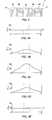
- FIG. 2schematically illustrates the even heating provided by a current flux between the large, cooled, flat electrode surfaces of the system of FIG. 1 .
- FIGS. 2A-2Fschematically illustrate structures and methods for selectively energizing the electrode surface segments of the large, flat electrode arrays of the system of FIG. 1 to tailor the current flux throughout a target zone.
- FIGS. 2G and Hillustrate a probe structure in which an insulator is disposed between the electrodes to prevent edge induced current flux concentration, thereby enhancing the probe's ability to direct a current flux deep into tissues without inducing collateral damage at the engaged tissue surface.
- FIGS. 3-3Egraphically illustrate a method for heating a target tissue between cooled electrodes, wherein the electrode surfaces cool the tissue before, during, and after radiofrequency energy is applied.
- FIG. 4is a cut-away view illustrating pelvic support structures which can be targeted for non-invasive selective contraction using the methods of the present invention.
- FIGS. 4A-4Cillustrate contraction and reinforcing of the pelvic support tissues of FIG. 4 as a therapies for female urinary incontinence.
- FIG. 5is a perspective view of a system for treating female urinary incontinence by selectively shrinking the endopelvic fascia, according to the principles of the present invention.
- FIG. 6is a cross-sectional view illustrating a method for using the system of FIG. 5 to treat female urinary incontinence.
- FIG. 7illustrates an alternative bladder electrode structure for use in the method of FIG. 6 .
- FIGS. 8A and 8Billustrate an alternative vaginal probe having a balloon deployable electrode for use in the method of FIG. 6 .
- FIG. 9is a cross-sectional view illustrating a structure and a method for ultrasonically positioning a temperature sensor within a target tissue.
- FIG. 10illustrates an alternative system for selectively shrinking fascia through intermediate tissues, according to the principles of the present invention.
- FIG. 11schematically illustrates an alternative method for selectively shrinking endopelvic fascia using a vaginal probe having a cooled electrode array.
- FIG. 12schematically illustrates a cooled bipolar vaginal probe and a method for its use, the method including insulating a surface of the endopelvic fascia opposite the probe to limit the depth of heating.
- FIG. 13schematically illustrates a method for selectively shrinking endopelvic fascia by transmitting microwave or ultrasound energy from a cooled vaginal probe.
- FIG. 14is a cross-sectional view illustrating a method for selectively shrinking endopelvic fascia by grasping and folding the wall of the vagina or colon to facilitate focusing of heating upon the fascia, and to enhance shrinkage of the fascia by decreasing tension in the fascia while the fascia is heated, according to the principles of the present invention.
- FIG. 15is a schematic illustration of a kit including the vaginal probe of FIG. 5, together with instructions for its use to shrink tissues, according to the methods of the present invention.
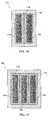
- FIG. 16illustrates an exemplary probe structure having two bipolar cooled electrode surfaces for heating a target tissue through an intervening tissue.
- FIG. 17illustrates an alternative exemplary probe structure similar to the probe of FIG. 16, having three alternating bipolar electrodes.
- FIG. 18is a cross-sectional view through the electrodes of FIG. 16 .
- FIG. 19is a cross-sectional view through the electrodes of FIG. 17 .
- FIGS. 20A-Cillustrate further alternative cooled bipolar probe structures.
- the present inventionoptionally relies on inducing controlled shrinkage or contraction of a support tissue of the body, typically being a collagenous tissue such as fascia, ligament, or the like.
- a support tissue of the bodytypically being a collagenous tissue such as fascia, ligament, or the like.
- the tissue structurewill be one that is responsible in some manner for control of urination, or for supporting a such a tissue.
- Exemplary tissue structuresinclude the urethral wall, the bladder neck, the bladder, the urethra, bladder suspension ligaments, the sphincter, pelvic ligaments, pelvic floor muscles, fascia, and the like.
- Treatment of other conditionsmay be effected by selective shrinking of a wide variety of other tissues, including (but not limited to) the diaphragm, the abdominal wall, the breast supporting ligaments, the fascia and ligaments of the joints, the collagenous tissues of the skin, and the like.
- Related devices, methods, and systemare also described in co-pending U.S. patent application Ser. No. 08/910,370, filed Aug. 13, 1997, the full disclosure of which is incorporated herein by reference.
- Tissue contractionresults from controlled heating of the tissue by affecting the collagen molecules of the tissue. Contraction occurs as a result of heat-induced uncoiling and repositioning of the collagen ⁇ -pleated structure. By maintaining the times and temperatures set forth below, significant tissue contraction can be achieved without substantial collateral tissue necrosis.
- the temperature of the target tissue structurewill generally be raised to a value in the range from about 60° C. to 110° C., often being in the range from about 60° C. to 80° C., and will generally effect a shrinkage of the target tissue in at least one dimension of between about 20 and 50 percent.
- heating energywill be applied for a period of from 30 seconds to 5 minutes. These heating times will vary with separation between the parallel plate electrodes, with a heat time of about 5 minutes often being appropriate for an electrode separation of about 4 cm. Shorter heat times may be used with smaller electrode separation distances.
- the rise in temperaturemay be quite fast, although there will often be advantages in heating tissues more slowly, as this will allow more heat to be removed from tissues which are not targeted for therapy, thereby minimizing collateral damage. However, if too little heating energy is absorbed by the tissue, blood perfusion will transfer the heat away from the targeted tissue, so that the temperature will not rise sufficiently to effect therapy. Fortunately, fascia and other support tissues often have less blood flow than adjacent tissues and organs; this may help enhance the heating of fascia and minimize necrosis of the surrounding structures.
- the total amount of energy deliveredwill depend in part on which tissue structure is being treated, how much tissue is disposed between the target tissue and the heating element, and the specific temperature and time selected for the protocol.
- the power deliveredwill often be in the range from 10 W to 100 W, usually being about 20 W.
- the temperaturewill usually not drop instantaneously when the heating energy stops, so that the tissue may remain at or near the therapy temperature for a time from about 10 seconds to about 2 minutes, and will often cool gradually back to body temperature.
- FIG. 1schematically illustrates a system 10 for shrinking a fascia F disposed between first and second adjacent tissues T 1 , T 2 .
- System 10includes a pair of electrodes 12 , 14 having large, substantially planar tissue engaging surfaces. Electrodes 12 , 14 are aligned substantially parallel to each other with the fascia (and adjacent tissues) disposed therebetween.
- the surfaces of electrodes 12 , 14 which engage the tissueare cooled by a cooling system 16 .
- the cooling systemwill typically include a conduit through the electrode for the circulation of a cooling fluid, but may optionally rely on thermoelectric cooling or the like.
- the temperature of the electrode surfacemay be regulated by varying the temperature or flow rate of the cooling fluid. Cooling may be provided through the use of an ice bath, by endothermic chemical reactions, by standard surgical room refrigeration mechanisms, or the like.
- the cooling systemcools an area which extends beyond the energized electrode surfaces to prevent any hot spots adjacent the tissue surface, and to maximize the heat removal from the tissue without having to resort to freezing the tissue.
- Each of the electrodesis separated into a plurality of electrode segments.
- the electrodeincludes electrode segments 12 a , 12 b , 12 c , 12 d , and 12 e , each of which is electrically isolated from the others. This allows the electrode segments to be individually energized.
- Electrodes 12 , 14are energized by a radiofrequency (RF) power source 18 .
- Multiplexers 20individually energize each electrode segment, typically varying the power or time each segment is energized to more nearly uniformly heat fascia F.
- a controller 22will typically include a computer program which directs the application of cooling flow and RF power through electrodes 12 , 14 , ideally based at least in part on a temperature signal sensed by a temperature sensor 24 .
- Temperature sensor 24may sense the temperature of the tissue at the tissue/electrode interface, or may alternatively sense the temperature of the fascia itself.
- RF poweris applied uniformly across parallel plate electrodes 12 , 14 to produce a current through tissue T.
- a current flux 26is substantially uniform throughout that portion of the tissue which is disposed between the electrode surfaces.
- the flow of electrical current through the electrical resistance of the tissuecauses the temperature of the tissue through which the current passes to rise.
- relatively low radiofrequency currentpreferably in the range from 100 kHz to 1 MHz, helps to avoid collateral damage to nerve and muscle tissues.
- fascia and other collagenated tissueswhich are heated to a temperature range of between about 60° C. and 110° C., and preferably between about 60° C. and 80° C., will contract.
- unstressed fasciawill shrink between about 30% and 50% when heated for a very short time, preferably from between about 0.5 seconds to 5 seconds.
- Such heatingcan easily be provided by conduction of RF currents through the tissue.
- the uniform current flux provided by the large plate electrodes of the present inventionwill produce a substantially uniform heating of the tissue which passes that current.
- the electrode surfacesare cooled. This cooling maintains a cooled tissue region 28 adjacent each electrode below a maximum safe tissue temperature, typically being below about 45° C. Even though heat generation throughout the gap between the electrodes is uniform, the temperature profile of the tissue between the electrodes can be controlled by removing heat through the electrode surfaces during heating.
- sufficient heatingcan be provided by a current of between about 0.2 and 2.0 amps, ideally about 1.0 amp, and a maximum voltage of between about and 100 volts rms1, ideally being about 60 volts rms.
- the electrodeswill often have a surface area of between about 5.0 and 200 cm 2 , and the current density in the target tissue will often be between about 1 mA/cm 2 and 10 mA/cm 2 . This will provide a maximum power in the range from about 10 W to about 100 W, often being about 20 watts. Using such low power settings, if either electrode is lifted away from the engaged tissue, there will be no arcing. Instead, the current will simply stop. This highlights the difference between the electrical tissue heating of the present invention and known electrocautery techniques.
- the ideal geometry to provide a true one-dimensional temperature distributionwould include large parallel plate electrodes having relatively minimal spacing therebetween.
- the present inventioncan also make use of electrode geometries which vary somewhat from this ideal, particularly through the use of array electrodes.
- the use of a single array electrode, in combination with a much larger, uncooled electrode padmay heat tissues disposed near the array, as will be described hereinbelow. Nonetheless, uniform heating is generally enhanced by providing electrode structures having tissue engaging surfaces which are as flat and/or as parallel as practical.
- the parallel electrode surfaceswill be separated by between about 1 ⁇ 3 and 1.0 times the width of the electrode surfaces (or of the smaller surface, if they are different).
- FIG. 2Aschematically illustrates the shape of a target zone which is heated by selectively energizing only electrode segments 12 c and 14 c of cooled electrodes 12 and 14 .
- the temperature of target zone 32(here illustrated schematically with isotemperature contour lines 30 ) is the result of uniform heating between the energized electrode segments, in combination with cooling of tissue T by the electrode surfaces.
- electrode segments 12 a , 12 b , 12 c . . . , and 14 a , 14 b , 14 c . . .can be energized, thereby heating an entire target zone 32 extending throughout tissue T between the electrodes.
- array electrodesprovides still further flexibility regarding the selective targeting of tissues between electrodes 12 and 14 .
- selectively energizing a relatively large effective electrode surface by driving electrodes segments 12 a , 12 b , 12 c , 12 d , and 12 eresults in a low current flux which is widely disbursed throughout the tissue T engaged by electrode 12 .
- By driving this same current through a relatively small effective electrode surface using only a single electrode surface segment 14 cproduces an offset target zone 34 which is much closer to electrode 14 than to electrode 12 .
- varying amounts of electrical currentcan be provided to the electrode segments.
- a fairly uniform target zone 32may be heated between angled electrodes by driving more current through relatively widely spaced electrode segments 12 a , 14 a , and driving less current through more tightly spaced electrode segments 12 e , 14 e , as illustrated in FIG. 2 D.
- these selective targeting mechanismsmay be combined to target fascia and other tissues which are near one slanted electrode, or to selectively target only a portion of the tissues disposed between relatively large electrode arrays.
- Electrode 12here comprises three electrode surface segments 12 a , 12 b , and 12 c separated by insulating spaces 21 .
- a plastic housing 23defines a flow path between a cooling inflow port 25 and a cooling outflow port 27 , while heat transfer between the cooling fluid and the electrode surface is enhanced by a thermally conductive front plate 29 .
- Front plate 29generally comprises a thermally conductive metal such as aluminum.
- Electrode surface segments 12 a , 12 b , and 12 cmay comprise surfaces of separated segments 31 of aluminum foil. Segments 31 may be electrically isolated by a mylar insulation sheet 33 disposed between the segments and front plate 29 .
- the array electrode structures of the present inventionwill generally include a series of conductive surface segments which are aligned to define a substantially flat electrode surface.
- the electrode surface segmentsare separated by an electrically insulating material, with the insulation being much smaller in surface area than the conductive segments.
- the peripheral edges of the electrode segmentsmay be rounded and/or covered by an insulating material to prevent concentrations of the electrical potential and injury to the engaged tissue surfaces.
- the present inventionalso encompasses electrodes which are segmented into two-dimensional arrays. Where opposed sides of the tissue are accessible for relatively large array structures, such as along the exposed skin, or near the major cavities and orifices of the body, the electrode surfaces will preferably be separated by a gap which is less than a width (and length) of the electrodes.
- one electrode structuremay be disposed within a large body cavity such as the rectum or vagina, while the other is placed in an adjacent cavity, or on the skin so that the region to be treated is between the electrode surfaces.
- one or both electrodesmay be inserted and positioned laparoscopically. It will often be desirable to clamp the tissue tightly between the electrodes to minimize the gap therebetween, and to promote efficient coupling of the electrode to the tissue.
- an alternative cooled electrode structurefor use with any of the methods, devices, and systems described herein makes use of an insulator between electrodes and/or electrode segments to minimize edge induced current concentration.
- an insulating rib or film between electrodesBy positioning an insulating rib or film between electrodes, the RF current can be directed over the insulator without having to resort to widely spaced electrodes or electrode segments, large radiused edges, and the like.
- an insulating rib 39 ais positioned roughly perpendicular to, and disposed between, the two plate electrodes. Electrical current very near the surface of an insulator will generally flow parallel to the insulator surface. In contrast, current which is very near a conductor will generally flow perpendicular to the conductor surface. In the absence of rib 39 a , the current density is greatest directly between the two electrodes at their adjacent edges, and will tend to cause a bum at that location.
- rib 39 aBy providing vertical rib 39 a between the electrode surfaces, the current can be directed away from the electrodes and over the protruding rib. As a result, the rib will tend to induce a region of approximately parallel current flow beyond the end of the protruding rib and roughly perpendicular to the electrode surfaces.
- rib 39 adirects the greatest current density deep into the tissue, allowing a bi-polar current between the electrodes to heat and shrink fascia F without inducing a burn at the surface of intermediate tissue T.
- rib 39 amay distend the engaged tissue surface.
- a sharpened ribmay incise the tissue to direct the heating current flux deeper through the intermediate tissue and into an inaccessible target tissue.
- the insulatormay comprise a film 39 b as illustrated in FIG. 2 H.
- Film 39 bis disposed between electrodes 35 , 37 , and extends over the adjacent edges of the electrodes to avoid edge induced concentration of current flux at this location.
- FIG. 3illustrates three distinct regions of tissue T disposed between electrodes 12 and 14 .
- Target zone 32will typically comprise fascia or some other collagenated tissue, while the surfaces of the electrodes engage an intermediate tissue 36 disposed on either side of the fascia.
- target zone 32will typically be heated to a temperature above about 60° C.
- This stunned tissue 38will typically be heated in the range from about 45° C. to about 60° C., and may therefore undergo some limited injury during the treatment process. As a result, it is generally desirable to minimize the time this tissue is at an elevated temperature, as well as the amount of stunned tissue.
- the temperature profile of tissue T along an axis X between electrodes 12 and 14is substantially uniform at body temperature.
- the tissuewill preferably be pre-cooled by the surfaces of electrodes 12 , 14 , generally using an electrode surface temperature of at or above 0° C.
- Pre-coolingwill substantially decrease the temperature of intermediate tissues 36 , and will preferably at least partially decrease the temperature of stunned tissue 38 .
- At least a portion of the target zoneremains at or near the initial body temperature, as illustrated in FIG. 3 B.
- Pre-cooling timewill often depend on electrode separation and tissue heat diffusity.
- the RF currentis directed through the tissue between the electrodes to heat the tissue.
- a temperature sensorcan be placed at the center of target zone 32 to help determine when the pre-cooling has been applied for the proper time to initiate RF heating.
- the current fluxapplies a fairly uniform heating throughout the tissue between the electrodes, and the electrode surfaces are often cooled throughout the heating process.
- target zone 32has the highest temperature upon initiation of the heating cycle, and as the target zone is farthest from the cooled electrodes, a relatively small amount of heat flows from the target zone into the electrodes, and the target zone is heated to a significantly higher temperature than intermediate tissue 36 .
- Heatis applied until the target zone is at or above a treatment temperature, typically resulting in a temperature distribution such as that illustrated in FIG. 3 C.
- a treatment temperaturetypically resulting in a temperature distribution such as that illustrated in FIG. 3 C.
- the cooling systemcontinues to circulate cold fluid through the electrode, and to remove heat from the tissue, after the heating radiofrequency energy is halted.
- substantially the entire tissueis below the maximum safe tissue temperature (as in FIG. 3 D)
- coolingcan be halted, and the tissue can be allowed to return to standard body temperature, as illustrated in FIG. 3 E.
- RF currentmay be driven between the two cooled plate electrodes using intermittent pulses of excitation.
- intermittent or pulsed excitationencompasses cyclically increasing and decreasing delivered power, including cyclical variations in RMS power provided by amplitude modulation, waveform shape modulation, pulse width modulation, or the like. Such intermittent excitation will preferably provide no more than about 25% of the RMS power of the pulses during the intervals between pulses.
- the electrodeswill be energized for between about 10 and 50% of a total heating session.
- electrodes 12 and 14may be energized for 15 secs. and then turned off for 15 secs. and then cycled on and off again repeatedly until the target tissue has been heated sufficiently to effect the desired shrinkage.
- the electrode surfaces (and the surrounding probe structure which engages the tissue)will be cooled throughout the on/off cycles of the heating sessions.
- the therapeutic heating and cooling provided by the electrodes of the present inventionwill often be verified and/or controlled by sensing the temperature of the target tissue and the adjacent tissue directly.
- temperature sensingmay be provided using a needle containing two temperature sensors: one at the tip to be positioned at the center of the treatment zone, and the second along the shaft of the needle so as to be positioned at the edge of the desired protection zone.
- the second sensorwill be placed along the border between the intermediate tissue and the target tissue, typically somewhere along stunned tissue 38 .
- the temperature sensorswill preferably sense the tissue temperature during the intervals between pulses to minimize errors induced by the heating RF current flux in the surrounding tissue.
- the temperature sensorsmay comprise thermistors, thermocouples, or the like.
- the temperature sensing needlemay be affixed to or advanceable from a probe supporting the electrode adjacent to or between the electrode segments. Alternatively, two or more needles may be used.
- controller 22will provide signals to cooling system 16 and the electrodes so that the electrodes chill the engaged tissue continually while the RF current is pulsed to increase the temperature of the treatment zone incrementally, ideally in a step-wise manner, until it reaches a temperature of 60° C. or more, while at the same time limiting heating of the intermediate tissue to 45° C. or less per the feedback from the needles.
- pre-chilling time, the duration of the heat, the lengths of the heating intervals (and the time between heating intervals) during intermittent heating, and the radiofrequency heating currentmay be controlled without having direct feedback by using dosimetry. Where the thermal properties of these tissues are sufficiently predictable, the effect of treatment can be estimated from previous measurements.
- endopelvic fascia EFdefines a hammock-like structure which extends between the arcus tendineus fascia pelvis ATFP. These latter structures extend between the anterior and posterior portions of the pelvic bone, so that the endopelvic fascia EF largely defines the pelvic floor.
- the bladderIn women with urinary stress incontinence due to bladder neck hypermobility, the bladder has typically dropped between about 1.0 cm and 1.5 cm (or more) below its nominal position. This condition is typically due to weakening of the pelvic support structures, including the endopelvic fascia, the arcus tendineus fascia pelvis, and the surrounding ligaments and muscles, often as the result of bearing children.
- the present inventiongenerally provides a therapy which applies gentle heating to shrink the length of the support tissues and return bladder B to its nominal position.
- the bladderis still supported by the fascia, muscles, ligaments, and tendons of the body.
- the endopelvic fascia EF and arcus tendineus fascia pelvis ATFPare controllably contracted to shrink them and re-elevate the bladder toward its original position.
- bladder Bcan be seen to have dropped from its nominal position (shown in phantom by outline 36 ). While endopelvic fascia EF still supports bladder B to maintain continence when the patient is at rest, a momentary pressure pulse P opens the bladder neck N, resulting in a release through urethra UR.
- a known treatment for urinary stress incontinencerelies on sutures S to hold bladder neck N closed so as to prevent inadvertent voiding, as seen in FIG. 4 B.
- Sutures Smay be attached to bone anchors affixed to the pubic bone, ligaments higher in the pelvic region, or the like. In any case, loose sutures provide insufficient support of the bladder neck N and fail to overcome urinary stress incontinence, while overtightening of sutures S may make normal urination difficult and/or impossible.
- bladder Bcan be elevated from its lowered position (shown by lowered outline 38 ).
- a pressure pulse Pis resisted in part by endopelvic fascia EF, which supports the lower portion of the bladder and helps maintain the bladder neck in a closed configuration.
- fine tuning of the support provided by the endopelvic fasciais possible through selective contraction of the anterior portion of the endopelvic fascia to close the bladder neck and raise bladder B upward.
- lateral repositioning of bladder B to a more forward positionmay be affected by selectively contracting the dorsal portion of endopelvic fascia EF.
- the therapy of the present inventionmay be tailored to the particular elongation exhibited by a patient's pelvic support tissues.
- fasciamay effectively treat cystocele, hiatal, and inguinal hernias, and may even be used in cosmetic procedures such as abdominoplasty (through selectively shrinking of the abdominal wall), to remove wrinkles by shrinking the collagenated skin tissues, or to lift sagging breasts by shrinking their support ligaments.
- System 40includes a vaginal probe 42 and a bladder probe 44 .
- Vaginal probe 42has a proximal end 46 and a distal end 48 .
- Electrode 12(including segments 12 a , 12 b , 12 c , and 12 d ) is mounted near the distal end of the probe.
- Vaginal probe 42will typically have a diameter of between about 2 and 4 cm, and will often have a shaft length of between about 6 and 12 cm.
- An electrical coupling 50is coupleable to an RF power supply, and optionally to an external control processor. Alternatively, a controller may be integrated into the probe itself.
- a fluid coupling 52provides attachment to a cooling fluid system. Cooling fluid may be recycled through the probe, so that more than one fluid couplers may be provided.
- the segments of electrode 12are quite close to each other, and preferably define a substantially flat electrode surface 54 .
- the cooling fluidflows immediately below this surface, the surface material preferably being both thermally and electrically conductive.
- surface 54is as large as the tissue region to be treated, and a thermocouple or other temperature sensor may be mounted adjacent the surface for engaging the tissue surface and measuring the temperature of the engaged tissue.
- Urethral probe 44includes a balloon 56 supporting a deployable electrode surface. This allows the use of a larger electrode surface than could normally be inserted through the urethra, by expanding the balloon structure within the bladder as illustrated in FIG. 6 .
- a narrower cylindrical electrodemight be used which engages the surrounding urethra, the urethral electrode optionally being separated into more than one segment along the length and/or around the circumference of the probe shaft. Radiofrequency current will divert from such a tightly curved surface and heat the nearby tissue. The electrode can again be chilled to protect the urethral lining from thermal damage.
- the endopelvic fasciawill preferably be disposed between the electrodes of the urethral probe 44 and vaginal probe 42 when the vaginal probe is levered to the right or left side of the pelvis by the physician.
- Balloon 56 of urethral probe 44is here illustrated in its expanded configuration, thereby maximizing a surface area of electrode 14 , and also minimizing its curvature (or, in other words, maximizing the radius of curvature of the electrode surface).
- cooled fluid recirculating through balloon 56will cool electrode 14 , so that cooled electrodes 12 , 14 will selectively heat the endopelvic fascia EF without damaging the delicate vaginal mucosa VM or the bladder wall.
- Urethral probe 44 and vaginal probe 42may optionally be coupleable to each other to facilitate aligning the probes on either side of the target tissue, either mechanically or by some remote sensing system.
- one of the probesmay include an ultrasound transducer, thereby facilitating alignment of the electrode surfaces and identification of the target tissue.
- the proximal ends of the probesmay attach together to align the electrodes and/or clamp the target tissue between the probes.
- a mesh electrode 58may be unfurled within the bladder in place of urethral probe 44 .
- Mesh electrode 58preferably comprises a highly flexible conductive element, optionally being formed of a shape memory alloy such as NitinolTM.
- the bladdermay be filled with an electrically non-conductive fluid such as distilled water during the therapy, so that little or no RF current would flow into the bladder wall beyond the contact region between the electrode and the bladder.
- an upper portion 58 of the mesh structuremay be masked off electrically from the energized mesh surface of the lower portion.
- FIGS. 8A and 8Billustrate an optional deployable electrode support structure for use with vaginal probe 42 .
- Electrode 12can be collapsed into a narrow configuration for insertion and positioning within the vaginal cavity, as illustrated in FIG. 8 A. Once electrode 12 is positioned adjacent to the target tissue, electrode 12 can be expanded by inflating lateral balloon 60 so that the deployed electrode assumes a substantially planar configuration. A cooling fluid may be recirculated through lateral balloon 60 to cool the electrode 12 , and a thermally insulating layer 62 can help to minimize heat transfer from the adjacent tissues.
- the tissue shrinking system of the present inventionmay also include an ultrasonic transducer 64 for positioning one or both electrodes relative to fascia F.
- Transducer 64will preferably include a transducer material such as PVDF (polyvinyladine fluoride) or PZT-5A (lead zirconate titanate).
- Transducer 64may be incorporated into the probes of the present invention, thereby allowing the relative positions and angle between the electrode surfaces to be measured directly.
- transducer 64may be positioned adjacent to fascia F, and a mark may be drawn upon the exposed skin (or other tissue surface) adjacent the fascia for subsequent positioning of a probe.
- Transducer 64optionally includes a needle guide 66 for insertion of a biopsy needle 68 through the view of the transducer and into the fascia. A thermocouple or other temperature sensing element may then be deployed in place of the biopsy needle.
- an alternative tissue shrinking system 70includes an electrode 12 mounted on a speculum 72 .
- Speculum 72may be used to manually position electrode 12 within the vagina (or another body orifice), while an external applicator 74 is positioned against the skin to clamp the target tissue between electrode 14 and electrode 12 .
- the speculum and external applicator 74may be manually manipulated to clamp the target tissue between these structures, while electrical leads 76 and cooling fluid conduits 78 couple the probe and applicator to the remaining system components.
- FIG. 11schematically illustrates a single probe heating system 80 which takes advantage of this mechanism to selectively heat fascia near a single probe.
- offset target zone 34is heated by RF energy selectively directed through the segments of electrode 12 .
- the vaginal mucosa VM disposed between vaginal probe 42 and endopelvic fascia EFis protected by cooling the surface of electrode 12 , as described above.
- Bladder B (and the other tissues opposite endopelvic fascia EF relative to vaginal probe 42 )are heated significantly less than endopelvic fascia EF due to the divergence of the current as it travels away from electrode 12 and towards electrode pad 82 , which may optionally be disposed on the abdomen, back, or thigh.
- cooling watermay be circulated through bladder B to further protect these tissues.
- Multiplexer 20selectively energizes the electrode segments for differing amounts of time and/or with differing power to help tailor the temperature profile of offset target zone 34 about endopelvic fascia EF for selective uniform heating with minimal collateral damage.
- Various treatment regimes with alternating heating and cooling cyclescan help to focus the heat therapy on the desired tissues.
- Multiplexer 20may be disposed outside of the body in a proximal housing, in a separate control unit housing, or the like.
- the multiplexercan provide electrode segment drive control, optionally with switches for each electrode segment.
- a cooled bipolar probe 84includes many of the structures and features described above, but here includes a series of bipolar electrodes 86 .
- Bipolar electrodes 86will preferably be cooled, and cooling surfaces may also be disposed between the separated electrodes.
- bipolar electrodes 86may optionally be formed as parallel cylindrical structures separated by a predetermined spacing to help direct a bipolar current flux 88 through tissue which lies within a particular treatment distance of probe 84 .
- the depth of penetration of the bipolar energyis controlled by the spacing and size of the electrode structures.
- the tissues distant from the cooled electrodeswill be heated to a lesser extent than the tissues directly engaged by the electrodes, but will also be cooled to a lesser extent by the cooled electrodes and other cooling surfaces of bipolar probe 84 .
- the tissues close to the electrodeswill be heated to a greater extent, and will also be cooled more effectively. Therefore, a controlled regimen of timed pre-cooling and then heating is used to selectively raise the temperature of endopelvic fascia EF (or any other target tissue), while the vaginal mucosa adjacent probe 84 is protected by the cooled probe. Tissues at depths greater than the endopelvic fascia will generally be protected by the dissipation of bipolar current 88 .
- Insulating fluid 90may optionally comprise a gas such as CO 2 , or may alternatively comprise a liquid such as isotonic DextranTM in water. Insulating fluid 90 will electrically insulate the adjacent organs and prevent heating of tissues that might otherwise be in contact with the vaginal fascial outer lining. Insulating fluid 90 is here injected using a small needle incorporated into bipolar probe 84 , the needle preferably being 22 ga or smaller.
- microwave probe 94includes microwave antennas 96 which direct microwave heating energy 98 through the vaginal mucosa VM and onto endopelvic fascia EF.
- Microwave probe 94will again typically include a cooled probe surface to minimize damage to vaginal mucosa VM.
- the microwavemay optionally be produced by a phased array microwave antenna to decrease heating next to the cold probe relative to the heating of endopelvic fascia EF, or a more conventional microwave antenna may be used.
- Microwave power having a frequency of about 2250 MHzis most often used for heating.
- the use of extremely high frequency microwaveswould permit constructive interference at the intersection of microwave energy streams by control of the microwave frequency, phase, and electrode spacing.
- Such constructive interference of microwavesmay be used to enhance the heating of the target tissue relative to the heat produced in the intermediate tissue between microwave probe 94 and endopelvic fascia EF (in this example).
- Injection of an electrically insulating fluid, such as DextranTMmay be used to absorb microwave energy and protect tissues beyond the target zone.
- injection of a liquid contrast mediummight be used to enhance visualization of the treatment region, increasing the visibility and clarity of the vagina V, bladder B, the other adjacent organs, and the spaces therebetween.
- Such a contrast mediumwill typically be highly visible under ultrasonic or fluoroscopic imaging modalities.
- An alternative form of energy which may be used in a probe schematically similar to that illustrated in FIG. 13is ultrasonic heating.
- a cooled ultrasonic probecould be used to provide heating of the endopelvic fascia adjacent the vagina, preferably while protecting the adjacent tissues using a material which reflects ultrasound. Suitable protection materials include CO 2 or a liquid/foam emulsion material.
- High intensity ultrasoundis able to heat tissues at a distance from the probe, and may be focused to apply the most intense heating at a particular treatment site. Concentration of ultrasound energy deep in the body may avoid heating of tissues at the entry site of the focused ultrasound beam, although gas pockets and bony structures may absorb and/or reflect the focused ultrasound energy, so that tissues may be damaged by both localized heating and cavitation.
- the surface of an ultrasound probewill typically be cooled to protect the tissues which are directly engaged by the probe.
- FIG. 14A cross-section of a grasping bipolar probe 100 is illustrated in FIG. 14 .
- Grasping probe 100grips and folds an anterior portion of the vaginal wall, including both the vaginal mucosa VM and endopelvic fascia EF, as shown.
- the targeted fasciamay be separated from the probe by muscle, vasculature, and the like, as well as by vaginal mucosa VM.
- Endopelvic fascia EFis typically about 1 mm thick, while the grasped, folded vaginal wall will typically be between about 10 mm to 14 mm thick. The folded endopelvic fascia EF may thus be heated and contracted between cooled bipolar electrodes 102 , as described above.
- cooled bipolar electrodes 102may optionally be formed as wide elongate plates. Grasping may be accomplished mechanically or by applying a vacuum to draw the vaginal wall into a cavity 104 of grasping probe 100 . By drawing the endopelvic fascia into close proximity of both electrodes, a finer focusing of the heating may be accomplished, thereby minimizing the damage to adjacent tissues. Additionally, grasping probe 100 may draw the tissue inward to relieve any tension in the fascia, thereby enhance the shrinkage. As described above regarding FIG. 12, CO 2 or some other insulating medium may be used for additional protection of adjacent tissues and organs.
- a kit 110includes vaginal probe 42 and instructions 112 for use of the probe to shrink tissues, the probe and instructions disposed in packaging 114 .
- the instructionsmay set forth the method steps for using probe 42 described hereinabove for selectively shrinking pelvic support tissues as a therapy for urinary incontinence, or may alternatively recite any of the other described methods. Additional elements for system 10 (see FIG. 1) may also be included in kit 110 , or may be packaged separately.
- Instructions 112will often comprise printed material, and may be found in whole or in part on packaging 114 .
- instructions 112may be in the form of a recording disk or other computer-readable data, a video tape, a sound recording, or the like.
- the present inventionfurther encompasses methods for teaching the above-described methods by demonstrating the methods of the present invention on patients, animals, physical or computer models, and the like.
- Exemplary cooled bipolar electrode structures having a protruding filmare illustrated in more detail in FIGS. 16-19.
- a two electrode probe 110is illustrated in a front view in FIG. 16 .
- Two electrode probehas a probe body 112 supporting a first electrode 114 and a second electrode 116 .
- An electrically insulating and thermally conducting film 118extends along the electrode surfaces, covering the adjacent edges of the electrodes so as to prevent localized heating and charring of tissues when the electrodes are energized in a bipolar manner.
- Electrodes 114 , 116can be seen in more detail in the cross-section of FIG. 18 .
- the electrodescomprise electrically and thermally conductive materials, typically being formed as metal tubes, and ideally comprising stainless steel, brass, copper, steel, titanium, gold, or the like.
- the exposed electrode surfaces of the electrode tubesmay be coated with a thin film comprising a biocompatible material such as silver, or any of the other suitable materials listed above.
- Electrodes 114 , 116have electrode surface 120 and side surfaces 122 with an edge 124 therebetween.
- a cooling fluid 126is disposed within the lumen of the electrode tubes, and may flow through the tubes either in series or in parallel, with the cooling fluid flow path optionally extending through probe body 1 12 , and/or directly between the electrode tubes.
- Typical cooling fluidsmay comprise electrically conductive fluids such as chilled, physiological saline in separate fluid paths for the bipolar electrode pairs, but will preferably comprise a poor electrical conductor such as water and/or isotonic DextranTM solution.
- the cooling fluidwill typically be close to, but often above 0° C.
- Film 118will preferably be electrically insulating and thermally conducting so as to provide cooling along the exposed film surface between first and second electrodes 114 , 116 .
- Film 118may comprise a variety of materials, such as KaptonTM tape, MylarTM tape, a PTFE tape such as TeflonTM, and anodization. Film 118 may be applied as a tape, a fluid (such as a paint or an adhesive), a plating, or the like, and will generally have sufficient thickness to act as an electrical insulator and a thermal conductor. Further alternative insulation film materials may comprise polyimide, spray-on ceramics, electroplated insulation, photoimageable polymers, epoxy, and urethanes.
- the exposed electrode surfaces 120have a width in a range from about 3 mm to 10 mm, while the exposed cooling surface of film 118 disposed between the electrodes also has a width in a range from about 3 mm to about 10 mm.
- the electrodeneed not be limited to a one or two dimensional array. In fact, electrode widths and separation may be easily varied along the axes of the tubes by applying film 118 over a curving area.
- a three electrode probe 130includes three tubular electrodes 132 , 134 , 136 mounted in a plastic probe body 112 , with electrodes and film structures substantially similar to those of FIGS. 16 and 18.
- electrode surfaces 120need not be completely planer.
- the exposed electrode surfacesmay comprise portions of a large diameter cylinder as illustrated in co-pending PCT Application No. PCT/US98/16754, filed on Oct. 7, 1998, the full disclosure of which is incorporated herein by reference, or may comprise portions of a sphere.
- theymay be energized either simultaneously or sequentially as bipolar pairs.
- a wide variety of electrode geometries and treatment cyclesmight be used.
- FIGS. 20A-CStill further related cooled probe structures are illustrated in FIGS. 20A-C.
- film 118isolates cooling fluid path tubes 140 electrically, and allows contiguous cooling across separated bipolar electrodes. This and other probe structures having three or more electrodes will often be multiplexed by driving bipolar current between, for example, electrodes 132 and 134 , and then between electrodes 134 and 136 .
- Cooling tubes 140are electrically insulated, and can be allowed to float with respect to electrodes 132 , 134 , and 136 .
- the width of the insulation provided by film 118 between the exposed electrodesis related to the maximum treatment depth.
- both the width of the active exposed electrodes and the width of the electrically insulated separation distance between the electrodesdetermine the maximum depth of the intervening tissue which can be thermally cooled and effectively protected while treating the target tissue.
- Third, reducing the separation gap between electrodeswill eventually result in localized hot spots at the surface of the inside edges of the powered electrodes. The minimum interelectrode separation can be decreased by multiplexing or alternating the bipolar power between three or more electrodes as described above.
- An electrically insulating filmextends to, and preferably over and beyond the electrode edge, and/or a protruding insulating rib may also reduce localized hot spots.
- FIGS. 20B and CStill further alternative electrode tube/film structures are illustrated in FIGS. 20B and C.
- the embodiment of FIG. 20Cincludes electrode tubes which define acute angles between the electrode and side surfaces.
- Film 118here acts as a living hinge between the electrodes, allowing the probe to conform to a curving tissue surface such as a lumenal wall.
- the acute tube anglesincrease the range of flexibility of the probe, and similar probes may be used having cooling tubes between active electrodes, a combination of different electrode tube shapes, or the like.
Landscapes
- Health & Medical Sciences (AREA)
- Surgery (AREA)
- Engineering & Computer Science (AREA)
- Life Sciences & Earth Sciences (AREA)
- Biomedical Technology (AREA)
- Molecular Biology (AREA)
- Nuclear Medicine, Radiotherapy & Molecular Imaging (AREA)
- Plasma & Fusion (AREA)
- Physics & Mathematics (AREA)
- Heart & Thoracic Surgery (AREA)
- Medical Informatics (AREA)
- Otolaryngology (AREA)
- Animal Behavior & Ethology (AREA)
- General Health & Medical Sciences (AREA)
- Public Health (AREA)
- Veterinary Medicine (AREA)
- Surgical Instruments (AREA)
- Thermotherapy And Cooling Therapy Devices (AREA)
Abstract
Description
Claims (15)
Priority Applications (2)
| Application Number | Priority Date | Filing Date | Title |
|---|---|---|---|
| US09/925,501US6533780B1 (en) | 1997-08-13 | 2000-10-23 | Ribbed electrodes and methods for their use |
| US10/351,245US7004942B2 (en) | 1998-01-14 | 2003-01-23 | Ribbed electrodes and methods for their use |
Applications Claiming Priority (7)
| Application Number | Priority Date | Filing Date | Title |
|---|---|---|---|
| US08/910,369US6035238A (en) | 1997-08-13 | 1997-08-13 | Noninvasive devices, methods, and systems for shrinking of tissues |
| US08/910,775US6480746B1 (en) | 1997-08-13 | 1997-08-13 | Noninvasive devices, methods, and systems for shrinking of tissues |
| US08/910,371US6081749A (en) | 1997-08-13 | 1997-08-13 | Noninvasive devices, methods, and systems for shrinking of tissues |
| US7132498P | 1998-01-14 | 1998-01-14 | |
| US09/133,496US6216704B1 (en) | 1997-08-13 | 1998-08-12 | Noninvasive devices, methods, and systems for shrinking of tissues |
| US09/229,508US6283987B1 (en) | 1998-01-14 | 1999-01-12 | Ribbed electrodes and methods for their use |
| US09/925,501US6533780B1 (en) | 1997-08-13 | 2000-10-23 | Ribbed electrodes and methods for their use |
Related Parent Applications (1)
| Application Number | Title | Priority Date | Filing Date |
|---|---|---|---|
| US09/229,508ContinuationUS6283987B1 (en) | 1997-08-13 | 1999-01-12 | Ribbed electrodes and methods for their use |
Related Child Applications (1)
| Application Number | Title | Priority Date | Filing Date |
|---|---|---|---|
| US10/351,245ContinuationUS7004942B2 (en) | 1998-01-14 | 2003-01-23 | Ribbed electrodes and methods for their use |
Publications (1)
| Publication Number | Publication Date |
|---|---|
| US6533780B1true US6533780B1 (en) | 2003-03-18 |
Family
ID=22100613
Family Applications (3)
| Application Number | Title | Priority Date | Filing Date |
|---|---|---|---|
| US09/229,508Expired - LifetimeUS6283987B1 (en) | 1997-08-13 | 1999-01-12 | Ribbed electrodes and methods for their use |
| US09/925,501Expired - LifetimeUS6533780B1 (en) | 1997-08-13 | 2000-10-23 | Ribbed electrodes and methods for their use |
| US10/351,245Expired - LifetimeUS7004942B2 (en) | 1998-01-14 | 2003-01-23 | Ribbed electrodes and methods for their use |
Family Applications Before (1)
| Application Number | Title | Priority Date | Filing Date |
|---|---|---|---|
| US09/229,508Expired - LifetimeUS6283987B1 (en) | 1997-08-13 | 1999-01-12 | Ribbed electrodes and methods for their use |
Family Applications After (1)
| Application Number | Title | Priority Date | Filing Date |
|---|---|---|---|
| US10/351,245Expired - LifetimeUS7004942B2 (en) | 1998-01-14 | 2003-01-23 | Ribbed electrodes and methods for their use |
Country Status (6)
| Country | Link |
|---|---|
| US (3) | US6283987B1 (en) |
| EP (1) | EP1047347B1 (en) |
| AU (1) | AU743478B2 (en) |
| CA (1) | CA2317410A1 (en) |
| DE (1) | DE69941252D1 (en) |
| WO (1) | WO1999035983A1 (en) |
Cited By (41)
| Publication number | Priority date | Publication date | Assignee | Title |
|---|---|---|---|---|
| US20020193786A1 (en)* | 1998-10-23 | 2002-12-19 | Dany Berube | Directional microwave ablation instrument with off-set energy delivery portion |
| US20030135249A1 (en)* | 1998-01-14 | 2003-07-17 | Surx, Incorporated | Ribbed electrodes and methods for their use |
| US20030163128A1 (en)* | 2000-12-29 | 2003-08-28 | Afx, Inc. | Tissue ablation system with a sliding ablating device and method |
| US20040106937A1 (en)* | 2002-06-21 | 2004-06-03 | Afx, Inc. | Clamp accessory and method for an ablation instrument |
| US20040152990A1 (en)* | 2003-01-29 | 2004-08-05 | Mackool Richard J. | Monitoring thermal conditions to vary operation of an ultrasonic needle tip of a surgical instrument |
| US20050171582A1 (en)* | 2004-01-30 | 2005-08-04 | Solarant Medical, Inc. | Electrically heated/phase change probe temperature control |
| US20050171583A1 (en)* | 2004-01-30 | 2005-08-04 | Solarant Medical, Inc. | Heating method for tissue contraction |
| US20050234445A1 (en)* | 2002-03-05 | 2005-10-20 | Baylis Medical Company Inc. | Method of treating biological tissue |
| US7099717B2 (en) | 2002-01-03 | 2006-08-29 | Afx Inc. | Catheter having improved steering |
| US20070027511A1 (en)* | 2005-08-01 | 2007-02-01 | Ty Fairneny | Collagen injection combined with focused ultrasound for the treatment of incontinence |
| US7192427B2 (en) | 2002-02-19 | 2007-03-20 | Afx, Inc. | Apparatus and method for assessing transmurality of a tissue ablation |
| US7226446B1 (en)* | 1999-05-04 | 2007-06-05 | Dinesh Mody | Surgical microwave ablation assembly |
| US20070233191A1 (en)* | 2006-02-07 | 2007-10-04 | Parmer Jonathan B | Vaginal remodeling device and methods |
| US7294127B2 (en) | 2002-03-05 | 2007-11-13 | Baylis Medical Company Inc. | Electrosurgical tissue treatment method |
| US7301131B2 (en) | 2000-01-18 | 2007-11-27 | Afx, Inc. | Microwave ablation instrument with flexible antenna assembly and method |
| US7303560B2 (en) | 2000-12-29 | 2007-12-04 | Afx, Inc. | Method of positioning a medical instrument |
| US20080065062A1 (en)* | 2002-03-05 | 2008-03-13 | Baylis Medical Company Inc. | Electrosurgical tissue treatment method |
| US7346399B2 (en) | 1999-05-28 | 2008-03-18 | Afx, Inc. | Monopole tip for ablation catheter |
| US20080243121A1 (en)* | 2007-04-02 | 2008-10-02 | Tomoyuki Takashino | Curative treatment system, curative treatment device, and treatment method for living tissue using energy |
| US20080243213A1 (en)* | 2007-04-02 | 2008-10-02 | Tomoyuki Takashino | Curative treatment system, curative treatment device, and treatment method for living tissue using energy |
| US20090082703A1 (en)* | 2007-09-26 | 2009-03-26 | Robert Muratore | Method and apparatus for the treatment of tendon abnormalities |
| US20090149930A1 (en)* | 2007-12-07 | 2009-06-11 | Thermage, Inc. | Apparatus and methods for cooling a treatment apparatus configured to non-invasively deliver electromagnetic energy to a patient's tissue |
| US20090163905A1 (en)* | 2007-12-21 | 2009-06-25 | Winkler Matthew J | Ablation device with internally cooled electrodes |
| US20090270954A1 (en)* | 2008-04-28 | 2009-10-29 | Thermage, Inc. | Methods and apparatus for predictively controlling the temperature of a coolant delivered to a treatment device |
| US20090318850A1 (en)* | 2008-06-19 | 2009-12-24 | Thermage, Inc. | Leakage-resistant tissue treatment apparatus and methods of using same |
| US20090318851A1 (en)* | 2008-06-19 | 2009-12-24 | Thermage, Inc. | Leakage-resistant tissue treatment apparatus and methods of using such tissue treatment apparatus |
| WO2010103507A1 (en)* | 2009-03-12 | 2010-09-16 | Syneron Medical Ltd. | An rf electrode for aesthetic and bodyshaping devices and method of using same |
| US20110178584A1 (en)* | 2009-09-18 | 2011-07-21 | Parmer Jonathan B | Vaginal remodeling device and methods |
| US8489192B1 (en) | 2008-02-15 | 2013-07-16 | Holaira, Inc. | System and method for bronchial dilation |
| US8740895B2 (en) | 2009-10-27 | 2014-06-03 | Holaira, Inc. | Delivery devices with coolable energy emitting assemblies |
| US8808280B2 (en) | 2008-05-09 | 2014-08-19 | Holaira, Inc. | Systems, assemblies, and methods for treating a bronchial tree |
| US8882755B2 (en) | 2002-03-05 | 2014-11-11 | Kimberly-Clark Inc. | Electrosurgical device for treatment of tissue |
| US8911439B2 (en) | 2009-11-11 | 2014-12-16 | Holaira, Inc. | Non-invasive and minimally invasive denervation methods and systems for performing the same |
| US8998892B2 (en) | 2007-12-21 | 2015-04-07 | Atricure, Inc. | Ablation device with cooled electrodes and methods of use |
| US9149328B2 (en) | 2009-11-11 | 2015-10-06 | Holaira, Inc. | Systems, apparatuses, and methods for treating tissue and controlling stenosis |
| US9339618B2 (en) | 2003-05-13 | 2016-05-17 | Holaira, Inc. | Method and apparatus for controlling narrowing of at least one airway |
| US9398933B2 (en) | 2012-12-27 | 2016-07-26 | Holaira, Inc. | Methods for improving drug efficacy including a combination of drug administration and nerve modulation |
| US9415235B2 (en) | 2012-03-16 | 2016-08-16 | Viveve, Inc. | Vaginal remodeling device and method |
| US9474573B2 (en) | 2002-03-05 | 2016-10-25 | Avent, Inc. | Electrosurgical tissue treatment device |
| US20220211435A1 (en)* | 2019-04-30 | 2022-07-07 | Creo Medical Limited | Electrosurgical instrument with non-liquid thermal transfer |
| US11511110B2 (en) | 2018-06-27 | 2022-11-29 | Viveve, Inc. | Methods for treating urinary stress incontinence |
Families Citing this family (94)
| Publication number | Priority date | Publication date | Assignee | Title |
|---|---|---|---|---|
| US6024733A (en) | 1995-06-07 | 2000-02-15 | Arthrocare Corporation | System and method for epidermal tissue ablation |
| US7758537B1 (en) | 1995-11-22 | 2010-07-20 | Arthrocare Corporation | Systems and methods for electrosurgical removal of the stratum corneum |
| US6104959A (en) | 1997-07-31 | 2000-08-15 | Microwave Medical Corp. | Method and apparatus for treating subcutaneous histological features |
| JP2001514921A (en)* | 1997-08-13 | 2001-09-18 | サークス, インコーポレイテッド | Non-invasive devices, methods, and systems for tissue contraction |
| US9023031B2 (en) | 1997-08-13 | 2015-05-05 | Verathon Inc. | Noninvasive devices, methods, and systems for modifying tissues |
| US20020087155A1 (en)* | 1999-08-30 | 2002-07-04 | Underwood Ronald A. | Systems and methods for intradermal collagen stimulation |
| US6953461B2 (en) | 2002-05-16 | 2005-10-11 | Tissuelink Medical, Inc. | Fluid-assisted medical devices, systems and methods |
| US6689131B2 (en) | 2001-03-08 | 2004-02-10 | Tissuelink Medical, Inc. | Electrosurgical device having a tissue reduction sensor |
| US8048070B2 (en) | 2000-03-06 | 2011-11-01 | Salient Surgical Technologies, Inc. | Fluid-assisted medical devices, systems and methods |
| US7811282B2 (en) | 2000-03-06 | 2010-10-12 | Salient Surgical Technologies, Inc. | Fluid-assisted electrosurgical devices, electrosurgical unit with pump and methods of use thereof |
| ES2306706T3 (en) | 2000-03-06 | 2008-11-16 | Salient Surgical Technologies, Inc. | FLUID SUPPLY SYSTEM AND CONTROLLER FOR ELECTROCHURGICAL DEVICES. |
| US6558385B1 (en) | 2000-09-22 | 2003-05-06 | Tissuelink Medical, Inc. | Fluid-assisted medical device |
| US7306591B2 (en)* | 2000-10-02 | 2007-12-11 | Novasys Medical, Inc. | Apparatus and methods for treating female urinary incontinence |
| US7004899B2 (en) | 2001-06-29 | 2006-02-28 | Ethicon, Inc. | System and method for assessing urinary function |
| US6916283B2 (en)* | 2001-06-29 | 2005-07-12 | Ethicon, Inc. | System and method for assessing urinary function |
| US6740080B2 (en)* | 2001-08-31 | 2004-05-25 | Cardiac Pacemakers, Inc. | Ablation system with selectable current path means |
| US20060205996A1 (en)* | 2001-11-20 | 2006-09-14 | Solorant Medical, Inc. | Incontinence treatment with urethral guide |
| US7179219B2 (en) | 2001-11-20 | 2007-02-20 | Ams Research Corporation | Incontinence treatment with urethral guide |
| US6685623B2 (en) | 2001-11-20 | 2004-02-03 | Surx, Inc. | Incontinence treatment with urethral guide |
| AU2002357166A1 (en) | 2001-12-12 | 2003-06-23 | Tissuelink Medical, Inc. | Fluid-assisted medical devices, systems and methods |
| US6840954B2 (en)* | 2001-12-20 | 2005-01-11 | Solarant Medical, Inc. | Systems and methods using vasoconstriction for improved thermal treatment of tissues |
| US20030139740A1 (en)* | 2002-01-22 | 2003-07-24 | Syneron Medical Ltd. | System and method for treating skin |
| US6882885B2 (en)* | 2002-03-19 | 2005-04-19 | Solarant Medical, Inc. | Heating method for tissue contraction |
| US7617005B2 (en)* | 2002-04-08 | 2009-11-10 | Ardian, Inc. | Methods and apparatus for thermally-induced renal neuromodulation |
| US6852110B2 (en)* | 2002-08-01 | 2005-02-08 | Solarant Medical, Inc. | Needle deployment for temperature sensing from an electrode |
| US6749610B2 (en) | 2002-08-15 | 2004-06-15 | Kirwan Surgical Products, Inc. | Electro-surgical forceps having fully plated tines and process for manufacturing same |
| WO2004039416A2 (en) | 2002-10-29 | 2004-05-13 | Tissuelink Medical, Inc. | Fluid-assisted electrosurgical scissors and methods |
| EP1583491A2 (en)* | 2003-01-16 | 2005-10-12 | Solarant Medical, Inc. | Non-surgical incontinence treatment system andmethod |
| US7727232B1 (en) | 2004-02-04 | 2010-06-01 | Salient Surgical Technologies, Inc. | Fluid-assisted medical devices and methods |
| US7824408B2 (en) | 2004-08-05 | 2010-11-02 | Tyco Healthcare Group, Lp | Methods and apparatus for coagulating and/or constricting hollow anatomical structures |
| US7536225B2 (en) | 2005-01-21 | 2009-05-19 | Ams Research Corporation | Endo-pelvic fascia penetrating heating systems and methods for incontinence treatment |
| US7625372B2 (en)* | 2005-02-23 | 2009-12-01 | Vnus Medical Technologies, Inc. | Methods and apparatus for coagulating and/or constricting hollow anatomical structures |
| US20060271035A1 (en)* | 2005-05-27 | 2006-11-30 | Cardima, Inc. | Bipolar tissue dessication system and method |
| US20070005049A1 (en)* | 2005-06-30 | 2007-01-04 | Comben Richard H | Apparatus and Method of Treating Urinary Incontinence by Heating Urethra |
| US20090043365A1 (en) | 2005-07-18 | 2009-02-12 | Kolis Scientific, Inc. | Methods, apparatuses, and systems for reducing intraocular pressure as a means of preventing or treating open-angle glaucoma |
| US7981146B2 (en)* | 2006-05-15 | 2011-07-19 | Tearscience Inc. | Inner eyelid treatment for treating meibomian gland dysfunction |
| US8950405B2 (en) | 2006-05-15 | 2015-02-10 | Tearscience, Inc. | Treatment of obstructive disorders of the eye or eyelid |
| US20080114423A1 (en) | 2006-05-15 | 2008-05-15 | Grenon Stephen M | Apparatus for inner eyelid treatment of meibomian gland dysfunction |
| US7981095B2 (en) | 2005-07-18 | 2011-07-19 | Tearscience, Inc. | Methods for treating meibomian gland dysfunction employing fluid jet |
| US20070060988A1 (en)* | 2005-07-18 | 2007-03-15 | Grenon Stephen M | Melting meibomian gland obstructions |
| WO2013003594A2 (en) | 2011-06-28 | 2013-01-03 | Tearscience, Inc. | Methods and systems for treating meibomian gland dysfunction using radio-frequency energy |
| US7981145B2 (en)* | 2005-07-18 | 2011-07-19 | Tearscience Inc. | Treatment of meibomian glands |
| US20070016256A1 (en) | 2005-07-18 | 2007-01-18 | Korb Donald R | Method and apparatus for treating gland dysfunction |
| US20070050001A1 (en)* | 2005-08-26 | 2007-03-01 | Solarant Medical, Inc. | Adjustable open loop control devices and methods |
| US20070208341A1 (en)* | 2006-03-03 | 2007-09-06 | Kirwan Surgical Products, Inc. | Electro-surgical forceps having fully copper-plated tines and process for manufacturing same |
| US7715920B2 (en)* | 2006-04-28 | 2010-05-11 | Medtronic, Inc. | Tree-based electrical stimulator programming |
| US8007524B2 (en)* | 2006-05-15 | 2011-08-30 | Tearscience, Inc. | Heat treatment and heat loss reduction for treating meibomian gland dysfunction |
| US8128674B2 (en) | 2006-05-15 | 2012-03-06 | Tearscience, Inc. | System for outer eyelid heat and pressure treatment for treating meibomian gland dysfunction |
| US9314369B2 (en) | 2006-05-15 | 2016-04-19 | Tearscience, Inc. | System for inner eyelid treatment of meibomian gland dysfunction |
| US7976573B2 (en)* | 2006-05-15 | 2011-07-12 | Tearscience, Inc. | Inner eyelid heat and pressure treatment for treating meibomian gland dysfunction |
| US8128673B2 (en) | 2006-05-15 | 2012-03-06 | Tearscience, Inc. | System for inner eyelid heat and pressure treatment for treating meibomian gland dysfunction |
| US8137390B2 (en)* | 2006-05-15 | 2012-03-20 | Tearscience, Inc. | System for providing heat treatment and heat loss reduction for treating meibomian gland dysfunction |
| US7981147B2 (en)* | 2006-05-15 | 2011-07-19 | Tearscience, Inc. | Outer eyelid heat and pressure treatment for treating meibomian gland dysfunction |
| WO2008027069A1 (en)* | 2006-08-21 | 2008-03-06 | Tearscience, Inc. | Method and apparatus for treating meibomian gland dysfunction employing fluid |
| US7927329B2 (en) | 2006-09-28 | 2011-04-19 | Covidien Ag | Temperature sensing return electrode pad |
| US7722603B2 (en) | 2006-09-28 | 2010-05-25 | Covidien Ag | Smart return electrode pad |
| US8021360B2 (en)* | 2007-04-03 | 2011-09-20 | Tyco Healthcare Group Lp | System and method for providing even heat distribution and cooling return pads |
| EP3391844A1 (en) | 2007-04-19 | 2018-10-24 | Miramar Labs, Inc. | Apparatus for reducing sweat production |
| EP2767308B1 (en) | 2007-04-19 | 2016-04-13 | Miramar Labs, Inc. | Devices, and systems for non-invasive delivery of microwave therapy |
| BRPI0810066A2 (en) | 2007-04-19 | 2015-05-05 | The Foundry Inc | Systems and methods for creating an effect using microwave energy for specific tissue |
| WO2008131306A1 (en) | 2007-04-19 | 2008-10-30 | The Foundry, Inc. | Systems and methods for creating an effect using microwave energy to specified tissue |
| US8080007B2 (en) | 2007-05-07 | 2011-12-20 | Tyco Healthcare Group Lp | Capacitive electrosurgical return pad with contact quality monitoring |
| US9108052B2 (en)* | 2007-07-24 | 2015-08-18 | Asthmatx, Inc. | System and method for controlling power based on impedance detection, such as controlling power to tissue treatment devices |
| US8100898B2 (en) | 2007-08-01 | 2012-01-24 | Tyco Healthcare Group Lp | System and method for return electrode monitoring |
| KR101826243B1 (en) | 2007-12-12 | 2018-02-06 | 미라마 랩스 인코포레이티드 | Systems, apparatus, methods and procedures for the noninvasive treatment of tissue using microwave energy |
| EP2762199B1 (en) | 2007-12-12 | 2018-03-14 | Miramar Labs, Inc. | Systems, apparatus, methods and procedures for the noninvasive treatment of tissue using microwave energy |
| USD614303S1 (en) | 2008-02-06 | 2010-04-20 | Tearscience, Inc. | Eye treatment apparatus |
| USD613408S1 (en) | 2008-02-06 | 2010-04-06 | Tearscience, Inc. | Eye treatment head gear |
| USD617443S1 (en) | 2008-02-06 | 2010-06-08 | Tearscience, Inc. | Eye treatment goggles |
| EP2271276A4 (en) | 2008-04-17 | 2013-01-23 | Miramar Labs Inc | Systems, apparatus, methods and procedures for the noninvasive treatment of tissue using microwave energy |
| WO2009137609A2 (en)* | 2008-05-06 | 2009-11-12 | Cellutions, Inc. | Apparatus and systems for treating a human tissue condition |
| WO2010129899A1 (en)* | 2009-05-08 | 2010-11-11 | Cellutions, Inc. | Treatment system with a pulse forming network for achieving plasma in tissue |
| USD638128S1 (en) | 2009-10-06 | 2011-05-17 | Tearscience, Inc. | Ocular device design |
| DE102009049669A1 (en)* | 2009-10-16 | 2011-04-21 | Continental Automotive Gmbh | Method for condition evaluation of a soot sensor in a motor vehicle |
| US9616246B2 (en)* | 2010-01-04 | 2017-04-11 | Covidien Lp | Apparatus and methods for treating hollow anatomical structures |
| US9820803B2 (en)* | 2010-04-28 | 2017-11-21 | Medtronic, Inc. | Subxiphoid connective lesion ablation system and method |
| JP5763263B2 (en) | 2011-04-08 | 2015-08-12 | コビディエン エルピー | Flexible microwave catheter for natural or artificial lumens |
| US9314301B2 (en) | 2011-08-01 | 2016-04-19 | Miramar Labs, Inc. | Applicator and tissue interface module for dermatological device |
| US8403927B1 (en) | 2012-04-05 | 2013-03-26 | William Bruce Shingleton | Vasectomy devices and methods |
| CN108652736B (en)* | 2012-05-18 | 2022-06-10 | 努瓦拉公司 | Compact delivery pulmonary treatment system and method of improving pulmonary function |
| US10842670B2 (en) | 2012-08-22 | 2020-11-24 | Johnson & Johnson Vision Care, Inc. | Apparatuses and methods for diagnosing and/or treating lipid transport deficiency in ocular tear films, and related components and devices |
| EP2769695A1 (en) | 2013-02-20 | 2014-08-27 | Cook Medical Technologies LLC | Expandable mesh platform for large area ablation |
| US9763827B2 (en) | 2013-04-30 | 2017-09-19 | Tear Film Innovations, Inc. | Systems and methods for the treatment of eye conditions |
| EP3744391B1 (en) | 2013-04-30 | 2023-03-01 | Alcon Inc. | Systems for the treatment of eye conditions |
| US10779885B2 (en) | 2013-07-24 | 2020-09-22 | Miradry. Inc. | Apparatus and methods for the treatment of tissue using microwave energy |
| US10130507B2 (en) | 2013-08-03 | 2018-11-20 | Michael C. Whitehurst | Dry eye treatment device |
| ES2727963T3 (en) | 2014-07-22 | 2019-10-21 | Eximis Surgical Llc | Large volume tissue reduction and extraction system |
| AU2016323319B2 (en) | 2015-09-17 | 2021-05-20 | Eximis Surgical Inc. | Electrosurgical device and methods |
| US10933250B2 (en) | 2016-04-22 | 2021-03-02 | Syneron Medical Ltd. | Skin treatment apparatus and method |
| US10974063B2 (en) | 2016-06-30 | 2021-04-13 | Alcon Inc. | Light therapy for eyelash growth |
| US11896823B2 (en) | 2017-04-04 | 2024-02-13 | Btl Healthcare Technologies A.S. | Method and device for pelvic floor tissue treatment |
| US20200015878A1 (en)* | 2018-07-11 | 2020-01-16 | Covidien Lp | Bounded electrosurgical energy systems and methods employing zone-based energy |
| US11452562B2 (en) | 2018-12-21 | 2022-09-27 | Avent, Inc. | Dual cooled radiofrequency ablation probes tethered together by electrical and fluid conduits |
| US11690668B2 (en)* | 2018-12-21 | 2023-07-04 | Avent, Inc. | Cooled radiofrequency ablation probe |
Citations (41)
| Publication number | Priority date | Publication date | Assignee | Title |
|---|---|---|---|---|
| US4311145A (en) | 1979-07-16 | 1982-01-19 | Neomed, Inc. | Disposable electrosurgical instrument |
| US4679561A (en) | 1985-05-20 | 1987-07-14 | The United States Of America As Represented By The United States Department Of Energy | Implantable apparatus for localized heating of tissue |
| US4765331A (en) | 1987-02-10 | 1988-08-23 | Circon Corporation | Electrosurgical device with treatment arc of less than 360 degrees |
| US5281217A (en) | 1992-04-13 | 1994-01-25 | Ep Technologies, Inc. | Steerable antenna systems for cardiac ablation that minimize tissue damage and blood coagulation due to conductive heating patterns |
| US5309910A (en) | 1992-09-25 | 1994-05-10 | Ep Technologies, Inc. | Cardiac mapping and ablation systems |
| US5314465A (en) | 1991-03-26 | 1994-05-24 | Empi, Inc. | Incontinence electrode apparatus and method |
| US5370675A (en) | 1992-08-12 | 1994-12-06 | Vidamed, Inc. | Medical probe device and method |
| US5370671A (en) | 1991-03-26 | 1994-12-06 | Empi, Inc. | Incontinence electrode apparatus |
| US5417208A (en) | 1993-10-12 | 1995-05-23 | Arrow International Investment Corp. | Electrode-carrying catheter and method of making same |
| US5423811A (en) | 1992-12-01 | 1995-06-13 | Cardiac Pathways Corporation | Method for RF ablation using cooled electrode |
| US5437664A (en) | 1994-01-18 | 1995-08-01 | Endovascular, Inc. | Apparatus and method for venous ligation |
| US5437662A (en) | 1992-11-13 | 1995-08-01 | American Cardiac Ablation Co., Inc. | Fluid cooled electrosurgical cauterization system |
| US5458596A (en) | 1994-05-06 | 1995-10-17 | Dorsal Orthopedic Corporation | Method and apparatus for controlled contraction of soft tissue |
| US5514130A (en) | 1994-10-11 | 1996-05-07 | Dorsal Med International | RF apparatus for controlled depth ablation of soft tissue |
| US5556396A (en) | 1994-01-18 | 1996-09-17 | Endovascular, Inc. | Method for tubal electroligation |
| US5588960A (en) | 1994-12-01 | 1996-12-31 | Vidamed, Inc. | Transurethral needle delivery device with cystoscope and method for treatment of urinary incontinence |
| US5628770A (en) | 1995-06-06 | 1997-05-13 | Urologix, Inc. | Devices for transurethral thermal therapy |
| US5647871A (en)* | 1995-03-10 | 1997-07-15 | Microsurge, Inc. | Electrosurgery with cooled electrodes |
| US5674220A (en) | 1995-09-29 | 1997-10-07 | Ethicon Endo-Surgery, Inc. | Bipolar electrosurgical clamping device |
| WO1997043971A2 (en) | 1996-05-22 | 1997-11-27 | Somnus Medical Technologies, Inc. | Method and apparatus for ablating turbinates |
| US5697281A (en)* | 1991-10-09 | 1997-12-16 | Arthrocare Corporation | System and method for electrosurgical cutting and ablation |
| US5700261A (en)* | 1996-03-29 | 1997-12-23 | Ethicon Endo-Surgery, Inc. | Bipolar Scissors |
| US5735280A (en) | 1995-05-02 | 1998-04-07 | Heart Rhythm Technologies, Inc. | Ultrasound energy delivery system and method |
| WO1998038936A1 (en) | 1997-03-04 | 1998-09-11 | Vnus Medical Technologies, Inc. | Method and apparatus for treating venous insufficiency using directionally applied energy |
| US5948011A (en) | 1995-05-05 | 1999-09-07 | Thermage, Inc. | Method for controlled contraction of collagen tissue via non-continuous energy delivery |
| US5957920A (en) | 1997-08-28 | 1999-09-28 | Isothermix, Inc. | Medical instruments and techniques for treatment of urinary incontinence |
| US5972416A (en) | 1993-11-10 | 1999-10-26 | Mentor Corporation | Bipolar electrosurgical instrument and method for making the instrument |
| US6014589A (en) | 1997-11-12 | 2000-01-11 | Vnus Medical Technologies, Inc. | Catheter having expandable electrodes and adjustable stent |
| US6016452A (en) | 1996-03-19 | 2000-01-18 | Kasevich; Raymond S. | Dynamic heating method and radio frequency thermal treatment |
| US6022346A (en) | 1995-06-07 | 2000-02-08 | Ep Technologies, Inc. | Tissue heating and ablation systems and methods using self-heated electrodes |
| US6032078A (en) | 1996-03-26 | 2000-02-29 | Urologix, Inc. | Voltage controlled variable tuning antenna |
| US6035238A (en)* | 1997-08-13 | 2000-03-07 | Surx, Inc. | Noninvasive devices, methods, and systems for shrinking of tissues |
| US6032674A (en) | 1992-01-07 | 2000-03-07 | Arthrocare Corporation | Systems and methods for myocardial revascularization |
| US6044846A (en) | 1994-06-24 | 2000-04-04 | Edwards; Stuart D. | Method to treat esophageal sphincters |
| US6081749A (en)* | 1997-08-13 | 2000-06-27 | Surx, Inc. | Noninvasive devices, methods, and systems for shrinking of tissues |
| US6179769B1 (en)* | 1996-12-27 | 2001-01-30 | Nihon Kohden Corporation | Magnetic stimulus type urinary incontinence treatment apparatus |
| US6216704B1 (en)* | 1997-08-13 | 2001-04-17 | Surx, Inc. | Noninvasive devices, methods, and systems for shrinking of tissues |
| US6224593B1 (en)* | 1999-01-13 | 2001-05-01 | Sherwood Services Ag | Tissue sealing using microwaves |
| US6283987B1 (en)* | 1998-01-14 | 2001-09-04 | Surx, Inc. | Ribbed electrodes and methods for their use |
| US6350276B1 (en)* | 1996-01-05 | 2002-02-26 | Thermage, Inc. | Tissue remodeling apparatus containing cooling fluid |
| US6453202B1 (en)* | 1995-05-05 | 2002-09-17 | Thermage, Inc. | Method and apparatus for controlled contraction of collagen tissue |
Family Cites Families (65)
| Publication number | Priority date | Publication date | Assignee | Title |
|---|---|---|---|---|
| US373399A (en) | 1887-11-15 | hamilton | ||
| US728883A (en) | 1902-07-29 | 1903-05-26 | Andrew J Downes | Electrothermic instrument. |
| US3575158A (en) | 1969-07-18 | 1971-04-20 | Fairchild Hiller Corp | Method of controlling urine flow from the bladder with an inplantable pump |
| FR2086747A5 (en) | 1970-04-07 | 1971-12-31 | Cotton De Bennetot M | |
| US3939821A (en) | 1973-11-14 | 1976-02-24 | Altair, Incorporated | Magnetically actuated tube compressing valve |
| US3924631A (en) | 1973-12-06 | 1975-12-09 | Altair Inc | Magnetic clamp |
| US3926175A (en) | 1974-06-03 | 1975-12-16 | James H Allen | Implantable valve for medical purposes |
| US4409453A (en) | 1976-05-19 | 1983-10-11 | Smith Donald P | Combined microwave and impingement heating apparatus |
| US4453536A (en) | 1980-11-03 | 1984-06-12 | Abild Robert N | Body channel occluder |
| US5385544A (en) | 1992-08-12 | 1995-01-31 | Vidamed, Inc. | BPH ablation method and apparatus |
| US4776344A (en) | 1985-02-28 | 1988-10-11 | Omron Tateisi Electronics Co. | Electronic blood pressure measuring device |
| US4832680A (en) | 1986-07-03 | 1989-05-23 | C.R. Bard, Inc. | Apparatus for hypodermically implanting a genitourinary prosthesis |
| US4686962A (en) | 1986-07-03 | 1987-08-18 | Habley Medical Technology Corporation | Disposable cartridge assembly for hypodermically implanting a genitourinary prosthesis |
| US4773393A (en) | 1986-07-03 | 1988-09-27 | C. R. Bard, Inc. | Hypodermically implantable genitourinary prosthesis |
| US4802479A (en) | 1986-10-31 | 1989-02-07 | C. R. Bard, Inc. | Hand-held instrument for implanting, dispensing, and inflating an inflatable membrane |
| US5003991A (en) | 1987-03-31 | 1991-04-02 | Olympus Optical Co., Ltd. | Hyperthermia apparatus |
| US4807620A (en) | 1987-05-22 | 1989-02-28 | Advanced Interventional Systems, Inc. | Apparatus for thermal angioplasty |
| WO1989011311A1 (en) | 1988-05-18 | 1989-11-30 | Kasevich Associates, Inc. | Microwave balloon angioplasty |
| US5012822A (en) | 1988-10-11 | 1991-05-07 | Schwarz Gerald R | Method for controlling urinary incontinence |
| FR2639238B1 (en) | 1988-11-21 | 1991-02-22 | Technomed Int Sa | APPARATUS FOR SURGICAL TREATMENT OF TISSUES BY HYPERTHERMIA, PREFERABLY THE PROSTATE, COMPRISING MEANS OF THERMAL PROTECTION COMPRISING PREFERABLY RADIOREFLECTIVE SCREEN MEANS |
| US4994019A (en) | 1989-07-28 | 1991-02-19 | Micro-Magnetics, Inc. | Magnetic occluding device |
| US5035696A (en) | 1990-02-02 | 1991-07-30 | Everest Medical Corporation | Electrosurgical instrument for conducting endoscopic retrograde sphincterotomy |
| US5098429A (en) | 1990-04-17 | 1992-03-24 | Mmtc, Inc. | Angioplastic technique employing an inductively-heated ferrite material |
| US5190517A (en) | 1991-06-06 | 1993-03-02 | Valleylab Inc. | Electrosurgical and ultrasonic surgical system |
| US5330471A (en)* | 1991-06-07 | 1994-07-19 | Hemostatic Surgery Corporation | Bi-polar electrosurgical endoscopic instruments and methods of use |
| US5140999A (en) | 1991-09-30 | 1992-08-25 | Primed International Corp. | Urinary incontinence valve device |
| US5304123A (en) | 1991-10-24 | 1994-04-19 | Children's Medical Center Corporation | Detachable balloon catheter for endoscopic treatment of vesicoureteral reflux |
| US5330518A (en) | 1992-03-06 | 1994-07-19 | Urologix, Inc. | Method for treating interstitial tissue associated with microwave thermal therapy |
| US5413588A (en) | 1992-03-06 | 1995-05-09 | Urologix, Inc. | Device and method for asymmetrical thermal therapy with helical dipole microwave antenna |
| US5314466A (en) | 1992-04-13 | 1994-05-24 | Ep Technologies, Inc. | Articulated unidirectional microwave antenna systems for cardiac ablation |
| WO1994007446A1 (en) | 1992-10-05 | 1994-04-14 | Boston Scientific Corporation | Device and method for heating tissue |
| EP0597463A3 (en) | 1992-11-13 | 1996-11-06 | Dornier Med Systems Inc | Thermotherapiesonde. |
| US5405346A (en) | 1993-05-14 | 1995-04-11 | Fidus Medical Technology Corporation | Tunable microwave ablation catheter |
| US5807395A (en) | 1993-08-27 | 1998-09-15 | Medtronic, Inc. | Method and apparatus for RF ablation and hyperthermia |
| US5496312A (en) | 1993-10-07 | 1996-03-05 | Valleylab Inc. | Impedance and temperature generator control |
| US5681308A (en) | 1994-06-24 | 1997-10-28 | Stuart D. Edwards | Ablation apparatus for cardiac chambers |
| US5505730A (en) | 1994-06-24 | 1996-04-09 | Stuart D. Edwards | Thin layer ablation apparatus |
| US5746224A (en) | 1994-06-24 | 1998-05-05 | Somnus Medical Technologies, Inc. | Method for ablating turbinates |
| US5785705A (en) | 1994-10-11 | 1998-07-28 | Oratec Interventions, Inc. | RF method for controlled depth ablation of soft tissue |
| US5609598A (en) | 1994-12-30 | 1997-03-11 | Vnus Medical Technologies, Inc. | Method and apparatus for minimally invasive treatment of chronic venous insufficiency |
| US5660836A (en) | 1995-05-05 | 1997-08-26 | Knowlton; Edward W. | Method and apparatus for controlled contraction of collagen tissue |
| US6425912B1 (en) | 1995-05-05 | 2002-07-30 | Thermage, Inc. | Method and apparatus for modifying skin surface and soft tissue structure |
| US6470216B1 (en) | 1995-05-05 | 2002-10-22 | Thermage, Inc. | Method for smoothing contour irregularities of skin surface |
| US5769879A (en) | 1995-06-07 | 1998-06-23 | Medical Contouring Corporation | Microwave applicator and method of operation |
| US5837001A (en) | 1995-12-08 | 1998-11-17 | C. R. Bard | Radio frequency energy delivery system for multipolar electrode catheters |
| WO1997032532A1 (en) | 1996-03-05 | 1997-09-12 | Vnus Medical Technologies, Inc. | Vascular catheter-based system for heating tissue |
| US6015407A (en) | 1996-03-06 | 2000-01-18 | Cardiac Pathways Corporation | Combination linear ablation and cooled tip RF catheters |
| US5895417A (en) | 1996-03-06 | 1999-04-20 | Cardiac Pathways Corporation | Deflectable loop design for a linear lesion ablation apparatus |
| US6149660A (en) | 1996-04-22 | 2000-11-21 | Vnus Medical Technologies, Inc. | Method and apparatus for delivery of an appliance in a vessel |
| WO1997043970A1 (en) | 1996-05-22 | 1997-11-27 | Somnus Medical Technologies, Inc. | Apparatus and methods for ablating turbinates |
| WO1998005380A1 (en) | 1996-08-06 | 1998-02-12 | Knowlton Edward W | Method for tightening skin |
| US6068628A (en) | 1996-08-20 | 2000-05-30 | Oratec Interventions, Inc. | Apparatus for treating chondromalacia |
| US6091995A (en) | 1996-11-08 | 2000-07-18 | Surx, Inc. | Devices, methods, and systems for shrinking tissues |
| US6292700B1 (en) | 1999-09-10 | 2001-09-18 | Surx, Inc. | Endopelvic fascia treatment for incontinence |
| US5792140A (en) | 1997-05-15 | 1998-08-11 | Irvine Biomedical, Inc. | Catheter having cooled multiple-needle electrode |
| US6102909A (en)* | 1997-08-26 | 2000-08-15 | Ethicon, Inc. | Scissorlike electrosurgical cutting instrument |
| US6053909A (en)* | 1998-03-27 | 2000-04-25 | Shadduck; John H. | Ionothermal delivery system and technique for medical procedures |
| US6044847A (en) | 1998-06-23 | 2000-04-04 | Surx, Inc. | Tuck and fold fascia shortening for incontinence |
| US6139569A (en) | 1998-07-31 | 2000-10-31 | Surx, Inc. | Interspersed heating/cooling to shrink tissues for incontinence |
| US6236891B1 (en) | 1998-07-31 | 2001-05-22 | Surx, Inc. | Limited heat transfer devices and methods to shrink tissues |
| US6156060A (en) | 1998-07-31 | 2000-12-05 | Surx, Inc. | Static devices and methods to shrink tissues for incontinence |
| US6322584B2 (en) | 1998-07-31 | 2001-11-27 | Surx, Inc. | Temperature sensing devices and methods to shrink tissues |
| AU755674B2 (en) | 1998-07-31 | 2002-12-19 | Surx, Inc. | Static devices and methods to shrink tissues for incontinence |
| US6461332B1 (en) | 1998-10-19 | 2002-10-08 | Surx, Inc. | Urinary incontinence diagnostic system |
| US6416504B2 (en) | 1998-10-19 | 2002-07-09 | Surx, Inc. | Urethral catheter holder |
- 1999
- 1999-01-12CACA002317410Apatent/CA2317410A1/ennot_activeAbandoned
- 1999-01-12EPEP99901445Apatent/EP1047347B1/ennot_activeExpired - Lifetime
- 1999-01-12WOPCT/US1999/000658patent/WO1999035983A1/enactiveIP Right Grant
- 1999-01-12USUS09/229,508patent/US6283987B1/ennot_activeExpired - Lifetime
- 1999-01-12DEDE69941252Tpatent/DE69941252D1/ennot_activeExpired - Fee Related
- 1999-01-12AUAU21136/99Apatent/AU743478B2/ennot_activeExpired
- 2000
- 2000-10-23USUS09/925,501patent/US6533780B1/ennot_activeExpired - Lifetime
- 2003
- 2003-01-23USUS10/351,245patent/US7004942B2/ennot_activeExpired - Lifetime
Patent Citations (42)
| Publication number | Priority date | Publication date | Assignee | Title |
|---|---|---|---|---|
| US4311145A (en) | 1979-07-16 | 1982-01-19 | Neomed, Inc. | Disposable electrosurgical instrument |
| US4679561A (en) | 1985-05-20 | 1987-07-14 | The United States Of America As Represented By The United States Department Of Energy | Implantable apparatus for localized heating of tissue |
| US4765331A (en) | 1987-02-10 | 1988-08-23 | Circon Corporation | Electrosurgical device with treatment arc of less than 360 degrees |
| US5314465B1 (en) | 1991-03-26 | 1997-01-07 | Empi Inc | Incontinence electrode apparatus and method |
| US5314465A (en) | 1991-03-26 | 1994-05-24 | Empi, Inc. | Incontinence electrode apparatus and method |
| US5370671A (en) | 1991-03-26 | 1994-12-06 | Empi, Inc. | Incontinence electrode apparatus |
| US5697281A (en)* | 1991-10-09 | 1997-12-16 | Arthrocare Corporation | System and method for electrosurgical cutting and ablation |
| US6032674A (en) | 1992-01-07 | 2000-03-07 | Arthrocare Corporation | Systems and methods for myocardial revascularization |
| US5281217A (en) | 1992-04-13 | 1994-01-25 | Ep Technologies, Inc. | Steerable antenna systems for cardiac ablation that minimize tissue damage and blood coagulation due to conductive heating patterns |
| US5370675A (en) | 1992-08-12 | 1994-12-06 | Vidamed, Inc. | Medical probe device and method |
| US5309910A (en) | 1992-09-25 | 1994-05-10 | Ep Technologies, Inc. | Cardiac mapping and ablation systems |
| US5437662A (en) | 1992-11-13 | 1995-08-01 | American Cardiac Ablation Co., Inc. | Fluid cooled electrosurgical cauterization system |
| US5423811A (en) | 1992-12-01 | 1995-06-13 | Cardiac Pathways Corporation | Method for RF ablation using cooled electrode |
| US5417208A (en) | 1993-10-12 | 1995-05-23 | Arrow International Investment Corp. | Electrode-carrying catheter and method of making same |
| US5972416A (en) | 1993-11-10 | 1999-10-26 | Mentor Corporation | Bipolar electrosurgical instrument and method for making the instrument |
| US5556396A (en) | 1994-01-18 | 1996-09-17 | Endovascular, Inc. | Method for tubal electroligation |
| US5437664A (en) | 1994-01-18 | 1995-08-01 | Endovascular, Inc. | Apparatus and method for venous ligation |
| US5458596A (en) | 1994-05-06 | 1995-10-17 | Dorsal Orthopedic Corporation | Method and apparatus for controlled contraction of soft tissue |
| US6044846A (en) | 1994-06-24 | 2000-04-04 | Edwards; Stuart D. | Method to treat esophageal sphincters |
| US5514130A (en) | 1994-10-11 | 1996-05-07 | Dorsal Med International | RF apparatus for controlled depth ablation of soft tissue |
| US5588960A (en) | 1994-12-01 | 1996-12-31 | Vidamed, Inc. | Transurethral needle delivery device with cystoscope and method for treatment of urinary incontinence |
| US5647871A (en)* | 1995-03-10 | 1997-07-15 | Microsurge, Inc. | Electrosurgery with cooled electrodes |
| US5735280A (en) | 1995-05-02 | 1998-04-07 | Heart Rhythm Technologies, Inc. | Ultrasound energy delivery system and method |
| US6453202B1 (en)* | 1995-05-05 | 2002-09-17 | Thermage, Inc. | Method and apparatus for controlled contraction of collagen tissue |
| US5948011A (en) | 1995-05-05 | 1999-09-07 | Thermage, Inc. | Method for controlled contraction of collagen tissue via non-continuous energy delivery |
| US5628770A (en) | 1995-06-06 | 1997-05-13 | Urologix, Inc. | Devices for transurethral thermal therapy |
| US6022346A (en) | 1995-06-07 | 2000-02-08 | Ep Technologies, Inc. | Tissue heating and ablation systems and methods using self-heated electrodes |
| US5674220A (en) | 1995-09-29 | 1997-10-07 | Ethicon Endo-Surgery, Inc. | Bipolar electrosurgical clamping device |
| US6350276B1 (en)* | 1996-01-05 | 2002-02-26 | Thermage, Inc. | Tissue remodeling apparatus containing cooling fluid |
| US6016452A (en) | 1996-03-19 | 2000-01-18 | Kasevich; Raymond S. | Dynamic heating method and radio frequency thermal treatment |
| US6032078A (en) | 1996-03-26 | 2000-02-29 | Urologix, Inc. | Voltage controlled variable tuning antenna |
| US5700261A (en)* | 1996-03-29 | 1997-12-23 | Ethicon Endo-Surgery, Inc. | Bipolar Scissors |
| WO1997043971A2 (en) | 1996-05-22 | 1997-11-27 | Somnus Medical Technologies, Inc. | Method and apparatus for ablating turbinates |
| US6179769B1 (en)* | 1996-12-27 | 2001-01-30 | Nihon Kohden Corporation | Magnetic stimulus type urinary incontinence treatment apparatus |
| WO1998038936A1 (en) | 1997-03-04 | 1998-09-11 | Vnus Medical Technologies, Inc. | Method and apparatus for treating venous insufficiency using directionally applied energy |
| US6035238A (en)* | 1997-08-13 | 2000-03-07 | Surx, Inc. | Noninvasive devices, methods, and systems for shrinking of tissues |
| US6081749A (en)* | 1997-08-13 | 2000-06-27 | Surx, Inc. | Noninvasive devices, methods, and systems for shrinking of tissues |
| US6216704B1 (en)* | 1997-08-13 | 2001-04-17 | Surx, Inc. | Noninvasive devices, methods, and systems for shrinking of tissues |
| US5957920A (en) | 1997-08-28 | 1999-09-28 | Isothermix, Inc. | Medical instruments and techniques for treatment of urinary incontinence |
| US6014589A (en) | 1997-11-12 | 2000-01-11 | Vnus Medical Technologies, Inc. | Catheter having expandable electrodes and adjustable stent |
| US6283987B1 (en)* | 1998-01-14 | 2001-09-04 | Surx, Inc. | Ribbed electrodes and methods for their use |
| US6224593B1 (en)* | 1999-01-13 | 2001-05-01 | Sherwood Services Ag | Tissue sealing using microwaves |
Cited By (97)
| Publication number | Priority date | Publication date | Assignee | Title |
|---|---|---|---|---|
| US7004942B2 (en)* | 1998-01-14 | 2006-02-28 | Solarant Medical, Inc. | Ribbed electrodes and methods for their use |
| US20030135249A1 (en)* | 1998-01-14 | 2003-07-17 | Surx, Incorporated | Ribbed electrodes and methods for their use |
| US7052491B2 (en) | 1998-10-23 | 2006-05-30 | Afx, Inc. | Vacuum-assisted securing apparatus for a microwave ablation instrument |
| US7387627B2 (en) | 1998-10-23 | 2008-06-17 | Maquet Cardiovascular Llc | Vacuum-assisted securing apparatus for a microwave ablation instrument |
| US7115126B2 (en) | 1998-10-23 | 2006-10-03 | Afx Inc. | Directional microwave ablation instrument with off-set energy delivery portion |
| US20020193786A1 (en)* | 1998-10-23 | 2002-12-19 | Dany Berube | Directional microwave ablation instrument with off-set energy delivery portion |
| US7226446B1 (en)* | 1999-05-04 | 2007-06-05 | Dinesh Mody | Surgical microwave ablation assembly |
| US7346399B2 (en) | 1999-05-28 | 2008-03-18 | Afx, Inc. | Monopole tip for ablation catheter |
| US7301131B2 (en) | 2000-01-18 | 2007-11-27 | Afx, Inc. | Microwave ablation instrument with flexible antenna assembly and method |
| US7303560B2 (en) | 2000-12-29 | 2007-12-04 | Afx, Inc. | Method of positioning a medical instrument |
| US20030163128A1 (en)* | 2000-12-29 | 2003-08-28 | Afx, Inc. | Tissue ablation system with a sliding ablating device and method |
| US7099717B2 (en) | 2002-01-03 | 2006-08-29 | Afx Inc. | Catheter having improved steering |
| US7192427B2 (en) | 2002-02-19 | 2007-03-20 | Afx, Inc. | Apparatus and method for assessing transmurality of a tissue ablation |
| US8740897B2 (en) | 2002-03-05 | 2014-06-03 | Kimberly-Clark, Inc. | Electrosurgical tissue treatment method and device |
| US10610297B2 (en) | 2002-03-05 | 2020-04-07 | Avent, Inc. | Electrosurgical tissue treatment device |
| US8882755B2 (en) | 2002-03-05 | 2014-11-11 | Kimberly-Clark Inc. | Electrosurgical device for treatment of tissue |
| US8518036B2 (en) | 2002-03-05 | 2013-08-27 | Kimberly-Clark Inc. | Electrosurgical tissue treatment method |
| US20080065062A1 (en)* | 2002-03-05 | 2008-03-13 | Baylis Medical Company Inc. | Electrosurgical tissue treatment method |
| US20050234445A1 (en)* | 2002-03-05 | 2005-10-20 | Baylis Medical Company Inc. | Method of treating biological tissue |
| US9474573B2 (en) | 2002-03-05 | 2016-10-25 | Avent, Inc. | Electrosurgical tissue treatment device |
| US8043287B2 (en) | 2002-03-05 | 2011-10-25 | Kimberly-Clark Inc. | Method of treating biological tissue |
| US7294127B2 (en) | 2002-03-05 | 2007-11-13 | Baylis Medical Company Inc. | Electrosurgical tissue treatment method |
| US20040106937A1 (en)* | 2002-06-21 | 2004-06-03 | Afx, Inc. | Clamp accessory and method for an ablation instrument |
| US8423126B2 (en)* | 2003-01-29 | 2013-04-16 | Novartis Ag | Monitoring thermal conditions to vary operation of an ultrasonic needle tip of a surgical instrument |
| US20090124960A1 (en)* | 2003-01-29 | 2009-05-14 | Alcon, Inc. | Monitoring Thermal Conditions To Vary Operation of an Ultrasonic Needle Tip of a Surgical Instrument |
| US9387122B2 (en)* | 2003-01-29 | 2016-07-12 | Novartis Ag | Monitoring thermal conditions to vary operation of an ultrasonic needle tip of a surgical instrument |
| US20040152990A1 (en)* | 2003-01-29 | 2004-08-05 | Mackool Richard J. | Monitoring thermal conditions to vary operation of an ultrasonic needle tip of a surgical instrument |
| US20110106096A1 (en)* | 2003-01-29 | 2011-05-05 | Alcon, Inc. | Monitoring Thermal Conditions To Vary Operation of an Ultrasonic Needle Tip of a Surgical Instrument |
| US9339618B2 (en) | 2003-05-13 | 2016-05-17 | Holaira, Inc. | Method and apparatus for controlling narrowing of at least one airway |
| US10953170B2 (en) | 2003-05-13 | 2021-03-23 | Nuvaira, Inc. | Apparatus for treating asthma using neurotoxin |
| US7251531B2 (en) | 2004-01-30 | 2007-07-31 | Ams Research Corporation | Heating method for tissue contraction |
| US20050171582A1 (en)* | 2004-01-30 | 2005-08-04 | Solarant Medical, Inc. | Electrically heated/phase change probe temperature control |
| US7476242B2 (en) | 2004-01-30 | 2009-01-13 | Ams Research Corporation | Electrically heated/phase change probe temperature control |
| US20050171583A1 (en)* | 2004-01-30 | 2005-08-04 | Solarant Medical, Inc. | Heating method for tissue contraction |
| US20060206128A1 (en)* | 2005-03-11 | 2006-09-14 | Baylis Medical Company Inc. | Tissue removal apparatus |
| US20060206127A1 (en)* | 2005-03-11 | 2006-09-14 | Baylis Medical Company Inc. | Method for removing material from a patient's body |
| US20060206134A1 (en)* | 2005-03-11 | 2006-09-14 | Baylis Medical Company Inc. | Method for removing material from a patient's body |
| US8096957B2 (en) | 2005-03-11 | 2012-01-17 | Kimberly-Clark Inc. | Method for removing material from a patient's body |
| US8505545B2 (en) | 2005-03-11 | 2013-08-13 | Kimberly-Clark, Inc. | Method of and device for introducing materials into a body |
| US20060206132A1 (en)* | 2005-03-11 | 2006-09-14 | Baylis Medical Company Inc. | Method for removing material from a patient's body |
| US8201563B2 (en) | 2005-03-11 | 2012-06-19 | Kimberly-Clark, Inc. | Method for introducing materials into a body |
| US20070027511A1 (en)* | 2005-08-01 | 2007-02-01 | Ty Fairneny | Collagen injection combined with focused ultrasound for the treatment of incontinence |
| US8961511B2 (en) | 2006-02-07 | 2015-02-24 | Viveve, Inc. | Vaginal remodeling device and methods |
| US10980596B2 (en) | 2006-02-07 | 2021-04-20 | Viveve, Inc. | Vaginal remodeling device and methods |
| US20070233191A1 (en)* | 2006-02-07 | 2007-10-04 | Parmer Jonathan B | Vaginal remodeling device and methods |
| US20080243121A1 (en)* | 2007-04-02 | 2008-10-02 | Tomoyuki Takashino | Curative treatment system, curative treatment device, and treatment method for living tissue using energy |
| US20080243213A1 (en)* | 2007-04-02 | 2008-10-02 | Tomoyuki Takashino | Curative treatment system, curative treatment device, and treatment method for living tissue using energy |
| US20090082703A1 (en)* | 2007-09-26 | 2009-03-26 | Robert Muratore | Method and apparatus for the treatment of tendon abnormalities |
| US20090149930A1 (en)* | 2007-12-07 | 2009-06-11 | Thermage, Inc. | Apparatus and methods for cooling a treatment apparatus configured to non-invasively deliver electromagnetic energy to a patient's tissue |
| US8915878B2 (en) | 2007-12-21 | 2014-12-23 | Atricure, Inc. | Ablation device with internally cooled electrodes |
| US8998892B2 (en) | 2007-12-21 | 2015-04-07 | Atricure, Inc. | Ablation device with cooled electrodes and methods of use |
| US8353907B2 (en) | 2007-12-21 | 2013-01-15 | Atricure, Inc. | Ablation device with internally cooled electrodes |
| US20090163905A1 (en)* | 2007-12-21 | 2009-06-25 | Winkler Matthew J | Ablation device with internally cooled electrodes |
| US11058879B2 (en) | 2008-02-15 | 2021-07-13 | Nuvaira, Inc. | System and method for bronchial dilation |
| US8731672B2 (en) | 2008-02-15 | 2014-05-20 | Holaira, Inc. | System and method for bronchial dilation |
| US9125643B2 (en) | 2008-02-15 | 2015-09-08 | Holaira, Inc. | System and method for bronchial dilation |
| US8489192B1 (en) | 2008-02-15 | 2013-07-16 | Holaira, Inc. | System and method for bronchial dilation |
| US12357827B2 (en) | 2008-02-15 | 2025-07-15 | Nuvaira, Inc. | System and method for bronchial dilation |
| US8515553B2 (en) | 2008-04-28 | 2013-08-20 | Thermage, Inc. | Methods and apparatus for predictively controlling the temperature of a coolant delivered to a treatment device |
| US20090270954A1 (en)* | 2008-04-28 | 2009-10-29 | Thermage, Inc. | Methods and apparatus for predictively controlling the temperature of a coolant delivered to a treatment device |
| US8961508B2 (en) | 2008-05-09 | 2015-02-24 | Holaira, Inc. | Systems, assemblies, and methods for treating a bronchial tree |
| US10149714B2 (en) | 2008-05-09 | 2018-12-11 | Nuvaira, Inc. | Systems, assemblies, and methods for treating a bronchial tree |
| US9668809B2 (en) | 2008-05-09 | 2017-06-06 | Holaira, Inc. | Systems, assemblies, and methods for treating a bronchial tree |
| US8821489B2 (en) | 2008-05-09 | 2014-09-02 | Holaira, Inc. | Systems, assemblies, and methods for treating a bronchial tree |
| US8961507B2 (en) | 2008-05-09 | 2015-02-24 | Holaira, Inc. | Systems, assemblies, and methods for treating a bronchial tree |
| US8808280B2 (en) | 2008-05-09 | 2014-08-19 | Holaira, Inc. | Systems, assemblies, and methods for treating a bronchial tree |
| US11937868B2 (en) | 2008-05-09 | 2024-03-26 | Nuvaira, Inc. | Systems, assemblies, and methods for treating a bronchial tree |
| US20090318851A1 (en)* | 2008-06-19 | 2009-12-24 | Thermage, Inc. | Leakage-resistant tissue treatment apparatus and methods of using such tissue treatment apparatus |
| US8121704B2 (en) | 2008-06-19 | 2012-02-21 | Thermage, Inc. | Leakage-resistant tissue treatment apparatus and methods of using same |
| US20090318850A1 (en)* | 2008-06-19 | 2009-12-24 | Thermage, Inc. | Leakage-resistant tissue treatment apparatus and methods of using same |
| US8285392B2 (en) | 2008-06-19 | 2012-10-09 | Thermage, Inc. | Leakage-resistant tissue treatment apparatus and methods of using such tissue treatment apparatus |
| WO2010103507A1 (en)* | 2009-03-12 | 2010-09-16 | Syneron Medical Ltd. | An rf electrode for aesthetic and bodyshaping devices and method of using same |
| KR20110132552A (en)* | 2009-03-12 | 2011-12-08 | 시네론 메디컬 리미티드 | RF electrodes for cosmetic and body shaping devices and how to use them |
| KR101687041B1 (en) | 2009-03-12 | 2016-12-15 | 시네론 메디컬 리미티드 | An rf electrode for aesthetic and bodyshaping devices and method of using same |
| US9271785B2 (en) | 2009-09-18 | 2016-03-01 | Viveve, Inc. | Vaginal remodeling device and methods |
| US20110178584A1 (en)* | 2009-09-18 | 2011-07-21 | Parmer Jonathan B | Vaginal remodeling device and methods |
| US11154349B2 (en) | 2009-09-18 | 2021-10-26 | Viveve, Inc. | Vaginal remodeling device and methods |
| US9675412B2 (en) | 2009-10-27 | 2017-06-13 | Holaira, Inc. | Delivery devices with coolable energy emitting assemblies |
| US8777943B2 (en) | 2009-10-27 | 2014-07-15 | Holaira, Inc. | Delivery devices with coolable energy emitting assemblies |
| US8740895B2 (en) | 2009-10-27 | 2014-06-03 | Holaira, Inc. | Delivery devices with coolable energy emitting assemblies |
| US9005195B2 (en) | 2009-10-27 | 2015-04-14 | Holaira, Inc. | Delivery devices with coolable energy emitting assemblies |
| US9931162B2 (en) | 2009-10-27 | 2018-04-03 | Nuvaira, Inc. | Delivery devices with coolable energy emitting assemblies |
| US8932289B2 (en) | 2009-10-27 | 2015-01-13 | Holaira, Inc. | Delivery devices with coolable energy emitting assemblies |
| US9017324B2 (en) | 2009-10-27 | 2015-04-28 | Holaira, Inc. | Delivery devices with coolable energy emitting assemblies |
| US9649153B2 (en) | 2009-10-27 | 2017-05-16 | Holaira, Inc. | Delivery devices with coolable energy emitting assemblies |
| US10610283B2 (en) | 2009-11-11 | 2020-04-07 | Nuvaira, Inc. | Non-invasive and minimally invasive denervation methods and systems for performing the same |
| US9649154B2 (en) | 2009-11-11 | 2017-05-16 | Holaira, Inc. | Non-invasive and minimally invasive denervation methods and systems for performing the same |
| US9149328B2 (en) | 2009-11-11 | 2015-10-06 | Holaira, Inc. | Systems, apparatuses, and methods for treating tissue and controlling stenosis |
| US11389233B2 (en) | 2009-11-11 | 2022-07-19 | Nuvaira, Inc. | Systems, apparatuses, and methods for treating tissue and controlling stenosis |
| US11712283B2 (en) | 2009-11-11 | 2023-08-01 | Nuvaira, Inc. | Non-invasive and minimally invasive denervation methods and systems for performing the same |
| US12290309B2 (en) | 2009-11-11 | 2025-05-06 | Nuvaira, Inc. | Systems, apparatuses, and methods for treating tissue and controlling stenosis |
| US12343060B2 (en) | 2009-11-11 | 2025-07-01 | Nuvaira, Inc. | Non-invasive and minimally invasive denervation methods and systems for performing the same |
| US8911439B2 (en) | 2009-11-11 | 2014-12-16 | Holaira, Inc. | Non-invasive and minimally invasive denervation methods and systems for performing the same |
| US9415235B2 (en) | 2012-03-16 | 2016-08-16 | Viveve, Inc. | Vaginal remodeling device and method |
| US9398933B2 (en) | 2012-12-27 | 2016-07-26 | Holaira, Inc. | Methods for improving drug efficacy including a combination of drug administration and nerve modulation |
| US11511110B2 (en) | 2018-06-27 | 2022-11-29 | Viveve, Inc. | Methods for treating urinary stress incontinence |
| US20220211435A1 (en)* | 2019-04-30 | 2022-07-07 | Creo Medical Limited | Electrosurgical instrument with non-liquid thermal transfer |
Also Published As
| Publication number | Publication date |
|---|---|
| US7004942B2 (en) | 2006-02-28 |
| WO1999035983A1 (en) | 1999-07-22 |
| AU743478B2 (en) | 2002-01-24 |
| CA2317410A1 (en) | 1999-07-22 |
| AU2113699A (en) | 1999-08-02 |
| DE69941252D1 (en) | 2009-09-24 |
| US6283987B1 (en) | 2001-09-04 |
| EP1047347A4 (en) | 2001-09-12 |
| EP1047347B1 (en) | 2009-08-12 |
| EP1047347A1 (en) | 2000-11-02 |
| US20030135249A1 (en) | 2003-07-17 |
Similar Documents
| Publication | Publication Date | Title |
|---|---|---|
| US6533780B1 (en) | Ribbed electrodes and methods for their use | |
| US9023031B2 (en) | Noninvasive devices, methods, and systems for modifying tissues | |
| US6558381B2 (en) | Noninvasive devices, methods, and systems for shrinking of tissues | |
| US6480746B1 (en) | Noninvasive devices, methods, and systems for shrinking of tissues | |
| US6035238A (en) | Noninvasive devices, methods, and systems for shrinking of tissues | |
| US6081749A (en) | Noninvasive devices, methods, and systems for shrinking of tissues | |
| US20030178032A1 (en) | Noninvasive devices, methods, and systems for shrinking of tissues | |
| US6572639B1 (en) | Interspersed heating/cooling to shrink tissues for incontinence | |
| US6840954B2 (en) | Systems and methods using vasoconstriction for improved thermal treatment of tissues | |
| US6139569A (en) | Interspersed heating/cooling to shrink tissues for incontinence | |
| US7470271B2 (en) | Static devices and methods to shrink tissues for incontinence | |
| US6236891B1 (en) | Limited heat transfer devices and methods to shrink tissues | |
| US6322584B2 (en) | Temperature sensing devices and methods to shrink tissues |
Legal Events
| Date | Code | Title | Description |
|---|---|---|---|
| STCF | Information on status: patent grant | Free format text:PATENTED CASE | |
| AS | Assignment | Owner name:SOLARANT MEDICAL, INC., CALIFORNIA Free format text:CHANGE OF NAME;ASSIGNOR:SURX, INC.;REEL/FRAME:014523/0207 Effective date:20040203 | |
| AS | Assignment | Owner name:AMS RESEARCH CORPORATION, MINNESOTA Free format text:ASSIGNMENT OF ASSIGNORS INTEREST;ASSIGNOR:SOLARANT MEDICAL, INC.;REEL/FRAME:018087/0904 Effective date:20060605 | |
| AS | Assignment | Owner name:CIT HEALTHCARE LLC, NEW YORK Free format text:SECURITY AGREEMENT;ASSIGNOR:SOLARANT MEDICAL, INC.;REEL/FRAME:018120/0843 Effective date:20060720 | |
| FPAY | Fee payment | Year of fee payment:4 | |
| FPAY | Fee payment | Year of fee payment:8 | |
| FEPP | Fee payment procedure | Free format text:PAYOR NUMBER ASSIGNED (ORIGINAL EVENT CODE: ASPN); ENTITY STATUS OF PATENT OWNER: LARGE ENTITY | |
| AS | Assignment | Owner name:SOLARANT MEDICAL, INC., MINNESOTA Free format text:RELEASE BY SECURED PARTY;ASSIGNOR:CIT HEALTHCARE LLC;REEL/FRAME:026142/0160 Effective date:20110412 | |
| AS | Assignment | Owner name:MORGAN STANLEY SENIOR FUNDING, INC., AS ADMINISTRA Free format text:SECURITY AGREEMENT;ASSIGNOR:AMS RESEARCH CORPORATION;REEL/FRAME:026632/0535 Effective date:20110617 | |
| AS | Assignment | Owner name:AMS RESEARCH CORPORATION, MINNESOTA Free format text:RELEASE OF PATENT SECURITY INTEREST;ASSIGNOR:MORGAN STANLEY SENIOR FUNDING, INC., AS ADMINISTRATIVE AGENT;REEL/FRAME:032380/0053 Effective date:20140228 | |
| AS | Assignment | Owner name:DEUTSCHE BANK AG NEW YORK BRANCH, AS COLLATERAL AGENT, NEW YORK Free format text:GRANT OF SECURITY INTEREST IN PATENTS;ASSIGNORS:ENDO PHARMACEUTICALS SOLUTIONS, INC.;ENDO PHARMACEUTICALS, INC.;AMS RESEARCH CORPORATION;AND OTHERS;REEL/FRAME:032491/0440 Effective date:20140228 Owner name:DEUTSCHE BANK AG NEW YORK BRANCH, AS COLLATERAL AG Free format text:GRANT OF SECURITY INTEREST IN PATENTS;ASSIGNORS:ENDO PHARMACEUTICALS SOLUTIONS, INC.;ENDO PHARMACEUTICALS, INC.;AMS RESEARCH CORPORATION;AND OTHERS;REEL/FRAME:032491/0440 Effective date:20140228 | |
| FPAY | Fee payment | Year of fee payment:12 | |
| AS | Assignment | Owner name:AMS RESEARCH, LLC, MINNESOTA Free format text:RELEASE BY SECURED PARTY;ASSIGNOR:DEUTSCHE BANK AG NEW YORK BRANCH;REEL/FRAME:036285/0146 Effective date:20150803 Owner name:AMERICAN MEDICAL SYSTEMS, LLC, MINNESOTA Free format text:RELEASE BY SECURED PARTY;ASSIGNOR:DEUTSCHE BANK AG NEW YORK BRANCH;REEL/FRAME:036285/0146 Effective date:20150803 Owner name:LASERSCOPE, CALIFORNIA Free format text:RELEASE BY SECURED PARTY;ASSIGNOR:DEUTSCHE BANK AG NEW YORK BRANCH;REEL/FRAME:036285/0146 Effective date:20150803 | |
| AS | Assignment | Owner name:AMS RESEARCH, LLC, MINNESOTA Free format text:CHANGE OF NAME;ASSIGNOR:AMS RESEARCH CORPATION;REEL/FRAME:037300/0318 Effective date:20141217 | |
| AS | Assignment | Owner name:ASTORA WOMEN'S HEALTH, LLC, MINNESOTA Free format text:CHANGE OF NAME;ASSIGNOR:APHRODITE WOMEN'S HEALTH, LLC;REEL/FRAME:037473/0354 Effective date:20150929 Owner name:APHRODITE WOMEN'S HEALTH, LLC, MINNESOTA Free format text:ASSIGNMENT OF ASSIGNORS INTEREST;ASSIGNOR:AMS RESEARCH, LLC;REEL/FRAME:037473/0260 Effective date:20150227 | |
| AS | Assignment | Owner name:AMS RESEARCH, LLC, MINNESOTA Free format text:CORRECTIVE ASSIGNMENT TO CORRECT THE ASSIGNOR NAME PREVIOUSLY RECORDED AT REEL: 037300 FRAME: 0318. ASSIGNOR(S) HEREBY CONFIRMS THE CHANGE OF NAME;ASSIGNOR:AMS RESEARCH CORPORATION;REEL/FRAME:039919/0017 Effective date:20141217 | |
| AS | Assignment | Owner name:WILMINGTON TRUST, NATIONAL ASSOCIATION, AS COLLATERAL TRUSTEE, DELAWARE Free format text:SECURITY INTEREST;ASSIGNOR:ASTORA WOMEN'S HEALTH, LLC;REEL/FRAME:042743/0278 Effective date:20170427 Owner name:WILMINGTON TRUST, NATIONAL ASSOCIATION, AS COLLATE Free format text:SECURITY INTEREST;ASSIGNOR:ASTORA WOMEN'S HEALTH, LLC;REEL/FRAME:042743/0278 Effective date:20170427 | |
| AS | Assignment | Owner name:WILMINGTON TRUST, NATIONAL ASSOCIATION, DELAWARE Free format text:CONFIRMATORY GRANT OF SECURITY INTEREST IN UNITED STATES PATENTS;ASSIGNORS:ASTORA WOMEN'S HEALTH LLC;ENDO PHARMACEUTICALS SOLUTIONS INC.;ENDO PHARMACEUTICALS INC.;AND OTHERS;REEL/FRAME:057538/0978 Effective date:20200616 | |
| AS | Assignment | Owner name:VINTAGE PHARMACEUTICALS, LLC, NEW YORK Free format text:RELEASE BY SECURED PARTY;ASSIGNOR:WILMINGTON TRUST, NATIONAL ASSOCIATION;REEL/FRAME:067239/0491 Effective date:20240423 Owner name:SLATE PHARMACEUTICALS, LLC, PENNSYLVANIA Free format text:RELEASE BY SECURED PARTY;ASSIGNOR:WILMINGTON TRUST, NATIONAL ASSOCIATION;REEL/FRAME:067239/0491 Effective date:20240423 Owner name:QUARTZ SPECIALTY PHARMACEUTICALS, LLC, NEW YORK Free format text:RELEASE BY SECURED PARTY;ASSIGNOR:WILMINGTON TRUST, NATIONAL ASSOCIATION;REEL/FRAME:067239/0491 Effective date:20240423 Owner name:PAR STERILE PRODUCTS, LLC (FORMERLY KNOWN AS JHP PHARMACEUTICALS, LLC), NEW YORK Free format text:RELEASE BY SECURED PARTY;ASSIGNOR:WILMINGTON TRUST, NATIONAL ASSOCIATION;REEL/FRAME:067239/0491 Effective date:20240423 Owner name:PAR PHARMACEUTICAL COMPANIES, INC., NEW YORK Free format text:RELEASE BY SECURED PARTY;ASSIGNOR:WILMINGTON TRUST, NATIONAL ASSOCIATION;REEL/FRAME:067239/0491 Effective date:20240423 Owner name:PAR PHARMACEUTICAL, INC., NEW YORK Free format text:RELEASE BY SECURED PARTY;ASSIGNOR:WILMINGTON TRUST, NATIONAL ASSOCIATION;REEL/FRAME:067239/0491 Effective date:20240423 Owner name:GENERICS INTERNATIONAL (US), INC., NEW YORK Free format text:RELEASE BY SECURED PARTY;ASSIGNOR:WILMINGTON TRUST, NATIONAL ASSOCIATION;REEL/FRAME:067239/0491 Effective date:20240423 Owner name:GENERICS BIDCO I, LLC, NEW YORK Free format text:RELEASE BY SECURED PARTY;ASSIGNOR:WILMINGTON TRUST, NATIONAL ASSOCIATION;REEL/FRAME:067239/0491 Effective date:20240423 Owner name:ENDO PHARMACEUTICALS SOLUTIONS INC. (FORMERLY KNOWN AS INDEVUS PHARMACEUTICALS, INC.), PENNSYLVANIA Free format text:RELEASE BY SECURED PARTY;ASSIGNOR:WILMINGTON TRUST, NATIONAL ASSOCIATION;REEL/FRAME:067239/0491 Effective date:20240423 Owner name:ENDO PHARMACEUTICALS INC., PENNSYLVANIA Free format text:RELEASE BY SECURED PARTY;ASSIGNOR:WILMINGTON TRUST, NATIONAL ASSOCIATION;REEL/FRAME:067239/0491 Effective date:20240423 Owner name:DAVA PHARMACEUTICALS, LLC, NEW YORK Free format text:RELEASE BY SECURED PARTY;ASSIGNOR:WILMINGTON TRUST, NATIONAL ASSOCIATION;REEL/FRAME:067239/0491 Effective date:20240423 Owner name:DAVA INTERNATIONAL, LLC, PENNSYLVANIA Free format text:RELEASE BY SECURED PARTY;ASSIGNOR:WILMINGTON TRUST, NATIONAL ASSOCIATION;REEL/FRAME:067239/0491 Effective date:20240423 Owner name:BIOSPECIFICS TECHNOLOGIES LLC, PENNSYLVANIA Free format text:RELEASE BY SECURED PARTY;ASSIGNOR:WILMINGTON TRUST, NATIONAL ASSOCIATION;REEL/FRAME:067239/0491 Effective date:20240423 Owner name:BIOSPECIFICS TECHNOLOGIES CORP., PENNSYLVANIA Free format text:RELEASE BY SECURED PARTY;ASSIGNOR:WILMINGTON TRUST, NATIONAL ASSOCIATION;REEL/FRAME:067239/0491 Effective date:20240423 Owner name:AUXILIUM US HOLDINGS, LLC, PENNSYLVANIA Free format text:RELEASE BY SECURED PARTY;ASSIGNOR:WILMINGTON TRUST, NATIONAL ASSOCIATION;REEL/FRAME:067239/0491 Effective date:20240423 Owner name:AUXILIUM PHARMACEUTICALS, LLC, PENNSYLVANIA Free format text:RELEASE BY SECURED PARTY;ASSIGNOR:WILMINGTON TRUST, NATIONAL ASSOCIATION;REEL/FRAME:067239/0491 Effective date:20240423 Owner name:ASTORA WOMEN'S HEALTH LLC, PENNSYLVANIA Free format text:RELEASE BY SECURED PARTY;ASSIGNOR:WILMINGTON TRUST, NATIONAL ASSOCIATION;REEL/FRAME:067239/0491 Effective date:20240423 Owner name:ACTIENT PHARMACEUTICALS LLC, PENNSYLVANIA Free format text:RELEASE BY SECURED PARTY;ASSIGNOR:WILMINGTON TRUST, NATIONAL ASSOCIATION;REEL/FRAME:067239/0491 Effective date:20240423 | |
| AS | Assignment | Owner name:VINTAGE PHARMACEUTICALS, LLC, NEW YORK Free format text:RELEASE BY SECURED PARTY;ASSIGNOR:WILMINGTON TRUST, NATIONAL ASSOCIATION;REEL/FRAME:067240/0001 Effective date:20240423 Owner name:SLATE PHARMACEUTICALS, LLC, PENNSYLVANIA Free format text:RELEASE BY SECURED PARTY;ASSIGNOR:WILMINGTON TRUST, NATIONAL ASSOCIATION;REEL/FRAME:067240/0001 Effective date:20240423 Owner name:QUARTZ SPECIALTY PHARMACEUTICALS, LLC, NEW YORK Free format text:RELEASE BY SECURED PARTY;ASSIGNOR:WILMINGTON TRUST, NATIONAL ASSOCIATION;REEL/FRAME:067240/0001 Effective date:20240423 Owner name:PAR STERILE PRODUCTS, LLC (FORMERLY KNOWN AS JHP PHARMACEUTICALS, LLC), NEW YORK Free format text:RELEASE BY SECURED PARTY;ASSIGNOR:WILMINGTON TRUST, NATIONAL ASSOCIATION;REEL/FRAME:067240/0001 Effective date:20240423 Owner name:PAR PHARMACEUTICAL, INC., NEW YORK Free format text:RELEASE BY SECURED PARTY;ASSIGNOR:WILMINGTON TRUST, NATIONAL ASSOCIATION;REEL/FRAME:067240/0001 Effective date:20240423 Owner name:GENERICS INTERNATIONAL (US), INC., NEW YORK Free format text:RELEASE BY SECURED PARTY;ASSIGNOR:WILMINGTON TRUST, NATIONAL ASSOCIATION;REEL/FRAME:067240/0001 Effective date:20240423 Owner name:GENERICS BIDCO I, LLC, NEW YORK Free format text:RELEASE BY SECURED PARTY;ASSIGNOR:WILMINGTON TRUST, NATIONAL ASSOCIATION;REEL/FRAME:067240/0001 Effective date:20240423 Owner name:ENDO PHARMACEUTICALS SOLUTIONS INC. (FORMERLY KNOWN AS INDEVUS PHARMACEUTICALS, INC.), PENNSYLVANIA Free format text:RELEASE BY SECURED PARTY;ASSIGNOR:WILMINGTON TRUST, NATIONAL ASSOCIATION;REEL/FRAME:067240/0001 Effective date:20240423 Owner name:ENDO PHARMACEUTICALS INC., PENNSYLVANIA Free format text:RELEASE BY SECURED PARTY;ASSIGNOR:WILMINGTON TRUST, NATIONAL ASSOCIATION;REEL/FRAME:067240/0001 Effective date:20240423 Owner name:ENDO GENERIC HOLDINGS, INC. (FORMERLY KNOWN AS PAR PHARMACEUTICALS COMPANIES, INC.), PENNSYLVANIA Free format text:RELEASE BY SECURED PARTY;ASSIGNOR:WILMINGTON TRUST, NATIONAL ASSOCIATION;REEL/FRAME:067240/0001 Effective date:20240423 Owner name:DAVA PHARMACEUTICALS, LLC, NEW YORK Free format text:RELEASE BY SECURED PARTY;ASSIGNOR:WILMINGTON TRUST, NATIONAL ASSOCIATION;REEL/FRAME:067240/0001 Effective date:20240423 Owner name:DAVA INTERNATIONAL, LLC, PENNSYLVANIA Free format text:RELEASE BY SECURED PARTY;ASSIGNOR:WILMINGTON TRUST, NATIONAL ASSOCIATION;REEL/FRAME:067240/0001 Effective date:20240423 Owner name:BIOSPECIFICS TECHNOLOGIES LLC, PENNSYLVANIA Free format text:RELEASE BY SECURED PARTY;ASSIGNOR:WILMINGTON TRUST, NATIONAL ASSOCIATION;REEL/FRAME:067240/0001 Effective date:20240423 Owner name:BIOSPECIFICS TECHNOLOGIES CORP., PENNSYLVANIA Free format text:RELEASE BY SECURED PARTY;ASSIGNOR:WILMINGTON TRUST, NATIONAL ASSOCIATION;REEL/FRAME:067240/0001 Effective date:20240423 Owner name:AUXILIUM US HOLDINGS, LLC, PENNSYLVANIA Free format text:RELEASE BY SECURED PARTY;ASSIGNOR:WILMINGTON TRUST, NATIONAL ASSOCIATION;REEL/FRAME:067240/0001 Effective date:20240423 Owner name:AUXILIUM PHARMACEUTICALS, LLC, PENNSYLVANIA Free format text:RELEASE BY SECURED PARTY;ASSIGNOR:WILMINGTON TRUST, NATIONAL ASSOCIATION;REEL/FRAME:067240/0001 Effective date:20240423 Owner name:ASTORA WOMEN'S HEALTH LLC, PENNSYLVANIA Free format text:RELEASE BY SECURED PARTY;ASSIGNOR:WILMINGTON TRUST, NATIONAL ASSOCIATION;REEL/FRAME:067240/0001 Effective date:20240423 Owner name:ASTORA WOMEN'S HEALTH HOLDINGS, LLC, MINNESOTA Free format text:RELEASE BY SECURED PARTY;ASSIGNOR:WILMINGTON TRUST, NATIONAL ASSOCIATION;REEL/FRAME:067240/0001 Effective date:20240423 Owner name:ACTIENT PHARMACEUTICALS LLC, PENNSYLVANIA Free format text:RELEASE BY SECURED PARTY;ASSIGNOR:WILMINGTON TRUST, NATIONAL ASSOCIATION;REEL/FRAME:067240/0001 Effective date:20240423 |