US6533762B2 - Advanced wound site management systems and methods - Google Patents
Advanced wound site management systems and methodsDownload PDFInfo
- Publication number
- US6533762B2 US6533762B2US09/915,107US91510701AUS6533762B2US 6533762 B2US6533762 B2US 6533762B2US 91510701 AUS91510701 AUS 91510701AUS 6533762 B2US6533762 B2US 6533762B2
- Authority
- US
- United States
- Prior art keywords
- wire
- sheath
- guide
- staple
- loop
- Prior art date
- Legal status (The legal status is an assumption and is not a legal conclusion. Google has not performed a legal analysis and makes no representation as to the accuracy of the status listed.)
- Expired - Fee Related
Links
- 238000000034methodMethods0.000titleabstractdescription33
- 230000006641stabilisationEffects0.000claimsabstractdescription84
- 238000011105stabilizationMethods0.000claimsabstractdescription84
- 230000014759maintenance of locationEffects0.000claimsdescription38
- 230000006835compressionEffects0.000claimsdescription6
- 238000007906compressionMethods0.000claimsdescription6
- 239000008280bloodSubstances0.000abstractdescription31
- 210000004369bloodAnatomy0.000abstractdescription31
- 210000001367arteryAnatomy0.000abstractdescription25
- 210000003462veinAnatomy0.000abstractdescription9
- 238000003780insertionMethods0.000abstractdescription7
- 230000037431insertionEffects0.000abstractdescription7
- 210000001519tissueAnatomy0.000description62
- 230000007246mechanismEffects0.000description19
- 239000000463materialSubstances0.000description11
- 230000017531blood circulationEffects0.000description7
- 230000009471actionEffects0.000description5
- 230000004048modificationEffects0.000description5
- 238000012986modificationMethods0.000description5
- 230000004913activationEffects0.000description4
- 210000001105femoral arteryAnatomy0.000description4
- 230000008569processEffects0.000description4
- 230000008439repair processEffects0.000description4
- 230000002792vascularEffects0.000description4
- 230000008901benefitEffects0.000description3
- 238000002405diagnostic procedureMethods0.000description3
- 239000012530fluidSubstances0.000description3
- 238000013152interventional procedureMethods0.000description3
- 238000011084recoveryMethods0.000description3
- 230000003068static effectEffects0.000description3
- 230000008878couplingEffects0.000description2
- 238000010168coupling processMethods0.000description2
- 238000005859coupling reactionMethods0.000description2
- 230000003292diminished effectEffects0.000description2
- 230000005489elastic deformationEffects0.000description2
- 239000003550markerSubstances0.000description2
- 230000013011matingEffects0.000description2
- 238000007789sealingMethods0.000description2
- 102000008186CollagenHuman genes0.000description1
- 108010035532CollagenProteins0.000description1
- 208000018262Peripheral vascular diseaseDiseases0.000description1
- 229910001069Ti alloyInorganic materials0.000description1
- RTAQQCXQSZGOHL-UHFFFAOYSA-NTitaniumChemical compound[Ti]RTAQQCXQSZGOHL-UHFFFAOYSA-N0.000description1
- 230000003872anastomosisEffects0.000description1
- 238000004873anchoringMethods0.000description1
- 238000002399angioplastyMethods0.000description1
- 238000013459approachMethods0.000description1
- 210000005068bladder tissueAnatomy0.000description1
- 230000000740bleeding effectEffects0.000description1
- 210000002302brachial arteryAnatomy0.000description1
- 230000000747cardiac effectEffects0.000description1
- 239000000919ceramicSubstances0.000description1
- 239000000701coagulantSubstances0.000description1
- 229920001436collagenPolymers0.000description1
- 230000008602contractionEffects0.000description1
- 238000013270controlled releaseMethods0.000description1
- 238000003745diagnosisMethods0.000description1
- 230000002526effect on cardiovascular systemEffects0.000description1
- 239000013013elastic materialSubstances0.000description1
- 239000000284extractSubstances0.000description1
- -1for exampleSubstances0.000description1
- 230000023597hemostasisEffects0.000description1
- 238000002357laparoscopic surgeryMethods0.000description1
- 210000004072lungAnatomy0.000description1
- 229910001000nickel titaniumInorganic materials0.000description1
- HLXZNVUGXRDIFK-UHFFFAOYSA-Nnickel titaniumChemical compound[Ti].[Ti].[Ti].[Ti].[Ti].[Ti].[Ti].[Ti].[Ti].[Ti].[Ti].[Ni].[Ni].[Ni].[Ni].[Ni].[Ni].[Ni].[Ni].[Ni].[Ni].[Ni].[Ni].[Ni].[Ni]HLXZNVUGXRDIFK-UHFFFAOYSA-N0.000description1
- 239000013307optical fiberSubstances0.000description1
- 210000002321radial arteryAnatomy0.000description1
- 239000012781shape memory materialSubstances0.000description1
- 210000004872soft tissueAnatomy0.000description1
- 230000000087stabilizing effectEffects0.000description1
- 239000010935stainless steelSubstances0.000description1
- 229910001220stainless steelInorganic materials0.000description1
- 210000002435tendonAnatomy0.000description1
- 210000000115thoracic cavityAnatomy0.000description1
- 230000001732thrombotic effectEffects0.000description1
- 230000017423tissue regenerationEffects0.000description1
- 229910052719titaniumInorganic materials0.000description1
- 239000010936titaniumSubstances0.000description1
Images


Classifications
- A—HUMAN NECESSITIES
- A61—MEDICAL OR VETERINARY SCIENCE; HYGIENE
- A61B—DIAGNOSIS; SURGERY; IDENTIFICATION
- A61B17/00—Surgical instruments, devices or methods
- A61B17/068—Surgical staplers, e.g. containing multiple staples or clamps
- A—HUMAN NECESSITIES
- A61—MEDICAL OR VETERINARY SCIENCE; HYGIENE
- A61B—DIAGNOSIS; SURGERY; IDENTIFICATION
- A61B17/00—Surgical instruments, devices or methods
- A61B17/0057—Implements for plugging an opening in the wall of a hollow or tubular organ, e.g. for sealing a vessel puncture or closing a cardiac septal defect
- A—HUMAN NECESSITIES
- A61—MEDICAL OR VETERINARY SCIENCE; HYGIENE
- A61B—DIAGNOSIS; SURGERY; IDENTIFICATION
- A61B17/00—Surgical instruments, devices or methods
- A61B17/064—Surgical staples, i.e. penetrating the tissue
- A—HUMAN NECESSITIES
- A61—MEDICAL OR VETERINARY SCIENCE; HYGIENE
- A61B—DIAGNOSIS; SURGERY; IDENTIFICATION
- A61B17/00—Surgical instruments, devices or methods
- A61B17/064—Surgical staples, i.e. penetrating the tissue
- A61B17/0644—Surgical staples, i.e. penetrating the tissue penetrating the tissue, deformable to closed position
- A—HUMAN NECESSITIES
- A61—MEDICAL OR VETERINARY SCIENCE; HYGIENE
- A61B—DIAGNOSIS; SURGERY; IDENTIFICATION
- A61B17/00—Surgical instruments, devices or methods
- A61B17/068—Surgical staplers, e.g. containing multiple staples or clamps
- A61B17/0682—Surgical staplers, e.g. containing multiple staples or clamps for applying U-shaped staples or clamps, e.g. without a forming anvil
- A61B17/0684—Surgical staplers, e.g. containing multiple staples or clamps for applying U-shaped staples or clamps, e.g. without a forming anvil having a forming anvil staying above the tissue during stapling
- A—HUMAN NECESSITIES
- A61—MEDICAL OR VETERINARY SCIENCE; HYGIENE
- A61B—DIAGNOSIS; SURGERY; IDENTIFICATION
- A61B17/00—Surgical instruments, devices or methods
- A61B17/28—Surgical forceps
- A61B17/29—Forceps for use in minimally invasive surgery
- A61B17/2909—Handles
- A—HUMAN NECESSITIES
- A61—MEDICAL OR VETERINARY SCIENCE; HYGIENE
- A61B—DIAGNOSIS; SURGERY; IDENTIFICATION
- A61B17/00—Surgical instruments, devices or methods
- A61B17/0057—Implements for plugging an opening in the wall of a hollow or tubular organ, e.g. for sealing a vessel puncture or closing a cardiac septal defect
- A61B2017/00637—Implements for plugging an opening in the wall of a hollow or tubular organ, e.g. for sealing a vessel puncture or closing a cardiac septal defect for sealing trocar wounds through abdominal wall
- A—HUMAN NECESSITIES
- A61—MEDICAL OR VETERINARY SCIENCE; HYGIENE
- A61B—DIAGNOSIS; SURGERY; IDENTIFICATION
- A61B17/00—Surgical instruments, devices or methods
- A61B17/0057—Implements for plugging an opening in the wall of a hollow or tubular organ, e.g. for sealing a vessel puncture or closing a cardiac septal defect
- A61B2017/00646—Type of implements
- A61B2017/00668—Type of implements the implement being a tack or a staple
- A—HUMAN NECESSITIES
- A61—MEDICAL OR VETERINARY SCIENCE; HYGIENE
- A61B—DIAGNOSIS; SURGERY; IDENTIFICATION
- A61B17/00—Surgical instruments, devices or methods
- A61B17/064—Surgical staples, i.e. penetrating the tissue
- A61B2017/0641—Surgical staples, i.e. penetrating the tissue having at least three legs as part of one single body
- A—HUMAN NECESSITIES
- A61—MEDICAL OR VETERINARY SCIENCE; HYGIENE
- A61B—DIAGNOSIS; SURGERY; IDENTIFICATION
- A61B17/00—Surgical instruments, devices or methods
- A61B17/28—Surgical forceps
- A61B17/29—Forceps for use in minimally invasive surgery
- A61B17/2909—Handles
- A61B2017/2912—Handles transmission of forces to actuating rod or piston
- A61B2017/2913—Handles transmission of forces to actuating rod or piston cams or guiding means
- A—HUMAN NECESSITIES
- A61—MEDICAL OR VETERINARY SCIENCE; HYGIENE
- A61B—DIAGNOSIS; SURGERY; IDENTIFICATION
- A61B17/00—Surgical instruments, devices or methods
- A61B17/28—Surgical forceps
- A61B17/29—Forceps for use in minimally invasive surgery
- A61B17/2909—Handles
- A61B2017/2912—Handles transmission of forces to actuating rod or piston
- A61B2017/2919—Handles transmission of forces to actuating rod or piston details of linkages or pivot points
- A61B2017/292—Handles transmission of forces to actuating rod or piston details of linkages or pivot points connection of actuating rod to handle, e.g. ball end in recess
- A—HUMAN NECESSITIES
- A61—MEDICAL OR VETERINARY SCIENCE; HYGIENE
- A61B—DIAGNOSIS; SURGERY; IDENTIFICATION
- A61B90/00—Instruments, implements or accessories specially adapted for surgery or diagnosis and not covered by any of the groups A61B1/00 - A61B50/00, e.g. for luxation treatment or for protecting wound edges
- A61B90/06—Measuring instruments not otherwise provided for
- A61B2090/062—Measuring instruments not otherwise provided for penetration depth
Definitions
- the present inventionrelates to a wound site management, for use during and after an invasive medical procedure. More specifically, the present invention relates to wound site management techniques and methodology for diagnostic and interventional procedures occurring at a wound site, for example, a puncture made in the wall of an artery or vein during a medical procedure.
- the puncturemay be the result of a catheter-based intervention, although any puncture is contemplated, accidental or intentional.
- the present inventionhas particular utility for use in and around the femoral, radial, and brachial arteries after coronary/cardiac procedures. Other utilities include soft-tissue anchoring, tendon and artery joining, meniscal repair, thoracic lung closure, heart repair, endoscopic procedures, esophageal repair, laparoscopy, skin/epidermal wound closure and general tissue closure.
- Catheters/catheterization proceduresare well known, and typically involve insertions through the femoral artery for diagnosis or to treat cardiovascular and /or peripheral vascular diseases. After a diagnostic or interventional catheterization, the puncture formed by the catheter must be closed. The puncture opening in the artery typically ranges from 5F for a diagnostic procedure to 6-10F for an interventional procedure. Traditionally, intense pressure has been applied to the puncture site for at least 30-45 minutes after removal of the catheter. Other approaches include a thrombotic or collagen plug, and/or other suturing methodology for sealing the puncture.
- FIGS. 1-3are isometric views of one embodiment of the staple of the present invention in formed, opened and deployed positions, respectively;
- FIG. 3Adepicts an isometric view of alternative staple of the embodiment of FIGS. 1-3;
- FIGS. 4-6are isometric views of another embodiment of the staple of the present invention in formed, opened and deployed positions, respectively;
- FIG. 7depicts one embodiment of the stapler of the present invention.
- FIG. 8is an isometric view of the distal tip of the stapler of FIG. 7 adapted to hold and deploy the staple of FIGS. 1-6;
- FIGS. 9A-11Bare isometric views of the cooperative movement of the distal tip of the stapler and the staple of the present invention.
- FIGS. 12-15are isometric views of an exemplary staple deployment mechanism of the stapler of the present invention.
- FIGS. 16 and 17are isometric views of another exemplary staple deployment mechanism of the stapler of the present invention.
- FIGS. 18-26depict various views of procedural embodiments of the present invention, including FIG. 20 depicting one embodiment of the introducer of the present invention
- FIGS. 27-34, 39 , and 39 Aare isometric views of one exemplary embodiment of an introducer of the present invention.
- FIGS. 35 and 36are isometric views of another exemplary embodiment of an introducer of the present invention.
- FIGS. 37 and 38are isometric views of blood marking passageways of the introducer of the present invention.
- FIGS. 40-45depict another exemplary introduced of the present invention.
- FIGS. 46-49depict yet another exemplary introducer of the present invention.
- FIGS. 49-55depict exemplary retention devices for the introducer of the present invention.
- a stapleis provided to close a tissue wound after a medical procedure.
- the staple of the present inventionis to close an artery or vein following a diagnostic or interventional procedure, it should be recognized at the outset that the staple may be used for general tissue repair, not just limited to vascular repair.
- the staple of the present inventioncan be formed of any biocompatible and/or bioabsorbable materials, including, for example, Titanium (and Titanium alloys), stainless steel, polymeric materials (synthetic and/or natural), ceramic, etc.
- the staple of the present inventionis preferably formed of a deformable material (such as those listed above) that undergoes plastic deformation (i.e., deformation with negligible elastic component.)
- plastic deformationi.e., deformation with negligible elastic component.
- the staple of the present inventionundergoes two positions of deformation: a first position to extend the distal ends of the prongs of the staple outwardly to grab a greater amount of tissue (and also to grab tissue away from the wound locus), and a second position to move the prongs inwardly to close the wound.
- FIGS. 1, 2 and 3depict one embodiment of staple 10 of the present invention.
- FIG. 1is the staple in it's formed position
- FIG. 2is the staple just prior to deployment into tissue with the prongs extended outwardly
- FIG. 3is the staple closed around tissue.
- the staple 10 of this embodimentcomprises a plurality of prongs 12 A- 12 D and a plurality of tabs 14 A- 14 D, arranged about a centerline axis 100 .
- Common portions, or shoulders 16 A- 16 Dare formed where the tabs meet the prongs.
- Each shoulderis common to both the prong and the tab and is generally defined by a relatively flat portion generally orthogonal to the centerline axis.
- Shoulders 16 A- 16 Dmay be viewed as an extension of each prong, bent inwardly toward the centerline axis. Each of these features of the staple 10 of this embodiment is detailed below.
- prongs 12 A- 12 Dextend generally parallel to central axis 100 , as shown.
- tapered points 18 A- 18 Dis formed to extend inwardly toward the centerline axis 100 .
- shoulders 16 A- 16 Dmeet at prongs 12 A- 12 D, respectively.
- Tabs 14 A- 14 Dare generally U-shaped, and are formed between each prong. The proximal portions of each tab are joined at consecutive shoulders, as shown.
- Each proximal portion of the Uextends first generally outward from the shoulder, and second bends inwardly and distally toward centerline axis 100 , connecting together nearest the centerline axis to form the U shape.
- the U-shapedefines slots 20 A- 20 D within each tab having a base positioned at the bottom thereof.
- the staple 10is deformed so that prongs 12 A- 12 D extend outwardly from the centerline axis, prior to deployment into tissue. It is advantageous to extend the prongs outwardly as shown so as to grasp a large portion of tissue, and so that insertion of the prongs into the tissue occurs at a locus away from the wound site, thereby providing a more consistent wound closure (by closing the wound with more of the surrounding tissue) and ensuring complete (or near complete) closure of the wound.
- a force F 1is applied to tabs 14 A- 14 D, as shown in relief in FIG. 2 A.
- Force F 1is generally outward (from the centerline axis) and proximal to the top of the staple, as shown in relief in FIG. 2 A.
- This forcecauses the tabs to move outward from the centerline axis 100 .
- the outward movement of the tabscauses the shoulder portions to pivot roughly about the juncture between the shoulder and the prong (i.e., at the outer portion of the shoulder), causing the inner portions of the shoulders to move inwardly toward the centerline axis and distally. Since the prongs are attached to the outer portion of the shoulders, the movement of the shoulders in this manner causes the prongs to move outwardly.
- the cross-sectional diameter of the staplegets larger at the distal end (with respect to the cross-sectional diameter of the formed staple of FIG. 1 ).
- the movement of the prongsis generally greater at the distal portions thereof than at the proximal portions thereof.
- movement of the prongs as shown in FIG. 2is pivoted from the shoulder, thus producing a staple with outwardly extending prongs.
- a holding forcemay be applied downwardly (i.e., substantially parallel to the centerline axis) against the base of the slots 20 A- 20 D to hold the staple in place.
- these forcesare simultaneously applied to each tab of the staple to produce uniform deformation of each prong of the staple.
- the plastic deformation of the stapleis semi-permanent, so that the staple does not tend to return to the shape depicted in FIG. 1 (i.e.,non-elastic deformation). Deformation of the staple into this position will be described in greater detail below in reference to the preferred stapler device of the present invention.
- FIG. 3depicts the staple 10 in a closed position.
- the closed positionas stated herein generally means that the prongs of the staple are moved inwardly toward each other.
- FIG. 3depicts the tapered tip portions of the prongs meeting generally in the vicinity of the centerline axis, however, it should be understood that the term “closed” or “deployed” as used in reference to the staple need not necessarily mean this precise configuration. It may be required (or desirable) for some procedures to move the prongs inwardly toward each other to a greater or lesser extent than as depicted in FIG. 3 .
- a force F 3is applied to the inner surfaces 30 A- 30 D of the shoulders.
- This forceis generally orthogonal to the centerline axis, and the angle between each force approximates the angle between the inner surfaces 30 A- 30 D (which, in the staple of this embodiment is approximately 90 degrees).
- This forcecauses the slots 20 A- 20 D to spread apart and urges the shoulders outwardly. Movement in this manner also causes the shoulders to move outwardly and proximally. Proximal movement of the shoulders causes the prongs to move toward each other.
- deformation shown in FIG. 3results in an expanded cross-sectional diameter of the proximal end of staple, and a diminished cross-sectional diameter of the distal end of the staple (with respect to the formed staple of FIG. 1 and the deformed staple of FIG. 2 ). Again, deformation of the staple 10 into this position will be described in greater detail below in reference to the preferred stapler device of the present invention.
- the staple of the present inventionis deployed into tissue such that the prongs do not fully pierce through the tissue, but rather grasp and hold the tissue together.
- the tissue piercing tapered endsnot enter the bloodstream, but rather pierce into the tissue and stop short of piercing through the tissue wall.
- the staple 10 ′ of the present inventioncan be adapted with tissue stops 32 A- 32 D.
- tissue stops 32 A- 32 Dare located along the length of each prong, and positioned from the distal tip of the prong to permit the tapered ends to pierce tissue, but not pierce all the way through the tissue. Accordingly, the position of the stops 32 A- 32 D along the length of the prongs is selected to facilitate tissue grabbing (but not complete tissue piercing) and can vary from application to application.
- FIGS. 4-6depict another embodiment of a staple 50 of the present invention.
- FIG. 4is the staple in it's formed position
- FIG. 5is the staple just prior to deployment into tissue with the prongs extended outwardly
- FIG. 6is the staple closed around tissue.
- the staple 50 of this embodimentcomprises a plurality of prongs 52 A- 52 D arranged about a centerline axis 100 .
- a shoulder 56 A- 56 Dis provided and is generally defined by a relatively flat surface, generally orthogonal to centerline axis. Shoulders 56 A- 56 D may be viewed as an extension of each prong, bent inwardly toward the centerline axis.
- webs 54 A- 54 Dare connected to and between each prong, and are formed to extend inwardly from each prong toward the centerline axis, creating a U shape generally orthogonal to the centerline axis (as opposed to the previous embodiment in which the U-shaped tab is positioned generally parallel to the centerline axis).
- prongs 52 A- 52 Dextend generally parallel to central axis 100 , as shown.
- tapered points 58 A- 58 Dare formed to extend inwardly toward the centerline axis 100 .
- shoulders 56 A- 56 Dmeet at prongs 52 A- 52 D, respectively.
- Web portions (webs) 54 A- 54 Dare generally U-shaped, and are formed between each prong extending inwardly toward the centerline axis. As shown, webs connect the prongs at a position distal to the shoulders. The precise position of the webs is determined by the desired extent to which the prongs are extended outwardly, and the extent to which the web curves inward toward the centerline axis. The space between the shoulders and the web portions defines a slot 60 A- 60 D.
- the staple 50is deformed so that prongs 52 A- 52 D extend outwardly from the centerline axis, prior to deployment into tissue.
- a force F 1is applied to webs 54 A- 54 D, as shown in relief in FIG. 5 A.
- Force F 1is generally outward from the centerline axis and causes the webs to deform outwardly, i.e. straightening the bend of the web by moving the centermost point of the web outwardly. By deformation of the web portions in this manner, the prongs move outwardly.
- the cross-sectional diameter of the staplegets larger at the distal end (with respect to the cross-sectional diameter of the formed staple of FIG. 4 ). Note that the movement of the prongs is generally greater at the distal portions thereof than at the proximal portions thereof, thus producing a staple with outwardly extending prongs.
- a holding forcemay be applied downwardly (i.e., substantially parallel to the centerline axis) against the top of the webs in slots 60 A- 60 D to hold the staple in place.
- these forcesare simultaneously applied to each web of the staple to produce uniform deformation of each prong of the staple.
- the deformation of the stapleis plastic, so that the staple does not tend to return to the shape depicted in FIG. 4 . Deformation of the staple into this position will be described in greater detail below in reference to the preferred stapler device of the present invention.
- FIG. 6depicts the staple 50 in a closed or deployed position.
- the closed positionas stated herein generally means that the prongs of the staple are moved inwardly toward each other.
- a force F 3is applied to the inner surfaces 62 A- 62 D of the shoulders. This force is generally orthogonal to the centerline axis, and the angle between each force approximates the angle between the inner surfaces 62 A- 62 D about the centerline axis (which, in the staple of this embodiment is approximately 90 degrees). This force urges the shoulders outwardly. Note that shoulders can only extend outwardly as far as the web portions will permit.
- each prongis the same length, or that each prong has the same overall dimensions.
- the entire staple, or selected portions thereofcan be alternatively fashioned from an elastic or shape memory (e.g., nitinol, and/or other elastic materials, including for example temperature dependant shape memory materials) material thereby permitting elastic deformation from the a static closed position to an expanded position and then elastically close about the wound.
- the embodiment of FIGS. 4-6can be adapted with a tissue stop positioned along the length of the prong, as shown in FIG. 3 A.
- the stapler of the present inventionincludes a distal tip for holding and deploying a staple, and an actuator mechanism to cause a staple, or at least the tissue piercing portions of a staple, to expand outwardly and then close about a wound.
- the stapler of the present inventionfacilitates one object of the present invention to ensure that the staple closes a greater amount of tissue as compared with conventional stapling mechanisms.
- FIG. 7depicts an isometric view of one embodiment of a stapling device 100 of the present invention.
- the devicegenerally includes an actuation mechanism 104 and a distal tip 102 .
- FIG. 8is a more detailed view of the distal tip 102 of the stapler device 200 .
- the distal tippreferably comprises an inner rod member 110 slidable within an outer sleeve 112 .
- Rod 110includes a flared or mandrel portion 114 .
- Mandrel 114also includes slots 118 A- 118 D, which in use are aligned with fingers 116 A- 116 D. Fingers 116 A- 116 D mate with slots 20 A- 20 D and 60 A- 60 D of the staple 10 and 50 , respectively.
- rod 110is removable for staple attachment thereto, where a staple is positioned between the mandrel and the sleeve.
- the mandrelis responsible for the forces generated on the staple.
- FIGS. 9, 10 A, 10 B, 11 A and 11 Bdepict the working relationship between the staple 10 ′ and/or 50 of the present invention and the mandrel 114 /sleeve 112 of the stapler mechanism 200 .
- the staple 10 ′is placed between the mandrel 114 and sleeve 112 .
- Slots 20 A- 20 D of the stapleengage fingers 116 A- 116 D of the sleeve.
- the prongs 12 A- 12 D of the stapleare dimensioned so as to fit over the mandrel, and tabs 14 A- 14 D are dimensioned so as to fit over the rod 110 , as shown.
- tabs 14 A- 14 Dare dimensioned so as to fit over the rod 110 , as shown.
- the staple 50engages the mandrel 114 and sleeve 112 (not shown). This is a static position, as no forces are applied to the staple to cause deformation.
- the staple 10 ′is urged into the first deformed position (of FIG. 2) by the relative movement of the rod/mandrel and the sleeve. As shown, the mandrel is urged proximally. As the mandrel moves, the tabs of the staple meet the narrowest part of the mandrel. Further movement forces the tabs to move outwardly, causing the prongs to likewise move outwardly (as described above with reference to FIG. 2 ).
- FIG. 11Adepicts final deployment of the staple into tissue. As the mandrel is drawn further proximally and once the tabs have cleared the mandrel, the shoulders (not shown) are spread outward, forcing the prongs to move together (toward the centerline axis) and closing tissue therebetween.
- FIG. 11Bdepicts the same actuation, but for the staple 50 of FIGS. 4-6.
- FIGS. 12-15depict an exemplary actuator mechanism 104 , showing the relative motion of the sleeve 112 and the mandrel rod 110 .
- the mechanismincludes a cam 408 movable in a linear motion along a slot 412 . Movement of the cam can be manual or through an electronically controllable motor (not shown).
- the cam 408has lobes 408 A and 408 C located on a first side of the cam 408 and a lobe 408 B located on a second and opposing side of the cam 408 .
- a first cam follower 418is coupled to the mandrel rod 110 , and is selectably engagable with lobes 408 A and 408 C.
- a second cam follower 416is coupled to the sleeve 112 , and is selectably engagable with lobe 408 B.
- FIG. 12depicts that neither cam follower is in contact with the lobes, and is indicative of an initial position of the mechanism.
- FIG. 13depicts the mechanism 104 in a position to expand the staple between the mandrel 114 and the sleeve 112 , as shown in FIG. 9 A.
- cam 408As cam 408 is moved (as indicated by the arrow), lobe 408 A urges cam follower 418 along slot 426 .
- the mandrel rod 110is moved proximally, causing the prongs to extend outwardly (as shown in FIGS. 2 and 5) as a result of the force of the mandrel 114 on the tabs or the web portions. With further movement of the cam 408 (FIG.
- lobe 408 Bnow urges cam follower 416 to move distally, thereby moving the sleeve distally relative to the mandrel rod and causing further expansion of the prongs and causing the staple to move distally.
- the camis urged yet further and cam follower 418 is urged by lobe 408 C causing the mandrel and madrel rod to extend further proximally.
- This relative movement between the cam rod and the sleevecauses the mandrel to apply a force to the shoulder portions of the staple, in turn causing inward movement of the prongs.
- Lobe 408 Ccauses closure of the prongs and decouples the staple from the mandrel. This is the fully deployed staple movement.
- FIGS. 16 and 17show an alternative cam mechanism. Similar to the previous example, cam 608 is urged in a direction indicated by the arrow to cause relative motion between the mandrel rod and the sleeve. Lobes 608 A and 608 B are located on opposite sides of cam 608 . As the cam 608 is moved along slot 612 , the lobe 608 A urges a cam follower 618 in a linear motion along a slot 626 . This urges the cam follower 618 proximally. The cam follower 618 is coupled to a mandrel rod 604 . This deforms staple 10 / 50 in the second configuration (see FIG. 2 or 5 ).
- cam follower 618moves distally to stay in contact with the lobe 608 A. This urges mandrel rod 604 distally.
- cam follower 616urges lobe 608 B to urge cam follower 616 distally.
- the cam follower 616is coupled to a sleeve 606 . This urges sleeve 606 distally.
- the downward slope of lobe 608 Ais parallel with upward slope of lobe 608 B so the mandrel rod 604 and the sleeve 606 move distally in unison and the staple is advanced into the tissue.
- the actuation mechanismcan include a rotating drum (not shown) to replace the cam 408 and 612 .
- the drummay be adapted with lobes formed thereon, similar to lobes 408 A- 408 C and 608 A- 608 B, respectively.
- Other alternativesmay include a rotating screw having a variable width in accordance with lobes 408 A- 408 C or 608 A- 608 B to actuate the mandrel rod and/or sleeve.
- direct linkagemay be used to actuate the mandrel rod and/or sleeve.
- FIGS. 18-25Adepict structural and procedural embodiments of wound site management during and after a medical procedure, such as angioplasty.
- FIG. 18depicts a conventional tubular dilator 500 extending through the skin of a patient.
- the dilator 500is left in the skin following a completed medical procedure.
- the wound sitemust be stabilized.
- the blood flowmay not be completely stopped, the blood flow is reduced to a point where the coagulants in the blood can complete the wound closure.
- the doctorinserts a flexible guide wire 502 through an opening 504 in the end of the dilator 500 .
- FIG. 19shows the step of removing the introducer 500 from the wound site after the guide wire 502 is properly inserted through the skin and into the artery.
- FIG. 20depicts an exemplary introducer 510 of the present invention, and continues the process from FIGS. 18 and 19 where the introducer 510 slides over the guide wire 502 through an opening in the introducer 510 and a portion of the introducer is placed into the artery. Details of the introducer 510 are disclosed below.
- FIG. 20depicts the introducer 510 inserted over the guide wire 502 (already in the artery) and inserted into the artery.
- the introducerincludes a hollow elongated guide sheath 512 and dilator 520 .
- the doctorurges the distal tip 516 of the dilator 520 into and through the guide sheath 512 (over guide wire 502 ).
- a flexible distal end 516 of the dilator 520is inserted into the wound, until a blood marker BM indicates that the dilator 520 is properly positioned in the artery.
- the blood marker BM located at a predetermined length along the dilator 520allows blood to flow through a cavity 540 to alert the doctor that the dilator 520 , and more specifically the flexible distal tip 516 , is properly inserted in an artery.
- the distal tip 516 of the dilatorincludes a tapered portion 522 to facilitate easier ingress into the artery.
- An additional blood marking passageway(not shown) can be included on the distal end of sheath 512 as precautionary indicator of the depth of the sheath. Presence of blood in this additional passageway is indicative of the sheath being pressed too far and into the arterial wall or into the artery.
- the introducer 510will include internal passageways (lumens) for blood marking and the guide wire.
- the diameter of distal end of the guide sheath 512may be formed to expand if outward pressure is applied from inside surface of the guide sheath 512 .
- slits or weakened tear seamsmay be formed in the distal end of the guide sheath 512 to allow the diameter of the guide sheath to increase when pressure is applied.
- wire guides 514are used to maintain the sheath located on the wound site, to provide approximation of opposing sides of the wound, to ensure that the closure device (e.g., stapler/staple, suturing device, cauterization, etc) remains located about the wound so that a closure device is properly deployed, and to provide unobstructed access to tile wound site.
- wire guides 514are formed on opposing sides of the guide 14 sheath 512 . Having the wire guides 514 on opposing sides helps to ensure that not only is the sheath located on the wound site, but that the sheath is approximately centered thereon.
- the wire guidesare delivered into the artery by the dilator 520 , as shown in FIGS. 21 and 26.
- the wire guidesare removably coupled to the distal end 516 of the dilator 520 and deployed into the wound, as shown in FIG. 26 .
- the wire guidescan be releasably held in openings or slots (not shown) on the sides of dilator. Once the dilator is properly inserted into the wound to a proper depth (as indicated by the BM passageway), the dilator is removed from the wound and the guide sheath.
- the doctor(or clinician) first holds the guide sheath 512 and advances the dilator 520 inward (and upward) through the guide sheath 512 . This decouples the guide wires 514 A and 514 B from the openings.
- a mechanismis provided that does not allow withdrawal until the guide rod has been inserted a predetermined distance. As shown in the drawing this mechanism can include a hub mechanism that requires a twisting motion or other action prior to withdrawal.
- the doctorextracts the guide rod. This leaves the guide sheath 512 centered on the wound with the wire guides 514 A and 514 B extending inside the wound.
- a puncture in an artery or veinhas a general tendency to manifest a slit or an elongated opening, since the cell structure forming this tissue forms circumferentially (rather than longitudinally) to support radial expansion and contraction of the vessel.
- the wire guides 514 A and 514 B of the presentenable the wound to approximate the natural state of the wound, i.e., elongated circumferentially.
- the sheathmay have a diameter approximately equal to the diameter of the opening or wound, so that the distance between the wire guides 514 A and 514 B on the sides of the sheath approximately equals the diameter of the long axis of the wound, as best shown in FIG. 23 .
- the wire guides 514 A and 514 B in this positionlimit movement of the sheath along the long axis, and since the wound is elongated, movement along the short axis is likewise limited.
- the wire guides 514 A and 514 Bare disposed on opposing sides of the sheath, any device inserted through the sheath will be approximately centered on the wound.
- the wound openingtends to assume the shape shown in FIG. 23 even in the absence of the wire guides, the opposing tissue located along the short axis tends to approximate.
- the present inventiontakes advantage of this tendency. If the position of the wire guides define a diameter larger than the diameter of the wound, the tissue along the short axis tends to approximate more, because the tissue on the long axis is stretched, thereby creating tension on the wound site. In other words, in this configuration, the wire guides force the tissue on either side of the wound to come together.
- the overall diameter of the sheath and wire guidesshould be sized according to the wound size and tissue strength, and should not be sized to cause a tear in the tissue.
- vascular tissueis relatively elastic, and can tolerate more tension than other tissues (e.g., dura-matter, duct tissue, bladder tissue, etc.).
- the sheath and dilator of the present inventiontake these factors into consideration and are accordingly sized for the particular tissue application.
- sufficient wound site management according to the present inventiondoes not require that the wire guides stretch the wound.
- the wire guidesRather, if the position of the wire guides is shorter than the wound length, the wire guides still serve to maintain the sheath generally located (and possibly centered) on the wound. In both circumstances, the wire guides ensure that a closure (e.g., staple) deployment is more accurate. When tension is created on the wound site, a certain amount of tissue is available, which may be advantageously grasped by the staple for closure. Also, if the wound opening in the tissue is held taught by the sheath/wire guides, there is less tendency for the tissue surrounding the opening to slip down into the vessel during staple deployment (which would reduce the effectiveness of the closure).
- a closuree.g., staple
- FIG. 23also shows examples of locations S 1 , S 2 , S 3 , and S 4 of where the prongs of the staple to be inserted will line-up relative to the wound opening WO.
- the wire guides 514are depicted disposed on opposing sides of the guide sheath 512 , and more specifically, the wire guides are inserted into the wound opening along the long axis of the artery or vein, so that the wound is pulled taught along the long axis.
- FIG. 22shows the distal end of a stapler 104 with a staple 10 / 50 being inserted through the guide sheath 512 of the introducer 510 .
- FIG. 22Adepicts a relief view of the introducer 510 , and more clearly depicts the slits or weakened tear seams 700 .
- the staplecan be deployed into the tissue.
- FIG. 24shows the first step of staple deployment, the process of which is described in detail above. Note that in FIG. 24A, the extension of the staple prongs causes the weakened tear seam or slits to separate.
- FIGS. 25 and 25Adepict the staple fully deployed into tissue, the process of which is described above.
- the staplercan now be removed from the guide sheath 512 .
- the guide sheath 512can now be urged away from the wound opening WO and the guide wires 514 A and 514 B are extracted from the closed opening.
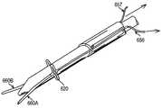
- a single loop actuation wire 654is used, as in the exemplary introducer assembly 510 ′ illustrated in FIGS. 27-32.
- the exemplary introducer assembly 510 ′is slidably disposed about a central guide wire 672 and comprises a guide rod 670 and a guide sheath 662 .
- the guide sheath 662includes a plurality of wire stabilization guides 660 , which may be integrated into the guide sheath 662 , or alternatively, be formed separately and coupled thereto.
- the wire stabilization guides 660generally comprise tubular members disposed around the outside diameter of the sheath, to hold the end portions 656 , 657 of the loop actuation wire 654 .
- Guide sheath 662is a tubular and has a circular cross-sectional shape, and has an inside diameter dimensioned to slide over the guide rod 670 . It is equally contemplated that the guide sheath has an oval or non-circular cross-sectional shape. The sheath further includes one or more slits or weakened tear seams 686 to provide controlled expansion of portions of the guide sheath, as will be detailed below.
- the guide rod 670is a tubular member and includes at least one slot 682 formed therein for releasably holding the loop actuation wire 654 .
- the guide rodhas a main tubular body dimensioned to fit inside the guide sheath and has a tapered end 800 having an opening 802 at the tip to accept the central guide wire.
- at least one longitudinal slot 682may be formed in the guide rod 670 along its length.
- the width of the longitudinal slot 682 at the surface of the guide rod 670should be less than the outside diameter of the stabilization guides 660 or the loop actuation wire 654 , so that the stabilization guide and/or loop actuation wire 654 is held within the slot (as shown in FIG. 27) until released by the sliding action of the sheath over the guide rod, as described below.
- the loop actuation wire and/or wire guidescan be held in a slot or slit formed in the guide rod (which may define a separate lumen structure in the guide rod), or alternatively the slot can be formed with a diameter less than the width of the wire or wire stabilization guide to permit the wire or wire stabilization guide to friction fit into the slot.
- the slot 682may be bounded by a pair of recessed areas 658 , 659 , so that, for example, the wire does not catch on tissue as the guide rod is inserted and removed from an artery or vein.
- slitsmay be formed in the material of the rod such that the loop actuation wire 654 is releasably held to the guide rod in a friction fit manner, and released from the guide rod in a similar manner as described above.
- one end portion 656 of the loop actuation wire 654is threaded inwardly into one end of the slot 682 at the first recessed area 658 and back outwardly from the slot 682 at the second recessed area 659 in the guide rod 670 .
- the other end portion 657 of the loop actuation wire 654may be threaded through a second slot (not shown), which may optionally include a set of recessed areas (not shown) on the opposing side of the guide rod 670 , or elsewhere along its length.
- the slot 682may be located along the length of the guide rod 670 . For example, as shown in FIGS. 27-32, the slot 682 is located along a line parallel to the central axis of the guide rod 670 .
- the slotbe formed in this manner, nor that the slot include recessed areas at its ends.
- the phrase “along the length of the guide rod” or “along its length”may mean generally longitudinally along the central axis of the guide rod, or may alternatively mean a slot formed in any orientation, since the slot and/or recessed areas 658 , 659 merely serve to releasably hold the wire stabilization guides 660 and/or ends 656 , 657 of the loop activation wire in place, and one of any number of configurations of slot 682 and/or recessed areas 658 , 659 may suffice.
- an opening 804 within the guide rodmay be provide to expose a portion of the central guide wire 672 .
- the central guide wire 672can then be placed over the loop portion 680 of the loop actuation wire 654 to secure the loop to the guide rod until the central guide wire is removed.
- the wire forming the wire actuation loophas a generally circular cross section.
- the wire stabilization guides 660 and slot 682may comprise one or more internal mating components adapted to mate with end portions 656 , 657 of the loop actuation wire 654 , in which case the end portions 656 , 657 would comprise one or more appropriate corresponding mating components.
- FIGS. 39 and 39Adepict cross-sectional views of the guide rod 670 of this exemplary embodiment.
- the guide rod 670includes a plurality of lumens: 802 , 804 , 806 and 808 .
- Lumens 808 and 806are included as a blood marking passageway (described above) and a wire guide passageway, respectively.
- Lumens 806 and 808are shown adjacent one another, but these lumens could also be formed coaxial with on another (e.g., the wire guide lumen inside of the blood marking lumen).
- Lumens 802 and 804releasably hold the loop actuation wire therein, and run along the length of the guide rod, for example, as shown in FIG. 27 .
- Lumens 802 and 804are shown on opposing sides of the guide rod. But it is equally contemplated that the lumens need not be disposed at opposition, but rather may be formed at any angle with respect to one another.
- a slit 810may be provided such that the loop actuation wire is held in lumen 802 / 804 until outward pressure forces the wire to “pop” out of the slit 810 .
- the material surrounding the slitmay comprise material of reduced durometer (with respect to the rest of the guide rod) such that the actuation wire can slide into and out of the lumen.
- a slotmay be formed as depicted in FIG. 40 A.
- the slot 812is defined by truncated lobes 814 and 816 .
- Lobes 814 and 816may also comprise material of reduced durometer with respect to the remaining portions of the guide rod.
- Slot 812can be dimensioned for a particular gage wire inserted therein.
- lumens 804 and 802are depicted as having generally circular cross-sectional shapes, the present invention equally contemplates other shapes, as may be dictated by the cross-sectional shape of the loop actuation wire (although the cross sectional shape of the wire stabilization guide, loop actuation wire and the lumen need not match).
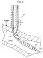
- FIG. 27illustrates, the introducer 510 ′ is initially inserted into the percutaneous puncture over the central guide wire 672 (already in the artery), which tracks into the puncture site, and is inserted into the artery.
- the central guide wire 672may be removed from the introducer assembly 510 ′, as shown.
- removing the central guide wire 672allows the loop activation wire 654 to be freely released from the guide rod 670 through the longitudinal apertures 682 within the guide rod 670 .
- the stabilization guides 660may be secured and actuated by pulling the loop actuation wire 654 at one or both end portions 656 , 657 until the distal ends of the stabilization guides 660 approximate to form a stabilization loop portion 680 .
- slits 686 or weakened tear seamsare formed in the distal end of the guide sheath 662 to allow the diameter of the guide sheath 662 to increase when an outwardly radial force is applied to the distal end of the guide sheath 662 , for example by the expansion of the loop portion of the loop actuation wire 654 .
- the foregoing actionprovides opposing forces outwardly to the central axis of the guide sheath 662 , thereby causing the end of the guide sheath 662 to separate at its slits 686 . Additional clearance for the expansion of a closure device (not shown) within the guide sheath 662 is thus provided. Furthermore, the tissue that is stretched by the stabilization guides 660 is caused to slide along the newly ramped angles of the stabilization guides 660 and be forced against the distal end of the guide sheath 662 . Moreover, the foregoing action aids in retaining the guide sheath 662 within the puncture against the vessel.
- the closure modalitye.g., a staple, as described hereinabove
- tensionmay then be applied to a single end 657 of the loop actuation wire 654 until the wire 654 is completely removed from the plurality of stabilization guides 660 , thereby freeing the distal ends of the stabilization guides 660 and allowing them to slide out of the vessel puncture on either side of the closure device (not shown). Finally, the guide sheath 662 assembly may be removed from the puncture site.
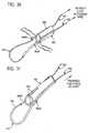
- the wire stabilization guides 660 A and 660 B depicted in FIGS. 30-32are generally formed as tubular structures having an inside diameter sufficient to pass the wire ends 656 , 657 therethrough.
- the guide 660 A and 660 Bare drawn together (FIG. 31) to form the loop.
- the wire stabilization guides 660 A and 660 B in combination with the loop activation wireto the stiffness of the combined area, since it is intended that the closure of the guides causes sufficient outward force to expand the sheath along the slot or weakened tear seams, i.e. by creating a loop causing these outward forces.
- the lengthsmay be selected to be equal or non-equal without departing from the present invention.
- the positions of the wire guides 660 A and 660 Bare depicted on opposing sides of the sheath. While this arrangement will provide a more accurate centering of the sheath on the wound site, it is contemplated herein that for certain procedures centering on the wound site may not be necessary, critical, or accurate, and thus, the positions of the wire stabilization guides can be at locations about the sheath other than at opposition.
- the description of the slots in the guide rod to releasably hold the wire stabilization guidesare formed in a location most convenient for placing the wire guides into the slots.
- the slotsmay be defined such that one slot releasably holds the wire stabilization guide with the wire inserted therethrough, and the other slot is dimensioned to releasably hold just the wire (as may be the case when the lengths of the wire stabilization guides differ). Still other modification may be made.
- a single or multi-lumen sheath devicemay be stabilized in direct approximation to an arterial, venous or other lumenal puncture.
- the foregoing described methodallows the positioning of a closure modality directly centered over such a puncture.
- the foregoing described introducer assembly 510 ′allows the distal end of the sheath 662 through which the closure device is introduced to be drawn against the artery, vein or other lumen, thereby aiding in sealing the puncture site to prevent leakage, as well as stabilizing the sheath 662 directly over the wound site.
- the foregoing described stabilization loop portionmay be replaced with a stabilization loop portion 680 ′ comprising a loop actuation wire 654 , and wire stabilization guides 660 having at least one reinforced section 666 .
- the reinforced sectionmay comprise an area of increased material or combination of materials, e.g., a section of the actuation wire 654 or stabilization guide 660 with greater individual or combined rigidity.
- the location of the reinforced section 666may be manipulated with respect to the wound site to control the shape of the stabilization loop portion 680 ′.
- the stabilization guides 660may be secured and actuated by pulling the loop actuation wire 654 at one or both end portions 656 , 657 until the distal ends of the stabilization guides 660 approximate to form a stabilization loop portion 680 ′ which comprises the reinforced section 666 , the central axis of which is generally perpendicular to the central axis of the guide sheath 662 , thereby providing opposing forces outwardly perpendicular to the central axis of the guide sheath 662 and causing the end of the guide sheath 662 to separate at its slits 686 .
- the loop portion and reinforced sectionforms a shape with the general appearance of coat hanger. Additional clearance for the expansion of a closure device (not shown) within the guide sheath 662 may likewise be provided.
- the tissue which is stretched by the stabilization guides 660is caused to slide along the newly ramped angles of the stabilization guides 660 and be forced against the distal end of the guide sheath 662 .
- the foregoing actionaids in retaining the guide sheath 662 within the puncture against the vessel.
- the closure modalitye.g., a staple, as described hereinabove
- tensionmay then be applied to a single end 657 of the loop actuation wire 654 until the wire 654 is completely removed from the plurality of stabilization guides 660 , thereby freeing the distal ends of the stabilization guides 660 and allowing them to slide out of the vessel puncture on either side of the closure device (not shown).
- the guide sheath 662 assemblymay be removed from the puncture site.
- the distal end of the first blood marking lumenis at an interluminal blood marking port 674 located at a predetermined point along the guide rod 670 , and the proximal end of the first blood marking lumen is an interluminal flashback port 684 for observing the presence of blood at the interluminal blood marking port 674 .
- the distal end of the second blood marking lumenis an exraluminal blood marking port 675 located approximately at the distal end of the guide sheath 662 , and the proximal end of the second blood marking lumen is an extraluminal flashback port 688 for observing the presence of blood at the extraluminal blood marking port 675 .
- the introducer assembly 510 ′is introduced into the percutaneous puncture which tracks into the puncture site, as described hereinabove.
- the location at which the guide sheath 662 has reached the approximate location of the artery or venous outer wallmay be identified by observing the pressurized blood flow from the internal flashback port 684 , which enters the internal blood marking port 674 when the internal blood marking port 674 has reached the inner lumen of the vessel.
- the absence of pressurized blood flow observed at the internal flashback port 684indicates that the guide sheath 662 has not yet reached the vessel outer wall.
- the fact that the guide sheath 662 has not entered the inner lumen of the vesselmay be confirmed by the absence of pressurized blood flow observed at the external flashback port 688 , which enters the extraluminal blood marking port 675 only if the extraluminal blood marking port 675 has reached the inner lumen of the vessel. Likewise, presence of blood in this lumen indicates the guide is too far into the artery or vein. The presence of pressurized blood flow at the internal flashback port 684 and absence of pressurized blood flow at the external flashback port 688 indicate that the distal end of the guide sheath 662 is adjacent to the arterial or venous outer wall.
- FIGS. 37 and 38depict alternative embodiments for bloodmarking.
- the BM lumen 540includes a sensor 700 (e.g., differential pressure transducer, flow sensor, electrodes, etc.) to detect the presence of fluid or fluid flow thereon.
- the wiring for the sensorcan be routed through the lumen 540 , as shown, to transmit a signal of the pressure (or presence of fluid) at the sensor 700 .
- an optical fiber 702is placed in lumen 540 for direct viewing of the area around BM port.
- the foregoing-described stepsprovide a method for identifying the depth of insertion of the transluminal device into an artery or vein based on the presence of pressurized blood internal to the vessel and the absence of pressurized blood external to the vessel.
- more than two blood marking points, lumens, and portsmay be provided to further aid in determining precisely the depth of the inserted transluminal device.
- the foregoing described insertion depth identifying techniquemay have utility in other contexts, as well, and those skilled in the art will recognize that the foregoing technique should not be limited to the context described hereinabove.
- either the stabilization loop portion 680 or 680 ′, or the guide sheath 662may therefore be approximated to tissue surrounding the wound site, so as to cause spring tension against the surrounding tissue, thereby aiding in approximately centering an introducer about the wound site, as well as in allowing opposing sides of the tissue surrounding the wound site to approximate one another.
- alternatives of the embodiments described abovemay be implemented consistent with the invention for stretching the wound site and for centrally locating procedures at the wound site.
- loop portions 680 and 680 ′provide a force to the wire and the guide sheath to spread the sheath outwardly and to approximate opposing portions of the wound site, as shown and described.
- the guide sheathcan be formed having a biasing mechanism that forces the sheath into the opened or spread position as shown in FIGS. 31 and 36.
- this sheathmay further comprise members on either side (such as the wire guides or shortened variations thereof shown in the embodiment of FIGS. 20A-22A) that provide the aforementioned outwardly opposing forces on the tissue surrounding the wound site.
- the wire forming the loop structure described hereinmay be provided as a single continuous loop that is pre-threaded into the wire stabilization guides. In this case, the loop is closed by pulling on the free end of the loop.
- the wiremay be snipped or cut so that it can be pulled free of the sheath and the wire stabilization guides.
- the sheathmay be adapted with holding mechanisms (not shown) to hold the ends of the wire in place once the doctor has pulled on the free ends to form the loop. Still other modifications may be made.
- the present inventioncontemplates that this arrangement can be replaced with a single elongated member (e.g. similar to the wire stabilization guide described herein) affixed to the guide sheath on opposing sides so that pulling this member forms the loop as shown in the drawings.
- the wire stabilization guide and wire described abovemay be replaced with a single member of sufficient modulus to for the loop as set forth herein.
- the wire described hereinmay comprise a tube, filament, stranded filaments, or other structures that are equivalent.
- stabilization guideshave been described herein as being generally tubular so that wire can be threaded therethrough.
- the stabilization guides and wirecould be coupled together in other configuration, for example, sliding engagement that may comprise a tongue-and-groove coupling, dovetail coupling, or other arrangement that would permit relative motion between the stabilization guides and the wire, while still providing mechanical strength along at least one axis.
- FIGS. 40-45depict another exemplary embodiment of the introducer of the present invention.
- the wire stabilization guidesare modified to include intralumenal support for procedures being performed at the vascular puncture site such as closure of the puncture or an anastomosis procedure.
- FIG. 40depicts a similar introducer as shown in FIGS. 20-26, except in this exemplary embodiment the wire stabilization guides 680 comprise a retention device 820 formed along a portion of the guide.
- FIGS. 41-45Deployment of the retention device is depicted in FIGS. 41-45.
- the wire stabilization guides 680are deployed by moving the guide rod 654 with respect to the sheath 660 .
- the retention device 820is formed along the length of the wire stabilization guide at a predetermined distance from the end of the sheath.
- One utility of the retention device 820is to ensure the sheath 660 remains located on the wound site, so the predetermined distance of the retention device from the end of the sheath may be chosen, for example, in accordance with the thickness of the tissue in which the device is deployed.
- FIG. 43depicts the sheath and stabilization guides in a deployed position.
- the retention device formed on each stabilization guidesecures the sheath to the arterial wall to prevent transverse movement of the sheath with respect to the wound site.
- the retention device 820 of this embodimentis essentially an expanding portion of the wire stabilization guide.
- FIG. 44Adepicts the retention device deployed into the expanded position.
- the device 820is formed by a split 822 on each side of the stabilization guide 680 .
- the loop actuation wireis affixed to the wire stabilization guide, for example, at point 824 .
- the wire656 , 657
- the wireis pulled proximally, thus causing the distal end of the wire stabilization guide to be drawn proximally, and causing the retention device to compress and buckle at the split sections (by placing a tensile load on the stabilization guide).
- the wireis moved distally, thereby releasing tension on the stabilization guide, as shown in FIG. 45 .
- compression on the stabilization guide to form the retention devicemay also be used to expand the distal tip of the sheath at the slits or weakened tear seams 686 , as shown in the relaxed position (FIG. 43B) and expanded position (FIGS. 43 A and C).
- FIGS. 44-48depict yet another exemplary embodiment of the introducer of the present invention.
- This embodimentis similar to the embodiment of FIGS. 27-34, except in this exemplary embodiment the wire stabilization guides 680 comprise a retention device 820 formed along a portion of the guide.
- the loop actuation wireforms a single loop, with a retention device 820 positioned on one or bothwire stabilization guide adjacent the sheath.
- Other features depicted in the Figuresare the same as the previous embodiment, described above.
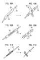
- FIGS. 49-55depict numerous exemplary embodiments of the retention device of the present invention.
- FIGS. 49A and 49Bdepict detailed views of the retention device 820 of the previous embodiment in the relaxed (static) and deployed positions, respectively.
- the retention device 820 ′comprises a tubular member with a hollowed out notch portion 824 formed along the length thereof. Compression of the tubular member causes the material opposite the notch to collapse thereby forming the retention device (FIG. 50 B).
- the retention device 820 ′′comprises a tubular member with a plurality of filaments 826 that fold (upon compression) to form the retention device. In this case, a small loop is formed.
- the slotsoverlap forming a through-hole approximately equal to the inside diameter of the tube.
- the cross section of the tube in the area of the slotis that of a U-shaped beam. Compression causes the tubular member to fold at the notched sections 840 and 842 , fulcruming on the wire at the location where the slots overlap, as shown in FIGS. 52B and 52C.
- FIG. 53depicts yet another exemplary embodiment of a retention device 900 that is similar to the example shown in FIG. 51, except the retention device 900 comprises a single strand member between a stationary member 904 and a moveable member 906 .
- the moveable member 906is moved over the wire guide 660 towards the stationary member 904 buckling the strand, as shown in FIG. 53 B.
- the moveable member 906is brought closer to the stationary member 904 to form a loop from the strand 902 .
- the strand 902 ′is disposed off-line (i.e., off axis) between the stationary member 904 and the moveable member 906 (FIG. 54 A). Movement of the moveable member 906 forms a loop as shown in FIG. 54 B.
- the retention device of the present inventionmay be viewed as an extension or lobe formed on one or both stabilization guides (FIGS. 40 - 45 ), or, in the case of the loop structure of FIGS. 46-48, the retention device may be formed on opposing sides of the loop, as shown.
- the retention device examples of FIGS. 49-55are intended to apply to both the embodiments of FIGS. 40-45 and 46 - 48 .
- the orientation of the retention device with respect to the wire stabilization guide or loopis depicted as generally perpendicular thereto, but the retention device may be formed from greater than 0 degrees to less than 180 degrees from wire stabilization guide or loop and still work as intended. The present invention covers all such alternatives.
- the orientation of the retention device with respect to the wound openingis depicted, for example in FIGS. 43, 45 and 47 , as being generally perpendicular to the long axis of the wound. However, this angle is not a requirement of the present invention, but rather the retention device can be disposed at any angle with respect to the long axis of the wound.
Landscapes
- Health & Medical Sciences (AREA)
- Life Sciences & Earth Sciences (AREA)
- Surgery (AREA)
- Heart & Thoracic Surgery (AREA)
- Engineering & Computer Science (AREA)
- Biomedical Technology (AREA)
- Nuclear Medicine, Radiotherapy & Molecular Imaging (AREA)
- Medical Informatics (AREA)
- Molecular Biology (AREA)
- Animal Behavior & Ethology (AREA)
- General Health & Medical Sciences (AREA)
- Public Health (AREA)
- Veterinary Medicine (AREA)
- Cardiology (AREA)
- Surgical Instruments (AREA)
Abstract
Description
Claims (2)
Priority Applications (9)
| Application Number | Priority Date | Filing Date | Title |
|---|---|---|---|
| US09/915,107US6533762B2 (en) | 2000-09-01 | 2001-07-25 | Advanced wound site management systems and methods |
| US10/036,690US7074232B2 (en) | 2000-09-01 | 2001-12-21 | Advanced wound site management systems and methods |
| JP2003504827AJP2005503195A (en) | 2001-06-19 | 2002-06-19 | Advanced wound management system and method |
| EP02742185AEP1424929A2 (en) | 2001-06-19 | 2002-06-19 | Advanced wound site management systems and methods |
| PCT/US2002/019316WO2002102236A2 (en) | 2001-06-19 | 2002-06-19 | Advanced wound site management systems and methods |
| AU2002315339AAU2002315339A1 (en) | 2001-06-19 | 2002-06-19 | Advanced wound site management systems and methods |
| CA002451084ACA2451084A1 (en) | 2001-06-19 | 2002-06-19 | Advanced wound site management systems and methods |
| US10/350,268US7198631B2 (en) | 2000-09-01 | 2003-01-23 | Advanced wound site management systems and methods |
| US10/636,072US20040093024A1 (en) | 2000-09-01 | 2003-08-06 | Advanced wound site management systems and methods |
Applications Claiming Priority (3)
| Application Number | Priority Date | Filing Date | Title |
|---|---|---|---|
| US23023400P | 2000-09-01 | 2000-09-01 | |
| US09/658,786US6322580B1 (en) | 2000-09-01 | 2000-09-11 | Wound site management and wound closure device |
| US09/915,107US6533762B2 (en) | 2000-09-01 | 2001-07-25 | Advanced wound site management systems and methods |
Related Parent Applications (2)
| Application Number | Title | Priority Date | Filing Date |
|---|---|---|---|
| US09/658,786Continuation-In-PartUS6322580B1 (en) | 2000-09-01 | 2000-09-11 | Wound site management and wound closure device |
| US09/884,782Continuation-In-PartUS6755842B2 (en) | 2000-09-01 | 2001-06-19 | Advanced wound site management systems and methods |
Related Child Applications (2)
| Application Number | Title | Priority Date | Filing Date |
|---|---|---|---|
| US10/036,690Continuation-In-PartUS7074232B2 (en) | 2000-09-01 | 2001-12-21 | Advanced wound site management systems and methods |
| US10/350,268ContinuationUS7198631B2 (en) | 2000-09-01 | 2003-01-23 | Advanced wound site management systems and methods |
Publications (2)
| Publication Number | Publication Date |
|---|---|
| US20020107542A1 US20020107542A1 (en) | 2002-08-08 |
| US6533762B2true US6533762B2 (en) | 2003-03-18 |
Family
ID=26924043
Family Applications (2)
| Application Number | Title | Priority Date | Filing Date |
|---|---|---|---|
| US09/915,107Expired - Fee RelatedUS6533762B2 (en) | 2000-09-01 | 2001-07-25 | Advanced wound site management systems and methods |
| US10/350,268Expired - Fee RelatedUS7198631B2 (en) | 2000-09-01 | 2003-01-23 | Advanced wound site management systems and methods |
Family Applications After (1)
| Application Number | Title | Priority Date | Filing Date |
|---|---|---|---|
| US10/350,268Expired - Fee RelatedUS7198631B2 (en) | 2000-09-01 | 2003-01-23 | Advanced wound site management systems and methods |
Country Status (1)
| Country | Link |
|---|---|
| US (2) | US6533762B2 (en) |
Cited By (90)
| Publication number | Priority date | Publication date | Assignee | Title |
|---|---|---|---|---|
| US20030109890A1 (en)* | 2000-09-01 | 2003-06-12 | Glenn Kanner | Advanced wound site management systems and methods |
| US20030199924A1 (en)* | 2000-09-08 | 2003-10-23 | James Coleman | Surgical stapler |
| US20040028502A1 (en)* | 2001-06-07 | 2004-02-12 | Christy Cummins | Surgical staple |
| US20040098043A1 (en)* | 2002-07-09 | 2004-05-20 | Trout Hugh H. | Delivery apparatus for use during a surgical procedure and method of using the same |
| US20040220596A1 (en)* | 2003-02-04 | 2004-11-04 | Frazier Andrew G.C. | Patent foramen ovale closure system |
| US20040236355A1 (en)* | 2001-08-09 | 2004-11-25 | Thomas Anthony | Surgical stapling device |
| US20040249391A1 (en)* | 2001-08-09 | 2004-12-09 | Christy Cummins | Surgical stapling device and method |
| US20050119695A1 (en)* | 2000-12-07 | 2005-06-02 | Carley Michael T. | Closure device and methods for making and using them |
| US20050187568A1 (en)* | 2004-02-20 | 2005-08-25 | Klenk Alan R. | Devices and methods for closing a patent foramen ovale with a coil-shaped closure device |
| US20050256537A1 (en)* | 2002-07-03 | 2005-11-17 | Christy Cummins | Surgical stapling device |
| US20060111741A1 (en)* | 2004-11-23 | 2006-05-25 | Instrasurgical, Llc | Wound closure device |
| US20060190014A1 (en)* | 2000-01-05 | 2006-08-24 | Ginn Richard S | Integrated vascular device with puncture site closure component and sealant and methods of use |
| US20060208028A1 (en)* | 2000-09-01 | 2006-09-21 | Glenn Kanner | Wound site management and wound closure device |
| US20060217744A1 (en)* | 2005-03-28 | 2006-09-28 | Cardica, Inc. | Vascular closure system |
| US20060264978A1 (en)* | 2005-05-17 | 2006-11-23 | Belhe Kedar R | Puncture locating device |
| US20070106327A1 (en)* | 2001-08-01 | 2007-05-10 | Ev3 Endovascular, Inc. | Tissue opening occluder |
| US20070270906A1 (en)* | 2006-05-17 | 2007-11-22 | Sdgi Holdings, Inc. | Surgical staple assembly |
| US20080071294A1 (en)* | 2006-09-15 | 2008-03-20 | Bender Theodore M | Apparatus and method for closure of patent foramen ovale |
| US20080091079A1 (en)* | 2004-11-17 | 2008-04-17 | Satiety, Inc. | Remote tissue retraction device |
| US20080140013A1 (en)* | 2003-04-30 | 2008-06-12 | Kunkel Sanford S | Portal Device |
| US20080177300A1 (en)* | 2007-01-24 | 2008-07-24 | Medtronic Vascular, Inc. | Low-Profile Vasculare Closure Systems and Methods of Using Same |
| US20080217376A1 (en)* | 2007-03-08 | 2008-09-11 | Cardica, Inc. | Surgical Stapler |
| US7458978B1 (en) | 2005-03-28 | 2008-12-02 | Cardica, Inc. | Vascular closure system utilizing a staple |
| US20090093826A1 (en)* | 2007-10-05 | 2009-04-09 | Cardica, Inc. | Patent Foramen Ovale Closure System |
| US7533790B1 (en) | 2007-03-08 | 2009-05-19 | Cardica, Inc. | Surgical stapler |
| US20090254121A1 (en)* | 2008-04-02 | 2009-10-08 | Cardica, Inc. | Vascular Closure with Multi-Pronged Clip |
| US20090264923A1 (en)* | 2008-04-17 | 2009-10-22 | Medtronic Vascular, Inc | Vascular Puncture Stapling System |
| US20100042144A1 (en)* | 2008-08-12 | 2010-02-18 | Steven Bennett | Medical Device for Wound Closure and Method of Use |
| USD611144S1 (en) | 2006-06-28 | 2010-03-02 | Abbott Laboratories | Apparatus for delivering a closure element |
| US20100087854A1 (en)* | 2008-08-12 | 2010-04-08 | Joshua Stopek | Medical device for wound closure and method of use |
| US20100204656A1 (en)* | 2009-02-06 | 2010-08-12 | Interrad Medical, Inc. | System for anchoring medical devices |
| US7806904B2 (en) | 2000-12-07 | 2010-10-05 | Integrated Vascular Systems, Inc. | Closure device |
| US7806910B2 (en) | 2002-11-26 | 2010-10-05 | Abbott Laboratories | Multi-element biased suture clip |
| US7819895B2 (en) | 2000-01-05 | 2010-10-26 | Integrated Vascular Systems, Inc. | Vascular sheath with bioabsorbable puncture site closure apparatus and methods of use |
| US7828817B2 (en) | 2000-01-05 | 2010-11-09 | Integrated Vascular Systems, Inc. | Apparatus and methods for delivering a closure device |
| US7842068B2 (en) | 2000-12-07 | 2010-11-30 | Integrated Vascular Systems, Inc. | Apparatus and methods for providing tactile feedback while delivering a closure device |
| US7841502B2 (en) | 2007-12-18 | 2010-11-30 | Abbott Laboratories | Modular clip applier |
| US7850797B2 (en) | 2002-12-31 | 2010-12-14 | Integrated Vascular Systems, Inc. | Methods for manufacturing a clip and clip |
| US7850709B2 (en) | 2002-06-04 | 2010-12-14 | Abbott Vascular Inc. | Blood vessel closure clip and delivery device |
| US20100327042A1 (en)* | 2008-03-14 | 2010-12-30 | Amid Parviz K | Hernia stapler with integrated mesh manipulator |
| US7867249B2 (en) | 2003-01-30 | 2011-01-11 | Integrated Vascular Systems, Inc. | Clip applier and methods of use |
| US7879071B2 (en) | 2000-12-07 | 2011-02-01 | Integrated Vascular Systems, Inc. | Closure device and methods for making and using them |
| US7931669B2 (en) | 2000-01-05 | 2011-04-26 | Integrated Vascular Systems, Inc. | Integrated vascular device with puncture site closure component and sealant and methods of use |
| US8007512B2 (en) | 2002-02-21 | 2011-08-30 | Integrated Vascular Systems, Inc. | Plunger apparatus and methods for delivering a closure device |
| US8048108B2 (en) | 2005-08-24 | 2011-11-01 | Abbott Vascular Inc. | Vascular closure methods and apparatuses |
| US8202293B2 (en) | 2003-01-30 | 2012-06-19 | Integrated Vascular Systems, Inc. | Clip applier and methods of use |
| US8202294B2 (en) | 2003-01-30 | 2012-06-19 | Integrated Vascular Systems, Inc. | Clip applier and methods of use |
| US8226681B2 (en) | 2007-06-25 | 2012-07-24 | Abbott Laboratories | Methods, devices, and apparatus for managing access through tissue |
| US8303624B2 (en) | 2010-03-15 | 2012-11-06 | Abbott Cardiovascular Systems, Inc. | Bioabsorbable plug |
| US8313497B2 (en) | 2005-07-01 | 2012-11-20 | Abbott Laboratories | Clip applier and methods of use |
| US8323312B2 (en) | 2008-12-22 | 2012-12-04 | Abbott Laboratories | Closure device |
| US8398656B2 (en) | 2003-01-30 | 2013-03-19 | Integrated Vascular Systems, Inc. | Clip applier and methods of use |
| US8398676B2 (en) | 2008-10-30 | 2013-03-19 | Abbott Vascular Inc. | Closure device |
| US8556932B2 (en) | 2011-05-19 | 2013-10-15 | Abbott Cardiovascular Systems, Inc. | Collapsible plug for tissue closure |
| US8556930B2 (en) | 2006-06-28 | 2013-10-15 | Abbott Laboratories | Vessel closure device |
| US8590760B2 (en) | 2004-05-25 | 2013-11-26 | Abbott Vascular Inc. | Surgical stapler |
| US8603116B2 (en) | 2010-08-04 | 2013-12-10 | Abbott Cardiovascular Systems, Inc. | Closure device with long tines |
| US8617184B2 (en) | 2011-02-15 | 2013-12-31 | Abbott Cardiovascular Systems, Inc. | Vessel closure system |
| US8672953B2 (en) | 2007-12-17 | 2014-03-18 | Abbott Laboratories | Tissue closure system and methods of use |
| US8690910B2 (en) | 2000-12-07 | 2014-04-08 | Integrated Vascular Systems, Inc. | Closure device and methods for making and using them |
| US8758399B2 (en) | 2010-08-02 | 2014-06-24 | Abbott Cardiovascular Systems, Inc. | Expandable bioabsorbable plug apparatus and method |
| US8758398B2 (en) | 2006-09-08 | 2014-06-24 | Integrated Vascular Systems, Inc. | Apparatus and method for delivering a closure element |
| US8758400B2 (en) | 2000-01-05 | 2014-06-24 | Integrated Vascular Systems, Inc. | Closure system and methods of use |
| US8808310B2 (en) | 2006-04-20 | 2014-08-19 | Integrated Vascular Systems, Inc. | Resettable clip applier and reset tools |
| US8821534B2 (en) | 2010-12-06 | 2014-09-02 | Integrated Vascular Systems, Inc. | Clip applier having improved hemostasis and methods of use |
| US8858594B2 (en) | 2008-12-22 | 2014-10-14 | Abbott Laboratories | Curved closure device |
| US8870049B2 (en) | 2008-03-14 | 2014-10-28 | Transenterix, Inc. | Hernia stapler |
| US8893947B2 (en) | 2007-12-17 | 2014-11-25 | Abbott Laboratories | Clip applier and methods of use |
| US8905937B2 (en) | 2009-02-26 | 2014-12-09 | Integrated Vascular Systems, Inc. | Methods and apparatus for locating a surface of a body lumen |
| US8920442B2 (en) | 2005-08-24 | 2014-12-30 | Abbott Vascular Inc. | Vascular opening edge eversion methods and apparatuses |
| US8926633B2 (en) | 2005-06-24 | 2015-01-06 | Abbott Laboratories | Apparatus and method for delivering a closure element |
| US9056187B2 (en) | 2008-07-16 | 2015-06-16 | Interrad Medical, Inc. | Anchor systems and methods |
| US9089674B2 (en) | 2000-10-06 | 2015-07-28 | Integrated Vascular Systems, Inc. | Apparatus and methods for positioning a vascular sheath |
| US9089311B2 (en) | 2009-01-09 | 2015-07-28 | Abbott Vascular Inc. | Vessel closure devices and methods |
| US20150250461A1 (en)* | 2012-09-26 | 2015-09-10 | Eric Berreklouw | Constrictor for closing or narrowing a passage through tissue of a hollow organ |
| US9149276B2 (en) | 2011-03-21 | 2015-10-06 | Abbott Cardiovascular Systems, Inc. | Clip and deployment apparatus for tissue closure |
| US9173644B2 (en) | 2009-01-09 | 2015-11-03 | Abbott Vascular Inc. | Closure devices, systems, and methods |
| US9227040B2 (en) | 2002-09-20 | 2016-01-05 | Interrad Medical, Inc. | Temporary retention device |
| US9282965B2 (en) | 2008-05-16 | 2016-03-15 | Abbott Laboratories | Apparatus and methods for engaging tissue |
| US9314230B2 (en) | 2009-01-09 | 2016-04-19 | Abbott Vascular Inc. | Closure device with rapidly eroding anchor |
| US9332976B2 (en) | 2011-11-30 | 2016-05-10 | Abbott Cardiovascular Systems, Inc. | Tissue closure device |
| US9364209B2 (en) | 2012-12-21 | 2016-06-14 | Abbott Cardiovascular Systems, Inc. | Articulating suturing device |
| US9381323B2 (en) | 2006-03-09 | 2016-07-05 | Interrad Medical, Inc. | Anchor device and method |
| US9414824B2 (en) | 2009-01-16 | 2016-08-16 | Abbott Vascular Inc. | Closure devices, systems, and methods |
| US9414820B2 (en) | 2009-01-09 | 2016-08-16 | Abbott Vascular Inc. | Closure devices, systems, and methods |
| US9456811B2 (en) | 2005-08-24 | 2016-10-04 | Abbott Vascular Inc. | Vascular closure methods and apparatuses |
| US9486191B2 (en) | 2009-01-09 | 2016-11-08 | Abbott Vascular, Inc. | Closure devices |
| US9579091B2 (en) | 2000-01-05 | 2017-02-28 | Integrated Vascular Systems, Inc. | Closure system and methods of use |
| US9585647B2 (en) | 2009-08-26 | 2017-03-07 | Abbott Laboratories | Medical device for repairing a fistula |
| US12035899B2 (en) | 2018-02-28 | 2024-07-16 | Venock Medical Gmbh | Medical apparatus and method for closing an opening in a tissue |
Families Citing this family (61)
| Publication number | Priority date | Publication date | Assignee | Title |
|---|---|---|---|---|
| US8177762B2 (en) | 1998-12-07 | 2012-05-15 | C. R. Bard, Inc. | Septum including at least one identifiable feature, access ports including same, and related methods |
| US6533795B1 (en) | 2000-04-11 | 2003-03-18 | Opus Medical, Inc | Dual function suturing apparatus and method |
| US6755842B2 (en)* | 2000-09-01 | 2004-06-29 | Angiolink Corporation | Advanced wound site management systems and methods |
| US6770084B1 (en)* | 2002-06-26 | 2004-08-03 | Opus Medical, Inc. | Suture capture device |
| US8480706B2 (en) | 2003-07-14 | 2013-07-09 | W.L. Gore & Associates, Inc. | Tubular patent foramen ovale (PFO) closure device with catch system |
| US9861346B2 (en) | 2003-07-14 | 2018-01-09 | W. L. Gore & Associates, Inc. | Patent foramen ovale (PFO) closure device with linearly elongating petals |
| EP2481356B1 (en) | 2003-07-14 | 2013-09-11 | W.L. Gore & Associates, Inc. | Tubular patent foramen ovale (PFO) closure device with catch system |
| EP1667586A1 (en) | 2003-09-15 | 2006-06-14 | Abbott Laboratories | Suture locking device and methods |
| GB0420505D0 (en)* | 2004-09-14 | 2004-10-20 | Wild Andrew M | Apparatus for dispensing surgical clips |
| US9474888B2 (en) | 2005-03-04 | 2016-10-25 | C. R. Bard, Inc. | Implantable access port including a sandwiched radiopaque insert |
| US7947022B2 (en) | 2005-03-04 | 2011-05-24 | C. R. Bard, Inc. | Access port identification systems and methods |
| JP5484674B2 (en) | 2005-03-04 | 2014-05-07 | シー・アール・バード・インコーポレーテッド | Access port and identification method |
| US8029482B2 (en) | 2005-03-04 | 2011-10-04 | C. R. Bard, Inc. | Systems and methods for radiographically identifying an access port |
| US10307581B2 (en) | 2005-04-27 | 2019-06-04 | C. R. Bard, Inc. | Reinforced septum for an implantable medical device |
| EP1874393B1 (en) | 2005-04-27 | 2017-09-06 | C.R.Bard, Inc. | Infusion apparatuses |
| EP3884989B1 (en) | 2005-04-27 | 2022-07-13 | C. R. Bard, Inc. | Vascular access port |
| US20070167981A1 (en)* | 2005-12-22 | 2007-07-19 | Nmt Medical, Inc. | Catch members for occluder devices |
| US8562629B2 (en)* | 2006-10-24 | 2013-10-22 | Arthrocare Corporation | Suture device having selective needle actuation and related method |
| US9265912B2 (en) | 2006-11-08 | 2016-02-23 | C. R. Bard, Inc. | Indicia informative of characteristics of insertable medical devices |
| US9642986B2 (en) | 2006-11-08 | 2017-05-09 | C. R. Bard, Inc. | Resource information key for an insertable medical device |
| US20080228202A1 (en)* | 2007-03-16 | 2008-09-18 | Ethicon Endo-Surgery, Inc. | Endoscopic tissue approximation system |
| US20080228199A1 (en)* | 2007-03-16 | 2008-09-18 | Ethicon Endo-Surgery, Inc. | Endoscopic tissue approximation method |
| US9005242B2 (en) | 2007-04-05 | 2015-04-14 | W.L. Gore & Associates, Inc. | Septal closure device with centering mechanism |
| ES2651269T3 (en) | 2007-06-20 | 2018-01-25 | Medical Components, Inc. | Venous reservoir with molded indications and / or radiopacas |
| US9610432B2 (en) | 2007-07-19 | 2017-04-04 | Innovative Medical Devices, Llc | Venous access port assembly with X-ray discernable indicia |
| WO2009012385A1 (en) | 2007-07-19 | 2009-01-22 | Medical Components, Inc. | Venous access port assembly with x-ray discernable indicia |
| US9579496B2 (en) | 2007-11-07 | 2017-02-28 | C. R. Bard, Inc. | Radiopaque and septum-based indicators for a multi-lumen implantable port |
| US20130165967A1 (en) | 2008-03-07 | 2013-06-27 | W.L. Gore & Associates, Inc. | Heart occlusion devices |
| ES2906416T3 (en) | 2008-10-31 | 2022-04-18 | Bard Inc C R | Systems and methods to identify an access road |
| US8932271B2 (en) | 2008-11-13 | 2015-01-13 | C. R. Bard, Inc. | Implantable medical devices including septum-based indicators |
| US11890443B2 (en) | 2008-11-13 | 2024-02-06 | C. R. Bard, Inc. | Implantable medical devices including septum-based indicators |
| US8147505B2 (en)* | 2009-03-23 | 2012-04-03 | Arthrocare Corporation | Surgical instrument for manipulating surgical suture and methods of use |
| US20120029556A1 (en) | 2009-06-22 | 2012-02-02 | Masters Steven J | Sealing device and delivery system |
| US9636094B2 (en) | 2009-06-22 | 2017-05-02 | W. L. Gore & Associates, Inc. | Sealing device and delivery system |
| EP2451512A1 (en) | 2009-07-07 | 2012-05-16 | C.R. Bard Inc. | Extensible internal bolster for a medical device |
| US9211118B2 (en)* | 2009-11-16 | 2015-12-15 | Arthrocare Corporation | Suture passer |
| ES2695907T3 (en) | 2009-11-17 | 2019-01-11 | Bard Inc C R | Overmolded access port that includes anchoring and identification features |
| US20120022562A1 (en)* | 2010-07-23 | 2012-01-26 | Boston Scientific Scimed, Inc. | Device to detect internal bleeding |
| US8603137B2 (en) | 2010-11-01 | 2013-12-10 | Abbott Cardiovascular Systems, Inc. | Methods and systems for establishing hemostasis relative to a puncture |
| USD676955S1 (en) | 2010-12-30 | 2013-02-26 | C. R. Bard, Inc. | Implantable access port |
| USD682416S1 (en) | 2010-12-30 | 2013-05-14 | C. R. Bard, Inc. | Implantable access port |
| US8685047B2 (en)* | 2011-02-07 | 2014-04-01 | Abbott Vascular, Inc. | Scaffold device for preventing tissue trauma |
| US9149265B2 (en) | 2011-02-26 | 2015-10-06 | Abbott Cardiovascular Systems, Inc. | Hinged tissue support device |
| US9357997B2 (en) | 2011-07-08 | 2016-06-07 | Smith & Nephew, Inc. | Suture passer and method |
| US8951263B2 (en) | 2011-07-08 | 2015-02-10 | Smith & Nephew, Inc. | Orthopedic suture passer and method |
| US8801727B2 (en) | 2011-07-08 | 2014-08-12 | Smith & Nephew, Inc. | Orthopedic suture passer and method |
| US8882834B2 (en) | 2011-07-08 | 2014-11-11 | Smith & Nephew, Inc. | Soft tissue repair |
| US9662105B2 (en) | 2011-07-08 | 2017-05-30 | Smith & Nephew, Inc. | Suture passer and method |
| US8888849B2 (en) | 2011-07-08 | 2014-11-18 | Smith & Nephew, Inc. | Soft tissue repair |
| US9770232B2 (en) | 2011-08-12 | 2017-09-26 | W. L. Gore & Associates, Inc. | Heart occlusion devices |
| US9055932B2 (en) | 2011-08-26 | 2015-06-16 | Abbott Cardiovascular Systems, Inc. | Suture fastener combination device |
| US8845684B2 (en)* | 2011-11-30 | 2014-09-30 | Abbott Cardiovascular Systems, Inc. | Tissue closure device with resilient arms |
| US10265062B2 (en) | 2012-02-07 | 2019-04-23 | Arthrocare Corporation | Surgical instrument for manipulating and passing suture |
| US9138214B2 (en) | 2012-03-02 | 2015-09-22 | Abbott Cardiovascular Systems, Inc. | Suture securing systems, devices and methods |
| US8876848B2 (en)* | 2012-06-06 | 2014-11-04 | Stewart And Stien Enterprises, Llc | Dilator and elongate guide wire and method of using same |
| US9486132B2 (en)* | 2013-01-17 | 2016-11-08 | Abbott Cardiovascular Systems, Inc. | Access device for accessing tissue |
| US10828019B2 (en) | 2013-01-18 | 2020-11-10 | W.L. Gore & Associates, Inc. | Sealing device and delivery system |
| CA2915477A1 (en)* | 2013-06-25 | 2014-12-31 | Boston Scientific Scimed, Inc. | Hemostasis device with one way trap |
| US9808230B2 (en) | 2014-06-06 | 2017-11-07 | W. L. Gore & Associates, Inc. | Sealing device and delivery system |
| WO2017091812A1 (en)* | 2015-11-25 | 2017-06-01 | Talon Medical, LLC | Tissue engagement devices, systems, and methods |
| US11439383B2 (en) | 2019-08-20 | 2022-09-13 | Abbott Cardiovascular Systems, Inc. | Self locking suture and self locking suture mediated closure device |
Citations (11)
| Publication number | Priority date | Publication date | Assignee | Title |
|---|---|---|---|---|
| US4154242A (en)* | 1977-06-17 | 1979-05-15 | Zafmedico Corp. | Bladder catheter |
| US4380234A (en)* | 1979-08-16 | 1983-04-19 | Baxter Travenol Laboratories, Inc. | Infusion needle attachment |
| US4419819A (en)* | 1982-01-29 | 1983-12-13 | Medtronic, Inc. | Method of making biomedical lead with lobed lead anchor |
| US4565544A (en)* | 1983-02-12 | 1986-01-21 | Fresenius Ag | Device for introducing a catheter |
| US4772266A (en)* | 1987-05-04 | 1988-09-20 | Catheter Technology Corp. | Catheter dilator/sheath assembly and method |
| US4973313A (en)* | 1989-09-13 | 1990-11-27 | Sherwood Medical Company | Over the needle catheter introducer |
| US5290249A (en)* | 1990-10-09 | 1994-03-01 | Vance Products Incorporated | Surgical access sheath |
| US5409469A (en)* | 1993-11-04 | 1995-04-25 | Medtronic, Inc. | Introducer system having kink resistant splittable sheath |
| US5454365A (en)* | 1990-11-05 | 1995-10-03 | Bonutti; Peter M. | Mechanically expandable arthroscopic retractors |
| US5885217A (en)* | 1995-01-20 | 1999-03-23 | Tyco Group S.A.R.L. | Catheter introducer |
| US6162221A (en)* | 1997-10-29 | 2000-12-19 | Asahi Kogaku Kogyo Kabushiki Kaisha | Drainage tube introducer for endoscope |
Family Cites Families (46)
| Publication number | Priority date | Publication date | Assignee | Title |
|---|---|---|---|---|
| US4744364A (en) | 1987-02-17 | 1988-05-17 | Intravascular Surgical Instruments, Inc. | Device for sealing percutaneous puncture in a vessel |
| US4890612A (en) | 1987-02-17 | 1990-01-02 | Kensey Nash Corporation | Device for sealing percutaneous puncture in a vessel |
| USRE34866E (en) | 1987-02-17 | 1995-02-21 | Kensey Nash Corporation | Device for sealing percutaneous puncture in a vessel |
| US4852568A (en) | 1987-02-17 | 1989-08-01 | Kensey Nash Corporation | Method and apparatus for sealing an opening in tissue of a living being |
| US5330445A (en) | 1988-05-26 | 1994-07-19 | Haaga John R | Sheath for wound closure caused by a medical tubular device |
| US5129906A (en) | 1989-09-08 | 1992-07-14 | Linvatec Corporation | Bioabsorbable tack for joining bodily tissue and in vivo method and apparatus for deploying same |
| US5061274A (en) | 1989-12-04 | 1991-10-29 | Kensey Nash Corporation | Plug device for sealing openings and method of use |
| JP2528602B2 (en) | 1989-12-04 | 1996-08-28 | ケンゼー・ナッシュ・コーポレーション | Plug device for sealing the opening |
| US5391183A (en) | 1990-09-21 | 1995-02-21 | Datascope Investment Corp | Device and method sealing puncture wounds |
| US5192300A (en) | 1990-10-01 | 1993-03-09 | Quinton Instrument Company | Insertion assembly and method of inserting a vessel plug into the body of a patient |
| US5108421A (en) | 1990-10-01 | 1992-04-28 | Quinton Instrument Company | Insertion assembly and method of inserting a vessel plug into the body of a patient |
| US5141515A (en) | 1990-10-11 | 1992-08-25 | Eberbach Mark A | Apparatus and methods for repairing hernias |
| US5116357A (en) | 1990-10-11 | 1992-05-26 | Eberbach Mark A | Hernia plug and introducer apparatus |
| US5419765A (en) | 1990-12-27 | 1995-05-30 | Novoste Corporation | Wound treating device and method for treating wounds |
| US5275610A (en)* | 1991-05-13 | 1994-01-04 | Cook Incorporated | Surgical retractors and method of use |
| NL9101051A (en) | 1991-06-18 | 1993-01-18 | Ashridge Ag | CLOSING DEVICE FOR A VESSEL OR THE LIKE. |
| WO1993006878A1 (en) | 1991-10-11 | 1993-04-15 | Boston Scientific Corporation | Catheter introducer sheath assembly |
| US5290310A (en) | 1991-10-30 | 1994-03-01 | Howmedica, Inc. | Hemostatic implant introducer |
| US5282827A (en) | 1991-11-08 | 1994-02-01 | Kensey Nash Corporation | Hemostatic puncture closure system and method of use |
| US5411520A (en) | 1991-11-08 | 1995-05-02 | Kensey Nash Corporation | Hemostatic vessel puncture closure system utilizing a plug located within the puncture tract spaced from the vessel, and method of use |
| CA2134071C (en) | 1992-04-23 | 1999-04-27 | Sew Wah Tay | Apparatus and method for sealing vascular punctures |
| US5413571A (en) | 1992-07-16 | 1995-05-09 | Sherwood Medical Company | Device for sealing hemostatic incisions |
| US5292332A (en) | 1992-07-27 | 1994-03-08 | Lee Benjamin I | Methods and device for percutanceous sealing of arterial puncture sites |
| US5443481A (en) | 1992-07-27 | 1995-08-22 | Lee; Benjamin I. | Methods and device for percutaneous sealing of arterial puncture sites |
| US5415657A (en) | 1992-10-13 | 1995-05-16 | Taymor-Luria; Howard | Percutaneous vascular sealing method |
| US5304184A (en) | 1992-10-19 | 1994-04-19 | Indiana University Foundation | Apparatus and method for positive closure of an internal tissue membrane opening |
| US5478326A (en) | 1992-12-10 | 1995-12-26 | Shiu; Man F. | Arterial device for control of bleeding from a puncture in an artery wall |
| US5417699A (en) | 1992-12-10 | 1995-05-23 | Perclose Incorporated | Device and method for the percutaneous suturing of a vascular puncture site |
| US5320639A (en) | 1993-03-12 | 1994-06-14 | Meadox Medicals, Inc. | Vascular plug delivery system |
| US5391182A (en) | 1993-08-03 | 1995-02-21 | Origin Medsystems, Inc. | Apparatus and method for closing puncture wounds |
| US5462561A (en) | 1993-08-05 | 1995-10-31 | Voda; Jan K. | Suture device |
| US5496332A (en)* | 1994-10-20 | 1996-03-05 | Cordis Corporation | Wound closure apparatus and method for its use |
| US5810846A (en) | 1995-08-03 | 1998-09-22 | United States Surgical Corporation | Vascular hole closure |
| US6004341A (en) | 1996-12-05 | 1999-12-21 | Loma Linda University Medical Center | Vascular wound closure device |
| WO1998005259A1 (en) | 1996-08-06 | 1998-02-12 | Quinton Instrument Company | Insertion assembly and method of inserting a hemostatic closure device into an incision |
| US5861005A (en)* | 1997-02-11 | 1999-01-19 | X-Site, L.L.C. | Arterial stapling device |
| US6059800A (en) | 1997-09-10 | 2000-05-09 | Applied Medical Resources Corporation | Suturing apparatus and method |
| US5919207A (en)* | 1998-06-02 | 1999-07-06 | Taheri; Syde A. | Percutaneous arterial closure with staples |
| US6780197B2 (en) | 2000-01-05 | 2004-08-24 | Integrated Vascular Systems, Inc. | Apparatus and methods for delivering a vascular closure device to a body lumen |
| US6391048B1 (en) | 2000-01-05 | 2002-05-21 | Integrated Vascular Systems, Inc. | Integrated vascular device with puncture site closure component and sealant and methods of use |
| US6197042B1 (en) | 2000-01-05 | 2001-03-06 | Medical Technology Group, Inc. | Vascular sheath with puncture site closure apparatus and methods of use |
| US6461364B1 (en) | 2000-01-05 | 2002-10-08 | Integrated Vascular Systems, Inc. | Vascular sheath with bioabsorbable puncture site closure apparatus and methods of use |
| US6322580B1 (en)* | 2000-09-01 | 2001-11-27 | Angiolink Corporation | Wound site management and wound closure device |
| US6755842B2 (en)* | 2000-09-01 | 2004-06-29 | Angiolink Corporation | Advanced wound site management systems and methods |
| US6533762B2 (en)* | 2000-09-01 | 2003-03-18 | Angiolink Corporation | Advanced wound site management systems and methods |
| US6846319B2 (en) | 2000-12-14 | 2005-01-25 | Core Medical, Inc. | Devices for sealing openings through tissue and apparatus and methods for delivering them |
- 2001
- 2001-07-25USUS09/915,107patent/US6533762B2/ennot_activeExpired - Fee Related
- 2003
- 2003-01-23USUS10/350,268patent/US7198631B2/ennot_activeExpired - Fee Related
Patent Citations (11)
| Publication number | Priority date | Publication date | Assignee | Title |
|---|---|---|---|---|
| US4154242A (en)* | 1977-06-17 | 1979-05-15 | Zafmedico Corp. | Bladder catheter |
| US4380234A (en)* | 1979-08-16 | 1983-04-19 | Baxter Travenol Laboratories, Inc. | Infusion needle attachment |
| US4419819A (en)* | 1982-01-29 | 1983-12-13 | Medtronic, Inc. | Method of making biomedical lead with lobed lead anchor |
| US4565544A (en)* | 1983-02-12 | 1986-01-21 | Fresenius Ag | Device for introducing a catheter |
| US4772266A (en)* | 1987-05-04 | 1988-09-20 | Catheter Technology Corp. | Catheter dilator/sheath assembly and method |
| US4973313A (en)* | 1989-09-13 | 1990-11-27 | Sherwood Medical Company | Over the needle catheter introducer |
| US5290249A (en)* | 1990-10-09 | 1994-03-01 | Vance Products Incorporated | Surgical access sheath |
| US5454365A (en)* | 1990-11-05 | 1995-10-03 | Bonutti; Peter M. | Mechanically expandable arthroscopic retractors |
| US5409469A (en)* | 1993-11-04 | 1995-04-25 | Medtronic, Inc. | Introducer system having kink resistant splittable sheath |
| US5885217A (en)* | 1995-01-20 | 1999-03-23 | Tyco Group S.A.R.L. | Catheter introducer |
| US6162221A (en)* | 1997-10-29 | 2000-12-19 | Asahi Kogaku Kogyo Kabushiki Kaisha | Drainage tube introducer for endoscope |
Cited By (217)
| Publication number | Priority date | Publication date | Assignee | Title |
|---|---|---|---|---|
| US9579091B2 (en) | 2000-01-05 | 2017-02-28 | Integrated Vascular Systems, Inc. | Closure system and methods of use |
| US7931669B2 (en) | 2000-01-05 | 2011-04-26 | Integrated Vascular Systems, Inc. | Integrated vascular device with puncture site closure component and sealant and methods of use |
| US9050087B2 (en) | 2000-01-05 | 2015-06-09 | Integrated Vascular Systems, Inc. | Integrated vascular device with puncture site closure component and sealant and methods of use |
| US7828817B2 (en) | 2000-01-05 | 2010-11-09 | Integrated Vascular Systems, Inc. | Apparatus and methods for delivering a closure device |
| US7819895B2 (en) | 2000-01-05 | 2010-10-26 | Integrated Vascular Systems, Inc. | Vascular sheath with bioabsorbable puncture site closure apparatus and methods of use |
| US10111664B2 (en) | 2000-01-05 | 2018-10-30 | Integrated Vascular Systems, Inc. | Closure system and methods of use |
| US8758400B2 (en) | 2000-01-05 | 2014-06-24 | Integrated Vascular Systems, Inc. | Closure system and methods of use |
| US8758396B2 (en) | 2000-01-05 | 2014-06-24 | Integrated Vascular Systems, Inc. | Vascular sheath with bioabsorbable puncture site closure apparatus and methods of use |
| US7901428B2 (en) | 2000-01-05 | 2011-03-08 | Integrated Vascular Systems, Inc. | Vascular sheath with bioabsorbable puncture site closure apparatus and methods of use |
| US20060190014A1 (en)* | 2000-01-05 | 2006-08-24 | Ginn Richard S | Integrated vascular device with puncture site closure component and sealant and methods of use |
| US8956388B2 (en) | 2000-01-05 | 2015-02-17 | Integrated Vascular Systems, Inc. | Integrated vascular device with puncture site closure component and sealant |
| US20060208028A1 (en)* | 2000-09-01 | 2006-09-21 | Glenn Kanner | Wound site management and wound closure device |
| US20030109890A1 (en)* | 2000-09-01 | 2003-06-12 | Glenn Kanner | Advanced wound site management systems and methods |
| US7198631B2 (en)* | 2000-09-01 | 2007-04-03 | Medtronic Angiolink, Inc. | Advanced wound site management systems and methods |
| US8551134B2 (en) | 2000-09-01 | 2013-10-08 | Medtronic Vascular, Inc. | Wound site management and wound closure device |
| US9402625B2 (en) | 2000-09-08 | 2016-08-02 | Abbott Vascular Inc. | Surgical stapler |
| US20030199924A1 (en)* | 2000-09-08 | 2003-10-23 | James Coleman | Surgical stapler |
| US6926731B2 (en) | 2000-09-08 | 2005-08-09 | James Coleman | Surgical stapler |
| US8784447B2 (en) | 2000-09-08 | 2014-07-22 | Abbott Vascular Inc. | Surgical stapler |
| US9060769B2 (en) | 2000-09-08 | 2015-06-23 | Abbott Vascular Inc. | Surgical stapler |
| US9089674B2 (en) | 2000-10-06 | 2015-07-28 | Integrated Vascular Systems, Inc. | Apparatus and methods for positioning a vascular sheath |
| US8603136B2 (en) | 2000-12-07 | 2013-12-10 | Integrated Vascular Systems, Inc. | Apparatus and methods for providing tactile feedback while delivering a closure device |
| US9554786B2 (en) | 2000-12-07 | 2017-01-31 | Integrated Vascular Systems, Inc. | Closure device and methods for making and using them |
| US8486108B2 (en) | 2000-12-07 | 2013-07-16 | Integrated Vascular Systems, Inc. | Closure device and methods for making and using them |
| US8486092B2 (en) | 2000-12-07 | 2013-07-16 | Integrated Vascular Systems, Inc. | Closure device and methods for making and using them |
| US10245013B2 (en) | 2000-12-07 | 2019-04-02 | Integrated Vascular Systems, Inc. | Closure device and methods for making and using them |
| US7806904B2 (en) | 2000-12-07 | 2010-10-05 | Integrated Vascular Systems, Inc. | Closure device |
| US7879071B2 (en) | 2000-12-07 | 2011-02-01 | Integrated Vascular Systems, Inc. | Closure device and methods for making and using them |
| US8182497B2 (en) | 2000-12-07 | 2012-05-22 | Integrated Vascular Systems, Inc. | Closure device |
| US8597325B2 (en) | 2000-12-07 | 2013-12-03 | Integrated Vascular Systems, Inc. | Apparatus and methods for providing tactile feedback while delivering a closure device |
| US9585646B2 (en) | 2000-12-07 | 2017-03-07 | Integrated Vascular Systems, Inc. | Closure device and methods for making and using them |
| US8128644B2 (en) | 2000-12-07 | 2012-03-06 | Integrated Vascular Systems, Inc. | Closure device and methods for making and using them |
| US7842068B2 (en) | 2000-12-07 | 2010-11-30 | Integrated Vascular Systems, Inc. | Apparatus and methods for providing tactile feedback while delivering a closure device |
| US7887555B2 (en) | 2000-12-07 | 2011-02-15 | Integrated Vascular Systems, Inc. | Closure device and methods for making and using them |
| US8690910B2 (en) | 2000-12-07 | 2014-04-08 | Integrated Vascular Systems, Inc. | Closure device and methods for making and using them |
| US8236026B2 (en) | 2000-12-07 | 2012-08-07 | Integrated Vascular Systems, Inc. | Closure device and methods for making and using them |
| US8257390B2 (en) | 2000-12-07 | 2012-09-04 | Integrated Vascular Systems, Inc. | Closure device and methods for making and using them |
| US9320522B2 (en) | 2000-12-07 | 2016-04-26 | Integrated Vascular Systems, Inc. | Closure device and methods for making and using them |
| US20050119695A1 (en)* | 2000-12-07 | 2005-06-02 | Carley Michael T. | Closure device and methods for making and using them |
| US8728119B2 (en) | 2001-06-07 | 2014-05-20 | Abbott Vascular Inc. | Surgical staple |
| US7918873B2 (en) | 2001-06-07 | 2011-04-05 | Abbott Vascular Inc. | Surgical staple |
| US7108709B2 (en)* | 2001-06-07 | 2006-09-19 | Christy Cummins | Surgical staple |
| US7887563B2 (en) | 2001-06-07 | 2011-02-15 | Abbott Vascular Inc. | Surgical staple |
| US20040028502A1 (en)* | 2001-06-07 | 2004-02-12 | Christy Cummins | Surgical staple |
| US7582103B2 (en) | 2001-08-01 | 2009-09-01 | Ev3 Endovascular, Inc. | Tissue opening occluder |
| US20070106327A1 (en)* | 2001-08-01 | 2007-05-10 | Ev3 Endovascular, Inc. | Tissue opening occluder |
| US7288105B2 (en) | 2001-08-01 | 2007-10-30 | Ev3 Endovascular, Inc. | Tissue opening occluder |
| US7887562B2 (en) | 2001-08-01 | 2011-02-15 | Ev3 Endovascular, Inc. | Tissue opening occluder |
| US20040249391A1 (en)* | 2001-08-09 | 2004-12-09 | Christy Cummins | Surgical stapling device and method |
| US7163551B2 (en) | 2001-08-09 | 2007-01-16 | Thomas Anthony | Surgical stapling device |
| US20040236355A1 (en)* | 2001-08-09 | 2004-11-25 | Thomas Anthony | Surgical stapling device |
| US7008435B2 (en) | 2001-08-09 | 2006-03-07 | Christy Cummins | Surgical stapling device and method |
| US9498196B2 (en) | 2002-02-21 | 2016-11-22 | Integrated Vascular Systems, Inc. | Sheath apparatus and methods for delivering a closure device |
| US8579932B2 (en) | 2002-02-21 | 2013-11-12 | Integrated Vascular Systems, Inc. | Sheath apparatus and methods for delivering a closure device |
| US8007512B2 (en) | 2002-02-21 | 2011-08-30 | Integrated Vascular Systems, Inc. | Plunger apparatus and methods for delivering a closure device |
| US10201340B2 (en) | 2002-02-21 | 2019-02-12 | Integrated Vascular Systems, Inc. | Sheath apparatus and methods for delivering a closure device |
| US9980728B2 (en) | 2002-06-04 | 2018-05-29 | Abbott Vascular Inc | Blood vessel closure clip and delivery device |
| US9295469B2 (en) | 2002-06-04 | 2016-03-29 | Abbott Vascular Inc. | Blood vessel closure clip and delivery device |
| US8192459B2 (en) | 2002-06-04 | 2012-06-05 | Abbott Vascular Inc. | Blood vessel closure clip and delivery device |
| US8469995B2 (en) | 2002-06-04 | 2013-06-25 | Abbott Vascular Inc. | Blood vessel closure clip and delivery device |
| US7850709B2 (en) | 2002-06-04 | 2010-12-14 | Abbott Vascular Inc. | Blood vessel closure clip and delivery device |
| US7111768B2 (en) | 2002-07-03 | 2006-09-26 | Christy Cummins | Surgical stapling device |
| US20050256537A1 (en)* | 2002-07-03 | 2005-11-17 | Christy Cummins | Surgical stapling device |
| US20040098043A1 (en)* | 2002-07-09 | 2004-05-20 | Trout Hugh H. | Delivery apparatus for use during a surgical procedure and method of using the same |
| US9884168B2 (en) | 2002-09-20 | 2018-02-06 | Interrad Medical, Inc. | Temporary retention device |
| US10737068B2 (en) | 2002-09-20 | 2020-08-11 | Interrad Medical, Inc. | Temporary retention device |
| US9227040B2 (en) | 2002-09-20 | 2016-01-05 | Interrad Medical, Inc. | Temporary retention device |
| US11439793B2 (en) | 2002-09-20 | 2022-09-13 | Interrad Medical, Inc. | Temporary retention device |
| US7806910B2 (en) | 2002-11-26 | 2010-10-05 | Abbott Laboratories | Multi-element biased suture clip |
| US7850797B2 (en) | 2002-12-31 | 2010-12-14 | Integrated Vascular Systems, Inc. | Methods for manufacturing a clip and clip |
| US8585836B2 (en) | 2002-12-31 | 2013-11-19 | Integrated Vascular Systems, Inc. | Methods for manufacturing a clip and clip |
| US8202283B2 (en) | 2002-12-31 | 2012-06-19 | Integrated Vascular Systems, Inc. | Methods for manufacturing a clip and clip |
| US7854810B2 (en) | 2002-12-31 | 2010-12-21 | Integrated Vascular Systems, Inc. | Methods for manufacturing a clip and clip |
| US9398914B2 (en) | 2003-01-30 | 2016-07-26 | Integrated Vascular Systems, Inc. | Methods of use of a clip applier |
| US8202294B2 (en) | 2003-01-30 | 2012-06-19 | Integrated Vascular Systems, Inc. | Clip applier and methods of use |
| US11589856B2 (en) | 2003-01-30 | 2023-02-28 | Integrated Vascular Systems, Inc. | Clip applier and methods of use |
| US8202293B2 (en) | 2003-01-30 | 2012-06-19 | Integrated Vascular Systems, Inc. | Clip applier and methods of use |
| US8529587B2 (en) | 2003-01-30 | 2013-09-10 | Integrated Vascular Systems, Inc. | Methods of use of a clip applier |
| US7905900B2 (en) | 2003-01-30 | 2011-03-15 | Integrated Vascular Systems, Inc. | Clip applier and methods of use |
| US10398418B2 (en) | 2003-01-30 | 2019-09-03 | Integrated Vascular Systems, Inc. | Clip applier and methods of use |
| US9271707B2 (en) | 2003-01-30 | 2016-03-01 | Integrated Vascular Systems, Inc. | Clip applier and methods of use |
| US7867249B2 (en) | 2003-01-30 | 2011-01-11 | Integrated Vascular Systems, Inc. | Clip applier and methods of use |
| US8926656B2 (en) | 2003-01-30 | 2015-01-06 | Integated Vascular Systems, Inc. | Clip applier and methods of use |
| US8398656B2 (en) | 2003-01-30 | 2013-03-19 | Integrated Vascular Systems, Inc. | Clip applier and methods of use |
| US20100234885A1 (en)* | 2003-02-04 | 2010-09-16 | Ev3 Endovascular, Inc. | Patent foramen ovale closure system |
| US20040220596A1 (en)* | 2003-02-04 | 2004-11-04 | Frazier Andrew G.C. | Patent foramen ovale closure system |
| US7780700B2 (en) | 2003-02-04 | 2010-08-24 | ev3 Endovascular, Inc | Patent foramen ovale closure system |
| US20080140013A1 (en)* | 2003-04-30 | 2008-06-12 | Kunkel Sanford S | Portal Device |
| US8100864B2 (en)* | 2003-04-30 | 2012-01-24 | Kunkel Sanford S | Portal device |
| US20050187568A1 (en)* | 2004-02-20 | 2005-08-25 | Klenk Alan R. | Devices and methods for closing a patent foramen ovale with a coil-shaped closure device |
| US20050251201A1 (en)* | 2004-02-20 | 2005-11-10 | Roue Chad C | Devices and methods for closing a patent foramen ovale using a countertraction element |
| US8590760B2 (en) | 2004-05-25 | 2013-11-26 | Abbott Vascular Inc. | Surgical stapler |
| US8403838B2 (en) | 2004-11-17 | 2013-03-26 | Ethicon Endo-Surgery, Inc. | Remote tissue retraction device |
| US8939902B2 (en) | 2004-11-17 | 2015-01-27 | Ethicon Endo-Surgery, Inc. | Remote tissue retraction device |
| US8784306B2 (en) | 2004-11-17 | 2014-07-22 | Ethicon Endo-Surgery, Inc. | Remote tissue retraction device |
| US8454503B2 (en) | 2004-11-17 | 2013-06-04 | Ethicon Endo-Surgery, Inc. | Remote tissue retraction device |
| US8795166B2 (en) | 2004-11-17 | 2014-08-05 | Ethicon Endo-Surgery, Inc. | Remote tissue retraction device |
| US8403839B2 (en) | 2004-11-17 | 2013-03-26 | Ethicon Endo-Surgery, Inc. | Remote tissue retraction device |
| US20080091077A1 (en)* | 2004-11-17 | 2008-04-17 | Satiety, Inc. | Remote tissue retraction device |
| US8092378B2 (en)* | 2004-11-17 | 2012-01-10 | Ethicon Endo-Surgery, Inc. | Remote tissue retraction device |
| US20080091079A1 (en)* | 2004-11-17 | 2008-04-17 | Satiety, Inc. | Remote tissue retraction device |
| US7182763B2 (en) | 2004-11-23 | 2007-02-27 | Instrasurgical, Llc | Wound closure device |
| US20060111741A1 (en)* | 2004-11-23 | 2006-05-25 | Instrasurgical, Llc | Wound closure device |
| US7670348B2 (en) | 2005-03-28 | 2010-03-02 | Cardica, Inc. | Heart defect closure apparatus |
| US20060217744A1 (en)* | 2005-03-28 | 2006-09-28 | Cardica, Inc. | Vascular closure system |
| US7320692B1 (en) | 2005-03-28 | 2008-01-22 | Cardica, Inc. | Tissue closure system |
| US7744610B2 (en) | 2005-03-28 | 2010-06-29 | Cardica, Inc. | System for closing a tissue structure from inside |
| US7344544B2 (en) | 2005-03-28 | 2008-03-18 | Cardica, Inc. | Vascular closure system |
| US20080017691A1 (en)* | 2005-03-28 | 2008-01-24 | Cardica, Inc. | System for Closing a Tissue Structure from Inside |
| US20080114397A1 (en)* | 2005-03-28 | 2008-05-15 | Cardica, Inc. | Method for Closing an Opening in Tissue With a Splayable Staple |
| US7727245B2 (en)* | 2005-03-28 | 2010-06-01 | Cardica, Inc. | Method for closing an opening in tissue with a splayable staple |
| US7458978B1 (en) | 2005-03-28 | 2008-12-02 | Cardica, Inc. | Vascular closure system utilizing a staple |
| US8273094B2 (en) | 2005-05-17 | 2012-09-25 | St. Jude Medical Puerto Rico Llc | Puncture locating device |
| EP1893098A4 (en)* | 2005-05-17 | 2011-09-14 | St Jude Med Puerto Rico Bv | Puncture locating device |
| US20060264978A1 (en)* | 2005-05-17 | 2006-11-23 | Belhe Kedar R | Puncture locating device |
| WO2006124251A3 (en)* | 2005-05-17 | 2009-04-23 | St Jude Med Puerto Rico Bv | Puncture locating device |
| AU2006247986B2 (en)* | 2005-05-17 | 2012-07-12 | St. Jude Medical Puerto Rico Llc | Puncture locating device |
| US8926633B2 (en) | 2005-06-24 | 2015-01-06 | Abbott Laboratories | Apparatus and method for delivering a closure element |
| US10085753B2 (en) | 2005-07-01 | 2018-10-02 | Abbott Laboratories | Clip applier and methods of use |
| US9050068B2 (en) | 2005-07-01 | 2015-06-09 | Abbott Laboratories | Clip applier and methods of use |
| US11344304B2 (en) | 2005-07-01 | 2022-05-31 | Abbott Laboratories | Clip applier and methods of use |
| US8518057B2 (en) | 2005-07-01 | 2013-08-27 | Abbott Laboratories | Clip applier and methods of use |
| US8313497B2 (en) | 2005-07-01 | 2012-11-20 | Abbott Laboratories | Clip applier and methods of use |
| US12070214B2 (en) | 2005-07-01 | 2024-08-27 | Abbott Laboratories | Clip applier and methods of use |
| US8920442B2 (en) | 2005-08-24 | 2014-12-30 | Abbott Vascular Inc. | Vascular opening edge eversion methods and apparatuses |
| US9456811B2 (en) | 2005-08-24 | 2016-10-04 | Abbott Vascular Inc. | Vascular closure methods and apparatuses |
| US8048108B2 (en) | 2005-08-24 | 2011-11-01 | Abbott Vascular Inc. | Vascular closure methods and apparatuses |
| US10293140B2 (en) | 2006-03-09 | 2019-05-21 | Interrad Medical, Inc. | Anchor device and method |
| US11738177B2 (en) | 2006-03-09 | 2023-08-29 | Interrad Medical, Inc. | Anchor device and method |
| US9381323B2 (en) | 2006-03-09 | 2016-07-05 | Interrad Medical, Inc. | Anchor device and method |
| US11058853B2 (en) | 2006-03-09 | 2021-07-13 | Interrad Medical, Inc. | Anchor device and method |
| US8808310B2 (en) | 2006-04-20 | 2014-08-19 | Integrated Vascular Systems, Inc. | Resettable clip applier and reset tools |
| US8021389B2 (en)* | 2006-05-17 | 2011-09-20 | Warsaw Orthopedic, Inc. | Surgical staple assembly |
| US20070270906A1 (en)* | 2006-05-17 | 2007-11-22 | Sdgi Holdings, Inc. | Surgical staple assembly |
| USD611144S1 (en) | 2006-06-28 | 2010-03-02 | Abbott Laboratories | Apparatus for delivering a closure element |
| US9962144B2 (en) | 2006-06-28 | 2018-05-08 | Abbott Laboratories | Vessel closure device |
| US8556930B2 (en) | 2006-06-28 | 2013-10-15 | Abbott Laboratories | Vessel closure device |
| US8758398B2 (en) | 2006-09-08 | 2014-06-24 | Integrated Vascular Systems, Inc. | Apparatus and method for delivering a closure element |
| US20080071294A1 (en)* | 2006-09-15 | 2008-03-20 | Bender Theodore M | Apparatus and method for closure of patent foramen ovale |
| US7875053B2 (en) | 2006-09-15 | 2011-01-25 | Cardica, Inc. | Apparatus and method for closure of patent foramen ovale |
| US7628306B2 (en)* | 2007-01-24 | 2009-12-08 | Medtronic Vascular, Inc. | Low-profile vascular closure systems and methods of using same |
| US7766208B2 (en)* | 2007-01-24 | 2010-08-03 | Medtronic Vascular, Inc. | Low-profile vascular closure systems and methods of using same |
| US20080173692A1 (en)* | 2007-01-24 | 2008-07-24 | Medtronic Vascular, Inc. | Low-Profile Vascular Closure Systems and Methods of Using Same |
| US20080173693A1 (en)* | 2007-01-24 | 2008-07-24 | Medtronic Vascular, Inc. | Low-Profile Vascular Closure Systems and Methods of Using Same |
| US20080177300A1 (en)* | 2007-01-24 | 2008-07-24 | Medtronic Vascular, Inc. | Low-Profile Vasculare Closure Systems and Methods of Using Same |
| US7552853B2 (en)* | 2007-01-24 | 2009-06-30 | Medtronic Vascular, Inc. | Low-profile vascular closure systems and methods of using same |
| US20090072006A1 (en)* | 2007-03-08 | 2009-03-19 | Cardica, Inc. | Surgical Stapler With Splaying Mechanism |
| US7473258B2 (en) | 2007-03-08 | 2009-01-06 | Cardica, Inc. | Surgical stapler |
| US8066720B2 (en) | 2007-03-08 | 2011-11-29 | Cardica, Inc. | Surgical method for stapling tissue |
| US20090134198A1 (en)* | 2007-03-08 | 2009-05-28 | Cardica, Inc. | Surgical Method for Stapling Tissue |
| US7753250B2 (en) | 2007-03-08 | 2010-07-13 | Cardica, Inc. | Surgical stapler with splaying mechanism |
| US20080217376A1 (en)* | 2007-03-08 | 2008-09-11 | Cardica, Inc. | Surgical Stapler |
| US7533790B1 (en) | 2007-03-08 | 2009-05-19 | Cardica, Inc. | Surgical stapler |
| US8226681B2 (en) | 2007-06-25 | 2012-07-24 | Abbott Laboratories | Methods, devices, and apparatus for managing access through tissue |
| US20090093826A1 (en)* | 2007-10-05 | 2009-04-09 | Cardica, Inc. | Patent Foramen Ovale Closure System |
| US8672953B2 (en) | 2007-12-17 | 2014-03-18 | Abbott Laboratories | Tissue closure system and methods of use |
| US8893947B2 (en) | 2007-12-17 | 2014-11-25 | Abbott Laboratories | Clip applier and methods of use |
| US8820602B2 (en) | 2007-12-18 | 2014-09-02 | Abbott Laboratories | Modular clip applier |
| US7841502B2 (en) | 2007-12-18 | 2010-11-30 | Abbott Laboratories | Modular clip applier |
| US8827135B2 (en)* | 2008-03-14 | 2014-09-09 | Transenterix, Inc. | Hernia stapler with integrated mesh manipulator |
| US8870049B2 (en) | 2008-03-14 | 2014-10-28 | Transenterix, Inc. | Hernia stapler |
| US20100327042A1 (en)* | 2008-03-14 | 2010-12-30 | Amid Parviz K | Hernia stapler with integrated mesh manipulator |
| US20090254121A1 (en)* | 2008-04-02 | 2009-10-08 | Cardica, Inc. | Vascular Closure with Multi-Pronged Clip |
| US7942301B2 (en)* | 2008-04-17 | 2011-05-17 | Medtronic Vascular, Inc. | Vascular puncture stapling system |
| US20090264923A1 (en)* | 2008-04-17 | 2009-10-22 | Medtronic Vascular, Inc | Vascular Puncture Stapling System |
| US10413295B2 (en) | 2008-05-16 | 2019-09-17 | Abbott Laboratories | Engaging element for engaging tissue |
| US9282965B2 (en) | 2008-05-16 | 2016-03-15 | Abbott Laboratories | Apparatus and methods for engaging tissue |
| US9937327B2 (en) | 2008-07-16 | 2018-04-10 | Interrad Medical, Inc. | Anchor systems and methods |
| US9056187B2 (en) | 2008-07-16 | 2015-06-16 | Interrad Medical, Inc. | Anchor systems and methods |
| US11839726B2 (en) | 2008-07-16 | 2023-12-12 | Interrad Medical, Inc. | Subcutaneous anchor device for securing a catheter |
| US10335576B2 (en) | 2008-07-16 | 2019-07-02 | Interrad Medical, Inc. | Anchor systems and methods |
| US11147951B2 (en) | 2008-07-16 | 2021-10-19 | Interrad Medical, Inc. | Subcutaneous anchor device for securing a catheter |
| US20100042144A1 (en)* | 2008-08-12 | 2010-02-18 | Steven Bennett | Medical Device for Wound Closure and Method of Use |
| US9271706B2 (en) | 2008-08-12 | 2016-03-01 | Covidien Lp | Medical device for wound closure and method of use |
| US20100087854A1 (en)* | 2008-08-12 | 2010-04-08 | Joshua Stopek | Medical device for wound closure and method of use |
| US9943302B2 (en) | 2008-08-12 | 2018-04-17 | Covidien Lp | Medical device for wound closure and method of use |
| US10722224B2 (en) | 2008-08-12 | 2020-07-28 | Covidien Lp | Medical device for wound closure and method of use |
| US11013504B2 (en) | 2008-08-12 | 2021-05-25 | Covidien Lp | Medical device for wound closure and method of use |
| US8398676B2 (en) | 2008-10-30 | 2013-03-19 | Abbott Vascular Inc. | Closure device |
| US8657852B2 (en) | 2008-10-30 | 2014-02-25 | Abbott Vascular Inc. | Closure device |
| US9241696B2 (en) | 2008-10-30 | 2016-01-26 | Abbott Vascular Inc. | Closure device |
| US8323312B2 (en) | 2008-12-22 | 2012-12-04 | Abbott Laboratories | Closure device |
| US8858594B2 (en) | 2008-12-22 | 2014-10-14 | Abbott Laboratories | Curved closure device |
| US9089311B2 (en) | 2009-01-09 | 2015-07-28 | Abbott Vascular Inc. | Vessel closure devices and methods |
| US9486191B2 (en) | 2009-01-09 | 2016-11-08 | Abbott Vascular, Inc. | Closure devices |
| US9314230B2 (en) | 2009-01-09 | 2016-04-19 | Abbott Vascular Inc. | Closure device with rapidly eroding anchor |
| US9414820B2 (en) | 2009-01-09 | 2016-08-16 | Abbott Vascular Inc. | Closure devices, systems, and methods |
| US10537313B2 (en) | 2009-01-09 | 2020-01-21 | Abbott Vascular, Inc. | Closure devices and methods |
| US9173644B2 (en) | 2009-01-09 | 2015-11-03 | Abbott Vascular Inc. | Closure devices, systems, and methods |
| US12383247B2 (en) | 2009-01-09 | 2025-08-12 | Abbott Vascular, Inc. | Closure devices and methods |
| US9414824B2 (en) | 2009-01-16 | 2016-08-16 | Abbott Vascular Inc. | Closure devices, systems, and methods |
| US20130072877A1 (en)* | 2009-02-06 | 2013-03-21 | Interrad Medical, Inc. | System for anchoring medical devices |
| US8986257B2 (en)* | 2009-02-06 | 2015-03-24 | Interrad Medical, Inc. | System for anchoring medical devices |
| US8328764B2 (en)* | 2009-02-06 | 2012-12-11 | Interrad Medical, Inc. | System for anchoring medical devices |
| US20130066277A1 (en)* | 2009-02-06 | 2013-03-14 | Interrad Medical, Inc. | System for anchoring medical devices |
| US10384037B2 (en) | 2009-02-06 | 2019-08-20 | Interrad Medical, Inc. | System for anchoring medical devices |
| US11744996B2 (en) | 2009-02-06 | 2023-09-05 | Interrad Medical, Inc. | System for anchoring medical devices |
| US12274838B2 (en) | 2009-02-06 | 2025-04-15 | Interrad Medical, Inc. | System for anchoring medical devices |
| US11045629B2 (en) | 2009-02-06 | 2021-06-29 | Interrad Medical, Inc. | System for anchoring medical devices |
| US9656045B2 (en) | 2009-02-06 | 2017-05-23 | Interrad Medical, Inc. | System for anchoring medical devices |
| US8974434B2 (en)* | 2009-02-06 | 2015-03-10 | Interrad Medical, Inc. | System for anchoring medical devices |
| US20100204656A1 (en)* | 2009-02-06 | 2010-08-12 | Interrad Medical, Inc. | System for anchoring medical devices |
| US8905937B2 (en) | 2009-02-26 | 2014-12-09 | Integrated Vascular Systems, Inc. | Methods and apparatus for locating a surface of a body lumen |
| US9585647B2 (en) | 2009-08-26 | 2017-03-07 | Abbott Laboratories | Medical device for repairing a fistula |
| US8303624B2 (en) | 2010-03-15 | 2012-11-06 | Abbott Cardiovascular Systems, Inc. | Bioabsorbable plug |
| US8758399B2 (en) | 2010-08-02 | 2014-06-24 | Abbott Cardiovascular Systems, Inc. | Expandable bioabsorbable plug apparatus and method |
| US8603116B2 (en) | 2010-08-04 | 2013-12-10 | Abbott Cardiovascular Systems, Inc. | Closure device with long tines |
| US8821534B2 (en) | 2010-12-06 | 2014-09-02 | Integrated Vascular Systems, Inc. | Clip applier having improved hemostasis and methods of use |
| US8617184B2 (en) | 2011-02-15 | 2013-12-31 | Abbott Cardiovascular Systems, Inc. | Vessel closure system |
| US9149276B2 (en) | 2011-03-21 | 2015-10-06 | Abbott Cardiovascular Systems, Inc. | Clip and deployment apparatus for tissue closure |
| US8556932B2 (en) | 2011-05-19 | 2013-10-15 | Abbott Cardiovascular Systems, Inc. | Collapsible plug for tissue closure |
| US9332976B2 (en) | 2011-11-30 | 2016-05-10 | Abbott Cardiovascular Systems, Inc. | Tissue closure device |
| US20150250461A1 (en)* | 2012-09-26 | 2015-09-10 | Eric Berreklouw | Constrictor for closing or narrowing a passage through tissue of a hollow organ |
| US11672518B2 (en) | 2012-12-21 | 2023-06-13 | Abbott Cardiovascular Systems, Inc. | Articulating suturing device |
| US9364209B2 (en) | 2012-12-21 | 2016-06-14 | Abbott Cardiovascular Systems, Inc. | Articulating suturing device |
| US10537312B2 (en) | 2012-12-21 | 2020-01-21 | Abbott Cardiovascular Systems, Inc. | Articulating suturing device |
| US12035899B2 (en) | 2018-02-28 | 2024-07-16 | Venock Medical Gmbh | Medical apparatus and method for closing an opening in a tissue |
Also Published As
| Publication number | Publication date |
|---|---|
| US20030109890A1 (en) | 2003-06-12 |
| US7198631B2 (en) | 2007-04-03 |
| US20020107542A1 (en) | 2002-08-08 |
Similar Documents
| Publication | Publication Date | Title |
|---|---|---|
| US6533762B2 (en) | Advanced wound site management systems and methods | |
| US6755842B2 (en) | Advanced wound site management systems and methods | |
| US7074232B2 (en) | Advanced wound site management systems and methods | |
| US6767356B2 (en) | Advanced wound site management systems and methods | |
| US6506210B1 (en) | Wound site management and wound closure device | |
| US11051801B2 (en) | Closure devices and methods | |
| US20040093024A1 (en) | Advanced wound site management systems and methods | |
| JP6938594B2 (en) | System for percutaneous suture delivery | |
| US8551134B2 (en) | Wound site management and wound closure device | |
| CN111836585B (en) | Medical device and method for closing an opening in tissue | |
| CN114302686B (en) | Medical device and method for closing an opening in tissue | |
| WO2025184859A1 (en) | Devices, systems, and methods for closing openings in vessel walls | |
| EP3785643A1 (en) | Medical apparatus and method for closing an opening in a tissue |
Legal Events
| Date | Code | Title | Description |
|---|---|---|---|
| AS | Assignment | Owner name:ANGIOLINK CORPORATION, MASSACHUSETTS Free format text:ASSIGNMENT OF ASSIGNORS INTEREST;ASSIGNORS:KANNER, GLENN;ELIASEN, KENNETH ARDEN;TALLARIDA, STEVE J.;AND OTHERS;REEL/FRAME:012516/0599;SIGNING DATES FROM 20011113 TO 20011116 | |
| AS | Assignment | Owner name:SILICON VALLEY BANK DBA SILICON VALLEY EAST, CALIF Free format text:SECURITY AGREEMENT;ASSIGNOR:ANGIOLINK CORPORATION;REEL/FRAME:013269/0269 Effective date:20021125 | |
| AS | Assignment | Owner name:ANGIOLINK CORPORATION, MASSACHUSETTS Free format text:RELEASE;ASSIGNOR:SILICON VALLEY BANK;REEL/FRAME:016116/0370 Effective date:20041221 | |
| AS | Assignment | Owner name:ANGIOLINK CORPORATION, MASSACHUSETTS Free format text:RELEASE OF SECURITY INTEREST;ASSIGNOR:SILICON VALLEY BANK D/B/A SILICON VALLEY EAST;REEL/FRAME:015918/0223 Effective date:20041102 | |
| AS | Assignment | Owner name:MEDTRONIC ANGIOLINK, INC., CALIFORNIA Free format text:MERGER;ASSIGNORS:ANGIOLINK CORPORATION;SWINGLINE ACQUISITION CORP.;REEL/FRAME:016016/0151 Effective date:20041101 | |
| FEPP | Fee payment procedure | Free format text:PAT HOLDER NO LONGER CLAIMS SMALL ENTITY STATUS, ENTITY STATUS SET TO UNDISCOUNTED (ORIGINAL EVENT CODE: STOL); ENTITY STATUS OF PATENT OWNER: LARGE ENTITY | |
| REFU | Refund | Free format text:REFUND - SURCHARGE, PETITION TO ACCEPT PYMT AFTER EXP, UNINTENTIONAL (ORIGINAL EVENT CODE: R2551); ENTITY STATUS OF PATENT OWNER: LARGE ENTITY | |
| FPAY | Fee payment | Year of fee payment:4 | |
| FPAY | Fee payment | Year of fee payment:8 | |
| REMI | Maintenance fee reminder mailed | ||
| LAPS | Lapse for failure to pay maintenance fees | ||
| STCH | Information on status: patent discontinuation | Free format text:PATENT EXPIRED DUE TO NONPAYMENT OF MAINTENANCE FEES UNDER 37 CFR 1.362 | |
| FP | Lapsed due to failure to pay maintenance fee | Effective date:20150318 |