US6533731B2 - Method and apparatus for measuring heat flow - Google Patents
Method and apparatus for measuring heat flowDownload PDFInfo
- Publication number
- US6533731B2 US6533731B2US09/854,603US85460301AUS6533731B2US 6533731 B2US6533731 B2US 6533731B2US 85460301 AUS85460301 AUS 85460301AUS 6533731 B2US6533731 B2US 6533731B2
- Authority
- US
- United States
- Prior art keywords
- heat flow
- flow sensor
- sensor
- overlay material
- thermally conductive
- Prior art date
- Legal status (The legal status is an assumption and is not a legal conclusion. Google has not performed a legal analysis and makes no representation as to the accuracy of the status listed.)
- Expired - Lifetime
Links
- 238000000034methodMethods0.000titleabstractdescription14
- 235000019787caloric expenditureNutrition0.000claimsabstractdescription19
- 239000000463materialSubstances0.000claimsdescription49
- 239000012530fluidSubstances0.000claimsdescription18
- 238000001704evaporationMethods0.000claimsdescription17
- 230000008020evaporationEffects0.000claimsdescription15
- 239000012528membraneSubstances0.000claimsdescription15
- 229910052751metalInorganic materials0.000claimsdescription10
- 239000002184metalSubstances0.000claimsdescription10
- 239000004020conductorSubstances0.000claimsdescription9
- 239000000835fiberSubstances0.000claimsdescription9
- 239000011229interlayerSubstances0.000claimsdescription9
- 239000011888foilSubstances0.000claimsdescription6
- 239000004033plasticSubstances0.000claimsdescription5
- 229920003023plasticPolymers0.000claimsdescription5
- 239000004744fabricSubstances0.000claimsdescription3
- 239000010985leatherSubstances0.000claimsdescription3
- 238000005259measurementMethods0.000abstractdescription15
- 230000005012migrationEffects0.000abstractdescription11
- 238000013508migrationMethods0.000abstractdescription11
- 238000005370electroosmosisMethods0.000abstractdescription8
- 230000002708enhancing effectEffects0.000abstractdescription2
- 239000012080ambient airSubstances0.000description8
- 239000010410layerSubstances0.000description8
- 238000013461designMethods0.000description7
- 238000010276constructionMethods0.000description6
- 230000005684electric fieldEffects0.000description6
- 230000001965increasing effectEffects0.000description6
- 239000004769CoolMaxSubstances0.000description4
- 230000017531blood circulationEffects0.000description4
- 230000036760body temperatureEffects0.000description4
- 230000000694effectsEffects0.000description4
- 238000013459approachMethods0.000description3
- 238000004891communicationMethods0.000description3
- 230000004907fluxEffects0.000description3
- 230000007246mechanismEffects0.000description3
- 230000008569processEffects0.000description3
- 241001465754MetazoaSpecies0.000description2
- 235000019577caloric intakeNutrition0.000description2
- 238000001816coolingMethods0.000description2
- 230000003247decreasing effectEffects0.000description2
- 230000001939inductive effectEffects0.000description2
- 230000033001locomotionEffects0.000description2
- 238000012544monitoring processMethods0.000description2
- 229920001778nylonPolymers0.000description2
- 229920001690polydopaminePolymers0.000description2
- 239000007787solidSubstances0.000description2
- 238000001228spectrumMethods0.000description2
- 230000035900sweatingEffects0.000description2
- 230000037221weight managementEffects0.000description2
- 230000036642wellbeingEffects0.000description2
- RYGMFSIKBFXOCR-UHFFFAOYSA-NCopperChemical compound[Cu]RYGMFSIKBFXOCR-UHFFFAOYSA-N0.000description1
- 229920004934Dacron®Polymers0.000description1
- 241000282412HomoSpecies0.000description1
- 230000002411adverseEffects0.000description1
- 229910052782aluminiumInorganic materials0.000description1
- XAGFODPZIPBFFR-UHFFFAOYSA-NaluminiumChemical compound[Al]XAGFODPZIPBFFR-UHFFFAOYSA-N0.000description1
- 230000005540biological transmissionEffects0.000description1
- 238000000576coating methodMethods0.000description1
- 229910052802copperInorganic materials0.000description1
- 239000010949copperSubstances0.000description1
- 230000001186cumulative effectEffects0.000description1
- 229940079593drugDrugs0.000description1
- 239000003814drugSubstances0.000description1
- 238000005530etchingMethods0.000description1
- PCHJSUWPFVWCPO-UHFFFAOYSA-NgoldChemical compound[Au]PCHJSUWPFVWCPO-UHFFFAOYSA-N0.000description1
- 229910052737goldInorganic materials0.000description1
- 239000010931goldSubstances0.000description1
- 230000020169heat generationEffects0.000description1
- 230000005660hydrophilic surfaceEffects0.000description1
- 230000002503metabolic effectEffects0.000description1
- 230000004060metabolic processEffects0.000description1
- 238000012986modificationMethods0.000description1
- 230000004048modificationEffects0.000description1
- 210000003205muscleAnatomy0.000description1
- 235000016709nutritionNutrition0.000description1
- 238000005457optimizationMethods0.000description1
- 239000005020polyethylene terephthalateSubstances0.000description1
- 230000001737promoting effectEffects0.000description1
- 230000001105regulatory effectEffects0.000description1
- 230000004044responseEffects0.000description1
- 150000003839saltsChemical class0.000description1
- 238000005070samplingMethods0.000description1
- 229910001220stainless steelInorganic materials0.000description1
- 239000010935stainless steelSubstances0.000description1
- 238000004381surface treatmentMethods0.000description1
- 210000001519tissueAnatomy0.000description1
- XLYOFNOQVPJJNP-UHFFFAOYSA-NwaterSubstancesOXLYOFNOQVPJJNP-UHFFFAOYSA-N0.000description1
- 238000009941weavingMethods0.000description1
- 238000004260weight controlMethods0.000description1
Images


Classifications
- A—HUMAN NECESSITIES
- A61—MEDICAL OR VETERINARY SCIENCE; HYGIENE
- A61B—DIAGNOSIS; SURGERY; IDENTIFICATION
- A61B5/00—Measuring for diagnostic purposes; Identification of persons
- A61B5/48—Other medical applications
- A61B5/4866—Evaluating metabolism
- A—HUMAN NECESSITIES
- A61—MEDICAL OR VETERINARY SCIENCE; HYGIENE
- A61B—DIAGNOSIS; SURGERY; IDENTIFICATION
- A61B5/00—Measuring for diagnostic purposes; Identification of persons
- A61B5/01—Measuring temperature of body parts ; Diagnostic temperature sensing, e.g. for malignant or inflamed tissue
- G—PHYSICS
- G01—MEASURING; TESTING
- G01K—MEASURING TEMPERATURE; MEASURING QUANTITY OF HEAT; THERMALLY-SENSITIVE ELEMENTS NOT OTHERWISE PROVIDED FOR
- G01K17/00—Measuring quantity of heat
- A—HUMAN NECESSITIES
- A61—MEDICAL OR VETERINARY SCIENCE; HYGIENE
- A61B—DIAGNOSIS; SURGERY; IDENTIFICATION
- A61B2560/00—Constructional details of operational features of apparatus; Accessories for medical measuring apparatus
- A61B2560/02—Operational features
- A61B2560/0242—Operational features adapted to measure environmental factors, e.g. temperature, pollution
- A61B2560/0247—Operational features adapted to measure environmental factors, e.g. temperature, pollution for compensation or correction of the measured physiological value
- A61B2560/0252—Operational features adapted to measure environmental factors, e.g. temperature, pollution for compensation or correction of the measured physiological value using ambient temperature
- A—HUMAN NECESSITIES
- A61—MEDICAL OR VETERINARY SCIENCE; HYGIENE
- A61B—DIAGNOSIS; SURGERY; IDENTIFICATION
- A61B2562/00—Details of sensors; Constructional details of sensor housings or probes; Accessories for sensors
- A61B2562/02—Details of sensors specially adapted for in-vivo measurements
- A61B2562/0271—Thermal or temperature sensors
- A—HUMAN NECESSITIES
- A61—MEDICAL OR VETERINARY SCIENCE; HYGIENE
- A61B—DIAGNOSIS; SURGERY; IDENTIFICATION
- A61B5/00—Measuring for diagnostic purposes; Identification of persons
- A61B5/44—Detecting, measuring or recording for evaluating the integumentary system, e.g. skin, hair or nails
- A61B5/441—Skin evaluation, e.g. for skin disorder diagnosis
- A—HUMAN NECESSITIES
- A61—MEDICAL OR VETERINARY SCIENCE; HYGIENE
- A61B—DIAGNOSIS; SURGERY; IDENTIFICATION
- A61B5/00—Measuring for diagnostic purposes; Identification of persons
- A61B5/68—Arrangements of detecting, measuring or recording means, e.g. sensors, in relation to patient
- A61B5/6801—Arrangements of detecting, measuring or recording means, e.g. sensors, in relation to patient specially adapted to be attached to or worn on the body surface
- A61B5/6813—Specially adapted to be attached to a specific body part
- A61B5/6824—Arm or wrist
Definitions
- the present inventionrelates to a method and apparatus to measure convective, conductive, radiant, and evaporative heat flow. More specifically, in a preferred embodiment, the invention is used to estimate total heat loss from a human body or other living subject by measuring heat flow from only one or several portions of the body, each of which is assumed to be representative of heat loss over that particular region of the body. From this measurement of total heat flow, a calculation of caloric expenditure can be made.
- the determination of caloric expenditureis an important component of any weight control or fitness program.
- the number of calories burnedis generally estimated through the use of tabulated values for a given activity or by the use of workload measurements on exercise equipment such as treadmills or bikes. Neither, however, is particularly reliable.
- the tablesare generally only average rates for a 70 kg individual performing each activity in some arbitrary, average manner. Certainly not very reflective of any given individual's caloric expenditures, the tables may vary as much as 50% from actual caloric expenditures. Exercise equipment having calorie calculators makes similar errors, and such equipment fails to provide any indication of total caloric expenditure for the day.
- the bodymaintains a nearly constant internal body temperature by balancing the generation of heat by its metabolic process with controlled loss of heat through an orchestration of evaporative, convective, radiant, and conductive heat loss mechanisms.
- the bodycan utilize convective and radiant heat loss (with minor conductive heat loss contributions as well) to regulate body temperature, primarily by control of blood flow to the skin surfaces. If an individual is exercising or is in ambient temperatures above 35° C., the convective and radiant heat loss is inadequate to control internal temperature and the body begins to utilize evaporative heat loss. Evaporation, both that which occurs insensibly (i.e. without obvious sweating) and sensibly (i.e. with obvious sweating) can provide several fold greater heat loss than the other two mechanisms combined.
- Heat flowcan be accurately measured with a whole body calorimeter.
- This deviceis a chamber in which the subject is placed and the total heat given off by the subject's body can be captured and measured.
- the disadvantages of a whole body calorimeterare that it is expensive, relatively immobile, and the actions and motions of the subject are limited to the space within the chamber. See W. H. Close, M. J. Dauncey, and D. L. Ingram (1980), “Heat loss from humans measured with a direct calorimeter and heat-flow meters”, Br. J. Nutr. 43, 87, pp 87-93.
- a sampling technique using heat flow sensorshas been developed to estimate the total heat loss from a subject by measuring heat loss on only a few selected locations on the subject's skin surface. Each measured value is multiplied by a “weighting co-efficient” in order to estimate the heat loss for that particular region of the subject's body. The sum of all regional heat loss components is the estimate of the total heat loss.
- Weighting coefficientshas been developed by Hardy and DuBois. See Archives of Internal Medicine, Vol. 17, No. 6, pp. 863-871 (1916).
- Some current heat flow sensorsare unable to reliably include the component of evaporative heat loss from the body as part of its output signal. This results in an under estimation of heat loss for two main reasons: 1) such sensors actually occlude the surface of the skin, preventing evaporation, and therefore, any moisture that does move from under the sensor evaporates from the skin surface adjacent to the sensor and not from the sensor surface itself; and 2) when used to monitor body heat loss, as the evaporative heat loss increases from the skin surface, thereby reducing the skin surface temperature, these sensors actually show a decreased heat flow.
- a first object of the present inventionis to provide a novel heat flow sensor capable of accurately measuring all components of heat loss, including evaporative heat loss.
- a further and more specific object of the present inventionis to provide a novel sensor design in the novel heat flow sensor which is particularly well suited to ensure that evaporative heat loss is accurately measured by enhancing the migration of perspiration into an appropriate part of the sensor.
- the present inventiondiscloses a novel method and apparatus for determining caloric expenditure by measuring all components of heat flow. It is small, portable, relatively inexpensive, and can be worn on the subject's body with no significant limitation on motion or mobility.
- the present inventionutilizes a modified heat flow sensor element that is superior to heat flow sensors currently used, which fail to measure evaporative heat loss.
- Currently, only devices such as whole body calorimetersare capable of measuring all components of heat loss. As previously stated, these devices are large, expensive, relatively immobile, and limit the activity of the subject.
- the novel heat flow sensor element of the present inventioncan take on a specific construction such that the migration of evaporative fluid towards a center of the sensor element is enhanced. That is achieved in the present invention by inducing electroendosmosis by appropriately placing and biasing electrodes in the sensor element to enhance the migration of the evaporative fluid toward an active region of the sensor.
- the novel heat flow sensor of the present inventioncan take on a specific construction such that the active sensing elements are thermocouples which are placed at an edge of a sensor, so that a distance that perspiration has to migrate to an appropriate sensing position is reduced.
- the present inventioncan optionally include a design of a sensor element with an overlay material which allows the evaporating fluid to migrate from the monitored surface (i.e., skin) to the ambient air side of the heat flow sensor element and subsequently to evaporate from the surface of the heat flow sensor element.
- the present inventioncan optionally create a substantially uniform temperature over the ambient air surface of the heat flow sensor and the surrounding measured surface. This can be accomplished using a thermally conductive layer which is placed over the ambient air surface of the heat flow sensor element and overlapped onto the measured surface.
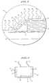
- FIG. 1is a cross-sectional view of a background heat flow sensor as presently used
- FIG. 2is a cross-sectional view of a preferred embodiment of the present invention in use
- FIG. 3is a closeup of the portion of FIG. 2 shown encircled
- FIG. 4is a schematic plan view of a background sensor for measuring heat loss as developed by the inventors of the present invention.
- FIG. 5is a schematic plan view of a first preferred sensor for measuring heat loss of the present invention.
- FIG. 6is a cross-sectional view of a second preferred sensor for measuring heat loss of the present invention.
- FIG. 7shows a background heat flow sensor utilizing thermocouples
- FIGS. 8 ( a ) and 8 ( b )show a further preferred sensor for measuring heat loss of the present invention
- FIG. 9shows a structure of a novel membrane used in a heat flow sensor of the present invention.
- FIG. 10shows the attachment of the sensor of the present invention in a preferred embodiment of the present invention.
- perspirationincludes sensible or insensible fluid loss and is not limited to fluids which include salt, etc. This, however, is not the only application of the present invention.
- Other uses of the present inventioninclude, for example, optimization of evaporative coolers.
- the present inventionmeasures conductive, convective, radiant, and evaporative heat flow using a modified heat flow sensor element.
- FIG. 1is a cross-sectional view of a background heat flow sensor element as typically used.
- the heat flow sensor element 10traps perspiration 17 against the subject's skin 16 . This prevents the perspiration 17 from evaporating and prevents evaporative heat loss from the area of skin 16 covered with the heat flow sensor element 10 . Since the heat flow sensor element 10 is not measuring evaporative heat flow, which is occurring on the surrounding skin 16 , the heat flow measurement is not representative of the heat loss 20 on the surrounding skin 16 . This error will cause the estimated heat loss 21 to be lower than the actual heat loss 20 by an amount equal to the heat loss due to evaporation.
- perspiration 17will accumulate under the sensor 10 and some perspiration 18 will leak out, and collect in the region surrounding the sensor 10 .
- This collection of perspiration 18 around the edge of the heat flow sensor element 10will cause an increased heat loss 22 in the region surrounding the sensor 10 .
- Traditional sensor element 10 designplaces the sensing elements in the center of the sensor element 10 , away from the edges, so that such traditional sensor elements 10 are most sensitive in the center where the sensing elements are. Since such background heat flow sensor elements 10 are most sensitive in the center of the sensor area and least sensitive at the fringe area, the increased heat loss 22 in the area surrounding the sensor 10 will not be detected. Further, increased losses at the edges of the sensor 10 would cause local cooling, thus decreasing convective and radiant heat flow measured by the sensor 10 .
- FIGS. 2 and 3One embodiment of such an improved heat flow sensor, generally, 8 , is depicted in FIGS. 2 and 3. In that heat flow sensor 8 heat flow sensor element 10 is positioned on a surface 16 , such as skin, as will subsequently be described.
- the heat flow sensor 8provides an overlay material 12 which allows the perspiration build-up 18 around the fringe of the heat flow sensor element 10 to migrate through the overlay material 12 as illustrated by the arrows 11 , to the ambient air side 24 of the heat flow sensor 10 .
- This migrationenhances allowing perspiration to evaporate from the outer surface 24 of the heat flow element 10 , which simulates the evaporative heat loss which is occurring on the subject's skin surface 16 .
- the overlay material 12has a perspiration evaporation rate similar to that of the skin of the subject 16 under the same conditions. This evaporation rate typically can vary as much as and is preferably within the range of 20 g/m2 /day to 100 g/m2 /hr.
- the overlay material 12allows moisture to migrate onto the surface of the sensor element 10 , but other techniques could also be used to cause the migration of moisture, such as by utilizing hydrophilic surface treatments or coatings, etching grooves into the sensor surface, etc.
- the overlay material 12should be capable of “imbibing” evaporative fluid, such as perspiration, preferably “wicking” the perspiration from the skin surface 16 to the ambient air side 24 of the heat flow sensor element 10 .
- Overlay materialswhich appear to function best are constructed of leather, synthetic membranes, tight weave fabric, etc., although other materials could be utilized.
- An example of a synthetic membrane suitable as an overlay materialis manufactured by Millipore.
- Other examples of suitable synthetic membranesinclude those sold under the trade names Thermipor, and Versapor.TM. manufactured by Gelman Sciences, Inc., Ann Arbor, Mich.
- overlay material 12In general, the thinner the overlay material 12 is, the better the process works. Additionally, it has been found that overlay materials having 1 - 20 micron openings are particularly well-suited to “wicking” the perspiration build-up 18 from the measured surface 16 to the ambient air side 24 of the heat flow sensor element 10 .
- suitable tight weave materialis Spectra/Mesh, manufactured by Spectrum of Los Angeles, Calif.
- the heat flow sensor 8can include a thermally conductive layer 14 placed across both the ambient air side 24 of the sensor element 10 and a portion of the surrounding skin surface 16 . This creates a substantially uniform heat flow across both the skin surface 16 and the top 24 of the heat flow sensor element 10 so that the top surface 24 of the heat flow sensor element 10 will sense substantially the same heat flow as is occurring across the surrounding skin surface 16 . This helps to correct heat flow variation caused by less perspiration across the center surface compared to the edges, and thus less evaporation, on the top 24 of the heat flow sensor element 10 than on the skin surface 16 .
- the thermally conductive materialis selected from the group consisting of metal foil, including, by way of example but not limitation, copper, aluminum, stainless steel, and gold foils, vacuum deposited metal film, and thermally conductive plastics, and preferably has a thickness ranging from about 3000 .ANG. to 2 mils.
- the heat flow sensor 8contains both an overlay material and a thermally conductive layer, the heat flow sensor 8 could also include the use of either element alone.
- the method of fastening the apparatus to the usershould not inhibit heat flow. If the method of fastening the apparatus to the user traps heat against the skin surface, i.e. it insulates, there is a danger that the artificially increased skin temperature will cause a measurement error by the heat flow sensor.
- the straps used for mounting heat flow sensor 8use an open weave material, preferably having openings of 1 ⁇ 8-1 ⁇ 4 inch and over 95% open area, to fasten the device to the user; however, other materials may also be used.
- multiple heat flow sensors 8each having overlays 12 and/or thermally conductive layers 14 are positioned at various locations on the subject's body, to determine a total heat loss value for the subject.
- a single heat flow sensing apparatus 8is placed at a location on the subject's body that is typical of heat loss for that subject.
- the subject's trunk or extremities near the trunkare usually representative of heat loss.
- typical regionsmay also vary from subject to subject, and may be determined by applying multiple sensing apparatus 8 to the subject, evaluating each sensor individually and identifying the sensor or sensors that most nearly represent the total heat loss for all sensors for that subject. Once a “typical” region for heat loss is identified for that subject, the subject need only use one sensor 8 attached to that typical region.
- the sensing apparatus 8is attached to the wearer with, for example, an elastic armband which may be fabricated of an open weave material that allows the wearer to exercise freely.
- the heat flow informationmay be continuously monitored and recorded by a microcontroller or analog device capable of converting heat flow information into caloric expenditure information, both in terms of rate of caloric expenditure and cumulative caloric expenditure.
- microcontrollersinclude, by way of example, those available from Intel, including the Intel Pentium family.
- Calorie expendituremay be calculated in a number of ways from the measure of heat flow obtained from the methods and apparatus of the present invention.
- a preferred methodis based on the following equation:
- Calorie expenditure (k ⁇ cal)total body surface area( m 2 ) ⁇ fraction of body surface sampled by each sensor (1 for one sensor sensing typical region of heat flow) ⁇ heat flux(k ⁇ cal/ m 2 /min.) ⁇ time of sensing (min.).
- the microcontrolleris preferably programmed to continually monitor, record, and total heat flux for the subject, thereby allowing both an instantaneous rate of calorie expenditure and a total caloric expenditure for the subject to be monitored.
- the thermally conductive layer 14may include center surface area 29 and a fringe region, generally 30 , extending beyond the perimeter of the sensor element 10 .
- This fringe region 30may comprise a series of “fingers” 31 formed in the thermally conductive layer 14 .
- the fringe area 30preferably is located about a substantial portion of the periphery of the heat flow sensor element 10 , but may exclude that portion through which the wire connectors 32 of the heat flow sensor element 10 pass.
- the fingers 31have an open area 33 between adjacent fingers.
- FIGS. 5 and 6 of the present inventionTo further improve the sensing of perspiration by promoting the migration of perspiration from edges of a sensor element into the central active area of the sensor element two novel sensor designs as shown in FIGS. 5 and 6 of the present invention have now been developed by the present inventors.
- FIG. 5shows a first example of a novel sensor design of the present invention.
- element 500indicates the sensor of that embodiment of the present invention, which essentially corresponds to the sensor 10 shown in FIGS. 1-4, i.e., the sensor 500 of FIG. 5 is utilized for the sensor 10 in FIGS. 1-4.
- the same sensor construction as sensor 10 in FIGS. 1-4is utilized except that the sensor 500 of FIG. 5 includes electrode elements 501 , 502 , and 503 on the surface. Electrodes 501 and 502 have a positive electric field applied thereto and electrode 503 has a negative electric field applied thereto. The electrode 503 is located in the center of the sensor 500 between electrodes 501 and 502 , and thus is at the active region of the sensor 500 .
- the sensor 500 of FIG. 5operates under a principle of electroendosmosis in which water, i.e., the perspiration from an evaporative loss, moves in response to an applied electric field from a positive electric field to a negative electric field.
- the perspiration which reaches the end of the sensor 500is migrated by electroendosmosis from the end of the sensor 500 towards the center of the sensor 500 by the electric charge induced by the electrodes 501 , 502 , 503 .
- the perspirationis migrated away from the positive electrodes 501 , 502 , i.e., those electrodes which receive a positive voltage, at the edges of the sensor 500 and towards the negatively biased electrode 503 in the center of the sensor 500 .
- the electrode 503is the central electrode which is at an active region of the sensor, with such a structure of the present invention the perspiration to be sensed is migrated to an appropriate position on the sensor 500 .
- the electrodes 501 , 502 , and 503would typically be provided at a top surface of the sensor 500 to receive the perspiration migrated as shown by arrows 11 in FIG. 3, i.e., the perspiration migrates as shown by arrows 11 in FIG. 3 to the top surface of the sensor 500 and thereby the electrodes 501 , 502 , 503 are preferably provided at the top surface of the sensor 500 .
- FIG. 6shows a second embodiment of an improved sensor design of the present invention operating on the process of electroendosmosis but in a depthwise direction. That is, FIG. 6 shows in cross-sectional form a further sensor structure 600 of a further embodiment of the present invention.
- the sensor structure 600 of FIG. 6is substantially the same as the sensor 10 of FIGS. 1-4 except that electrode elements 601 , 602 , and 603 are provided.
- a positively biased electrode 601is provided at the bottom surface of the sensor 600 , i.e., at a surface which is to contact the skin of the body. Further, other electrodes 602 , 603 having a negative electric field applied thereto are provided at a top surface of the sensor 600 above the electrode 601 . Again operating on the process of electroendosmosis, perspiration against the skin of the body migrates through a depth-wise direction of the sensor 600 from the positive biased electrode 601 to the negative biased electrodes 602 , 603 , and thereby is provided at an appropriate point, at the sensor 600 to accurately reflect evaporative losses. In the embodiment shown in FIG.
- the positively biased electrode 602is positioned in a center of the sensor 600 whereas the negatively biased electrodes 602 , 603 are provided at edges of the sensor 600 . With such a positioning the evaporation can more accurately wick evaporation from the skin surface.
- Utilizing the sensor structures as shown in FIGS. 5 and 6can improve the operation of a sensor in determining evaporative losses.
- the novel sensors 500 and 600 of respective FIGS. 5 and 6operate on the basis of electroendosmosis in which an electrical bias is used to assist in the migration of perspiration to appropriate points on a sensor.
- An alternative approach, however, recognized by the present inventors to allow perspiration to more easily migrate onto an active area of a sensoris to reduce at least one dimension of the sensor, to thereby decrease the distance the perspiration has to migrate.
- the sensor element 10can take the form of a thermocouple utilized to measure heat loss across an interlayer.
- FIG. 7A structure of a background thermocouple sensor is shown in FIG. 7 .
- a background thermocouple sensor 700includes an interlayer 710 across which a difference in temperature is measured.
- thermocouple sensor 700has a structure to measure a temperature difference between a bottom of the interlayer 710 and a top of the interlayer 710 .
- the thermocouple sensor 700 of FIG. 7achieves that operation by forming plural thermocouples 715 at a center point of the interlayer 710 both on the top and the bottom of the interlayer 710 , although only the top thermocouples 715 are shown in FIG. 7 .
- Those thermocouples 715are formed at the junction of first and second thermocouple elements 720 and 725 .
- thermocouple sensor 700has the drawback that the perspiration still has a significant path to migrate.
- thermocouple sensorwhich can reduce the path distance that perspiration must migrate to reach the active thermocouple elements, and which can thereby provide a more accurate measurement of heat flow and evaporation.
- FIGS. 8 ( a ) and 8 ( b )Such a novel thermocouple sensor element of the present invention is shown in FIGS. 8 ( a ) and 8 ( b ).
- FIGS. 8 ( a ) and 8 ( b )show a further construction of a sensor 800 according to the present invention which can be utilized as the sensor element 10 .
- the structure of the heat flow sensor 800 of FIGS. 8 ( a ) and 8 ( b )enhances the migration of perspiration to the active area of the sensor by reducing the distance the perspiration must migrate to reach the active sensing areas of the thermocouples. That is, with the novel sensor structure 800 of FIGS.
- the active thermocouple elements 815 , 817are formed near the edge of the sensor, so that the perspiration only has to migrate a small distance to reach the active thermocouple portions 815 , 817 . Such an operation enhances the heat flow sensing for similar reasons as discussed above.
- the sensor 800also includes, as shown in FIG. 8 ( b ), cover layers 820 for protection of the thermocouples 815 , 817 and for assisting migration of moisture to the thermocouples, particularly when the outer covers 820 are formed of the overlay material 12 as discussed above.
- an overlay material 12can be provided on a sensor element.
- overlay material 12can be formed of a membrane with a novel woven design of two different fibers.
- a further feature of the present inventionis to utilize a membrane as overlay material 12 with a specific construction.
- One feature of the present inventionis to utilize a specific structure of a membrane so that wicking properties of the membrane in one direction can be enhanced without adversely increasing its evaporative surface area.
- Certain threadssuch as under the trade name CoolMax by Dupont, which are Dacron fibers with a convoluted diameter, are engineered to effectively wick perspiration in order to effect greater cooling.
- Such a materialalso would present a significantly higher evaporative surface area than a simple solid thread.
- One feature in the present inventionis to form a membrane 900 by weaving in a relatively small number of threads 910 such as CoolMax with a majority of solid threads 915 of monofilaments of Nylon fiber, for example in a ratio of 1 CoolMax Fiber to 2 Nylon fibers.
- threads 910such as CoolMax
- wicking across the sensorwould be enhanced without resulting in a significant increase in surface area.
- the threadsshould be weaved in one direction, for example the weft.
- the membranewould be positioned to cause the threads to cross over the heat flow sensor as the overlay 12 .
- FIG. 10shows a construction of the sensor of the present invention to improve the ability to relay the information detected by the sensor.
- the inventors of the present inventionhave recognized that it may often be desirable for a user of a heat flow sensor to take the information detected by the heat flow sensor and place it into a device such as a personal computer, a PDA (personal digital assistant), etc. In that way the user could manipulate the data, store the data in a table for comparison purposes, display the data in different graphical forms, etc.
- FIG. 10such a structure is shown in which the heat flow sensors 10 , 500 , 600 , 700 are connected to a PDA.
- PDAOne of the most common PDAs is the Palm Pilot, but of course many PDAs could be utilized including those operating on the Palm Operating System, Microsoft CE, Pocket PC Operating System, and others.
- the heat flow sensors 10 , 500 , 600 , 700can provide the data to the PDA 1000 , or alternatively a PC, etc. by any well known means such as by a line connection, wireless communication, etc.
- That display 1010can be an integral part of the PDA or can be a separate display, such as the separate display of a personal computer.
- the heat flow sensorcommunicates with a data logger/output device, and/or a PC, and/or a PDA, and/or any other type of output device capable of receiving the signal through either radio frequency (RF), infra-red transmission (IR), hard-wired communication, or other means.
- RFradio frequency
- IRinfra-red transmission
- the devicemay also be completely integrated as one unit including both a device to generate and capture a signal, and to then translate and display results, or it may include separate units to perform those functions.
- the measuring deviceincludes a communication device enabling wired or wireless connection between the heat-flow sensor, and/or thermocouple, or thermistor or other heat-flow measuring device for the measurement of calorie expenditures to a data logger, a PC, a PDA, or other output device.
- the PC or PDA or data-loggertranslates the signal from the heat-flow sensor into calorie expenditures via software utilizing stored information. Feedback of this information to the user will help the user to know their caloric expenditure. This information can be useful for fitness monitoring, well-being monitoring, weight management, etc.
- the PC or PDA or data-loggermay also contain stored information about previous calorie expenditures over the previous minute, hour, day, week, month or year or other time interval. This information can be used for various uses including comparisons to previous measurements as well as comparisons to calorie intake. Additionally, the caloric and nutritional content of food can be stored in this database for use in comparing the calorie intake of food with the caloric expenditure of the user. This information is then used to determine level of fitness, well-being, weight management, etc.
Landscapes
- Health & Medical Sciences (AREA)
- Life Sciences & Earth Sciences (AREA)
- Engineering & Computer Science (AREA)
- Physics & Mathematics (AREA)
- Biomedical Technology (AREA)
- Heart & Thoracic Surgery (AREA)
- Veterinary Medicine (AREA)
- Public Health (AREA)
- Biophysics (AREA)
- Pathology (AREA)
- General Health & Medical Sciences (AREA)
- Animal Behavior & Ethology (AREA)
- Medical Informatics (AREA)
- Molecular Biology (AREA)
- Surgery (AREA)
- General Physics & Mathematics (AREA)
- Chemical & Material Sciences (AREA)
- Combustion & Propulsion (AREA)
- Obesity (AREA)
- Measuring And Recording Apparatus For Diagnosis (AREA)
Abstract
Description
Claims (32)
Priority Applications (4)
| Application Number | Priority Date | Filing Date | Title |
|---|---|---|---|
| US09/854,603US6533731B2 (en) | 2001-05-15 | 2001-05-15 | Method and apparatus for measuring heat flow |
| PCT/US2002/011888WO2002091917A1 (en) | 2001-05-15 | 2002-05-15 | Method and apparatus for measuring heat flow |
| JP2002588839AJP4298299B2 (en) | 2001-05-15 | 2002-05-15 | Method and apparatus for measuring heat flow |
| EP02726752AEP1392157A4 (en) | 2001-05-15 | 2002-05-15 | Method and apparatus for measuring heat flow |
Applications Claiming Priority (1)
| Application Number | Priority Date | Filing Date | Title |
|---|---|---|---|
| US09/854,603US6533731B2 (en) | 2001-05-15 | 2001-05-15 | Method and apparatus for measuring heat flow |
Publications (2)
| Publication Number | Publication Date |
|---|---|
| US20020173730A1 US20020173730A1 (en) | 2002-11-21 |
| US6533731B2true US6533731B2 (en) | 2003-03-18 |
Family
ID=25319134
Family Applications (1)
| Application Number | Title | Priority Date | Filing Date |
|---|---|---|---|
| US09/854,603Expired - LifetimeUS6533731B2 (en) | 2001-05-15 | 2001-05-15 | Method and apparatus for measuring heat flow |
Country Status (4)
| Country | Link |
|---|---|
| US (1) | US6533731B2 (en) |
| EP (1) | EP1392157A4 (en) |
| JP (1) | JP4298299B2 (en) |
| WO (1) | WO2002091917A1 (en) |
Cited By (17)
| Publication number | Priority date | Publication date | Assignee | Title |
|---|---|---|---|---|
| US20020191675A1 (en)* | 2001-06-18 | 2002-12-19 | Omron Corporation | Electronic clinical thermometer |
| US20030198276A1 (en)* | 2002-04-19 | 2003-10-23 | Agency For Defense Development | Heat-flux gage, manufacturing method and manufacturing device thereof |
| US20050113650A1 (en)* | 2000-06-16 | 2005-05-26 | Christopher Pacione | System for monitoring and managing body weight and other physiological conditions including iterative and personalized planning, intervention and reporting capability |
| US20050113703A1 (en)* | 2003-09-12 | 2005-05-26 | Jonathan Farringdon | Method and apparatus for measuring heart related parameters |
| US20050259714A1 (en)* | 2004-05-20 | 2005-11-24 | Yuli Lozinski | System for measuring heat flow |
| US20060031102A1 (en)* | 2000-06-16 | 2006-02-09 | Bodymedia, Inc. | System for detecting, monitoring, and reporting an individual's physiological or contextual status |
| US20060122474A1 (en)* | 2000-06-16 | 2006-06-08 | Bodymedia, Inc. | Apparatus for monitoring health, wellness and fitness |
| US20060224051A1 (en)* | 2000-06-16 | 2006-10-05 | Bodymedia, Inc. | Wireless communications device and personal monitor |
| US20060264730A1 (en)* | 2002-08-22 | 2006-11-23 | Bodymedia, Inc. | Apparatus for detecting human physiological and contextual information |
| US20070038038A1 (en)* | 1999-10-18 | 2007-02-15 | Bodymedia, Inc. | Wearable human physiological and environmental data sensors and reporting system therefor |
| US20070100666A1 (en)* | 2002-08-22 | 2007-05-03 | Stivoric John M | Devices and systems for contextual and physiological-based detection, monitoring, reporting, entertainment, and control of other devices |
| US20080167572A1 (en)* | 2002-08-22 | 2008-07-10 | John Stivoric | Systems, methods, and devices to determine and predict physilogical states of individuals and to administer therapy, reports, notifications, and the like therefor |
| US20080319796A1 (en)* | 2007-02-16 | 2008-12-25 | Stivoric John M | Medical applications of lifeotypes |
| US20090177068A1 (en)* | 2002-10-09 | 2009-07-09 | Stivoric John M | Method and apparatus for providing derived glucose information utilizing physiological and/or contextual parameters |
| US20090209828A1 (en)* | 2005-03-09 | 2009-08-20 | Ramil Faritovich Musin | Method and device microcalorimetrically measuring a tissue local metabolism speed, intracellular tissue water content, blood biochemical component concentration and a cardio-vascular system tension |
| US8157731B2 (en) | 2002-10-09 | 2012-04-17 | Bodymedia, Inc. | Method and apparatus for auto journaling of continuous or discrete body states utilizing physiological and/or contextual parameters |
| US9763581B2 (en) | 2003-04-23 | 2017-09-19 | P Tech, Llc | Patient monitoring apparatus and method for orthosis and other devices |
Families Citing this family (24)
| Publication number | Priority date | Publication date | Assignee | Title |
|---|---|---|---|---|
| DE102005004933B3 (en)* | 2005-02-03 | 2006-08-31 | Dräger Safety AG & Co. KGaA | Device for measuring the body temperature of a living being |
| US9123614B2 (en) | 2008-10-07 | 2015-09-01 | Mc10, Inc. | Methods and applications of non-planar imaging arrays |
| US8389862B2 (en) | 2008-10-07 | 2013-03-05 | Mc10, Inc. | Extremely stretchable electronics |
| US8097926B2 (en) | 2008-10-07 | 2012-01-17 | Mc10, Inc. | Systems, methods, and devices having stretchable integrated circuitry for sensing and delivering therapy |
| FR2968532B1 (en) | 2010-12-14 | 2013-04-26 | Commissariat Energie Atomique | DEVICE AND METHOD FOR DETERMINING AN EXCRETION RATE OF A BODILY FLUID BY AN INDIVIDUAL OR ANIMAL |
| US9171794B2 (en) | 2012-10-09 | 2015-10-27 | Mc10, Inc. | Embedding thin chips in polymer |
| WO2014058473A1 (en) | 2012-10-09 | 2014-04-17 | Mc10, Inc. | Conformal electronics integrated with apparel |
| US9706647B2 (en) | 2013-05-14 | 2017-07-11 | Mc10, Inc. | Conformal electronics including nested serpentine interconnects |
| EP3071096A4 (en) | 2013-11-22 | 2017-08-09 | Mc10, Inc. | Conformal sensor systems for sensing and analysis of cardiac activity |
| US10485118B2 (en) | 2014-03-04 | 2019-11-19 | Mc10, Inc. | Multi-part flexible encapsulation housing for electronic devices and methods of making the same |
| USD781270S1 (en) | 2014-10-15 | 2017-03-14 | Mc10, Inc. | Electronic device having antenna |
| JP6497097B2 (en)* | 2015-02-05 | 2019-04-10 | セイコーエプソン株式会社 | Vaporization calorimeter, biological information measuring device, and electronic device |
| WO2016134306A1 (en) | 2015-02-20 | 2016-08-25 | Mc10, Inc. | Automated detection and configuration of wearable devices based on on-body status, location, and/or orientation |
| US10709384B2 (en)* | 2015-08-19 | 2020-07-14 | Mc10, Inc. | Wearable heat flux devices and methods of use |
| EP4079383A3 (en) | 2015-10-01 | 2023-02-22 | Medidata Solutions, Inc. | Method and system for interacting with a virtual environment |
| JP2017067761A (en)* | 2015-10-01 | 2017-04-06 | 株式会社デンソー | Abnormality symptom diagnosis device |
| US10532211B2 (en) | 2015-10-05 | 2020-01-14 | Mc10, Inc. | Method and system for neuromodulation and stimulation |
| US10673280B2 (en) | 2016-02-22 | 2020-06-02 | Mc10, Inc. | System, device, and method for coupled hub and sensor node on-body acquisition of sensor information |
| US10277386B2 (en) | 2016-02-22 | 2019-04-30 | Mc10, Inc. | System, devices, and method for on-body data and power transmission |
| CN109310340A (en) | 2016-04-19 | 2019-02-05 | Mc10股份有限公司 | Method and system for measuring sweat |
| US10447347B2 (en) | 2016-08-12 | 2019-10-15 | Mc10, Inc. | Wireless charger and high speed data off-loader |
| JP6614169B2 (en)* | 2017-01-25 | 2019-12-04 | 株式会社Soken | Physiological calorimeter |
| CN108514405B (en)* | 2018-04-12 | 2021-12-10 | 京东方科技集团股份有限公司 | Body temperature paster and body temperature detecting system |
| DE102019105807A1 (en)* | 2019-03-07 | 2020-09-10 | Rheinisch-Westfälische Technische Hochschule (Rwth) Aachen | Textile with thermocouple |
Citations (7)
| Publication number | Priority date | Publication date | Assignee | Title |
|---|---|---|---|---|
| US4345844A (en)* | 1979-05-09 | 1982-08-24 | Marcel Birukoff | Calorimeter |
| US4762423A (en)* | 1985-03-27 | 1988-08-09 | Walter Basta | Evaporation calorimeter |
| US5040541A (en)* | 1985-04-01 | 1991-08-20 | Thermonetics Corporation | Whole body calorimeter |
| US5205170A (en) | 1991-04-01 | 1993-04-27 | Ford Motor Company | Mass flow sensor |
| US5329812A (en)* | 1991-03-20 | 1994-07-19 | Mitsubishi Denki Kabushiki Kaisha | Thermal flow sensor |
| US5465618A (en)* | 1992-04-30 | 1995-11-14 | Mitsubishi Denki Kabushiki Kaisha | Thermal flow sensor and heat-sensitive resistor therefor |
| US5524618A (en)* | 1993-06-02 | 1996-06-11 | Pottgen; Paul A. | Method and apparatus for measuring heat flow |
Family Cites Families (2)
| Publication number | Priority date | Publication date | Assignee | Title |
|---|---|---|---|---|
| SU718731A1 (en)* | 1977-06-14 | 1980-02-29 | Институт Технической Теплофизики Ан Украинской Сср | Method of manufacturing thermoelectric heat flux sensors |
| US5555565A (en)* | 1995-06-23 | 1996-09-17 | Tanner Lynx Corporation | Thick pile sock with heterogeneous body and foot portions, and sock system therewith |
- 2001
- 2001-05-15USUS09/854,603patent/US6533731B2/ennot_activeExpired - Lifetime
- 2002
- 2002-05-15WOPCT/US2002/011888patent/WO2002091917A1/enactiveApplication Filing
- 2002-05-15EPEP02726752Apatent/EP1392157A4/ennot_activeCeased
- 2002-05-15JPJP2002588839Apatent/JP4298299B2/ennot_activeExpired - Fee Related
Patent Citations (8)
| Publication number | Priority date | Publication date | Assignee | Title |
|---|---|---|---|---|
| US4345844A (en)* | 1979-05-09 | 1982-08-24 | Marcel Birukoff | Calorimeter |
| US4762423A (en)* | 1985-03-27 | 1988-08-09 | Walter Basta | Evaporation calorimeter |
| US5040541A (en)* | 1985-04-01 | 1991-08-20 | Thermonetics Corporation | Whole body calorimeter |
| US5329812A (en)* | 1991-03-20 | 1994-07-19 | Mitsubishi Denki Kabushiki Kaisha | Thermal flow sensor |
| US5205170A (en) | 1991-04-01 | 1993-04-27 | Ford Motor Company | Mass flow sensor |
| US5465618A (en)* | 1992-04-30 | 1995-11-14 | Mitsubishi Denki Kabushiki Kaisha | Thermal flow sensor and heat-sensitive resistor therefor |
| US5524618A (en)* | 1993-06-02 | 1996-06-11 | Pottgen; Paul A. | Method and apparatus for measuring heat flow |
| US5813994A (en)* | 1993-06-02 | 1998-09-29 | Pottgen; Paul A. | Method and apparatus for measuring heat flow |
Cited By (41)
| Publication number | Priority date | Publication date | Assignee | Title |
|---|---|---|---|---|
| US20070038038A1 (en)* | 1999-10-18 | 2007-02-15 | Bodymedia, Inc. | Wearable human physiological and environmental data sensors and reporting system therefor |
| US8403845B2 (en) | 1999-10-18 | 2013-03-26 | Bodymedia, Inc. | Wearable human physiological and environmental data sensors and reporting system therefor |
| US20080183052A1 (en)* | 2000-06-16 | 2008-07-31 | Eric Teller | Multi-sensor system, device, and method for deriving human status information |
| US20060224051A1 (en)* | 2000-06-16 | 2006-10-05 | Bodymedia, Inc. | Wireless communications device and personal monitor |
| US20050113650A1 (en)* | 2000-06-16 | 2005-05-26 | Christopher Pacione | System for monitoring and managing body weight and other physiological conditions including iterative and personalized planning, intervention and reporting capability |
| US8961413B2 (en) | 2000-06-16 | 2015-02-24 | Bodymedia, Inc. | Wireless communications device and personal monitor |
| US8073707B2 (en) | 2000-06-16 | 2011-12-06 | Bodymedia, Inc. | System for detecting, monitoring, and reporting an individual's physiological or contextual status |
| US20060031102A1 (en)* | 2000-06-16 | 2006-02-09 | Bodymedia, Inc. | System for detecting, monitoring, and reporting an individual's physiological or contextual status |
| US20060122474A1 (en)* | 2000-06-16 | 2006-06-08 | Bodymedia, Inc. | Apparatus for monitoring health, wellness and fitness |
| US9033875B2 (en) | 2000-06-16 | 2015-05-19 | Bodymedia, Inc. | Multi-sensor system, device, and method for deriving human status information |
| US8398546B2 (en) | 2000-06-16 | 2013-03-19 | Bodymedia, Inc. | System for monitoring and managing body weight and other physiological conditions including iterative and personalized planning, intervention and reporting capability |
| US20070173705A1 (en)* | 2000-06-16 | 2007-07-26 | Eric Teller | Apparatus for monitoring health, wellness and fitness |
| US7689437B1 (en) | 2000-06-16 | 2010-03-30 | Bodymedia, Inc. | System for monitoring health, wellness and fitness |
| US8961414B2 (en) | 2000-06-16 | 2015-02-24 | Aliphcom | Apparatus for monitoring health, wellness and fitness |
| US20020191675A1 (en)* | 2001-06-18 | 2002-12-19 | Omron Corporation | Electronic clinical thermometer |
| US6886978B2 (en)* | 2001-06-18 | 2005-05-03 | Omron Corporation | Electronic clinical thermometer |
| US6837614B2 (en)* | 2002-04-19 | 2005-01-04 | Agency For Defence Development | Heat-flux gage, manufacturing method and manufacturing device thereof |
| US20030198276A1 (en)* | 2002-04-19 | 2003-10-23 | Agency For Defense Development | Heat-flux gage, manufacturing method and manufacturing device thereof |
| US20060264730A1 (en)* | 2002-08-22 | 2006-11-23 | Bodymedia, Inc. | Apparatus for detecting human physiological and contextual information |
| US20080167572A1 (en)* | 2002-08-22 | 2008-07-10 | John Stivoric | Systems, methods, and devices to determine and predict physilogical states of individuals and to administer therapy, reports, notifications, and the like therefor |
| US9168001B2 (en) | 2002-08-22 | 2015-10-27 | Bodymedia, Inc. | Adhesively mounted apparatus for determining physiological and contextual status |
| US20070100666A1 (en)* | 2002-08-22 | 2007-05-03 | Stivoric John M | Devices and systems for contextual and physiological-based detection, monitoring, reporting, entertainment, and control of other devices |
| US9204806B2 (en)* | 2002-08-22 | 2015-12-08 | Bodymedia, Inc. | Apparatus using temperature data to make predictions about an individual |
| US20090177068A1 (en)* | 2002-10-09 | 2009-07-09 | Stivoric John M | Method and apparatus for providing derived glucose information utilizing physiological and/or contextual parameters |
| US8157731B2 (en) | 2002-10-09 | 2012-04-17 | Bodymedia, Inc. | Method and apparatus for auto journaling of continuous or discrete body states utilizing physiological and/or contextual parameters |
| US9763581B2 (en) | 2003-04-23 | 2017-09-19 | P Tech, Llc | Patient monitoring apparatus and method for orthosis and other devices |
| US7502643B2 (en) | 2003-09-12 | 2009-03-10 | Bodymedia, Inc. | Method and apparatus for measuring heart related parameters |
| US20050113703A1 (en)* | 2003-09-12 | 2005-05-26 | Jonathan Farringdon | Method and apparatus for measuring heart related parameters |
| US8369936B2 (en) | 2003-09-12 | 2013-02-05 | Bodymedia, Inc. | Wearable apparatus for measuring heart-related parameters and deriving human status parameters from sensed physiological and contextual parameters |
| US7232255B2 (en) | 2004-05-20 | 2007-06-19 | Alina Lozinski | System for measuring heat flow |
| US20050259714A1 (en)* | 2004-05-20 | 2005-11-24 | Yuli Lozinski | System for measuring heat flow |
| US20090209828A1 (en)* | 2005-03-09 | 2009-08-20 | Ramil Faritovich Musin | Method and device microcalorimetrically measuring a tissue local metabolism speed, intracellular tissue water content, blood biochemical component concentration and a cardio-vascular system tension |
| US20080320030A1 (en)* | 2007-02-16 | 2008-12-25 | Stivoric John M | Lifeotype markup language |
| US8382590B2 (en) | 2007-02-16 | 2013-02-26 | Bodymedia, Inc. | Entertainment, gaming and interactive spaces based on lifeotypes |
| US8275635B2 (en) | 2007-02-16 | 2012-09-25 | Bodymedia, Inc. | Integration of lifeotypes with devices and systems |
| US20080320029A1 (en)* | 2007-02-16 | 2008-12-25 | Stivoric John M | Lifeotype interfaces |
| US20080319786A1 (en)* | 2007-02-16 | 2008-12-25 | Stivoric John M | Publishing and insurance applications of lifeotypes |
| US20080319855A1 (en)* | 2007-02-16 | 2008-12-25 | Stivoric John M | Advertising and marketing based on lifeotypes |
| US20080319787A1 (en)* | 2007-02-16 | 2008-12-25 | Stivoric John M | Integration of lifeotypes with devices and systems |
| US20080319781A1 (en)* | 2007-02-16 | 2008-12-25 | Stivoric John M | Assessment and grouping applications of lifeotypes |
| US20080319796A1 (en)* | 2007-02-16 | 2008-12-25 | Stivoric John M | Medical applications of lifeotypes |
Also Published As
| Publication number | Publication date |
|---|---|
| EP1392157A4 (en) | 2010-01-06 |
| WO2002091917A1 (en) | 2002-11-21 |
| JP4298299B2 (en) | 2009-07-15 |
| EP1392157A1 (en) | 2004-03-03 |
| JP2004528912A (en) | 2004-09-24 |
| US20020173730A1 (en) | 2002-11-21 |
Similar Documents
| Publication | Publication Date | Title |
|---|---|---|
| US6533731B2 (en) | Method and apparatus for measuring heat flow | |
| US5524618A (en) | Method and apparatus for measuring heat flow | |
| US10709384B2 (en) | Wearable heat flux devices and methods of use | |
| Doherty et al. | Evaluation of the physiological bases of thermal comfort models | |
| Huang et al. | A wearable thermometry for core body temperature measurement and its experimental verification | |
| Hayward et al. | Thermoregulatory heat production in man: prediction equation based on skin and core temperatures | |
| Berglund et al. | Evaporation of sweat from sedentary man in humid environments | |
| US20070295713A1 (en) | System and method for measuring core body temperature | |
| Parsons | Human heat stress | |
| US20220128413A1 (en) | Core body temperature sensor and method for the manufacturing thereof | |
| Uchiyama et al. | Estimation of core temperature based on a human thermal model using a wearable sensor | |
| Barker et al. | Thermal characteristics of clothing ensembles for use in heat stress analysis | |
| Huang et al. | Wearable deep body thermometers and their uses in continuous monitoring for daily healthcare | |
| Pavlinic et al. | Using a mathematical model of human temperature regulation to evaluate the impact of protective clothing on wearer thermal balance | |
| Hamatani et al. | Real-time calibration of a human thermal model with solar radiation using wearable sensors | |
| Namisnak et al. | A Conformable Two-Dimensional Resistance Temperature Detector for Measuring Average Skin Temperature | |
| Kopec | Response of the wet-bulb-globe-thermometer heat stress index to selected land use surfaces | |
| Rescio et al. | Biometric Parameters Assessment for Foot Ulcers Prevention Through Wearable Devices | |
| Yoshida et al. | Evaluation methods of adaptation cities | |
| Finvers et al. | Wireless temporal artery bandage thermometer | |
| JP7593494B2 (en) | Temperature estimation system and temperature estimation method | |
| Hepokoski et al. | Development of an Advanced Clothing Model that Considers Heat and Moisture Transport | |
| Rescio et al. | Smart insole for diabetic foot monitoring | |
| Kirubha et al. | Infrared Thermographic Analysis of Interrelation Between Blood Pressure and Temperature of Forearm for Normal, High and Low BP Subjects | |
| Tamás et al. | The use of wireless data communication and body sensing devices to evaluate occupants’ comfort in buildings |
Legal Events
| Date | Code | Title | Description |
|---|---|---|---|
| AS | Assignment | Owner name:LIFECHEK, LLC, PENNSYLVANIA Free format text:ASSIGNMENT OF ASSIGNORS INTEREST;ASSIGNORS:POTTGEN, PAUL A.;SZUMINSKY, NEIL J.;REEL/FRAME:013317/0745 Effective date:20020225 | |
| REMI | Maintenance fee reminder mailed | ||
| FPAY | Fee payment | Year of fee payment:4 | |
| SULP | Surcharge for late payment | ||
| REMI | Maintenance fee reminder mailed | ||
| LAPS | Lapse for failure to pay maintenance fees | ||
| REIN | Reinstatement after maintenance fee payment confirmed | ||
| FP | Lapsed due to failure to pay maintenance fee | Effective date:20110318 | |
| FEPP | Fee payment procedure | Free format text:PETITION RELATED TO MAINTENANCE FEES FILED (ORIGINAL EVENT CODE: PMFP); ENTITY STATUS OF PATENT OWNER: SMALL ENTITY | |
| FEPP | Fee payment procedure | Free format text:PETITION RELATED TO MAINTENANCE FEES DISMISSED (ORIGINAL EVENT CODE: PMFS); ENTITY STATUS OF PATENT OWNER: SMALL ENTITY | |
| FEPP | Fee payment procedure | Free format text:PETITION RELATED TO MAINTENANCE FEES FILED (ORIGINAL EVENT CODE: PMFP); ENTITY STATUS OF PATENT OWNER: SMALL ENTITY | |
| FPAY | Fee payment | Year of fee payment:8 | |
| SULP | Surcharge for late payment | ||
| PRDP | Patent reinstated due to the acceptance of a late maintenance fee | Effective date:20130531 | |
| STCF | Information on status: patent grant | Free format text:PATENTED CASE | |
| REMI | Maintenance fee reminder mailed | ||
| FEPP | Fee payment procedure | Free format text:PAT HOLDER CLAIMS SMALL ENTITY STATUS, ENTITY STATUS SET TO SMALL (ORIGINAL EVENT CODE: LTOS); ENTITY STATUS OF PATENT OWNER: SMALL ENTITY | |
| FPAY | Fee payment | Year of fee payment:12 | |
| SULP | Surcharge for late payment | Year of fee payment:11 |