US6532956B2 - Parameter variation for proportional assist ventilation or proportional positive airway pressure support devices - Google Patents
Parameter variation for proportional assist ventilation or proportional positive airway pressure support devicesDownload PDFInfo
- Publication number
- US6532956B2 US6532956B2US09/813,189US81318901AUS6532956B2US 6532956 B2US6532956 B2US 6532956B2US 81318901 AUS81318901 AUS 81318901AUS 6532956 B2US6532956 B2US 6532956B2
- Authority
- US
- United States
- Prior art keywords
- patient
- pressure
- flow
- breathing gas
- airway
- Prior art date
- Legal status (The legal status is an assumption and is not a legal conclusion. Google has not performed a legal analysis and makes no representation as to the accuracy of the status listed.)
- Expired - Lifetime
Links
- 238000009423ventilationMethods0.000titleabstractdescription43
- 238000000034methodMethods0.000claimsabstractdescription26
- 230000006870functionEffects0.000claimsdescription72
- 230000029058respiratory gaseous exchangeEffects0.000claimsdescription72
- 238000012545processingMethods0.000claimsdescription2
- 238000002560therapeutic procedureMethods0.000abstractdescription7
- 239000007789gasSubstances0.000description67
- 230000008859changeEffects0.000description14
- 230000003434inspiratory effectEffects0.000description11
- 230000001965increasing effectEffects0.000description10
- 238000004364calculation methodMethods0.000description8
- 238000012544monitoring processMethods0.000description6
- 230000000241respiratory effectEffects0.000description6
- 230000007704transitionEffects0.000description5
- 230000007423decreaseEffects0.000description4
- 230000008569processEffects0.000description4
- 230000003247decreasing effectEffects0.000description3
- 238000010586diagramMethods0.000description3
- MWUXSHHQAYIFBG-UHFFFAOYSA-NNitric oxideChemical compoundO=[N]MWUXSHHQAYIFBG-UHFFFAOYSA-N0.000description2
- QVGXLLKOCUKJST-UHFFFAOYSA-Natomic oxygenChemical compound[O]QVGXLLKOCUKJST-UHFFFAOYSA-N0.000description2
- 238000007796conventional methodMethods0.000description2
- 230000000694effectsEffects0.000description2
- 238000005259measurementMethods0.000description2
- 239000000203mixtureSubstances0.000description2
- 238000012986modificationMethods0.000description2
- 230000004048modificationEffects0.000description2
- 239000001301oxygenSubstances0.000description2
- 229910052760oxygenInorganic materials0.000description2
- 241000894006BacteriaSpecies0.000description1
- 230000001351cycling effectEffects0.000description1
- 230000001419dependent effectEffects0.000description1
- 229940079593drugDrugs0.000description1
- 239000003814drugSubstances0.000description1
- 230000009977dual effectEffects0.000description1
- 230000003028elevating effectEffects0.000description1
- 238000001595flow curveMethods0.000description1
- GWUAFYNDGVNXRS-UHFFFAOYSA-Nhelium;molecular oxygenChemical compound[He].O=OGWUAFYNDGVNXRS-UHFFFAOYSA-N0.000description1
- 238000004519manufacturing processMethods0.000description1
- 244000144985peepSpecies0.000description1
- 230000001225therapeutic effectEffects0.000description1
- 210000003437tracheaAnatomy0.000description1
- 230000000007visual effectEffects0.000description1
Images


Classifications
- A—HUMAN NECESSITIES
- A61—MEDICAL OR VETERINARY SCIENCE; HYGIENE
- A61M—DEVICES FOR INTRODUCING MEDIA INTO, OR ONTO, THE BODY; DEVICES FOR TRANSDUCING BODY MEDIA OR FOR TAKING MEDIA FROM THE BODY; DEVICES FOR PRODUCING OR ENDING SLEEP OR STUPOR
- A61M16/00—Devices for influencing the respiratory system of patients by gas treatment, e.g. ventilators; Tracheal tubes
- A61M16/0057—Pumps therefor
- A61M16/0066—Blowers or centrifugal pumps
- A61M16/0069—Blowers or centrifugal pumps the speed thereof being controlled by respiratory parameters, e.g. by inhalation
- A—HUMAN NECESSITIES
- A61—MEDICAL OR VETERINARY SCIENCE; HYGIENE
- A61M—DEVICES FOR INTRODUCING MEDIA INTO, OR ONTO, THE BODY; DEVICES FOR TRANSDUCING BODY MEDIA OR FOR TAKING MEDIA FROM THE BODY; DEVICES FOR PRODUCING OR ENDING SLEEP OR STUPOR
- A61M16/00—Devices for influencing the respiratory system of patients by gas treatment, e.g. ventilators; Tracheal tubes
- A61M16/021—Devices for influencing the respiratory system of patients by gas treatment, e.g. ventilators; Tracheal tubes operated by electrical means
- A61M16/022—Control means therefor
- A61M16/024—Control means therefor including calculation means, e.g. using a processor
- A—HUMAN NECESSITIES
- A61—MEDICAL OR VETERINARY SCIENCE; HYGIENE
- A61M—DEVICES FOR INTRODUCING MEDIA INTO, OR ONTO, THE BODY; DEVICES FOR TRANSDUCING BODY MEDIA OR FOR TAKING MEDIA FROM THE BODY; DEVICES FOR PRODUCING OR ENDING SLEEP OR STUPOR
- A61M16/00—Devices for influencing the respiratory system of patients by gas treatment, e.g. ventilators; Tracheal tubes
- A61M16/10—Preparation of respiratory gases or vapours
- A61M16/14—Preparation of respiratory gases or vapours by mixing different fluids, one of them being in a liquid phase
- A61M16/16—Devices to humidify the respiration air
- A61M16/161—Devices to humidify the respiration air with means for measuring the humidity
- A—HUMAN NECESSITIES
- A61—MEDICAL OR VETERINARY SCIENCE; HYGIENE
- A61M—DEVICES FOR INTRODUCING MEDIA INTO, OR ONTO, THE BODY; DEVICES FOR TRANSDUCING BODY MEDIA OR FOR TAKING MEDIA FROM THE BODY; DEVICES FOR PRODUCING OR ENDING SLEEP OR STUPOR
- A61M16/00—Devices for influencing the respiratory system of patients by gas treatment, e.g. ventilators; Tracheal tubes
- A61M16/06—Respiratory or anaesthetic masks
- A—HUMAN NECESSITIES
- A61—MEDICAL OR VETERINARY SCIENCE; HYGIENE
- A61M—DEVICES FOR INTRODUCING MEDIA INTO, OR ONTO, THE BODY; DEVICES FOR TRANSDUCING BODY MEDIA OR FOR TAKING MEDIA FROM THE BODY; DEVICES FOR PRODUCING OR ENDING SLEEP OR STUPOR
- A61M16/00—Devices for influencing the respiratory system of patients by gas treatment, e.g. ventilators; Tracheal tubes
- A61M16/10—Preparation of respiratory gases or vapours
- A61M16/1005—Preparation of respiratory gases or vapours with O2 features or with parameter measurement
- A61M16/101—Preparation of respiratory gases or vapours with O2 features or with parameter measurement using an oxygen concentrator
- A—HUMAN NECESSITIES
- A61—MEDICAL OR VETERINARY SCIENCE; HYGIENE
- A61M—DEVICES FOR INTRODUCING MEDIA INTO, OR ONTO, THE BODY; DEVICES FOR TRANSDUCING BODY MEDIA OR FOR TAKING MEDIA FROM THE BODY; DEVICES FOR PRODUCING OR ENDING SLEEP OR STUPOR
- A61M16/00—Devices for influencing the respiratory system of patients by gas treatment, e.g. ventilators; Tracheal tubes
- A61M16/0003—Accessories therefor, e.g. sensors, vibrators, negative pressure
- A61M2016/0015—Accessories therefor, e.g. sensors, vibrators, negative pressure inhalation detectors
- A61M2016/0018—Accessories therefor, e.g. sensors, vibrators, negative pressure inhalation detectors electrical
- A61M2016/0021—Accessories therefor, e.g. sensors, vibrators, negative pressure inhalation detectors electrical with a proportional output signal, e.g. from a thermistor
- A—HUMAN NECESSITIES
- A61—MEDICAL OR VETERINARY SCIENCE; HYGIENE
- A61M—DEVICES FOR INTRODUCING MEDIA INTO, OR ONTO, THE BODY; DEVICES FOR TRANSDUCING BODY MEDIA OR FOR TAKING MEDIA FROM THE BODY; DEVICES FOR PRODUCING OR ENDING SLEEP OR STUPOR
- A61M16/00—Devices for influencing the respiratory system of patients by gas treatment, e.g. ventilators; Tracheal tubes
- A61M16/0003—Accessories therefor, e.g. sensors, vibrators, negative pressure
- A61M2016/0027—Accessories therefor, e.g. sensors, vibrators, negative pressure pressure meter
- A—HUMAN NECESSITIES
- A61—MEDICAL OR VETERINARY SCIENCE; HYGIENE
- A61M—DEVICES FOR INTRODUCING MEDIA INTO, OR ONTO, THE BODY; DEVICES FOR TRANSDUCING BODY MEDIA OR FOR TAKING MEDIA FROM THE BODY; DEVICES FOR PRODUCING OR ENDING SLEEP OR STUPOR
- A61M16/00—Devices for influencing the respiratory system of patients by gas treatment, e.g. ventilators; Tracheal tubes
- A61M16/0003—Accessories therefor, e.g. sensors, vibrators, negative pressure
- A61M2016/003—Accessories therefor, e.g. sensors, vibrators, negative pressure with a flowmeter
- A61M2016/0033—Accessories therefor, e.g. sensors, vibrators, negative pressure with a flowmeter electrical
- A61M2016/0039—Accessories therefor, e.g. sensors, vibrators, negative pressure with a flowmeter electrical in the inspiratory circuit
- A—HUMAN NECESSITIES
- A61—MEDICAL OR VETERINARY SCIENCE; HYGIENE
- A61M—DEVICES FOR INTRODUCING MEDIA INTO, OR ONTO, THE BODY; DEVICES FOR TRANSDUCING BODY MEDIA OR FOR TAKING MEDIA FROM THE BODY; DEVICES FOR PRODUCING OR ENDING SLEEP OR STUPOR
- A61M16/00—Devices for influencing the respiratory system of patients by gas treatment, e.g. ventilators; Tracheal tubes
- A61M16/10—Preparation of respiratory gases or vapours
- A61M16/1005—Preparation of respiratory gases or vapours with O2 features or with parameter measurement
- A61M2016/102—Measuring a parameter of the content of the delivered gas
- A61M2016/103—Measuring a parameter of the content of the delivered gas the CO2 concentration
- A—HUMAN NECESSITIES
- A61—MEDICAL OR VETERINARY SCIENCE; HYGIENE
- A61M—DEVICES FOR INTRODUCING MEDIA INTO, OR ONTO, THE BODY; DEVICES FOR TRANSDUCING BODY MEDIA OR FOR TAKING MEDIA FROM THE BODY; DEVICES FOR PRODUCING OR ENDING SLEEP OR STUPOR
- A61M2205/00—General characteristics of the apparatus
- A61M2205/15—Detection of leaks
- A—HUMAN NECESSITIES
- A61—MEDICAL OR VETERINARY SCIENCE; HYGIENE
- A61M—DEVICES FOR INTRODUCING MEDIA INTO, OR ONTO, THE BODY; DEVICES FOR TRANSDUCING BODY MEDIA OR FOR TAKING MEDIA FROM THE BODY; DEVICES FOR PRODUCING OR ENDING SLEEP OR STUPOR
- A61M2205/00—General characteristics of the apparatus
- A61M2205/50—General characteristics of the apparatus with microprocessors or computers
- A61M2205/502—User interfaces, e.g. screens or keyboards
- A61M2205/505—Touch-screens; Virtual keyboard or keypads; Virtual buttons; Soft keys; Mouse touches
- A—HUMAN NECESSITIES
- A61—MEDICAL OR VETERINARY SCIENCE; HYGIENE
- A61M—DEVICES FOR INTRODUCING MEDIA INTO, OR ONTO, THE BODY; DEVICES FOR TRANSDUCING BODY MEDIA OR FOR TAKING MEDIA FROM THE BODY; DEVICES FOR PRODUCING OR ENDING SLEEP OR STUPOR
- A61M2230/00—Measuring parameters of the user
- A61M2230/40—Respiratory characteristics
- A61M2230/43—Composition of exhalation
- A61M2230/432—Composition of exhalation partial CO2 pressure (P-CO2)
Definitions
- the present inventionpertains to a pressure support apparatus and method for controlling a pressure support therapy administered to a patient, and, in particular, to a controlling a proportional assist ventilation or a proportional positive airway pressure mode of ventilating a patient by varying at least one parameter associated with one of these ventilation techniques according to a parameter variation function.
- the pressure delivered by the ventilator to the patientincreases in direct proportion to patient breathing effort, so that the greater the patient effort, the greater the pressure of breathing delivered by the ventilator. More specifically, the pressure of gas delivered by the ventilator to the patient is determined based on a product of a first gain and a signal indicative of a rate of flow of breathing gas provided to such a patient in combination with a product of a second gain and signal indicative of a volume of breathing gas provided to the patient. This relationship is summarized as follows:
- P patientis the pressure at the patient interface device, such as the patient's nasal mask, nasal/oral mask, nasal cannula, or trachea tube
- FAis a flow assist multiplier, which is a fraction of respiratory resistance
- ⁇ dot over (V) ⁇is the instantaneous flow of gas to the patient
- VAis a volume assist multiplier, which is a fraction of respiratory elastance
- Vis the instantaneous volume of gas delivered to the patient.
- pressure supportis provided to a patient according to the following equation:
- %Setis a common multiplier or scaling factor applied to both FA* ⁇ dot over (V) ⁇ and VA*V
- EPAPis the expiratory positive airway pressure, which is a minimum baseline pressure applied to the patient during the expiratory phase of his or her breathing cycle.
- the caregiversets the following parameters of equations (1) or (2): %Set, FA, VA, and EPAP. This is done either based on data garnered from patient observation and caregiver experience and expertise, data gathered from measurements of various physiological parameters of the patient, such as respiratory elastance and resistance, or based on a predetermined values that are generally believed to be appropriate for a given group of patients.
- %Set%Set
- FArespiratory elastance and resistance
- the caregivermay reduce the %Set level to reduce the assistance to breathing provided by the ventilator. It is also known to set one of more of the parameters, %Set, FA, VA, and EPAP, automatically, to modify these settings automatically, or both.
- P patientis the pressure delivered to the patient interface device
- P baseis the base line pressure (greater than or equal to zero and conceptually equal to EPAP)
- ⁇ dot over (V) ⁇is the instantaneous flow of gas to the patient, which can be measured directly via a flow transducer or estimated from a flow transducer measurement and a leak component determination
- Gainis a constant used to augment the pressure delivered to the patient based on the flow rate.
- P patient(insp)is the pressured delivered to the patient during inhalation
- Gain inspis the constant used during inspiration to boost pressure based on the flow rate
- P patient(exp)is the pressure delivered during exhalation
- Gain expis the constant used during exhalation to reduce pressure based on the flow rate.
- the PPAP parametersi.e., P base , Gain insp , and Gain exp , of the PPAP relation are set by the caregiver and do not change unless altered by the caregiver. For example, the caregiver may deem it appropriate to change the Gain insp or Gain exp to maximize the comfort of the PPAP ventilation provided to the patient. It is also known to automate the process for setting the PPAP parameters automatically, automate the process for modifying these parameters, or to automate both the initial setting and modification of these parameters.
- conventional ventilation techniquesinvolve starting the patient on either pressure support therapy by setting the various parameters and then starting the therapy.
- the patientis left to cope with the relatively sudden change in ventilation assistance once the ventilation assistance begins.
- this transitioncan be relatively large.
- the caregivercan manually adjust the parameters to provide a more comfortable transition for the patient.
- thisrequires the caregiver continually monitor and manually change the ventilator settings, which is time consuming.
- a patient treatment systemthat includes a gas flow generating system, a pressure controller, and a flow and volume sensing system.
- the gas flow generating systemprovides a flow of breathing gas to an airway of a patient.
- the pressure controllercontrols the pressure of breathing gas provided to the patient.
- the sensing systemfor detects the instantaneous flow rate ⁇ dot over (V) ⁇ and instantaneous volume V of breathing gas provided to the patient.
- the patient treatment systemalso includes a control unit that controls the operation of the pressure controller based on the output from the sensing system. More specifically, the control unit causes the pressure of breathing gas to be provided to the patient in accordance with the following relation:
- P patientis the pressure at an airway of the patient
- % Setis a multiplier
- FAis a flow assist multiplier
- VAis a volume assist multiplier
- EPAPis an expiratory positive airway pressure
- R 1 (t), R 2 (t), R 3 (t), R 4 (t), and R 5 (t)are time-based parameter variation functions.
- at least one of the parameter variation functions R 1 (t), R 2 (t), R 3 (t), R 4 (t), and R 5 (t)is a function other than a unity function or one (1).
- control unitcauses the flow of breathing gas to be provided to the patient at a pressure in accordance with a following relation at least during a portion of the breathing cycle:
- P patientis the pressure at an airway of such a patient
- Gainis a constant
- P baseis a base-line pressure
- R 1 (t), R 2 (t), and R 3 (t)are time-based parameter variation functions, where at least one parameter variation function R 1 (t), R 2 (t), and R 3 (t) is a function other than a unity function or one (1).
- the present inventionalso contemplates providing different PPAP equations, with the potential for different parameter variation functions, during the inspiratory and expiratory phases of the breathing cycle, as well as providing PPAP in combination with providing a continuous positive airway pressure (CPAP) or a bi-level positive airway pressure.
- CPAPcontinuous positive airway pressure
- bi-level positive airway pressureCPAP
- This objectis achieved by providing a method that includes providing a flow of breathing gas to an airway of a patient, detecting an instantaneous flow rate ⁇ dot over (V) ⁇ and an instantaneous volume V of the flow of breathing gas, and controlling a pressure of breathing gas provided to an airway of the patient in accordance with the following relation:
- R 1 (t), R 2 (t), R 3 (t), R 4 (t), and R 5 (t)are time-based parameter variation functions, where at least one parameter variation function R 1 (t), R 2 (t), R 3 (t), R 4 (t), and R 5 (t) is a function other than a unity function or one (1).
- Still further embodiments of the present inventioncontemplate using a similar method to provide the PPAP mode of ventilation to the patient, with the parameter variation functions being provided for one or more terms in the PPAP pressure calculation or calculations, depending on whether different PPAP equations are used for inspiration and expiration.
- the present inventionenables one or more of the parameters in the PAV or PPAP pressure calculation equation to change over time, rather than subject the patient to an abrupt ventilation change.
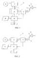
- FIG. 1is a schematic diagram of a first embodiment of pressure support system capable of administering a pressure support treatment according to the principles of the present invention
- FIG. 2is a schematic diagram of a second embodiment of pressure support system capable of administering a pressure support treatment according to the principles of the present invention
- FIG. 3is a pressure curve illustrating an example of how the PAV pressure provided to the patient can vary over time according to the principles of the present invention
- FIG. 4is a diagram of an exemplary embodiment of a time-based parameter variation function
- FIGS. 5A-5B, 6 A- 6 B, and 7 A- 7 Billustrate exemplary output flow and PPAP pressure curves that can be provided by the patient treatment systems of FIGS. 1 or 2 and further show how the PPAP pressure provided to the patient can vary over time according to the parameter variation functions of the present invention.
- FIG. 1schematically illustrates an exemplary first embodiment of a patient treatment system 30 capable of providing and automatically controlling the pressure of breathing gas delivered to a patient using a PAV or PPAP mode of ventilation according to the principles of the present invention.
- Patient treatment system 30includes a pressure generator 32 that receives a supply of breathing from a breathing gas source 34 and elevates the pressure of that gas for delivery to the airway of a patient.
- Pressure generator 32is any device, such as a blower, piston, or bellows that is capable of elevating the pressure of the received breathing gas for delivery to a patient.
- the present inventionalso contemplates that the pressure generator can be defined by a canister or tank of pressurized gas, with the pressure delivered to the patient being controlled by a pressure regulator.
- pressure generatoris a blower that is driven at a constant speed during the course of the pressure support treatment to produce a constant pressure or flow rate at its output 33 .
- breathing gas source 34is any supply of breathing gas, such as ambient atmosphere, a tank of pressurized gas, and an oxygen concentrator.
- the breathing gas for delivery to the patientcan be any gas, such as air or an oxygen mixture, e.g., heliox, or a mixture of a breathing gas and a medication, which can be in gaseous form, such as nitric oxide, or nebulized.
- the elevated pressure flow of breathing gas from pressure generator 32is delivered to a control valve 36 downstream of the pressure generator.
- Control valve 36either alone or in combination with pressure generator 32 , controls the final pressure or flow of gas 35 exiting the pressure/flow generating system, which, in this embodiment includes pressure generator 32 and control valve 36 .
- a suitable pressure/flow controllerincludes at least one valve, such as sleeve or poppet valve, that exhausts gas from the patient circuit as a method of controlling the pressure in the patient circuit.
- pressure generator 32is a blower that operates at all times at only one speed
- control valve 36alone controls the final pressure and flow rate for the breathing gas 35 delivered to the patient.
- the present inventionalso contemplates controlling the operating speed of pressure generator 32 in combination with control valve 36 to control the final pressure and flow rate for the breathing gas delivered to the patient.
- a pressure or flow rate close to the desired pressure or flow ratecan be set by establishing an appropriate operating speed for pressure generator 32 (macro control). Fine tuning (micro control) of the pressure or flow rate can then be provided by control valve 36 so that the two, operating together, determine the final pressure for the breathing gas delivered to the patient.
- the flow of breathing gas output 35 from control valve 36is delivered to a sensor 38 to determine the instantaneous volume V of gas delivered to the patient, the instantaneous flow rate ⁇ dot over (V) ⁇ of such gas to the patient, or both.
- Sensor 38is any device suitable for measuring these parameters, such as a spirometer, pneumotach, variable orifice transducer, or other conventional flow transducer.
- sensor 38is provided at a location relatively distant from patient interface device.
- the present inventioncontemplates locating sensor 38 at any location along patient circuit 40 as well as at patient interface 42 .
- U.S. Pat. No. 6,017,315 to Starr et al.the contents of which are incorporated herein by reference, teaches a quantitative flow member that is located at the patient interface.
- the flow of breathing gasis carried to the, patient via a patient circuit 40 , which is typically a single flexible conduit that carries the flow of breathing gas to a patient interface device 42 .
- Patient interface device 42is any appliance, either invasive or non-invasive, such as a nasal mask, nasal/oral mask, total face mask, nasal cannula, endotracheal tube, or tracheal tube, suitable for communicating a supply of breathing gas to the airway of a patient.
- the patient interface device 42 and/or patient circuit 40includes a suitable exhaust port 44 for exhausting gas from these components to ambient atmosphere.
- Exhaust port 44is preferably a passive exhaust port in the form of a continuously open port that imposes a flow restriction on the exhaust gas to permit control of the pressure of gas within patient interface device 42 . It is to be understood, however, that exhaust port 42 can be an active exhaust port that assumes different configurations to control the exhaust rate. Examples of suitable exhaust ports are taught, for example, in U.S. Pat. Nos. 5,685,296 and 5,937,855 both to Zdrojkowski et al.
- the output of sensor 38is provided to a control unit 46 for processing, if needed, to determine the instantaneous volume V of gas delivered to the patient, the instantaneous flow rate ⁇ dot over (V) ⁇ of such gas to the patient, or both.
- the instantaneous volumeis determined by integrating the measured flow rate. Because the flow sensor is located relatively far from the patient interface in the illustrated embodiment, in order to determine the actual flow rate of gas to the patient or the actuation flow rate of gas from the patient, which is considered a negative flow, control unit 46 receives the output from sensor 38 as an estimated flow and processes this estimated flow information, for example, by performing leak estimation, to determine the actual flow at the patient's airway, as is known to those skilled in the art.
- An input/output device 48provides data and commands to control unit 46 and outputs, in human perceivable form, any information of interest.
- Input/output device 48is any device suitable to provide information and/or commands to control unit 46 via a hardwire or wireless connection and to present information to a user in a human perceivable format.
- Examples of a suitable input/output deviceincludes a keypad, keyboard, touch pad, mouse, visual display (e.g., LCD or LED screen), microphone, speaker, switches, button, dials, lamps, or any other devices that allow a user to input information to and receive information from the treatment system.
- the patient circuitcan be a two-limb circuit, which is common in conventional ventilators.
- the first limblike patient circuit 40 , delivers breathing gas to the patient, except that it lacks an exhaust port. Instead, the second limb carries the exhaust gases from the patient to ambient atmosphere.
- an active exhaust port in the second limb under the control of a controller 46provides the desired level of positive end expiratory pressure PEEP to the patient.
- patient circuit 40 and related componentscan include other conventional devices, such as a humidifier, heater, bacteria filter, temperature sensor, pressure sensor, flow sensor, humidity sensor, and a gas sensor, e.g., a capnometer, that filter, measure, monitor, and analyze the flow of gas to or from the patient.
- Control unit 46controls the actuation of control valve 36 , thereby controlling the pressure of the breathing gas delivered to the patient.
- the pressure of the breathing gasis provided to the patient according to the PAV or PPAP modes of ventilation discussed above.
- control unit 46is suitably programmed with the necessary algorithm or algorithms for calculating the pressure to be applied to the patient according to these modes of ventilation.
- the control unitincludes a memory 50 that stores the programming necessary to perform both PAV and PPAP ventilation, depending on which mode of ventilation is selected by the caregiver using input/output device 48 .
- memory 50is also capable of storing data regarding the operation of the patient treatment system, input commands, alarm thresholds, as well as any other information pertinent to the operation of the patient treatment system, such as measured values of patient flow, volume, pressure, device usage, operating temperatures, and motor speed.
- patient treatment system 52controls the pressure of breathing gas delivered to the patient based only on the output of a pressure generator 54 . That is, controller 46 controls the pressure of breathing gas delivered to the patient by controlling only the motor speed of pressure generator 54 , which is preferably a blower.
- controller 46controls the pressure of breathing gas delivered to the patient by controlling only the motor speed of pressure generator 54 , which is preferably a blower.
- the present inventioncontemplates providing, if necessary, ancillary feedback systems, such a pressure monitor in patient circuit 40 , motor speed monitor, or pressure generator output monitor that provides feedback data to control unit 46 for controlling the operation of pressure generator 54 .
- control unit 46causes the flow of breathing gas to be provided to the patient at a pressure in accordance with the following relation:
- R 1 (t), R 2 (t), R 3 (t), R 4 (t), and R 5 (t)are time-based parameter variation functions used to control or change the effective values of % Set, FA, VA, EPAP, or combinations thereof.
- at least one parameter variation function R 1 (t), R 2 (t), R 3 (t), R 4 (t), and R 5 (t)is a function other than a unity function or one (1).
- the present inventionprovides a high degree of flexibility for varying the parameters associated with the PAV equation without requiring constant monitoring and manual adjustment by the supervising caregiver. This allows for a very smooth transition into and out of PAV, while minimizing the amount of supervision, monitoring and adjusting required of the caregiver.
- R 2 ( t )Min ⁇ 1.0, 0.1 *t +0.2 per second ⁇
- R 1 ( t ), R 3 ( t ), R 4 ( t ), and R 5 ( t )1(unity function).
- the other parameter variation functions R 2 (t), R 3 (t), and R 4 (t)are set to 1 or unity and, thus, do not affect the PAV equation.
- % Setis set to 80%
- FIG. 4illustrates an exemplary embodiment of a function 72 for parameter variation function R 2 (t) that is believed to be useful in weaning a patient off of the PAV mode of ventilation.
- the values of a 0 and a 1are scaling constants, which, for this example, have a range of zero (0) to one (1), respectively.
- the weaning activitybeing at time to, where R 2 (t) decreases linearly from a, to a value of a 0 at time t 1 .
- R 2 (t)is held at a 0 a period until time t 2 , where it increases linearly to a 1 again.
- time periods t 0 -t 1 , t 1 -t 2 , and t 2 -t 3 in this weaning cyclecan be varied.
- a similar processcan be repeated, beginning at t 4 , to repeat the above-described weaning exercise, where during time period t 1 -t 2 the patient receives substantially no assistance other than EPAP pressure to allow the patient to be weaned off of the ventilator support.
- the time periodscan change over time, for example, the time periods t 1 -t 2 where the patient receives substantially no assistance can increase as the number of weaning cycles increase.
- a PPAP mode of pressure support ventilationis administered to the patient and controlled according to one or more parameter variation functions.
- control unit 46causes the flow of breathing gas to be delivered to the patient at a pressure in accordance with the following relation:
- P patientis the pressure at an airway of the patient
- Gainis a constant
- P baseis a base-line pressure (which can be set to zero)
- R 1 (t), R 2 (t), and R 3 (t)are time-based parameter variation functions.
- at least one of the parameter variation functions R 1 (t), R 2 (t), and R 3 (t)is a function other than a unity function.
- control unit 46controls the pressure of breathing gas delivered to the patient in accordance with the relation of equation (7) during patient inspiration or during an inspiratory cycle of the pressure support system, and in accordance with a following relation during patient exhalation or during an expiratory cycle of the pressure support system:
- R 4 (t), R 5 (t), and R 6 (t)are time-based parameter variation functions. At least one parameter variation function R 4 (t), R 5 (t), and R 6 (t) is a function other than a unity function.
- P base in equation (8)can be the same or different from P base in equation (7), and either or both can be set to zero depending on the desired operating characteristics of the PPAP system.
- the present inventioncontemplates using the following PPAP relations to set the pressure delivered to the patient:
- P patient(insp)is the PPAP relation used during inspiration or during an inspiratory cycle of the pressure support system
- P patient(exp)is the PPAP relation used during expiration or during an expiratory cycle of the pressure support system.
- Determining when the patient is in the inspiratory and expiratory phasesis accomplished using any conventional technique, such as by monitoring the gas flow or pressure at the patient's airway or monitoring the expansion of the patient's chest.
- triggering and cycling the pressure support system between the inspiratory and expiratory operating cycles, so that the appropriate PPAP relation is used in each cycleis also accomplished by any conventional technique, such as by monitoring the sign (positive or negative) of the flow of gas at the patient's airway, monitoring the shape of a signal corresponding to such flow, or by comparing flow signal to another signal, such as a threshold valve.
- FIGS. 5A and 5Billustrate a flow curve 74 and pressure curves 76 that can be provided by the above-described device shown in FIGS. 1 and 2 as the Gain insp and Gain exp are adjusted according to the parameter variation functions.
- Pressure curve 78illustrates Gain insp set to a first predetermined level.
- pressure curve 86illustrates Gain exp , set to a first predetermined level
- pressure curves 88 , 90 and 92illustrate how the inspiratory portion of the pressure curve changes as a result of linearly increasing Gain exp over successive time increments.
- base pressure P base 94can be increased or decreased, as indicated by arrow A, in addition to or in place of the changes in Gain insp and Gain exp , over successive respiratory cycles.
- Additional embodiments for providing PPAP to a patientinclude providing PPAP in combination with providing continuous positive airway pressure (CPAP) or in combination with bi-level pressure support, where a higher pressure is applied to the patient during inspiration than during expiration, so that a portion of the pressure profile is provided to the patient in accordance with a PPAP technique and another portion of the pressure profile is provided in accordance with a CPAP or bi-level pressure support technique.
- controller 46includes the necessary circuits and/or programming to effect the bi-level pressure control, including, for example, breathing cycle triggering and leak compensation/estimation.
- FIGS. 6A and 6Bare exemplary flow and pressure curves, respectively, showing an example of the use of PPAP control, which is provided in accordance with equation (7), in conjunction with CPAP 96 .
- Pressure curve 100illustrates Gain exp set to a first predetermined level
- pressure curves 102 and 104illustrate how the expiratory portion of the pressure curve can be changed as a result of linearly increasing Gain exp over successive time increments by, for example, by setting R 5 (t) to a linearly increasing function.
- CPAP level 96can be increased or decreased, as indicated by arrow B, over successive time increments in addition to or in place of the changes in Gain insp and Gain exp by providing a parameter variation function associated with the CPAP pressure level.
- FIGS. 7A and 7Bare flow and pressure curves, respectively, showing an example of the use of PPAP control in combination with bi-level pressure control.
- an inspiratory positive airway pressure (IPAP) 106is delivered during inspiration, and an EPAP 108 is delivered during expiration.
- PPAP controlis only used during the expiratory phase. It can be appreciated, however, that PPAP control can also be used only during the inspiratory phase or during both inspiratory and expiratory phases of the breathing cycle.
- pressure curves 110results in a decrease in pressure of gas administered to the patient, as illustrated by pressure curves 110 , during the expiratory phase.
- Pressure curve 112illustrates Gain exp set to a first predetermined level
- pressure curves 114 and 116illustrate how the expiratory portion of the pressure curve changes as a result of increasing Gain exp over successive time increments by providing, for example, a linearly increasing parameter variation function R 5 (t) associated with the Gain exp .
- IPAP level 106 and EPAP level 108can be increased or decreased, as indicated by arrows C and D, respectively, over successive respiratory cycles in addition to or in place of the changes in Gain insp and Gain exp .
- Dashed lines 118 and 120illustrate how the pressure curve would look during inspiration if PPAP control is used in combination with IPAP during the inspiratory phase.
- Gain insp in pressure curve 120is greater than Gain insp , in pressure curve 118 .
- PPAPin conjunction with a predetermined pressure profile so that a portion of the pressure output follows a preset pressure profile.
- the PPAP portion of the pressure outputwhich is provided in accordance with equation (7) or in accordance with equations (9) and (10), can be controlled according to one or more parameter variation functions as discussed above.
- a parameter variation function associated with the terms or group of terms in the PAV or PPAP equationsprovides a high degree of flexibility in transitioning between various pressure outputs, for example, upon start-up or termination of the PAV or PPAP therapy.
- present inventioncontemplates a potentially infinite variety of shapes, contours, and variations for the parameter variation functions R 1 (t), R 2 (t), R 3 (t), R 4 (t), R 5 (t), and R 6 (t) used in equations (6)-(10).
- one or more of the parameter variation functionscan be expressed as a linear ramp, trapezoid, triangle, square wave, sinusoidal, exponential, or other function.
- the parameter variation functioncan be determined from a polynomial equation or from a graphically entered functions, such as that shown in FIG. 3 .
- the various parameter variations functionscan be related to or dependent upon one another or completely independent of one another.
Landscapes
- Health & Medical Sciences (AREA)
- Emergency Medicine (AREA)
- Pulmonology (AREA)
- Engineering & Computer Science (AREA)
- Anesthesiology (AREA)
- Biomedical Technology (AREA)
- Heart & Thoracic Surgery (AREA)
- Hematology (AREA)
- Life Sciences & Earth Sciences (AREA)
- Animal Behavior & Ethology (AREA)
- General Health & Medical Sciences (AREA)
- Public Health (AREA)
- Veterinary Medicine (AREA)
- Measurement Of The Respiration, Hearing Ability, Form, And Blood Characteristics Of Living Organisms (AREA)
- Orthopedics, Nursing, And Contraception (AREA)
Abstract
Description

Claims (10)
Priority Applications (3)
| Application Number | Priority Date | Filing Date | Title |
|---|---|---|---|
| US09/813,189US6532956B2 (en) | 2000-03-30 | 2001-03-20 | Parameter variation for proportional assist ventilation or proportional positive airway pressure support devices |
| AU2001247663AAU2001247663A1 (en) | 2000-03-30 | 2001-03-22 | Parameter variation for proportional assist ventilation or proportional positive airway pressure support devices |
| PCT/US2001/009108WO2001074430A1 (en) | 2000-03-30 | 2001-03-22 | Parameter variation for proportional assist ventilation or proportional positive airway pressure support devices |
Applications Claiming Priority (2)
| Application Number | Priority Date | Filing Date | Title |
|---|---|---|---|
| US19320000P | 2000-03-30 | 2000-03-30 | |
| US09/813,189US6532956B2 (en) | 2000-03-30 | 2001-03-20 | Parameter variation for proportional assist ventilation or proportional positive airway pressure support devices |
Publications (2)
| Publication Number | Publication Date |
|---|---|
| US20010035186A1 US20010035186A1 (en) | 2001-11-01 |
| US6532956B2true US6532956B2 (en) | 2003-03-18 |
Family
ID=26888770
Family Applications (1)
| Application Number | Title | Priority Date | Filing Date |
|---|---|---|---|
| US09/813,189Expired - LifetimeUS6532956B2 (en) | 2000-03-30 | 2001-03-20 | Parameter variation for proportional assist ventilation or proportional positive airway pressure support devices |
Country Status (3)
| Country | Link |
|---|---|
| US (1) | US6532956B2 (en) |
| AU (1) | AU2001247663A1 (en) |
| WO (1) | WO2001074430A1 (en) |
Cited By (52)
| Publication number | Priority date | Publication date | Assignee | Title |
|---|---|---|---|---|
| US20020185127A1 (en)* | 1995-08-17 | 2002-12-12 | Melker Richard J. | Hybrid microprocessor controlled ventilator unit |
| US20030192544A1 (en)* | 2000-03-03 | 2003-10-16 | Michael Berthon-Jones | Adjustment of ventilator pressure-time profile to balance comfort and effectiveness |
| US20040234610A1 (en)* | 2001-12-05 | 2004-11-25 | Hall Jesse B. | Medical device and method for inhalation of aerosolized drug with heliox |
| US20050011523A1 (en)* | 2003-07-18 | 2005-01-20 | Acoba, Llc | Method and system of Individually controlling airway pressure of a patient's nares |
| US20060005834A1 (en)* | 2004-07-07 | 2006-01-12 | Acoba, Llc | Method and system of providing therapeutic gas to a patient to prevent breathing airway collapse |
| US7044129B1 (en)* | 2003-09-03 | 2006-05-16 | Ric Investments, Llc. | Pressure support system and method |
| US20060118118A1 (en)* | 2003-10-29 | 2006-06-08 | Smaldone Gerald C | Drug delivery systems |
| US20060174885A1 (en)* | 2005-02-08 | 2006-08-10 | Acoba, Llc | Method and related system to control applied pressure in CPAP systems |
| US20060191535A1 (en)* | 2005-02-25 | 2006-08-31 | The Nemours Foundation | Treatment of decompression sickness with inhaled nitric oxide gas |
| US20070017518A1 (en)* | 2003-06-20 | 2007-01-25 | Farrugia Steven P | Method and apparatus for improving the comfort of cpap |
| US20080078389A1 (en)* | 2006-09-29 | 2008-04-03 | Yang Xiao | Heliox delivery system and method with positive pressure support |
| US20080078385A1 (en)* | 2006-09-29 | 2008-04-03 | Yang Xiao | System and method for delivery of medication via inhalation |
| WO2008077003A1 (en)* | 2006-12-19 | 2008-06-26 | Acoba, L.L.C. | Single blower positive airway pressure device and related method |
| US20090013999A1 (en)* | 2004-09-03 | 2009-01-15 | David John Bassin | Adjustment of target ventilation in a servoventilator |
| US20090078258A1 (en)* | 2007-09-21 | 2009-03-26 | Bowman Bruce R | Pressure regulation methods for positive pressure respiratory therapy |
| US20090078255A1 (en)* | 2007-09-21 | 2009-03-26 | Bowman Bruce R | Methods for pressure regulation in positive pressure respiratory therapy |
| WO2011089491A1 (en) | 2010-01-22 | 2011-07-28 | Koninklijke Philips Electronics N.V. | Automatically controlled ventilation system |
| US8251876B2 (en) | 2008-04-22 | 2012-08-28 | Hill-Rom Services, Inc. | Breathing exercise apparatus |
| US8485183B2 (en) | 2008-06-06 | 2013-07-16 | Covidien Lp | Systems and methods for triggering and cycling a ventilator based on reconstructed patient effort signal |
| US8714154B2 (en) | 2011-03-30 | 2014-05-06 | Covidien Lp | Systems and methods for automatic adjustment of ventilator settings |
| US8776792B2 (en) | 2011-04-29 | 2014-07-15 | Covidien Lp | Methods and systems for volume-targeted minimum pressure-control ventilation |
| US8783250B2 (en) | 2011-02-27 | 2014-07-22 | Covidien Lp | Methods and systems for transitory ventilation support |
| US8950398B2 (en) | 2008-09-30 | 2015-02-10 | Covidien Lp | Supplemental gas safety system for a breathing assistance system |
| US9180271B2 (en) | 2012-03-05 | 2015-11-10 | Hill-Rom Services Pte. Ltd. | Respiratory therapy device having standard and oscillatory PEP with nebulizer |
| US9358355B2 (en) | 2013-03-11 | 2016-06-07 | Covidien Lp | Methods and systems for managing a patient move |
| US9375542B2 (en) | 2012-11-08 | 2016-06-28 | Covidien Lp | Systems and methods for monitoring, managing, and/or preventing fatigue during ventilation |
| US9808591B2 (en) | 2014-08-15 | 2017-11-07 | Covidien Lp | Methods and systems for breath delivery synchronization |
| US9950129B2 (en) | 2014-10-27 | 2018-04-24 | Covidien Lp | Ventilation triggering using change-point detection |
| US9956371B2 (en) | 2015-03-24 | 2018-05-01 | Ventec Life Systems, Inc. | Ventilator with integrated cough-assist |
| US9993604B2 (en) | 2012-04-27 | 2018-06-12 | Covidien Lp | Methods and systems for an optimized proportional assist ventilation |
| US10286176B2 (en) | 2017-02-27 | 2019-05-14 | Third Pole, Inc. | Systems and methods for generating nitric oxide |
| US10328228B2 (en) | 2017-02-27 | 2019-06-25 | Third Pole, Inc. | Systems and methods for ambulatory generation of nitric oxide |
| US10362967B2 (en) | 2012-07-09 | 2019-07-30 | Covidien Lp | Systems and methods for missed breath detection and indication |
| US10668239B2 (en) | 2017-11-14 | 2020-06-02 | Covidien Lp | Systems and methods for drive pressure spontaneous ventilation |
| US10773049B2 (en) | 2016-06-21 | 2020-09-15 | Ventec Life Systems, Inc. | Cough-assist systems with humidifier bypass |
| US10905837B2 (en) | 2015-04-02 | 2021-02-02 | Hill-Rom Services Pte. Ltd. | Respiratory therapy cycle control and feedback |
| US11045620B2 (en) | 2019-05-15 | 2021-06-29 | Third Pole, Inc. | Electrodes for nitric oxide generation |
| US11191915B2 (en) | 2018-05-13 | 2021-12-07 | Ventec Life Systems, Inc. | Portable medical ventilator system using portable oxygen concentrators |
| US11247015B2 (en) | 2015-03-24 | 2022-02-15 | Ventec Life Systems, Inc. | Ventilator with integrated oxygen production |
| US11446460B1 (en) | 2021-10-08 | 2022-09-20 | Dechoker LLC | Pressure regulated airway assist device |
| US11479464B2 (en) | 2019-05-15 | 2022-10-25 | Third Pole, Inc. | Systems and methods for generating nitric oxide |
| US11478594B2 (en) | 2018-05-14 | 2022-10-25 | Covidien Lp | Systems and methods for respiratory effort detection utilizing signal distortion |
| US11517691B2 (en) | 2018-09-07 | 2022-12-06 | Covidien Lp | Methods and systems for high pressure controlled ventilation |
| US11691879B2 (en) | 2020-01-11 | 2023-07-04 | Third Pole, Inc. | Systems and methods for nitric oxide generation with humidity control |
| US11701462B2 (en) | 2016-07-15 | 2023-07-18 | Dechoker LLC | Airway assist device |
| US11752287B2 (en) | 2018-10-03 | 2023-09-12 | Covidien Lp | Systems and methods for automatic cycling or cycling detection |
| US11827989B2 (en) | 2020-06-18 | 2023-11-28 | Third Pole, Inc. | Systems and methods for preventing and treating infections with nitric oxide |
| US11833309B2 (en) | 2017-02-27 | 2023-12-05 | Third Pole, Inc. | Systems and methods for generating nitric oxide |
| US11975139B2 (en) | 2021-09-23 | 2024-05-07 | Third Pole, Inc. | Systems and methods for delivering nitric oxide |
| US12017035B2 (en) | 2022-08-30 | 2024-06-25 | Dechoker LLC | Keyed interlocking airway assist device |
| USD1057936S1 (en) | 2020-06-08 | 2025-01-14 | Dechoker LLC | Airway assist device |
| US12440634B2 (en) | 2021-12-21 | 2025-10-14 | Ventec Life Systems, Inc. | Ventilator systems with integrated oxygen delivery, and associated devices and methods |
Families Citing this family (61)
| Publication number | Priority date | Publication date | Assignee | Title |
|---|---|---|---|---|
| US6932084B2 (en) | 1994-06-03 | 2005-08-23 | Ric Investments, Inc. | Method and apparatus for providing positive airway pressure to a patient |
| NZ524990A (en) | 2000-09-28 | 2005-02-25 | Invacare Corp | Carbon dioxide-based BI-level CPAP control |
| IL145461A (en)* | 2001-09-16 | 2006-09-05 | Alyn Woldenberg Family Hospita | Inexsufflator |
| SE0203430D0 (en) | 2002-11-20 | 2002-11-20 | Siemens Elema Ab | Anesthesia apparatus |
| WO2004080516A1 (en)* | 2003-03-14 | 2004-09-23 | Yrt Limited | Improved synchrony between end of ventilator cycles and end of patient efforts during assisted ventilation |
| US7588033B2 (en) | 2003-06-18 | 2009-09-15 | Breathe Technologies, Inc. | Methods, systems and devices for improving ventilation in a lung area |
| US7152598B2 (en) | 2003-06-23 | 2006-12-26 | Invacare Corporation | System and method for providing a breathing gas |
| US7621270B2 (en) | 2003-06-23 | 2009-11-24 | Invacare Corp. | System and method for providing a breathing gas |
| CN1905917B (en) | 2003-08-18 | 2011-08-03 | 门罗生命公司 | Method and device for non-invasive ventilation with nasal interface |
| EP2394687B1 (en) | 2003-11-26 | 2020-07-22 | ResMed Pty Ltd | Apparatus for the systemic control of ventilatory support in the presence of respiratory insufficiency |
| DE102004014538A1 (en)* | 2004-03-23 | 2005-10-13 | Seleon Gmbh | Method for controlling a BiLevel device and BiLevel device |
| WO2006043278A1 (en)* | 2004-10-20 | 2006-04-27 | Deepbreeze Ltd. | Method and system for managing mechanical respiratory ventilation |
| DE102005010488A1 (en)* | 2005-03-04 | 2006-09-07 | Map Medizin-Technologie Gmbh | Apparatus for administering a breathing gas and method for adjusting at least temporarily alternating breathing gas pressures |
| JP2009508645A (en) | 2005-09-20 | 2009-03-05 | ルッツ フレイテッグ, | System, method and apparatus for assisting patient breathing |
| JP2009509610A (en)* | 2005-09-26 | 2009-03-12 | イノヴェント メディカル ソルーションズ,インク. | Forced inspiration exhalation device with ventilator |
| US20070199566A1 (en)* | 2006-02-02 | 2007-08-30 | Be Eri Eliezer | Respiratory apparatus |
| US20080035146A1 (en)* | 2006-05-05 | 2008-02-14 | Jerry Crabb | Methods, systems and computer products for filling lungs |
| JP5191005B2 (en) | 2006-05-18 | 2013-04-24 | ブリーズ テクノロジーズ, インコーポレイテッド | Method and device for tracheostomy |
| EP2068992B1 (en) | 2006-08-03 | 2016-10-05 | Breathe Technologies, Inc. | Devices for minimally invasive respiratory support |
| US8881724B2 (en)* | 2006-10-19 | 2014-11-11 | The General Electric Company | Device and method for graphical mechanical ventilator setup and control |
| US20080202517A1 (en)* | 2007-02-23 | 2008-08-28 | General Electric Company | Setting madatory mechanical ventilation parameters based on patient physiology |
| US20080230061A1 (en)* | 2007-03-23 | 2008-09-25 | General Electric Company | Setting expiratory time in mandatory mechanical ventilation based on a deviation from a stable condition of end tidal gas concentrations |
| US20080230060A1 (en)* | 2007-03-23 | 2008-09-25 | General Electric Company | Setting inspiratory time in mandatory mechanical ventilation based on patient physiology, such as when tidal volume is inspired |
| US20080230064A1 (en)* | 2007-03-23 | 2008-09-25 | General Electric Company | Setting inspiratory time in mandatory mechanical ventilation based on patient physiology, such as when forced inhalation flow ceases |
| US20080230063A1 (en)* | 2007-03-23 | 2008-09-25 | General Electric Company | Setting inspiratory time in mandatory mechanical ventilation based on patient physiology, such as forced inhalation time |
| US8276585B2 (en)* | 2007-04-10 | 2012-10-02 | Resmed Limited | Systems and methods for visualizing pressures and pressure responses to sleep-related triggering events |
| WO2008144589A1 (en) | 2007-05-18 | 2008-11-27 | Breathe Technologies, Inc. | Methods and devices for sensing respiration and providing ventilation therapy |
| CA2696773A1 (en) | 2007-08-23 | 2009-02-26 | Invacare Corporation | Method and apparatus for adjusting desired pressure in positive airway pressure devices |
| EP2203206A4 (en) | 2007-09-26 | 2017-12-06 | Breathe Technologies, Inc. | Methods and devices for treating sleep apnea |
| EP2200686A4 (en) | 2007-09-26 | 2017-11-01 | Breathe Technologies, Inc. | Methods and devices for providing inspiratory and expiratory flow relief during ventilation therapy |
| US8272380B2 (en)* | 2008-03-31 | 2012-09-25 | Nellcor Puritan Bennett, Llc | Leak-compensated pressure triggering in medical ventilators |
| US10207069B2 (en) | 2008-03-31 | 2019-02-19 | Covidien Lp | System and method for determining ventilator leakage during stable periods within a breath |
| WO2009129506A1 (en) | 2008-04-18 | 2009-10-22 | Breathe Technologies, Inc. | Methods and devices for sensing respiration and controlling ventilator functions |
| US8776793B2 (en) | 2008-04-18 | 2014-07-15 | Breathe Technologies, Inc. | Methods and devices for sensing respiration and controlling ventilator functions |
| US8701657B2 (en)* | 2008-08-21 | 2014-04-22 | Geno Llc | Systems for generating nitric oxide |
| CN102196837B (en) | 2008-08-22 | 2015-09-09 | 呼吸科技公司 | Methods and devices for providing mechanical ventilation utilizing an open airway interface |
| US10252020B2 (en) | 2008-10-01 | 2019-04-09 | Breathe Technologies, Inc. | Ventilator with biofeedback monitoring and control for improving patient activity and health |
| US9132250B2 (en) | 2009-09-03 | 2015-09-15 | Breathe Technologies, Inc. | Methods, systems and devices for non-invasive ventilation including a non-sealing ventilation interface with an entrainment port and/or pressure feature |
| US9962512B2 (en) | 2009-04-02 | 2018-05-08 | Breathe Technologies, Inc. | Methods, systems and devices for non-invasive ventilation including a non-sealing ventilation interface with a free space nozzle feature |
| CN111420208B (en) | 2009-04-02 | 2023-07-04 | 呼吸科技公司 | Methods, systems and devices for non-invasive open ventilation using a gas delivery nozzle within an outer tube |
| TW201039872A (en)* | 2009-05-01 | 2010-11-16 | Top Vision Medical Equipment Consultant Co Ltd | Gas delivery mask with features of detection and adjustment of temperature and humidity |
| WO2011029074A1 (en) | 2009-09-03 | 2011-03-10 | Breathe Technologies, Inc. | Methods, systems and devices for non-invasive ventilation including a non-sealing ventilation interface with an entrainment port and/or pressure feature |
| DE102010010248A1 (en)* | 2010-03-03 | 2011-09-08 | Forschungszentrum Borstel Leibniz-Zentrum Für Medizin Und Biowissenschaften | Ventilation method and ventilator |
| US8555880B2 (en)* | 2010-07-28 | 2013-10-15 | Devilbiss Healthcare, Llc | Variable transition pressure profiles for a bi-level breathing therapy machine |
| CA2807416C (en) | 2010-08-16 | 2019-02-19 | Breathe Technologies, Inc. | Methods, systems and devices using lox to provide ventilatory support |
| MX342694B (en)* | 2010-09-15 | 2016-10-10 | Allied Healthcare Prod | Ventilation system. |
| CA2811423C (en) | 2010-09-30 | 2019-03-12 | Breathe Technologies, Inc. | Methods, systems and devices for humidifying a respiratory tract |
| US8695594B2 (en) | 2010-12-06 | 2014-04-15 | General Electric Company | System and method of automated lung recruitment maneuvers |
| US9155853B2 (en)* | 2011-08-31 | 2015-10-13 | General Electric Company | Systems and methods of adjusting ventilator modes and settings visually via a touchscreen |
| CN107308530A (en)* | 2012-05-02 | 2017-11-03 | 瑞思迈有限公司 | The equipment adjusted for pressure therapy |
| US9027552B2 (en) | 2012-07-31 | 2015-05-12 | Covidien Lp | Ventilator-initiated prompt or setting regarding detection of asynchrony during ventilation |
| US9675771B2 (en) | 2013-10-18 | 2017-06-13 | Covidien Lp | Methods and systems for leak estimation |
| EP4321198A3 (en) | 2015-03-20 | 2024-03-27 | ResMed Pty Ltd | Methods and apparatus for ventilatory treatment of respiratory disorders |
| CN104874070B (en)* | 2015-06-01 | 2017-10-24 | 苏州凯迪泰医学科技有限公司 | The medical breathing machine of transformation noninvasive positive pressure ventilation method and application this method |
| US10792449B2 (en) | 2017-10-03 | 2020-10-06 | Breathe Technologies, Inc. | Patient interface with integrated jet pump |
| DE102018008620A1 (en)* | 2017-11-07 | 2019-05-09 | Löwenstein Medical Technology S.A. | Apparatus for ventilation taking into account the influences of a tube |
| JP6988917B2 (en)* | 2017-12-20 | 2022-01-05 | 株式会社村田製作所 | CPAP device |
| SG11202007526TA (en)* | 2018-03-30 | 2020-10-29 | Murata Manufacturing Co | Cpap apparatus |
| CN113631210A (en)* | 2019-02-22 | 2021-11-09 | 斐雪派克医疗保健有限公司 | Adjustable Expiratory Release in Respiratory Therapy |
| DE102020002278A1 (en)* | 2019-04-24 | 2020-10-29 | Löwenstein Medical Technology S.A. | Breathing gas supply system and procedure |
| US11324954B2 (en) | 2019-06-28 | 2022-05-10 | Covidien Lp | Achieving smooth breathing by modified bilateral phrenic nerve pacing |
Citations (16)
| Publication number | Priority date | Publication date | Assignee | Title |
|---|---|---|---|---|
| US5044362A (en) | 1987-02-21 | 1991-09-03 | University Of Manitoba | Lung ventilator device |
| US5535738A (en) | 1994-06-03 | 1996-07-16 | Respironics, Inc. | Method and apparatus for providing proportional positive airway pressure to treat sleep disordered breathing |
| US5694923A (en)* | 1996-08-30 | 1997-12-09 | Respironics, Inc. | Pressure control in a blower-based ventilator |
| US5735267A (en)* | 1996-03-29 | 1998-04-07 | Ohmeda Inc. | Adaptive control system for a medical ventilator |
| US5794615A (en) | 1994-06-03 | 1998-08-18 | Respironics, Inc. | Method and apparatus for providing proportional positive airway pressure to treat congestive heart failure |
| US5868133A (en)* | 1994-10-14 | 1999-02-09 | Bird Products Corporation | Portable drag compressor powered mechanical ventilator |
| US5884622A (en) | 1996-12-20 | 1999-03-23 | University Of Manitoba | Automatic determination of passive elastic and resistive properties of the respiratory system during assisted mechanical ventilation |
| US6000397A (en)* | 1996-07-29 | 1999-12-14 | Siemens Elema Ab | Method and device for detecting a variation in a flowing medium |
| US6024089A (en)* | 1997-03-14 | 2000-02-15 | Nelcor Puritan Bennett Incorporated | System and method for setting and displaying ventilator alarms |
| US6041780A (en)* | 1995-06-07 | 2000-03-28 | Richard; Ron F. | Pressure control for constant minute volume |
| US6105575A (en)* | 1994-06-03 | 2000-08-22 | Respironics, Inc. | Method and apparatus for providing positive airway pressure to a patient |
| US6152129A (en)* | 1996-08-14 | 2000-11-28 | Resmed Limited | Determination of leak and respiratory airflow |
| US6257234B1 (en)* | 1998-08-21 | 2001-07-10 | Respironics, Inc. | Apparatus and method for determining respiratory mechanics of a patient and for controlling a ventilator based thereon |
| US6302851B1 (en)* | 1997-11-13 | 2001-10-16 | Siemens-Elema Ab | Method and apparatus for determining a pulmonary function parameter for gas exchange |
| US6302105B1 (en)* | 1998-03-17 | 2001-10-16 | Resmed Limited | Apparatus for supplying breathable gas |
| US6345619B1 (en)* | 1998-05-25 | 2002-02-12 | Resmed, Limited | Control of the administration of continuous positive airway pressure treatment |
- 2001
- 2001-03-20USUS09/813,189patent/US6532956B2/ennot_activeExpired - Lifetime
- 2001-03-22WOPCT/US2001/009108patent/WO2001074430A1/enactiveApplication Filing
- 2001-03-22AUAU2001247663Apatent/AU2001247663A1/ennot_activeAbandoned
Patent Citations (18)
| Publication number | Priority date | Publication date | Assignee | Title |
|---|---|---|---|---|
| US5044362A (en) | 1987-02-21 | 1991-09-03 | University Of Manitoba | Lung ventilator device |
| US5107830A (en) | 1987-02-21 | 1992-04-28 | University Of Manitoba | Lung ventilator device |
| US5535738A (en) | 1994-06-03 | 1996-07-16 | Respironics, Inc. | Method and apparatus for providing proportional positive airway pressure to treat sleep disordered breathing |
| US6105575A (en)* | 1994-06-03 | 2000-08-22 | Respironics, Inc. | Method and apparatus for providing positive airway pressure to a patient |
| US5794615A (en) | 1994-06-03 | 1998-08-18 | Respironics, Inc. | Method and apparatus for providing proportional positive airway pressure to treat congestive heart failure |
| US5868133A (en)* | 1994-10-14 | 1999-02-09 | Bird Products Corporation | Portable drag compressor powered mechanical ventilator |
| US6041780A (en)* | 1995-06-07 | 2000-03-28 | Richard; Ron F. | Pressure control for constant minute volume |
| US5735267A (en)* | 1996-03-29 | 1998-04-07 | Ohmeda Inc. | Adaptive control system for a medical ventilator |
| US6000397A (en)* | 1996-07-29 | 1999-12-14 | Siemens Elema Ab | Method and device for detecting a variation in a flowing medium |
| US6152129A (en)* | 1996-08-14 | 2000-11-28 | Resmed Limited | Determination of leak and respiratory airflow |
| US5694923A (en)* | 1996-08-30 | 1997-12-09 | Respironics, Inc. | Pressure control in a blower-based ventilator |
| US5884622A (en) | 1996-12-20 | 1999-03-23 | University Of Manitoba | Automatic determination of passive elastic and resistive properties of the respiratory system during assisted mechanical ventilation |
| US6024089A (en)* | 1997-03-14 | 2000-02-15 | Nelcor Puritan Bennett Incorporated | System and method for setting and displaying ventilator alarms |
| US6360745B1 (en)* | 1997-03-14 | 2002-03-26 | Nellcor Puritan Bennett Incorporated | System and method for controlling the start up of a patient ventilator |
| US6302851B1 (en)* | 1997-11-13 | 2001-10-16 | Siemens-Elema Ab | Method and apparatus for determining a pulmonary function parameter for gas exchange |
| US6302105B1 (en)* | 1998-03-17 | 2001-10-16 | Resmed Limited | Apparatus for supplying breathable gas |
| US6345619B1 (en)* | 1998-05-25 | 2002-02-12 | Resmed, Limited | Control of the administration of continuous positive airway pressure treatment |
| US6257234B1 (en)* | 1998-08-21 | 2001-07-10 | Respironics, Inc. | Apparatus and method for determining respiratory mechanics of a patient and for controlling a ventilator based thereon |
Cited By (113)
| Publication number | Priority date | Publication date | Assignee | Title |
|---|---|---|---|---|
| US7156095B2 (en)* | 1995-08-17 | 2007-01-02 | University Of Florida Research Foundation, Inc. | Hybrid microprocessor controlled ventilator unit |
| US20020185127A1 (en)* | 1995-08-17 | 2002-12-12 | Melker Richard J. | Hybrid microprocessor controlled ventilator unit |
| US20030192544A1 (en)* | 2000-03-03 | 2003-10-16 | Michael Berthon-Jones | Adjustment of ventilator pressure-time profile to balance comfort and effectiveness |
| US6755193B2 (en)* | 2000-03-03 | 2004-06-29 | Resmed Limited | Adjustment of ventilator pressure-time profile to balance comfort and effectiveness |
| US20040206355A1 (en)* | 2000-03-03 | 2004-10-21 | Michael Berthon-Jones | Adjustment of ventilator pressure-time profile to balance comfort and effectiveness |
| US8122885B2 (en) | 2000-03-03 | 2012-02-28 | Resmed Limited | Adjustment of ventilator pressure-time profile to balance comfort and effectiveness |
| US7367337B2 (en) | 2000-03-03 | 2008-05-06 | Resmed Limited | Adjustment of ventilator pressure-time profile to balance comfort and effectiveness |
| US20040234610A1 (en)* | 2001-12-05 | 2004-11-25 | Hall Jesse B. | Medical device and method for inhalation of aerosolized drug with heliox |
| US10293127B2 (en) | 2003-06-20 | 2019-05-21 | Resmed Limited | Method and apparatus for improving the comfort of CPAP |
| US8899232B2 (en)* | 2003-06-20 | 2014-12-02 | Resmed Limited | Method and apparatus for improving the comfort of CPAP |
| US20070017518A1 (en)* | 2003-06-20 | 2007-01-25 | Farrugia Steven P | Method and apparatus for improving the comfort of cpap |
| WO2005009501A3 (en)* | 2003-07-18 | 2006-01-19 | Acoba Llc | Method and system of individually controlling airway pressure of a patient’s nares |
| US7114497B2 (en)* | 2003-07-18 | 2006-10-03 | Acoba, Llc | Method and system of individually controlling airway pressure of a patient's nares |
| US20050011523A1 (en)* | 2003-07-18 | 2005-01-20 | Acoba, Llc | Method and system of Individually controlling airway pressure of a patient's nares |
| US7044129B1 (en)* | 2003-09-03 | 2006-05-16 | Ric Investments, Llc. | Pressure support system and method |
| US8567398B2 (en) | 2003-09-03 | 2013-10-29 | Ric Investments, Llc | Pressure support system and method |
| US20060130835A1 (en)* | 2003-09-03 | 2006-06-22 | Ric Investments, Llc | Pressure support system and method |
| US20060118118A1 (en)* | 2003-10-29 | 2006-06-08 | Smaldone Gerald C | Drug delivery systems |
| US20060005834A1 (en)* | 2004-07-07 | 2006-01-12 | Acoba, Llc | Method and system of providing therapeutic gas to a patient to prevent breathing airway collapse |
| US10688263B2 (en) | 2004-09-03 | 2020-06-23 | ResMed Pty Ltd | Adjustment of target ventilation in a servoventilator |
| US20090013999A1 (en)* | 2004-09-03 | 2009-01-15 | David John Bassin | Adjustment of target ventilation in a servoventilator |
| EP1789120A4 (en)* | 2004-09-03 | 2009-10-28 | Resmed Ltd | Adjustment of target ventilation in a servoventilator |
| US9205210B2 (en)* | 2004-09-03 | 2015-12-08 | Resmed Limited | Adjustment of target ventilation in a servoventilator |
| US20060174885A1 (en)* | 2005-02-08 | 2006-08-10 | Acoba, Llc | Method and related system to control applied pressure in CPAP systems |
| US20060191535A1 (en)* | 2005-02-25 | 2006-08-31 | The Nemours Foundation | Treatment of decompression sickness with inhaled nitric oxide gas |
| US20080078385A1 (en)* | 2006-09-29 | 2008-04-03 | Yang Xiao | System and method for delivery of medication via inhalation |
| US20080078389A1 (en)* | 2006-09-29 | 2008-04-03 | Yang Xiao | Heliox delivery system and method with positive pressure support |
| WO2008077003A1 (en)* | 2006-12-19 | 2008-06-26 | Acoba, L.L.C. | Single blower positive airway pressure device and related method |
| US20090078258A1 (en)* | 2007-09-21 | 2009-03-26 | Bowman Bruce R | Pressure regulation methods for positive pressure respiratory therapy |
| US20090078255A1 (en)* | 2007-09-21 | 2009-03-26 | Bowman Bruce R | Methods for pressure regulation in positive pressure respiratory therapy |
| US8251876B2 (en) | 2008-04-22 | 2012-08-28 | Hill-Rom Services, Inc. | Breathing exercise apparatus |
| US8485185B2 (en) | 2008-06-06 | 2013-07-16 | Covidien Lp | Systems and methods for ventilation in proportion to patient effort |
| US8485183B2 (en) | 2008-06-06 | 2013-07-16 | Covidien Lp | Systems and methods for triggering and cycling a ventilator based on reconstructed patient effort signal |
| US9925345B2 (en) | 2008-06-06 | 2018-03-27 | Covidien Lp | Systems and methods for determining patient effort and/or respiratory parameters in a ventilation system |
| US8826907B2 (en) | 2008-06-06 | 2014-09-09 | Covidien Lp | Systems and methods for determining patient effort and/or respiratory parameters in a ventilation system |
| US8485184B2 (en) | 2008-06-06 | 2013-07-16 | Covidien Lp | Systems and methods for monitoring and displaying respiratory information |
| US10828437B2 (en) | 2008-06-06 | 2020-11-10 | Covidien Lp | Systems and methods for triggering and cycling a ventilator based on reconstructed patient effort signal |
| US9114220B2 (en) | 2008-06-06 | 2015-08-25 | Covidien Lp | Systems and methods for triggering and cycling a ventilator based on reconstructed patient effort signal |
| US9126001B2 (en) | 2008-06-06 | 2015-09-08 | Covidien Lp | Systems and methods for ventilation in proportion to patient effort |
| US9956363B2 (en) | 2008-06-06 | 2018-05-01 | Covidien Lp | Systems and methods for triggering and cycling a ventilator based on reconstructed patient effort signal |
| US8950398B2 (en) | 2008-09-30 | 2015-02-10 | Covidien Lp | Supplemental gas safety system for a breathing assistance system |
| WO2011089491A1 (en) | 2010-01-22 | 2011-07-28 | Koninklijke Philips Electronics N.V. | Automatically controlled ventilation system |
| US8783250B2 (en) | 2011-02-27 | 2014-07-22 | Covidien Lp | Methods and systems for transitory ventilation support |
| US8714154B2 (en) | 2011-03-30 | 2014-05-06 | Covidien Lp | Systems and methods for automatic adjustment of ventilator settings |
| US8776792B2 (en) | 2011-04-29 | 2014-07-15 | Covidien Lp | Methods and systems for volume-targeted minimum pressure-control ventilation |
| US9180271B2 (en) | 2012-03-05 | 2015-11-10 | Hill-Rom Services Pte. Ltd. | Respiratory therapy device having standard and oscillatory PEP with nebulizer |
| US10806879B2 (en) | 2012-04-27 | 2020-10-20 | Covidien Lp | Methods and systems for an optimized proportional assist ventilation |
| US9993604B2 (en) | 2012-04-27 | 2018-06-12 | Covidien Lp | Methods and systems for an optimized proportional assist ventilation |
| US10362967B2 (en) | 2012-07-09 | 2019-07-30 | Covidien Lp | Systems and methods for missed breath detection and indication |
| US11642042B2 (en) | 2012-07-09 | 2023-05-09 | Covidien Lp | Systems and methods for missed breath detection and indication |
| US9375542B2 (en) | 2012-11-08 | 2016-06-28 | Covidien Lp | Systems and methods for monitoring, managing, and/or preventing fatigue during ventilation |
| US11229759B2 (en) | 2012-11-08 | 2022-01-25 | Covidien Lp | Systems and methods for monitoring, managing, and preventing fatigue during ventilation |
| US10543326B2 (en) | 2012-11-08 | 2020-01-28 | Covidien Lp | Systems and methods for monitoring, managing, and preventing fatigue during ventilation |
| US11559641B2 (en) | 2013-03-11 | 2023-01-24 | Covidien Lp | Methods and systems for managing a patient move |
| US9358355B2 (en) | 2013-03-11 | 2016-06-07 | Covidien Lp | Methods and systems for managing a patient move |
| US10639441B2 (en) | 2013-03-11 | 2020-05-05 | Covidien Lp | Methods and systems for managing a patient move |
| US9808591B2 (en) | 2014-08-15 | 2017-11-07 | Covidien Lp | Methods and systems for breath delivery synchronization |
| US10864336B2 (en) | 2014-08-15 | 2020-12-15 | Covidien Lp | Methods and systems for breath delivery synchronization |
| US10940281B2 (en) | 2014-10-27 | 2021-03-09 | Covidien Lp | Ventilation triggering |
| US11712174B2 (en) | 2014-10-27 | 2023-08-01 | Covidien Lp | Ventilation triggering |
| US9950129B2 (en) | 2014-10-27 | 2018-04-24 | Covidien Lp | Ventilation triggering using change-point detection |
| US10518059B2 (en) | 2015-03-24 | 2019-12-31 | Ventec Life Systems, Inc. | Passive leak valve |
| US11185655B2 (en) | 2015-03-24 | 2021-11-30 | Ventec Life Systems, Inc. | Passive leak valve |
| US9956371B2 (en) | 2015-03-24 | 2018-05-01 | Ventec Life Systems, Inc. | Ventilator with integrated cough-assist |
| US10576237B2 (en) | 2015-03-24 | 2020-03-03 | Ventec Life Systems, Inc. | Active exhalation valve |
| US10046134B2 (en) | 2015-03-24 | 2018-08-14 | Ventec Life Systems, Inc. | Pressure swing adsorption oxygen generator |
| US10758699B2 (en) | 2015-03-24 | 2020-09-01 | Ventec Life Systems, Inc. | Secretion trap |
| US10105509B2 (en) | 2015-03-24 | 2018-10-23 | Ventec Life Systems, Inc. | Active exhalation valve |
| US11992619B2 (en) | 2015-03-24 | 2024-05-28 | Ventec Life Systems, Inc. | Ventilator with integrated cough-assist |
| US11344692B2 (en) | 2015-03-24 | 2022-05-31 | Ventec Life Systems, Inc. | Respiratory therapy systems and methods |
| US10315002B2 (en) | 2015-03-24 | 2019-06-11 | Ventec Life Systems, Inc. | Ventilator with integrated oxygen production |
| US11291791B2 (en) | 2015-03-24 | 2022-04-05 | Ventee Life Systems, Inc. | Ventilator with integrated cough-assist |
| US11247015B2 (en) | 2015-03-24 | 2022-02-15 | Ventec Life Systems, Inc. | Ventilator with integrated oxygen production |
| US10245406B2 (en) | 2015-03-24 | 2019-04-02 | Ventec Life Systems, Inc. | Ventilator with integrated oxygen production |
| US10905837B2 (en) | 2015-04-02 | 2021-02-02 | Hill-Rom Services Pte. Ltd. | Respiratory therapy cycle control and feedback |
| US11992611B2 (en) | 2015-04-02 | 2024-05-28 | Hill-Rom Services Pte. Ltd. | Respiratory therapy apparatus control |
| US10905836B2 (en) | 2015-04-02 | 2021-02-02 | Hill-Rom Services Pte. Ltd. | Manifold for respiratory device |
| US12246135B2 (en) | 2016-06-21 | 2025-03-11 | Ventec Life Systems, Inc. | Cough-assist systems with humidifier bypass |
| US11679229B2 (en) | 2016-06-21 | 2023-06-20 | Ventec Life Systems, Inc. | Cough-assist systems with humidifier bypass |
| US10773049B2 (en) | 2016-06-21 | 2020-09-15 | Ventec Life Systems, Inc. | Cough-assist systems with humidifier bypass |
| US11701462B2 (en) | 2016-07-15 | 2023-07-18 | Dechoker LLC | Airway assist device |
| US10695523B2 (en) | 2017-02-27 | 2020-06-30 | Third Pole, Inc. | Systems and methods for generating nitric oxide |
| US11554240B2 (en) | 2017-02-27 | 2023-01-17 | Third Pole, Inc. | Systems and methods for ambulatory generation of nitric oxide |
| US11376390B2 (en) | 2017-02-27 | 2022-07-05 | Third Pole, Inc. | Systems and methods for generating nitric oxide |
| US11911566B2 (en) | 2017-02-27 | 2024-02-27 | Third Pole, Inc. | Systems and methods for ambulatory generation of nitric oxide |
| US11833309B2 (en) | 2017-02-27 | 2023-12-05 | Third Pole, Inc. | Systems and methods for generating nitric oxide |
| US10532176B2 (en) | 2017-02-27 | 2020-01-14 | Third Pole, Inc. | Systems and methods for generating nitric oxide |
| US10576239B2 (en) | 2017-02-27 | 2020-03-03 | Third Pole, Inc. | System and methods for ambulatory generation of nitric oxide |
| US10946163B2 (en) | 2017-02-27 | 2021-03-16 | Third Pole, Inc. | Systems and methods for generating nitric oxide |
| US11524134B2 (en) | 2017-02-27 | 2022-12-13 | Third Pole, Inc. | Systems and methods for ambulatory generation of nitric oxide |
| US10328228B2 (en) | 2017-02-27 | 2019-06-25 | Third Pole, Inc. | Systems and methods for ambulatory generation of nitric oxide |
| US10286176B2 (en) | 2017-02-27 | 2019-05-14 | Third Pole, Inc. | Systems and methods for generating nitric oxide |
| US11033705B2 (en) | 2017-02-27 | 2021-06-15 | Third Pole, Inc. | Systems and methods for ambulatory generation of nitric oxide |
| US11559643B2 (en) | 2017-11-14 | 2023-01-24 | Covidien Lp | Systems and methods for ventilation of patients |
| US10668239B2 (en) | 2017-11-14 | 2020-06-02 | Covidien Lp | Systems and methods for drive pressure spontaneous ventilation |
| US11931509B2 (en) | 2017-11-14 | 2024-03-19 | Covidien Lp | Systems and methods for drive pressure spontaneous ventilation |
| US11191915B2 (en) | 2018-05-13 | 2021-12-07 | Ventec Life Systems, Inc. | Portable medical ventilator system using portable oxygen concentrators |
| US12434026B2 (en) | 2018-05-13 | 2025-10-07 | Ventec Life Systems, Inc. | Portable medical ventilator system using portable oxygen concentrators |
| US12370333B2 (en) | 2018-05-13 | 2025-07-29 | Ventec Life Systems, Inc. | Portable medical ventilator system using portable oxygen concentrators |
| US11478594B2 (en) | 2018-05-14 | 2022-10-25 | Covidien Lp | Systems and methods for respiratory effort detection utilizing signal distortion |
| US11517691B2 (en) | 2018-09-07 | 2022-12-06 | Covidien Lp | Methods and systems for high pressure controlled ventilation |
| US11752287B2 (en) | 2018-10-03 | 2023-09-12 | Covidien Lp | Systems and methods for automatic cycling or cycling detection |
| US11479464B2 (en) | 2019-05-15 | 2022-10-25 | Third Pole, Inc. | Systems and methods for generating nitric oxide |
| US11478601B2 (en) | 2019-05-15 | 2022-10-25 | Third Pole, Inc. | Electrodes for nitric oxide generation |
| US11045620B2 (en) | 2019-05-15 | 2021-06-29 | Third Pole, Inc. | Electrodes for nitric oxide generation |
| US11691879B2 (en) | 2020-01-11 | 2023-07-04 | Third Pole, Inc. | Systems and methods for nitric oxide generation with humidity control |
| USD1057936S1 (en) | 2020-06-08 | 2025-01-14 | Dechoker LLC | Airway assist device |
| US11827989B2 (en) | 2020-06-18 | 2023-11-28 | Third Pole, Inc. | Systems and methods for preventing and treating infections with nitric oxide |
| US11975139B2 (en) | 2021-09-23 | 2024-05-07 | Third Pole, Inc. | Systems and methods for delivering nitric oxide |
| US11759591B2 (en) | 2021-10-08 | 2023-09-19 | Dechoker LLC | Pressure regulated airway assist device |
| US11446460B1 (en) | 2021-10-08 | 2022-09-20 | Dechoker LLC | Pressure regulated airway assist device |
| US12440634B2 (en) | 2021-12-21 | 2025-10-14 | Ventec Life Systems, Inc. | Ventilator systems with integrated oxygen delivery, and associated devices and methods |
| US12017035B2 (en) | 2022-08-30 | 2024-06-25 | Dechoker LLC | Keyed interlocking airway assist device |
Also Published As
| Publication number | Publication date |
|---|---|
| AU2001247663A1 (en) | 2001-10-15 |
| WO2001074430A8 (en) | 2002-02-28 |
| WO2001074430A9 (en) | 2002-12-19 |
| WO2001074430A1 (en) | 2001-10-11 |
| US20010035186A1 (en) | 2001-11-01 |
Similar Documents
| Publication | Publication Date | Title |
|---|---|---|
| US6532956B2 (en) | Parameter variation for proportional assist ventilation or proportional positive airway pressure support devices | |
| US6467477B1 (en) | Breath-based control of a therapeutic treatment | |
| US6041780A (en) | Pressure control for constant minute volume | |
| US8789528B2 (en) | Pressure support method with automatic comfort feature modification | |
| US6945248B2 (en) | Determination of leak and respiratory airflow | |
| EP2246087B1 (en) | System for ventilating a patient | |
| US6810876B2 (en) | Assisted ventilation to match patient respiratory need | |
| US6920875B1 (en) | Average volume ventilation | |
| CN102711889B (en) | Automatically controlled ventilation system and method | |
| US20070272241A1 (en) | System and Method for Scheduling Pause Maneuvers Used for Estimating Elastance and/or Resistance During Breathing | |
| US20120017904A1 (en) | Breathing treatment system and method | |
| EP2934639B1 (en) | Inspiratory pressure control in volume mode ventilation | |
| US9272111B2 (en) | Leak estimation using function estimation | |
| US20130116942A1 (en) | Leak estimation in a gas delivery system using block least-mean-squares technique | |
| CN114917438A (en) | Breathing machine working method based on flow rate control and breathing machine | |
| US20190175857A1 (en) | Bilevel respiratory therapy system, controller and method | |
| US20250303087A1 (en) | Medical device, control method, and non-transitory storage medium storing program thereof | |
| CN112584886B (en) | Method for operating an actuator in a medical device and device therefor | |
| US10881821B2 (en) | Mechanical ventilation based on alveolar ventilation | |
| JP2025153916A (en) | Medical device and its control method | |
| AU2008216374B2 (en) | Pressure support system and method with automatic comfort feature modification |
Legal Events
| Date | Code | Title | Description |
|---|---|---|---|
| AS | Assignment | Owner name:RESPIRONICS, INC., PENNSYLVANIA Free format text:ASSIGNMENT OF ASSIGNORS INTEREST;ASSIGNOR:HILL, PETER D.;REEL/FRAME:011629/0052 Effective date:20010301 | |
| STCF | Information on status: patent grant | Free format text:PATENTED CASE | |
| AS | Assignment | Owner name:RIC INVESTMENTS, INC.,DELAWARE Free format text:DIVIDEND FROM SUBSIDIARY TO PARENT;ASSIGNOR:RESPIRONICS, INC.;REEL/FRAME:016741/0570 Effective date:20020627 Owner name:RIC INVESTMENTS, INC., DELAWARE Free format text:DIVIDEND FROM SUBSIDIARY TO PARENT;ASSIGNOR:RESPIRONICS, INC.;REEL/FRAME:016741/0570 Effective date:20020627 | |
| AS | Assignment | Owner name:RIC INVESTMENTS, LLC.,DELAWARE Free format text:CHANGE OF NAME;ASSIGNOR:RIC INVESTMENTS, INC.;REEL/FRAME:016747/0177 Effective date:20040317 Owner name:RIC INVESTMENTS, LLC., DELAWARE Free format text:CHANGE OF NAME;ASSIGNOR:RIC INVESTMENTS, INC.;REEL/FRAME:016747/0177 Effective date:20040317 | |
| FPAY | Fee payment | Year of fee payment:4 | |
| FPAY | Fee payment | Year of fee payment:8 | |
| FPAY | Fee payment | Year of fee payment:12 |