US6530934B1 - Embolic device composed of a linear sequence of miniature beads - Google Patents
Embolic device composed of a linear sequence of miniature beadsDownload PDFInfo
- Publication number
- US6530934B1 US6530934B1US09/588,251US58825100AUS6530934B1US 6530934 B1US6530934 B1US 6530934B1US 58825100 AUS58825100 AUS 58825100AUS 6530934 B1US6530934 B1US 6530934B1
- Authority
- US
- United States
- Prior art keywords
- beads
- filament
- catheter
- string
- target location
- Prior art date
- Legal status (The legal status is an assumption and is not a legal conclusion. Google has not performed a legal analysis and makes no representation as to the accuracy of the status listed.)
- Expired - Fee Related
Links
- 239000011324beadSubstances0.000titleclaimsabstractdescription130
- 230000003073embolic effectEffects0.000titleabstractdescription34
- 241001146209Curio rowleyanusSpecies0.000claimsabstractdescription64
- 239000003814drugSubstances0.000claimsdescription24
- 239000000463materialSubstances0.000claimsdescription22
- 229910052751metalInorganic materials0.000claimsdescription15
- 239000002184metalSubstances0.000claimsdescription15
- 238000000034methodMethods0.000claimsdescription15
- 238000007373indentationMethods0.000claimsdescription14
- 229920000642polymerPolymers0.000claimsdescription14
- 230000002885thrombogenetic effectEffects0.000claimsdescription13
- 229940079593drugDrugs0.000claimsdescription11
- 239000008280bloodSubstances0.000claimsdescription10
- 210000004369bloodAnatomy0.000claimsdescription10
- 239000011248coating agentSubstances0.000claimsdescription8
- 238000000576coating methodMethods0.000claimsdescription8
- 150000002739metalsChemical class0.000claimsdescription7
- 239000000853adhesiveSubstances0.000claimsdescription6
- 230000001070adhesive effectEffects0.000claimsdescription6
- 102000005789Vascular Endothelial Growth FactorsHuman genes0.000claimsdescription5
- 108010019530Vascular Endothelial Growth FactorsProteins0.000claimsdescription5
- 210000001124body fluidAnatomy0.000claimsdescription4
- 238000004873anchoringMethods0.000claimsdescription3
- 230000003527anti-angiogenesisEffects0.000claimsdescription3
- 230000008569processEffects0.000claimsdescription3
- 230000009471actionEffects0.000claimsdescription2
- 230000002491angiogenic effectEffects0.000claimsdescription2
- 229910001092metal group alloyInorganic materials0.000claimsdescription2
- 150000001875compoundsChemical class0.000claims2
- 108010073929Vascular Endothelial Growth Factor AProteins0.000claims1
- 230000003352fibrogenic effectEffects0.000claims1
- 230000000977initiatory effectEffects0.000claims1
- 239000011148porous materialSubstances0.000claims1
- 239000000126substanceSubstances0.000claims1
- 238000012377drug deliveryMethods0.000abstractdescription6
- 210000003484anatomyAnatomy0.000abstractdescription2
- 210000001519tissueAnatomy0.000description24
- 206010002329AneurysmDiseases0.000description17
- 230000017531blood circulationEffects0.000description10
- BASFCYQUMIYNBI-UHFFFAOYSA-NplatinumChemical compound[Pt]BASFCYQUMIYNBI-UHFFFAOYSA-N0.000description9
- 208000007536ThrombosisDiseases0.000description8
- 206010053567CoagulopathiesDiseases0.000description7
- 230000035602clottingEffects0.000description7
- 239000002245particleSubstances0.000description7
- 230000033115angiogenesisEffects0.000description5
- 230000015572biosynthetic processEffects0.000description5
- 210000004204blood vesselAnatomy0.000description5
- 239000007787solidSubstances0.000description5
- 239000000560biocompatible materialSubstances0.000description4
- 208000014674injuryDiseases0.000description4
- 230000005012migrationEffects0.000description4
- 238000013508migrationMethods0.000description4
- 210000004165myocardiumAnatomy0.000description4
- 229910052697platinumInorganic materials0.000description4
- 230000008733traumaEffects0.000description4
- 230000006870functionEffects0.000description3
- 210000000056organAnatomy0.000description3
- 238000012856packingMethods0.000description3
- 230000000250revascularizationEffects0.000description3
- 239000000243solutionSubstances0.000description3
- 210000005166vasculatureAnatomy0.000description3
- 229910001260Pt alloyInorganic materials0.000description2
- 210000001367arteryAnatomy0.000description2
- 230000000740bleeding effectEffects0.000description2
- 239000010839body fluidSubstances0.000description2
- 238000013270controlled releaseMethods0.000description2
- 230000006378damageEffects0.000description2
- 239000000835fiberSubstances0.000description2
- 239000003102growth factorSubstances0.000description2
- 230000035876healingEffects0.000description2
- 238000003780insertionMethods0.000description2
- 230000037431insertionEffects0.000description2
- 230000033001locomotionEffects0.000description2
- 238000012986modificationMethods0.000description2
- 230000004048modificationEffects0.000description2
- -1polyethylenePolymers0.000description2
- 239000002861polymer materialSubstances0.000description2
- 239000012858resilient materialSubstances0.000description2
- 238000007789sealingMethods0.000description2
- 238000002604ultrasonographyMethods0.000description2
- WWYNJERNGUHSAO-XUDSTZEESA-N(+)-NorgestrelChemical compoundO=C1CC[C@@H]2[C@H]3CC[C@](CC)([C@](CC4)(O)C#C)[C@@H]4[C@@H]3CCC2=C1WWYNJERNGUHSAO-XUDSTZEESA-N0.000description1
- 241000251468ActinopterygiiSpecies0.000description1
- 102000015081Blood Coagulation FactorsHuman genes0.000description1
- 108010039209Blood Coagulation FactorsProteins0.000description1
- RYGMFSIKBFXOCR-UHFFFAOYSA-NCopperChemical compound[Cu]RYGMFSIKBFXOCR-UHFFFAOYSA-N0.000description1
- 208000005189EmbolismDiseases0.000description1
- 241001093269Helicodiscus parallelusSpecies0.000description1
- 229920000271Kevlar®Polymers0.000description1
- 239000004698PolyethyleneSubstances0.000description1
- 239000004743PolypropyleneSubstances0.000description1
- 239000004372Polyvinyl alcoholSubstances0.000description1
- 208000027418Wounds and injuryDiseases0.000description1
- 238000013459approachMethods0.000description1
- 238000005452bendingMethods0.000description1
- 229920000249biocompatible polymerPolymers0.000description1
- 230000023555blood coagulationEffects0.000description1
- 239000003114blood coagulation factorSubstances0.000description1
- 230000036770blood supplyEffects0.000description1
- 230000009172burstingEffects0.000description1
- 230000003683cardiac damageEffects0.000description1
- 230000000747cardiac effectEffects0.000description1
- 239000013043chemical agentSubstances0.000description1
- 230000015271coagulationEffects0.000description1
- 238000005345coagulationMethods0.000description1
- 230000006835compressionEffects0.000description1
- 238000007906compressionMethods0.000description1
- 229910052802copperInorganic materials0.000description1
- 239000010949copperSubstances0.000description1
- 230000007547defectEffects0.000description1
- 230000002950deficientEffects0.000description1
- 238000011161developmentMethods0.000description1
- 230000000694effectsEffects0.000description1
- 239000012530fluidSubstances0.000description1
- 239000003292glueSubstances0.000description1
- 230000012010growthEffects0.000description1
- 229910001385heavy metalInorganic materials0.000description1
- 230000002209hydrophobic effectEffects0.000description1
- 238000002513implantationMethods0.000description1
- 230000001939inductive effectEffects0.000description1
- 238000002347injectionMethods0.000description1
- 239000007924injectionSubstances0.000description1
- 208000028867ischemiaDiseases0.000description1
- 239000007788liquidSubstances0.000description1
- 239000003550markerSubstances0.000description1
- 230000007246mechanismEffects0.000description1
- 239000007769metal materialSubstances0.000description1
- 210000003205muscleAnatomy0.000description1
- 229920000573polyethylenePolymers0.000description1
- 229920001155polypropylenePolymers0.000description1
- 229920002451polyvinyl alcoholPolymers0.000description1
- 231100000241scarToxicity0.000description1
- 230000037390scarringEffects0.000description1
- 238000000926separation methodMethods0.000description1
- 238000001228spectrumMethods0.000description1
- 230000000087stabilizing effectEffects0.000description1
- 230000008961swellingEffects0.000description1
- 238000002560therapeutic procedureMethods0.000description1
- 230000000451tissue damageEffects0.000description1
- 231100000827tissue damageToxicity0.000description1
- 230000008467tissue growthEffects0.000description1
- 230000004614tumor growthEffects0.000description1
- 201000009371venous hemangiomaDiseases0.000description1
Images


Classifications
- A—HUMAN NECESSITIES
- A61—MEDICAL OR VETERINARY SCIENCE; HYGIENE
- A61B—DIAGNOSIS; SURGERY; IDENTIFICATION
- A61B17/00—Surgical instruments, devices or methods
- A61B17/12—Surgical instruments, devices or methods for ligaturing or otherwise compressing tubular parts of the body, e.g. blood vessels or umbilical cord
- A61B17/12022—Occluding by internal devices, e.g. balloons or releasable wires
- A61B17/12099—Occluding by internal devices, e.g. balloons or releasable wires characterised by the location of the occluder
- A61B17/12109—Occluding by internal devices, e.g. balloons or releasable wires characterised by the location of the occluder in a blood vessel
- A61B17/12113—Occluding by internal devices, e.g. balloons or releasable wires characterised by the location of the occluder in a blood vessel within an aneurysm
- A—HUMAN NECESSITIES
- A61—MEDICAL OR VETERINARY SCIENCE; HYGIENE
- A61B—DIAGNOSIS; SURGERY; IDENTIFICATION
- A61B17/00—Surgical instruments, devices or methods
- A61B17/12—Surgical instruments, devices or methods for ligaturing or otherwise compressing tubular parts of the body, e.g. blood vessels or umbilical cord
- A61B17/12022—Occluding by internal devices, e.g. balloons or releasable wires
- A61B17/12131—Occluding by internal devices, e.g. balloons or releasable wires characterised by the type of occluding device
- A61B17/12163—Occluding by internal devices, e.g. balloons or releasable wires characterised by the type of occluding device having a string of elements connected to each other
- A—HUMAN NECESSITIES
- A61—MEDICAL OR VETERINARY SCIENCE; HYGIENE
- A61B—DIAGNOSIS; SURGERY; IDENTIFICATION
- A61B17/00—Surgical instruments, devices or methods
- A61B17/12—Surgical instruments, devices or methods for ligaturing or otherwise compressing tubular parts of the body, e.g. blood vessels or umbilical cord
- A61B17/12022—Occluding by internal devices, e.g. balloons or releasable wires
- A61B2017/1205—Introduction devices
Definitions
- This inventionrelates to endovascular devices for occluding and/or stabilizing and sealing off vasculature or body passageways, tissue defects, and aneurysms. More particularly, the present invention relates to a catheter deliverable embolic device composed of a flexibly interconnected linear sequence of miniature beads.
- Devices which occlude blood flow and/or initiate blood clotting, and which can be introduced into the body via a catheterare valuable for stopping bleeding or the threat of bleeding, cutting off blood supply to a diseased organ, reducing blood flow to an organ, occluding an arterial venous malformation (avm), rebuilding a defective organ, occluding an aneurysm, etc.
- Devices typically utilized for these purposesinclude coils or particles which are deployed through a catheter to a target site where arresting blood flow is desired.
- various solutions, such as injectable gluemay be delivered through the catheter either for assisting and accelerating clotting or in treating the medical problem.
- Typical devices used in the pastinclude platinum coils which were inserted into the catheters and then pushed therethrough to the target site using a conventional catheter guide wire as a “plunger.”
- the use of detachable coilsappears to be gaining widest acceptance for aneurysm therapy, perhaps because of the ease and precision of control of the delivery and disposition of the coil at the desired occlusion site.
- the most common coil devicestypically comprise 0.010′′ to 0.018′′ diameter helical coils of platinum wire, a length of the coil being twisted into larger compound coils of 1-2 cm diameter for packing into an aneurysm.
- One approach for delivering such coils to an occlusion siteinvolves forming or attaching the coil at the distal end of a delivery device such as a guidewire, and then threading the coil and wire through a catheter until the coil is disposed at the occlusion site, such as the neck or opening of the aneurysm. There the coils are extended from the distal end of the catheter and placed or packed into the aneurysm cavity so as to form a mass which causes thrombogenesis and fibrogenesis, safely sealing the aneurysm to prevent rupture. The coils are then detached from the distal end of the delivery device, and the catheter is removed from the patient. Sometimes the thrombogenic coils are also provided with fibers or filaments which enhance their thrombogenecity.
- Types of particles used in the past for occluding blood flowinclude hydrophilic particles that swell to a larger size when blood is absorbed. This swelling, of course, aids in stopping the flow of blood, assuming the positions of the particles are maintained.
- thrombogenic devicespresent some drawbacks. For example, it can be difficult to make thrombogenic coils stay in place. Because the coils are frequently made of metals with spring characteristics, the coils may tend to resist packing, and unwind out of the aneurysm. Then, like other implanted devices, the coils can migrate within the body, potentially causing trauma to body tissues or dangerous unwanted thrombosis. Likewise, hydrophilic particles also tend to become dislodged from the target site and migrate within the body.
- Embolic devicesincluding coils, are also currently used in conjunction with cardiac revascularization procedures.
- one or more holesare made in the heart muscle itself by means of a needle, laser, or other cutting means. These holes may or may not extend completely through the heart wall so as to communicate with an interior chamber of the heart. Creating these holes initiates angiogenesis, which begins the formation of collateral blood vessels and capillaries which restore blood flow around damaged or blocked arteries to regions suffering from ischemia or inadequate blood flow. It is hypothesized that the holes promote angiogenesis through the natural release of angiogenic growth factors. Delivery into these holes using growth factors such as vascular endothelial growth factors (VEGF) may speed this process.
- VEGFvascular endothelial growth factors
- embolic devicewhich may be more easily packed into an aneurysm, and is less susceptible to migration within the body. It would also be desirable to have an embolic device which is unlikely to cause damage to body tissues with which it comes in contact.
- thrombogenic or drug delivery devicewhich dissolves within the body so as to prevent objects which could come loose and migrate through the body, potentially causing trauma or unwanted thrombogenesis.
- the present inventionaddresses some of the above stated needs by providing a device comprising a linear sequence of flexibly interconnected miniature beads.
- the devicegenerally comprises a flexible elongate filament having a linear sequence of miniature beads fixedly or slidably disposed thereon.
- the deviceis configured to allow the beads to compress together for pushing through a catheter to a target location, where the string of beads is extended beyond the distal end of the catheter, and the flexible string of beads may fold back upon itself so as to occupy a volume of space at the target location and initiate thrombogenisis there.
- the string of beadsmay be configured as a drug delivery device, wherein the beads are porous or hollow, and contain a medicament for controlled release into the interior of the body.
- the inventioncomprises a linear sequence of flexibly interconnected miniature beads having an anchor element on one end of the string for preventing migration of the string of beads.
- the inventionthus provides a new and improved embolic, vaso-occlusive, and drug delivery device which may be easily deployed to a target site in the human body and which is effective in inducing clotting or otherwise arresting blood flow. It also provides an embolic device which is less susceptible to expanding out of an aneurysm after being packed therein.
- the embolic device of the present inventionis also less susceptible to migration within the body, and is less likely to cause damage or trauma to body tissues with which it comes in contact.
- the devicemay also be more firmly anchored to the site at which it is desired, and is more capable of packing a body cavity to completely thrombose it.
- the devicemay also deliver medicament to the site at which it is deployed within the body, whether functioning as an embolic device or not.
- FIG. 1is a partial longitudinal cross-sectional view of the distal end of a catheter containing an embolic device comprised of a sequence of miniature beads according to the present invention
- FIG. 2is a longitudinal cross-sectional view of the embolic device of the present invention partially deployed from the distal end of a catheter into an aneurysm;
- FIG. 3Ais a side view of an embodiment of the embolic device of the present invention having a hook-type anchor element disposed at one end;
- FIG. 3Bis a side view of an alternative embodiment of the embolic device of FIG. 3A having an anchor element formed of ingrowth material comprising thrombogenic fuzz;
- FIG. 3Cis a side view of an alternative embodiment of the embolic device of FIG. 3A having a perforated plate anchor element;
- FIG. 3Dis a side view of yet another alternative embodiment of the embolic device of FIG. 3A having a clip type anchor element;
- FIGS. 4-8are side and partial longitudinal cross-sectional views of alternative embodiments of the embolic device of the present invention comprising beads with shapes other than spherical;
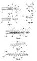
- FIG. 9is a pictorial view of an alternative embodiment of the embolic device of the present invention comprising a chain of linked beads
- FIG. 10is a partial longitudinal cross-sectional view of an alternative embodiment of the embolic device of the present invention comprising a chain of links;
- FIG. 11is a pictorial view of an alternative embodiment of the embolic device of the present invention comprising a sequence of beads having faceted ends and a pair of filaments disposed therein;
- FIG. 12is a partial sectional-pictorial view of a three-lumen catheter incorporating a cutting device for cutting the string of beads according to the present invention.
- FIG. 13is a longitudinal cross-sectional view of the catheter of FIG. 12 showing the cutting device in use.
- FIG. 1shows the embolic device 10 of the present invention partially disposed within a catheter 12 .
- embolic deviceand thrombogenic device are used interchangeably to refer to the invention as a whole.
- the devicemay be used to initiate thrombogenesis (the formation of a blood clot), angiogenesis (development of blood vessels), fibrogenesis (formation of fibrous tissue), or to form an embolism (an obstruction) in a body passageway. Additionally, the device may simply serve as a drug delivery device for delivering medicament to a selected target location within the anatomy.
- the device 10generally comprises a sequence of miniature beads 14 disposed along a flexible linear filament 16 .
- a flexible linear devicesuch as a string of beads
- a linear sequence of solid elements connected by a flexible filamentcan be pushed in a manner similar to a solid rod.
- the solid elementsare forced together in a line as constrained by the catheter lumen, and the flexible filament typically assumes a slack configuration between solid elements.
- the string of beads 10must have adequate compression strength when constrained within the catheter 12 so that it may be pushed through the catheter with a plunger rod or wire 18 , and out the distal end 12 a of the catheter to the target location.
- the string of beadsmay be forced out of the catheter by injection of a liquid.
- a flexible string of beadsis well suited to pushing through a catheter because it handles sharp curves well, and is inherently atraumatic.
- the beads 14may be formed to slide and/or pivot on the filament 16 , or may be fixedly attached thereto, or some combination thereof. For example, some of the beads may be fixed to the filament, with others being slidable on the filament. The fixed beads may even be integrally formed of the material of the filament.
- the beads 14preferably have diameters of from 0.002 inches to 0.0018 inches, and may be made of a variety of biocompatible materials, including polymers, radiopaque polymers, metals, metal alloys, etc.
- a usermay control the density of the string.
- suitable polymer materialssuch as polyethylene or polypropylene will form beads having a density less than blood.
- metalssuch as platinum or platinum alloy
- the resulting devicewould have a density greater than blood.
- individual beadscould also be formed of more than one material, such as a polymer bead with a coating of platinum or other biocompatible metal.
- the string of beadsmay also be comprised of beads of several different materials, placed in such a fashion as to provide the desired density and/or to perform other functions.
- the beadsmay be alternatively formed of magnetized material, and stick together within the body cavity to form the desired thrombogenic mass.
- the catheter or other delivery means, or even the beads themselvescould provide a chemical agent such as a hydrophobic adhesive which causes the beads to adhere to each other in the desired location.
- the surface of the beads 14may be chemically treated or coated to make them very thrombogenic.
- the surfaceis preferably roughened or made porous.
- the beadsmay be irregularly shaped to present a larger exterior surface, and this, along with the porosity, serves to promote thrombogenicity.
- the beads 14are preferably provided with a coating of a blood soluble polymer, such as polyvinyl alcohol. This coating allows the device to be easily manipulated for a period of time without clotting, until the coating dissolves. During delivery of the device, the coating inhibits thrombosis. After a brief time, however, the coating dissolves, allowing thrombosis to begin.
- the beads and filamentsthemselves may also be configured to dissolve, so that when the device has performed its task there are no foreign objects remaining in the body which can be swept away to cause unwanted blockage or clotting.
- the beads 14may be either porous or hollow, and may be impregnated (if porous) or filled (if hollow) with a medicament for controlled release into the interior of the body. With porous beads, the medicament solution would be absorbed into the bead by the capillary effect, and then when the bead is deposited at the target site, the solution will be discharged by diffusion—by blood flowing therepast and thereabout.
- the beads themselvesmay also be soluble, whether hollow or merely porous, allowing the drug contained therein to be slowly released as the bead dissolves.
- medicamentswhich may be delivered by this method include clotting factors (to encourage thrombosis), vascular endothelial growth factors (to promote revascularization), or anti-angiogenesis drugs for control of tumor growth. It will be apparent that other drugs may be delivered in this way.
- the filament 16can be multi or mono filament polymer or single or multistrand metal, and can be malleable or resilient. Accordingly, the mechanical properties of the filament may be carefully controlled to achieve the desired operation.
- resilient filamentsmay be formed to have a preferred memory position, such as straight, or curved, or may have a predetermined shape, such as a ball or helical coil, or tangled “fuzz.” With spring-like properties, as the string of beads is packed into a body cavity, the spring force helps bias the device within the cavity, particularly where the cavity has a small neck.
- the filamentmay be formed of malleable material, such as copper or other metal, so that when the filament is bent, twisted, and packed into place it retains its contorted shape.
- the string of beads as describedis less likely to break or cause tissue damage than other embolic devices because it is flexible and does not have sharp edges.
- implantable rigid devicesincluding drug delivery devices such as Norplant®, tend to be moved by the flexing of muscles, and occasionally cut through body tissues, such as emerging through the skin.
- the flexible string of beadsis also less likely to migrate within the body because when one end becomes dislodged, its movement is less likely to cause the other end to also become dislodged because of the flexibility of the filament.
- FIG. 2there is shown a side, cross-sectional view of a blood vessel 24 in which an aneurysm 26 is shown formed in one side of the vessel.
- a fragmented view of a catheter 12is shown threaded in the vessel 24 , with a distal end 12 a positioned adjacent the neck 28 of the aneurysm 26 .
- the catheter 12is threaded through the vasculature or body passageway 24 to the site at which the embolic device 10 is to be disposed.
- the purpose of such disposalis to provide an occlusion in the passageway to allow for coagulation of blood to prevent further flow, or to cause scarring in the aneurysm 26 to thereby fill the aneurysm with scar tissue to prevent the bursting thereof, etc.
- the string of beads 10is shown as being coiled or tangled within the aneurysm 26 , but when threaded through the catheter 12 it is straightened to allow it to be pushed. Then when the end section is pushed out the terminal end 12 a of the catheter, it resumes a coiled or tangled condition as shown, to substantially fill and pack the aneurysm with a tangled mass of the interconnected miniature beads.
- the filamentis formed of a malleable material
- the string of beadsmay be twisted and packed into the cavity to form a tangled mass which retains the tangled shape. If it is formed of a material having spring properties, it will tend to push against the sides of the aneurism, and thus hold itself within the cavity.
- the string of beadsmay be preconfigured to a desired length before insertion into the delivery catheter. Then the entire string of beads may be delivered to the target location, and the pushing device and delivery catheter may then be removed. Alternatively the string of beads may have a length which is longer than actually needed. In such cases, when a suitable quantity of the string of beads is extended beyond the distal end of the catheter to the target location, the distal end of the string of beads may be severed or cut from the remainder of the string, and the unused string may be withdrawn with the pushing device and the catheter. Severance of the distal end of the string of beads may be accomplished by a number of methods.
- the delivery catheter 12may be configured with a cutting device 30 at its distal end 12 a for cutting the embolic device 10 at the end of a given procedure.
- a suitable cutting device 30is shown in more detail in FIGS. 12 and 13.
- the cutting device 30comprises a high strength flexible cutting filament 220 , such as a Kevlar® fiber, which is threaded through two minor lumens 222 a and 222 b formed generally in one side of a three-lumen catheter 224 .
- the two minor lumensare provided with openings 228 which communicate with the major lumen 230 of the catheter.
- the major lumen 230is the passageway through which the string of beads is extended.
- the cutting filament 220extends from the proximal end of the catheter through the first minor lumen 222 a , through the corresponding opening 228 , into the major lumen 230 of the catheter where it forms a loop 221 around the periphery of the major lumen, and extends into the opening 228 associated with the second minor lumen 222 b and back toward the proximal end of the catheter.
- At least the loop portion 221 of the cutting filament 220preferably has an abrasive surface, so as to allow cutting of the linear filament 16 of the string of beads via a sawing motion if needed.
- the cutting filament 220may also be non-abrasive, and cut the linear filament simply by breaking it.
- the cutting filament 220resides within a recess or niche 232 , shown more clearly in FIG. 13, formed in the side wall of the catheter in the region of the openings 228 .
- This nicheallows the loop 221 of the cutting filament 220 to be out of the way and not obstruct the major lumen of the catheter during extension and placement of the string of beads.
- the userpulls on the proximal end of the cutting filament, which extends out the proximal end of the triple lumen catheter, drawing the filament loop 221 out of the recess 232 , toward the openings 228 , and transversely onto the linear filament 16 .
- the usermay cut the string of beads simply by breaking the linear filament 16 by pulling on one end of the cutting filament 220 .
- the usermay cut the string of beads by performing a sawing motion—alternately pulling on first one end, then the other end, of the cutting filament 220 .
- the linear filament 16is formed of a relatively weak polymer material, it may be cut or broken simply by pulling on the proximal end of the cutting filament. However, if the linear filament 16 is formed of a stronger material, such as metal, it may require a sawing action to sever.
- the linear filament 16may be severed by means of mechanical vibration.
- the linear filamentmay be connected to a pusher rod 18 , which is provided with a discontinuity 32 toward its distal end (see FIG. 1 ), which allows it to be detached by means of mechanical energy transmitted down the guidewire.
- an ultrasound generator(not shown) would be connected to the proximal end of wire 18 and an ultrasound signal applied thereto.
- the frequency and amplitude of the signal(observed on a spectrum analyzer) would be selected to produce high stress in the discontinuity 32 , depending on the natural frequency of the pusher rod 18 and attached string of beads 10 , fatiguing the wire 18 so that it breaks, ruptures, or otherwise separates at the discontinuity, leaving the string of beads at the target location. Because the system uses vibrations in the ultrasonic range, the separation is accomplished rapidly, reliably and without pain to the subject.
- discontinuitiesmay be provided at selected locations on the linear filament itself, such as between fixedly attached beads, to allow severance of the string of beads at a desired location through mechanical vibration as described above.
- a more detailed description of an endovascular wire device with a distal end detachable by means of mechanical vibrationsis outlined in U.S. Pat. No. 6,022,369, the disclosure thereof being incorporated herein by reference.
- the string of beads 10may be comprised of beads of several different materials, placed in such a fashion as to provide the desired density and/or to perform other functions.
- the stringmay be made with a repeating pattern of one heavy metal bead 34 , followed by several lighter polymer beads 36 .
- the number of polymer beadsmay be selected to precisely control the average density of the resulting string.
- the metal beadmay be formed of platinum, for example, to serve as a radiopaque marker to assist in insertion and precise placement of the device.
- the body's own clottingis generally sufficient to anchor the device in place.
- an end of the string of beadscould be fixed at a suture point, or within cauterized adjacent tissue.
- the linear sequence of beadscould be provided with an anchor element on one end for anchoring the string of beads in body tissues, and thereby prevent migration of the string of beads.
- One application of the present inventionis in treatment of cardiac damage.
- a recently developed method of restoring blood flow to damaged regions of the cardiac muscleinvolves puncturing the heart muscle (usually only partway through) using a laser, typically from within a chamber of the heart, so as to form one or more small holes in the wall of the heart. These holes create a wound which triggers angiogenesis, spurring the formation of collateral blood vessels and capillaries which restore blood flow around damaged or blocked arteries to regions of the heart muscle suffering from inadequate blood flow.
- FIG. 3Ais a side view of one embodiment of an embolic device according to the present invention having a hook-type anchor element 42 disposed at one end.
- the hook-type anchor element 42comprises one or more protruding elements 44 , which are tapered in a direction opposite the direction in which the device is to be pushed into the hole.
- the anchor 42 and the protruding elements 44may be formed to be relatively rigid like the barbs on a fish hook, or may be relatively flexible like the bristles of a brush. Accordingly, the anchor 42 may be formed of relatively flexible material, such as biocompatible polymers, or more rigid material such as metal. Because the protruding elements are tapered opposite to the direction in which the anchor is inserted into the hole, when the anchor is forced into the hole, the protruding elements may deflect toward the center shaft of the hook, in the case of flexible protruding elements, or deflect the surrounding tissue, in the case of more rigid protruding elements, allowing the anchor to slide into the hole relatively easily. Once in place, however, the protruding elements hook into the surrounding tissue to resist any force which tends to pull the string out of the hole.
- the anchor elementmay comprise ingrowth material, which allows body tissue to grow around it, and thus becomes intertwined with the patient's natural tissue.
- FIG. 3Bis a side view of the embolic device of FIG. 3A having an anchor element 50 comprised of a ball of thrombogenic fuzz.
- the fuzzis formed of a biocompatible material which allows body tissues to grow within the ball of fuzz, thus firmly anchoring the string of beads over a period of time.
- the ball of fuzz and the attached string of beadsmay be formed of a material which gradually dissolves in body fluids, thus allowing the device to serve its purpose of spurring new blood vessel growth, without creating a permanent foreign structure within the patient.
- FIG. 3 A and FIG. 3Bmay be combined, such that the anchor comprises a hooked or barbed element with a ball of fuzz attached.
- This embodimentwould provide the advantages of immediate mechanical anchorage provided by the hooks or barbs, with the gradually increasing anchor strength provided as the body tissues grow around the fuzz material.
- FIG. 3Cis a side view of an embodiment of the embolic device of FIG. 3A having a perforated plate anchor element 52 , which is configured to be attached at a suture point or within cauterized tissue.
- the openings 54 in the perforated plate 52allow suture filaments to pass through the plate to hold it firmly in place.
- the openings 54may help to hold the device in cauterized tissue, or mays assist in anchorage of the device of this and other embodiments described herein via biocompatible adhesives which are well known in the art.
- the adhesivesmay be activated by body heat or by contact with blood, and may also be configured to gradually dissolve in body fluids after the string of beads is anchored by surrounding tissue growth.
- FIG. 3Dis a side view of yet another alternative embodiment of the embolic device of FIG. 3A having a clip type anchor element 56 .
- the clip 56may be formed of metals or polymers, and may take a variety of forms and operate on several different principles. As shown in FIG. 3D, the clip 56 comprises a loop of malleable metal, which is open at its distal end 58 . When the string of beads is put in place, the distal end is positioned such that a quantity of body tissue is disposed within the opening, and the clip is then crushed or mashed so as to tightly grip the tissue. The malleable metal material deforms to the crushed configuration, causing the clip to retain its new compacted shape and hold the string of beads in place.
- the clipmay be formed of resilient material, whether metal or polymer, which is formed in a naturally closed position.
- the clipWhen the string of beads is positioned at the target location, the clip may be forced open and attached to adjacent tissue. Because the resilient material of the clip tends to hold itself closed, the clip will firmly grip the tissue to anchor the string of beads in place.
- the string of beads devicespeeds the healing of the hole, and may also provide a means for the introduction of various drugs to speed the healing and angiogenesis process as described above.
- the beads 14may be formed in various shapes, other than spherical, to improve the pushability of the device in the catheter 12 , and for other purposes.
- Various alternative shapesare shown in FIGS. 4-8.
- adjacent beads 64 of a string of beads 60may be provided with flattened surfaces 68 on facing sides to allow them to “stack” against each other when pushed within the catheter 62 .
- the flattened sides 68may also be provided with a hollow or indentation 70 for receiving the slack filament 66 when the beads are pushed together.
- FIG. 5depicts an alternative embodiment of a string of beads 80 wherein the beads 82 are generally round, and have indentations or hollows 84 formed on each side, such that the slack filament 86 may occupy the space of adjacent indentations 84 when the string of beads is pushed together.
- the string of beads 90may be comprised of a sequence of nesting beads 92 .
- Each generally rounded bead 92has an indentation 94 on a distal end, which is configured to conform to the shape of the proximal end 96 of the adjacent bead 92 .
- the indentation 94 of each beadis also configured to accommodate the slack filament 98 when beads are pushed together.
- FIG. 7provides a pictorial view of the embodiment of FIG. 6 . From this view it is more apparent how the indentation 94 on the distal end of each bead 92 is configured to receive and partially surround the proximal end 96 of an adjacent bead when the beads are pushed together.
- FIG. 8shows an alternative embodiment of an embolic device 120 comprising a linear sequence of interlocking beads 122 .
- Each bead 122is comprised of a generally spherical main body portion 124 , and a projecting lobe or ball 126 .
- the main body portioncomprises a socket 128 at its distal end, which is configured to receive the ball 126 of the preceding bead 122 .
- adjacent beadsare free to pivot and/or rotate relative to each other, forming an elongate, flexible string of interconnected beads.
- the beads 122preferably have main body diameters of from 0.004 to 0.018 inches.
- the beads 122also preferably have central bores 130 through which filament 132 is threaded to maintain the beads connected together in a chain.
- the beadsare slidably disposed on the filament, and the string is allowed to tangle upon deployment from the catheter.
- deployment of the interlocking beads 122may be carried out by inserting the string of beads, threaded on the filament 132 , into a catheter.
- the beads 122may be deposited out the distal end of the catheter by retracting the filament 132 so that the particles fall off the end of the filament.
- each beadbecomes disconnected from the adjacent rear particle when the ball 126 slides out of the socket 128 .
- the ball and socket structuremay be constructed to entirely hold adjacent beads together, so that an internal filament is not required to maintain the beads in the form of a flexible string.
- the beadsmight illustratively be made of platinum alloy or radiopaque polymer. Additionally, the central filament 130 could be preformed to assume a “fuzzball” or other desired shape when released from the distal end of the catheter. The beads would serve to reduce the chance of the fine central filament causing trauma to the vessel wall by increasing its effective diameter while not increasing its bending stiffness substantially.
- FIG. 9shows an alternative embodiment of an embolic device 140 comprising a chain of linked beads 142 .
- each bead 142comprises a pair of oppositely directed links 144 a and b , which are interconnected with similar links of adjacent beads to form a chain, rather than being disposed upon a filament.
- the beads and linksmay be formed of polymers, metals, or any other suitable biocompatible material.
- the chain of linked beads 140may be pushed through a catheter for disposition at a target location, where it may fold back upon itself in a tangled mass to promote thrombosis.
- the devicemay simply comprise a chain 160 as shown in FIG. 10 .
- This embolic device 160comprises a plurality of links 162 which are formed in the manner of ordinary chains.
- the embolic chainmay also be formed of polymers, metals, or any other suitable biocompatible material. The flexible nature of the chain allows it to tangle or curl up when released to occupy the desired volume, and the plurality of hollow spaces within the chain links helps encourage clotting by providing many small spaces for trapping blood and fluid.
- FIG. 11shows an alternative embodiment of an embolic device 200 comprising a sequence of beads 202 having faceted ends 204 and a pair of filaments 206 and 208 disposed therethrough.
- the beads 202have two parallel lumens 210 and 212 through which filaments 206 and 208 slidably pass, and are fixedly anchored in an end bead 214 .
- the facets 204 of opposing beadsare pulled together, causing the sequence of beads 202 to contract into a curved shape.
- the curved shapemay take many forms, depending on the geometry of the beads.
- the facetsmay be configured so that when contracted the string of beads forms a circular shape, a helical shape, or some other desired shape.
- the facetsmay be randomly configured, causing the string of beads to form a randomly curved and twisted shape when the filaments are pulled. Forming the string of beads into a curved or twisted shape advantageously reduces the chance that the device will escape from the target location.
Landscapes
- Health & Medical Sciences (AREA)
- Surgery (AREA)
- Life Sciences & Earth Sciences (AREA)
- Biomedical Technology (AREA)
- Medical Informatics (AREA)
- Vascular Medicine (AREA)
- Reproductive Health (AREA)
- Engineering & Computer Science (AREA)
- Veterinary Medicine (AREA)
- Heart & Thoracic Surgery (AREA)
- Nuclear Medicine, Radiotherapy & Molecular Imaging (AREA)
- Molecular Biology (AREA)
- Animal Behavior & Ethology (AREA)
- General Health & Medical Sciences (AREA)
- Public Health (AREA)
- Neurosurgery (AREA)
- Surgical Instruments (AREA)
- Control Of Vending Devices And Auxiliary Devices For Vending Devices (AREA)
- Adornments (AREA)
Abstract
Description
Claims (39)
Priority Applications (7)
| Application Number | Priority Date | Filing Date | Title |
|---|---|---|---|
| US09/588,251US6530934B1 (en) | 2000-06-06 | 2000-06-06 | Embolic device composed of a linear sequence of miniature beads |
| PCT/US2001/018414WO2001093920A2 (en) | 2000-06-06 | 2001-06-06 | Embolic device composed of a linear sequence of miniature beads |
| CA002412404ACA2412404C (en) | 2000-06-06 | 2001-06-06 | Embolic device composed of a linear sequence of miniature beads |
| DE60142563TDE60142563D1 (en) | 2000-06-06 | 2001-06-06 | EMBOLIZING DEVICE ASSEMBLED FROM A LINEAR SEQUENCE OF MINIATURE PEARLS |
| AU2001266754AAU2001266754A1 (en) | 2000-06-06 | 2001-06-06 | Embolic device composed of a linear sequence of miniature beads |
| EP01944331AEP1286622B1 (en) | 2000-06-06 | 2001-06-06 | Embolic device composed of a linear sequence of miniature beads |
| AT01944331TATE473697T1 (en) | 2000-06-06 | 2001-06-06 | EMBOLIZATION DEVICE COMPOSED OF A LINEAR SEQUENCE OF MINIATURE BEADS |
Applications Claiming Priority (1)
| Application Number | Priority Date | Filing Date | Title |
|---|---|---|---|
| US09/588,251US6530934B1 (en) | 2000-06-06 | 2000-06-06 | Embolic device composed of a linear sequence of miniature beads |
Publications (1)
| Publication Number | Publication Date |
|---|---|
| US6530934B1true US6530934B1 (en) | 2003-03-11 |
Family
ID=24353093
Family Applications (1)
| Application Number | Title | Priority Date | Filing Date |
|---|---|---|---|
| US09/588,251Expired - Fee RelatedUS6530934B1 (en) | 2000-06-06 | 2000-06-06 | Embolic device composed of a linear sequence of miniature beads |
Country Status (7)
| Country | Link |
|---|---|
| US (1) | US6530934B1 (en) |
| EP (1) | EP1286622B1 (en) |
| AT (1) | ATE473697T1 (en) |
| AU (1) | AU2001266754A1 (en) |
| CA (1) | CA2412404C (en) |
| DE (1) | DE60142563D1 (en) |
| WO (1) | WO2001093920A2 (en) |
Cited By (145)
| Publication number | Priority date | Publication date | Assignee | Title |
|---|---|---|---|---|
| US20020177855A1 (en)* | 1999-10-04 | 2002-11-28 | Greene George R. | Method of manufacturing expansile filamentous embolization devices |
| US20030004568A1 (en)* | 2001-05-04 | 2003-01-02 | Concentric Medical | Coated combination vaso-occlusive device |
| US20030004531A1 (en)* | 2001-06-13 | 2003-01-02 | Jones Donald K. | Occluding vasculature of a patient using embolic coil with improved platelet adhesion |
| US20040167437A1 (en)* | 2003-02-26 | 2004-08-26 | Sharrow James S. | Articulating intracorporal medical device |
| US20050060017A1 (en)* | 2003-09-15 | 2005-03-17 | Fischell Robert E. | Means and method for the treatment of cerebral aneurysms |
| US20050065516A1 (en)* | 2003-09-24 | 2005-03-24 | Tae-Ahn Jahng | Method and apparatus for flexible fixation of a spine |
| US20050085836A1 (en)* | 2003-09-12 | 2005-04-21 | Jean Raymond | Methods and devices for endothelial denudation to prevent recanalization after embolization |
| US20050124991A1 (en)* | 2003-12-05 | 2005-06-09 | Tae-Ahn Jahng | Method and apparatus for flexible fixation of a spine |
| US20050203513A1 (en)* | 2003-09-24 | 2005-09-15 | Tae-Ahn Jahng | Spinal stabilization device |
| US20050203514A1 (en)* | 2003-09-24 | 2005-09-15 | Tae-Ahn Jahng | Adjustable spinal stabilization system |
| US20050238870A1 (en)* | 2004-04-22 | 2005-10-27 | Marcia Buiser | Embolization |
| US20050267444A1 (en)* | 2003-03-27 | 2005-12-01 | Stephen Griffin | Medical device |
| EP1621148A1 (en)* | 2004-07-30 | 2006-02-01 | Cordis Neurovascular, Inc. | Embolic device deployment system with filament release |
| US20060025802A1 (en)* | 2004-07-30 | 2006-02-02 | Sowers William W | Embolic coil delivery system with U-shaped fiber release mechanism |
| US20060025803A1 (en)* | 2004-07-30 | 2006-02-02 | Vladimir Mitelberg | Embolic device delivery system with retractable partially coiled-fiber release |
| US20060122691A1 (en)* | 1998-12-03 | 2006-06-08 | Jacob Richter | Hybrid stent |
| US20060129175A1 (en)* | 2004-12-09 | 2006-06-15 | Scimed Life Systems, Inc. | Catheter including a compliant balloon |
| US20060133763A1 (en)* | 2004-09-11 | 2006-06-22 | Vinayak Dangui | Method and apparatus for modeling the modal properties of optical waveguides |
| US20060178727A1 (en)* | 1998-12-03 | 2006-08-10 | Jacob Richter | Hybrid amorphous metal alloy stent |
| US20060184196A1 (en)* | 2000-09-26 | 2006-08-17 | Microvention, Inc. | Microcoil vaso-occlusive device with multi-axis secondary configuration |
| US20060189896A1 (en)* | 1995-12-07 | 2006-08-24 | Davis Clark C | Medical device with collapse-resistant liner and mehtod of making same |
| US20060206143A1 (en)* | 2001-06-14 | 2006-09-14 | Stephen West | Aneurysm embolization device and development system |
| US20060206139A1 (en)* | 2005-01-19 | 2006-09-14 | Tekulve Kurt J | Vascular occlusion device |
| US7169118B2 (en) | 2003-02-26 | 2007-01-30 | Scimed Life Systems, Inc. | Elongate medical device with distal cap |
| US20070066900A1 (en)* | 2005-09-22 | 2007-03-22 | Boston Scientific Scimed, Inc. | Intravascular ultrasound catheter |
| US20070100285A1 (en)* | 2005-10-27 | 2007-05-03 | Boston Scientific Scimed, Inc. | Elongate medical device with continuous reinforcement member |
| US20070219642A1 (en)* | 1998-12-03 | 2007-09-20 | Jacob Richter | Hybrid stent having a fiber or wire backbone |
| US20070243228A1 (en)* | 2006-04-13 | 2007-10-18 | Mckay William F | Drug depot implant designs and methods of implantation |
| US20070276380A1 (en)* | 2003-09-24 | 2007-11-29 | Tae-Ahn Jahng | Spinal stabilization device |
| US20080021313A1 (en)* | 2006-07-06 | 2008-01-24 | Boston Scientific Scimed, Inc. | Electroactive polymer radiopaque marker |
| US20080021407A1 (en)* | 2002-07-25 | 2008-01-24 | Precision Vascular Systems, Inc. | Medical device for navigation through anatomy and method of making same |
| US20080064989A1 (en)* | 2006-09-13 | 2008-03-13 | Boston Scientific Scimed, Inc. | Crossing guidewire |
| US20080077119A1 (en)* | 2001-07-05 | 2008-03-27 | Precision Vascular Systems, Inc. | Torqueable soft tip medical device and method of usage |
| US20080086854A1 (en)* | 2002-12-10 | 2008-04-17 | Boyd Robert R | Articulated Elements And Methods For Use |
| US20080103477A1 (en)* | 2004-10-26 | 2008-05-01 | Jones Donald K | Method Of Delivering Embolic Particles To An Aneurysm |
| US20080147170A1 (en)* | 2006-12-15 | 2008-06-19 | Boston Scientific Scimed, Inc. | Medical device including structure for crossing an occlusion in a vessel |
| US20080188819A1 (en)* | 2006-07-07 | 2008-08-07 | Kloke Tim M | Beaded Wound Spacer Device |
| US20080228215A1 (en)* | 2007-03-13 | 2008-09-18 | Micro Therapeutics, Inc. | Implant including a coil and a stretch-resistant member |
| US20080262474A1 (en)* | 2007-04-20 | 2008-10-23 | Boston Scientific Scimed, Inc. | Medical device |
| US20090036834A1 (en)* | 2007-08-03 | 2009-02-05 | Boston Scientific Scimed, Inc. | Elongate medical device having enhanced torque and methods thereof |
| US20090036832A1 (en)* | 2007-08-03 | 2009-02-05 | Boston Scientific Scimed, Inc. | Guidewires and methods for manufacturing guidewires |
| US20090036833A1 (en)* | 2007-08-02 | 2009-02-05 | Boston Scientific Scimed, Inc. | Composite elongate medical device including distal tubular member |
| US20090043228A1 (en)* | 2007-08-06 | 2009-02-12 | Boston Scientific Scimed, Inc. | Laser shock peening of medical devices |
| US20090043283A1 (en)* | 2007-08-07 | 2009-02-12 | Boston Scientific Scimed, Inc. | Microfabricated catheter with improved bonding structure |
| US20090043276A1 (en)* | 2007-08-09 | 2009-02-12 | Boston Scientific Scimed, Inc. | Drug delivery device, compositions and methods relating thereto |
| WO2008135551A3 (en)* | 2007-05-03 | 2009-04-09 | Coloplast As | A filler with controlled absorption swell for wound bed cavity |
| US20090112249A1 (en)* | 2007-10-19 | 2009-04-30 | Coherex Medical, Inc. | Medical device for modification of left atrial appendage and related systems and methods |
| US20090202609A1 (en)* | 2008-01-06 | 2009-08-13 | Keough Steven J | Medical device with coating composition |
| US20100004665A1 (en)* | 2007-02-23 | 2010-01-07 | Korea University Industrial & Academic Collaboration Foundation | Bead for stitching, vacuum cap for suction internal organ and apparatus for stitching internal organ using the same |
| US20100004726A1 (en)* | 2000-03-22 | 2010-01-07 | Endovascular Technologies, Inc. | Self-expanding pseudo-braided intravascular device |
| US20100021516A1 (en)* | 2008-07-23 | 2010-01-28 | Warsaw Orthopedic, Inc. | Drug depots having one or more anchoring members |
| US20100063480A1 (en)* | 2008-09-10 | 2010-03-11 | Boston Scientific Scimed, Inc. | Medical devices and tapered tubular members for use in medical devices |
| US20100063479A1 (en)* | 2008-09-10 | 2010-03-11 | Boston Scientific Scimed, Inc. | Small profile, tubular component design and method of manufacture |
| US20100076573A1 (en)* | 2002-04-26 | 2010-03-25 | Kugler Chad J | Methods and apparatus for treating body tissue sphincters and the like |
| US20100106136A1 (en)* | 2008-10-29 | 2010-04-29 | Warsaw Orthopedic, Inc. | Drug delivery device with sliding cartridge |
| US20100106132A1 (en)* | 2008-10-29 | 2010-04-29 | Warsaw Orthopedic, Inc. | Drug cartridge for delivering a drug depot comprising superior and inferior covers |
| US20100106133A1 (en)* | 2008-10-29 | 2010-04-29 | Warsaw Orthopedic, Inc. | Drug cartridge for delivering a drug depot comprising a bulking agent and/or cover |
| US20100106137A1 (en)* | 2008-10-29 | 2010-04-29 | Warsaw Orthopedic, Inc. | Drug Delivery System |
| US20100145308A1 (en)* | 2008-12-10 | 2010-06-10 | Boston Scientific Scimed, Inc. | Medical devices with a slotted tubular member having improved stress distribution |
| US20100152776A1 (en)* | 2008-12-17 | 2010-06-17 | Synthes Usa, Llc | Posterior spine dynamic stabilizer |
| US7763077B2 (en) | 2003-12-24 | 2010-07-27 | Biomerix Corporation | Repair of spinal annular defects and annulo-nucleoplasty regeneration |
| US20100228285A1 (en)* | 2009-01-08 | 2010-09-09 | Coherex Medical, Inc. | Medical device for modification of left atrial appendage and related systems and methods |
| US7803395B2 (en) | 2003-05-15 | 2010-09-28 | Biomerix Corporation | Reticulated elastomeric matrices, their manufacture and use in implantable devices |
| US20100274350A1 (en)* | 2009-04-22 | 2010-10-28 | Medinol Ltd. | Helical hybrid stent |
| US7824345B2 (en) | 2003-12-22 | 2010-11-02 | Boston Scientific Scimed, Inc. | Medical device with push force limiter |
| US7841994B2 (en) | 2007-11-02 | 2010-11-30 | Boston Scientific Scimed, Inc. | Medical device for crossing an occlusion in a vessel |
| US20100324587A1 (en)* | 2009-06-17 | 2010-12-23 | Coherex Medical, Inc. | Medical device for modification of left atrial appendage and related systems and methods |
| US20110034906A1 (en)* | 2009-08-05 | 2011-02-10 | Tyco Healthcare Group Lp | Surgical Wound Dressing Incorporating Connected Hydrogel Beads Having an Embedded Electrode Therein |
| US7914467B2 (en) | 2002-07-25 | 2011-03-29 | Boston Scientific Scimed, Inc. | Tubular member having tapered transition for use in a medical device |
| US20110106110A1 (en)* | 2009-10-30 | 2011-05-05 | Warsaw Orthopedic, Inc. | Devices and methods for implanting a plurality of drug depots having one or more anchoring members |
| US20110184452A1 (en)* | 2010-01-28 | 2011-07-28 | Micro Therapeutics, Inc. | Vascular remodeling device |
| US20110184453A1 (en)* | 2010-01-28 | 2011-07-28 | Micro Therapeutics, Inc. | Vascular remodeling device |
| US20110208227A1 (en)* | 2008-04-21 | 2011-08-25 | Becking Frank P | Filamentary Devices For Treatment Of Vascular Defects |
| US20120029551A1 (en)* | 2008-10-10 | 2012-02-02 | Milux Holding S.A. | Apparatus for treating gerd |
| US8137293B2 (en) | 2009-11-17 | 2012-03-20 | Boston Scientific Scimed, Inc. | Guidewires including a porous nickel-titanium alloy |
| JP2012507366A (en)* | 2008-10-30 | 2012-03-29 | ウォーソー・オーソペディック・インコーポレーテッド | Drug depot with anchor |
| US20120203345A1 (en)* | 2007-04-26 | 2012-08-09 | Voorhies Rand M | Lumbar Disc Replacement Implant for Posterior Implantation with Dynamic Spinal Stabilization Device and Method |
| US20120303052A1 (en)* | 2011-05-24 | 2012-11-29 | Connor Robert A | Aneurysm occlusion by rotational dispensation of mass |
| US8376961B2 (en) | 2008-04-07 | 2013-02-19 | Boston Scientific Scimed, Inc. | Micromachined composite guidewire structure with anisotropic bending properties |
| US8377035B2 (en) | 2003-01-17 | 2013-02-19 | Boston Scientific Scimed, Inc. | Unbalanced reinforcement members for medical device |
| US8382821B2 (en) | 1998-12-03 | 2013-02-26 | Medinol Ltd. | Helical hybrid stent |
| US20130066359A1 (en)* | 2011-09-13 | 2013-03-14 | Stryker Nv Operations Limited | Vaso-occlusive device |
| US8551021B2 (en) | 2010-03-31 | 2013-10-08 | Boston Scientific Scimed, Inc. | Guidewire with an improved flexural rigidity profile |
| US20140172001A1 (en)* | 2011-02-11 | 2014-06-19 | Covidien Lp | Two-stage deployment aneurysm embolization devices |
| US8777978B2 (en) | 2006-04-17 | 2014-07-15 | Covidien Lp | System and method for mechanically positioning intravascular implants |
| US8777979B2 (en) | 2006-04-17 | 2014-07-15 | Covidien Lp | System and method for mechanically positioning intravascular implants |
| US8795202B2 (en) | 2011-02-04 | 2014-08-05 | Boston Scientific Scimed, Inc. | Guidewires and methods for making and using the same |
| US8801747B2 (en) | 2007-03-13 | 2014-08-12 | Covidien Lp | Implant, a mandrel, and a method of forming an implant |
| US8821477B2 (en) | 2007-08-06 | 2014-09-02 | Boston Scientific Scimed, Inc. | Alternative micromachined structures |
| US20140257320A1 (en)* | 2013-03-11 | 2014-09-11 | Microvention, Inc. | Implantable Device With Adhesive Properties |
| US20140277097A1 (en)* | 2013-03-13 | 2014-09-18 | Endoshape Inc. | Continuous embolic coil and methods and devices for delivery of the same |
| US9011480B2 (en) | 2012-01-20 | 2015-04-21 | Covidien Lp | Aneurysm treatment coils |
| US9033912B2 (en) | 2012-03-28 | 2015-05-19 | Warsaw Orthopedic, Inc. | Drug delivery system |
| US9039755B2 (en) | 2003-06-27 | 2015-05-26 | Medinol Ltd. | Helical hybrid stent |
| US9050095B2 (en) | 2004-09-22 | 2015-06-09 | Covidien Lp | Medical implant |
| US9060886B2 (en) | 2011-09-29 | 2015-06-23 | Covidien Lp | Vascular remodeling device |
| US9072874B2 (en) | 2011-05-13 | 2015-07-07 | Boston Scientific Scimed, Inc. | Medical devices with a heat transfer region and a heat sink region and methods for manufacturing medical devices |
| US9089332B2 (en) | 2011-03-25 | 2015-07-28 | Covidien Lp | Vascular remodeling device |
| US9095342B2 (en) | 2009-11-09 | 2015-08-04 | Covidien Lp | Braid ball embolic device features |
| US9155671B2 (en) | 2012-10-16 | 2015-10-13 | Surmodics, Inc. | Wound packing device and methods |
| US9179918B2 (en) | 2008-07-22 | 2015-11-10 | Covidien Lp | Vascular remodeling device |
| US9198665B2 (en) | 2004-09-22 | 2015-12-01 | Covidien Lp | Micro-spiral implantation device |
| US9295571B2 (en) | 2013-01-17 | 2016-03-29 | Covidien Lp | Methods and apparatus for luminal stenting |
| US9314248B2 (en) | 2012-11-06 | 2016-04-19 | Covidien Lp | Multi-pivot thrombectomy device |
| US20160120551A1 (en)* | 2010-10-21 | 2016-05-05 | Robert A. Connor | Devices and Methods for Occluding a Cerebral Aneurysm |
| US9351716B2 (en) | 2009-06-17 | 2016-05-31 | Coherex Medical, Inc. | Medical device and delivery system for modification of left atrial appendage and methods thereof |
| US20160278785A1 (en)* | 2015-03-26 | 2016-09-29 | Boston Scientific Scimed, Inc. | Biologic-based expandable occlusion devices |
| US9463105B2 (en) | 2013-03-14 | 2016-10-11 | Covidien Lp | Methods and apparatus for luminal stenting |
| US9579104B2 (en) | 2011-11-30 | 2017-02-28 | Covidien Lp | Positioning and detaching implants |
| US9586024B2 (en) | 2011-04-18 | 2017-03-07 | Medtronic Vascular, Inc. | Guide catheter with radiopaque filaments for locating an ostium |
| US9649115B2 (en) | 2009-06-17 | 2017-05-16 | Coherex Medical, Inc. | Medical device for modification of left atrial appendage and related systems and methods |
| US9687245B2 (en) | 2012-03-23 | 2017-06-27 | Covidien Lp | Occlusive devices and methods of use |
| US9693781B2 (en) | 2009-06-17 | 2017-07-04 | Coherex Medical, Inc. | Medical device for modification of left atrial appendage and related systems and methods |
| US9713475B2 (en) | 2014-04-18 | 2017-07-25 | Covidien Lp | Embolic medical devices |
| US20170258617A1 (en)* | 2010-10-19 | 2017-09-14 | Apollo Endosurgery Us, Inc. | Non-Inflatable Gastric Implants and Systems |
| US9764122B2 (en) | 2014-07-25 | 2017-09-19 | Warsaw Orthopedic, Inc. | Drug delivery device and methods having an occluding member |
| US9775978B2 (en) | 2014-07-25 | 2017-10-03 | Warsaw Orthopedic, Inc. | Drug delivery device and methods having a retaining member |
| USD802755S1 (en) | 2016-06-23 | 2017-11-14 | Warsaw Orthopedic, Inc. | Drug pellet cartridge |
| US20170333678A1 (en)* | 2013-12-20 | 2017-11-23 | Microvention, Inc. | Segmented embolic system |
| USD809652S1 (en) | 2014-07-25 | 2018-02-06 | Warsaw Orthopedic, Inc. | Drug delivery device |
| US9901706B2 (en) | 2014-04-11 | 2018-02-27 | Boston Scientific Scimed, Inc. | Catheters and catheter shafts |
| US9901684B2 (en) | 2013-10-17 | 2018-02-27 | Warsaw Orthopedic, Inc. | Drug delivery device with retaining member |
| US9987015B2 (en) | 2014-07-25 | 2018-06-05 | Incumedx, Inc. | Covered embolic coils |
| US10064628B2 (en) | 2009-06-17 | 2018-09-04 | Coherex Medical, Inc. | Medical device for modification of left atrial appendage and related systems and methods |
| US10172634B1 (en) | 2017-10-16 | 2019-01-08 | Michael Bruce Horowitz | Catheter based retrieval device with proximal body having axial freedom of movement |
| US10201457B2 (en) | 2014-08-01 | 2019-02-12 | Surmodics, Inc. | Wound packing device with nanotextured surface |
| US10434261B2 (en) | 2016-11-08 | 2019-10-08 | Warsaw Orthopedic, Inc. | Drug pellet delivery system and method |
| US10478194B2 (en) | 2015-09-23 | 2019-11-19 | Covidien Lp | Occlusive devices |
| US10631969B2 (en) | 2009-06-17 | 2020-04-28 | Coherex Medical, Inc. | Medical device for modification of left atrial appendage and related systems and methods |
| US10736758B2 (en) | 2013-03-15 | 2020-08-11 | Covidien | Occlusive device |
| CN113825455A (en)* | 2019-04-30 | 2021-12-21 | 波士顿科学国际有限公司 | Endoscopic patch applicator |
| US11351048B2 (en) | 2015-11-16 | 2022-06-07 | Boston Scientific Scimed, Inc. | Stent delivery systems with a reinforced deployment sheath |
| US11369355B2 (en) | 2019-06-17 | 2022-06-28 | Coherex Medical, Inc. | Medical device and system for occluding a tissue opening and method thereof |
| US11382643B2 (en) | 2017-10-16 | 2022-07-12 | Retriever Medical, Inc. | Clot removal methods and devices with multiple independently controllable elements |
| US20220218368A1 (en)* | 2019-08-07 | 2022-07-14 | Taiwan Biomaterial Co., Ltd. | Thrombus removal device |
| US11464518B2 (en) | 2008-05-01 | 2022-10-11 | Aneuclose Llc | Proximal concave neck bridge with central lumen and distal net for occluding cerebral aneurysms |
| US11471163B2 (en) | 2008-05-01 | 2022-10-18 | Aneuclose Llc | Intrasaccular aneurysm occlusion device with net or mesh expanded by string-of-pearls embolies |
| US11484322B2 (en) | 2018-01-03 | 2022-11-01 | Aneuclose Llc | Aneurysm neck bridge with a closeable opening or lumen through which embolic material is inserted into the aneurysm sac |
| WO2023014782A1 (en)* | 2021-08-03 | 2023-02-09 | Boston Scientific Scimed, Inc. | Expandable devices and systems |
| US11589881B2 (en) | 2017-10-16 | 2023-02-28 | Retriever Medical, Inc. | Clot removal methods and devices with multiple independently controllable elements |
| EP4201344A1 (en) | 2021-12-24 | 2023-06-28 | Artedrone | Device and system for treatment of a vessel |
| US11707371B2 (en) | 2008-05-13 | 2023-07-25 | Covidien Lp | Braid implant delivery systems |
| US11759614B2 (en) | 2015-11-23 | 2023-09-19 | Warsaw Orthopedic, Inc. | Enhanced stylet for drug depot injector |
| US11812969B2 (en) | 2020-12-03 | 2023-11-14 | Coherex Medical, Inc. | Medical device and system for occluding a tissue opening and method thereof |
| WO2025144858A1 (en)* | 2023-12-27 | 2025-07-03 | Cedars-Sinai Medical Center | Intravesical delivery system |
Families Citing this family (32)
| Publication number | Priority date | Publication date | Assignee | Title |
|---|---|---|---|---|
| US20060292206A1 (en) | 2001-11-26 | 2006-12-28 | Kim Steven W | Devices and methods for treatment of vascular aneurysms |
| US7131997B2 (en) | 2002-03-29 | 2006-11-07 | Scimed Life Systems, Inc. | Tissue treatment |
| US7462366B2 (en) | 2002-03-29 | 2008-12-09 | Boston Scientific Scimed, Inc. | Drug delivery particle |
| US7094369B2 (en) | 2002-03-29 | 2006-08-22 | Scimed Life Systems, Inc. | Processes for manufacturing polymeric microspheres |
| US7053134B2 (en) | 2002-04-04 | 2006-05-30 | Scimed Life Systems, Inc. | Forming a chemically cross-linked particle of a desired shape and diameter |
| US20030204246A1 (en)* | 2002-04-25 | 2003-10-30 | Jack Chu | Aneurysm treatment system and method |
| US7449236B2 (en) | 2002-08-09 | 2008-11-11 | Boston Scientific Scimed, Inc. | Porous polymeric particle comprising polyvinyl alcohol and having interior to surface porosity-gradient |
| US7588825B2 (en) | 2002-10-23 | 2009-09-15 | Boston Scientific Scimed, Inc. | Embolic compositions |
| US7481821B2 (en) | 2002-11-12 | 2009-01-27 | Thomas J. Fogarty | Embolization device and a method of using the same |
| US20040260382A1 (en) | 2003-02-12 | 2004-12-23 | Fogarty Thomas J. | Intravascular implants and methods of using the same |
| US20050015110A1 (en)* | 2003-07-18 | 2005-01-20 | Fogarty Thomas J. | Embolization device and a method of using the same |
| US7371228B2 (en)* | 2003-09-19 | 2008-05-13 | Medtronic Vascular, Inc. | Delivery of therapeutics to treat aneurysms |
| US7901770B2 (en)* | 2003-11-04 | 2011-03-08 | Boston Scientific Scimed, Inc. | Embolic compositions |
| US20050267510A1 (en)* | 2004-05-26 | 2005-12-01 | Nasser Razack | Device for the endovascular treatment of intracranial aneurysms |
| US7311861B2 (en) | 2004-06-01 | 2007-12-25 | Boston Scientific Scimed, Inc. | Embolization |
| US7963287B2 (en) | 2005-04-28 | 2011-06-21 | Boston Scientific Scimed, Inc. | Tissue-treatment methods |
| US9463426B2 (en) | 2005-06-24 | 2016-10-11 | Boston Scientific Scimed, Inc. | Methods and systems for coating particles |
| EP1931265B1 (en)* | 2005-09-30 | 2011-12-07 | Cook Medical Technologies LLC | Coated vaso-occlusion device |
| US7501179B2 (en) | 2005-12-21 | 2009-03-10 | Boston Scientific Scimed, Inc. | Block copolymer particles |
| US8870898B2 (en) | 2010-01-05 | 2014-10-28 | GI Windows, Inc. | Self-assembling magnetic anastomosis device having an exoskeleton |
| BR112012016666A2 (en) | 2010-01-05 | 2018-06-05 | Beacon Endoscopic Corp | methods and apparatus for magnetically induced compression anastomosis between adjacent organs. |
| ES2759983T3 (en)* | 2012-05-19 | 2020-05-12 | G I Windows Inc | Magnetic self-assembly anastomosis device that has an exoskeleton |
| WO2013176993A1 (en) | 2012-05-19 | 2013-11-28 | G. I. Windows, Inc. | Self-assembling magnetic anastomosis device having an exoskeleton |
| EP3488795A1 (en) | 2014-07-23 | 2019-05-29 | GI Windows Inc. | Magnetic anastomosis devices and methods of delivery |
| US10517600B2 (en) | 2015-03-12 | 2019-12-31 | G.I. Windows, Inc. | Magnetic anastomosis devices with varying magnetic force at a distance |
| JP2018515221A (en) | 2015-05-08 | 2018-06-14 | ジーアイ ウィンドウズ, インコーポレイテッド | System, device, and method for forming an anastomosis |
| JP2021520255A (en) | 2018-04-04 | 2021-08-19 | インキュメデックス インコーポレイテッド | Embolic device with improved reduced diameter coating |
| ES2971887T3 (en) | 2018-06-02 | 2024-06-10 | Gi Windows Inc | Devices for forming anastomoses |
| WO2022225923A1 (en) | 2021-04-20 | 2022-10-27 | G.I. Windows, Inc. | Systems, devices, and methods for endoscope or laparoscopic magnetic navigation |
| US12201300B2 (en) | 2022-08-05 | 2025-01-21 | G.I. Windows, Inc. | Magnetic compression anastomosis device with multipiece vertebra |
| JP2025529235A (en) | 2022-09-01 | 2025-09-04 | ジーアイ ウィンドウズ, インコーポレイテッド | Pressure Profile Magnetic Compression Anastomosis Device |
| JP2025529236A (en) | 2022-09-02 | 2025-09-04 | ジーアイ ウィンドウズ, インコーポレイテッド | Systems, devices and methods for endoscopic or laparoscopic magnetic navigation |
Citations (2)
| Publication number | Priority date | Publication date | Assignee | Title |
|---|---|---|---|---|
| US6015424A (en)* | 1998-04-28 | 2000-01-18 | Microvention, Inc. | Apparatus and method for vascular embolization |
| US6033423A (en)* | 1995-06-06 | 2000-03-07 | Target Therapeutics, Inc. | Multiple layered vaso-occlusive coils |
Family Cites Families (9)
| Publication number | Priority date | Publication date | Assignee | Title |
|---|---|---|---|---|
| US3095877A (en)* | 1961-05-01 | 1963-07-02 | Robert L Rowan | Surgical packing |
| US5374261A (en)* | 1990-07-24 | 1994-12-20 | Yoon; Inbae | Multifunctional devices for use in endoscopic surgical procedures and methods-therefor |
| JPH04312454A (en)* | 1991-04-11 | 1992-11-04 | Olympus Optical Co Ltd | Organism pipe clogging tool |
| GB9212303D0 (en)* | 1992-06-10 | 1992-07-22 | Johnson & Johnson Medical Ltd | Absorbent products |
| AU690862B2 (en)* | 1995-12-04 | 1998-04-30 | Target Therapeutics, Inc. | Fibered micro vaso-occlusive devices |
| US5891192A (en)* | 1997-05-22 | 1999-04-06 | The Regents Of The University Of California | Ion-implanted protein-coated intralumenal implants |
| US6159165A (en)* | 1997-12-05 | 2000-12-12 | Micrus Corporation | Three dimensional spherical micro-coils manufactured from radiopaque nickel-titanium microstrand |
| WO2000072781A2 (en)* | 1999-06-02 | 2000-12-07 | Sethel Interventional, Inc. | Intracorporeal occlusive device |
| BR0014482A (en)* | 1999-10-04 | 2002-06-11 | Microvention Inc | Filamentary embolic device with expandable elements |
- 2000
- 2000-06-06USUS09/588,251patent/US6530934B1/ennot_activeExpired - Fee Related
- 2001
- 2001-06-06DEDE60142563Tpatent/DE60142563D1/ennot_activeExpired - Lifetime
- 2001-06-06CACA002412404Apatent/CA2412404C/ennot_activeExpired - Fee Related
- 2001-06-06EPEP01944331Apatent/EP1286622B1/ennot_activeExpired - Lifetime
- 2001-06-06WOPCT/US2001/018414patent/WO2001093920A2/enactiveApplication Filing
- 2001-06-06ATAT01944331Tpatent/ATE473697T1/ennot_activeIP Right Cessation
- 2001-06-06AUAU2001266754Apatent/AU2001266754A1/ennot_activeAbandoned
Patent Citations (2)
| Publication number | Priority date | Publication date | Assignee | Title |
|---|---|---|---|---|
| US6033423A (en)* | 1995-06-06 | 2000-03-07 | Target Therapeutics, Inc. | Multiple layered vaso-occlusive coils |
| US6015424A (en)* | 1998-04-28 | 2000-01-18 | Microvention, Inc. | Apparatus and method for vascular embolization |
Cited By (332)
| Publication number | Priority date | Publication date | Assignee | Title |
|---|---|---|---|---|
| US20060189896A1 (en)* | 1995-12-07 | 2006-08-24 | Davis Clark C | Medical device with collapse-resistant liner and mehtod of making same |
| US7914466B2 (en) | 1995-12-07 | 2011-03-29 | Precision Vascular Systems, Inc. | Medical device with collapse-resistant liner and method of making same |
| US9795387B2 (en) | 1997-05-19 | 2017-10-24 | Coherex Medical, Inc. | Medical device for modification of left atrial appendage and related systems and methods |
| US8382821B2 (en) | 1998-12-03 | 2013-02-26 | Medinol Ltd. | Helical hybrid stent |
| US20060122691A1 (en)* | 1998-12-03 | 2006-06-08 | Jacob Richter | Hybrid stent |
| US20070219642A1 (en)* | 1998-12-03 | 2007-09-20 | Jacob Richter | Hybrid stent having a fiber or wire backbone |
| US20060178727A1 (en)* | 1998-12-03 | 2006-08-10 | Jacob Richter | Hybrid amorphous metal alloy stent |
| US7842054B2 (en) | 1999-10-04 | 2010-11-30 | Microvention, Inc. | Method of manufacturing expansile filamentous embolization devices |
| US20090232869A1 (en)* | 1999-10-04 | 2009-09-17 | Greene Jr George R | Filamentous Embolization Device With Expansible Elements |
| US20060149299A1 (en)* | 1999-10-04 | 2006-07-06 | Microvention, Inc. | Method of manufacturing expansile filamentous embolization devices |
| US7014645B2 (en) | 1999-10-04 | 2006-03-21 | Microvention Inc. | Method of manufacturing expansile filamentous embolization devices |
| US8603128B2 (en) | 1999-10-04 | 2013-12-10 | Microvention, Inc. | Filamentous embolization device with expansible elements |
| US7491214B2 (en) | 1999-10-04 | 2009-02-17 | Microvention, Inc. | Filamentous embolization device with expansible elements |
| US20020177855A1 (en)* | 1999-10-04 | 2002-11-28 | Greene George R. | Method of manufacturing expansile filamentous embolization devices |
| US20040059370A1 (en)* | 1999-10-04 | 2004-03-25 | Greene George R. | Filamentous embolization device with expansible elements |
| US8671815B2 (en) | 2000-03-22 | 2014-03-18 | Abbott Vascular Solutions Inc. | Self-expanding pseudo-braided intravascular device |
| US20100004726A1 (en)* | 2000-03-22 | 2010-01-07 | Endovascular Technologies, Inc. | Self-expanding pseudo-braided intravascular device |
| US8043326B2 (en)* | 2000-03-22 | 2011-10-25 | Abbott Cardiobascular Systems, Inc. | Self-expanding pseudo-braided intravascular device |
| US20060184196A1 (en)* | 2000-09-26 | 2006-08-17 | Microvention, Inc. | Microcoil vaso-occlusive device with multi-axis secondary configuration |
| US20030004568A1 (en)* | 2001-05-04 | 2003-01-02 | Concentric Medical | Coated combination vaso-occlusive device |
| US20050240216A1 (en)* | 2001-06-13 | 2005-10-27 | Jones Donald K | Occluding vasculature of a patient using embolic coil with improved platelet adhesion |
| US6953468B2 (en)* | 2001-06-13 | 2005-10-11 | Cordis Neurovascular, Inc. | Occluding vasculature of a patient using embolic coil with improved platelet adhesion |
| US20030004531A1 (en)* | 2001-06-13 | 2003-01-02 | Jones Donald K. | Occluding vasculature of a patient using embolic coil with improved platelet adhesion |
| US20060206143A1 (en)* | 2001-06-14 | 2006-09-14 | Stephen West | Aneurysm embolization device and development system |
| US20080077119A1 (en)* | 2001-07-05 | 2008-03-27 | Precision Vascular Systems, Inc. | Torqueable soft tip medical device and method of usage |
| US8449526B2 (en) | 2001-07-05 | 2013-05-28 | Boston Scientific Scimed, Inc. | Torqueable soft tip medical device and method of usage |
| US8187164B2 (en)* | 2002-04-26 | 2012-05-29 | Torax Medical, Inc. | Methods and apparatus for treating body tissue sphincters and the like |
| US20100076573A1 (en)* | 2002-04-26 | 2010-03-25 | Kugler Chad J | Methods and apparatus for treating body tissue sphincters and the like |
| US10398440B2 (en) | 2002-04-26 | 2019-09-03 | Torax Medical, Inc. | Methods and apparatus for treating body tissue sphincters and the like |
| US8257279B2 (en) | 2002-07-25 | 2012-09-04 | Boston Scientific Scimed, Inc. | Medical device for navigation through anatomy and method of making same |
| US7914467B2 (en) | 2002-07-25 | 2011-03-29 | Boston Scientific Scimed, Inc. | Tubular member having tapered transition for use in a medical device |
| US8870790B2 (en) | 2002-07-25 | 2014-10-28 | Boston Scientific Scimed, Inc. | Medical device for navigation through anatomy and method of making same |
| US8932235B2 (en) | 2002-07-25 | 2015-01-13 | Precision Vascular Systems, Inc. | Medical device for navigation through anatomy and method of making same |
| US8048004B2 (en) | 2002-07-25 | 2011-11-01 | Precision Vascular Systems, Inc. | Medical device for navigation through anatomy and method of making same |
| US8900163B2 (en) | 2002-07-25 | 2014-12-02 | Precision Vascular Systems, Inc. | Medical device for navigation through anatomy and method of making same |
| US8936558B2 (en) | 2002-07-25 | 2015-01-20 | Precision Vascular Systems, Inc. | Medical device for navigation through anatomy and method of making same |
| US7878984B2 (en) | 2002-07-25 | 2011-02-01 | Boston Scientific Scimed, Inc. | Medical device for navigation through anatomy and method of making same |
| US8939916B2 (en) | 2002-07-25 | 2015-01-27 | Precision Vascular Systems, Inc. | Medical device for navigation through anatomy and method of making same |
| US20080021407A1 (en)* | 2002-07-25 | 2008-01-24 | Precision Vascular Systems, Inc. | Medical device for navigation through anatomy and method of making same |
| US8915865B2 (en) | 2002-07-25 | 2014-12-23 | Precision Vascular Systems, Inc. | Medical device for navigation through anatomy and method of making same |
| US8133241B2 (en)* | 2002-12-10 | 2012-03-13 | Battelle Memorial Institute | Articulated elements and methods for use |
| US20080086854A1 (en)* | 2002-12-10 | 2008-04-17 | Boyd Robert R | Articulated Elements And Methods For Use |
| US8377035B2 (en) | 2003-01-17 | 2013-02-19 | Boston Scientific Scimed, Inc. | Unbalanced reinforcement members for medical device |
| US20070114211A1 (en)* | 2003-02-26 | 2007-05-24 | Boston Scientific Scimed, Inc. | Elongated medical device with distal cap |
| US8022331B2 (en) | 2003-02-26 | 2011-09-20 | Boston Scientific Scimed, Inc. | Method of making elongated medical devices |
| US20040167437A1 (en)* | 2003-02-26 | 2004-08-26 | Sharrow James S. | Articulating intracorporal medical device |
| US7169118B2 (en) | 2003-02-26 | 2007-01-30 | Scimed Life Systems, Inc. | Elongate medical device with distal cap |
| US8182465B2 (en) | 2003-03-27 | 2012-05-22 | Boston Scientific Scimed, Inc. | Medical device |
| US8048060B2 (en) | 2003-03-27 | 2011-11-01 | Boston Scientific Scimed, Inc. | Medical device |
| US9023011B2 (en) | 2003-03-27 | 2015-05-05 | Boston Scientific Scimed, Inc. | Medical device |
| US20050267444A1 (en)* | 2003-03-27 | 2005-12-01 | Stephen Griffin | Medical device |
| US7540865B2 (en) | 2003-03-27 | 2009-06-02 | Boston Scientific Scimed, Inc. | Medical device |
| US20070049902A1 (en)* | 2003-03-27 | 2007-03-01 | Stephen Griffin | Medical device |
| US9592363B2 (en) | 2003-03-27 | 2017-03-14 | Boston Scientific Scimed, Inc. | Medical device |
| US8636716B2 (en) | 2003-03-27 | 2014-01-28 | Boston Scientific Scimed, Inc. | Medical device |
| US10207077B2 (en) | 2003-03-27 | 2019-02-19 | Boston Scientific Scimed, Inc. | Medical device |
| US7803395B2 (en) | 2003-05-15 | 2010-09-28 | Biomerix Corporation | Reticulated elastomeric matrices, their manufacture and use in implantable devices |
| US9039755B2 (en) | 2003-06-27 | 2015-05-26 | Medinol Ltd. | Helical hybrid stent |
| US9603731B2 (en) | 2003-06-27 | 2017-03-28 | Medinol Ltd. | Helical hybrid stent |
| US10363152B2 (en) | 2003-06-27 | 2019-07-30 | Medinol Ltd. | Helical hybrid stent |
| US9456910B2 (en) | 2003-06-27 | 2016-10-04 | Medinol Ltd. | Helical hybrid stent |
| US20050085836A1 (en)* | 2003-09-12 | 2005-04-21 | Jean Raymond | Methods and devices for endothelial denudation to prevent recanalization after embolization |
| US20050060017A1 (en)* | 2003-09-15 | 2005-03-17 | Fischell Robert E. | Means and method for the treatment of cerebral aneurysms |
| US20070123871A1 (en)* | 2003-09-24 | 2007-05-31 | Tae-Ahn Jahng | Method and apparatus for flexible fixation of a spine |
| US20070225710A1 (en)* | 2003-09-24 | 2007-09-27 | Tae-Ahn Jahng | Spinal stabilization device |
| US8623057B2 (en) | 2003-09-24 | 2014-01-07 | DePuy Synthes Products, LLC | Spinal stabilization device |
| US20050065516A1 (en)* | 2003-09-24 | 2005-03-24 | Tae-Ahn Jahng | Method and apparatus for flexible fixation of a spine |
| US8979900B2 (en) | 2003-09-24 | 2015-03-17 | DePuy Synthes Products, LLC | Spinal stabilization device |
| US7815665B2 (en) | 2003-09-24 | 2010-10-19 | N Spine, Inc. | Adjustable spinal stabilization system |
| US20110106167A1 (en)* | 2003-09-24 | 2011-05-05 | Tae-Ahn Jahng | Adjustable spinal stabilization system |
| US7993370B2 (en) | 2003-09-24 | 2011-08-09 | N Spine, Inc. | Method and apparatus for flexible fixation of a spine |
| US20070276380A1 (en)* | 2003-09-24 | 2007-11-29 | Tae-Ahn Jahng | Spinal stabilization device |
| US20050177157A1 (en)* | 2003-09-24 | 2005-08-11 | N Spine, Inc. | Method and apparatus for flexible fixation of a spine |
| US20050203513A1 (en)* | 2003-09-24 | 2005-09-15 | Tae-Ahn Jahng | Spinal stabilization device |
| US20050203514A1 (en)* | 2003-09-24 | 2005-09-15 | Tae-Ahn Jahng | Adjustable spinal stabilization system |
| US20060195093A1 (en)* | 2003-09-24 | 2006-08-31 | Tae-Ahn Jahng | Method and apparatus for flexible fixation of a spine |
| US8968366B2 (en) | 2003-09-24 | 2015-03-03 | DePuy Synthes Products, LLC | Method and apparatus for flexible fixation of a spine |
| US20050149020A1 (en)* | 2003-12-05 | 2005-07-07 | Tae-Ahn Jahng | Method and apparatus for flexible fixation of a spine |
| US20050124991A1 (en)* | 2003-12-05 | 2005-06-09 | Tae-Ahn Jahng | Method and apparatus for flexible fixation of a spine |
| US7763052B2 (en) | 2003-12-05 | 2010-07-27 | N Spine, Inc. | Method and apparatus for flexible fixation of a spine |
| US7824345B2 (en) | 2003-12-22 | 2010-11-02 | Boston Scientific Scimed, Inc. | Medical device with push force limiter |
| US7763077B2 (en) | 2003-12-24 | 2010-07-27 | Biomerix Corporation | Repair of spinal annular defects and annulo-nucleoplasty regeneration |
| US20050238870A1 (en)* | 2004-04-22 | 2005-10-27 | Marcia Buiser | Embolization |
| EP1621148A1 (en)* | 2004-07-30 | 2006-02-01 | Cordis Neurovascular, Inc. | Embolic device deployment system with filament release |
| US20060025803A1 (en)* | 2004-07-30 | 2006-02-02 | Vladimir Mitelberg | Embolic device delivery system with retractable partially coiled-fiber release |
| US20060025801A1 (en)* | 2004-07-30 | 2006-02-02 | Robert Lulo | Embolic device deployment system with filament release |
| US8574260B2 (en) | 2004-07-30 | 2013-11-05 | DePuy Synthes Products, LLC | Embolic device delivery system with retractable partially coiled-fiber release |
| US7918872B2 (en) | 2004-07-30 | 2011-04-05 | Codman & Shurtleff, Inc. | Embolic device delivery system with retractable partially coiled-fiber release |
| US20060025802A1 (en)* | 2004-07-30 | 2006-02-02 | Sowers William W | Embolic coil delivery system with U-shaped fiber release mechanism |
| US11690627B2 (en) | 2004-08-05 | 2023-07-04 | Torax Medical, Inc. | Methods and apparatus for treating body tissue sphincters and the like |
| US10874400B2 (en) | 2004-08-05 | 2020-12-29 | Torax Medical, Inc. | Methods and apparatus for treating body tissue sphincters and the like |
| US20060133763A1 (en)* | 2004-09-11 | 2006-06-22 | Vinayak Dangui | Method and apparatus for modeling the modal properties of optical waveguides |
| US9198665B2 (en) | 2004-09-22 | 2015-12-01 | Covidien Lp | Micro-spiral implantation device |
| US9050095B2 (en) | 2004-09-22 | 2015-06-09 | Covidien Lp | Medical implant |
| US7780645B2 (en)* | 2004-10-26 | 2010-08-24 | Codman & Shurtleff, Inc. | Method of delivering embolic particles to an aneurysm |
| US20080103477A1 (en)* | 2004-10-26 | 2008-05-01 | Jones Donald K | Method Of Delivering Embolic Particles To An Aneurysm |
| US7632242B2 (en) | 2004-12-09 | 2009-12-15 | Boston Scientific Scimed, Inc. | Catheter including a compliant balloon |
| US8540668B2 (en) | 2004-12-09 | 2013-09-24 | Boston Scientific Scimed, Inc. | Catheter including a compliant balloon |
| US20060129175A1 (en)* | 2004-12-09 | 2006-06-15 | Scimed Life Systems, Inc. | Catheter including a compliant balloon |
| US8021329B2 (en) | 2004-12-09 | 2011-09-20 | Boston Scientific Scimed, Inc., | Catheter including a compliant balloon |
| US9433762B2 (en) | 2004-12-09 | 2016-09-06 | Boston Scientific Scimed, Inc. | Catheter including a compliant balloon |
| US20060206139A1 (en)* | 2005-01-19 | 2006-09-14 | Tekulve Kurt J | Vascular occlusion device |
| US9445784B2 (en) | 2005-09-22 | 2016-09-20 | Boston Scientific Scimed, Inc | Intravascular ultrasound catheter |
| US20070066900A1 (en)* | 2005-09-22 | 2007-03-22 | Boston Scientific Scimed, Inc. | Intravascular ultrasound catheter |
| US8231551B2 (en) | 2005-10-27 | 2012-07-31 | Boston Scientific Scimed, Inc. | Elongate medical device with continuous reinforcement member |
| US20110082443A1 (en)* | 2005-10-27 | 2011-04-07 | Boston Scientific Scimed, Inc. | Elongate Medical Device with Continuous Reinforcement Member |
| US20070100285A1 (en)* | 2005-10-27 | 2007-05-03 | Boston Scientific Scimed, Inc. | Elongate medical device with continuous reinforcement member |
| US7850623B2 (en) | 2005-10-27 | 2010-12-14 | Boston Scientific Scimed, Inc. | Elongate medical device with continuous reinforcement member |
| US8481064B2 (en) | 2006-04-13 | 2013-07-09 | Warsaw Orthopedic, Inc. | Method for delivering a therapeutic agent comprising injection of microspheres |
| US8357388B2 (en) | 2006-04-13 | 2013-01-22 | Warsaw Orthopedic, Inc. | Drug depot implant designs and methods of implantation |
| US20070243228A1 (en)* | 2006-04-13 | 2007-10-18 | Mckay William F | Drug depot implant designs and methods of implantation |
| US7727954B2 (en)* | 2006-04-13 | 2010-06-01 | Warsaw Orthopedic, Inc. | Drug depot implant designs |
| US20100189757A1 (en)* | 2006-04-13 | 2010-07-29 | Warsaw Orthopedic, Inc. | Drug depot implant designs and methods of implantation |
| US20070243225A1 (en)* | 2006-04-13 | 2007-10-18 | Mckay William F | Drug depot implant designs and methods of implantation |
| US20100158800A1 (en)* | 2006-04-13 | 2010-06-24 | Warsaw Orthopedic, Inc. | Drug depot implant designs and methods of implantation |
| US7741273B2 (en)* | 2006-04-13 | 2010-06-22 | Warsaw Orthopedic, Inc. | Drug depot implant designs |
| US8795320B2 (en) | 2006-04-17 | 2014-08-05 | Covidien Lp | System and method for mechanically positioning intravascular implants |
| US8777978B2 (en) | 2006-04-17 | 2014-07-15 | Covidien Lp | System and method for mechanically positioning intravascular implants |
| US8795321B2 (en) | 2006-04-17 | 2014-08-05 | Covidien Lp | System and method for mechanically positioning intravascular implants |
| US8777979B2 (en) | 2006-04-17 | 2014-07-15 | Covidien Lp | System and method for mechanically positioning intravascular implants |
| US8864790B2 (en) | 2006-04-17 | 2014-10-21 | Covidien Lp | System and method for mechanically positioning intravascular implants |
| US20080021313A1 (en)* | 2006-07-06 | 2008-01-24 | Boston Scientific Scimed, Inc. | Electroactive polymer radiopaque marker |
| US8694076B2 (en) | 2006-07-06 | 2014-04-08 | Boston Scientific Scimed, Inc. | Electroactive polymer radiopaque marker |
| US8685421B2 (en) | 2006-07-07 | 2014-04-01 | Surmodics, Inc. | Beaded wound spacer device |
| US8697106B2 (en) | 2006-07-07 | 2014-04-15 | Surmodics, Inc. | Coating composition |
| US20080188819A1 (en)* | 2006-07-07 | 2008-08-07 | Kloke Tim M | Beaded Wound Spacer Device |
| US20080064989A1 (en)* | 2006-09-13 | 2008-03-13 | Boston Scientific Scimed, Inc. | Crossing guidewire |
| US8551020B2 (en) | 2006-09-13 | 2013-10-08 | Boston Scientific Scimed, Inc. | Crossing guidewire |
| US8556914B2 (en) | 2006-12-15 | 2013-10-15 | Boston Scientific Scimed, Inc. | Medical device including structure for crossing an occlusion in a vessel |
| US9375234B2 (en) | 2006-12-15 | 2016-06-28 | Boston Scientific Scimed, Inc. | Medical device including structure for crossing an occlusion in a vessel |
| US20080147170A1 (en)* | 2006-12-15 | 2008-06-19 | Boston Scientific Scimed, Inc. | Medical device including structure for crossing an occlusion in a vessel |
| US20100324574A9 (en)* | 2007-02-23 | 2010-12-23 | Korea University Industrial & Academic Collaboration Foundation | Bead for stitching, vacuum cap for suction internal organ and apparatus for stitching internal organ using the same |
| US20100004665A1 (en)* | 2007-02-23 | 2010-01-07 | Korea University Industrial & Academic Collaboration Foundation | Bead for stitching, vacuum cap for suction internal organ and apparatus for stitching internal organ using the same |
| US8696691B2 (en)* | 2007-02-23 | 2014-04-15 | Industrial & Academic, Collaboration Foundation | Bead for stitching, vacuum cap for suction internal organ and apparatus for stitching internal organ using the same |
| US8328860B2 (en) | 2007-03-13 | 2012-12-11 | Covidien Lp | Implant including a coil and a stretch-resistant member |
| US8801747B2 (en) | 2007-03-13 | 2014-08-12 | Covidien Lp | Implant, a mandrel, and a method of forming an implant |
| US9289215B2 (en) | 2007-03-13 | 2016-03-22 | Covidien Lp | Implant including a coil and a stretch-resistant member |
| US20080228215A1 (en)* | 2007-03-13 | 2008-09-18 | Micro Therapeutics, Inc. | Implant including a coil and a stretch-resistant member |
| US20080262474A1 (en)* | 2007-04-20 | 2008-10-23 | Boston Scientific Scimed, Inc. | Medical device |
| US8568452B2 (en)* | 2007-04-26 | 2013-10-29 | Rand M. Voorhies | Lumbar disc replacement implant for posterior implantation with dynamic spinal stabilization device and method |
| US20120203345A1 (en)* | 2007-04-26 | 2012-08-09 | Voorhies Rand M | Lumbar Disc Replacement Implant for Posterior Implantation with Dynamic Spinal Stabilization Device and Method |
| WO2008135551A3 (en)* | 2007-05-03 | 2009-04-09 | Coloplast As | A filler with controlled absorption swell for wound bed cavity |
| US8409114B2 (en) | 2007-08-02 | 2013-04-02 | Boston Scientific Scimed, Inc. | Composite elongate medical device including distal tubular member |
| US20090036833A1 (en)* | 2007-08-02 | 2009-02-05 | Boston Scientific Scimed, Inc. | Composite elongate medical device including distal tubular member |
| US20090036834A1 (en)* | 2007-08-03 | 2009-02-05 | Boston Scientific Scimed, Inc. | Elongate medical device having enhanced torque and methods thereof |
| US8105246B2 (en) | 2007-08-03 | 2012-01-31 | Boston Scientific Scimed, Inc. | Elongate medical device having enhanced torque and methods thereof |
| US20090036832A1 (en)* | 2007-08-03 | 2009-02-05 | Boston Scientific Scimed, Inc. | Guidewires and methods for manufacturing guidewires |
| US8821477B2 (en) | 2007-08-06 | 2014-09-02 | Boston Scientific Scimed, Inc. | Alternative micromachined structures |
| US20090043228A1 (en)* | 2007-08-06 | 2009-02-12 | Boston Scientific Scimed, Inc. | Laser shock peening of medical devices |
| US20090043283A1 (en)* | 2007-08-07 | 2009-02-12 | Boston Scientific Scimed, Inc. | Microfabricated catheter with improved bonding structure |
| US9808595B2 (en) | 2007-08-07 | 2017-11-07 | Boston Scientific Scimed, Inc | Microfabricated catheter with improved bonding structure |
| US20090043276A1 (en)* | 2007-08-09 | 2009-02-12 | Boston Scientific Scimed, Inc. | Drug delivery device, compositions and methods relating thereto |
| US20090112249A1 (en)* | 2007-10-19 | 2009-04-30 | Coherex Medical, Inc. | Medical device for modification of left atrial appendage and related systems and methods |
| US11154303B2 (en) | 2007-10-19 | 2021-10-26 | Coherex Medical, Inc. | Medical device for modification of left atrial appendage and related systems and methods |
| US8845711B2 (en) | 2007-10-19 | 2014-09-30 | Coherex Medical, Inc. | Medical device for modification of left atrial appendage and related systems and methods |
| US7841994B2 (en) | 2007-11-02 | 2010-11-30 | Boston Scientific Scimed, Inc. | Medical device for crossing an occlusion in a vessel |
| US20090202609A1 (en)* | 2008-01-06 | 2009-08-13 | Keough Steven J | Medical device with coating composition |
| US8376961B2 (en) | 2008-04-07 | 2013-02-19 | Boston Scientific Scimed, Inc. | Micromachined composite guidewire structure with anisotropic bending properties |
| US8747597B2 (en) | 2008-04-21 | 2014-06-10 | Covidien Lp | Methods for making braid-ball occlusion devices |
| US20110208227A1 (en)* | 2008-04-21 | 2011-08-25 | Becking Frank P | Filamentary Devices For Treatment Of Vascular Defects |
| US11844528B2 (en) | 2008-04-21 | 2023-12-19 | Covidien Lp | Multiple layer filamentary devices for treatment of vascular defects |
| US9585669B2 (en) | 2008-04-21 | 2017-03-07 | Covidien Lp | Multiple layer filamentary devices for treatment of vascular defects |
| US9039726B2 (en) | 2008-04-21 | 2015-05-26 | Covidien Lp | Filamentary devices for treatment of vascular defects |
| US11464518B2 (en) | 2008-05-01 | 2022-10-11 | Aneuclose Llc | Proximal concave neck bridge with central lumen and distal net for occluding cerebral aneurysms |
| US11471163B2 (en) | 2008-05-01 | 2022-10-18 | Aneuclose Llc | Intrasaccular aneurysm occlusion device with net or mesh expanded by string-of-pearls embolies |
| US11707371B2 (en) | 2008-05-13 | 2023-07-25 | Covidien Lp | Braid implant delivery systems |
| US9179918B2 (en) | 2008-07-22 | 2015-11-10 | Covidien Lp | Vascular remodeling device |
| US20100021516A1 (en)* | 2008-07-23 | 2010-01-28 | Warsaw Orthopedic, Inc. | Drug depots having one or more anchoring members |
| US8202531B2 (en)* | 2008-07-23 | 2012-06-19 | Warsaw Orthopedic, Inc. | Drug depots having one or more anchoring members |
| US20100063479A1 (en)* | 2008-09-10 | 2010-03-11 | Boston Scientific Scimed, Inc. | Small profile, tubular component design and method of manufacture |
| US20100063480A1 (en)* | 2008-09-10 | 2010-03-11 | Boston Scientific Scimed, Inc. | Medical devices and tapered tubular members for use in medical devices |
| US8535243B2 (en) | 2008-09-10 | 2013-09-17 | Boston Scientific Scimed, Inc. | Medical devices and tapered tubular members for use in medical devices |
| US11559383B2 (en)* | 2008-10-10 | 2023-01-24 | Peter Forsell | Apparatus for treating GERD |
| US11707373B2 (en)* | 2008-10-10 | 2023-07-25 | Peter Forsell | Apparatus and method for treating GERD |
| US20240108487A1 (en)* | 2008-10-10 | 2024-04-04 | Peter Forsell | Apparatus for treating gerd |
| US20120029551A1 (en)* | 2008-10-10 | 2012-02-02 | Milux Holding S.A. | Apparatus for treating gerd |
| US9352137B2 (en) | 2008-10-29 | 2016-05-31 | Warsaw Orthopedic, Inc. | Drug cartridge for delivering a drug depot comprising a bulking agent and/or cover |
| US20100106137A1 (en)* | 2008-10-29 | 2010-04-29 | Warsaw Orthopedic, Inc. | Drug Delivery System |
| US20100106133A1 (en)* | 2008-10-29 | 2010-04-29 | Warsaw Orthopedic, Inc. | Drug cartridge for delivering a drug depot comprising a bulking agent and/or cover |
| US20100106136A1 (en)* | 2008-10-29 | 2010-04-29 | Warsaw Orthopedic, Inc. | Drug delivery device with sliding cartridge |
| US20100106132A1 (en)* | 2008-10-29 | 2010-04-29 | Warsaw Orthopedic, Inc. | Drug cartridge for delivering a drug depot comprising superior and inferior covers |
| EP2349398A4 (en)* | 2008-10-30 | 2012-04-04 | Warsaw Orthopedic Inc | Drug depot with anchor |
| JP2012507366A (en)* | 2008-10-30 | 2012-03-29 | ウォーソー・オーソペディック・インコーポレーテッド | Drug depot with anchor |
| US8795254B2 (en) | 2008-12-10 | 2014-08-05 | Boston Scientific Scimed, Inc. | Medical devices with a slotted tubular member having improved stress distribution |
| US20100145308A1 (en)* | 2008-12-10 | 2010-06-10 | Boston Scientific Scimed, Inc. | Medical devices with a slotted tubular member having improved stress distribution |
| US8992576B2 (en) | 2008-12-17 | 2015-03-31 | DePuy Synthes Products, LLC | Posterior spine dynamic stabilizer |
| US20100152776A1 (en)* | 2008-12-17 | 2010-06-17 | Synthes Usa, Llc | Posterior spine dynamic stabilizer |
| US9572584B2 (en) | 2009-01-08 | 2017-02-21 | Coherex Medical, Inc. | Medical device for modification of left atrial appendage and related systems and methods |
| US20100228279A1 (en)* | 2009-01-08 | 2010-09-09 | Coherex Medical, Inc. | Medical device for modification of left atrial appendage and related systems and methods |
| US20100228285A1 (en)* | 2009-01-08 | 2010-09-09 | Coherex Medical, Inc. | Medical device for modification of left atrial appendage and related systems and methods |
| US9750505B2 (en) | 2009-01-08 | 2017-09-05 | Coherex Medical, Inc. | Medical device for modification of left atrial appendage and related systems and methods |
| US8795328B2 (en) | 2009-01-08 | 2014-08-05 | Coherex Medical, Inc. | Medical device for modification of left atrial appendage and related systems and methods |
| US8840641B2 (en)* | 2009-01-08 | 2014-09-23 | Coherex Medical, Inc. | Medical device for modification of left atrial appendage and related systems and methods |
| US10420564B2 (en) | 2009-01-08 | 2019-09-24 | Coherex Medical, Inc. | Medical device for modification of left atrial appendage and related systems and methods |
| US8690911B2 (en) | 2009-01-08 | 2014-04-08 | Coherex Medical, Inc. | Medical device for modification of left atrial appendage and related systems and methods |
| US20110022079A1 (en)* | 2009-01-08 | 2011-01-27 | Coherex Medical, Inc. | Medical device for modification of left atrial appendage and related systems and methods |
| US10695070B2 (en) | 2009-01-08 | 2020-06-30 | Coherex Medical, Inc. | Medical device for modification of left atrial appendage and related systems and methods |
| US20100274350A1 (en)* | 2009-04-22 | 2010-10-28 | Medinol Ltd. | Helical hybrid stent |
| US9155639B2 (en) | 2009-04-22 | 2015-10-13 | Medinol Ltd. | Helical hybrid stent |
| US20100324588A1 (en)* | 2009-06-17 | 2010-12-23 | Coherex Medical, Inc. | Medical device for modification of left atrial appendage and related systems and methods |
| US10582929B2 (en) | 2009-06-17 | 2020-03-10 | Coherex Medical, Inc. | Medical device for modification of left atrial appendage and related systems and methods |
| US10772637B2 (en) | 2009-06-17 | 2020-09-15 | Coherex Medical, Inc. | Medical device and delivery system for modification of left atrial appendage and methods thereof |
| US10758240B2 (en) | 2009-06-17 | 2020-09-01 | Coherex Medical, Inc. | Medical device for modification of left atrial appendage and related systems and methods |
| US11000289B2 (en) | 2009-06-17 | 2021-05-11 | Coherex Medical, Inc. | Medical device for modification of left atrial appendage and related systems and methods |
| US11253262B2 (en) | 2009-06-17 | 2022-02-22 | Coherex Medical, Inc. | Delivery device, system, and method thereof |
| US9351716B2 (en) | 2009-06-17 | 2016-05-31 | Coherex Medical, Inc. | Medical device and delivery system for modification of left atrial appendage and methods thereof |
| US11540837B2 (en) | 2009-06-17 | 2023-01-03 | Coherex Medical, Inc. | Medical device for modification of left atrial appendage and related systems and methods |
| US8715318B2 (en) | 2009-06-17 | 2014-05-06 | Coherex Medical, Inc. | Medical device for modification of left atrial appendage and related systems and methods |
| US20100324586A1 (en)* | 2009-06-17 | 2010-12-23 | Coherex Medical, Inc. | Medical device for modification of left atrial appendage and related systems and methods |
| US10076337B2 (en) | 2009-06-17 | 2018-09-18 | Coherex Medical, Inc. | Medical device for modification of left atrial appendage and related systems and methods |
| US12419643B2 (en) | 2009-06-17 | 2025-09-23 | Coherex Medical, Inc. | Medical device for modification of left atrial appendage and related systems and methods |
| US10064628B2 (en) | 2009-06-17 | 2018-09-04 | Coherex Medical, Inc. | Medical device for modification of left atrial appendage and related systems and methods |
| US8636764B2 (en) | 2009-06-17 | 2014-01-28 | Coherex Medical, Inc. | Medical device for modification of left atrial appendage and related systems and methods |
| US9883864B2 (en) | 2009-06-17 | 2018-02-06 | Coherex Medical, Inc. | Medical device for modification of left atrial appendage and related systems and methods |
| US12213677B2 (en) | 2009-06-17 | 2025-02-04 | Coherex Medical, Inc. | Medical device for modification of left atrial appendage and related systems and methods |
| US9693780B2 (en) | 2009-06-17 | 2017-07-04 | Coherex Medical, Inc. | Medical device for modification of left atrial appendage and related systems and methods |
| US11918227B2 (en) | 2009-06-17 | 2024-03-05 | Coherex Medical, Inc. | Medical device for modification of left atrial appendage and related systems and methods |
| US9693781B2 (en) | 2009-06-17 | 2017-07-04 | Coherex Medical, Inc. | Medical device for modification of left atrial appendage and related systems and methods |
| US10631969B2 (en) | 2009-06-17 | 2020-04-28 | Coherex Medical, Inc. | Medical device for modification of left atrial appendage and related systems and methods |
| US10582930B2 (en) | 2009-06-17 | 2020-03-10 | Coherex Medical, Inc. | Medical device for modification of left atrial appendage and related systems and methods |
| US20100324587A1 (en)* | 2009-06-17 | 2010-12-23 | Coherex Medical, Inc. | Medical device for modification of left atrial appendage and related systems and methods |
| US10537332B2 (en) | 2009-06-17 | 2020-01-21 | Coherex Medical, Inc. | Medical device for modification of left atrial appendage and related systems and methods |
| US9649115B2 (en) | 2009-06-17 | 2017-05-16 | Coherex Medical, Inc. | Medical device for modification of left atrial appendage and related systems and methods |
| US9174043B2 (en) | 2009-08-05 | 2015-11-03 | Covidien Lp | Methods for surgical wound dressing incorporating connected hydrogel beads having an embedded electrode therein |
| US20110034906A1 (en)* | 2009-08-05 | 2011-02-10 | Tyco Healthcare Group Lp | Surgical Wound Dressing Incorporating Connected Hydrogel Beads Having an Embedded Electrode Therein |
| US8900217B2 (en)* | 2009-08-05 | 2014-12-02 | Covidien Lp | Surgical wound dressing incorporating connected hydrogel beads having an embedded electrode therein |
| US20110106110A1 (en)* | 2009-10-30 | 2011-05-05 | Warsaw Orthopedic, Inc. | Devices and methods for implanting a plurality of drug depots having one or more anchoring members |
| US9095342B2 (en) | 2009-11-09 | 2015-08-04 | Covidien Lp | Braid ball embolic device features |
| US8137293B2 (en) | 2009-11-17 | 2012-03-20 | Boston Scientific Scimed, Inc. | Guidewires including a porous nickel-titanium alloy |
| US20110184452A1 (en)* | 2010-01-28 | 2011-07-28 | Micro Therapeutics, Inc. | Vascular remodeling device |
| US20110184453A1 (en)* | 2010-01-28 | 2011-07-28 | Micro Therapeutics, Inc. | Vascular remodeling device |
| US8926681B2 (en) | 2010-01-28 | 2015-01-06 | Covidien Lp | Vascular remodeling device |
| US9468442B2 (en) | 2010-01-28 | 2016-10-18 | Covidien Lp | Vascular remodeling device |
| US8784337B2 (en) | 2010-03-31 | 2014-07-22 | Boston Scientific Scimed, Inc. | Catheter with an improved flexural rigidity profile |
| US8551021B2 (en) | 2010-03-31 | 2013-10-08 | Boston Scientific Scimed, Inc. | Guidewire with an improved flexural rigidity profile |
| US20170258617A1 (en)* | 2010-10-19 | 2017-09-14 | Apollo Endosurgery Us, Inc. | Non-Inflatable Gastric Implants and Systems |
| US20160120551A1 (en)* | 2010-10-21 | 2016-05-05 | Robert A. Connor | Devices and Methods for Occluding a Cerebral Aneurysm |
| US20160374690A9 (en)* | 2010-10-21 | 2016-12-29 | Robert A. Connor | Devices and Methods for Occluding a Cerebral Aneurysm |
| US8795202B2 (en) | 2011-02-04 | 2014-08-05 | Boston Scientific Scimed, Inc. | Guidewires and methods for making and using the same |
| US20140172001A1 (en)* | 2011-02-11 | 2014-06-19 | Covidien Lp | Two-stage deployment aneurysm embolization devices |
| US9393022B2 (en)* | 2011-02-11 | 2016-07-19 | Covidien Lp | Two-stage deployment aneurysm embolization devices |
| US9089332B2 (en) | 2011-03-25 | 2015-07-28 | Covidien Lp | Vascular remodeling device |
| US11147563B2 (en) | 2011-03-25 | 2021-10-19 | Covidien Lp | Vascular remodeling device |
| US10004511B2 (en) | 2011-03-25 | 2018-06-26 | Covidien Lp | Vascular remodeling device |
| US9586024B2 (en) | 2011-04-18 | 2017-03-07 | Medtronic Vascular, Inc. | Guide catheter with radiopaque filaments for locating an ostium |
| US9072874B2 (en) | 2011-05-13 | 2015-07-07 | Boston Scientific Scimed, Inc. | Medical devices with a heat transfer region and a heat sink region and methods for manufacturing medical devices |
| US9138232B2 (en)* | 2011-05-24 | 2015-09-22 | Aneuclose Llc | Aneurysm occlusion by rotational dispensation of mass |
| US20120303052A1 (en)* | 2011-05-24 | 2012-11-29 | Connor Robert A | Aneurysm occlusion by rotational dispensation of mass |
| US20130066359A1 (en)* | 2011-09-13 | 2013-03-14 | Stryker Nv Operations Limited | Vaso-occlusive device |
| US11654037B2 (en) | 2011-09-29 | 2023-05-23 | Covidien Lp | Vascular remodeling device |
| US9060886B2 (en) | 2011-09-29 | 2015-06-23 | Covidien Lp | Vascular remodeling device |
| US10828182B2 (en) | 2011-09-29 | 2020-11-10 | Covidien Lp | Vascular remodeling device |
| US10335155B2 (en) | 2011-11-30 | 2019-07-02 | Covidien Lp | Positioning and detaching implants |
| US9579104B2 (en) | 2011-11-30 | 2017-02-28 | Covidien Lp | Positioning and detaching implants |
| US9011480B2 (en) | 2012-01-20 | 2015-04-21 | Covidien Lp | Aneurysm treatment coils |
| US10893868B2 (en) | 2012-01-20 | 2021-01-19 | Covidien Lp | Aneurysm treatment coils |
| US9687245B2 (en) | 2012-03-23 | 2017-06-27 | Covidien Lp | Occlusive devices and methods of use |
| US9033912B2 (en) | 2012-03-28 | 2015-05-19 | Warsaw Orthopedic, Inc. | Drug delivery system |
| US9155671B2 (en) | 2012-10-16 | 2015-10-13 | Surmodics, Inc. | Wound packing device and methods |
| US10080688B2 (en) | 2012-10-16 | 2018-09-25 | Surmodics, Inc. | Wound packing device and method |
| US12089863B2 (en) | 2012-11-06 | 2024-09-17 | Covidien Lp | Multi-pivot thrombectomy device |
| US11406405B2 (en) | 2012-11-06 | 2022-08-09 | Covidien Lp | Multi-pivot thrombectomy device |
| US9314248B2 (en) | 2012-11-06 | 2016-04-19 | Covidien Lp | Multi-pivot thrombectomy device |
| US9924959B2 (en) | 2012-11-06 | 2018-03-27 | Covidien Lp | Multi-pivot thrombectomy device |
| US9901472B2 (en) | 2013-01-17 | 2018-02-27 | Covidien Lp | Methods and apparatus for luminal stenting |
| US9295571B2 (en) | 2013-01-17 | 2016-03-29 | Covidien Lp | Methods and apparatus for luminal stenting |
| US10350094B2 (en)* | 2013-03-11 | 2019-07-16 | Microvention, Inc. | Implantable device with adhesive properties |
| US20140257320A1 (en)* | 2013-03-11 | 2014-09-11 | Microvention, Inc. | Implantable Device With Adhesive Properties |
| AU2014243881B2 (en)* | 2013-03-13 | 2017-04-13 | Endoshape Inc. | Continuous embolic coil and methods and devices for delivery of the same |
| US20140277097A1 (en)* | 2013-03-13 | 2014-09-18 | Endoshape Inc. | Continuous embolic coil and methods and devices for delivery of the same |
| US9463105B2 (en) | 2013-03-14 | 2016-10-11 | Covidien Lp | Methods and apparatus for luminal stenting |
| US10736758B2 (en) | 2013-03-15 | 2020-08-11 | Covidien | Occlusive device |
| US12150871B2 (en) | 2013-03-15 | 2024-11-26 | Covidien Lp | Occlusive device |
| US11389309B2 (en) | 2013-03-15 | 2022-07-19 | Covidien Lp | Occlusive device |
| US9901684B2 (en) | 2013-10-17 | 2018-02-27 | Warsaw Orthopedic, Inc. | Drug delivery device with retaining member |
| US11027069B2 (en) | 2013-10-17 | 2021-06-08 | Warsaw Orthopedic, Inc. | Drug delivery device with retaining member |
| US12226597B2 (en) | 2013-12-20 | 2025-02-18 | MicroVention, Inc.. | Segmented embolic system |
| US20170333678A1 (en)* | 2013-12-20 | 2017-11-23 | Microvention, Inc. | Segmented embolic system |
| US10722687B2 (en)* | 2013-12-20 | 2020-07-28 | Microvention, Inc. | Segmented embolic system |
| US11744992B2 (en) | 2013-12-20 | 2023-09-05 | Microvention, Inc. | Segmented embolic system |
| US9901706B2 (en) | 2014-04-11 | 2018-02-27 | Boston Scientific Scimed, Inc. | Catheters and catheter shafts |
| US9713475B2 (en) | 2014-04-18 | 2017-07-25 | Covidien Lp | Embolic medical devices |
| US10384048B2 (en) | 2014-07-25 | 2019-08-20 | Warsaw Orthopedic, Inc. | Drug delivery device and methods having an occluding member |
| US9987015B2 (en) | 2014-07-25 | 2018-06-05 | Incumedx, Inc. | Covered embolic coils |
| US10080877B2 (en) | 2014-07-25 | 2018-09-25 | Warsaw Orthopedic, Inc. | Drug delivery device and methods having a drug cartridge |
| US11504513B2 (en) | 2014-07-25 | 2022-11-22 | Warsaw Orthopedic, Inc. | Drug delivery device and methods having a retaining member |
| US9764122B2 (en) | 2014-07-25 | 2017-09-19 | Warsaw Orthopedic, Inc. | Drug delivery device and methods having an occluding member |
| US9775978B2 (en) | 2014-07-25 | 2017-10-03 | Warsaw Orthopedic, Inc. | Drug delivery device and methods having a retaining member |
| US10478603B2 (en) | 2014-07-25 | 2019-11-19 | Warsaw Orthopedic, Inc. | Drug delivery device and methods having a retaining member |
| USD809652S1 (en) | 2014-07-25 | 2018-02-06 | Warsaw Orthopedic, Inc. | Drug delivery device |
| US11464958B2 (en) | 2014-07-25 | 2022-10-11 | Warsaw Orthopedic, Inc. | Drug delivery methods having an occluding member |
| US10201457B2 (en) | 2014-08-01 | 2019-02-12 | Surmodics, Inc. | Wound packing device with nanotextured surface |
| US20160278785A1 (en)* | 2015-03-26 | 2016-09-29 | Boston Scientific Scimed, Inc. | Biologic-based expandable occlusion devices |
| US10478194B2 (en) | 2015-09-23 | 2019-11-19 | Covidien Lp | Occlusive devices |
| US11357510B2 (en) | 2015-09-23 | 2022-06-14 | Covidien Lp | Occlusive devices |
| US11351048B2 (en) | 2015-11-16 | 2022-06-07 | Boston Scientific Scimed, Inc. | Stent delivery systems with a reinforced deployment sheath |
| US11759614B2 (en) | 2015-11-23 | 2023-09-19 | Warsaw Orthopedic, Inc. | Enhanced stylet for drug depot injector |
| US12076519B2 (en) | 2016-06-23 | 2024-09-03 | Warsaw Orthopedic, Inc. | Drug delivery device and methods having a retaining member |
| USD802757S1 (en) | 2016-06-23 | 2017-11-14 | Warsaw Orthopedic, Inc. | Drug pellet cartridge |
| USD802756S1 (en) | 2016-06-23 | 2017-11-14 | Warsaw Orthopedic, Inc. | Drug pellet cartridge |
| USD802755S1 (en) | 2016-06-23 | 2017-11-14 | Warsaw Orthopedic, Inc. | Drug pellet cartridge |
| US11413442B2 (en) | 2016-06-23 | 2022-08-16 | Warsaw Orthopedic, Inc. | Drug delivery device and methods having a retaining member |
| US10549081B2 (en) | 2016-06-23 | 2020-02-04 | Warsaw Orthopedic, Inc. | Drug delivery device and methods having a retaining member |
| US11478587B2 (en) | 2016-11-08 | 2022-10-25 | Warsaw Orthopedic, Inc. | Drug depot delivery system and method |
| US12017050B2 (en) | 2016-11-08 | 2024-06-25 | Warsaw Orthopedic, Inc. | Drug depot delivery system and method |
| US10434261B2 (en) | 2016-11-08 | 2019-10-08 | Warsaw Orthopedic, Inc. | Drug pellet delivery system and method |
| US20190110803A1 (en)* | 2017-10-16 | 2019-04-18 | Michael Bruce Horowitz | Catheter based retrieval device with proximal body having axial freedom of movement |
| AU2018352118B2 (en)* | 2017-10-16 | 2024-02-08 | Retriever Medical, Inc | Catheter based retrieval device with proximal body having axial freedom of movement |
| US10898215B2 (en) | 2017-10-16 | 2021-01-26 | Retriever Medical, Inc. | Method to remove a thrombus |
| US11382643B2 (en) | 2017-10-16 | 2022-07-12 | Retriever Medical, Inc. | Clot removal methods and devices with multiple independently controllable elements |
| US11633202B1 (en) | 2017-10-16 | 2023-04-25 | Retriever Medical, Inc. | Catheter based retrieval device with proximal body having axial freedom of movement |
| US11589881B2 (en) | 2017-10-16 | 2023-02-28 | Retriever Medical, Inc. | Clot removal methods and devices with multiple independently controllable elements |
| WO2019079121A1 (en)* | 2017-10-16 | 2019-04-25 | Horowitz Michael Bruce | Catheter based retrieval device with proximal body having axial freedom of movement |
| US10258357B1 (en)* | 2017-10-16 | 2019-04-16 | Michael Bruce Horowitz | Catheter based retrieval device with proximal body having axial freedom of movement |
| US10172634B1 (en) | 2017-10-16 | 2019-01-08 | Michael Bruce Horowitz | Catheter based retrieval device with proximal body having axial freedom of movement |
| US11484322B2 (en) | 2018-01-03 | 2022-11-01 | Aneuclose Llc | Aneurysm neck bridge with a closeable opening or lumen through which embolic material is inserted into the aneurysm sac |
| US20240123190A1 (en)* | 2019-04-30 | 2024-04-18 | Boston Scientific Scimed, Inc. | Endoscopic applicator with reagent ball cutter |
| US20230181871A1 (en)* | 2019-04-30 | 2023-06-15 | Boston Scientific Scimed, Inc. | Endoscopic patch applicator |
| US11554251B2 (en)* | 2019-04-30 | 2023-01-17 | Boston Scientific Scimed, Inc. | Endoscopic patch applicator |
| US12303654B2 (en)* | 2019-04-30 | 2025-05-20 | Boston Scientific Scimed, Inc. | Endoscopic applicator with reagent ball cutter |
| CN113825455A (en)* | 2019-04-30 | 2021-12-21 | 波士顿科学国际有限公司 | Endoscopic patch applicator |
| US11890430B2 (en)* | 2019-04-30 | 2024-02-06 | Boston Scientific Scimed, Inc. | Endoscopic applicator with reagent ball cutter |
| US11369355B2 (en) | 2019-06-17 | 2022-06-28 | Coherex Medical, Inc. | Medical device and system for occluding a tissue opening and method thereof |
| US12102309B2 (en) | 2019-06-17 | 2024-10-01 | Coherex Medical, Inc. | Medical device and system for occluding a tissue opening and method thereof |
| US20220218368A1 (en)* | 2019-08-07 | 2022-07-14 | Taiwan Biomaterial Co., Ltd. | Thrombus removal device |
| US11812969B2 (en) | 2020-12-03 | 2023-11-14 | Coherex Medical, Inc. | Medical device and system for occluding a tissue opening and method thereof |
| US12329388B2 (en) | 2020-12-03 | 2025-06-17 | Coherex Medical, Inc. | Medical device and system for occluding a tissue opening and method thereof |
| US12102312B2 (en) | 2021-08-03 | 2024-10-01 | Boston Scientific Scimed, Inc. | Expandable devices, systems, and methods |
| WO2023014782A1 (en)* | 2021-08-03 | 2023-02-09 | Boston Scientific Scimed, Inc. | Expandable devices and systems |
| WO2023118400A1 (en) | 2021-12-24 | 2023-06-29 | Artedrone | Device, system and method for treatment of a vessel |
| EP4201344A1 (en) | 2021-12-24 | 2023-06-28 | Artedrone | Device and system for treatment of a vessel |
| WO2025144858A1 (en)* | 2023-12-27 | 2025-07-03 | Cedars-Sinai Medical Center | Intravesical delivery system |
Also Published As
| Publication number | Publication date |
|---|---|
| WO2001093920A3 (en) | 2002-05-23 |
| AU2001266754A1 (en) | 2001-12-17 |
| WO2001093920A2 (en) | 2001-12-13 |
| DE60142563D1 (en) | 2010-08-26 |
| EP1286622A4 (en) | 2007-04-25 |
| EP1286622A2 (en) | 2003-03-05 |
| ATE473697T1 (en) | 2010-07-15 |
| CA2412404A1 (en) | 2001-12-13 |
| EP1286622B1 (en) | 2010-07-14 |
| CA2412404C (en) | 2009-08-11 |
Similar Documents
| Publication | Publication Date | Title |
|---|---|---|
| US6530934B1 (en) | Embolic device composed of a linear sequence of miniature beads | |
| JP7362712B2 (en) | occlusion device | |
| EP1087703B1 (en) | Water-soluble coating for bioactive vaso-occlusive devices | |
| US10813645B2 (en) | Filamentary devices for treatment of vascular defects | |
| US20200000477A1 (en) | Embolization Plug | |
| JP4108273B2 (en) | Aneurysm occlusion and reinforcement method and device | |
| US8535345B2 (en) | Vasoocclusive coil with biplex windings to improve mechanical properties | |
| JP5296757B2 (en) | Device for controlling injection of liquid embolic composition | |
| US9314259B2 (en) | Devices and methods for vessel occlusion | |
| US7070608B2 (en) | Vasoocclusive coil | |
| US20030199887A1 (en) | Filamentous embolization device and method of use | |
| US20020087184A1 (en) | Water-soluble coating for bioactive devices | |
| WO2005016186A1 (en) | System for delivering an implant utilizing a lumen reducing member | |
| US20180317933A1 (en) | Devices and Methods for Treatment of Endovascular and Non-Endovascular Defects in Humans | |
| US20180221030A1 (en) | Devices and Methods for Treatment of Endovascular and Non-Endovascular Defects in Humans Using Tandem Embolization Devices | |
| AU2008347264A1 (en) | Endoluminal filter with fixation | |
| WO2008074027A1 (en) | Aneurysm occlusion devices | |
| US20120289994A1 (en) | Occlusion Devices and Related Methods of Use | |
| EP3232987A1 (en) | Biodegradable filter and support frame | |
| EP2674114A1 (en) | Implant for occlusion of vascular anomalies and method for producing such an implant |
Legal Events
| Date | Code | Title | Description |
|---|---|---|---|
| AS | Assignment | Owner name:SARCOS LC, UTAH Free format text:ASSIGNMENT OF ASSIGNORS INTEREST;ASSIGNORS:JACOBSEN, STEPHEN C.;DAVIS, CLARK;REEL/FRAME:011257/0716 Effective date:20000725 | |
| AS | Assignment | Owner name:SARCOS LC (SUCCESSOR IN INTEREST TO SARCOS INCORPO Free format text:SECURITY AGREEMENT;ASSIGNOR:PRECISION VASCULAR SYSTEMS, INCORPORATED;REEL/FRAME:012831/0004 Effective date:20010524 | |
| AS | Assignment | Owner name:PRECISION VASCULAR SYSTEMS, INC., UTAH Free format text:ASSIGNMENT OF ASSIGNORS INTEREST;ASSIGNOR:DAVIS, CLARK;REEL/FRAME:014609/0978 Effective date:20031007 Owner name:PRECISION VASCULAR SYSTEMS, INC., UTAH Free format text:DECLARATION OF STATUS UNDER THE ASSIGNMENT AGREEMENT;ASSIGNOR:DAVIS, CLARK;REEL/FRAME:014615/0138 Effective date:20031007 | |
| FEPP | Fee payment procedure | Free format text:PAT HOLDER NO LONGER CLAIMS SMALL ENTITY STATUS, ENTITY STATUS SET TO UNDISCOUNTED (ORIGINAL EVENT CODE: STOL); ENTITY STATUS OF PATENT OWNER: LARGE ENTITY | |
| REFU | Refund | Free format text:REFUND - SURCHARGE, PETITION TO ACCEPT PYMT AFTER EXP, UNINTENTIONAL (ORIGINAL EVENT CODE: R2551); ENTITY STATUS OF PATENT OWNER: LARGE ENTITY | |
| FPAY | Fee payment | Year of fee payment:4 | |
| FPAY | Fee payment | Year of fee payment:8 | |
| REMI | Maintenance fee reminder mailed | ||
| LAPS | Lapse for failure to pay maintenance fees | ||
| STCH | Information on status: patent discontinuation | Free format text:PATENT EXPIRED DUE TO NONPAYMENT OF MAINTENANCE FEES UNDER 37 CFR 1.362 | |
| FP | Lapsed due to failure to pay maintenance fee | Effective date:20150311 |