US6530881B1 - Sheath apparatus for endoscopes and methods for forming same - Google Patents
Sheath apparatus for endoscopes and methods for forming sameDownload PDFInfo
- Publication number
- US6530881B1 US6530881B1US09/611,628US61162800AUS6530881B1US 6530881 B1US6530881 B1US 6530881B1US 61162800 AUS61162800 AUS 61162800AUS 6530881 B1US6530881 B1US 6530881B1
- Authority
- US
- United States
- Prior art keywords
- sheath
- sheet
- slip agent
- tubular
- forming
- Prior art date
- Legal status (The legal status is an assumption and is not a legal conclusion. Google has not performed a legal analysis and makes no representation as to the accuracy of the status listed.)
- Expired - Lifetime, expires
Links
- 238000000034methodMethods0.000titleclaimsabstractdescription82
- 239000013536elastomeric materialSubstances0.000claimsabstractdescription23
- 238000003825pressingMethods0.000claimsabstractdescription13
- 239000000463materialSubstances0.000claimsdescription118
- 238000003780insertionMethods0.000claimsdescription105
- 230000037431insertionEffects0.000claimsdescription105
- 239000012748slip agentSubstances0.000claimsdescription76
- 239000003795chemical substances by applicationSubstances0.000claimsdescription34
- 229940079593drugDrugs0.000claimsdescription19
- 239000003814drugSubstances0.000claimsdescription19
- 239000008187granular materialSubstances0.000claimsdescription12
- VYPSYNLAJGMNEJ-UHFFFAOYSA-NSilicium dioxideChemical compoundO=[Si]=OVYPSYNLAJGMNEJ-UHFFFAOYSA-N0.000claimsdescription10
- 230000003444anaesthetic effectEffects0.000claimsdescription8
- 230000003110anti-inflammatory effectEffects0.000claimsdescription7
- 239000007788liquidSubstances0.000claimsdescription7
- 239000000377silicon dioxideSubstances0.000claimsdescription5
- 238000003490calenderingMethods0.000claimsdescription2
- 238000005266castingMethods0.000claimsdescription2
- 238000010438heat treatmentMethods0.000abstractdescription6
- 238000003384imaging methodMethods0.000abstractdescription6
- 238000004519manufacturing processMethods0.000description15
- 238000000059patterningMethods0.000description9
- 230000008569processEffects0.000description8
- 238000005452bendingMethods0.000description7
- 230000008901benefitEffects0.000description7
- 230000014759maintenance of locationEffects0.000description4
- 239000003921oilSubstances0.000description4
- 239000000126substanceSubstances0.000description4
- 239000001993waxSubstances0.000description4
- 239000013013elastic materialSubstances0.000description3
- 230000003287optical effectEffects0.000description3
- 239000004033plasticSubstances0.000description3
- 229920003023plasticPolymers0.000description3
- 229920000642polymerPolymers0.000description3
- 230000000717retained effectEffects0.000description3
- 230000001225therapeutic effectEffects0.000description3
- 229920002261Corn starchPolymers0.000description2
- MHAJPDPJQMAIIY-UHFFFAOYSA-NHydrogen peroxideChemical compoundOOMHAJPDPJQMAIIY-UHFFFAOYSA-N0.000description2
- 230000000712assemblyEffects0.000description2
- 238000000429assemblyMethods0.000description2
- 239000008120corn starchSubstances0.000description2
- 229940099112cornstarchDrugs0.000description2
- 238000002405diagnostic procedureMethods0.000description2
- 238000009434installationMethods0.000description2
- 238000012634optical imagingMethods0.000description2
- -1polyethylene terephthalatePolymers0.000description2
- 229920001296polysiloxanePolymers0.000description2
- 229920002635polyurethanePolymers0.000description2
- 239000004814polyurethaneSubstances0.000description2
- 238000012958reprocessingMethods0.000description2
- 239000002904solventSubstances0.000description2
- 230000003746surface roughnessEffects0.000description2
- 238000002560therapeutic procedureMethods0.000description2
- 229920001169thermoplasticPolymers0.000description2
- 239000004416thermosoftening plasticSubstances0.000description2
- IAYPIBMASNFSPL-UHFFFAOYSA-NEthylene oxideChemical compoundC1CO1IAYPIBMASNFSPL-UHFFFAOYSA-N0.000description1
- SXRSQZLOMIGNAQ-UHFFFAOYSA-NGlutaraldehydeChemical compoundO=CCCCC=OSXRSQZLOMIGNAQ-UHFFFAOYSA-N0.000description1
- 229920006362Teflon®Polymers0.000description1
- NIXOWILDQLNWCW-UHFFFAOYSA-Nacrylic acid groupChemical groupC(C=C)(=O)ONIXOWILDQLNWCW-UHFFFAOYSA-N0.000description1
- 239000000654additiveSubstances0.000description1
- 239000000853adhesiveSubstances0.000description1
- 230000001070adhesive effectEffects0.000description1
- 230000002411adverseEffects0.000description1
- 230000009286beneficial effectEffects0.000description1
- 230000003115biocidal effectEffects0.000description1
- 210000004204blood vesselAnatomy0.000description1
- 210000000621bronchiAnatomy0.000description1
- 238000004140cleaningMethods0.000description1
- 210000001072colonAnatomy0.000description1
- 238000001816coolingMethods0.000description1
- 210000001198duodenumAnatomy0.000description1
- 210000003238esophagusAnatomy0.000description1
- 230000036541healthEffects0.000description1
- 230000006872improvementEffects0.000description1
- 238000011900installation processMethods0.000description1
- 238000003754machiningMethods0.000description1
- 238000003801millingMethods0.000description1
- 238000012986modificationMethods0.000description1
- 230000004048modificationEffects0.000description1
- 239000013307optical fiberSubstances0.000description1
- 238000005457optimizationMethods0.000description1
- 239000002245particleSubstances0.000description1
- 210000003200peritoneal cavityAnatomy0.000description1
- 210000003800pharynxAnatomy0.000description1
- 229920000515polycarbonatePolymers0.000description1
- 239000004417polycarbonateSubstances0.000description1
- 229920000728polyesterPolymers0.000description1
- 229920000139polyethylene terephthalatePolymers0.000description1
- 239000005020polyethylene terephthalateSubstances0.000description1
- 239000011148porous materialSubstances0.000description1
- 238000005096rolling processMethods0.000description1
- 239000010703siliconSubstances0.000description1
- 229910052710siliconInorganic materials0.000description1
- 125000006850spacer groupChemical group0.000description1
- 230000001954sterilising effectEffects0.000description1
- 210000002784stomachAnatomy0.000description1
- 229920001187thermosetting polymerPolymers0.000description1
- 230000000699topical effectEffects0.000description1
- 238000002627tracheal intubationMethods0.000description1
Images


Classifications
- B—PERFORMING OPERATIONS; TRANSPORTING
- B29—WORKING OF PLASTICS; WORKING OF SUBSTANCES IN A PLASTIC STATE IN GENERAL
- B29C—SHAPING OR JOINING OF PLASTICS; SHAPING OF MATERIAL IN A PLASTIC STATE, NOT OTHERWISE PROVIDED FOR; AFTER-TREATMENT OF THE SHAPED PRODUCTS, e.g. REPAIRING
- B29C55/00—Shaping by stretching, e.g. drawing through a die; Apparatus therefor
- B29C55/22—Shaping by stretching, e.g. drawing through a die; Apparatus therefor of tubes
- A—HUMAN NECESSITIES
- A61—MEDICAL OR VETERINARY SCIENCE; HYGIENE
- A61B—DIAGNOSIS; SURGERY; IDENTIFICATION
- A61B1/00—Instruments for performing medical examinations of the interior of cavities or tubes of the body by visual or photographical inspection, e.g. endoscopes; Illuminating arrangements therefor
- A61B1/00142—Instruments for performing medical examinations of the interior of cavities or tubes of the body by visual or photographical inspection, e.g. endoscopes; Illuminating arrangements therefor with means for preventing contamination, e.g. by using a sanitary sheath
- B—PERFORMING OPERATIONS; TRANSPORTING
- B29—WORKING OF PLASTICS; WORKING OF SUBSTANCES IN A PLASTIC STATE IN GENERAL
- B29L—INDEXING SCHEME ASSOCIATED WITH SUBCLASS B29C, RELATING TO PARTICULAR ARTICLES
- B29L2031/00—Other particular articles
- B29L2031/753—Medical equipment; Accessories therefor
Definitions
- the present inventionis directed toward elongated imaging components and a method of making the components, and, more particularly, toward thin-walled, elastic sheaths for elongated imaging equipment and a method of making the same.
- intrabody medical equipmentsuch as endoscopes, catheters, and the like
- endoscopeshave been optimized and refined so as to provide upper endoscopes for the examination of the esophagus, stomach, and duodenum, colonoscopes for examining the colon, angioscopes for examining blood vessels, bronchoscopes for examining bronchi, laparoscopes for examining the peritoneal cavity, arthroscopes for examining joints and joint spaces, nasopharygoscopes for examining the nasal passage and pharynx, and intubation scopes for examination of a person's airway.
- a conventional endoscope 10shown in FIG. 1, has an insertion tube 12 connected at its proximal end 14 to a handle or control body 16 .
- the insertion tube 12is adapted to be inserted into a patient's body cavity to perform a selected therapeutic or diagnostic procedure.
- the insertion tube 12contains an imaging system 18 having optical fibers or the like extending along the length of the insertion tube and terminating at a viewing window 19 in the insertion tube's distal end 20 .
- the imaging system 18conveys an image from the viewing window 19 to an eyepiece 22 on the control body 16 or to a monitor (not shown), so the user can see into a selected body cavity during an endoscopic procedure.
- the endoscope 10is described in greater detail in U.S. Pat. No. Re 34,110 and U.S. Pat. No. 4,646,722, which are incorporated herein by reference.
- Disposable endoscopic sheath assembliesare used to cover the insertion tube 12 and protect it from contaminating a patient during use. Accordingly, the sheath assemblies alleviate the problem and cost of cleaning and sterilizing the insertion tube 12 between endoscopic procedures.
- the sheaths and endoscopesare usable in medical applications and also in industrial applications, such as visually inspecting difficult to reach areas in an environment that could damage or contaminate the endoscope.
- a sheathed endoscopecan be used in an industrial area wherein the sheath protects the endoscope's insertion tube from adhesive or the like. As seen in FIG.
- a conventional sheath assembly 24shown partially cut away for illustrative purposes, includes a sheath 26 that surrounds the endoscope's insertion tube 12 .
- the sheath assembly 24may also contain one or more working channels 32 that extend along the insertion tube 12 and that are adapted to receive conventional endoscopic accessories therethrough without allowing the endoscope to contaminate the accessories during the endoscopic procedure.
- the sheath 26has a distal end portion 21 that includes an endcap 34 having a transparent window 28 positioned to cover the viewing window 19 at the insertion tube's distal end 20 when the sheath assembly 24 is installed.
- the endcap 34is sealably secured to the sheath's distal end portion 21 .
- the sheath 26 and endcap 34are commonly made from polymeric materials.
- the sheath 26can be made from an inelastic polymer, such as PVC, acrylic, polycarbonate, polyethylene terephthalate or other thermoplastic polyesters, or can be made from an elastomeric material. Both materials presently have advantages and disadvantages.
- Inelastic materialsallow for thin-walled medical components that exhibit high strength and visible clarity.
- the sheath 26can be formed with a thin wall (measuring 0.003 inches or less) and a small diameter (such as 0.5 mm). Inelastic materials tend to be clearer than the elastic materials, and can thus provide better visibility with less distortion.
- U.S. Pat. No. 5,443,781 to Saabteaches a method of forming an inelastic, disposable sheath with an integral, optically transparent window.
- Saabteaches forming the inelastic sheath by heating a sheet or film of optically transparent, inelastic, polymeric material until the material is malleable.
- a mandrel 35is thrust into the heated film 37 causing the film to stretch and to generally conform to the mandrel's shape.
- the heated film 37is formed into an inelastic closed-end sheath 39 having sidewalls 36 , a flange or collar 38 at its open proximal end 40 , and a closed distal end 42 .
- U.S. patent application Ser. No. 08/948,615which is incorporated herein by reference, further teaches a method of forming an inelastic, endoscopic sheath for use on an insertion tube having a complex cross-sectional shape. The process applies a differential pressure to the outside and inside of the sheath during fabrication to conform the sheath to the shape of a mandrel. By selecting a mandrel with the proper complex shape, the end cap can closely receive the corresponding insertion tube.
- Inelastic materialshave a number of disadvantages. Tight-fitting sheaths formed from inelastic materials may overly restrict bending when used with flexible insertion tubes. The insertion tube combined with the tight-fitting, inelastic sheath can only bend over a limited radius. If bent further, the sheath will either buckle, in the case of a thick-walled sheath, or the sheath material will become taught, in the cause of a thin-walled sheath, preventing the insertion tube from bending further.
- the sheathis typically either baggy or must contain bending features, such as accordion-like baffles or the like, as taught by Saab, to allow the insertion tube to sufficiently bend. Both baggy sheaths and these additional bending features add to the cross-sectional size of the sheath during use, which may result in additional pain or discomfort to the patient.
- the sheath made form inelastic materialcannot be stretched axially onto the insertion tube.
- the inelastic sheathdoes not provide axial tension in the sheath urging the transparent window of the sheath against and in alignment with the viewing window at the insertion tube's distal end.
- additional featuressuch as connectors or helical coils, are typically built into the sheath. These features add to the complexity and cost of the sheath.
- Conventional elastic sheathshave been developed and used with imaging devices such as endoscopes to overcome the drawbacks associated with the inelastic sheaths described above and to provide additional benefits.
- conventional elastic sheathsare designed so the sheath will easily bend with the insertion tube without substantially affecting the insertion tube's bending characteristics.
- the elastic sheathcan also be stretched axially over the insertion tube to provide axial tension that retains the transparent window on the sheath against and in alignment with the viewing window at the insertion tube's distal end.
- the elastic sheathcan be designed to closely or tightly cover the insertions tube while still being able to bend with the insertion tube, so the elastic sheath does not need additional bending features.
- Elastic materialshowever, also have some disadvantages.
- conventional elastic sheathsare manufactured by extruding elastomeric material.
- the extruded elastic sheathshave manufacturing limits that restrict the minimum wall thickness of the sheath, particularly for sheaths having small internal diameter. Efforts toward manufacturing such a sheath have typically resulted in the extruded material collapsing or wrinkling and adhering to itself during the process. As a result, the extruded elastic sheath must be made with a relative thick wall (i.e., greater than 0.006 inches). The thicker the sheath wall in a tight-fitting sheath, the greater the resistance to bending.
- elastic sheathscan also be complex and expensive to install onto the insertion tube.
- the elastic materials commonly used to manufacture the sheathhave high friction characteristics. As a result, it can be difficult to insert the insertion tube into the tight-fitting sheath because the insertion tube binds on the inner wall of the sheath.
- One solutionis to make the sheath with a diameter considerably larger than the insertion tube, so the sheath is baggy when installed on the insertion tube. Baggy sheaths, however, are undesirable in many endoscopic procedures because the sheath can be twisted, bunched, or misaligned relative to the insertion tube during the procedure.
- the baggy sheathcan also increase the diameter of the sheathed insertion tube, which can increase pain or discomfort to the patient.
- a tight-fitting sheath and endoscopeare specially designed to mate with a vacuum or inflation chamber (not shown) that radially expands the sheath while the insertion tube is inserted into the sheath. Once the insertion tube is fully inserted into the sheath, the vacuum or inflation pressure is removed and the sheath contracts to a size that fits closely over the insertion tube.
- the equipment needed for this installation processcan significantly increase the cost of endoscopic procedures.
- the present inventionprovides a method capable of forming thin-walled, elastic medical components from a heated, elastomeric sheet.
- the method of one particular embodiment of the inventionmay be used to manufacture small-diameter, thin-walled, elastic components, which has been problematic in the prior art.
- the method of forming a small-diameter, thin-walled elastic componentincludes heating a portion of the elastomeric sheet to a malleable temperature, pressing a distal end of an elongated forming tool on a first side of the elastomeric sheet at a location in the heated portion, stretching the heated portion with the forming tool until an elastic conforming portion is closely conformed to a portion of the forming tool, and removing the forming tool from the conforming portion of the sheet.
- the method of this embodimentcan be used to form an elastic sheath having a thin wall, a small diameter, and a length shorter than the length of the insertion tube so that the elastic sheath may be stretched longitudinally over the insertion tube.
- Embodiments of the present inventionalso provide a non-extruded thin-walled, elastic medical component made by the above-described process.
- FIG. 1is an isometric view of a prior art endoscope and endoscopic sheath assembly.
- FIG. 2is an isometric view of an inelastic film of the prior art being stretched by a mandrel.
- FIG. 3is an isometric view of a thin-walled, elastic sheath formed in accordance with one embodiment of the present invention placed in a relaxed state over an insertion tube of a flexible endoscope.
- FIG. 4is an isometric view of the sheath of FIG. 3 in an installed position stretched axially over the insertion tube of the flexible endoscope.
- FIG. 5is a partial cross-sectional view of the sheath and endoscope of FIG. 3 as viewed along Section 5 — 5 .
- FIG. 6is a partial cross-sectional view of the sheath and endoscope of FIG. 4 as viewed along Section 6 — 6 .
- FIG. 7is an isometric view of a sheet of partially-heated, elastomeric material and a support structure below a forming tool according an embodiment of the method of the present invention before the sheath has been formed.
- FIG. 8is an enlarged cross-sectional view of FIG. 7 viewed along Section 8 — 8 after the sheath has been formed.
- FIG. 9is a cross-sectional view of another forming tool, a sheet of elastomeric material and a support structure according to another embodiment of the present invention after the sheath has been partially formed.
- FIG. 10is a partial, cross-sectional view of a proximal portion of the sheath of FIG. 9 after the sheath has been fully formed.
- FIG. 11is an isometric view of a sheet of sheath material positioned below a forming tool in accordance with another embodiment of the invention.
- FIG. 12is an enlarged, partial cross-sectional view of the forming tool and sheet of sheath material of FIG. 11 taken along line 12 — 12 .
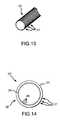
- FIG. 13is an isometric view of a patterned forming tool for forming a sheath in accordance with an alternate embodiment of the invention.
- FIG. 14is an axial cross-sectional view of the patterned forming tool of FIG. 13 engaged with a conforming portion of a sheet of sheath material.
- FIG. 15is an isometric view of a sheet of sheath material engaged with a patterning tool in accordance with another embodiment of the invention.
- FIG. 16is an isometric view of a sheet of sheath material treated with a slip agent and positioned below a forming tool in accordance with yet another embodiment of the invention.
- FIG. 17is an enlarged, partial cross-sectional view of the forming tool engaged with the sheet of sheath material of FIG. 16 taken along line 17 — 17 .
- FIG. 18is an enlarged, partial cross-sectional view of an inner surface treated with the slip agent after engagement with the forming tool of FIG. 17 .
- FIGS. 3-6illustrate a medical device, for example an endoscope 50 having an insertion tube 52 , and a non-extruded, thin-walled, elastic sheath 54 formed in accordance with an embodiment of the invention.
- the elastic sheath 54is shaped and sized so its diameter is slightly larger than the insertion tube's diameter.
- the insertion tube 52can be easily inserted into the elastic sheath 54 until a distal end 56 of the insertion tube 52 just contacts a distal end 58 of the elastic sheath 54 .
- the elastic sheath 54 in FIG. 3is thus in its relaxed state, having a relaxed outside diameter, a relaxed inner diameter, and a relaxed wall thickness.
- the elastic sheath 54has a relaxed wall thickness in the range of up to and including approximately 0.009 inches, and preferably in the range of approximately 0.002 to 0.009 inches, inclusive, and more preferably in the range of approximately 0.002 to 0.006 inches, inclusive.
- FIGS. 4 and 6illustrate the elastic sheath 54 stretched axially over the insertion tube 52 until a proximal end 62 of the elastic sheath 54 aligns with a proximal end 60 of the insertion tube 52 .
- the elastic sheath 54is thus in a stretched, installed position, having a stretched outside diameter, a stretched inner diameter, and stretched wall thickness.
- the stretched inner diameter, stretched outer diameter, and a stretched wall thickness illustrated in FIG. 6are smaller than the similar dimensions relaxed in FIG. 5 .
- the extreme distal end 58 of the elastic sheath 54is sealably connected to an end cap 64 .
- the end cap 64can be integral with the elastic sheath 54 , or can be formed separately from the sheath and sealably attached thereto. In the latter case, the end cap 64 can be formed from a different material than the elastic sheath 54 , such as an inelastic polymer, in order to provide selected optical characteristics that may be different than those of the elastomeric material.
- the end cap 64can be formed from a clear, inelastic polymer to provide better visibility for use with an insertion tube 52 having a viewing window at its distal end 56 .
- the proximal end 62 of the elastic sheath 54terminates in a fitting, such as a collar 66 .
- a fittingsuch as a collar 66 .
- the collar 66can be integral with the sheath 54 or separate from and bonded to the elastic sheath 54 .
- the collar 66is sized and shaped to resiliently engage a headpiece 68 of the endoscope 50 to retain the sheath 54 on the insertion tube 52 during a procedure.
- FIGS. 7 and 8illustrate a method of manufacturing the thin-walled, elastic sheath 54 .
- the methoduses a sheet 70 of elastomeric material, such as a polyurethane, that contains friction-reducing additives or slip agents, such as wax, oil, silicon or silica.
- the sheet 70has an initial thickness of about 0.042 inches, although the thickness of the sheet 70 can vary based on the desired length and thickness of the sheath 54 being formed.
- the sheet 70 of the elastomeric materialis retained on a substantially flat support 72 having a central opening 74 extending therethrough.
- a portion of the elastomeric sheet 70 above the central openingis heated by a conventional heating device to a selected malleable temperature to form a malleable, heated portion 75 of the sheet 70 .
- a forming tool 76is then pressed into the heated portion 75 in a direction substantially normal to the plane of the sheet 70 , illustrated by the direction I.
- the forming tool 76has a generally circular cross-section.
- the forming tool 76could also have an oval, polygonal or other suitable cross-sectional shape.
- the elastomeric sheet 70stretches beyond its modulus of elasticity to form an elongated, thin-walled protrusion 78 (FIG. 8 ).
- the protrusion 78will eventually become all or a portion of the sheath 54 , as the excess material from the elastomeric sheet 70 is trimmed from the protrusion 78 .
- the protrusion 78has an open proximal portion 80 , a closed distal portion 82 spaced away from the open proximal portion 80 , and sidewalls 84 extending between the proximal and distal portions.
- the closed distal portion 82 and the sidewalls 84define an interior 86 of the protrusion 78 .
- the interior 86 of a conforming portion 87 at the distal portion 82 of the protrusion 78begins to closely conform to the outer shape of the forming tool.
- the conforming portion 87 of the protrusion 78progressively conforms to more of the length of the forming tool 75 .
- the forming tool 76is moved in the direction I until the length of the conforming portion 87 of the protrusion 78 is at least as long as the desired length of the elastic sheath 54 being formed.
- the elastic sheath 54can be as long as the insertion tube 52 for which it will be used, or it can be shorter than the insertion tube 52 (FIG. 5) to allow the elastic sheath 54 to be stretched axially over the insertion tube when installed.
- the forming tool 76can be stopped when the conforming portion 87 is at the desired length, or it can be moved further if desired to reduce the thickness of the sidewalls 84 .
- the thickness of the sidewalls 84 in one embodimentis in the range of approximately 0.002 to 0.009 inches, inclusive, and preferably in the range of approximately 0.002 to 0.006 inches, inclusive, or can be thinner than 0.002 inches.
- the forming tool 76is removed from the protrusion 78 and the protrusion is cut to separate the elastic sheath 54 from the elastomeric sheet 70 .
- the distal portion 82 of the protrusion 78can be left on what is now the elastic sheath 54 , or it can be removed and replaced with an end cap 64 (FIG. 6 ). If needed during manufacturing, the sheath 54 can then be trimmed at the distal end to the desired length before attaching the end cap.
- the elastomeric material used with the above embodiment of the present inventionis a thermoplastic, elastomeric material, such as polyurethane containing one or more conventional slip agents, such as wax, oil, silicone or silica.
- slip agentsare commonly used in the field of elastomeric materials, and an individual having ordinary skill in such an art will understand how to treat the elastomeric material to provide the desired properties for reduced friction.
- the treated elastomeric materialallows for small diameter, thin-walled elastic medical components that can be easily, inexpensively, and quickly manufactured.
- Embodiments of the present inventionhave a number of advantages over the sheaths of the prior art and the methods of making such sheaths. Because the elastomeric material is allowed to cool on the forming tool, the forming tool prevents the sheath from collapsing and sticking to itself while the elastomeric material is heated and tacky. This is an improvement over traditional extruded sheaths that could collapse during forming. If the sheath collapsed while the elastomeric material was hot and tacky, the sheath could be ruined.
- the elastic sheath 54is made from an elastomeric material treated with slip agents, the sheath can be formed with a relaxed inner diameter only slightly larger than an outside diameter of the insertion tube 52 and still be easily installed.
- the slip agentsallow the insertion tube to be easily inserted into the elastic sheath 54 without the distal end 56 of the insertion tube 52 binding, catching, or excessively distorting the elastic sheath 54 during installation.
- baggy sheathscan be eliminated.
- the need for additional equipment and features previously used to radially expand the tight-fitting, elastic sheath during installationare also eliminated.
- the elastic sheath 54is made from an elastomeric material, the diameter and wall thickness of the elastic sheath 54 decrease as the sheath is stretched axially over the insertion tube. Accordingly, the overall cross-section of the sheathed insertion tube may be minimized, thereby reducing the pain or discomfort experienced by a patient. Stretching the sheath also creates an axial restoring force in the elastomeric material which retains the end cap 64 at the distal end 58 of the elastic sheath 54 in contact and alignment with the distal end 56 of the insertion tube 52 .
- the elastic sheath 54 and the method of making the sheathare discussed herein with reference to an endoscope 50 , the method of the present invention is equally applicable to other medical components.
- the medical component in alternate embodimentscan be a catheter, optical imaging medical equipment, and non-optical imaging medical equipment.
- FIGS. 9 and 10illustrate an alternate embodiment of the method of the present invention.
- the forming tool 176has a tapered annular portion 177 at a point selected to correspond to a proximal end 180 of the elastic sheath 178 .
- the annular portion 177is provided in this embodiment in order to form an integral collar 185 (FIG. 10) at the sheath's proximal end 180 .
- a radially inward forceis applied to the sidewalls 184 to force the sidewalls against the annular portion 177 .
- the radially inward forceis applied to the sidewalls 184 by a vacuum source (not shown) attached to a vacuum port 179 in the forming tool 176 .
- a partial vacuumis applied to the interior 186 of the sheath 178 via a number of ports 181 in the forming tool 176 .
- a radially inward forceis applied by pressing on the exterior of the sheath's sidewalls.
- the forming tool's annular portion 177has a plurality of passages 190 into which a portion of the sidewalls 184 is drawn when the radially inward force is applied.
- the passages 190are shaped and sized to form retention members 189 in the proximal end 180 of the sheath 178 that releasably engage the distal end of the endoscope control body (not shown).
- the passages 190are shaped into annular grooves extending about the annular portion 177 .
- the retention members 189are formed into annular inward projections.
- the elastic sheath 178is formed with an integral proximal fitting used for retaining the sheath on the endoscope in the installed position.
- the retention members 189are annular in shape and have rectilinear cross-sections. The retention members 189 , however, can have other shapes and sizes.
- the cooled, elastic sheath 178is then removed from the forming tool 176 and the elastic sheath 178 is trimmed or cut near the proximal end 180 to remove excess material from the sheath 178 .
- the sheath's distal end 182may also be trimmed, and an end cap, such as that illustrated in FIGS. 5 and 6, is adhered or otherwise connected to the distal end 182 .
- the sheath's distal end 182extends over the outside of the endcap and is sealably bonded in place.
- the sheath's distal end 182is sealably bonded to the inside of the endcap.
- the sheath 178is then ready for use with an endoscope to perform a selected endoscopic procedure without contaminating the endoscope's insertion tube.
- FIG. 11is an isometric view of a sheet of sheath material 270 positioned below a forming tool 276 in accordance with another embodiment of the invention.
- FIG. 12is an enlarged, partial cross-sectional view of the forming tool 276 of FIG. 11 engaged with the sheet of sheath material 270 .
- the forming tool 276includes a textured portion 277 .
- the sheet of sheath material 270is retained on a support 72 having a central opening 74 as described above. A portion of the sheet of sheath material 270 proximate the central opening 74 is heated to form a malleable heated portion 275 . Alternately, depending upon the material properties of the sheet of sheath material 270 , the entire sheet may be heated.
- the textured portion 277 of the forming tool 276is not smooth. Rather, the textured portion 277 is an uneven, non-smooth portion that includes a plurality of surface features.
- the surface featuresmay be distributed over the textured portion 277 in any desired manner or configuration, including, for example, random spacing, uniform spacing, or non-uniform spacing.
- the surface featuresmay be raised features that project above a nominal surface level of the forming tool 276 , or may be lowered features that project below the nominal surface level (such as, for example, in a porous portion), or may include both raised and lowered features.
- the forming tool 276may be pressed into the heated portion 275 in a direction substantially normal to the plane of the sheet 270 , denoted by the arrow I (FIGS. 11 and 12 ).
- the sheet of sheath material 270stretches to form an elongated portion 278 .
- a conforming portion 287 of the elongated portion 278has an inner surface 279 that contacts the textured portion 277 of the forming tool 276 .
- the inner surface 279may thereby conform and adapt to the textured portion 277 so that the inner surface 279 becomes textured.
- the conforming portion 287may be allowed to cool to a temperature at which the sheet of sheath material 270 is no longer malleable, and the forming tool 276 may be withdrawn from the elongated portion 278 .
- the conforming portion 287may then be processed in the manner set forth above to form an embodiment of a sheath 254 including an elongated, tubular portion having a textured interior surface.
- the sheet of sheath material 270may not be desirable or necessary to cool the sheet of sheath material 270 prior to withdrawing the forming tool 276 .
- the temperature of the sheet of sheath material 270may be partially cooled so that the sheet remains flexible and compliant, but the interior surface 279 retains its texture, as the forming tool 276 is removed.
- mandrels used to form endoscopic sheaths in accordance with the prior arthave surface finishes resulting from ordinary machining operations that may be characterized by a surface roughness average value R of approximately 0.000016 inches (0.4 microns) to 0.000125 inches (3.20 microns).
- the surface roughness average value Ris a standard engineering parameter defined as a number which equals the arithmetical average deviation of the minute surface irregularities from a hypothetical perfect surface (see, for example, Marks' Standard Handbook for Mechanical Engineers, Ninth Edition, p. 13-79). Therefore, the roughness and irregularities of the surfaces of mandrels in accordance with the prior art are approximately imperceptible to the touch and to the unassisted eye.
- the surface features of the textured portion 277 of the forming tool 276are generally perceptible to the touch and to the unassisted eye.
- the size and shape of the surface features of the textured portion 277 (and the textured inner surface 279 )may vary greatly depending upon, for example, the sheath materials used, the size of the sheath, or the intended use of the sheath, in some embodiments, the average heights of the surface features may be approximately 0.005 inches (125 microns) or greater. In a preferred embodiment, the average height or depression of the surface features of the forming tool 276 (and thus the textured inner surface 279 ) is approximately 0.03 inches (0.75 mm). It may be noted that the surface features may vary in height, shape, pattern density, and other characteristics.
- the sheath 254 having a textured interior surfacemay advantageously improve the process of installing and removing the sheath 254 from an endoscopic insertion tube.
- endoscope insertion tubesmay be adversely affected by such factors as reprocessing, operator mishandling, and normal wear which may cause material changes or dimensional changes of the device.
- low durometer (soft) plastic materials used to construct flexible insertion tubeshave been proven to degrade when repeatedly exposed to reprocessing chemicals such as, for example, Glutaraldehyde, hydrogen peroxide, and ethylene oxide. Such chemicals may cause insertion tube materials to crack, swell, and become tacky, making the process of installing and removing a sheath more difficult.
- the sheath 254 having a textured interior surface in accordance with an embodiment of the inventionmay reduce the contact area between the sheath 254 and the insertion tube. Because the contact area is reduced, the friction between the sheath 254 and insertion tube may also be reduced. Consequently, the sheath 254 may be installed and removed more easily and quickly compared with conventional sheaths having a smooth interior surface.
- a methodincludes forming the pressure differential by reducing the pressure within the conforming portion 287 .
- the forming tool 276may be modified to include an integral collar 185 (as shown in FIG. 10) having a plurality of ports 181 fluidly coupled with a vacuum port 179 .
- a vacuum sourcemay be applied to the vacuum port 179 to reduce the pressure within the sheath 254 , creating an inward force that presses the inner surface 279 against the textured portion 277 .
- a pressure vessel 290may be disposed about the conforming portion 287 , and a conforming pressure P may be generated within the pressure vessel 290 , thereby creating an inward force that presses the inner surface 279 against the textured portion 277 .
- a method for forming the sheath 254may include creating a disengagement pressure differential that disengages the textured inner surface 279 from the textured portion 277 .
- the forming tool 276may include the integral collar 185 described above (FIG. 10 ).
- the vacuum port 179may be coupled to a pressure source (e.g., a pump) to increase the pressure within the conforming portion 287 , thereby creating an outward force that drives the inner surface 279 away from the textured portion 277 , thereby disengaging the conforming portion 287 from the forming tool 276 .
- a pressure vessel 290may be disposed about the conforming portion 287 , and a reduced pressure (or “vacuum”) P may be generated within the pressure vessel 290 , thereby creating an outward force that drives the inner surface 279 away from the textured portion 277 .
- FIG. 13is an isometric view of a patterned forming tool 376 for forming a sheath 354 in accordance with an alternate embodiment of the invention.
- FIG. 14is an axial cross-sectional view of the patterned forming tool 376 of FIG. 13 engaged with a conforming portion 387 of a sheet of sheath material 370 .
- the forming tool 376includes an outer surface having a plurality of longitudinal grooves 377 disposed therein. As best shown in FIG. 14, when the forming tool 376 is pressed into a sheet of sheath material 370 , an inner surface 379 of the conforming portion 387 adapts to the grooves 377 so that the inner surface 379 becomes longitudinally grooved. Ridges 389 are thereby formed on the inner surface 379 .
- the conforming portion 387may then be processed as described above to create the sheath 354 having the longitudinally-grooved inner surface 379 .
- patterned forming tool 376is shown in FIGS. 13 and 14 as being patterned with longitudinal grooves 377 , a variety of forming tools featuring a variety of surface patterns may be used. For example, forming tools having spiral grooves, circumferential grooves, crosshatching grooves, pores, dimples, or any other desired pattern may be used. Furthermore, in place of grooves, forming tools having raised features may also be used.
- the method of forming a sheath 354 using a patterned forming tool 376advantageously provides a patterned inner surface 379 which may reduce the friction between the inner surface and the endoscopic insertion tube.
- the ridges 389may contact the outer surface of the insertion tube, thereby reducing the amount of contact area between the sheath 354 and insertion tube. Because the contact area is reduced compared with sheaths having smooth inner walls, the sheath 354 having the patterned inner surface 379 may be more easily installed and removed. Thus, the sheath 354 may be more easily and efficiently installed and removed from the insertion tube, and the user's satisfaction may be increased.
- FIG. 15is an isometric view of a sheet of sheath material 470 engaged with a patterning tool 450 in accordance with another embodiment of the invention.
- the patterning tool 450includes a roller 452 having a plurality of ridges 454 .
- the sheet of sheath material 470may be made malleable or deformable, such as by heating or applying solvents, and the roller 452 may be pressed against the sheet and rolled in a direction R across the face of the sheet.
- the ridges 454press into the sheet and create a plurality of channels 471 in the sheet.
- the sheet of sheath material 470may then be processed according to one of the methods described above to form a sheath 454 having a channeled inner surface 479 .
- a smooth-walled forming tool 76(FIGS. 7 and 8) may be pressed into the sheet of sheath material 470 , forming an elongated portion 478 having the channeled inner surface 479 .
- the sheet of sheath material 470may be patterned using a wide variety of patterning tools, including presses, dies, stamps, lathes, milling machines, or other suitable devices. Also depending upon the material properties of the sheet, and the patterning tool employed, it may not be necessary to make the sheet malleable prior to patterning. For example, an inelastic or plastic material may be patternable using a mill or press without heating the sheet, or otherwise making the sheet malleable.
- the sheet of sheath materialmay be heated to a first temperature for patterning with a patterning tool, and then cooled to a relatively lower temperature for pressing with the forming tool so that the pre-patterned channels on the sheet are not lost during the process of forming the elongated portion 378 .
- sheet materialmay also be patterned or textured by either the calendaring or casting process by which it is originally formed.
- the method of forming the sheath 454 from a pre-patterned sheet of sheath material 470may provide advantages over alternate methods of forming sheaths having patterned inner surfaces. Because the sheet of sheath material is pre-patterned, it may be easier to extract the forming tool from within the conforming portion during manufacture. Because the patterned inner surface 479 is less likely to interlock with the surface of the smooth-walled forming tool 79 (FIG. 7 ), the forming tool 79 may be more easily withdrawn, and the need for applying a disengagement pressure differential may be reduced or eliminated. Thus, because the sheet of sheath material 470 is pre-patterned using the patterning tool 450 , it is less likely that the forming tool will require an integral collar 185 (FIGS.
- the apparatus required to manufacture the sheath 454may be simplified, and the method of manufacture may be more efficient, than alternate methods.
- FIG. 16is an isometric view of a sheet of sheath material 570 treated with a slip agent 572 and positioned below a forming tool 76 in accordance with yet another embodiment of the invention.
- FIG. 17is an enlarged, partial cross-sectional view of the forming tool 76 engaged with the sheet of sheath material 570 of FIG. 16 taken along line 17 — 17 .
- the slip agent 572includes a plurality of granules (or particles) 577 . The granules 577 may be distributed on the surface of the sheet of sheath material 570 .
- the sheet of sheath material 570may be retained on a support 72 having a central opening 74 . A portion of the sheet 570 proximate the central opening 74 is treated (e.g., heated, exposed to solvents, etc.) to form a malleable portion 575 . Alternately, the entire sheet 570 may be treated.
- the forming tool 76may be pressed into the malleable portion 575 in a direction substantially normal to the plane of the sheet 570 , denoted by the arrow I (FIGS. 16 and 17 ).
- the sheet 570stretches to form an elongated portion 578 (FIG. 17 ).
- a conforming portion 587 of the elongated portion 578has an inner surface 579 that presses some of the granules 577 against the forming tool 76 as the forming tool is pressed into the malleable portion 575 of the sheet 570 .
- a textured forming tool 276(FIGS. 11 and 12 ), or a patterned forming tool 376 (FIGS. 13 and 14 ) may be used.
- FIG. 18is an enlarged, partial cross-sectional view of the inner surface 579 treated with the slip agent 572 after engagement with the forming tool 76 of FIG. 17 .
- the granules 577may become partially or wholly embedded into the inner surface 579 . Alternately, some or all of the granules 577 may remain on top of the inner surface 579 .
- the conforming portion 587may be cooled (or otherwise made non-malleable), and the forming tool 76 may be withdrawn from the elongated portion 578 .
- the conforming portion 587may then be processed in the manner set forth above to form an embodiment of a sheath 554 having an interior surface 579 treated with the slip agent 572 .
- powdered or granular slip agents 572may be used, including, for example, cornstarch, silica, materials sold under the trademark TEFLON®, or other suitable materials.
- the granules 577may be partially or wholly embedded in the surface of the sheet 570 prior to engaging the sheet 570 with the forming tool 76 .
- the granules 577may be pressed against the surface of the sheet 570 using a rolling tool (FIG. 15 ), a press, or other suitable device, or may be caste or otherwise integrally formed into the surface during manufacture of the sheet 570 .
- liquid slip agentsmay be used, including, for example, oils, silicone, liquefied wax, or other suitable agents. Such liquid slip agents may remain on top of the inner surface 579 , or may be partially or wholly absorbed into the inner surface 579 during the manufacturing process.
- An advantage of the sheath 554 having an inner surface 579 treated with the slip agent 572is that the process of installing or removing the sheath from an endoscopic insertion tube may be improved.
- the slip agent 572may advantageously reduce the surface friction of the inner surface 579 , allowing the sheath 554 to be slid onto and off of the insertion tube more easily.
- the slip agent 572 having granules 577the granules 577 which become partially embedded within the inner surface 579 may cause the inner surface 579 to remain spaced apart from the outer surface of the insertion tube in the localized area of the embedded granule, reducing the contact area between the inner surface 579 and the insertion tube.
- Loose granules 577 which remain on top of the inner surface 579may also act as spacers which space apart the inner surface 579 from the insertion tube, and may also roll or slide along these respective surfaces, acting as small bearings which further reduce the friction between the inner surface 579 and the insertion tube. Because the sheath 554 may be more easily installed and removed from the insertion tube, medical procedures may be more efficiently conducted, and user satisfaction with the sheath 554 may be improved.
- a vessel 690may be disposed about the conforming portion 587 of the sheet of sheath material 570 .
- the vessel 690may contain a treating agent 692 , such as a slip agent (e.g., oil, silica, wax, cornstarch, etc.), a medication (e.g., an anesthetic, antibiotic, anti-inflammatory, etc.), or any other desired material.
- a slip agente.g., oil, silica, wax, cornstarch, etc.
- a medicatione.g., an anesthetic, antibiotic, anti-inflammatory, etc.
- the vessel 690may be pressurizable so that the treating agent 692 may be pressured to an elevated pressure level P to force the treating agent 692 into contact with the outer surface 580 , as well as to force the inner surface 579 into contact with the slip agent 572 as described above.
- the treating agent 692may be applied to the outer surface 580 prior to engaging the sheet of sheath material 570 with the forming tool 76 , thereby eliminating the vessel 690 .
- the sheath 654 having a treating agent 692 on an outer surface 580may have improved physical or chemical characteristics.
- the treating agent 692may include a slip agent that makes it easier to introduce a sheathed endoscope into a patient's body.
- the treating agent 692may include a medication, such as a topical anesthetic to make the procedure less uncomfortable for the patient, or other various drugs that would treat a medical condition within the patient's body. Therefore, a sheath 654 having a treating agent 692 thereon may provide beneficial results, and may improve the patient's health and satisfaction with the medical procedure.
Landscapes
- Health & Medical Sciences (AREA)
- Life Sciences & Earth Sciences (AREA)
- Surgery (AREA)
- Engineering & Computer Science (AREA)
- Biomedical Technology (AREA)
- Molecular Biology (AREA)
- Pathology (AREA)
- Radiology & Medical Imaging (AREA)
- Nuclear Medicine, Radiotherapy & Molecular Imaging (AREA)
- Biophysics (AREA)
- Physics & Mathematics (AREA)
- Heart & Thoracic Surgery (AREA)
- Medical Informatics (AREA)
- Optics & Photonics (AREA)
- Animal Behavior & Ethology (AREA)
- General Health & Medical Sciences (AREA)
- Public Health (AREA)
- Veterinary Medicine (AREA)
- Mechanical Engineering (AREA)
- Endoscopes (AREA)
- Shaping By String And By Release Of Stress In Plastics And The Like (AREA)
Abstract
Description
Claims (90)
Priority Applications (6)
| Application Number | Priority Date | Filing Date | Title |
|---|---|---|---|
| US09/611,628US6530881B1 (en) | 1999-01-21 | 2000-07-07 | Sheath apparatus for endoscopes and methods for forming same |
| PCT/US2001/007618WO2002007787A2 (en) | 2000-07-07 | 2001-03-08 | Endoscope sheath and method of forming sheath |
| AU2001250818AAU2001250818B9 (en) | 2000-07-07 | 2001-03-08 | Sheath apparatus for endoscopes and methods for forming same |
| JP2002513520AJP4800552B2 (en) | 2000-07-07 | 2001-03-08 | Endoscope sheath and method for forming a sheath |
| AU5081801AAU5081801A (en) | 2000-07-07 | 2001-03-08 | Sheath apparatus for endoscopes and methods for forming same |
| EP01924135.5AEP1581091B1 (en) | 2000-07-07 | 2001-03-08 | Sheath apparatus for endoscopes and methods for forming same |
Applications Claiming Priority (2)
| Application Number | Priority Date | Filing Date | Title |
|---|---|---|---|
| US09/235,355US6350231B1 (en) | 1999-01-21 | 1999-01-21 | Apparatus and method for forming thin-walled elastic components from an elastomeric material |
| US09/611,628US6530881B1 (en) | 1999-01-21 | 2000-07-07 | Sheath apparatus for endoscopes and methods for forming same |
Related Parent Applications (1)
| Application Number | Title | Priority Date | Filing Date |
|---|---|---|---|
| US09/235,355Continuation-In-PartUS6350231B1 (en) | 1999-01-21 | 1999-01-21 | Apparatus and method for forming thin-walled elastic components from an elastomeric material |
Publications (1)
| Publication Number | Publication Date |
|---|---|
| US6530881B1true US6530881B1 (en) | 2003-03-11 |
Family
ID=24449783
Family Applications (1)
| Application Number | Title | Priority Date | Filing Date |
|---|---|---|---|
| US09/611,628Expired - LifetimeUS6530881B1 (en) | 1999-01-21 | 2000-07-07 | Sheath apparatus for endoscopes and methods for forming same |
Country Status (5)
| Country | Link |
|---|---|
| US (1) | US6530881B1 (en) |
| EP (1) | EP1581091B1 (en) |
| JP (1) | JP4800552B2 (en) |
| AU (2) | AU5081801A (en) |
| WO (1) | WO2002007787A2 (en) |
Cited By (94)
| Publication number | Priority date | Publication date | Assignee | Title |
|---|---|---|---|---|
| US20030008083A1 (en)* | 1997-10-10 | 2003-01-09 | Harhen E. Paul | Methods for forming complex-shaped components in a heated polymeric film |
| US20030229269A1 (en)* | 2002-06-05 | 2003-12-11 | Humphrey Robert N. | Scope sleeve |
| US20040039250A1 (en)* | 2002-05-28 | 2004-02-26 | David Tholfsen | Guidewire delivery of implantable bronchial isolation devices in accordance with lung treatment |
| US20040243393A1 (en)* | 2003-05-29 | 2004-12-02 | Microsoft Corporation | Semantic object synchronous understanding implemented with speech application language tags |
| US20050192482A1 (en)* | 2004-01-30 | 2005-09-01 | Endoluminal Therapeutics, Inc. | Disposable sheath for specula |
| US20050283048A1 (en)* | 2001-10-19 | 2005-12-22 | Visionscope, Llc | Portable imaging system employing a miniature endoscope |
| US20060258904A1 (en)* | 2005-05-13 | 2006-11-16 | David Stefanchik | Feeding tube and track |
| US20060258907A1 (en)* | 2005-05-13 | 2006-11-16 | David Stefanchik | Track for medical devices |
| US20060258908A1 (en)* | 2005-05-13 | 2006-11-16 | David Stefanchik | Sheath for use with an endoscope |
| US20060258903A1 (en)* | 2005-05-13 | 2006-11-16 | David Stefanchik | Method of inserting a feeding tube |
| US20060258910A1 (en)* | 2005-05-13 | 2006-11-16 | David Stefanchik | Method of positioning a device on an endoscope |
| US20070167681A1 (en)* | 2001-10-19 | 2007-07-19 | Gill Thomas J | Portable imaging system employing a miniature endoscope |
| US20070185383A1 (en)* | 2006-02-08 | 2007-08-09 | Vision-Sciences, Inc. | Tapered endoscopic protective sheath |
| US20070248141A1 (en)* | 2006-04-21 | 2007-10-25 | Sherwood Services Ag | Infrared thermometer and probe cover thereof |
| US20070270646A1 (en)* | 2006-05-19 | 2007-11-22 | Perry Weiner | Cystoscope and disposable sheath system |
| US20080064925A1 (en)* | 2001-10-19 | 2008-03-13 | Gill Thomas J | Portable imaging system employing a miniature endoscope |
| US7478946B2 (en) | 2003-01-06 | 2009-01-20 | Covidien Ag | Probe cover cassette with improved probe cover support |
| US7556424B2 (en) | 2006-05-19 | 2009-07-07 | Covidien Ag | Tympanic thermometer prove cover cassette and holder |
| US7615005B2 (en) | 2003-05-16 | 2009-11-10 | Ethicon Endo-Surgery, Inc. | Medical apparatus for use with an endoscope |
| US20100041568A1 (en)* | 2006-10-16 | 2010-02-18 | University Of Rochester | Tripodal cyclohexane derivatives and their use as carbohydrate receptors |
| US7686506B2 (en) | 2003-01-06 | 2010-03-30 | Covidien Ag | Stackable tympanic thermometer probe cover cassette |
| US20100199999A1 (en)* | 2009-02-06 | 2010-08-12 | Vazales Brad E | Methods for cleaning endotracheal tubes |
| WO2010066788A3 (en)* | 2008-12-10 | 2010-10-21 | Ambu A/S | Endoscope with a bending portion |
| US7857754B2 (en) | 2005-05-13 | 2010-12-28 | Ethicon Endo-Surgery, Inc. | Apparatus useful for positioning a device on an endoscope |
| US20110023886A1 (en)* | 2009-02-06 | 2011-02-03 | Endoclear, Llc | Medical tube cleaning apparatus |
| US7942814B2 (en) | 2001-10-19 | 2011-05-17 | Visionscope Technologies Llc | Miniature endoscope with imaging fiber system |
| US20110130834A1 (en)* | 2001-10-11 | 2011-06-02 | Pulmonx Corporation | Bronchial flow control devices and methods of use |
| US20110152617A1 (en)* | 2009-12-22 | 2011-06-23 | Tyco Healthcare Group Lp | Endoscope cover fixing device and fixing system |
| US20110282152A1 (en)* | 2010-05-12 | 2011-11-17 | Q Park Medical Limited | Sheath for protecting endoscope probe |
| USRE43745E1 (en) | 2005-11-23 | 2012-10-16 | Tyco Healthcare Group Lp | Tympanic thermometer probe cover with film support mechanism |
| US8317689B1 (en) | 1999-09-13 | 2012-11-27 | Visionscope Technologies Llc | Miniature endoscope system |
| CN103028182A (en)* | 2011-10-04 | 2013-04-10 | 百多力欧洲股份两合公司 | Medical device and guide device therefor |
| US8469880B2 (en) | 2007-02-19 | 2013-06-25 | Ingoscope Systems Gmbh | Tube assembly for an endoscope |
| USD731652S1 (en) | 2014-02-19 | 2015-06-09 | Tidi Products, Llc | Dental curing light sleeve |
| US9101266B2 (en) | 2011-02-07 | 2015-08-11 | Endochoice Innovation Center Ltd. | Multi-element cover for a multi-camera endoscope |
| US9101268B2 (en) | 2009-06-18 | 2015-08-11 | Endochoice Innovation Center Ltd. | Multi-camera endoscope |
| US9101287B2 (en) | 2011-03-07 | 2015-08-11 | Endochoice Innovation Center Ltd. | Multi camera endoscope assembly having multiple working channels |
| WO2015120348A1 (en) | 2014-02-06 | 2015-08-13 | Dentsply International Inc. | Inspection of dental roots and the endodontic cavity space therein |
| WO2015119762A1 (en) | 2014-02-05 | 2015-08-13 | Verathon, Inc. | Cystoscopy system including a catheter endoscope and method of use |
| WO2015187111A1 (en)* | 2014-06-06 | 2015-12-10 | Özkarsli Şükrü Fatih | Protective cover coating device |
| US20160022367A1 (en)* | 2014-07-24 | 2016-01-28 | Fredrick Brody | Minimally invasive lens cleaner |
| US9248266B2 (en) | 2013-12-17 | 2016-02-02 | Biovision Technologies, Llc | Method of performing a sphenopalatine ganglion block procedure |
| CN105307716A (en)* | 2013-05-03 | 2016-02-03 | C·R·巴德公司 | Peelable case |
| US9314147B2 (en) | 2011-12-13 | 2016-04-19 | Endochoice Innovation Center Ltd. | Rotatable connector for an endoscope |
| US9320419B2 (en) | 2010-12-09 | 2016-04-26 | Endochoice Innovation Center Ltd. | Fluid channeling component of a multi-camera endoscope |
| US9386910B2 (en) | 2012-07-18 | 2016-07-12 | Apollo Endosurgery, Inc. | Endoscope overtube for insertion through a natural body orifice |
| US9402533B2 (en) | 2011-03-07 | 2016-08-02 | Endochoice Innovation Center Ltd. | Endoscope circuit board assembly |
| US9433468B2 (en) | 2013-10-04 | 2016-09-06 | Tidi Products, Llc | Sheath for a medical or dental instrument |
| US9445714B2 (en) | 2010-03-29 | 2016-09-20 | Endoclear Llc | Endotracheal tube coupling adapters |
| US9480390B2 (en) | 2008-11-07 | 2016-11-01 | Ashkan Farhadi | Endoscope accessory |
| US9492063B2 (en) | 2009-06-18 | 2016-11-15 | Endochoice Innovation Center Ltd. | Multi-viewing element endoscope |
| US9498108B1 (en) | 2015-04-28 | 2016-11-22 | Opportunity/Discovery Llc | Disposable sheath device |
| US9516995B2 (en) | 2013-12-17 | 2016-12-13 | Biovision Technologies, Llc | Surgical device for performing a sphenopalatine ganglion block procedure |
| US9554692B2 (en) | 2009-06-18 | 2017-01-31 | EndoChoice Innovation Ctr. Ltd. | Multi-camera endoscope |
| US9560953B2 (en) | 2010-09-20 | 2017-02-07 | Endochoice, Inc. | Operational interface in a multi-viewing element endoscope |
| US9560954B2 (en) | 2012-07-24 | 2017-02-07 | Endochoice, Inc. | Connector for use with endoscope |
| US9610005B2 (en) | 2013-07-18 | 2017-04-04 | Ashkan Farhadi | Methods, devices and systems for improved hygiene during endoscopic procedures |
| US9642513B2 (en) | 2009-06-18 | 2017-05-09 | Endochoice Inc. | Compact multi-viewing element endoscope system |
| US9655502B2 (en) | 2011-12-13 | 2017-05-23 | EndoChoice Innovation Center, Ltd. | Removable tip endoscope |
| US9694163B2 (en) | 2013-12-17 | 2017-07-04 | Biovision Technologies, Llc | Surgical device for performing a sphenopalatine ganglion block procedure |
| US9706903B2 (en) | 2009-06-18 | 2017-07-18 | Endochoice, Inc. | Multiple viewing elements endoscope system with modular imaging units |
| US9713417B2 (en) | 2009-06-18 | 2017-07-25 | Endochoice, Inc. | Image capture assembly for use in a multi-viewing elements endoscope |
| US9713415B2 (en) | 2011-03-07 | 2017-07-25 | Endochoice Innovation Center Ltd. | Multi camera endoscope having a side service channel |
| US9814374B2 (en) | 2010-12-09 | 2017-11-14 | Endochoice Innovation Center Ltd. | Flexible electronic circuit board for a multi-camera endoscope |
| US9867529B2 (en) | 2008-11-07 | 2018-01-16 | Izoscope Inc | Endoscope accessory |
| US9872609B2 (en) | 2009-06-18 | 2018-01-23 | Endochoice Innovation Center Ltd. | Multi-camera endoscope |
| US9901244B2 (en) | 2009-06-18 | 2018-02-27 | Endochoice, Inc. | Circuit board assembly of a multiple viewing elements endoscope |
| US9986899B2 (en) | 2013-03-28 | 2018-06-05 | Endochoice, Inc. | Manifold for a multiple viewing elements endoscope |
| US9993142B2 (en) | 2013-03-28 | 2018-06-12 | Endochoice, Inc. | Fluid distribution device for a multiple viewing elements endoscope |
| US10004863B2 (en) | 2012-12-04 | 2018-06-26 | Endoclear Llc | Closed suction cleaning devices, systems and methods |
| US10016575B2 (en) | 2014-06-03 | 2018-07-10 | Endoclear Llc | Cleaning devices, systems and methods |
| US10016580B2 (en) | 2013-12-17 | 2018-07-10 | Biovision Technologies, Llc | Methods for treating sinus diseases |
| US10080486B2 (en) | 2010-09-20 | 2018-09-25 | Endochoice Innovation Center Ltd. | Multi-camera endoscope having fluid channels |
| US10165929B2 (en) | 2009-06-18 | 2019-01-01 | Endochoice, Inc. | Compact multi-viewing element endoscope system |
| US10203493B2 (en) | 2010-10-28 | 2019-02-12 | Endochoice Innovation Center Ltd. | Optical systems for multi-sensor endoscopes |
| US10307042B2 (en) | 2015-04-28 | 2019-06-04 | Opportunity/Discovery Llc | Disposable sheath device |
| US10389921B2 (en) | 2015-08-31 | 2019-08-20 | Panasonic Corporation | Endoscope |
| US10456164B2 (en) | 2017-10-02 | 2019-10-29 | URO-1, Inc. | Anti-microbial medical injection assemblies for onabotulinumtoxina delivery and methods of use thereof |
| US10499794B2 (en) | 2013-05-09 | 2019-12-10 | Endochoice, Inc. | Operational interface in a multi-viewing element endoscope |
| US10525240B1 (en) | 2018-06-28 | 2020-01-07 | Sandler Scientific LLC | Sino-nasal rinse delivery device with agitation, flow-control and integrated medication management system |
| US10709317B2 (en)* | 2018-10-04 | 2020-07-14 | PraesidioDyne, LLC | Clamp assembly for disposable endoscopic sheaths |
| US10722322B2 (en) | 2010-03-29 | 2020-07-28 | Endoclear Llc | Distal airway cleaning devices |
| CN111918596A (en)* | 2018-03-30 | 2020-11-10 | 夏普株式会社 | Endoscope distal end portion cover and endoscope |
| US20210127952A1 (en)* | 2017-08-01 | 2021-05-06 | Seed Co., Ltd. | Endoscope hood |
| US11278190B2 (en) | 2009-06-18 | 2022-03-22 | Endochoice, Inc. | Multi-viewing element endoscope |
| US11389627B1 (en) | 2018-10-02 | 2022-07-19 | Lutonix Inc. | Balloon protectors, balloon-catheter assemblies, and methods thereof |
| US11547275B2 (en) | 2009-06-18 | 2023-01-10 | Endochoice, Inc. | Compact multi-viewing element endoscope system |
| US11559189B2 (en)* | 2018-10-31 | 2023-01-24 | Carl Zeiss Meditec Ag | Sterile sheath for confocal endomicroscopy scanner probe |
| US11864734B2 (en) | 2009-06-18 | 2024-01-09 | Endochoice, Inc. | Multi-camera endoscope |
| US11889986B2 (en) | 2010-12-09 | 2024-02-06 | Endochoice, Inc. | Flexible electronic circuit board for a multi-camera endoscope |
| US12070188B2 (en) | 2018-10-10 | 2024-08-27 | Sharp Kabushiki Kaisha | Endoscope tip cover and endoscope |
| US12137873B2 (en) | 2009-06-18 | 2024-11-12 | Endochoice, Inc. | Compact multi-viewing element endoscope system |
| US12204087B2 (en) | 2010-10-28 | 2025-01-21 | Endochoice, Inc. | Optical systems for multi-sensor endoscopes |
| US12220105B2 (en) | 2010-06-16 | 2025-02-11 | Endochoice, Inc. | Circuit board assembly of a multiple viewing elements endoscope |
Families Citing this family (2)
| Publication number | Priority date | Publication date | Assignee | Title |
|---|---|---|---|---|
| GB0718093D0 (en)* | 2007-09-17 | 2007-10-24 | Park Medical Ltd Q | Sheath assembly |
| EP4344601A1 (en)* | 2022-09-28 | 2024-04-03 | Ambu A/S | Endoscope comprising a friction-reducing working channel tube |
Citations (25)
| Publication number | Priority date | Publication date | Assignee | Title |
|---|---|---|---|---|
| US3794091A (en) | 1971-10-07 | 1974-02-26 | Med General Inc | Sterile sheath for surgical illuminator |
| US3805770A (en)* | 1971-07-22 | 1974-04-23 | Olympus Optical Co | Endoscope guide and lubricating means |
| US3809072A (en) | 1971-10-07 | 1974-05-07 | Med General Inc | Sterile sheath apparatus for fiber optic illuminator with compatible lens |
| US4143423A (en)* | 1977-10-25 | 1979-03-13 | Sternlieb Jack J | Surgical lubricants |
| US4794920A (en)* | 1987-07-14 | 1989-01-03 | Robichaud David M | Birth control device |
| US4881553A (en)* | 1987-11-20 | 1989-11-21 | Grossman Richard A | Mesh reinforced condom |
| US4886049A (en) | 1988-05-17 | 1989-12-12 | Darras Robert L | Medical instrument cover |
| US4971071A (en)* | 1989-07-14 | 1990-11-20 | Stanley Hochfeld | Conductive condom |
| US5098755A (en)* | 1990-11-21 | 1992-03-24 | Tanquary Albert C | Textured thermoplastic elastomeric film, articles comprising same, and method of making such textured thermoplastic elastomeric film and articles |
| US5111831A (en)* | 1990-02-16 | 1992-05-12 | Foggia David J | Scrotum supporting condom with retention means |
| US5237984A (en) | 1991-06-24 | 1993-08-24 | Xomed-Treace Inc. | Sheath for endoscope |
| US5337734A (en)* | 1992-10-29 | 1994-08-16 | Advanced Polymers, Incorporated | Disposable sheath with optically transparent window formed continuously integral therewith |
| US5419310A (en) | 1992-11-03 | 1995-05-30 | Vision Sciences, Inc. | Partially inflated protective endoscope sheath |
| US5429118A (en)* | 1994-04-07 | 1995-07-04 | Cook (Canada) Incorporated | Disposable medical scope sheath |
| US5482053A (en)* | 1989-06-06 | 1996-01-09 | Kelly; Patrick D. | Condom lubricants containing zinc as an anti-viral agent |
| US5483951A (en) | 1994-02-25 | 1996-01-16 | Vision-Sciences, Inc. | Working channels for a disposable sheath for an endoscope |
| US5505686A (en) | 1994-05-05 | 1996-04-09 | Imagyn Medical, Inc. | Endoscope with protruding member and method of utilizing the same |
| US5513654A (en)* | 1994-06-10 | 1996-05-07 | New Designs Corporation | Slip-resistant contraceptive male condom |
| US5570692A (en)* | 1995-05-19 | 1996-11-05 | Hayashi Denki Co. Ltd. | Ultrasonic doppler blood flow detector for hemorrhoid artery ligation |
| US5643175A (en) | 1992-09-01 | 1997-07-01 | Adair; Edwin L. | Sterilizable endoscope with separable disposable tube assembly |
| US5695454A (en) | 1994-06-30 | 1997-12-09 | Mourkidou; Sotiria | Cover for a laryngoscope |
| US5718861A (en) | 1993-12-20 | 1998-02-17 | C. R. Bard, Incorporated | Method of forming intra-aortic balloon catheters |
| US5881386A (en)* | 1993-12-23 | 1999-03-16 | Maxxim Medical, Inc. | Flexible polyvinyl chloride article and method of making |
| US6270484B1 (en)* | 1999-02-17 | 2001-08-07 | Inbae Yoon | Safety penetrating instrument with expandible portion and method of penetrating anatomical cavity |
| US6293907B1 (en)* | 1996-05-23 | 2001-09-25 | Anthony Thomas Roger Axon | Endoscope cover having protrusions |
Family Cites Families (6)
| Publication number | Priority date | Publication date | Assignee | Title |
|---|---|---|---|---|
| US4840188A (en)* | 1988-01-11 | 1989-06-20 | Heidenfelder Herbert J | Desensitizing condom |
| JP3421038B2 (en)* | 1992-09-01 | 2003-06-30 | エドウィン エル アデアー, | Sterilizable endoscope having a detachable disposable tube assembly |
| US5279317A (en)* | 1993-02-26 | 1994-01-18 | Bowman Michael D | Endoscopic cannulated instrument flushing apparatus for forcing a cleaning solution through an endoscopic cannulated instrument for removal of gross debris |
| SE9401620L (en)* | 1994-05-10 | 1996-01-10 | Alpharma Ab | Combined use of local anesthetics and dressings |
| US5569159A (en)* | 1994-12-16 | 1996-10-29 | Anderson; Keven C. | Endoscopic sleeve |
| US5989567A (en)* | 1997-12-31 | 1999-11-23 | Dolisi; Frank | Method and device for infant male circumcision anesthesia |
- 2000
- 2000-07-07USUS09/611,628patent/US6530881B1/ennot_activeExpired - Lifetime
- 2001
- 2001-03-08AUAU5081801Apatent/AU5081801A/enactivePending
- 2001-03-08EPEP01924135.5Apatent/EP1581091B1/ennot_activeExpired - Lifetime
- 2001-03-08AUAU2001250818Apatent/AU2001250818B9/ennot_activeExpired
- 2001-03-08JPJP2002513520Apatent/JP4800552B2/ennot_activeExpired - Lifetime
- 2001-03-08WOPCT/US2001/007618patent/WO2002007787A2/enactiveIP Right Grant
Patent Citations (26)
| Publication number | Priority date | Publication date | Assignee | Title |
|---|---|---|---|---|
| US3805770A (en)* | 1971-07-22 | 1974-04-23 | Olympus Optical Co | Endoscope guide and lubricating means |
| US3794091A (en) | 1971-10-07 | 1974-02-26 | Med General Inc | Sterile sheath for surgical illuminator |
| US3809072A (en) | 1971-10-07 | 1974-05-07 | Med General Inc | Sterile sheath apparatus for fiber optic illuminator with compatible lens |
| US4143423A (en)* | 1977-10-25 | 1979-03-13 | Sternlieb Jack J | Surgical lubricants |
| US4794920A (en)* | 1987-07-14 | 1989-01-03 | Robichaud David M | Birth control device |
| US4881553A (en)* | 1987-11-20 | 1989-11-21 | Grossman Richard A | Mesh reinforced condom |
| US4886049A (en) | 1988-05-17 | 1989-12-12 | Darras Robert L | Medical instrument cover |
| US5482053A (en)* | 1989-06-06 | 1996-01-09 | Kelly; Patrick D. | Condom lubricants containing zinc as an anti-viral agent |
| US4971071A (en)* | 1989-07-14 | 1990-11-20 | Stanley Hochfeld | Conductive condom |
| US5111831A (en)* | 1990-02-16 | 1992-05-12 | Foggia David J | Scrotum supporting condom with retention means |
| US5098755A (en)* | 1990-11-21 | 1992-03-24 | Tanquary Albert C | Textured thermoplastic elastomeric film, articles comprising same, and method of making such textured thermoplastic elastomeric film and articles |
| US5237984A (en) | 1991-06-24 | 1993-08-24 | Xomed-Treace Inc. | Sheath for endoscope |
| US5643175A (en) | 1992-09-01 | 1997-07-01 | Adair; Edwin L. | Sterilizable endoscope with separable disposable tube assembly |
| US5337734A (en)* | 1992-10-29 | 1994-08-16 | Advanced Polymers, Incorporated | Disposable sheath with optically transparent window formed continuously integral therewith |
| US5443781A (en) | 1992-10-29 | 1995-08-22 | Saab; Mark A. | Method of preparing disposable sheath with optically transparent windows formed continuously integral therewith |
| US5419310A (en) | 1992-11-03 | 1995-05-30 | Vision Sciences, Inc. | Partially inflated protective endoscope sheath |
| US5718861A (en) | 1993-12-20 | 1998-02-17 | C. R. Bard, Incorporated | Method of forming intra-aortic balloon catheters |
| US5881386A (en)* | 1993-12-23 | 1999-03-16 | Maxxim Medical, Inc. | Flexible polyvinyl chloride article and method of making |
| US5483951A (en) | 1994-02-25 | 1996-01-16 | Vision-Sciences, Inc. | Working channels for a disposable sheath for an endoscope |
| US5429118A (en)* | 1994-04-07 | 1995-07-04 | Cook (Canada) Incorporated | Disposable medical scope sheath |
| US5505686A (en) | 1994-05-05 | 1996-04-09 | Imagyn Medical, Inc. | Endoscope with protruding member and method of utilizing the same |
| US5513654A (en)* | 1994-06-10 | 1996-05-07 | New Designs Corporation | Slip-resistant contraceptive male condom |
| US5695454A (en) | 1994-06-30 | 1997-12-09 | Mourkidou; Sotiria | Cover for a laryngoscope |
| US5570692A (en)* | 1995-05-19 | 1996-11-05 | Hayashi Denki Co. Ltd. | Ultrasonic doppler blood flow detector for hemorrhoid artery ligation |
| US6293907B1 (en)* | 1996-05-23 | 2001-09-25 | Anthony Thomas Roger Axon | Endoscope cover having protrusions |
| US6270484B1 (en)* | 1999-02-17 | 2001-08-07 | Inbae Yoon | Safety penetrating instrument with expandible portion and method of penetrating anatomical cavity |
Cited By (181)
| Publication number | Priority date | Publication date | Assignee | Title |
|---|---|---|---|---|
| US7025923B2 (en)* | 1997-10-10 | 2006-04-11 | Vision Sciences, Inc. | Methods for forming complex-shaped components in a heated polymeric film |
| US20030008083A1 (en)* | 1997-10-10 | 2003-01-09 | Harhen E. Paul | Methods for forming complex-shaped components in a heated polymeric film |
| US8317689B1 (en) | 1999-09-13 | 2012-11-27 | Visionscope Technologies Llc | Miniature endoscope system |
| US20110130834A1 (en)* | 2001-10-11 | 2011-06-02 | Pulmonx Corporation | Bronchial flow control devices and methods of use |
| US11484189B2 (en) | 2001-10-19 | 2022-11-01 | Visionscope Technologies Llc | Portable imaging system employing a miniature endoscope |
| US20050283048A1 (en)* | 2001-10-19 | 2005-12-22 | Visionscope, Llc | Portable imaging system employing a miniature endoscope |
| US20080064925A1 (en)* | 2001-10-19 | 2008-03-13 | Gill Thomas J | Portable imaging system employing a miniature endoscope |
| US8038602B2 (en) | 2001-10-19 | 2011-10-18 | Visionscope Llc | Portable imaging system employing a miniature endoscope |
| US10595710B2 (en) | 2001-10-19 | 2020-03-24 | Visionscope Technologies Llc | Portable imaging system employing a miniature endoscope |
| US7942814B2 (en) | 2001-10-19 | 2011-05-17 | Visionscope Technologies Llc | Miniature endoscope with imaging fiber system |
| US20070167681A1 (en)* | 2001-10-19 | 2007-07-19 | Gill Thomas J | Portable imaging system employing a miniature endoscope |
| US20050066974A1 (en)* | 2002-05-28 | 2005-03-31 | Antony Fields | Modification of lung region flow dynamics using flow control devices implanted in bronchial wall channels |
| US20040039250A1 (en)* | 2002-05-28 | 2004-02-26 | David Tholfsen | Guidewire delivery of implantable bronchial isolation devices in accordance with lung treatment |
| US20030229269A1 (en)* | 2002-06-05 | 2003-12-11 | Humphrey Robert N. | Scope sleeve |
| US7927012B2 (en) | 2003-01-06 | 2011-04-19 | Covidien Ag | Probe cover cassette with improved probe cover support |
| US7686506B2 (en) | 2003-01-06 | 2010-03-30 | Covidien Ag | Stackable tympanic thermometer probe cover cassette |
| US7478946B2 (en) | 2003-01-06 | 2009-01-20 | Covidien Ag | Probe cover cassette with improved probe cover support |
| US7615005B2 (en) | 2003-05-16 | 2009-11-10 | Ethicon Endo-Surgery, Inc. | Medical apparatus for use with an endoscope |
| US20040243393A1 (en)* | 2003-05-29 | 2004-12-02 | Microsoft Corporation | Semantic object synchronous understanding implemented with speech application language tags |
| US20050192482A1 (en)* | 2004-01-30 | 2005-09-01 | Endoluminal Therapeutics, Inc. | Disposable sheath for specula |
| US20060258903A1 (en)* | 2005-05-13 | 2006-11-16 | David Stefanchik | Method of inserting a feeding tube |
| US7905830B2 (en)* | 2005-05-13 | 2011-03-15 | Ethicon Endo-Surgery, Inc. | Sheath for use with an endoscope |
| US20060258904A1 (en)* | 2005-05-13 | 2006-11-16 | David Stefanchik | Feeding tube and track |
| US20060258907A1 (en)* | 2005-05-13 | 2006-11-16 | David Stefanchik | Track for medical devices |
| US7615003B2 (en) | 2005-05-13 | 2009-11-10 | Ethicon Endo-Surgery, Inc. | Track for medical devices |
| US7648457B2 (en) | 2005-05-13 | 2010-01-19 | Ethicon Endo-Surgery, Inc. | Method of positioning a device on an endoscope |
| US20060258908A1 (en)* | 2005-05-13 | 2006-11-16 | David Stefanchik | Sheath for use with an endoscope |
| US20060258910A1 (en)* | 2005-05-13 | 2006-11-16 | David Stefanchik | Method of positioning a device on an endoscope |
| US7857754B2 (en) | 2005-05-13 | 2010-12-28 | Ethicon Endo-Surgery, Inc. | Apparatus useful for positioning a device on an endoscope |
| USRE43745E1 (en) | 2005-11-23 | 2012-10-16 | Tyco Healthcare Group Lp | Tympanic thermometer probe cover with film support mechanism |
| US20070185383A1 (en)* | 2006-02-08 | 2007-08-09 | Vision-Sciences, Inc. | Tapered endoscopic protective sheath |
| US20080089387A1 (en)* | 2006-04-21 | 2008-04-17 | Sherwood Services Ag | Probe Cover Having a Blackbody |
| US20070248141A1 (en)* | 2006-04-21 | 2007-10-25 | Sherwood Services Ag | Infrared thermometer and probe cover thereof |
| US7530738B2 (en) | 2006-04-21 | 2009-05-12 | Covidien Ag | Probe cover having a blackbody |
| US20090185598A1 (en)* | 2006-04-21 | 2009-07-23 | Tyco Healthcare Group Lp | Probe cover having a blackbody |
| US8123401B2 (en) | 2006-04-21 | 2012-02-28 | Covidien Ag | Probe cover having a blackbody |
| US20070270646A1 (en)* | 2006-05-19 | 2007-11-22 | Perry Weiner | Cystoscope and disposable sheath system |
| US7556424B2 (en) | 2006-05-19 | 2009-07-07 | Covidien Ag | Tympanic thermometer prove cover cassette and holder |
| US20100041568A1 (en)* | 2006-10-16 | 2010-02-18 | University Of Rochester | Tripodal cyclohexane derivatives and their use as carbohydrate receptors |
| US9931019B2 (en) | 2007-02-19 | 2018-04-03 | Ingoscope Systems Gmbh | Tube assembly for an endoscope |
| US8469880B2 (en) | 2007-02-19 | 2013-06-25 | Ingoscope Systems Gmbh | Tube assembly for an endoscope |
| US9480390B2 (en) | 2008-11-07 | 2016-11-01 | Ashkan Farhadi | Endoscope accessory |
| US9867529B2 (en) | 2008-11-07 | 2018-01-16 | Izoscope Inc | Endoscope accessory |
| WO2010066788A3 (en)* | 2008-12-10 | 2010-10-21 | Ambu A/S | Endoscope with a bending portion |
| US20110023886A1 (en)* | 2009-02-06 | 2011-02-03 | Endoclear, Llc | Medical tube cleaning apparatus |
| US8157919B2 (en) | 2009-02-06 | 2012-04-17 | Endoclear, Llc | Methods for removing debris from medical tubes |
| US10682203B2 (en) | 2009-02-06 | 2020-06-16 | Endoclear Llc | Methods of cleaning endotracheal tubes including light treatment |
| US8381345B2 (en) | 2009-02-06 | 2013-02-26 | Endoclear, Llc | Devices for cleaning endotracheal tubes |
| US8382908B2 (en) | 2009-02-06 | 2013-02-26 | Endoclear, Llc | Methods for cleaning endotracheal tubes |
| US20110023887A1 (en)* | 2009-02-06 | 2011-02-03 | Endoclear, Llc | Methods for tracheostomy visualization |
| US8458844B2 (en) | 2009-02-06 | 2013-06-11 | Endoclear, Llc | Medical tube cleaning apparatus |
| US8468637B2 (en) | 2009-02-06 | 2013-06-25 | Endoclear Llc | Mechanically-actuated endotracheal tube cleaning device |
| US20110023885A1 (en)* | 2009-02-06 | 2011-02-03 | Endoclear, Llc | Mechanically-actuated endotracheal tube cleaning device |
| US8534287B2 (en) | 2009-02-06 | 2013-09-17 | Endoclear, Llc | Methods for tracheostomy visualization |
| US8601633B2 (en) | 2009-02-06 | 2013-12-10 | Endoclear Llc | Cleaning of body-inserted medical tubes |
| US20110023888A1 (en)* | 2009-02-06 | 2011-02-03 | Endoclear, Llc | Methods for removing debris from medical tubes |
| US9095286B2 (en) | 2009-02-06 | 2015-08-04 | Endoclear Llc | Body-inserted tube cleaning |
| US10441380B2 (en) | 2009-02-06 | 2019-10-15 | Endoclear Llc | Body-inserted tube cleaning |
| US9962233B2 (en) | 2009-02-06 | 2018-05-08 | Endoclear Llc | Body-inserted tube cleaning |
| US9332891B2 (en) | 2009-02-06 | 2016-05-10 | Endoclear Llc | Tracheostomy visualization |
| US9907624B2 (en) | 2009-02-06 | 2018-03-06 | Endoclear Llc | Body-inserted tube cleaning with suction |
| US20100199448A1 (en)* | 2009-02-06 | 2010-08-12 | Endoclear, Llc | Devices for cleaning endotracheal tubes |
| US9855111B2 (en) | 2009-02-06 | 2018-01-02 | Endoclear Llc | Methods of removing biofilm from endotracheal tubes |
| US9579012B2 (en) | 2009-02-06 | 2017-02-28 | Endoclear Llc | Visualized endotracheal tube placement systems |
| US20100199999A1 (en)* | 2009-02-06 | 2010-08-12 | Vazales Brad E | Methods for cleaning endotracheal tubes |
| US9398837B2 (en) | 2009-02-06 | 2016-07-26 | Endoclear Llc | Methods for confirming placement of endotracheal tubes |
| US9386907B2 (en) | 2009-02-06 | 2016-07-12 | Endoclear Llc | Visualization systems and methods |
| US10638922B2 (en) | 2009-06-18 | 2020-05-05 | Endochoice, Inc. | Multi-camera endoscope |
| US12303106B2 (en) | 2009-06-18 | 2025-05-20 | Endochoice, Inc. | Multi-camera endoscope |
| US10912445B2 (en) | 2009-06-18 | 2021-02-09 | Endochoice, Inc. | Compact multi-viewing element endoscope system |
| US10799095B2 (en) | 2009-06-18 | 2020-10-13 | Endochoice, Inc. | Multi-viewing element endoscope |
| US10791910B2 (en) | 2009-06-18 | 2020-10-06 | Endochoice, Inc. | Multiple viewing elements endoscope system with modular imaging units |
| US10791909B2 (en) | 2009-06-18 | 2020-10-06 | Endochoice, Inc. | Image capture assembly for use in a multi-viewing elements endoscope |
| US10765305B2 (en) | 2009-06-18 | 2020-09-08 | Endochoice, Inc. | Circuit board assembly of a multiple viewing elements endoscope |
| US9872609B2 (en) | 2009-06-18 | 2018-01-23 | Endochoice Innovation Center Ltd. | Multi-camera endoscope |
| US12137873B2 (en) | 2009-06-18 | 2024-11-12 | Endochoice, Inc. | Compact multi-viewing element endoscope system |
| US11278190B2 (en) | 2009-06-18 | 2022-03-22 | Endochoice, Inc. | Multi-viewing element endoscope |
| US9901244B2 (en) | 2009-06-18 | 2018-02-27 | Endochoice, Inc. | Circuit board assembly of a multiple viewing elements endoscope |
| US12336686B2 (en) | 2009-06-18 | 2025-06-24 | Endochoice, Inc. | Multi-viewing element endoscope |
| US9492063B2 (en) | 2009-06-18 | 2016-11-15 | Endochoice Innovation Center Ltd. | Multi-viewing element endoscope |
| US10905320B2 (en) | 2009-06-18 | 2021-02-02 | Endochoice, Inc. | Multi-camera endoscope |
| US11471028B2 (en) | 2009-06-18 | 2022-10-18 | Endochoice, Inc. | Circuit board assembly of a multiple viewing elements endoscope |
| US11986155B2 (en) | 2009-06-18 | 2024-05-21 | Endochoice, Inc. | Multi-viewing element endoscope |
| US9554692B2 (en) | 2009-06-18 | 2017-01-31 | EndoChoice Innovation Ctr. Ltd. | Multi-camera endoscope |
| US11534056B2 (en) | 2009-06-18 | 2022-12-27 | Endochoice, Inc. | Multi-camera endoscope |
| US10165929B2 (en) | 2009-06-18 | 2019-01-01 | Endochoice, Inc. | Compact multi-viewing element endoscope system |
| US9101268B2 (en) | 2009-06-18 | 2015-08-11 | Endochoice Innovation Center Ltd. | Multi-camera endoscope |
| US10092167B2 (en) | 2009-06-18 | 2018-10-09 | Endochoice, Inc. | Multiple viewing elements endoscope system with modular imaging units |
| US9642513B2 (en) | 2009-06-18 | 2017-05-09 | Endochoice Inc. | Compact multi-viewing element endoscope system |
| US11547275B2 (en) | 2009-06-18 | 2023-01-10 | Endochoice, Inc. | Compact multi-viewing element endoscope system |
| US11864734B2 (en) | 2009-06-18 | 2024-01-09 | Endochoice, Inc. | Multi-camera endoscope |
| US9706903B2 (en) | 2009-06-18 | 2017-07-18 | Endochoice, Inc. | Multiple viewing elements endoscope system with modular imaging units |
| US9706905B2 (en) | 2009-06-18 | 2017-07-18 | Endochoice Innovation Center Ltd. | Multi-camera endoscope |
| US9713417B2 (en) | 2009-06-18 | 2017-07-25 | Endochoice, Inc. | Image capture assembly for use in a multi-viewing elements endoscope |
| US20110152617A1 (en)* | 2009-12-22 | 2011-06-23 | Tyco Healthcare Group Lp | Endoscope cover fixing device and fixing system |
| US9445714B2 (en) | 2010-03-29 | 2016-09-20 | Endoclear Llc | Endotracheal tube coupling adapters |
| US10722322B2 (en) | 2010-03-29 | 2020-07-28 | Endoclear Llc | Distal airway cleaning devices |
| US20110282152A1 (en)* | 2010-05-12 | 2011-11-17 | Q Park Medical Limited | Sheath for protecting endoscope probe |
| US12220105B2 (en) | 2010-06-16 | 2025-02-11 | Endochoice, Inc. | Circuit board assembly of a multiple viewing elements endoscope |
| US9986892B2 (en) | 2010-09-20 | 2018-06-05 | Endochoice, Inc. | Operational interface in a multi-viewing element endoscope |
| US10080486B2 (en) | 2010-09-20 | 2018-09-25 | Endochoice Innovation Center Ltd. | Multi-camera endoscope having fluid channels |
| US9560953B2 (en) | 2010-09-20 | 2017-02-07 | Endochoice, Inc. | Operational interface in a multi-viewing element endoscope |
| US11543646B2 (en) | 2010-10-28 | 2023-01-03 | Endochoice, Inc. | Optical systems for multi-sensor endoscopes |
| US12204087B2 (en) | 2010-10-28 | 2025-01-21 | Endochoice, Inc. | Optical systems for multi-sensor endoscopes |
| US10203493B2 (en) | 2010-10-28 | 2019-02-12 | Endochoice Innovation Center Ltd. | Optical systems for multi-sensor endoscopes |
| US11497388B2 (en) | 2010-12-09 | 2022-11-15 | Endochoice, Inc. | Flexible electronic circuit board for a multi-camera endoscope |
| US9814374B2 (en) | 2010-12-09 | 2017-11-14 | Endochoice Innovation Center Ltd. | Flexible electronic circuit board for a multi-camera endoscope |
| US11889986B2 (en) | 2010-12-09 | 2024-02-06 | Endochoice, Inc. | Flexible electronic circuit board for a multi-camera endoscope |
| US10182707B2 (en) | 2010-12-09 | 2019-01-22 | Endochoice Innovation Center Ltd. | Fluid channeling component of a multi-camera endoscope |
| US10898063B2 (en) | 2010-12-09 | 2021-01-26 | Endochoice, Inc. | Flexible electronic circuit board for a multi camera endoscope |
| US9320419B2 (en) | 2010-12-09 | 2016-04-26 | Endochoice Innovation Center Ltd. | Fluid channeling component of a multi-camera endoscope |
| US9101266B2 (en) | 2011-02-07 | 2015-08-11 | Endochoice Innovation Center Ltd. | Multi-element cover for a multi-camera endoscope |
| US9351629B2 (en) | 2011-02-07 | 2016-05-31 | Endochoice Innovation Center Ltd. | Multi-element cover for a multi-camera endoscope |
| US10070774B2 (en) | 2011-02-07 | 2018-09-11 | Endochoice Innovation Center Ltd. | Multi-element cover for a multi-camera endoscope |
| US9402533B2 (en) | 2011-03-07 | 2016-08-02 | Endochoice Innovation Center Ltd. | Endoscope circuit board assembly |
| US9854959B2 (en) | 2011-03-07 | 2018-01-02 | Endochoice Innovation Center Ltd. | Multi camera endoscope assembly having multiple working channels |
| US10292578B2 (en) | 2011-03-07 | 2019-05-21 | Endochoice Innovation Center Ltd. | Multi camera endoscope assembly having multiple working channels |
| US9713415B2 (en) | 2011-03-07 | 2017-07-25 | Endochoice Innovation Center Ltd. | Multi camera endoscope having a side service channel |
| US9101287B2 (en) | 2011-03-07 | 2015-08-11 | Endochoice Innovation Center Ltd. | Multi camera endoscope assembly having multiple working channels |
| US11026566B2 (en) | 2011-03-07 | 2021-06-08 | Endochoice, Inc. | Multi camera endoscope assembly having multiple working channels |
| CN103028182B (en)* | 2011-10-04 | 2016-06-01 | 百多力欧洲股份两合公司 | Medical treatment device and guide arrangement thereof |
| CN103028182A (en)* | 2011-10-04 | 2013-04-10 | 百多力欧洲股份两合公司 | Medical device and guide device therefor |
| US9655502B2 (en) | 2011-12-13 | 2017-05-23 | EndoChoice Innovation Center, Ltd. | Removable tip endoscope |
| US12290241B2 (en) | 2011-12-13 | 2025-05-06 | Endochoice, Inc. | Removable tip endoscope |
| US11291357B2 (en) | 2011-12-13 | 2022-04-05 | Endochoice, Inc. | Removable tip endoscope |
| US9314147B2 (en) | 2011-12-13 | 2016-04-19 | Endochoice Innovation Center Ltd. | Rotatable connector for an endoscope |
| US10470649B2 (en) | 2011-12-13 | 2019-11-12 | Endochoice, Inc. | Removable tip endoscope |
| US9386910B2 (en) | 2012-07-18 | 2016-07-12 | Apollo Endosurgery, Inc. | Endoscope overtube for insertion through a natural body orifice |
| US9560954B2 (en) | 2012-07-24 | 2017-02-07 | Endochoice, Inc. | Connector for use with endoscope |
| US11173266B2 (en) | 2012-12-04 | 2021-11-16 | Endoclear Llc | Closed suction cleaning devices, systems and methods |
| US10004863B2 (en) | 2012-12-04 | 2018-06-26 | Endoclear Llc | Closed suction cleaning devices, systems and methods |
| US10821249B2 (en) | 2012-12-04 | 2020-11-03 | Endoclear Llc | Closed suction cleaning devices, systems and methods |
| US11793393B2 (en) | 2013-03-28 | 2023-10-24 | Endochoice, Inc. | Manifold for a multiple viewing elements endoscope |
| US9993142B2 (en) | 2013-03-28 | 2018-06-12 | Endochoice, Inc. | Fluid distribution device for a multiple viewing elements endoscope |
| US10905315B2 (en) | 2013-03-28 | 2021-02-02 | Endochoice, Inc. | Manifold for a multiple viewing elements endoscope |
| US11925323B2 (en) | 2013-03-28 | 2024-03-12 | Endochoice, Inc. | Fluid distribution device for a multiple viewing elements endoscope |
| US9986899B2 (en) | 2013-03-28 | 2018-06-05 | Endochoice, Inc. | Manifold for a multiple viewing elements endoscope |
| US10925471B2 (en) | 2013-03-28 | 2021-02-23 | Endochoice, Inc. | Fluid distribution device for a multiple viewing elements endoscope |
| US12232699B2 (en) | 2013-03-28 | 2025-02-25 | Endochoice, Inc. | Manifold for a multiple viewing elements endoscope |
| US20160058983A1 (en)* | 2013-05-03 | 2016-03-03 | C.R. Bard, Inc. | Peelable Protective Sheath |
| AU2014262160B2 (en)* | 2013-05-03 | 2018-12-13 | C.R. Bard, Inc. | Peelable protective sheath |
| CN105307716B (en)* | 2013-05-03 | 2021-09-14 | C·R·巴德公司 | Strippable protective sleeve |
| CN105307716A (en)* | 2013-05-03 | 2016-02-03 | C·R·巴德公司 | Peelable case |
| US10449335B2 (en)* | 2013-05-03 | 2019-10-22 | C.R. Bard, Inc. | Peelable protective sheath |
| US10499794B2 (en) | 2013-05-09 | 2019-12-10 | Endochoice, Inc. | Operational interface in a multi-viewing element endoscope |
| US9610005B2 (en) | 2013-07-18 | 2017-04-04 | Ashkan Farhadi | Methods, devices and systems for improved hygiene during endoscopic procedures |
| US9433468B2 (en) | 2013-10-04 | 2016-09-06 | Tidi Products, Llc | Sheath for a medical or dental instrument |
| US9839347B2 (en) | 2013-12-17 | 2017-12-12 | Biovision Technologies Llc | Method of performing a sphenopalatine ganglion block procedure |
| US10420459B2 (en) | 2013-12-17 | 2019-09-24 | Biovision Technologies, Llc | Method of performing a sphenopalatine ganglion block procedure |
| US9694163B2 (en) | 2013-12-17 | 2017-07-04 | Biovision Technologies, Llc | Surgical device for performing a sphenopalatine ganglion block procedure |
| US10046143B2 (en) | 2013-12-17 | 2018-08-14 | Biovision Technologies Llc | Surgical device for performing a sphenopalatine ganglion block procedure |
| US9510743B2 (en) | 2013-12-17 | 2016-12-06 | Biovision Technologies, Llc | Stabilized surgical device for performing a sphenopalatine ganglion block procedure |
| US11058855B2 (en) | 2013-12-17 | 2021-07-13 | Biovision Technologies, Llc | Surgical device for performing a sphenopalatine ganglion block procedure |
| US9516995B2 (en) | 2013-12-17 | 2016-12-13 | Biovision Technologies, Llc | Surgical device for performing a sphenopalatine ganglion block procedure |
| US10589072B2 (en) | 2013-12-17 | 2020-03-17 | Biovision Technologies, Llc | Methods for treating sinus diseases |
| US10016580B2 (en) | 2013-12-17 | 2018-07-10 | Biovision Technologies, Llc | Methods for treating sinus diseases |
| US9248266B2 (en) | 2013-12-17 | 2016-02-02 | Biovision Technologies, Llc | Method of performing a sphenopalatine ganglion block procedure |
| WO2015119762A1 (en) | 2014-02-05 | 2015-08-13 | Verathon, Inc. | Cystoscopy system including a catheter endoscope and method of use |
| US9901246B2 (en) | 2014-02-05 | 2018-02-27 | Verathon Inc. | Cystoscopy system including a catheter endoscope and method of use |
| WO2015120348A1 (en) | 2014-02-06 | 2015-08-13 | Dentsply International Inc. | Inspection of dental roots and the endodontic cavity space therein |
| USD731652S1 (en) | 2014-02-19 | 2015-06-09 | Tidi Products, Llc | Dental curing light sleeve |
| US10850062B2 (en) | 2014-06-03 | 2020-12-01 | Endoclear Llc | Cleaning devices, systems and methods |
| US10016575B2 (en) | 2014-06-03 | 2018-07-10 | Endoclear Llc | Cleaning devices, systems and methods |
| WO2015187111A1 (en)* | 2014-06-06 | 2015-12-10 | Özkarsli Şükrü Fatih | Protective cover coating device |
| US10114216B2 (en)* | 2014-07-24 | 2018-10-30 | C-Clear Llc | Minimally invasive lens cleaner |
| US20160022367A1 (en)* | 2014-07-24 | 2016-01-28 | Fredrick Brody | Minimally invasive lens cleaner |
| US9498108B1 (en) | 2015-04-28 | 2016-11-22 | Opportunity/Discovery Llc | Disposable sheath device |
| US10307042B2 (en) | 2015-04-28 | 2019-06-04 | Opportunity/Discovery Llc | Disposable sheath device |
| US10389921B2 (en) | 2015-08-31 | 2019-08-20 | Panasonic Corporation | Endoscope |
| US10560612B2 (en) | 2015-08-31 | 2020-02-11 | Panasonic I-Pro Sensing Solutions Co., Ltd. | Endoscope |
| US12349865B2 (en)* | 2017-08-01 | 2025-07-08 | Seed Co., Ltd. | Endoscope hood |
| US20210127952A1 (en)* | 2017-08-01 | 2021-05-06 | Seed Co., Ltd. | Endoscope hood |
| US10456164B2 (en) | 2017-10-02 | 2019-10-29 | URO-1, Inc. | Anti-microbial medical injection assemblies for onabotulinumtoxina delivery and methods of use thereof |
| US12108933B2 (en)* | 2018-03-30 | 2024-10-08 | Sharp Kabushiki Kaisha | Cover for endoscope distal end part and endoscope |
| CN111918596B (en)* | 2018-03-30 | 2024-10-29 | 夏普株式会社 | Endoscope tip cover and endoscope |
| CN111918596A (en)* | 2018-03-30 | 2020-11-10 | 夏普株式会社 | Endoscope distal end portion cover and endoscope |
| US10525240B1 (en) | 2018-06-28 | 2020-01-07 | Sandler Scientific LLC | Sino-nasal rinse delivery device with agitation, flow-control and integrated medication management system |
| US11389627B1 (en) | 2018-10-02 | 2022-07-19 | Lutonix Inc. | Balloon protectors, balloon-catheter assemblies, and methods thereof |
| US10709317B2 (en)* | 2018-10-04 | 2020-07-14 | PraesidioDyne, LLC | Clamp assembly for disposable endoscopic sheaths |
| US12070188B2 (en) | 2018-10-10 | 2024-08-27 | Sharp Kabushiki Kaisha | Endoscope tip cover and endoscope |
| US11559189B2 (en)* | 2018-10-31 | 2023-01-24 | Carl Zeiss Meditec Ag | Sterile sheath for confocal endomicroscopy scanner probe |
Also Published As
| Publication number | Publication date |
|---|---|
| JP4800552B2 (en) | 2011-10-26 |
| AU2001250818B2 (en) | 2007-02-22 |
| EP1581091B1 (en) | 2013-05-08 |
| AU5081801A (en) | 2002-02-05 |
| WO2002007787A3 (en) | 2008-05-02 |
| EP1581091A2 (en) | 2005-10-05 |
| WO2002007787A2 (en) | 2002-01-31 |
| AU2001250818B9 (en) | 2007-08-23 |
| JP2004510464A (en) | 2004-04-08 |
| EP1581091A4 (en) | 2005-10-05 |
Similar Documents
| Publication | Publication Date | Title |
|---|---|---|
| US6530881B1 (en) | Sheath apparatus for endoscopes and methods for forming same | |
| US6350231B1 (en) | Apparatus and method for forming thin-walled elastic components from an elastomeric material | |
| US7025923B2 (en) | Methods for forming complex-shaped components in a heated polymeric film | |
| US10307042B2 (en) | Disposable sheath device | |
| US9498108B1 (en) | Disposable sheath device | |
| CA2453743C (en) | Transparent dilator device and method of use | |
| EP1913926B1 (en) | Catheter system | |
| EP3613329A1 (en) | Attachment device for endoscope top part | |
| AU2016427268B2 (en) | Disposable sheath device | |
| EP2184003A1 (en) | Endoscope and flexible tube therefor | |
| US20220095897A1 (en) | Fluid container adapters | |
| EP1309266B1 (en) | Apparatus and method for forming complex-shaped components in a heated polymeric film |
Legal Events
| Date | Code | Title | Description |
|---|---|---|---|
| AS | Assignment | Owner name:VISION-SCIENCES, INC., MASSACHUSETTS Free format text:ASSIGNMENT OF ASSIGNORS INTEREST;ASSIGNORS:AILINGER, ROBERT E.;MARTONE, STEPHEN M.;ONEDA, KATSUMI;AND OTHERS;REEL/FRAME:011488/0754;SIGNING DATES FROM 20010105 TO 20010108 | |
| STCF | Information on status: patent grant | Free format text:PATENTED CASE | |
| CC | Certificate of correction | ||
| FPAY | Fee payment | Year of fee payment:4 | |
| FEPP | Fee payment procedure | Free format text:PAYOR NUMBER ASSIGNED (ORIGINAL EVENT CODE: ASPN); ENTITY STATUS OF PATENT OWNER: LARGE ENTITY | |
| REMI | Maintenance fee reminder mailed | ||
| FPAY | Fee payment | Year of fee payment:8 | |
| SULP | Surcharge for late payment | Year of fee payment:7 | |
| FPAY | Fee payment | Year of fee payment:12 | |
| FEPP | Fee payment procedure | Free format text:PAT HOLDER NO LONGER CLAIMS SMALL ENTITY STATUS, ENTITY STATUS SET TO UNDISCOUNTED (ORIGINAL EVENT CODE: STOL); ENTITY STATUS OF PATENT OWNER: LARGE ENTITY | |
| AS | Assignment | Owner name:COGENTIX MEDICAL, INC., MINNESOTA Free format text:CHANGE OF NAME;ASSIGNOR:VISION-SCIENCES, INC.;REEL/FRAME:036474/0550 Effective date:20150331 | |
| SULP | Surcharge for late payment | ||
| AS | Assignment | Owner name:JPMORGAN CHASE BANK, N.A., ILLINOIS Free format text:SECURITY INTEREST;ASSIGNORS:COGENTIX MEDICAL, INC.;UROPLASTY LLC;LABORIE MEDICAL TECHNOLOGIES CANADA ULC;REEL/FRAME:045609/0561 Effective date:20180423 | |
| AS | Assignment | Owner name:UROPLASTY LLC, MINNESOTA Free format text:RELEASE OF SECURITY INTEREST IN PATENTS;ASSIGNOR:JPMORGAN CHASE BANK, N.A. AS ADMINISTRATIVE AGENT;REEL/FRAME:051906/0518 Effective date:20200212 Owner name:LABORIE MEDICAL TECHNOLOGIES CANADA ULC, CANADA Free format text:RELEASE OF SECURITY INTEREST IN PATENTS;ASSIGNOR:JPMORGAN CHASE BANK, N.A. AS ADMINISTRATIVE AGENT;REEL/FRAME:051906/0518 Effective date:20200212 Owner name:COGENTIX MEDICAL, INC., MINNESOTA Free format text:RELEASE OF SECURITY INTEREST IN PATENTS;ASSIGNOR:JPMORGAN CHASE BANK, N.A. AS ADMINISTRATIVE AGENT;REEL/FRAME:051906/0518 Effective date:20200212 |