US6530880B2 - Apparatus for supporting an endoscope - Google Patents
Apparatus for supporting an endoscopeDownload PDFInfo
- Publication number
- US6530880B2 US6530880B2US09/821,297US82129701AUS6530880B2US 6530880 B2US6530880 B2US 6530880B2US 82129701 AUS82129701 AUS 82129701AUS 6530880 B2US6530880 B2US 6530880B2
- Authority
- US
- United States
- Prior art keywords
- cannula
- base
- endoscope
- relative
- clamp
- Prior art date
- Legal status (The legal status is an assumption and is not a legal conclusion. Google has not performed a legal analysis and makes no representation as to the accuracy of the status listed.)
- Expired - Lifetime, expires
Links
- 230000007246mechanismEffects0.000claimsabstractdescription54
- 238000001356surgical procedureMethods0.000claimsabstractdescription22
- 230000008859changeEffects0.000claimsabstractdescription6
- 210000003813thumbAnatomy0.000claimsdescription13
- 241001631457CannulaSpecies0.000claimsdescription6
- 230000000694effectsEffects0.000claimsdescription2
- 238000003780insertionMethods0.000claimsdescription2
- 230000037431insertionEffects0.000claimsdescription2
- 239000012530fluidSubstances0.000description5
- 239000000463materialSubstances0.000description4
- 230000007704transitionEffects0.000description4
- 239000002184metalSubstances0.000description3
- 239000012080ambient airSubstances0.000description2
- 230000000994depressogenic effectEffects0.000description2
- 238000000034methodMethods0.000description2
- 238000012986modificationMethods0.000description2
- 230000004048modificationEffects0.000description2
- 210000003205muscleAnatomy0.000description2
- 229910001220stainless steelInorganic materials0.000description2
- 239000010935stainless steelSubstances0.000description2
- 230000009471actionEffects0.000description1
- 239000003570airSubstances0.000description1
- 238000004140cleaningMethods0.000description1
- 238000004891communicationMethods0.000description1
- 238000012976endoscopic surgical procedureMethods0.000description1
- 239000000696magnetic materialSubstances0.000description1
- 238000012423maintenanceMethods0.000description1
- 230000000149penetrating effectEffects0.000description1
- 229920000728polyesterPolymers0.000description1
- 210000004872soft tissueAnatomy0.000description1
- 210000001519tissueAnatomy0.000description1
Images


Classifications
- A—HUMAN NECESSITIES
- A61—MEDICAL OR VETERINARY SCIENCE; HYGIENE
- A61B—DIAGNOSIS; SURGERY; IDENTIFICATION
- A61B1/00—Instruments for performing medical examinations of the interior of cavities or tubes of the body by visual or photographical inspection, e.g. endoscopes; Illuminating arrangements therefor
- A61B1/00147—Holding or positioning arrangements
- A61B1/00154—Holding or positioning arrangements using guiding arrangements for insertion
- A—HUMAN NECESSITIES
- A61—MEDICAL OR VETERINARY SCIENCE; HYGIENE
- A61B—DIAGNOSIS; SURGERY; IDENTIFICATION
- A61B1/00—Instruments for performing medical examinations of the interior of cavities or tubes of the body by visual or photographical inspection, e.g. endoscopes; Illuminating arrangements therefor
- A61B1/00147—Holding or positioning arrangements
- A61B1/00148—Holding or positioning arrangements using anchoring means
- A—HUMAN NECESSITIES
- A61—MEDICAL OR VETERINARY SCIENCE; HYGIENE
- A61B—DIAGNOSIS; SURGERY; IDENTIFICATION
- A61B1/00—Instruments for performing medical examinations of the interior of cavities or tubes of the body by visual or photographical inspection, e.g. endoscopes; Illuminating arrangements therefor
- A61B1/313—Instruments for performing medical examinations of the interior of cavities or tubes of the body by visual or photographical inspection, e.g. endoscopes; Illuminating arrangements therefor for introducing through surgical openings, e.g. laparoscopes
Definitions
- the present inventionrelates to an apparatus for supporting an endoscope and, more particularly, for supporting an endoscope for viewing a surgical site in a patient during surgery on the patient.
- Percutaneous surgeryis a procedure in which surgical instruments, and typically an endoscope, are inserted through a cannula into the body of a patient.
- a viewing elementtypically a small video camera, is part of the endoscope and is connected to a television monitor so that the surgeon may view the surgical site.
- the cannulais a hollow tube.
- the cannulais inserted through an incision into the body of a patient.
- the instruments and the endoscopeare inserted through the cannula.
- the cannulaalso allows the instruments and endoscope to be removed from the body and/or adjusted in the body during the surgery.
- a conventional apparatus for supporting the endoscopeallows a surgeon to manipulate the surgical instruments without also moving the endoscope. Also, a known support apparatus allows adjustment of the endoscope relative to the cannula for viewing different areas at the surgical site.
- an apparatussupports an endoscope for viewing a surgical site in a patient during surgery on the patient.
- the apparatusincludes a base, a part adapted to be fixed to the endoscope, and a screw mechanism.
- the basehas a guide portion.
- the partengages the guide portion and is movable relative to the guide portion.
- the screw mechanismconnects the base and the part. At least a portion of the screw mechanism is rotatable to slide the part relative to the guide portion to change a position of the endoscope relative to the patient.
- an apparatussupports an endoscope for viewing a surgical site in a patient during surgery on the patient.
- the endoscopeextends through a cannula into the patient.
- the apparatusincludes a base, a support mechanism for supporting the endoscope on the base, a cannula clamp, and a connection between the base and the cannula clamp.
- the cannula clampclamps against an outer surface of the cannula.
- the connectionenables the base to rotate relative to the cannula clamp about an axis of the cannula.
- the connectionincludes an index mechanism with parts interposed between the base and the cannula clamp for retaining the base at incremental relatively rotated positions relative to the cannula clamp.
- an apparatussupports an endoscope for viewing a surgical site in a patient during surgery on the patient.
- the endoscopeextends through a cannula into the patient.
- the apparatusincludes a base and a cannula clamp.
- the basesupports the endoscope.
- the cannula clampincludes a pair of arms for clamping against an outer surface of the cannula through which the endoscope extends.
- the apparatusincludes an actuator for moving the arms a predetermined distance toward each other to effect clamping against the cannula.
- the cannula clampfurther includes an adjustment mechanism for changing the relative position of the arms from which the arms are moved by the actuator to enable the arms to clamp different diameter cannulas.
- an apparatussupports an endoscope for viewing a surgical site in a patient during surgery on the patient.
- the apparatusincludes a part for engaging the endoscope.
- the parthas a first surface portion for engaging an external surface of the endoscope and a second surface portion spaced apart from the first surface portion for engaging an outer surface of the endoscope defining a light port.
- an apparatussupports an endoscope for viewing a surgical site in a patient during surgery on the patient.
- the apparatusincludes a base, a first part, a second part, and a mechanism for enabling axial and rotational adjustment of the first part relative to the second part.
- the baseis for supporting the endoscope.
- the first partis adapted to be fixed to the endoscope.
- the second partis adapted to be fixed to a cannula with a longitudinal axis.
- the mechanismincludes a member supported on the base for rotation relative to the base about an axis parallel to the longitudinal axis of the cannula and spaced apart from the longitudinal axis of the cannula.
- an apparatussupports an endoscope for viewing a surgical site in a patient during surgery on the patient.
- the apparatusincludes a cannula for insertion into the patient, a cannula clamp, a base, and a part supported for linear movement on the base relative to the base.
- the cannula clampengages an outer surface of the cannula.
- the baseis supported for rotation relative to the cannula clamp about a longitudinal axis of the cannula.
- the partis adapted to be fixed to the endoscope. The part moves in a path parallel to the longitudinal axis of the cannula.
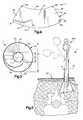
- FIG. 1is an exploded schematic view illustrating an expandable cannula constructed for use with the present invention
- FIG. 2is a perspective view of the cannula of FIG. 1 with parts removed for clarity, the cannula being shown in a contracted condition;
- FIG. 3is a schematic end view showing the cannula of FIG. 1 in the expanded position
- FIG. 4is a rollout view of a part of the cannula of FIG. 1;
- FIG. 5is a schematic sectional view of the cannula of FIG. 1 during a surgical procedure.
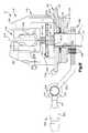
- FIG. 6is an exploded perspective view of an apparatus constructed in accordance with the present invention.
- FIG. 7is a schematic top view of the apparatus of FIG. 6;
- FIG. 8is a schematic sectional view taken along line 8 — 8 in FIG. 7;
- FIG. 9is a schematic sectional view taken along line 9 — 9 in FIG. 7;
- FIG. 10is a schematic view partially in section of part of the apparatus of FIG. 6;
- FIG. 11is a schematic perspective view of a portion of FIG. 10;
- FIG. 12is a schematic sectional view taken along line 12 — 12 in FIG. 9;
- FIG. 13is a schematic sectional view taken along line 13 — 13 in FIG. 9;
- FIG. 14is a schematic detail view of part of the apparatus in FIG. 13;
- FIG. 15is an exploded schematic view of part of the apparatus of FIG. 6;
- FIG. 16is a schematic view taken along line 16 — 16 in FIG. 15;
- FIG. 17is a schematic view showing the parts of FIG. 15 with an associated mechanical arm.
- FIG. 18is a schematic sectional view similar to FIG. 9 showing another feature of the apparatus of FIG. 6 .
- FIG. 6illustrates an apparatus 10 (FIG. 6) for use in percutaneous surgery in association with a cannula 11 (FIG. 2 ).
- the apparatus 10includes a base 118 , a part 140 adapted to be fixed to an endoscope 200 , a screw mechanism 160 connected between the base and the part, and a cannula clamp 180 connected with the base.
- the cannula clamp 180may form a second part of the apparatus 10 that is adapted to be fixed to the cannula 11 .
- the part 140 and endoscope 200are rotatable relative to the cannula clamp 180 .
- a conventional cannulais a cylindrical metal or plastic tube with a channel extending completely through the cannula.
- the channelhas a central axis.
- the cannulais inserted through an incision into a body of a patient during surgery.
- FIGS. 1-5illustrate one suitable cannula 11 constructed for use with an apparatus 10 in accordance with the present invention.
- U.S. patent application Ser. No. 09/772,605, filed Jan. 30, 2001 in the names of Thomas Davison et al.discloses other cannula structures that may be used with the apparatus 10 .
- a specific cannula structureis not envisioned as part of the present invention.
- the cannula 11will be described below by way of example of a cannula usable with the present invention.
- the cannula 11(FIGS. 1-5) is a tubular structure 12 centered on a central axis 14 .
- the tubular structure 12defines a passage 16 through the cannula 11 .
- Surgical instruments and an endoscopeare inserted into a patient's body through the passage 16 during surgery.
- the tubular structure 12comprises a first tubular portion 20 and a second tubular portion 40 attached to the first tubular portion.
- the first tubular portion 20is preferably made of a length of stainless steel tubing, but could alternatively be made of another suitable material.
- the first tubular portion 20has a proximal end 22 and a distal end 24 .
- Parallel cylindrical inner and outer surfaces 26 and 28respectively, extend between the ends 22 , 24 of the first tubular portion 20 .
- the inner surface 26defines a first passage portion 30 of the passage 16 through the cannula 11 .
- the first passage portion 30has a diameter D 1 that is preferably in the range from 10 mm to 30 mm.
- the second tubular portion 40 of the tubular structure 12is attached to the distal end 24 of the first tubular portion 20 .
- the second tubular portion 40is preferably made from stainless steel, but could alternatively be made from another suitable material.
- the second tubular portion 40comprises an arcuate segment 42 of sheet stock.
- the arcuate segment 42includes first and second arcuate edges 44 and 46 , respectively, and first and second planar edges 48 and 50 , respectively.
- the first and second planar edges 48 and 50are rolled in an overlapping manner to form the tubular configuration of the second tubular portion 40 .
- first and second arcuate edges 44 and 46define oppositely disposed first and second ends 60 and 62 (FIGS. 1 and 2 ), respectively, of the second tubular portion.
- the first and second ends 60 and 62are connected by a central portion 64 .
- the first end 60 of the second tubular portion 40is attached to the distal end 24 of the first tubular portion 20 by a single fastener, such as a rivet 66 .
- the rivet 66extends through two aligned apertures 68 (FIG. 4) at the first end 60 of the second tubular portion 40 .
- the first end 60 of the second tubular portion 40is pivotable about the rivet 66 .
- the second tubular portion 40includes parallel inner and outer surfaces 70 and 72 (FIGS. 1 and 2 ), respectively, extending between the first and second ends 60 and 62 .
- the inner surface 70defines a second passage portion 74 of the passage 16 through the cannula 11 that extends as a continuation of the first passage portion 30 in the first tubular portion 20 .
- An arcuate slot 80is formed in the second tubular portion 40 and extends between the inner and outer surfaces 70 and 72 of the second tubular portion.
- the arcuate slot 80extends along a curvilinear path in the central portion 64 of the second tubular portion 40 toward the second end 60 of the second tubular portion.
- the arcuate slot 80has a first terminal end 82 located in the central portion 64 of the second tubular portion 40 .
- a second terminal end 84 of the arcuate slot 80is located adjacent the intersection of the second arcuate edge 46 and the first planar edge 48 of the arcuate segment 42 .
- a guide pin 90is attached to the inner surface 70 of the second tubular portion 40 adjacent the intersection of the second arcuate edge 46 and the second planar edge 50 .
- the guide pin 90In the tubular configuration of the second tubular portion 40 , the guide pin 90 is located in the arcuate slot 80 and is movable along the curvilinear path of the arcuate slot.
- a washer 92is secured to an inner end of the guide pin 90 to retain the guide pin in the arcuate slot 80 .
- the second tubular portion 40 of the tubular structure 12is expandable from a contracted condition shown in FIG. 2 to an expanded condition shown in FIG. 1 .
- the guide pin 90is located in the first terminal end 82 of the arcuate slot 80 in the second tubular portion 40 and the second passage portion 74 defined by the second tubular portion is cylindrical in shape.
- the second passage 74has a generally constant diameter D 2 (FIGS. 2 and 3) that is approximately equal to the diameter D 1 of the first tubular portion 20 .
- the cross-sectional area of the second passage portion 74 at the second end 62 of the second tubular portion 40which is a function of the diameter D 2 , is approximately the same as the cross-sectional area at the first end 60 of the second tubular portion and is approximately the same as the cross-sectional area of the first passage portion 30 in the first tubular portion 20 .
- the guide pin 90is located in the second terminal end 84 of the arcuate slot 80 in the second tubular portion 40 and the second tubular portion has a frustoconical configuration.
- the second passage portion 74has a diameter D 3 (FIG. 3) that is larger then the diameter D 2 of the second passage portion at the first end 60 .
- the diameter D 3 of the second passage portion 74 at the second end 62 of the second tubular portionis 40% to 80% greater than the diameter D 1 of the second passage portion at the first end 60 .
- the cross-sectional area of the second passage portion 74 at the second end 62 of the second tubular portion 40which is a function of the diameter D 3 , is 16% to 64% greater than the cross-sectional area of the second passage portion at the first end 60 of the second tubular portion.
- the cross-sectional area of the second passage portion 74 at the second end 62 of the second tubular portion 40may be large enough to overlie a major portion of at least two adjacent vertebrae of a patient.
- the cannula 11includes an outer layer 31 (FIG. 1) for maintaining the second tubular portion 40 of the cannula 11 in the contracted condition. It is contemplated that other suitable means for maintaining the second tubular portion 40 in the contracted condition could be employed.
- the outer layer 31comprises a section of plastic tubing 32 which is heat shrunk over both the first and second tubular portions 20 , 40 to hold the second tubular portion in the contracted condition.
- a loop of polyester string 34 for tearing the heat shrunk tubing 32is wrapped around the heat shrunk tubing so that it extends both underneath and on top of the tubing.
- An outer end 36 of the string 34extends beyond the tubing 32 .
- FIG. 1shows an actuatable device 35 for expanding the second tubular portion 40 from the contracted condition to the expanded condition.
- the actuatable device 35comprises a manually operated expansion tool 37 .
- the expansion tool 37resembles a common pair of scissors and has a pair of legs 33 pivotally connected to one another.
- the expansion tool 37includes a frustoconical end section 38 formed by a pair of frustoconical halves 39 . Each of the frustoconical halves 39 extends from a respective one of the legs 33 of the expansion tool 37 .
- suitable means for expanding the second tubular portion 40 toward the expanded conditioncould be employed, such as an inflatable balloon (not shown).
- the cannula 11is inserted into the body of a patient in the contracted condition.
- the outer end 36 of the string 34is then manually pulled on by the surgeon. Pulling on the string 34 tears the heat shrunk tubing 32 most of the way along the heat shrunk tubing, which frees the second tubular portion 40 for expansion.
- the heat shrunk tubing 32in its torn condition, may remain attached to the first tubular portion 20 .
- the expansion tool 37is inserted into the passage 16 in the cannula 11 until the frustoconical end section 33 is located at the second end 62 of the second tubular portion 40 .
- the legs 33 of the expansion tool 37are manually separated, causing the frustoconical halves 39 to separate also.
- a radially outward directed forceis exerted on the inner surface 70 of the second tubular portion 40 by the halves 39 , causing the second tubular portion to expand toward the expanded condition.
- the guide pin 90slides from the first terminal end 82 of the arcuate slot 80 to the second terminal end 84 of the arcuate slot to permit the expansion of the second tubular portion 40 .
- the expansion tool 37can be rotated about the central axis 14 to ensure that the second tubular portion 40 of the cannula 11 is completely expanded to the expanded condition.
- the expansion tool 37is then collapsed and removed so that one or more surgical instruments (indicated schematically at 21 in FIG. 5) and a viewing element (indicated schematically as part of the endoscope 200 in FIG. 5) can be received through the cannula 11 and inserted into a patient's body 130 .
- the expanded second tubular portion 40 of the cannula 11provides a large working area for the surgeon inside the body 130 .
- the expanded tubular portion 40can dilate and locally retract and separate spinalis muscle and soft tissues from the vertebrae thereby creating an endoscopic operating field at the surgical site.
- This endoscopic operating field within the spinal musclesdiffers from arthroscopic, laparoscopic, or cystoscopic working spaces in that there is no physiologic space or defined tissue plane that is insufflated with air or distended with fluid.
- the apparatus 10 of the present inventionmay be associated with the cannula 11 of FIGS. 1-5.
- the apparatus 10includes the base 118 .
- the base 118includes a base portion 120 and a guide portion 128 .
- the base portion 120is secured to the guide portion 128 by conventional threaded fasteners 159 (FIG. 13 ).
- the base portion 120comprises a first generally cylindrical platform, or first disk 124 , and a second generally cylindrical understructure, or second disk 125 .
- the first disk 124has an upper circular surface area 124 a .
- the first disk 124has a first circular perimeter 121
- the second disk 125has a second smaller circular perimeter 122 .
- a central, circular aperture 126 in the central area of the first and second disks 124 , 125extends through the disks.
- the first and second perimeters 121 , 122have a center 123 located at the center of the central aperture 126 .
- a cylindrical sleeve part 800is secured to the cannula clamp 180 by conventional fasteners 290 (FIG. 9) and is located in the central aperture 126 .
- the proximal end 22 of the cannula 11can be easily inserted into, and removed from, the sleeve part 800 .
- an axis of the sleeve partextends through the center of the central aperture 126 and the axis of the cannula also extends through the center of the central aperture 126 .
- the cannula 11 and the sleeve part 800are concentric about the central axis 14 .
- the guide portion 128 of the base 118includes a horizontal base part 280 , a first upright member 281 extending upward from the base part, and a second upright member 282 extending upward from the base part.
- the upright members 281 , 282have respective lower portions 283 , 284 extending upward and parallel to each other.
- the upright members 281 , 282further have respective upper portions 285 , 286 extending upward from the lower portions 283 , 284 and toward each other.
- Each upper portion 285 , 286has a respective vertical, linear track 287 , 288 for slidingly receiving the part 140 .
- the base part 280has a right-hand threaded bore 289 extending vertically from a lower surface 291 of the base part to an upper surface 292 of the base part.
- the upper surface 292is located between the upright members 281 , 282 .
- One of the upright members 281 , 282may have a horizontal threaded bore 294 for receiving a stop member 295 .
- the stop member 295has a partially threaded shaft with a non-threaded end that extends horizontally through the upright member 281 or 282 into the area between the upright members 281 , 282 .
- the non-threaded endacts as a vertical limit stop for a part 630 of the screw mechanism 160 .
- the part 140connects to the endoscope 200 .
- the endoscope 200consists of an endoscopic camera 201 and a light port 202 .
- Part of the endoscope 200(FIG. 5) may extend through the channel 12 of the cannula 11 into the patient's body.
- the part 140comprises a generally rectangular body having a passage through which the endoscope 200 extends. As viewed in FIGS. 10 and 11, the part 140 includes six planar sides. These sides define first and second opposite, generally rectangular guide surfaces 451 , 452 (FIG. 8 ), first and second opposite, generally rectangular engagement surfaces 461 , 462 (FIG. 10 ), and first and second opposite, generally square lateral surfaces 471 , 472 .
- the passage in the part 140through which the endoscope 200 extends, includes a first generally rectangular passage portion 441 and a second passage portion 442 sized for receiving the endoscopic camera 201 .
- a transition point 443 in the passageis located where the first passage portion 441 and the second passage portion 442 come together.
- the first passage portion 441extends horizontally from the first lateral surface 471 through about 2 ⁇ 3 of the distance between the lateral surfaces 471 , 472 to the transition point 443 .
- the second passage portion 442includes a cylindrical passage portion that communicates with the first passage portion 441 and extends horizontally from the transition point 443 to the second lateral surface 472 .
- the second passage portion 442forms a circular opening 445 in the lateral surface 472 .
- the perimeter of the circular opening 445forms a surface for tightly engaging the endoscopic camera 201 of the endoscope 200 .
- the part 140further includes a slot 455 for receiving the light port 202 of the endoscope 200 and, an electric cord (not shown) of the endoscope 200 .
- the slot 455extends vertically upward from the first and second passage portions 441 , 442 that receive the endoscopic camera 201 .
- the slot 455intersects the first engagement surface 461 .
- the slot 455extends horizontally from the first lateral surface 471 to the second lateral surface 472 and intersects the lateral surfaces.
- the portion of the slot 455 that is adjacent the first passage portion 441is defined by curved edges 457 for abuttingly engaging the light port 202 .
- the slot 455further includes a cylindrical portion 446 (FIG. 8 ).
- the cylindrical portion 446has a surface that is sized to tightly engage the light port 202 .
- the cylindrical portion 446intersects the second lateral surface 472 and forms a circular opening in the second lateral surface.
- the cylindrical portion 446has a smaller diameter than the first circular opening 445 .
- the curved edges 457 of the slot 455extend a part of the circle defined by the cylindrical portion 446 from the transition point 443 to the first lateral surface 471 .
- the second engagement surface 462 of the part 140includes a generally rectangular slot 465 for receiving a part 623 (FIG. 10) of the screw mechanism 160 .
- the slot 465extends vertically upward from the second engagement surface 462 to the first passage portion 441 .
- the slot 465may have rounded ends, as viewed in FIG. 11 .
- One of the guide surfaces 451 , 452may have one or two threaded bores 458 extending horizontally from the guide surfaces 451 , 452 to the first passage portion 441 .
- These bores 458may have set screws 459 , such as conventional threaded fasteners, or ball plungers 400 (discussed below), threaded into them for engaging and releasably securing the endoscope 200 to the part 140 .
- Each lateral surface 471 , 472has a threaded bore 478 penetrating from the guide surface 471 , 472 to the slot 465 .
- These bores 478may have set screws or ball plungers 400 threaded into them for releasably securing the part 623 of the screw mechanism 160 in the slot 465 .
- a ball plunger 400is illustrated in FIG. 10 releasably securing the part 623 in the slot 465 .
- a ball plunger 400is shown securing the base 118 to the sleeve part 800 .
- a ball plunger 400could optionally be replaced by a set screw 459 .
- Each ball plunger 400including those in the part 140 and base 118 , has an externally threaded tubular body 402 with a cylindrical cavity 404 located therein.
- the cavity 404houses a projection 406 and a coiled spring 408 .
- the spring 408urges each projection 406 against a lip portion 409 of the body 402 .
- the lip portion 409is located at one end of the cavity 404 .
- Each ball plunger 400has projections 406 with spherical detent members 420 and shoulder portions 422 .
- Each ball plunger 400further includes a head portion 430 with a slot 432 for receiving a tool, such as a screwdriver.
- a toolsuch as a screwdriver.
- Each ball plunger 400may be threadedly adjusted within a threaded bore to alter the distance that the spherical detent member 420 projects away from the threaded bore. This distance, along with the stiffness of each spring 408 , will determine a holding force applied by the ball plunger 400 .
- the screw mechanism 160provides for vertical adjustment of the part 140 relative to the base 118 parallel to the central axis 14 of the cannula 11 .
- the screw mechanism 160includes a first large diameter spindle 610 , a second small diameter spindle 620 , and a wheel member, or thumb wheel 630 .
- the thumb wheel 630 and the first spindle 610rotate about a secondary axis 614 parallel to the central axis 14 and spaced apart from the central axis.
- the first spindle 610 and the thumb wheel 630may be made of plastic and integrally molded together as one piece.
- the right-hand threaded bore 289 of the base part 280 , the first spindle 610 , the second spindle 620 , and the thumb wheel 630are all symmetric about the secondary axis 614 .
- the first spindle 610has right-hand male threads 611 for engaging the female threads of the right-hand threaded bore 289 of the base part 280 .
- the second spindle 620has opposite left hand male threads 621 for engaging female threads of a left-hand threaded bore 612 centered on the secondary axis 614 and located in the first spindle 610 .
- the second spindle 620further has the part 623 which is rectangular, planar end portion 623 inserted into the slot 465 of the part 140 .
- the part 623is a generally rectangular, planar end portion of the second spindle 620 .
- Set screws or preferably ball plungers 400threaded into the bores 478 in the part 140 , engage planar surfaces of the end portion 623 and secure (along with the tracks 287 , 288 of the base 118 ) the part 140 against rotational movement relative to the second spindle 620 .
- the ball plungers 400 or set screwsalso releasably secure the part 140 against axial movement relative to the end portion 623 of the second spindle 620 .
- the end portion 623 of the second spindle 620may have hemispherical recesses 625 for receiving the end of the set screws or the spherical detent members 420 of the ball plungers 400 (FIG. 10 ).
- the second spindle 620may be removed from the slot 465 of the part 140 by disengaging the ends of the set screws from the hemispherical recesses 625 or by overcoming the bias of the spherical detent members 420 in the hemispherical recesses.
- the thumb wheel 630has a knurled perimeter 631 to facilitate manual rotation of the thumb wheel about the secondary axis 614 .
- the threaded engagement between the right-hand female threads of the right-hand threaded bore 289 of the base 118 and the right-hand male threads 611 of the first spindle 610either raises or lowers the first spindle vertically relative to the base depending upon the direction of rotation.
- the threaded engagement between the left-hand female threads of the left-hand threaded bore 612 of the first spindle 610 and the left-hand male threads 621 of the second spindle 620either raises or lowers (depending on the direction of rotation) the second spindle vertically relative to the first spindle.
- This opposite hand thread arrangementresults in an amplified movement of the second spindle 620 for each single rotation of the thumb wheel 630 because the two sets of threads work in concert to axially move the first spindle 610 and second spindle in the same direction, instead of acting against each other as would occur if the threads were both left-hand or both right-hand.
- the part 140being secured to the end portion 623 of the second spindle 620 , is moved linearly parallel to the axis 14 of the cannula 11 (or vertically) upon rotation of the thumb wheel 630 .
- the part 140slides along the linear tracks 287 , 288 of the guide portion 128 with the stop member 295 providing an upper limit for the position of the part 140 .
- the tracks 287 , 288may engage the lateral surfaces 271 , 272 of the part 140 and block rotation of the part.
- the tracks 287 , 288guide the vertical movement of the part 140 .
- the endoscope 200is vertically adjusted since it is secured in the passage in the part 140 , as described above.
- the cannula clamp 180includes two gripper arms 182 , 184 that are deflected toward each other to clamp against the outer surface 28 of the cannula 11 , a gripper actuating lever 976 for deflecting the gripper arms 182 , 184 into gripping engagement with the outer surface 28 of the cannula, and an adjustment mechanism 186 for changing the relative position of the gripper arms 182 , 184 from which the arms are moved by the actuating lever to enable the arms to clamp different diameter cannulas.
- the gripper actuating lever 976also releases the gripper arms 182 , 184 from gripping engagement with the outer surface 28 of the cannula 11 .
- the two gripper arms 182 , 184may grip the plastic tubing 32 depending on the position of the plastic tubing on the first tubular portion 20 of the cannula 11 (as described above). References in this application to gripping the outer surface of the cannula are meant to also cover the gripper arms engaging the plastic tubing.
- the adjustment mechanism 186includes a threaded stud 977 with a longitudinal axis, an adjustment knob 989 with a female threaded bore, and a lock pin 990 .
- the threaded stud 977has a head 979 , a threaded shaft 980 for screwing into, and through, the threaded bore of the adjustment knob 989 , and an oblong, or flat end 981 which extends through an oblong bore 183 in the gripper arm 182 .
- Alternative structures for the adjustment mechanism 186are envisioned by the present invention.
- the flat end 981 of the threaded stud 977is threaded through the bore of the adjustment knob 989 and inserted horizontally through a circular bore (not shown) in the gripper arm 184 that is larger in diameter than the diameter of the threaded stud 977 and through the oblong bore 183 in the gripper arm 182 .
- the flat end 981 of the threaded stud 977is then horizontally inserted into a longitudinal slot 975 in the lever 976 .
- the threaded stud 977is secured against rotation relative to gripper arms 182 , 184 by engaging surfaces of the gripper arms 182 , 184 defining bore 183 on gripper arm 182 and similar surfaces on arm 184 defining the oblong bore in arm 184 .
- the lock pin 990is then inserted vertically through a bore (not shown) in the lever 976 and through a bore (not shown) in the flat end 981 of the threaded stud 977 thereby securing the adjustment mechanism 186 together.
- the lever 976is free to rotate about the lock pin 990 .
- the adjustment knob 989may be axially positioned along the threaded stud 977 by rotation of the adjustment knob about the secured threaded stud.
- the gripper arm 184moves relative to the threaded stud 977 and the distance between the gripper arms 182 , 184 changes and the relative positions of the gripper arms change.
- Rotation of the adjustment knob 989 in one directionmay move the gripper arms 182 , 184 closer together and rotation in the opposite direction may allow the arms to spring apart.
- a camming surface 978 on the lever 976adjacent the gripper arm 182 , moves the arms 182 , 184 a predetermined distance together to grip the outer surface 28 of the cannula 11 as the lever 976 is rotated clockwise about the lock pin 990 to the position shown in FIG. 12 .
- Counterclockwise rotation of the lever 976 about the lock pin 990from the position shown in FIG. 12, allows the gripper arms 182 , 184 to spring (move) apart and releases the outer surface 28 of the cannula 11 from the cannula clamp 180 .
- the gripper arms 182 , 184have a normal position from which the gripper arms may be moved a predetermined distance by the actuating lever 976 to grip a cannula 11 having a first diameter. Rotation of the adjustment knob 989 in one direction relative to the stud 977 causes arms 182 , 184 to resiliently deflect toward each other and take new positions. The gripper arms 182 , 184 may be moved from these new positions a predetermined distance by the actuating lever 976 to grip a cannula 11 having a second diameter smaller than the first diameter. Rotation of the adjustment knob 989 in a second direction opposite the first direction allows the gripper arms 182 , 184 to spring back toward their normal positions. It should be apparent that the adjustment knob 989 enables the cannula clamp 180 to securely grip cannulas of different diameters.
- the base 118 and parts (i.e., the endoscope) attached to the basemay move along the central axis 14 of the cannula 11 relative to the cannula.
- the endoscope 200may be positioned on the apparatus 10 and axially adjusted along the central axis 14 in this manner.
- the screw mechanism 160provides for vertical adjustment of the endoscope 200 relative to the cannula.
- the cylindrical sleeve part 800which is secured to the cannula clamp 180 , may be inserted into the central aperture 126 of the base 118 .
- the sleeve part 800has a passage extending through the sleeve part, which passage receives the cannula 11 .
- the upper edges of the sleeve part 800 and the proximal end 22 of the cannula 11are typically assembled flush with the upper surface area 124 a of the first disk 124 .
- the sleeve part 800is centered about the central axis 14 and includes a cylindrical outer surface 810 , a horizontal groove 814 which extends around the cylindrical outer surface, and a horizontal array of spaced apart recesses 816 in the cylindrical outer surface.
- the recesses 816lie in a horizontal plane parallel to, and axially offset from, a plane defined by the groove 814 , both planes being perpendicular to the central axis 14 .
- the sleeve part 800is axially secured in the central aperture 126 of the base 118 by set screws 459 or, more preferably, by ball plungers 400 extending radially into the central aperture and engaging the groove 814 .
- the sleeve part 800is rotationally (and axially) secured in the central aperture 126 of the base 118 by the set screws 459 or the ball plungers 400 extending radially into the central aperture and being received in the recesses 816 .
- the set screws 459 or ball plungers 400are threaded radially inward through threaded radial bores 127 that penetrate radially inward from the second perimeter 122 of the base 118 to the central aperture 126 .
- radial bores 127 aare axially aligned with the groove 814 and are located at 90° increments about the central aperture 126 .
- four additional radial bores 127 bare axially aligned with the recesses 816 at 90° increments, but angularly offset 45° from the four bores 127 a.
- set screws 459are used, the distal ends of the set screws form detents that engage the groove 814 and support the sleeve part 800 in the central aperture 126 , but allow the base 118 and sleeve part to rotate relatively about the central axis 14 .
- the recesses 816 of the sleeve part 800 and the detents formed by set screws 459form an indexing mechanism that secures the sleeve part at selected angular increments about the central axis 14 relative to the base 118 . Thirty-six (36) recesses 816 are, spaced about the cylindrical outer surface 810 at 10 ′ increments.
- the base 118may be rotated about the central axis 14 relative to the fixed cannula clamp 180 , while the base 118 is axially secured by the set screws 459 engaging the groove 814 .
- the set screws 459may be threaded inward for reengaging the recesses 816 and rotationally securing the base 118 to the cannula clamp 180 .
- An access bore 129is located in the base part 280 for providing access to the bore 127 b that is disposed against the guide portion 128 of the base 118 .
- the spherical detent members 420form detents that engage in the groove 814 and support the sleeve part 800 in the central aperture 126 , but allow the base 118 and the sleeve part to rotate about the central axis 14 .
- the recesses 816 of the sleeve part 800 and the detents formed by ball plungers 400form an indexing mechanism that secures the sleeve part at selected angular increments about the central axis 14 relative to the base 118 . Thirty-six (36) recesses 816 are spaced about the cylindrical outer surface 810 at 10° increments.
- the base 118may be rotated about the central axis 14 relative to the fixed cannula clamp 180 , thereby disengaging the biased spherical detent members 420 from the recesses 816 .
- the base 118will remain axially secured by the ball plungers 400 engaging the groove 814 .
- the spherical detent members 420reengage the recesses after 10° of rotation.
- the manual force applied to the basecan continue to rotate the base.
- the base 118 and the endoscope 200may rotate about 270° about the central axis 14 of the cannula 11 and be adjustably fixed at 10° increments. This enables the surgeon to view different parts of the surgical site, as desired.
- the sleeve part 800 of the cannula clamp 180can be easily removed from the central aperture 126 for cleaning, maintenance, etc. of the parts by disengaging the set screws 459 from the groove 814 and the recesses 816 , or by overcoming the biasing force applied by the ball plungers 400 to the sleeve part.
- the sleeve part 800may have an annular retaining lip 813 for engaging the proximal end 22 of the cannula 11 .
- the retaining lip 813extends radially inward and provides an upper limit stop that prevents the cannula 11 from extending upward (axially) from the central aperture 126 .
- the upper edge of the retaining lip 813is typically mounted flush with the upper surface area 124 a of the first disk 124 .
- the cannula clamp 180is a part of the support arm 300 for attaching the apparatus 10 to a mechanical robotic arm 301 .
- the support arm 300includes an arm portion 302 which may be formed integrally with the gripper arms 182 , 184 . As viewed in FIG. 9, the arm portion 302 extends upwardly away from the gripper arms 182 , 184 in order to minimize the possibility of contact with the patient during surgery.
- the support arm 300also includes an arm portion 303 .
- the arm portion 303has an attaching structure 304 , including a groove 305 , which snaps into a socket in the mechanical arm 301 .
- Detents of any suitable type and designated 306 in the mechanical arm 301hold the arm portion 303 in position in the socket in the mechanical arm 301 .
- the detents 306may be controlled by external actuation levers (not shown) on the mechanical arm 301 for manually releasing the arm portion 303 from the mechanical arm 301 .
- the arm portions 302 and 303are pivotally connected to each other by a fastener 310 .
- the fastener 310extends through an opening 311 in the arm portion 302 and threads into a threaded opening 312 in the arm portion 303 .
- the arm portions 302 , 303may pivot relative each other about a pivot axis 314 .
- the pivot axis 314is centered on the axis of the fastener 310 and the axis of the threaded opening 312 .
- the arm portions 302 , 303are secured together against pivoting movement.
- the arm portions 303 , 302may pivot relative to each other about the axis 314 .
- the end of the arm portion 302which is adjacent to the arm portion 303 , has a convex surface 350 , which is curved about the axis 314 .
- the arm portion 303has a concave surface 351 , which is also curved about the axis 314 .
- the surfaces 350 , 351move concentrically relative to each other when the arm portions 302 , 303 pivot relatively about the axis 314 .
- the arm portion 303has a set of teeth 320 which encircle the axis 314 and which project axially toward a set of teeth 321 on the arm portion 302 .
- the teeth 321project axially toward the teeth 320 .
- the teeth 320 and the teeth 321mesh with each other and provide a locking action so that the arm portions 302 , 303 are positively locked against relative movement about the axis 314 when the fastener 310 is tightly screwed into the opening 312 .
- the teeth 320 , 321define a lock which blocks relative rotation of the arm portions 302 , 303 about the axis 314 .
- the arm portions 302 , 303When the fastener 310 is loosened, the arm portions 302 , 303 may be rotated relative to each other about the axis 314 , and thus, the arm portions 302 , 303 may pivot relative to each other to adjust the position of the apparatus 10 .
- a cylindrical projection 325is welded to the arm portion 303 .
- the projection 325 and arm portion 303are fixedly connected together.
- the projection 325is centered on the axis 314 and contains a chamber 328 .
- the chamber 328communicates with a fluid passage 329 in a male fluid connector 331 .
- the male connector 331attaches to a male connector 333 on the mechanical arm 301 by means of a flexible hose 392 so that the fluid passage 329 communicates with a fluid passage in the mechanical arm 301 .
- the chamber 328is closed at its upper end by a cap 335 .
- the cap 335has an opening 336 centered on the axis 314 .
- the opening 336communicates with the chamber 328 .
- a manually movable internal valve member 340normally closes the opening and blocks the chamber 328 from communicating with the ambient air surrounding the support arm 300 .
- the valve member 340is connected to a stem 341 , which is also centered on the axis 314 .
- the stem 341has a knob or button 343 on its end which may be manually depressed to move the stem 341 and valve member 340 downward into the chamber 328 .
- the stem 341 and valve member 340are so moved, the chamber 328 is in communication with the ambient air surrounding the device due to the unblocking of the opening 336 .
- the mechanical arm 301is a known device and is of the type generally disclosed in U.S. Pat. No. 4,863,133.
- the mechanical arm 301is sold by Leonard Medical, Inc. 1464 Holcomb Road, Huntington Valley, Pa., 19006.
- the mechanical arm 301includes relatively movable parts, which permit movement and adjustment of the apparatus 10 in a variety in planes, directions, and orientations.
- the mechanical arm 301permits easy movement when a vacuum is not applied to the arm 301 . When a vacuum is applied to the arm 301 , relative movement of the parts of the arm 301 is resisted, and therefore adjustment of the apparatus 10 is difficult.
- the chamber 328loses its vacuum and the pressure in the chamber 328 increases toward ambient pressure.
- the passage 329communicates this pressure increase to the mechanical arm 301 , and thus the parts of the mechanical arm 301 are free to move and allow for adjustment of the position of the apparatus 10 by the surgeon.
- the support arm 300is snapped into the socket of the mechanical arm 301 where it is held by the detent 306 .
- the surgeonmay then depress the button 343 and relatively move parts of the mechanical arm 301 as well as the apparatus 10 into the position where the surgeon desires the apparatus 10 to be.
- This positionmay be where the central aperture 126 of the base 118 and the sleeve portion 800 are aligned with the proximal end 22 of the cannula 11 and the distal end 24 of the cannula 11 is located in an incision in the body of a patient.
- the endoscope 200may be mounted on the apparatus 10 , and the surgeon may make adjustments prior to, and during, the surgical procedure as desired, as described above.
- the fixed connection of the sleeve portion 800 to the support arm 300may be made by one or more suitable metal fasteners 290 , such as rivets or bolts.
- the sleeve portion 800is axially offset from the gripper arms 182 , 184 in order to allow the gripper arms to flex against the outer surface 28 of the cannula 11 .
- the entire apparatus 10can be constructed from metal or any other suitable material having sufficient mechanical strength, flexibility, and durability. Certain parts may be made from materials permitting X-rays and other techniques for viewing the surgical site (i.e., radiopaque parts). Other parts may also be made from non-magnetic materials to reduce electromagnetic interference (i.e., electromagnetic insulating parts).
Landscapes
- Health & Medical Sciences (AREA)
- Life Sciences & Earth Sciences (AREA)
- Surgery (AREA)
- Nuclear Medicine, Radiotherapy & Molecular Imaging (AREA)
- Biomedical Technology (AREA)
- Optics & Photonics (AREA)
- Pathology (AREA)
- Radiology & Medical Imaging (AREA)
- Biophysics (AREA)
- Engineering & Computer Science (AREA)
- Physics & Mathematics (AREA)
- Heart & Thoracic Surgery (AREA)
- Medical Informatics (AREA)
- Molecular Biology (AREA)
- Animal Behavior & Ethology (AREA)
- General Health & Medical Sciences (AREA)
- Public Health (AREA)
- Veterinary Medicine (AREA)
- Endoscopes (AREA)
Abstract
Description
The present invention relates to an apparatus for supporting an endoscope and, more particularly, for supporting an endoscope for viewing a surgical site in a patient during surgery on the patient.
Percutaneous surgery is a procedure in which surgical instruments, and typically an endoscope, are inserted through a cannula into the body of a patient. A viewing element, typically a small video camera, is part of the endoscope and is connected to a television monitor so that the surgeon may view the surgical site.
The cannula is a hollow tube. The cannula is inserted through an incision into the body of a patient. The instruments and the endoscope are inserted through the cannula. The cannula also allows the instruments and endoscope to be removed from the body and/or adjusted in the body during the surgery.
A conventional apparatus for supporting the endoscope allows a surgeon to manipulate the surgical instruments without also moving the endoscope. Also, a known support apparatus allows adjustment of the endoscope relative to the cannula for viewing different areas at the surgical site.
In accordance with one feature of the present invention, an apparatus supports an endoscope for viewing a surgical site in a patient during surgery on the patient. The apparatus includes a base, a part adapted to be fixed to the endoscope, and a screw mechanism. The base has a guide portion. The part engages the guide portion and is movable relative to the guide portion. The screw mechanism connects the base and the part. At least a portion of the screw mechanism is rotatable to slide the part relative to the guide portion to change a position of the endoscope relative to the patient.
In accordance with another feature of the present invention, an apparatus supports an endoscope for viewing a surgical site in a patient during surgery on the patient. The endoscope extends through a cannula into the patient. The apparatus includes a base, a support mechanism for supporting the endoscope on the base, a cannula clamp, and a connection between the base and the cannula clamp. The cannula clamp clamps against an outer surface of the cannula. The connection enables the base to rotate relative to the cannula clamp about an axis of the cannula. The connection includes an index mechanism with parts interposed between the base and the cannula clamp for retaining the base at incremental relatively rotated positions relative to the cannula clamp.
In accordance with still another feature of the present invention, an apparatus supports an endoscope for viewing a surgical site in a patient during surgery on the patient. The endoscope extends through a cannula into the patient. The apparatus includes a base and a cannula clamp. The base supports the endoscope. The cannula clamp includes a pair of arms for clamping against an outer surface of the cannula through which the endoscope extends. The apparatus includes an actuator for moving the arms a predetermined distance toward each other to effect clamping against the cannula. The cannula clamp further includes an adjustment mechanism for changing the relative position of the arms from which the arms are moved by the actuator to enable the arms to clamp different diameter cannulas.
In accordance with yet another feature of the present invention, an apparatus supports an endoscope for viewing a surgical site in a patient during surgery on the patient. The apparatus includes a part for engaging the endoscope. The part has a first surface portion for engaging an external surface of the endoscope and a second surface portion spaced apart from the first surface portion for engaging an outer surface of the endoscope defining a light port.
In accordance with still another feature of the present invention, an apparatus supports an endoscope for viewing a surgical site in a patient during surgery on the patient. The apparatus includes a base, a first part, a second part, and a mechanism for enabling axial and rotational adjustment of the first part relative to the second part. The base is for supporting the endoscope. The first part is adapted to be fixed to the endoscope. The second part is adapted to be fixed to a cannula with a longitudinal axis. The mechanism includes a member supported on the base for rotation relative to the base about an axis parallel to the longitudinal axis of the cannula and spaced apart from the longitudinal axis of the cannula.
In accordance with yet another feature of the present invention, an apparatus supports an endoscope for viewing a surgical site in a patient during surgery on the patient. The apparatus includes a cannula for insertion into the patient, a cannula clamp, a base, and a part supported for linear movement on the base relative to the base. The cannula clamp engages an outer surface of the cannula. The base is supported for rotation relative to the cannula clamp about a longitudinal axis of the cannula. The part is adapted to be fixed to the endoscope. The part moves in a path parallel to the longitudinal axis of the cannula.
The foregoing and other features of the present invention will become more apparent to one skilled in the art upon consideration of the following description of the invention and the accompanying drawings, in which:
FIG. 1 is an exploded schematic view illustrating an expandable cannula constructed for use with the present invention;
FIG. 2 is a perspective view of the cannula of FIG. 1 with parts removed for clarity, the cannula being shown in a contracted condition;
FIG. 3 is a schematic end view showing the cannula of FIG. 1 in the expanded position;
FIG. 4 is a rollout view of a part of the cannula of FIG. 1;
FIG. 5 is a schematic sectional view of the cannula of FIG. 1 during a surgical procedure.
FIG. 6 is an exploded perspective view of an apparatus constructed in accordance with the present invention;
FIG. 7 is a schematic top view of the apparatus of FIG. 6;
FIG. 8 is a schematic sectional view taken alongline 8—8 in FIG. 7;
FIG. 9 is a schematic sectional view taken alongline 9—9 in FIG. 7;
FIG. 10 is a schematic view partially in section of part of the apparatus of FIG. 6;
FIG. 11 is a schematic perspective view of a portion of FIG. 10;
FIG. 12 is a schematic sectional view taken alongline 12—12 in FIG. 9;
FIG. 13 is a schematic sectional view taken alongline 13—13 in FIG. 9;
FIG. 14 is a schematic detail view of part of the apparatus in FIG. 13;
FIG. 15 is an exploded schematic view of part of the apparatus of FIG. 6;
FIG. 16 is a schematic view taken alongline 16—16 in FIG. 15;
FIG. 17 is a schematic view showing the parts of FIG. 15 with an associated mechanical arm; and
FIG. 18 is a schematic sectional view similar to FIG. 9 showing another feature of the apparatus of FIG.6.
As representative of the present invention, the Figures illustrate an apparatus10 (FIG. 6) for use in percutaneous surgery in association with a cannula11 (FIG.2). Theapparatus 10 includes abase 118, apart 140 adapted to be fixed to anendoscope 200, ascrew mechanism 160 connected between the base and the part, and acannula clamp 180 connected with the base. Thecannula clamp 180 may form a second part of theapparatus 10 that is adapted to be fixed to thecannula 11. Thepart 140 andendoscope 200 are rotatable relative to thecannula clamp 180.
A conventional cannula is a cylindrical metal or plastic tube with a channel extending completely through the cannula. The channel has a central axis. The cannula is inserted through an incision into a body of a patient during surgery.
FIGS. 1-5 illustrate onesuitable cannula 11 constructed for use with anapparatus 10 in accordance with the present invention. U.S. patent application Ser. No. 09/772,605, filed Jan. 30, 2001 in the names of Thomas Davison et al., discloses other cannula structures that may be used with theapparatus 10. A specific cannula structure is not envisioned as part of the present invention. Thecannula 11 will be described below by way of example of a cannula usable with the present invention.
The cannula11 (FIGS. 1-5) is atubular structure 12 centered on acentral axis 14. Thetubular structure 12 defines apassage 16 through thecannula 11. Surgical instruments and an endoscope are inserted into a patient's body through thepassage 16 during surgery.
Thetubular structure 12 comprises a firsttubular portion 20 and a secondtubular portion 40 attached to the first tubular portion. The firsttubular portion 20 is preferably made of a length of stainless steel tubing, but could alternatively be made of another suitable material. The firsttubular portion 20 has aproximal end 22 and adistal end 24. Parallel cylindrical inner andouter surfaces ends tubular portion 20. Theinner surface 26 defines afirst passage portion 30 of thepassage 16 through thecannula 11. Thefirst passage portion 30 has a diameter D1 that is preferably in the range from 10 mm to 30 mm.
The secondtubular portion 40 of thetubular structure 12 is attached to thedistal end 24 of the firsttubular portion 20. The secondtubular portion 40 is preferably made from stainless steel, but could alternatively be made from another suitable material.
As best seen in the rollout view of FIG. 4, the secondtubular portion 40 comprises anarcuate segment 42 of sheet stock. Thearcuate segment 42 includes first and secondarcuate edges planar edges planar edges tubular portion 40.
When the secondtubular portion 40 has been rolled into its tubular configuration, the first and secondarcuate edges central portion 64. Thefirst end 60 of the secondtubular portion 40 is attached to thedistal end 24 of the firsttubular portion 20 by a single fastener, such as arivet 66. Therivet 66 extends through two aligned apertures68 (FIG. 4) at thefirst end 60 of the secondtubular portion 40. Thefirst end 60 of the secondtubular portion 40 is pivotable about therivet 66.
The secondtubular portion 40 includes parallel inner andouter surfaces 70 and72 (FIGS.1 and2), respectively, extending between the first and second ends60 and62. Theinner surface 70 defines asecond passage portion 74 of thepassage 16 through thecannula 11 that extends as a continuation of thefirst passage portion 30 in the firsttubular portion 20.
Anarcuate slot 80 is formed in the secondtubular portion 40 and extends between the inner andouter surfaces arcuate slot 80 extends along a curvilinear path in thecentral portion 64 of the secondtubular portion 40 toward thesecond end 60 of the second tubular portion. Thearcuate slot 80 has a firstterminal end 82 located in thecentral portion 64 of the secondtubular portion 40. A secondterminal end 84 of thearcuate slot 80 is located adjacent the intersection of the secondarcuate edge 46 and the firstplanar edge 48 of thearcuate segment 42.
Aguide pin 90 is attached to theinner surface 70 of the secondtubular portion 40 adjacent the intersection of the secondarcuate edge 46 and the secondplanar edge 50. In the tubular configuration of the secondtubular portion 40, theguide pin 90 is located in thearcuate slot 80 and is movable along the curvilinear path of the arcuate slot. Awasher 92 is secured to an inner end of theguide pin 90 to retain the guide pin in thearcuate slot 80.
The secondtubular portion 40 of thetubular structure 12 is expandable from a contracted condition shown in FIG. 2 to an expanded condition shown in FIG.1. In the contracted condition, theguide pin 90 is located in the firstterminal end 82 of thearcuate slot 80 in the secondtubular portion 40 and thesecond passage portion 74 defined by the second tubular portion is cylindrical in shape. Thesecond passage 74 has a generally constant diameter D2 (FIGS. 2 and 3) that is approximately equal to the diameter D1 of the firsttubular portion 20. Thus, the cross-sectional area of thesecond passage portion 74 at thesecond end 62 of the secondtubular portion 40, which is a function of the diameter D2, is approximately the same as the cross-sectional area at thefirst end 60 of the second tubular portion and is approximately the same as the cross-sectional area of thefirst passage portion 30 in the firsttubular portion 20.
In the expanded condition, theguide pin 90 is located in the secondterminal end 84 of thearcuate slot 80 in the secondtubular portion 40 and the second tubular portion has a frustoconical configuration. At thesecond end 62 of the secondtubular portion 40, thesecond passage portion 74 has a diameter D3 (FIG. 3) that is larger then the diameter D2 of the second passage portion at thefirst end 60. Preferably, the diameter D3 of thesecond passage portion 74 at thesecond end 62 of the second tubular portion is 40% to 80% greater than the diameter D1 of the second passage portion at thefirst end 60.
Thus, in the expanded condition, the cross-sectional area of thesecond passage portion 74 at thesecond end 62 of the secondtubular portion 40, which is a function of the diameter D3, is 16% to 64% greater than the cross-sectional area of the second passage portion at thefirst end 60 of the second tubular portion. In the expanded condition, the cross-sectional area of thesecond passage portion 74 at thesecond end 62 of the secondtubular portion 40 may be large enough to overlie a major portion of at least two adjacent vertebrae of a patient.
Thecannula 11 includes an outer layer31 (FIG. 1) for maintaining the secondtubular portion 40 of thecannula 11 in the contracted condition. It is contemplated that other suitable means for maintaining the secondtubular portion 40 in the contracted condition could be employed. Theouter layer 31 comprises a section ofplastic tubing 32 which is heat shrunk over both the first and secondtubular portions
In addition, a loop ofpolyester string 34 for tearing the heat shrunktubing 32 is wrapped around the heat shrunk tubing so that it extends both underneath and on top of the tubing. Anouter end 36 of thestring 34 extends beyond thetubing 32.
FIG. 1 shows anactuatable device 35 for expanding the secondtubular portion 40 from the contracted condition to the expanded condition. Theactuatable device 35 comprises a manually operatedexpansion tool 37. Theexpansion tool 37 resembles a common pair of scissors and has a pair oflegs 33 pivotally connected to one another. Theexpansion tool 37 includes afrustoconical end section 38 formed by a pair offrustoconical halves 39. Each of thefrustoconical halves 39 extends from a respective one of thelegs 33 of theexpansion tool 37. It is contemplated that other suitable means for expanding the secondtubular portion 40 toward the expanded condition could be employed, such as an inflatable balloon (not shown).
During an endoscopic surgical procedure, thecannula 11 is inserted into the body of a patient in the contracted condition. Theouter end 36 of thestring 34 is then manually pulled on by the surgeon. Pulling on thestring 34 tears the heat shrunktubing 32 most of the way along the heat shrunk tubing, which frees the secondtubular portion 40 for expansion. The heat shrunktubing 32, in its torn condition, may remain attached to the firsttubular portion 20.
Next, theexpansion tool 37 is inserted into thepassage 16 in thecannula 11 until thefrustoconical end section 33 is located at thesecond end 62 of the secondtubular portion 40. Thelegs 33 of theexpansion tool 37 are manually separated, causing thefrustoconical halves 39 to separate also. As thehalves 39 separate, a radially outward directed force is exerted on theinner surface 70 of the secondtubular portion 40 by thehalves 39, causing the second tubular portion to expand toward the expanded condition. Under the force of the expandingexpansion tool 37, theguide pin 90 slides from the firstterminal end 82 of thearcuate slot 80 to the secondterminal end 84 of the arcuate slot to permit the expansion of the secondtubular portion 40. Theexpansion tool 37 can be rotated about thecentral axis 14 to ensure that the secondtubular portion 40 of thecannula 11 is completely expanded to the expanded condition. Theexpansion tool 37 is then collapsed and removed so that one or more surgical instruments (indicated schematically at21 in FIG. 5) and a viewing element (indicated schematically as part of theendoscope 200 in FIG. 5) can be received through thecannula 11 and inserted into a patient'sbody 130. The expanded secondtubular portion 40 of thecannula 11 provides a large working area for the surgeon inside thebody 130.
The expandedtubular portion 40 can dilate and locally retract and separate spinalis muscle and soft tissues from the vertebrae thereby creating an endoscopic operating field at the surgical site. This endoscopic operating field within the spinal muscles differs from arthroscopic, laparoscopic, or cystoscopic working spaces in that there is no physiologic space or defined tissue plane that is insufflated with air or distended with fluid.
As viewed in FIG. 6, theapparatus 10 of the present invention may be associated with thecannula 11 of FIGS. 1-5. Theapparatus 10 includes thebase 118. Thebase 118 includes abase portion 120 and aguide portion 128. Thebase portion 120 is secured to theguide portion 128 by conventional threaded fasteners159 (FIG.13).
Thebase portion 120 comprises a first generally cylindrical platform, orfirst disk 124, and a second generally cylindrical understructure, orsecond disk 125. Thefirst disk 124 has an uppercircular surface area 124a. Thefirst disk 124 has a firstcircular perimeter 121, and thesecond disk 125 has a second smallercircular perimeter 122. A central,circular aperture 126 in the central area of the first andsecond disks second perimeters center 123 located at the center of thecentral aperture 126.
Acylindrical sleeve part 800 is secured to thecannula clamp 180 by conventional fasteners290 (FIG. 9) and is located in thecentral aperture 126. Theproximal end 22 of thecannula 11 can be easily inserted into, and removed from, thesleeve part 800. When thecannula 11 is located in thesleeve part 800, an axis of the sleeve part extends through the center of thecentral aperture 126 and the axis of the cannula also extends through the center of thecentral aperture 126. Thus, thecannula 11 and thesleeve part 800 are concentric about thecentral axis 14.
As viewed in FIG. 8, theguide portion 128 of thebase 118 includes ahorizontal base part 280, afirst upright member 281 extending upward from the base part, and asecond upright member 282 extending upward from the base part. Theupright members lower portions upright members upper portions 285,286 extending upward from thelower portions upper portion 285,286 has a respective vertical,linear track part 140.
Thebase part 280 has a right-hand threaded bore289 extending vertically from alower surface 291 of the base part to anupper surface 292 of the base part. Theupper surface 292 is located between theupright members
One of theupright members stop member 295. Thestop member 295 has a partially threaded shaft with a non-threaded end that extends horizontally through theupright member upright members part 630 of thescrew mechanism 160.
As viewed in FIG. 6, thepart 140 connects to theendoscope 200. Theendoscope 200 consists of anendoscopic camera 201 and alight port 202. Part of the endoscope200 (FIG. 5) may extend through thechannel 12 of thecannula 11 into the patient's body.
Thepart 140 comprises a generally rectangular body having a passage through which theendoscope 200 extends. As viewed in FIGS. 10 and 11, thepart 140 includes six planar sides. These sides define first and second opposite, generally rectangular guide surfaces451,452 (FIG.8), first and second opposite, generally rectangular engagement surfaces461,462 (FIG.10), and first and second opposite, generally squarelateral surfaces
The passage in thepart 140, through which theendoscope 200 extends, includes a first generallyrectangular passage portion 441 and asecond passage portion 442 sized for receiving theendoscopic camera 201. Atransition point 443 in the passage is located where thefirst passage portion 441 and thesecond passage portion 442 come together.
Thefirst passage portion 441 extends horizontally from the firstlateral surface 471 through about ⅔ of the distance between thelateral surfaces transition point 443. Thesecond passage portion 442 includes a cylindrical passage portion that communicates with thefirst passage portion 441 and extends horizontally from thetransition point 443 to the secondlateral surface 472. Thesecond passage portion 442 forms acircular opening 445 in thelateral surface 472. The perimeter of thecircular opening 445 forms a surface for tightly engaging theendoscopic camera 201 of theendoscope 200.
Thepart 140 further includes aslot 455 for receiving thelight port 202 of theendoscope 200 and, an electric cord (not shown) of theendoscope 200. Theslot 455 extends vertically upward from the first andsecond passage portions endoscopic camera 201. Theslot 455 intersects thefirst engagement surface 461. Theslot 455 extends horizontally from the firstlateral surface 471 to the secondlateral surface 472 and intersects the lateral surfaces. The portion of theslot 455 that is adjacent thefirst passage portion 441 is defined bycurved edges 457 for abuttingly engaging thelight port 202.
Theslot 455 further includes a cylindrical portion446 (FIG.8). Thecylindrical portion 446 has a surface that is sized to tightly engage thelight port 202. Thecylindrical portion 446 intersects the secondlateral surface 472 and forms a circular opening in the second lateral surface. Thecylindrical portion 446 has a smaller diameter than the firstcircular opening 445. Thecurved edges 457 of theslot 455 extend a part of the circle defined by thecylindrical portion 446 from thetransition point 443 to the firstlateral surface 471.
Thesecond engagement surface 462 of thepart 140 includes a generallyrectangular slot 465 for receiving a part623 (FIG. 10) of thescrew mechanism 160. Theslot 465 extends vertically upward from thesecond engagement surface 462 to thefirst passage portion 441. Theslot 465 may have rounded ends, as viewed in FIG.11.
One of the guide surfaces451,452 may have one or two threadedbores 458 extending horizontally from the guide surfaces451,452 to thefirst passage portion 441. Thesebores 458 may have setscrews 459, such as conventional threaded fasteners, or ball plungers400 (discussed below), threaded into them for engaging and releasably securing theendoscope 200 to thepart 140.
Eachlateral surface bore 478 penetrating from theguide surface slot 465. Thesebores 478 may have set screws orball plungers 400 threaded into them for releasably securing thepart 623 of thescrew mechanism 160 in theslot 465. Aball plunger 400 is illustrated in FIG. 10 releasably securing thepart 623 in theslot 465.
As viewed in FIG. 14, aball plunger 400 is shown securing the base118 to thesleeve part 800. Such aball plunger 400 could optionally be replaced by aset screw 459. Eachball plunger 400, including those in thepart 140 andbase 118, has an externally threadedtubular body 402 with acylindrical cavity 404 located therein. Thecavity 404 houses aprojection 406 and acoiled spring 408. Thespring 408 urges eachprojection 406 against alip portion 409 of thebody 402. Thelip portion 409 is located at one end of thecavity 404. Eachball plunger 400 hasprojections 406 withspherical detent members 420 andshoulder portions 422.
Eachball plunger 400 further includes ahead portion 430 with aslot 432 for receiving a tool, such as a screwdriver. Eachball plunger 400 may be threadedly adjusted within a threaded bore to alter the distance that thespherical detent member 420 projects away from the threaded bore. This distance, along with the stiffness of eachspring 408, will determine a holding force applied by theball plunger 400.
As viewed in FIG. 8, thescrew mechanism 160 provides for vertical adjustment of thepart 140 relative to the base118 parallel to thecentral axis 14 of thecannula 11. Thescrew mechanism 160 includes a firstlarge diameter spindle 610, a secondsmall diameter spindle 620, and a wheel member, orthumb wheel 630. Thethumb wheel 630 and thefirst spindle 610 rotate about asecondary axis 614 parallel to thecentral axis 14 and spaced apart from the central axis. Thefirst spindle 610 and thethumb wheel 630 may be made of plastic and integrally molded together as one piece. The right-hand threaded bore289 of thebase part 280, thefirst spindle 610, thesecond spindle 620, and thethumb wheel 630 are all symmetric about thesecondary axis 614.
Thefirst spindle 610 has right-hand male threads 611 for engaging the female threads of the right-hand threaded bore289 of thebase part 280. As thefirst spindle 610 is rotated, due to manual force applied to thethumb wheel 630, about thesecondary axis 614, thefirst spindle 610 moves axially along thesecondary axis 614 vertically into, or out of, the right-hand threaded bore depending upon the direction of rotation. Thesecond spindle 620 has opposite left handmale threads 621 for engaging female threads of a left-hand threaded bore612 centered on thesecondary axis 614 and located in thefirst spindle 610.
Thesecond spindle 620 further has thepart 623 which is rectangular,planar end portion 623 inserted into theslot 465 of thepart 140. Thepart 623 is a generally rectangular, planar end portion of thesecond spindle 620. Set screws or preferablyball plungers 400, threaded into thebores 478 in thepart 140, engage planar surfaces of theend portion 623 and secure (along with thetracks part 140 against rotational movement relative to thesecond spindle 620. The ball plungers400 or set screws also releasably secure thepart 140 against axial movement relative to theend portion 623 of thesecond spindle 620.
Theend portion 623 of thesecond spindle 620 may havehemispherical recesses 625 for receiving the end of the set screws or thespherical detent members 420 of the ball plungers400 (FIG.10). Thesecond spindle 620 may be removed from theslot 465 of thepart 140 by disengaging the ends of the set screws from thehemispherical recesses 625 or by overcoming the bias of thespherical detent members 420 in the hemispherical recesses.
Thethumb wheel 630 has aknurled perimeter 631 to facilitate manual rotation of the thumb wheel about thesecondary axis 614. When rotation is imparted to thethumb wheel 630, the threaded engagement between the right-hand female threads of the right-hand threaded bore289 of thebase 118 and the right-hand male threads 611 of thefirst spindle 610 either raises or lowers the first spindle vertically relative to the base depending upon the direction of rotation. Simultaneously, the threaded engagement between the left-hand female threads of the left-hand threaded bore612 of thefirst spindle 610 and the left-hand male threads 621 of thesecond spindle 620 either raises or lowers (depending on the direction of rotation) the second spindle vertically relative to the first spindle. This opposite hand thread arrangement results in an amplified movement of thesecond spindle 620 for each single rotation of thethumb wheel 630 because the two sets of threads work in concert to axially move thefirst spindle 610 and second spindle in the same direction, instead of acting against each other as would occur if the threads were both left-hand or both right-hand.
Thepart 140, being secured to theend portion 623 of thesecond spindle 620, is moved linearly parallel to theaxis 14 of the cannula11 (or vertically) upon rotation of thethumb wheel 630. Thepart 140 slides along thelinear tracks guide portion 128 with thestop member 295 providing an upper limit for the position of thepart 140. As thepart 140 moves, thetracks part 140 and block rotation of the part. Also, thetracks part 140. Upon vertical movement of thepart 140, theendoscope 200 is vertically adjusted since it is secured in the passage in thepart 140, as described above.
As viewed in FIG. 12, thecannula clamp 180 includes twogripper arms outer surface 28 of thecannula 11, agripper actuating lever 976 for deflecting thegripper arms outer surface 28 of the cannula, and anadjustment mechanism 186 for changing the relative position of thegripper arms gripper actuating lever 976 also releases thegripper arms outer surface 28 of thecannula 11. When released, the gripper arms will spring away from theouter surface 28 of thecannula 11. The twogripper arms plastic tubing 32 depending on the position of the plastic tubing on the firsttubular portion 20 of the cannula11 (as described above). References in this application to gripping the outer surface of the cannula are meant to also cover the gripper arms engaging the plastic tubing.
Theadjustment mechanism 186 includes a threadedstud 977 with a longitudinal axis, anadjustment knob 989 with a female threaded bore, and alock pin 990. The threadedstud 977 has ahead 979, a threadedshaft 980 for screwing into, and through, the threaded bore of theadjustment knob 989, and an oblong, orflat end 981 which extends through anoblong bore 183 in thegripper arm 182. Alternative structures for theadjustment mechanism 186 are envisioned by the present invention.
During assembly, theflat end 981 of the threadedstud 977 is threaded through the bore of theadjustment knob 989 and inserted horizontally through a circular bore (not shown) in thegripper arm 184 that is larger in diameter than the diameter of the threadedstud 977 and through theoblong bore 183 in thegripper arm 182. Theflat end 981 of the threadedstud 977 is then horizontally inserted into alongitudinal slot 975 in thelever 976. The threadedstud 977 is secured against rotation relative to gripperarms gripper arms bore 183 ongripper arm 182 and similar surfaces onarm 184 defining the oblong bore inarm 184. Thelock pin 990 is then inserted vertically through a bore (not shown) in thelever 976 and through a bore (not shown) in theflat end 981 of the threadedstud 977 thereby securing theadjustment mechanism 186 together. Thelever 976 is free to rotate about thelock pin 990.
Theadjustment knob 989 may be axially positioned along the threadedstud 977 by rotation of the adjustment knob about the secured threaded stud. By changing the axial position of theadjustment knob 989, thegripper arm 184 moves relative to the threadedstud 977 and the distance between thegripper arms adjustment knob 989 in one direction may move thegripper arms
A camming surface978 on thelever 976, adjacent thegripper arm 182, moves thearms 182,184 a predetermined distance together to grip theouter surface 28 of thecannula 11 as thelever 976 is rotated clockwise about thelock pin 990 to the position shown in FIG.12. Counterclockwise rotation of thelever 976 about thelock pin 990, from the position shown in FIG. 12, allows thegripper arms outer surface 28 of thecannula 11 from thecannula clamp 180.
Thegripper arms actuating lever 976 to grip acannula 11 having a first diameter. Rotation of theadjustment knob 989 in one direction relative to thestud 977causes arms gripper arms actuating lever 976 to grip acannula 11 having a second diameter smaller than the first diameter. Rotation of theadjustment knob 989 in a second direction opposite the first direction allows thegripper arms adjustment knob 989 enables thecannula clamp 180 to securely grip cannulas of different diameters.
When thecannula clamp 180 is released from thecannula 11, thebase 118 and parts (i.e., the endoscope) attached to the base may move along thecentral axis 14 of thecannula 11 relative to the cannula. After theapparatus 10 is initially aligned with thecannula 11, theendoscope 200 may be positioned on theapparatus 10 and axially adjusted along thecentral axis 14 in this manner. After thecannula clamp 180 grips theouter surface 28 of thecannula 11, thescrew mechanism 160 provides for vertical adjustment of theendoscope 200 relative to the cannula.
As viewed in FIG. 6, thecylindrical sleeve part 800, which is secured to thecannula clamp 180, may be inserted into thecentral aperture 126 of thebase 118. Thesleeve part 800 has a passage extending through the sleeve part, which passage receives thecannula 11. As viewed in FIG. 9, the upper edges of thesleeve part 800 and theproximal end 22 of thecannula 11 are typically assembled flush with theupper surface area 124aof thefirst disk 124. Thesleeve part 800 is centered about thecentral axis 14 and includes a cylindricalouter surface 810, ahorizontal groove 814 which extends around the cylindrical outer surface, and a horizontal array of spaced apart recesses816 in the cylindrical outer surface. Therecesses 816 lie in a horizontal plane parallel to, and axially offset from, a plane defined by thegroove 814, both planes being perpendicular to thecentral axis 14.
As viewed in FIG. 13, thesleeve part 800 is axially secured in thecentral aperture 126 of the base118 byset screws 459 or, more preferably, byball plungers 400 extending radially into the central aperture and engaging thegroove 814. Thesleeve part 800 is rotationally (and axially) secured in thecentral aperture 126 of the base118 by theset screws 459 or theball plungers 400 extending radially into the central aperture and being received in therecesses 816. Theset screws 459 orball plungers 400 are threaded radially inward through threaded radial bores127 that penetrate radially inward from thesecond perimeter 122 of the base118 to thecentral aperture 126. Fourradial bores 127aare axially aligned with thegroove 814 and are located at 90° increments about thecentral aperture 126. Correspondingly, four additional radial bores127bare axially aligned with therecesses 816 at 90° increments, but angularly offset 45° from the fourbores 127a.
If setscrews 459 are used, the distal ends of the set screws form detents that engage thegroove 814 and support thesleeve part 800 in thecentral aperture 126, but allow thebase 118 and sleeve part to rotate relatively about thecentral axis 14. Therecesses 816 of thesleeve part 800 and the detents formed byset screws 459 form an indexing mechanism that secures the sleeve part at selected angular increments about thecentral axis 14 relative to thebase 118. Thirty-six (36) recesses816 are, spaced about the cylindricalouter surface 810 at10′ increments. Thus, when theset screws 459 are threadedly disengaged from therecesses 816, thebase 118 may be rotated about thecentral axis 14 relative to the fixedcannula clamp 180, while thebase 118 is axially secured by theset screws 459 engaging thegroove 814. After 10° of rotation (or some multiple of 10°), theset screws 459 may be threaded inward for reengaging therecesses 816 and rotationally securing the base118 to thecannula clamp 180. An access bore129 is located in thebase part 280 for providing access to thebore 127bthat is disposed against theguide portion 128 of thebase 118.
If ball plungers400 are used, which is preferable, thespherical detent members 420 form detents that engage in thegroove 814 and support thesleeve part 800 in thecentral aperture 126, but allow thebase 118 and the sleeve part to rotate about thecentral axis 14. Therecesses 816 of thesleeve part 800 and the detents formed byball plungers 400 form an indexing mechanism that secures the sleeve part at selected angular increments about thecentral axis 14 relative to thebase 118. Thirty-six (36) recesses816 are spaced about the cylindricalouter surface 810 at 10° increments. Thus, with minimal manual force to overcome the biasing force of theball plungers 400, thebase 118 may be rotated about thecentral axis 14 relative to the fixedcannula clamp 180, thereby disengaging the biasedspherical detent members 420 from therecesses 816. The base118 will remain axially secured by theball plungers 400 engaging thegroove 814. Thespherical detent members 420 reengage the recesses after 10° of rotation.
However, if rotation of the base118 more than 10° is desired, the manual force applied to the base can continue to rotate the base. As should be apparent, thebase 118 and theendoscope 200 may rotate about 270° about thecentral axis 14 of thecannula 11 and be adjustably fixed at 10° increments. This enables the surgeon to view different parts of the surgical site, as desired.
Thesleeve part 800 of thecannula clamp 180 can be easily removed from thecentral aperture 126 for cleaning, maintenance, etc. of the parts by disengaging theset screws 459 from thegroove 814 and therecesses 816, or by overcoming the biasing force applied by theball plungers 400 to the sleeve part. As viewed in FIG. 18, thesleeve part 800 may have anannular retaining lip 813 for engaging theproximal end 22 of thecannula 11. The retaininglip 813 extends radially inward and provides an upper limit stop that prevents thecannula 11 from extending upward (axially) from thecentral aperture 126. The upper edge of the retaininglip 813 is typically mounted flush with theupper surface area 124aof thefirst disk 124.
As viewed in FIGS. 15-17, thecannula clamp 180 is a part of thesupport arm 300 for attaching theapparatus 10 to a mechanicalrobotic arm 301. Thesupport arm 300 includes anarm portion 302 which may be formed integrally with thegripper arms arm portion 302 extends upwardly away from thegripper arms
Thesupport arm 300 also includes anarm portion 303. Thearm portion 303 has an attachingstructure 304, including agroove 305, which snaps into a socket in themechanical arm 301. Detents of any suitable type and designated306 in themechanical arm 301, hold thearm portion 303 in position in the socket in themechanical arm 301. Thedetents 306 may be controlled by external actuation levers (not shown) on themechanical arm 301 for manually releasing thearm portion 303 from themechanical arm 301.
Thearm portions fastener 310. Thefastener 310 extends through anopening 311 in thearm portion 302 and threads into a threadedopening 312 in thearm portion 303. When thefastener 310 is released, thearm portions pivot axis 314. Thepivot axis 314 is centered on the axis of thefastener 310 and the axis of the threadedopening 312. When thefastener 310 is tightly screwed into the threadedopening 312, thearm portions fastener 310 is released, thearm portions axis 314.
The end of thearm portion 302, which is adjacent to thearm portion 303, has aconvex surface 350, which is curved about theaxis 314. Thearm portion 303 has aconcave surface 351, which is also curved about theaxis 314. Thesurfaces arm portions axis 314.
Thearm portion 303 has a set ofteeth 320 which encircle theaxis 314 and which project axially toward a set ofteeth 321 on thearm portion 302. Theteeth 321 project axially toward theteeth 320. Theteeth 320 and theteeth 321 mesh with each other and provide a locking action so that thearm portions axis 314 when thefastener 310 is tightly screwed into theopening 312. Theteeth arm portions axis 314. When thefastener 310 is loosened, thearm portions axis 314, and thus, thearm portions apparatus 10.
Acylindrical projection 325 is welded to thearm portion 303. Thus, theprojection 325 andarm portion 303 are fixedly connected together. Theprojection 325 is centered on theaxis 314 and contains achamber 328.
As viewed in FIG. 17, thechamber 328 communicates with afluid passage 329 in amale fluid connector 331. Themale connector 331 attaches to amale connector 333 on themechanical arm 301 by means of aflexible hose 392 so that thefluid passage 329 communicates with a fluid passage in themechanical arm 301.
As viewed in FIG. 15, thechamber 328 is closed at its upper end by acap 335. Thecap 335 has anopening 336 centered on theaxis 314. Theopening 336 communicates with thechamber 328. A manually movableinternal valve member 340 normally closes the opening and blocks thechamber 328 from communicating with the ambient air surrounding thesupport arm 300. Thevalve member 340 is connected to astem 341, which is also centered on theaxis 314. Thestem 341 has a knob orbutton 343 on its end which may be manually depressed to move thestem 341 andvalve member 340 downward into thechamber 328. When thestem 341 andvalve member 340 are so moved, thechamber 328 is in communication with the ambient air surrounding the device due to the unblocking of theopening 336.
Themechanical arm 301 is a known device and is of the type generally disclosed in U.S. Pat. No. 4,863,133. Themechanical arm 301 is sold by Leonard Medical, Inc. 1464 Holcomb Road, Huntington Valley, Pa., 19006. Themechanical arm 301 includes relatively movable parts, which permit movement and adjustment of theapparatus 10 in a variety in planes, directions, and orientations. Themechanical arm 301 permits easy movement when a vacuum is not applied to thearm 301. When a vacuum is applied to thearm 301, relative movement of the parts of thearm 301 is resisted, and therefore adjustment of theapparatus 10 is difficult.
When thebutton 343 is depressed, thechamber 328 loses its vacuum and the pressure in thechamber 328 increases toward ambient pressure. Thepassage 329 communicates this pressure increase to themechanical arm 301, and thus the parts of themechanical arm 301 are free to move and allow for adjustment of the position of theapparatus 10 by the surgeon.
Accordingly, when the surgeon uses theapparatus 10, thesupport arm 300 is snapped into the socket of themechanical arm 301 where it is held by thedetent 306. The surgeon may then depress thebutton 343 and relatively move parts of themechanical arm 301 as well as theapparatus 10 into the position where the surgeon desires theapparatus 10 to be. This position may be where thecentral aperture 126 of thebase 118 and thesleeve portion 800 are aligned with theproximal end 22 of thecannula 11 and thedistal end 24 of thecannula 11 is located in an incision in the body of a patient. Theendoscope 200 may be mounted on theapparatus 10, and the surgeon may make adjustments prior to, and during, the surgical procedure as desired, as described above.
As viewed in FIG. 9, the fixed connection of thesleeve portion 800 to thesupport arm 300 may be made by one or moresuitable metal fasteners 290, such as rivets or bolts. Thesleeve portion 800 is axially offset from thegripper arms outer surface 28 of thecannula 11.
Theentire apparatus 10 can be constructed from metal or any other suitable material having sufficient mechanical strength, flexibility, and durability. Certain parts may be made from materials permitting X-rays and other techniques for viewing the surgical site (i.e., radiopaque parts). Other parts may also be made from non-magnetic materials to reduce electromagnetic interference (i.e., electromagnetic insulating parts).
From the above description of the invention, those skilled in the art will perceive improvements, changes and modifications. Such improvements, changes and modifications within the skill of the art are intended to be covered by the appended claims.
Claims (42)
1. An apparatus for supporting an endoscope for viewing a surgical site in a patient during surgery on the patient, said apparatus comprising:
a base having a guide portion;
a part adapted to be fixed to the endoscope, said part engaging said guide portion and being movable relative to said guide portion; and
a screw mechanism connected between said base and said part, at least a portion of said screw mechanism being rotatable to slide said part relative to said guide portion to change a position of the endoscope relative to the patient.
2. The apparatus as defined inclaim 1 further including a thumb wheel for rotating said portion of said screw mechanism to change the position of said part relative to said guide portion.
3. The apparatus as defined inclaim 2 wherein said screw mechanism comprises a first threaded spindle rotatably screwed into first threads on said base, and a second threaded spindle fixed against rotation relative to said guide portion, said second threaded spindle being rotatably screwed into second threads on said first spindle, said thumb wheel rotating said first threaded spindle.
4. The apparatus as defined inclaim 3 wherein said first threads and said second threads are of opposite hand.
5. The apparatus as defined inclaim 1 wherein said part engages a track on said guide portion, said track allowing linear movement of said part relative to said base.
6. The apparatus as defined inclaim 1 wherein said base further includes a base portion with a central aperture for receiving an end portion of a cannula.
7. The apparatus as defined inclaim 1 further including a cannula clamp associated with said base and a connection between said base and said cannula clamp, said connection enabling said base to rotate relative to said cannula clamp about an axis of a cannula.
8. The apparatus as defined inclaim 7 wherein said connection includes an index mechanism for retaining said base at incremental angular positions about the axis of the cannula.
9. The apparatus as defined inclaim 8 wherein said index mechanism includes a sleeve part, said sleeve part being disposed symmetrically about the axis of the cannula.
10. The apparatus as defined inclaim 9 wherein said sleeve part includes a series of angularly spaced apart recesses and said base includes spaced apart members for receipt in said recesses for fixing the angular position of said base relative to the cannula.
11. An apparatus for supporting an endoscope for viewing a surgical site in a patient during surgery on the patient, the endoscope extending through a cannula into the patient, said apparatus comprising:
a base;
a support mechanism for supporting the endoscope on said base;
a cannula clamp for clamping against an outer surface of the cannula; and
a connection between said base and said cannula clamp, said connection enabling said base to rotate relative to said cannula clamp about an axis of the cannula, said connection including an index mechanism with parts interposed between said base and said cannula clamp for retaining said base at incremental relatively rotated positions relative to said cannula clamp.
12. The apparatus as defined inclaim 11 wherein said parts of said index mechanism include a first part connected with one of said base and cannula clamp, said first part having a series of angularly spaced apart recesses, said parts of said index mechanism further including a second part connected with the other of said base and cannula clamp, said second part being received by said recesses.
13. The apparatus as defined inclaim 12 wherein said base has a central aperture and said cannula clamp has a sleeve part secured thereto, said sleeve part being received in said central aperture, said sleeve part having said recesses, said base including spring biased detents on said base for receipt in said recesses.
14. The apparatus as defined inclaim 13 wherein said sleeve part has a passage therethrough for receiving the cannula.
15. The apparatus as defined inclaim 11 further including a part adapted to be fixed to the endoscope, said base including a guide portion, said part engaging said guide portion and being movable relative to said guide portion.
16. The apparatus as defined inclaim 15 further including a screw mechanism connected between said base and said part, said screw mechanism being rotatable to slide said part relative to said guide portion.
17. The apparatus as defined inclaim 15 wherein said guide portion includes two spaced apart upright members extending parallel to each other.
18. The apparatus as defined inclaim 16 wherein said screw mechanism includes a first spindle with right-hand male threads and a second spindle with left-hand male threads.
19. The apparatus as defined inclaim 11 wherein said cannula clamp includes an adjustment mechanism for allowing said cannula clamp to attach to cannulas of different sizes.
20. The apparatus as defined inclaim 11 further including an actuating lever for actuating said cannula clamp to clamp against a cannula.
21. An apparatus for supporting an endoscope for viewing a surgical site in a patient during surgery on the patient, the endoscope extending through a cannula into the patient, said apparatus comprising:
a base for supporting the endoscope;
a cannula clamp including a pair of spaced apart arms for clamping against an outer surface of the cannula through which the endoscope extends; and
an actuator for moving said arms a predetermined distance toward each other to effect clamping against a cannula;
said cannula clamp further including an adjustment mechanism for changing the relative position of said arms from which said arms are moved by said actuator to enable said arms to clamp different diameter cannulas.
22. The apparatus as defined inclaim 21 wherein said adjustment mechanism comprises a threaded member extending through openings in said arms, said arms being movable relative to said threaded member and a knob threaded on said threaded member and which on rotation moves axially on said threaded member to change the relative positions of said arms.
23. The apparatus as defined inclaim 21 further including a part adapted to be fixed to the endoscope, said base including a guide portion, said guide portion engaging said part and allowing vertical movement of said part relative to said guide portion.
24. The apparatus as defined inclaim 23 further including a screw mechanism connected between said base and said part.
25. The apparatus as defined inclaim 24 wherein said screw mechanism is rotatable to slide said part relative to said guide portion.
26. The apparatus as defined inclaim 24 further including a thumb wheel for rotating a portion of said screw mechanism.
27. The apparatus as defined inclaim 23 wherein said guide portion includes a linear track for preventing rotation of said part relative to said base.
28. The apparatus as defined inclaim 23 further including a screw mechanism for imparting vertical linear movement to the endoscope relative to a cannula.
29. The apparatus as defined inclaim 21 further including an index mechanism for retaining said base at incremental relatively rotated positions relative to said cannula clamp.
30. The apparatus as defined inclaim 21 wherein said cannula clamp is adapted to rotate and move linearly relative to the endoscope.
31. An apparatus for supporting an endoscope for viewing a surgical site in a patient during surgery on the patient, said apparatus comprising:
a part for engaging the endoscope, said part having a first surface portion for engaging opposed sides of the endoscope and a second surface portion spaced apart from said first surface portion for engaging a part of the endoscope defining a light port.
32. The apparatus as defined inclaim 31 further including a base for supporting said part for axial movement of said part relative to an axis of a cannula.
33. The apparatus as defined inclaim 32 wherein said base has a guide portion for guiding axial movement of said part and preventing rotation of said part relative to a cannula.
34. The apparatus as defined inclaim 31 further including a cannula clamp associated with said base for clamping against an outer surface of a cannula.
35. The apparatus as defined inclaim 34 wherein said cannula clamp includes two arms, and further including an adjustment mechanism for enabling said arms to clamp different diameter cannulas.
36. The apparatus as defined inclaim 32 further including a screw mechanism associated with said base for axially moving said part to adjust the position of an endoscope relative to an axis of a cannula.
37. The apparatus as defined inclaim 36 wherein said part includes a slot for receiving said screw mechanism and further including a threaded member connecting said part and said screw mechanism in said slot.
38. The apparatus as defined inclaim 31 further including an index mechanism associated with said base for enabling incremental rotational adjustment of the position of said base and the endoscope relative to a cannula.
39. The apparatus as defined inclaim 31 further including a base associated with said part and a mechanism for adjusting the position of the part and the endoscope relative to said base.
40. The apparatus as defined inclaim 39 wherein said mechanism includes a sleeve for engaging an end of a cannula, said sleeve having an axis, said base and said sleeve being relatively rotatable about said axis of said sleeve.
41. An apparatus for supporting an endoscope for viewing a surgical site in a patient during surgery on the patient, said apparatus comprising:
a base for supporting the endoscope;
a first part adapted to be fixed to the endoscope;
a second part adapted to be fixed to a cannula with a longitudinal axis; and
a mechanism for axially and rotationally adjusting said first part relative to said second part, said mechanism including a member supported on said base for rotation on said base about an axis parallel to the longitudinal axis of the cannula and spaced from the longitudinal axis of the cannula.
42. An apparatus for supporting an endoscope for viewing a surgical site in a patient during surgery on the patient, said apparatus comprising:
a cannula for insertion into a patient, said cannula having a longitudinal axis;
a cannula clamp for adjustably engaging an outer surface of said cannula;
a base supported for rotation relative to said cannula clamp about a longitudinal axis of said cannula; and
a part adapted to be fixed to an endoscope, said part being supported for linear movement on said base, the movement of said part being parallel to said longitudinal axis of said cannula.
Priority Applications (4)
| Application Number | Priority Date | Filing Date | Title |
|---|---|---|---|
| US09/821,297US6530880B2 (en) | 2001-03-29 | 2001-03-29 | Apparatus for supporting an endoscope |
| AU2002250471AAU2002250471A1 (en) | 2001-03-29 | 2002-03-28 | Apparatus for adjustably supporting an endoscope |
| PCT/US2002/009657WO2002078767A2 (en) | 2001-03-29 | 2002-03-28 | Apparatus for adjustably supporting an endoscope |
| EP02719383AEP1372458A4 (en) | 2001-03-29 | 2002-03-28 | Apparatus for adjustably supporting an endoscope |
Applications Claiming Priority (1)
| Application Number | Priority Date | Filing Date | Title |
|---|---|---|---|
| US09/821,297US6530880B2 (en) | 2001-03-29 | 2001-03-29 | Apparatus for supporting an endoscope |
Publications (2)
| Publication Number | Publication Date |
|---|---|
| US20020143235A1 US20020143235A1 (en) | 2002-10-03 |
| US6530880B2true US6530880B2 (en) | 2003-03-11 |
Family
ID=25233032
Family Applications (1)
| Application Number | Title | Priority Date | Filing Date |
|---|---|---|---|
| US09/821,297Expired - LifetimeUS6530880B2 (en) | 2001-03-29 | 2001-03-29 | Apparatus for supporting an endoscope |
Country Status (1)
| Country | Link |
|---|---|
| US (1) | US6530880B2 (en) |
Cited By (76)
| Publication number | Priority date | Publication date | Assignee | Title |
|---|---|---|---|---|
| US20020035874A1 (en)* | 2000-09-28 | 2002-03-28 | Toyo Radiator Co., Ltd. | Pressure cap |
| US20030040656A1 (en)* | 2001-08-27 | 2003-02-27 | Endius Incorporated | Apparatus for adjustably supporting an endoscope |
| US20030073998A1 (en)* | 2000-08-01 | 2003-04-17 | Endius Incorporated | Method of securing vertebrae |
| US20030153927A1 (en)* | 2001-05-15 | 2003-08-14 | Endius Incorporated | Structure for receiving surgical instruments |
| US20030195551A1 (en)* | 1998-08-20 | 2003-10-16 | Davison Thomas W. | Cannula for receiving surgical instruments |
| US20030236529A1 (en)* | 2002-06-24 | 2003-12-25 | Endius Incorporated | Surgical instrument for moving vertebrae |
| US20040116954A1 (en)* | 1998-08-20 | 2004-06-17 | Endius Inc. | Surgical tool for use in expanding a cannula |
| US20040133201A1 (en)* | 2000-08-01 | 2004-07-08 | Alan Shluzas | Methods and apparatuses for treating the spine through an access device |
| US20040148369A1 (en)* | 2002-07-11 | 2004-07-29 | John Strassner | Repository-independent system and method for asset management and reconciliation |
| US20040230100A1 (en)* | 2003-05-16 | 2004-11-18 | Shluzas Alan E. | Access device for minimally invasive surgery |
| US20050075540A1 (en)* | 2003-08-26 | 2005-04-07 | Shluzas Alan E. | Minimally invasive access device and method |
| US20050075644A1 (en)* | 2003-10-02 | 2005-04-07 | Dipoto Gene | Methods and apparatuses for minimally invasive replacement of intervertebral discs |
| US20050090899A1 (en)* | 2003-10-24 | 2005-04-28 | Dipoto Gene | Methods and apparatuses for treating the spine through an access device |
| US20050090833A1 (en)* | 2003-10-24 | 2005-04-28 | Dipoto Gene | Methods and apparatuses for fixation of the spine through an access device |
| US20050090822A1 (en)* | 2003-10-24 | 2005-04-28 | Dipoto Gene | Methods and apparatus for stabilizing the spine through an access device |
| US20050159650A1 (en)* | 2003-12-18 | 2005-07-21 | Depuy Spine, Inc. | Surgical methods and surgical kits |
| US20050171551A1 (en)* | 2003-10-21 | 2005-08-04 | William Sukovich | Instrument and method for preparing a bone to receive an implant |
| US20050251192A1 (en)* | 2004-03-31 | 2005-11-10 | Shluzas Alan E | Access device having discrete visualization locations |
| US20050273131A1 (en)* | 2003-08-26 | 2005-12-08 | Shluzas Alan E | Access systems and methods for minimally invasive surgery |
| US20060052812A1 (en)* | 2004-09-07 | 2006-03-09 | Michael Winer | Tool for preparing a surgical site for an access device |
| US20060089652A1 (en)* | 2004-10-26 | 2006-04-27 | Concept Matrix, Llc | Working channel for minimally invasive spine surgery |
| US20060089662A1 (en)* | 1998-08-20 | 2006-04-27 | Davison Thomas W | Method and apparatus for securing vertebrae |
| WO2006045089A2 (en) | 2004-10-20 | 2006-04-27 | Endius Incorporated | An apparatus for connecting a longitudinal member to a bone portion |
| US20060195017A1 (en)* | 2004-11-22 | 2006-08-31 | Shluzas Alan E | Expandable device for providing access to the spine |
| US20070016223A1 (en)* | 2002-10-25 | 2007-01-18 | Pagliuca James J | Apparatus and methods for shielding body structures during surgery |
| US20070043365A1 (en)* | 2005-07-19 | 2007-02-22 | Stephen Ritland | Rod extension for extending fusion construct |
| US20070156026A1 (en)* | 2006-01-04 | 2007-07-05 | William Frasier | Surgical access devices and methods of minimally invasive surgery |
| US20070233089A1 (en)* | 2006-02-17 | 2007-10-04 | Endius, Inc. | Systems and methods for reducing adjacent level disc disease |
| WO2007146833A2 (en) | 2006-06-09 | 2007-12-21 | Endius, Inc. | Methods and apparatus for access to and/or treatment of the spine |
| US20080077143A1 (en)* | 2006-09-25 | 2008-03-27 | Zimmer Spine, Inc. | Apparatus for connecting a longitudinal member to a bone portion |
| US7539628B2 (en)* | 2000-03-21 | 2009-05-26 | Bennett James D | Online purchasing system supporting buyer affordability screening |
| US7618444B2 (en) | 2002-09-06 | 2009-11-17 | Zimmer Spine, Inc. | Surgical instrument for moving a vertebra |
| US7641670B2 (en) | 1998-08-20 | 2010-01-05 | Zimmer Spine, Inc. | Cannula for receiving surgical instruments |
| US7651496B2 (en) | 2004-07-23 | 2010-01-26 | Zimmer Spine, Inc. | Methods and apparatuses for percutaneous implant delivery |
| US7655025B2 (en) | 2001-09-28 | 2010-02-02 | Stephen Ritland | Adjustable rod and connector device and method of use |
| US7658739B2 (en) | 2005-09-27 | 2010-02-09 | Zimmer Spine, Inc. | Methods and apparatuses for stabilizing the spine through an access device |
| US7682375B2 (en) | 2002-05-08 | 2010-03-23 | Stephen Ritland | Dynamic fixation device and method of use |
| US7695498B2 (en) | 2001-09-28 | 2010-04-13 | Stephen Ritland | Connection rod for screw or hook polyaxial system and method of use |
| US7753939B2 (en) | 2000-06-30 | 2010-07-13 | Stephen Ritland | Polyaxial connection device and method |
| US7758501B2 (en) | 2006-01-04 | 2010-07-20 | Depuy Spine, Inc. | Surgical reactors and methods of minimally invasive surgery |
| US7763047B2 (en) | 2002-02-20 | 2010-07-27 | Stephen Ritland | Pedicle screw connector apparatus and method |
| US7918792B2 (en) | 2006-01-04 | 2011-04-05 | Depuy Spine, Inc. | Surgical retractor for use with minimally invasive spinal stabilization systems and methods of minimally invasive surgery |
| US7955257B2 (en) | 2006-01-05 | 2011-06-07 | Depuy Spine, Inc. | Non-rigid surgical retractor |
| US7959564B2 (en) | 2006-07-08 | 2011-06-14 | Stephen Ritland | Pedicle seeker and retractor, and methods of use |
| US8262571B2 (en) | 2003-05-22 | 2012-09-11 | Stephen Ritland | Intermuscular guide for retractor insertion and method of use |
| USRE44268E1 (en) | 1997-07-15 | 2013-06-04 | Zimmer Spine, Inc. | Method and instruments for percutaneous arthroscopic disc removal, bone biopsy and fixation of the vertebral |
| US8504438B2 (en) | 2000-03-21 | 2013-08-06 | James D. Bennett | Online purchasing system supporting lenders with affordability screening |
| US8583612B2 (en) | 2007-08-29 | 2013-11-12 | Enpulz, L.L.C. | Whois server verifying whois records and search engine accesses |
| US8666965B2 (en) | 2008-05-13 | 2014-03-04 | Enpulz, L.L.C. | Web search with visited web page search result restrictions |
| US8782072B2 (en) | 2008-06-05 | 2014-07-15 | Enpulz, L.L.C. | Search engine supporting mixed image and text search input |
| US20140243597A1 (en)* | 2013-02-27 | 2014-08-28 | Ethicon Endo-Surgery, Inc. | System for performing a minimally invasive surgical procedure |
| US20140276596A1 (en)* | 2010-11-01 | 2014-09-18 | Biomet Manufacturing, Llc | Cannulated syringe |
| US8892588B2 (en) | 2008-06-05 | 2014-11-18 | Enpulz, L.L.P. | Search system employing multiple image based search processing approaches |
| US8932334B2 (en) | 2002-04-05 | 2015-01-13 | Stephen Ritland | Dynamic fixation device and method of use |
| US9009184B2 (en) | 2008-05-15 | 2015-04-14 | Enpulz, Llc | Web search with multi-language search input translation |
| US9058321B2 (en) | 2008-05-16 | 2015-06-16 | Enpluz, LLC | Support for international search terms—translate as you crawl |
| US9177061B2 (en) | 2007-08-29 | 2015-11-03 | Enpulz, Llc | Search engine with geographical verification processing |
| US9223869B2 (en) | 2008-05-16 | 2015-12-29 | Rpx Corporation | Browser based language recognition supporting central web search translation |
| US9277957B2 (en) | 2012-08-15 | 2016-03-08 | Ethicon Endo-Surgery, Inc. | Electrosurgical devices and methods |
| US9375268B2 (en) | 2007-02-15 | 2016-06-28 | Ethicon Endo-Surgery, Inc. | Electroporation ablation apparatus, system, and method |
| US9572623B2 (en) | 2012-08-02 | 2017-02-21 | Ethicon Endo-Surgery, Inc. | Reusable electrode and disposable sheath |
| US9788888B2 (en) | 2012-07-03 | 2017-10-17 | Ethicon Endo-Surgery, Inc. | Endoscopic cap electrode and method for using the same |
| US9788856B2 (en) | 2014-03-11 | 2017-10-17 | Stryker European Holdings I, Llc | Endoscopic surgical systems and methods |
| US9883910B2 (en) | 2011-03-17 | 2018-02-06 | Eticon Endo-Surgery, Inc. | Hand held surgical device for manipulating an internal magnet assembly within a patient |
| US10004558B2 (en) | 2009-01-12 | 2018-06-26 | Ethicon Endo-Surgery, Inc. | Electrical ablation devices |
| US10098691B2 (en) | 2009-12-18 | 2018-10-16 | Ethicon Endo-Surgery, Inc. | Surgical instrument comprising an electrode |
| US10105141B2 (en) | 2008-07-14 | 2018-10-23 | Ethicon Endo-Surgery, Inc. | Tissue apposition clip application methods |
| US10206709B2 (en) | 2012-05-14 | 2019-02-19 | Ethicon Llc | Apparatus for introducing an object into a patient |
| US10258406B2 (en) | 2011-02-28 | 2019-04-16 | Ethicon Llc | Electrical ablation devices and methods |
| US10278761B2 (en) | 2011-02-28 | 2019-05-07 | Ethicon Llc | Electrical ablation devices and methods |
| US10314649B2 (en) | 2012-08-02 | 2019-06-11 | Ethicon Endo-Surgery, Inc. | Flexible expandable electrode and method of intraluminal delivery of pulsed power |
| US10314603B2 (en) | 2008-11-25 | 2019-06-11 | Ethicon Llc | Rotational coupling device for surgical instrument with flexible actuators |
| US10492880B2 (en) | 2012-07-30 | 2019-12-03 | Ethicon Llc | Needle probe guide |
| EP3593739A3 (en)* | 2018-07-13 | 2020-03-18 | Covidien LP | Rotation knob assemblies for handle assemblies |
| US10779882B2 (en) | 2009-10-28 | 2020-09-22 | Ethicon Endo-Surgery, Inc. | Electrical ablation devices |
| US11051852B2 (en)* | 2018-05-02 | 2021-07-06 | Dmitri Menn | Fixturing device for medical instruments |
Families Citing this family (15)
| Publication number | Priority date | Publication date | Assignee | Title |
|---|---|---|---|---|
| US6159179A (en) | 1999-03-12 | 2000-12-12 | Simonson; Robert E. | Cannula and sizing and insertion method |
| US7166073B2 (en) | 2000-09-29 | 2007-01-23 | Stephen Ritland | Method and device for microsurgical intermuscular spinal surgery |
| US6692434B2 (en) | 2000-09-29 | 2004-02-17 | Stephen Ritland | Method and device for retractor for microsurgical intermuscular lumbar arthrodesis |
| US6929606B2 (en) | 2001-01-29 | 2005-08-16 | Depuy Spine, Inc. | Retractor and method for spinal pedicle screw placement |
| WO2002060330A1 (en)* | 2001-01-29 | 2002-08-08 | Stephen Ritland | Retractor and method for spinal pedicle screw placement |
| US7824410B2 (en) | 2001-10-30 | 2010-11-02 | Depuy Spine, Inc. | Instruments and methods for minimally invasive spine surgery |
| US7008431B2 (en) | 2001-10-30 | 2006-03-07 | Depuy Spine, Inc. | Configured and sized cannula |
| AU2003262269B2 (en)* | 2003-08-22 | 2007-01-18 | Olympus Corporation | Holder |
| US7909843B2 (en) | 2004-06-30 | 2011-03-22 | Thompson Surgical Instruments, Inc. | Elongateable surgical port and dilator |
| US7455639B2 (en) | 2004-09-20 | 2008-11-25 | Stephen Ritland | Opposing parallel bladed retractor and method of use |
| US20060224044A1 (en)* | 2005-03-31 | 2006-10-05 | Depuy Spine, Inc. | Surgical retractors and methods of use |
| US20110028795A1 (en)* | 2009-07-29 | 2011-02-03 | Tyco Healthcare Group Lp | Surgical portal device including textured surface |
| EP3648678A4 (en) | 2017-07-06 | 2021-03-24 | Raghuveer Basude | TISSUE GRIPPING DEVICES AND RELATED PROCEDURES |
| EP3694421A4 (en) | 2017-10-10 | 2021-06-16 | Raghuveer Basude | Tissue grasping devices and related methods |
| CN109480747B (en)* | 2019-01-14 | 2024-06-21 | 浙江大学医学院附属邵逸夫医院 | Vertical endoscope clamping device and endoscope system |
Citations (14)
| Publication number | Priority date | Publication date | Assignee | Title |
|---|---|---|---|---|
| US3044461A (en) | 1960-01-21 | 1962-07-17 | Murdock Barbara | Procto-sigmoidoscope |
| US4863133A (en) | 1987-05-26 | 1989-09-05 | Leonard Medical | Arm device for adjustable positioning of a medical instrument or the like |
| US4899729A (en) | 1985-05-30 | 1990-02-13 | Gill Steven S | Expansible cannula |
| US5163949A (en) | 1990-03-02 | 1992-11-17 | Bonutti Peter M | Fluid operated retractors |
| US5197971A (en) | 1990-03-02 | 1993-03-30 | Bonutti Peter M | Arthroscopic retractor and method of using the same |
| US5224680A (en)* | 1991-08-22 | 1993-07-06 | Automated Medical Products Corp. | Surgical instrument holder |
| US5354302A (en) | 1992-11-06 | 1994-10-11 | Ko Sung Tao | Medical device and method for facilitating intra-tissue visual observation and manipulation of distensible tissues |
| US5520607A (en) | 1994-03-04 | 1996-05-28 | Vision Sciences, Inc. | Holding tray and clamp assembly for an endoscopic sheath |
| US5571072A (en) | 1995-04-28 | 1996-11-05 | Kronner; Richard F. | Dual-axis endoscope holder |
| US5575754A (en)* | 1995-02-24 | 1996-11-19 | Olympus Optical Co., Ltd. | Endoscopic apparatus for three dimensional instrumentation |
| US5707359A (en) | 1995-11-14 | 1998-01-13 | Bufalini; Bruno | Expanding trocar assembly |
| US5792044A (en) | 1996-03-22 | 1998-08-11 | Danek Medical, Inc. | Devices and methods for percutaneous surgery |
| US6187000B1 (en) | 1998-08-20 | 2001-02-13 | Endius Incorporated | Cannula for receiving surgical instruments |
| US6361488B1 (en)* | 2000-01-28 | 2002-03-26 | Endius Incorporated | Support apparatus for endoscopic surgery |
- 2001
- 2001-03-29USUS09/821,297patent/US6530880B2/ennot_activeExpired - Lifetime
Patent Citations (15)
| Publication number | Priority date | Publication date | Assignee | Title |
|---|---|---|---|---|
| US3044461A (en) | 1960-01-21 | 1962-07-17 | Murdock Barbara | Procto-sigmoidoscope |
| US4899729A (en) | 1985-05-30 | 1990-02-13 | Gill Steven S | Expansible cannula |
| US4863133A (en) | 1987-05-26 | 1989-09-05 | Leonard Medical | Arm device for adjustable positioning of a medical instrument or the like |
| US5163949A (en) | 1990-03-02 | 1992-11-17 | Bonutti Peter M | Fluid operated retractors |
| US5197971A (en) | 1990-03-02 | 1993-03-30 | Bonutti Peter M | Arthroscopic retractor and method of using the same |
| US5224680A (en)* | 1991-08-22 | 1993-07-06 | Automated Medical Products Corp. | Surgical instrument holder |
| US5354302A (en) | 1992-11-06 | 1994-10-11 | Ko Sung Tao | Medical device and method for facilitating intra-tissue visual observation and manipulation of distensible tissues |
| US5520607A (en) | 1994-03-04 | 1996-05-28 | Vision Sciences, Inc. | Holding tray and clamp assembly for an endoscopic sheath |
| US5575754A (en)* | 1995-02-24 | 1996-11-19 | Olympus Optical Co., Ltd. | Endoscopic apparatus for three dimensional instrumentation |
| US5571072A (en) | 1995-04-28 | 1996-11-05 | Kronner; Richard F. | Dual-axis endoscope holder |
| US5707359A (en) | 1995-11-14 | 1998-01-13 | Bufalini; Bruno | Expanding trocar assembly |
| US5792044A (en) | 1996-03-22 | 1998-08-11 | Danek Medical, Inc. | Devices and methods for percutaneous surgery |
| US5902231A (en) | 1996-03-22 | 1999-05-11 | Sdgi Holdings, Inc. | Devices and methods for percutaneous surgery |
| US6187000B1 (en) | 1998-08-20 | 2001-02-13 | Endius Incorporated | Cannula for receiving surgical instruments |
| US6361488B1 (en)* | 2000-01-28 | 2002-03-26 | Endius Incorporated | Support apparatus for endoscopic surgery |
Non-Patent Citations (6)
| Title |
|---|
| Method For Performing a Surgical Procedure And a Cannula For Use In Performing The The Surgical Procedure U.S. Ser. No. 09/772,605, filed Jan. 30, 2001. |
| MicroEndoscopic Discectomy System, dated 1997, MED(TM) presentation materials (33 pages). |
| MicroEndoscopic Discectomy System, dated 1997, MED™ presentation materials (33 pages). |
| Spine Endoscopy System with Flexposure dated 1999, Endius(TM) presentation materials (2 pages). |
| Spine Endoscopy System with Flexposure dated 1999, Endius™ presentation materials (2 pages). |
| Support Apparatus For Endoscopic Surgery, U.S. Ser. No. 09/491,808, filed Jan. 28, 2000. |
Cited By (233)
| Publication number | Priority date | Publication date | Assignee | Title |
|---|---|---|---|---|
| USRE44268E1 (en) | 1997-07-15 | 2013-06-04 | Zimmer Spine, Inc. | Method and instruments for percutaneous arthroscopic disc removal, bone biopsy and fixation of the vertebral |
| US7674273B2 (en) | 1998-08-20 | 2010-03-09 | Zimmer Spine, Inc. | Method for performing a surgical procedure and a cannula for use in performing the surgical procedure |
| US8968351B2 (en) | 1998-08-20 | 2015-03-03 | Zimmer Spine, Inc. | Cannula for receiving surgical instruments |
| US20060276822A1 (en)* | 1998-08-20 | 2006-12-07 | Davison Thomas W | Cannula for receiving surgical instruments |
| US20030195551A1 (en)* | 1998-08-20 | 2003-10-16 | Davison Thomas W. | Cannula for receiving surgical instruments |
| US20030195549A1 (en)* | 1998-08-20 | 2003-10-16 | Davison Thomas W. | Cannula for receiving surgical instruments |
| US20030195550A1 (en)* | 1998-08-20 | 2003-10-16 | Davison Thomas W. | Cannula for receiving surgical instruments |
| US20030199884A1 (en)* | 1998-08-20 | 2003-10-23 | Endius Incorporated | Method for performing a surgical procedure and a cannula for use in performing the surgical procedure |
| US20030199885A1 (en)* | 1998-08-20 | 2003-10-23 | Davison Thomas W. | Cannula for receiving surgical instruments |
| US7223278B2 (en) | 1998-08-20 | 2007-05-29 | Endius, Inc. | Cannula for receiving surgical instruments |
| US7985237B2 (en) | 1998-08-20 | 2011-07-26 | Zimmer Spine, Inc. | Cannula for receiving surgical instruments |
| US20040093002A1 (en)* | 1998-08-20 | 2004-05-13 | Davison Thomas W. | Cannula for receiving surgical instruments |
| US20040098012A1 (en)* | 1998-08-20 | 2004-05-20 | Davison Thomas W. | Cannula for receiving surgical instruments |
| US7892249B2 (en) | 1998-08-20 | 2011-02-22 | Zimmer Spine, Inc. | Cannula for receiving surgical instruments |
| US20040116954A1 (en)* | 1998-08-20 | 2004-06-17 | Endius Inc. | Surgical tool for use in expanding a cannula |
| US7641670B2 (en) | 1998-08-20 | 2010-01-05 | Zimmer Spine, Inc. | Cannula for receiving surgical instruments |
| US20060264999A1 (en)* | 1998-08-20 | 2006-11-23 | Davison Thomas W | Cannula for receiving surgical instruments |
| US6800084B2 (en) | 1998-08-20 | 2004-10-05 | Endius Incorporated | Method for performing a surgical procedure and a cannula for use in performing the surgical procedure |
| US7108705B2 (en) | 1998-08-20 | 2006-09-19 | Endius, Inc. | Cannula for receiving surgical instruments |
| US6811558B2 (en) | 1998-08-20 | 2004-11-02 | Endius Incorporated | Method for performing a surgical procedure and a cannula for use in performing the surgical procedure |
| US8317817B2 (en) | 1998-08-20 | 2012-11-27 | Zimmer Spine, Inc. | Cannula for receiving surgical instruments |
| US7892171B2 (en) | 1998-08-20 | 2011-02-22 | Zimmer Spine, Inc. | Cannula for receiving surgical instruments |
| US20060276821A1 (en)* | 1998-08-20 | 2006-12-07 | Davison Thomas W | Cannula for receiving surgical instruments |
| US6837891B2 (en) | 1998-08-20 | 2005-01-04 | Endius Incorporated | Cannula for receiving surgical instruments |
| US7799036B2 (en) | 1998-08-20 | 2010-09-21 | Zimmer Spine, Inc. | Method and apparatus for securing vertebrae |
| US20060089662A1 (en)* | 1998-08-20 | 2006-04-27 | Davison Thomas W | Method and apparatus for securing vertebrae |
| US20050043754A1 (en)* | 1998-08-20 | 2005-02-24 | Davison Thomas W. | Method for performing a surgical procedure and a cannula for use in performing the surgical procedure |
| US7033369B2 (en) | 1998-08-20 | 2006-04-25 | Endius, Inc. | Cannula for receiving surgical instruments |
| US7670354B2 (en) | 1998-08-20 | 2010-03-02 | Zimmer Spine, Inc. | Cannula for receiving surgical instruments |
| US7001397B2 (en) | 1998-08-20 | 2006-02-21 | Endius Incorporated | Cannula for receiving surgical instruments |
| US8540746B2 (en) | 1998-08-20 | 2013-09-24 | Zimmer Spine, Inc. | Cannula for receiving surgical instruments |
| US7682370B2 (en) | 1998-08-20 | 2010-03-23 | Zimmer Spine, Inc. | Surgical tool for use in expanding a cannula |
| US8818852B2 (en) | 1999-04-19 | 2014-08-26 | Enpulz, L.L.C. | Promotion system supporting emailed promotions and at seller premises transaction completion |
| US8464942B2 (en) | 1999-04-19 | 2013-06-18 | Enpulz, L.L.C. | Sales promotion system supporting a plurality of differing sellers |
| US8573491B2 (en) | 1999-04-19 | 2013-11-05 | Enpulz, L.L.C. | Sales promotion system supporting coupon link in multi-seller environment |
| US8818863B2 (en) | 1999-04-19 | 2014-08-26 | Enpulz, L.L.C. | Advertising system supporting dual input interfaces |
| US9053514B2 (en) | 1999-04-19 | 2015-06-09 | Enpluz, LLC | System supporting promotion browsing and searching |
| US8534552B2 (en) | 1999-04-19 | 2013-09-17 | Enpulz, L.L.C. | Sales promotion system with secondary sales server system |
| US8505812B2 (en) | 1999-04-19 | 2013-08-13 | Enpulz, L.L.C. | Email promotion portal supporting buyer anonymity |
| US8504424B2 (en) | 1999-04-19 | 2013-08-06 | Enpulz, L.L.C. | Advertising system supporting multi-advertiser system remote advertisement posting |
| US9070167B2 (en) | 1999-04-19 | 2015-06-30 | Enpluz, LLC | Centralized, online multi-seller interface system |
| US8818853B2 (en) | 1999-04-19 | 2014-08-26 | Enpulz, Llc | Promotion system supporting emailed promotions and at seller premises transaction completion |
| US8818854B2 (en) | 1999-04-19 | 2014-08-26 | Enpulz, L.L.C. | Sales promotion system supporting a plurality of sellers |
| US8484093B2 (en) | 1999-04-19 | 2013-07-09 | Enpulz, L.L.C. | Advertising system supporting multi-advertiser system interface structures |
| US8684266B2 (en) | 1999-04-19 | 2014-04-01 | Enpulz, L.L.C. | Forecast and demand based price calculation |
| US8479987B2 (en) | 1999-04-19 | 2013-07-09 | Enpulz, L.L.C. | Multi-seller sales system supporting multiple sales portals and promotion systems |
| US9070166B2 (en) | 1999-04-19 | 2015-06-30 | Enpluz, LLC | Centralized, online multi-seller interface system |
| US8473581B2 (en) | 1999-04-19 | 2013-06-25 | Enpulz, L.L.C. | Promotion system supporting web content and promotion searching |
| US8706553B2 (en) | 1999-04-19 | 2014-04-22 | Enpulz, L.L.C. | Geographical and dispensing limits for E-promotions |
| US8573477B2 (en) | 1999-04-19 | 2013-11-05 | Enpulz, L.L.C. | Promotion system supporting emailed promotions with transaction accounting |
| US8706549B2 (en) | 1999-04-19 | 2014-04-22 | Enpulz, Llc | System supporting seller's promotion creation |
| US8463851B2 (en) | 1999-04-19 | 2013-06-11 | Enpulz, Llc | Promotion infrastructure supporting selected and emailed promotion delivery |
| US8464943B2 (en) | 1999-04-19 | 2013-06-18 | Enpulz, L.L.C. | Competitive advertising and sales infrastructure |
| US8407251B2 (en) | 1999-04-19 | 2013-03-26 | Enpulz, L.L.C. | Promotion infrastructure having dispensing controls |
| US8407252B2 (en) | 1999-04-19 | 2013-03-26 | Enpulz, L.L.C. | Promotion infrastructure having third party posting service |
| US8463409B2 (en) | 1999-04-19 | 2013-06-11 | Enpulz, L.L.C. | Promotion data and codes supporting redemption processing |
| US8468053B2 (en) | 1999-04-19 | 2013-06-18 | Enpulz, L.L.C. | Seller selection of content for promotion creation |
| US8468055B2 (en) | 1999-04-19 | 2013-06-18 | Enpulz, L.L.C. | Advertising system supporting multi-advertiser system communications |
| US9224170B2 (en) | 1999-04-19 | 2015-12-29 | Rpx Corporation | Sales channel management infrastructure |
| US9098879B2 (en) | 1999-04-19 | 2015-08-04 | Enpluz, LLC | Seller promotion creation and modification |
| US9082153B2 (en) | 1999-04-19 | 2015-07-14 | Enpluz, LLC | Web search and promotion search engine integration |
| US8403217B2 (en) | 1999-04-19 | 2013-03-26 | Enpulz, L.L.C. | Advertising infrastructure supporting cross selling opportunity management |
| US8407334B2 (en) | 1999-04-19 | 2013-03-26 | Enpulz, L.L.C. | Promotion infrastructure having dual input and dual output interface |
| US8428752B2 (en) | 1999-04-19 | 2013-04-23 | Enpulz, L.L.C. | Network infrastructure supporting a multi-seller promotion and transaction environment |
| US8463643B2 (en) | 1999-04-19 | 2013-06-11 | Enpulz, L.L.C. | Multi-search infrastructure supporting advertising and internet search term reuse |
| US9589301B2 (en) | 2000-03-21 | 2017-03-07 | Paypal, Inc. | Online purchasing system supporting lenders with affordability screening |
| US8495209B2 (en) | 2000-03-21 | 2013-07-23 | James D. Bennett | Persistence mechanism for facilitating online transactions |
| US9576320B2 (en) | 2000-03-21 | 2017-02-21 | Paypal, Inc. | Computing system supporting online purchases |
| US9576321B2 (en) | 2000-03-21 | 2017-02-21 | Paypal, Inc. | Infrastructure supporting online transactions |
| US10210570B2 (en) | 2000-03-21 | 2019-02-19 | Paypal, Inc. | Online purchasing system supporting lenders with affordability screening |
| US7539628B2 (en)* | 2000-03-21 | 2009-05-26 | Bennett James D | Online purchasing system supporting buyer affordability screening |
| US10424013B2 (en) | 2000-03-21 | 2019-09-24 | Paypal, Inc. | Computing system supporting online purchases |
| US8504438B2 (en) | 2000-03-21 | 2013-08-06 | James D. Bennett | Online purchasing system supporting lenders with affordability screening |
| US7753939B2 (en) | 2000-06-30 | 2010-07-13 | Stephen Ritland | Polyaxial connection device and method |
| US8864785B2 (en) | 2000-08-01 | 2014-10-21 | Zimmer Spine, Inc. | Method for securing vertebrae |
| US20040133201A1 (en)* | 2000-08-01 | 2004-07-08 | Alan Shluzas | Methods and apparatuses for treating the spine through an access device |
| US20030073998A1 (en)* | 2000-08-01 | 2003-04-17 | Endius Incorporated | Method of securing vertebrae |
| US7056321B2 (en) | 2000-08-01 | 2006-06-06 | Endius, Incorporated | Method of securing vertebrae |
| US8277486B2 (en) | 2000-08-01 | 2012-10-02 | Zimmer Spine, Inc. | System for performing a procedure at a spinal location |
| US8777997B2 (en) | 2000-08-01 | 2014-07-15 | Zimmer Spine, Inc. | Method for securing vertebrae |
| US20040082960A1 (en)* | 2000-08-01 | 2004-04-29 | Davison Thomas W. | Method of securing vertebrae |
| US20050033297A1 (en)* | 2000-08-01 | 2005-02-10 | Davison Thomas W. | Method of securing vertebrae |
| US9101353B2 (en) | 2000-08-01 | 2015-08-11 | Zimmer Spine, Inc. | Method of securing vertebrae |
| US20050021030A1 (en)* | 2000-08-01 | 2005-01-27 | Endius Incorporated | Method of securing vertebrae |
| US7985247B2 (en) | 2000-08-01 | 2011-07-26 | Zimmer Spine, Inc. | Methods and apparatuses for treating the spine through an access device |
| US20050113833A1 (en)* | 2000-08-01 | 2005-05-26 | Davison Thomas W. | Method of securing vertebrae |
| US9622735B2 (en) | 2000-08-01 | 2017-04-18 | Zimmer Spine, Inc. | Method for securing vertebrae |
| US7850695B2 (en) | 2000-08-01 | 2010-12-14 | Zimmer Spine, Inc. | Method of securing vertebrae |
| US7699877B2 (en) | 2000-08-01 | 2010-04-20 | Zimmer Spine, Inc. | Method of securing vertebrae |
| US20040236317A1 (en)* | 2000-08-01 | 2004-11-25 | Davison Thomas W. | Method of securing vertebrae |
| US7722530B2 (en) | 2000-08-01 | 2010-05-25 | Zimmer Spine, Inc. | Method of securing vertebrae |
| US20020035874A1 (en)* | 2000-09-28 | 2002-03-28 | Toyo Radiator Co., Ltd. | Pressure cap |
| US7985218B2 (en) | 2001-05-15 | 2011-07-26 | Zimmer Spine, Inc. | Structure for receiving surgical instruments |
| US20040097907A1 (en)* | 2001-05-15 | 2004-05-20 | Dipoto Gene P. | Cannula for receiving surgical instruments |
| US8007492B2 (en) | 2001-05-15 | 2011-08-30 | Zimmer Spine, Inc. | Cannula for receiving surgical instruments |
| US7766930B2 (en) | 2001-05-15 | 2010-08-03 | Zimmer Spine, Inc. | Cannula for receiving surgical instruments |
| US20030153927A1 (en)* | 2001-05-15 | 2003-08-14 | Endius Incorporated | Structure for receiving surgical instruments |
| US7144393B2 (en) | 2001-05-15 | 2006-12-05 | Dipoto Gene P | Structure for receiving surgical instruments |
| US20070142857A1 (en)* | 2001-05-15 | 2007-06-21 | Dipoto Gene P | Structure for receiving surgical instruments |
| US20050149106A1 (en)* | 2001-05-15 | 2005-07-07 | Dipoto Gene P. | Cannula for receiving surgical instruments |
| US6821243B2 (en)* | 2001-08-27 | 2004-11-23 | Endius Incorporated | Apparatus for adjustably supporting an endoscope |
| US7431693B2 (en) | 2001-08-27 | 2008-10-07 | Zimmer Spine, Inc. | Method for adjustably supporting an endoscope |
| US20030040656A1 (en)* | 2001-08-27 | 2003-02-27 | Endius Incorporated | Apparatus for adjustably supporting an endoscope |
| US20050085689A1 (en)* | 2001-08-27 | 2005-04-21 | Endius Incorporated | Apparatus for adjustably supporting an endoscope |
| US9622790B2 (en) | 2001-09-19 | 2017-04-18 | Warsaw Orthopedic, Inc. | Rod extension for extending fusion construct |
| US7695498B2 (en) | 2001-09-28 | 2010-04-13 | Stephen Ritland | Connection rod for screw or hook polyaxial system and method of use |
| US7655025B2 (en) | 2001-09-28 | 2010-02-02 | Stephen Ritland | Adjustable rod and connector device and method of use |
| US7985245B2 (en) | 2001-09-28 | 2011-07-26 | Stephen Ritland | Connection rod for screw or hook polyaxial system and method of use |
| US8221459B2 (en) | 2002-02-20 | 2012-07-17 | Stephen Ritland | Pedicle screw connector apparatus and method |
| US7763047B2 (en) | 2002-02-20 | 2010-07-27 | Stephen Ritland | Pedicle screw connector apparatus and method |
| US8932334B2 (en) | 2002-04-05 | 2015-01-13 | Stephen Ritland | Dynamic fixation device and method of use |
| US8585739B2 (en) | 2002-05-08 | 2013-11-19 | Stephen Ritland | Dynamic fixation device and method of use |
| US8690922B2 (en) | 2002-05-08 | 2014-04-08 | Stephen Ritland | Dynamic fixation device and method of use |
| US8486111B2 (en) | 2002-05-08 | 2013-07-16 | Stephen Ritland | Dynamic fixation device and method of use |
| US9232967B2 (en) | 2002-05-08 | 2016-01-12 | Stephen Ritland | Dynamic fixation device and method of use |
| US9918744B2 (en) | 2002-05-08 | 2018-03-20 | Stephen Ritland | Dynamic fixation device and method of use |
| US7682375B2 (en) | 2002-05-08 | 2010-03-23 | Stephen Ritland | Dynamic fixation device and method of use |
| US8685062B2 (en) | 2002-05-08 | 2014-04-01 | Stephen Ritland | Dynamic fixation device and method of use |
| US7004947B2 (en) | 2002-06-24 | 2006-02-28 | Endius Incorporated | Surgical instrument for moving vertebrae |
| US7815650B2 (en) | 2002-06-24 | 2010-10-19 | Zimmer Spine, Inc. | Surgical instrument for moving vertebrae |
| US20040199170A1 (en)* | 2002-06-24 | 2004-10-07 | Endius Incorporated | Surgical instrument for moving vertebrae |
| US20030236529A1 (en)* | 2002-06-24 | 2003-12-25 | Endius Incorporated | Surgical instrument for moving vertebrae |
| US7988700B2 (en) | 2002-06-24 | 2011-08-02 | Zimmer Spine, Inc. | Surgical instrument for moving vertebrae |
| US20050159757A1 (en)* | 2002-06-24 | 2005-07-21 | Endius Incorporated | Surgical instrument for moving vertebrae |
| US7713274B2 (en) | 2002-06-24 | 2010-05-11 | Zimmer Spine, Inc. | Surgical instrument for moving vertebrae |
| US7341594B2 (en) | 2002-06-24 | 2008-03-11 | Endius Incorporated | Surgical instrument for moving vertebrae |
| US20040148369A1 (en)* | 2002-07-11 | 2004-07-29 | John Strassner | Repository-independent system and method for asset management and reconciliation |
| US7618444B2 (en) | 2002-09-06 | 2009-11-17 | Zimmer Spine, Inc. | Surgical instrument for moving a vertebra |
| US20070016223A1 (en)* | 2002-10-25 | 2007-01-18 | Pagliuca James J | Apparatus and methods for shielding body structures during surgery |
| US7988623B2 (en) | 2002-10-25 | 2011-08-02 | Zimmer Spine, Inc. | Apparatus and methods for shielding body structures during surgery |
| US8608651B2 (en) | 2003-05-16 | 2013-12-17 | Zimmer Spine, Inc. | Access device for minimally invasive surgery |
| US20090143829A1 (en)* | 2003-05-16 | 2009-06-04 | Zimmer Spine, Inc. | Access device for minimally invasive surgery |
| US7645232B2 (en) | 2003-05-16 | 2010-01-12 | Zimmer Spine, Inc. | Access device for minimally invasive surgery |
| US20040230100A1 (en)* | 2003-05-16 | 2004-11-18 | Shluzas Alan E. | Access device for minimally invasive surgery |
| US8262571B2 (en) | 2003-05-22 | 2012-09-11 | Stephen Ritland | Intermuscular guide for retractor insertion and method of use |
| US20060271057A1 (en)* | 2003-08-26 | 2006-11-30 | Shluzas Alan E | Minimally invasive access device and method |
| US20050075540A1 (en)* | 2003-08-26 | 2005-04-07 | Shluzas Alan E. | Minimally invasive access device and method |
| US7226451B2 (en) | 2003-08-26 | 2007-06-05 | Shluzas Alan E | Minimally invasive access device and method |
| US7976464B2 (en) | 2003-08-26 | 2011-07-12 | Zimmer Spine, Inc. | Access systems and methods for minimally invasive surgery |
| EP2305127A1 (en) | 2003-08-26 | 2011-04-06 | Endius Incorporated | Adjustable height access device for treating the spine of a patient |
| US20050273131A1 (en)* | 2003-08-26 | 2005-12-08 | Shluzas Alan E | Access systems and methods for minimally invasive surgery |
| US7691120B2 (en) | 2003-08-26 | 2010-04-06 | Zimmer Spine, Inc. | Access systems and methods for minimally invasive surgery |
| WO2005023123A1 (en) | 2003-09-09 | 2005-03-17 | Endius, Inc. | Apparatuses and methods for treating the spine through an access device |
| US7655012B2 (en) | 2003-10-02 | 2010-02-02 | Zimmer Spine, Inc. | Methods and apparatuses for minimally invasive replacement of intervertebral discs |
| US20050075644A1 (en)* | 2003-10-02 | 2005-04-07 | Dipoto Gene | Methods and apparatuses for minimally invasive replacement of intervertebral discs |
| US20050171551A1 (en)* | 2003-10-21 | 2005-08-04 | William Sukovich | Instrument and method for preparing a bone to receive an implant |
| US20050090822A1 (en)* | 2003-10-24 | 2005-04-28 | Dipoto Gene | Methods and apparatus for stabilizing the spine through an access device |
| US7731737B2 (en) | 2003-10-24 | 2010-06-08 | Zimmer Spine, Inc. | Methods and apparatuses for fixation of the spine through an access device |
| US20050090899A1 (en)* | 2003-10-24 | 2005-04-28 | Dipoto Gene | Methods and apparatuses for treating the spine through an access device |
| US20050090833A1 (en)* | 2003-10-24 | 2005-04-28 | Dipoto Gene | Methods and apparatuses for fixation of the spine through an access device |
| US20090018400A1 (en)* | 2003-12-18 | 2009-01-15 | Depuy Spine, Inc. | Surgical retractor systems and illuminated cannulae |
| US8622897B2 (en) | 2003-12-18 | 2014-01-07 | DePuy Synthes Products, LLC | Surgical methods and surgical kits |
| US20050159650A1 (en)* | 2003-12-18 | 2005-07-21 | Depuy Spine, Inc. | Surgical methods and surgical kits |
| US8038611B2 (en) | 2003-12-18 | 2011-10-18 | Depuy Spine, Inc. | Surgical methods and surgical kits |
| US10869657B2 (en) | 2003-12-18 | 2020-12-22 | DePuy Synthes Products, Inc. | Surgical retractor systems and illuminated cannulae |
| US8602984B2 (en) | 2003-12-18 | 2013-12-10 | DePuy Synthes Products, LLC | Surgical retractor systems and illuminated cannulae |
| US20050251192A1 (en)* | 2004-03-31 | 2005-11-10 | Shluzas Alan E | Access device having discrete visualization locations |
| US7651496B2 (en) | 2004-07-23 | 2010-01-26 | Zimmer Spine, Inc. | Methods and apparatuses for percutaneous implant delivery |
| US9055934B2 (en) | 2004-08-26 | 2015-06-16 | Zimmer Spine, Inc. | Methods and apparatus for access to and/or treatment of the spine |
| US20070299444A1 (en)* | 2004-08-26 | 2007-12-27 | Endius, Inc. | Methods and apparatus for access to and/or treatment of the spine |
| US20060052812A1 (en)* | 2004-09-07 | 2006-03-09 | Michael Winer | Tool for preparing a surgical site for an access device |
| WO2006045089A2 (en) | 2004-10-20 | 2006-04-27 | Endius Incorporated | An apparatus for connecting a longitudinal member to a bone portion |
| US8206292B2 (en) | 2004-10-26 | 2012-06-26 | Concept Matrix, Llc | Working channel for minimally invasive spine surgery |
| US7651499B2 (en) | 2004-10-26 | 2010-01-26 | Concept Matrix, Llc | Working channel for minimally invasive spine surgery |
| US20060089652A1 (en)* | 2004-10-26 | 2006-04-27 | Concept Matrix, Llc | Working channel for minimally invasive spine surgery |
| US20060195017A1 (en)* | 2004-11-22 | 2006-08-31 | Shluzas Alan E | Expandable device for providing access to the spine |
| US20070043365A1 (en)* | 2005-07-19 | 2007-02-22 | Stephen Ritland | Rod extension for extending fusion construct |
| US8021399B2 (en) | 2005-07-19 | 2011-09-20 | Stephen Ritland | Rod extension for extending fusion construct |
| US8845694B2 (en) | 2005-07-19 | 2014-09-30 | Warsaw Orthopedic, Inc. | Rod extension for extending fusion construct |
| US8167911B2 (en) | 2005-07-20 | 2012-05-01 | Zimmer Spine, Inc. | Apparatus for connecting a longitudinal member to a bone portion |
| US20070021750A1 (en)* | 2005-07-20 | 2007-01-25 | Shluzas Alan E | Apparatus for connecting a longitudinal member to a bone portion |
| US7658739B2 (en) | 2005-09-27 | 2010-02-09 | Zimmer Spine, Inc. | Methods and apparatuses for stabilizing the spine through an access device |
| US8016828B2 (en) | 2005-09-27 | 2011-09-13 | Zimmer Spine, Inc. | Methods and apparatuses for stabilizing the spine through an access device |
| US7918792B2 (en) | 2006-01-04 | 2011-04-05 | Depuy Spine, Inc. | Surgical retractor for use with minimally invasive spinal stabilization systems and methods of minimally invasive surgery |
| US8517935B2 (en) | 2006-01-04 | 2013-08-27 | DePuy Synthes Products, LLC | Surgical retractors and methods of minimally invasive surgery |
| US8550995B2 (en) | 2006-01-04 | 2013-10-08 | DePuy Synthes Products, LLC | Surgical access devices and methods of minimally invasive surgery |
| US7758501B2 (en) | 2006-01-04 | 2010-07-20 | Depuy Spine, Inc. | Surgical reactors and methods of minimally invasive surgery |
| US20110004067A1 (en)* | 2006-01-04 | 2011-01-06 | Connie Marchek | Surgical Retractors and Methods of Minimally Invasive Surgery |
| US20070156026A1 (en)* | 2006-01-04 | 2007-07-05 | William Frasier | Surgical access devices and methods of minimally invasive surgery |
| US7981031B2 (en) | 2006-01-04 | 2011-07-19 | Depuy Spine, Inc. | Surgical access devices and methods of minimally invasive surgery |
| US7955257B2 (en) | 2006-01-05 | 2011-06-07 | Depuy Spine, Inc. | Non-rigid surgical retractor |
| US9254126B2 (en) | 2006-01-05 | 2016-02-09 | DePuy Synthes Products, Inc. | Non-rigid surgical retractor |
| US20070233089A1 (en)* | 2006-02-17 | 2007-10-04 | Endius, Inc. | Systems and methods for reducing adjacent level disc disease |
| US20100069961A1 (en)* | 2006-02-17 | 2010-03-18 | Zimmer Spine, Inc. | Systems and methods for reducing adjacent level disc disease |
| US8123751B2 (en) | 2006-06-09 | 2012-02-28 | Zimmer Spine, Inc. | Methods and apparatus for access to and/or treatment of the spine |
| US11849931B2 (en) | 2006-06-09 | 2023-12-26 | Zimmer Biomet Spine, Inc. | Methods and apparatus for access to and/or treatment of the spine |
| US10905407B2 (en) | 2006-06-09 | 2021-02-02 | Zimmer Spine, Inc. | Methods and apparatus for access to and/or treatment of the spine |
| US7892238B2 (en) | 2006-06-09 | 2011-02-22 | Zimmer Spine, Inc. | Methods and apparatus for access to and/or treatment of the spine |
| US20070299443A1 (en)* | 2006-06-09 | 2007-12-27 | Endius, Inc. | Methods and apparatus for access to and/or treatment of the spine |
| WO2007146833A2 (en) | 2006-06-09 | 2007-12-21 | Endius, Inc. | Methods and apparatus for access to and/or treatment of the spine |
| US7959564B2 (en) | 2006-07-08 | 2011-06-14 | Stephen Ritland | Pedicle seeker and retractor, and methods of use |
| US20080077143A1 (en)* | 2006-09-25 | 2008-03-27 | Zimmer Spine, Inc. | Apparatus for connecting a longitudinal member to a bone portion |
| US9375268B2 (en) | 2007-02-15 | 2016-06-28 | Ethicon Endo-Surgery, Inc. | Electroporation ablation apparatus, system, and method |
| US10478248B2 (en) | 2007-02-15 | 2019-11-19 | Ethicon Llc | Electroporation ablation apparatus, system, and method |
| US9177061B2 (en) | 2007-08-29 | 2015-11-03 | Enpulz, Llc | Search engine with geographical verification processing |
| US8583612B2 (en) | 2007-08-29 | 2013-11-12 | Enpulz, L.L.C. | Whois server verifying whois records and search engine accesses |
| US8666965B2 (en) | 2008-05-13 | 2014-03-04 | Enpulz, L.L.C. | Web search with visited web page search result restrictions |
| US9009184B2 (en) | 2008-05-15 | 2015-04-14 | Enpulz, Llc | Web search with multi-language search input translation |
| US9223869B2 (en) | 2008-05-16 | 2015-12-29 | Rpx Corporation | Browser based language recognition supporting central web search translation |
| US9058321B2 (en) | 2008-05-16 | 2015-06-16 | Enpluz, LLC | Support for international search terms—translate as you crawl |
| US8782072B2 (en) | 2008-06-05 | 2014-07-15 | Enpulz, L.L.C. | Search engine supporting mixed image and text search input |
| US8892588B2 (en) | 2008-06-05 | 2014-11-18 | Enpulz, L.L.P. | Search system employing multiple image based search processing approaches |
| US9244945B2 (en) | 2008-06-05 | 2016-01-26 | Rpx Corporation | Search system using source and target image categorization |
| US11399834B2 (en) | 2008-07-14 | 2022-08-02 | Cilag Gmbh International | Tissue apposition clip application methods |
| US10105141B2 (en) | 2008-07-14 | 2018-10-23 | Ethicon Endo-Surgery, Inc. | Tissue apposition clip application methods |
| US10314603B2 (en) | 2008-11-25 | 2019-06-11 | Ethicon Llc | Rotational coupling device for surgical instrument with flexible actuators |
| US10004558B2 (en) | 2009-01-12 | 2018-06-26 | Ethicon Endo-Surgery, Inc. | Electrical ablation devices |
| US10779882B2 (en) | 2009-10-28 | 2020-09-22 | Ethicon Endo-Surgery, Inc. | Electrical ablation devices |
| US10098691B2 (en) | 2009-12-18 | 2018-10-16 | Ethicon Endo-Surgery, Inc. | Surgical instrument comprising an electrode |
| US10413326B2 (en)* | 2010-11-01 | 2019-09-17 | Biomet Manufacturing, Llc | Cannulated syringe |
| US20140276596A1 (en)* | 2010-11-01 | 2014-09-18 | Biomet Manufacturing, Llc | Cannulated syringe |
| US10258406B2 (en) | 2011-02-28 | 2019-04-16 | Ethicon Llc | Electrical ablation devices and methods |
| US10278761B2 (en) | 2011-02-28 | 2019-05-07 | Ethicon Llc | Electrical ablation devices and methods |
| US9883910B2 (en) | 2011-03-17 | 2018-02-06 | Eticon Endo-Surgery, Inc. | Hand held surgical device for manipulating an internal magnet assembly within a patient |
| US11284918B2 (en) | 2012-05-14 | 2022-03-29 | Cilag GmbH Inlernational | Apparatus for introducing a steerable camera assembly into a patient |
| US10206709B2 (en) | 2012-05-14 | 2019-02-19 | Ethicon Llc | Apparatus for introducing an object into a patient |
| US9788888B2 (en) | 2012-07-03 | 2017-10-17 | Ethicon Endo-Surgery, Inc. | Endoscopic cap electrode and method for using the same |
| US10492880B2 (en) | 2012-07-30 | 2019-12-03 | Ethicon Llc | Needle probe guide |
| US10314649B2 (en) | 2012-08-02 | 2019-06-11 | Ethicon Endo-Surgery, Inc. | Flexible expandable electrode and method of intraluminal delivery of pulsed power |
| US9572623B2 (en) | 2012-08-02 | 2017-02-21 | Ethicon Endo-Surgery, Inc. | Reusable electrode and disposable sheath |
| US10342598B2 (en) | 2012-08-15 | 2019-07-09 | Ethicon Llc | Electrosurgical system for delivering a biphasic waveform |
| US9277957B2 (en) | 2012-08-15 | 2016-03-08 | Ethicon Endo-Surgery, Inc. | Electrosurgical devices and methods |
| US9788885B2 (en) | 2012-08-15 | 2017-10-17 | Ethicon Endo-Surgery, Inc. | Electrosurgical system energy source |
| US10098527B2 (en)* | 2013-02-27 | 2018-10-16 | Ethidcon Endo-Surgery, Inc. | System for performing a minimally invasive surgical procedure |
| US11484191B2 (en) | 2013-02-27 | 2022-11-01 | Cilag Gmbh International | System for performing a minimally invasive surgical procedure |
| US20140243597A1 (en)* | 2013-02-27 | 2014-08-28 | Ethicon Endo-Surgery, Inc. | System for performing a minimally invasive surgical procedure |
| US9788856B2 (en) | 2014-03-11 | 2017-10-17 | Stryker European Holdings I, Llc | Endoscopic surgical systems and methods |
| US11154322B2 (en) | 2014-03-11 | 2021-10-26 | Stryker European Operations Holdings Llc | Endoscopic surgical systems and methods |
| US10327807B2 (en) | 2014-03-11 | 2019-06-25 | Stryker European Holdings I, Llc | Endoscopic surgical systems and methods |
| US9980744B2 (en) | 2014-03-11 | 2018-05-29 | Stryker European Holdings I, Llc | Endoscopic surgical systems and methods |
| US11051852B2 (en)* | 2018-05-02 | 2021-07-06 | Dmitri Menn | Fixturing device for medical instruments |
| US10786273B2 (en) | 2018-07-13 | 2020-09-29 | Covidien Lp | Rotation knob assemblies for handle assemblies |
| EP3593739A3 (en)* | 2018-07-13 | 2020-03-18 | Covidien LP | Rotation knob assemblies for handle assemblies |
Also Published As
| Publication number | Publication date |
|---|---|
| US20020143235A1 (en) | 2002-10-03 |
Similar Documents
| Publication | Publication Date | Title |
|---|---|---|
| US6530880B2 (en) | Apparatus for supporting an endoscope | |
| US6821243B2 (en) | Apparatus for adjustably supporting an endoscope | |
| US6530926B1 (en) | Method of securing vertebrae | |
| US8277486B2 (en) | System for performing a procedure at a spinal location | |
| US7799036B2 (en) | Method and apparatus for securing vertebrae | |
| US6361488B1 (en) | Support apparatus for endoscopic surgery | |
| US20060293678A1 (en) | Method and apparatus for securing vertebrae | |
| US6592573B2 (en) | Through-port heart stabilization system | |
| US6579281B2 (en) | Instrument stabilizer for through-a-port surgery | |
| US6582420B2 (en) | Intercostal lockable directable port device | |
| US7909843B2 (en) | Elongateable surgical port and dilator | |
| US6554823B2 (en) | System for performing port off-pump beating heart coronary artery bypass surgery | |
| US6500170B2 (en) | Instrument stabilizer for through-the-port surgery | |
| CN113613572B (en) | Skin base entrance | |
| WO2002078767A2 (en) | Apparatus for adjustably supporting an endoscope | |
| WO2002030352A2 (en) | Systems for through-port off-pump coronary artery surgery |
Legal Events
| Date | Code | Title | Description |
|---|---|---|---|
| AS | Assignment | Owner name:ENDIUS INCORPORATED, MASSACHUSETTS Free format text:ASSIGNMENT OF ASSIGNORS INTEREST;ASSIGNOR:PAGLIUCA, JAMES J.;REEL/FRAME:011645/0438 Effective date:20010327 | |
| STCF | Information on status: patent grant | Free format text:PATENTED CASE | |
| FPAY | Fee payment | Year of fee payment:4 | |
| FEPP | Fee payment procedure | Free format text:PAT HOLDER NO LONGER CLAIMS SMALL ENTITY STATUS, ENTITY STATUS SET TO UNDISCOUNTED (ORIGINAL EVENT CODE: STOL); ENTITY STATUS OF PATENT OWNER: LARGE ENTITY | |
| AS | Assignment | Owner name:ZIMMER SPINE, INC., MINNESOTA Free format text:MERGER;ASSIGNOR:ENDIUS INCORPORATED;REEL/FRAME:022143/0280 Effective date:20071221 Owner name:ZIMMER SPINE, INC.,MINNESOTA Free format text:MERGER;ASSIGNOR:ENDIUS INCORPORATED;REEL/FRAME:022143/0280 Effective date:20071221 | |
| FPAY | Fee payment | Year of fee payment:8 | |
| FPAY | Fee payment | Year of fee payment:12 |