US6530537B2 - Movable electric machinery having a trailing cable extending through a hinged sheave bracket assembly - Google Patents
Movable electric machinery having a trailing cable extending through a hinged sheave bracket assemblyDownload PDFInfo
- Publication number
- US6530537B2 US6530537B2US09/681,165US68116501AUS6530537B2US 6530537 B2US6530537 B2US 6530537B2US 68116501 AUS68116501 AUS 68116501AUS 6530537 B2US6530537 B2US 6530537B2
- Authority
- US
- United States
- Prior art keywords
- mounting plate
- attached
- frame
- movable machine
- accordance
- Prior art date
- Legal status (The legal status is an assumption and is not a legal conclusion. Google has not performed a legal analysis and makes no representation as to the accuracy of the status listed.)
- Expired - Lifetime, expires
Links
Images


Classifications
- B—PERFORMING OPERATIONS; TRANSPORTING
- B65—CONVEYING; PACKING; STORING; HANDLING THIN OR FILAMENTARY MATERIAL
- B65H—HANDLING THIN OR FILAMENTARY MATERIAL, e.g. SHEETS, WEBS, CABLES
- B65H75/00—Storing webs, tapes, or filamentary material, e.g. on reels
- B65H75/02—Cores, formers, supports, or holders for coiled, wound, or folded material, e.g. reels, spindles, bobbins, cop tubes, cans, mandrels or chucks
- B65H75/34—Cores, formers, supports, or holders for coiled, wound, or folded material, e.g. reels, spindles, bobbins, cop tubes, cans, mandrels or chucks specially adapted or mounted for storing and repeatedly paying-out and re-storing lengths of material provided for particular purposes, e.g. anchored hoses, power cables
- B65H75/38—Cores, formers, supports, or holders for coiled, wound, or folded material, e.g. reels, spindles, bobbins, cop tubes, cans, mandrels or chucks specially adapted or mounted for storing and repeatedly paying-out and re-storing lengths of material provided for particular purposes, e.g. anchored hoses, power cables involving the use of a core or former internal to, and supporting, a stored package of material
- B65H75/44—Constructional details
- B65H75/4402—Guiding arrangements to control paying-out and re-storing of the material
- B—PERFORMING OPERATIONS; TRANSPORTING
- B60—VEHICLES IN GENERAL
- B60L—PROPULSION OF ELECTRICALLY-PROPELLED VEHICLES; SUPPLYING ELECTRIC POWER FOR AUXILIARY EQUIPMENT OF ELECTRICALLY-PROPELLED VEHICLES; ELECTRODYNAMIC BRAKE SYSTEMS FOR VEHICLES IN GENERAL; MAGNETIC SUSPENSION OR LEVITATION FOR VEHICLES; MONITORING OPERATING VARIABLES OF ELECTRICALLY-PROPELLED VEHICLES; ELECTRIC SAFETY DEVICES FOR ELECTRICALLY-PROPELLED VEHICLES
- B60L50/00—Electric propulsion with power supplied within the vehicle
- B60L50/50—Electric propulsion with power supplied within the vehicle using propulsion power supplied by batteries or fuel cells
- B60L50/53—Electric propulsion with power supplied within the vehicle using propulsion power supplied by batteries or fuel cells in combination with an external power supply, e.g. from overhead contact lines
- B—PERFORMING OPERATIONS; TRANSPORTING
- B60—VEHICLES IN GENERAL
- B60L—PROPULSION OF ELECTRICALLY-PROPELLED VEHICLES; SUPPLYING ELECTRIC POWER FOR AUXILIARY EQUIPMENT OF ELECTRICALLY-PROPELLED VEHICLES; ELECTRODYNAMIC BRAKE SYSTEMS FOR VEHICLES IN GENERAL; MAGNETIC SUSPENSION OR LEVITATION FOR VEHICLES; MONITORING OPERATING VARIABLES OF ELECTRICALLY-PROPELLED VEHICLES; ELECTRIC SAFETY DEVICES FOR ELECTRICALLY-PROPELLED VEHICLES
- B60L9/00—Electric propulsion with power supply external to the vehicle
- B—PERFORMING OPERATIONS; TRANSPORTING
- B66—HOISTING; LIFTING; HAULING
- B66D—CAPSTANS; WINCHES; TACKLES, e.g. PULLEY BLOCKS; HOISTS
- B66D1/00—Rope, cable, or chain winding mechanisms; Capstans
- B66D1/28—Other constructional details
- B66D1/36—Guiding, or otherwise ensuring winding in an orderly manner, of ropes, cables, or chains
- B66D1/38—Guiding, or otherwise ensuring winding in an orderly manner, of ropes, cables, or chains by means of guides movable relative to drum or barrel
- B—PERFORMING OPERATIONS; TRANSPORTING
- B60—VEHICLES IN GENERAL
- B60L—PROPULSION OF ELECTRICALLY-PROPELLED VEHICLES; SUPPLYING ELECTRIC POWER FOR AUXILIARY EQUIPMENT OF ELECTRICALLY-PROPELLED VEHICLES; ELECTRODYNAMIC BRAKE SYSTEMS FOR VEHICLES IN GENERAL; MAGNETIC SUSPENSION OR LEVITATION FOR VEHICLES; MONITORING OPERATING VARIABLES OF ELECTRICALLY-PROPELLED VEHICLES; ELECTRIC SAFETY DEVICES FOR ELECTRICALLY-PROPELLED VEHICLES
- B60L2200/00—Type of vehicles
- B60L2200/40—Working vehicles
- B—PERFORMING OPERATIONS; TRANSPORTING
- B65—CONVEYING; PACKING; STORING; HANDLING THIN OR FILAMENTARY MATERIAL
- B65H—HANDLING THIN OR FILAMENTARY MATERIAL, e.g. SHEETS, WEBS, CABLES
- B65H2701/00—Handled material; Storage means
- B65H2701/30—Handled filamentary material
- B65H2701/34—Handled filamentary material electric cords or electric power cables
- Y—GENERAL TAGGING OF NEW TECHNOLOGICAL DEVELOPMENTS; GENERAL TAGGING OF CROSS-SECTIONAL TECHNOLOGIES SPANNING OVER SEVERAL SECTIONS OF THE IPC; TECHNICAL SUBJECTS COVERED BY FORMER USPC CROSS-REFERENCE ART COLLECTIONS [XRACs] AND DIGESTS
- Y02—TECHNOLOGIES OR APPLICATIONS FOR MITIGATION OR ADAPTATION AGAINST CLIMATE CHANGE
- Y02T—CLIMATE CHANGE MITIGATION TECHNOLOGIES RELATED TO TRANSPORTATION
- Y02T10/00—Road transport of goods or passengers
- Y02T10/60—Other road transportation technologies with climate change mitigation effect
- Y02T10/70—Energy storage systems for electromobility, e.g. batteries
Definitions
- This inventionrelates to movable electric machinery having a trailing cable connected to a source of power. More particularly, this invention relates to a mechanism for preventing the cable from contacting the movable electrical machinery as the machinery moves forward, backwards, and around corners.
- Movable electrical machinerysuch as shuttle cars used for carrying mining material in underground mines, have electric motors connected by a cable to a source of power. As the machinery moves backwards, forwards, and around corners, the cable is either wound onto or paid out of a reel.
- the cableextends from the rear of the shuttle car, and, at times, either runs along the side of the shuttle car, when the shuttle car is moving backwards, or extends straight back from the shuttle car, when the shuttle car is moving forward. When the shuttle car moves around right corners, the cable runs along the rear of the shuttle car.
- a two-sheave bracket assemblyhas been fixed on the left rear of the shuttle car.
- One sheaveextends just beyond the rear most part of the shuttle car on one side of the shuttle car, and the second sheave, spaced from the first sheave, extends outward from the side of the shuttle car.
- the cableeither extends around one sheave and across the rear of the shuttle car when the shuttle car is making a 90-degree right turn, or the cable extends around the other sheave and back along the side of the shuttle car when the shuttle car is moving backwards.
- the current sheave bracket assembly arrangementis limited as to how far it can stick out of the side of the machine, otherwise the bracket assembly could be damaged by the bracket contacting the wall of the mine. Furthermore, the sheave bracket assembly cannot extend too much rearward of the shuttle car or it will affect the turning radius of the machine.
- the inventionprovides a movable machine including a frame having an end, an electrical motor on the frame, a cable electrically connected to the motor and adapted to be connected to a source of power, and a sheave bracket assembly mounted on the frame end.
- the sheave bracket assemblyincludes a mounting plate, two spaced apart sheaves rotatably mounted on the mounting plate, the cable extending between the sheaves, and hinged means connecting the mounting plate to the frame end for permitting pivotal movement of the mounting plate relative to said frame.
- the inventionprovides a movable machine including a frame, an electrical motor on the frame, a cable electrically connected to the motor and adapted to be connected to a source of power, a reel on the frame between the electric motor and one end of the frame, the reel providing storage of the cable, a spooling device between the reel and the one frame end, and a sheave bracket assembly mounted on the one frame end.
- the sheave bracket assemblyincludes a mounting plate, and two spaced apart sheaves rotatably mounted on the mounting plate.
- the cableextends between the sheaves.
- a second mounting plateis parallel to and spaced apart from the first mounting plate, and the two spaced apart sheaves are also rotatably mounted on the second mounting plate.
- the sheave bracket assemblyalso includes hinged means connecting the mounting plates to the frame end for permitting pivotal movement of the mounting plates relative to the frame.
- the hinged meanscomprises an arm including a first Y-shaped part with its base attached to a first pivot mount connecting its base to the frame end, and each upper Y piece includes four wire ropes attached thereto and attached to a second pivot mount connecting the four wire ropes to the mounting plate.
- the second pivot mountincludes a lower pivot connection to the first mounting plate and to one of the upper Y pieces, and an upper pivot connection to the second mounting plate and to the other of the upper Y pieces.
- the hinged meansalso includes a second arm including a first Y-shaped part with its base attached to another first pivot mount connecting its base to the frame end.
- Each upper Y pieceincludes four wire ropes attached thereto and attached to another second pivot mount connecting the four wire ropes to the mounting plate.
- This other second pivot mountincludes a lower pivot connection to the first mounting plate and to one of the second arm upper Y pieces, and an upper pivot connection to the second mounting plate and to the other of the second arm upper Y pieces.
- the movable machinefurther includes a first resilient stop attached to the frame end adjacent the first pivot mount and a second resilient stop attached to the frame end adjacent the other side of the first pivot mount.
- One of the principal objects of the inventionis to provide a hinged sheave bracket assembly.
- a hinged sheave bracket assemblypermits further extension of the sheave bracket assembly to the side of the shuttle car.
- Another of the principal objects of the inventionis to provide a hinged sheave bracket assembly mounted on flexible arms.
- the flexible armsreduce the stress put on the cable as the machine moves and changes direction. Further, if the sheave bracket assembly should engage the mine wall, the flexible arms help reduce the likelihood of damage to the sheave bracket assembly.
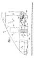
- FIG. 1is a partial top view of the left rear corner of a shuttle car embodying various features of the invention. Illustrated schematically in ghost is a motor, a cable, a cable reel, and the cable extending through a spooling device and then in between the sheaves of a hinged sheave bracket assembly. The cable then extends across the rear of the shuttle car when, for example, the shuttle car has made a right turn.
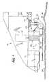
- FIG. 2is a view similar to FIG. 1 only showing the location of the hinged flexible bracket assembly and the cable as the shuttle car moves in a rearward direction.
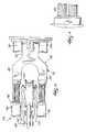
- FIG. 3is a partial perspective view of the flexible sheave bracket assembly shown in FIG. 2 .
- FIG. 4is a partial end view of the hinged sheave bracket assembly taken along the line 4 — 4 in FIG. 2 .
- FIG. 5is a partial side view of an arm including wire ropes welded to a pivot mount.
- this inventioncomprises a movable machine. More particularly, a shuttle car 10 useful in hauling material in underground mines is shown in FIG. 1 .
- the shuttle carincludes a frame 14 , an electrical motor 18 on the frame 14 , and a cable 22 ,electrically connected to the motor 18 and adapted to be connected to a source of power (not shown).
- the shuttle car 10further includes a reel 26 on the frame 14 between the electric motor 18 and one end of the frame 14 . More specifically, the reel 26 is located near the left rear 30 of the shuttle car 10 and the reel 26 provides for storage of the cable 22 . More particularly, as the shuttle car 10 moves backwards, forwards, and around corners, the cable 22 is either wound onto or paid out of a reel 26 .
- the cable 22extends from the rear 34 of the shuttle car 10 , and, at times, as shown in FIG. 2, either runs along the side 38 of the shuttle car 10 , when the shuttle car 10 is moving backwards, or extends straight back from the shuttle car 10 , when the shuttle car 10 is moving forward (not shown).
- the cable 22runs along the rear 34 of the shuttle car 10 .
- the cable 22can be between 500 and 750 feet long.
- the shuttle car 10further includes a spooling device 42 between the reel 26 and the rear 34 of the shuttle car 10 , and a sheave bracket assembly 46 mounted on the left rear 30 of the shuttle car 10 .
- the sheave bracket assembly 46includes a lower mounting plate 50 , and two spaced apart sheaves 54 and 58 rotatably mounted on the lower mounting plate 50 .
- the cable 22extends from the cable reel 26 through the spooling device 42 , and then between the sheaves 54 and 58 .
- the sheave bracket assembly 46further includes a second mounting plate 62 parallel to and spaced apart from the first mounting plate 50 .
- the two spaced apart sheaves 54 and 58are also rotatably mounted on the second mounting plate 62 between the two mounting plates 50 and 62 .
- the sheave bracket assembly 46further includes a hinged means 66 connecting the mounting plates 50 and 62 to the rear end 34 of the shuttle car 10 for permitting pivotal movement of the mounting plates relative to the frame 14 .
- the hinged means 66comprises an arm 70 having two ends, the arm including a first Y-shaped part with its base 74 attached to a first pivot mount 78 connecting the base to the rear end 34 of the shuttle car 10 .
- each upper Y piece 86 or 88includes four wire ropes 90 attached thereto by welding.
- the other end of the wire ropes 90are attached by welding (as shown in FIG. 5) to a second pivot mount 94 (see FIG. 4) connecting the wire ropes to the upper 62 and lower 50 mounting plates.
- the second pivot mount 94includes a lower pivot connection 96 to the first or lower mounting plate 50 and to one of the upper Y pieces 88 , and an upper pivot connection 98 to the second mounting plate 62 and to the other of the upper Y pieces 86 .
- the hinged means 66further includes a second arm 100 (see FIG. 3) having two ends, the second arm also including a first Y-shaped part with its base 102 attached to another first pivot mount 104 connecting the base 102 to the rear end 34 of the shuttle car 10 and each upper Y piece (only one shown) including four wire ropes attached thereto and attached to another second pivot mount 108 connecting the wire ropes to the upper and lower mounting plates 50 and 62 .
- the other second pivot mount 108also includes a lower pivot connection (not shown) to the first mounting plate 50 and to the lower one of the second arm upper Y pieces, and an upper pivot connection 110 to the second mounting plate 62 and to the upper one 112 of the second arm upper Y pieces.
- the frame left rear endis notched.
- the notchis formed by a first exterior wall and a second exterior wall extending perpendicular to the first exterior wall.
- the first arm 70 and a second arm 100are connected to the first wall, and the sheave bracket is located substantially within the notch.
- the sheave bracket assembly 46further includes a first resilient stop 114 attached to the rear end 34 of the shuttle car 10 adjacent the first pivot mount 78 , and a second resilient stop 118 attached to the rear end 34 of the shuttle car 10 adjacent the other side of the other first pivot mount 104 .
- the rearward most sheave 54Since the rearward most sheave 54 only needs to support the cable 22 through less than 90 degrees, while the other sheave 58 needs to support the cable through more than 90 degrees, the rearward most sheave 54 has a smaller diameter than the other sheave 58 .
Landscapes
- Engineering & Computer Science (AREA)
- Mechanical Engineering (AREA)
- Life Sciences & Earth Sciences (AREA)
- Sustainable Development (AREA)
- Sustainable Energy (AREA)
- Power Engineering (AREA)
- Transportation (AREA)
- Storing, Repeated Paying-Out, And Re-Storing Of Elongated Articles (AREA)
- Electric Cable Arrangement Between Relatively Moving Parts (AREA)
Abstract
Description
This invention relates to movable electric machinery having a trailing cable connected to a source of power. More particularly, this invention relates to a mechanism for preventing the cable from contacting the movable electrical machinery as the machinery moves forward, backwards, and around corners.
Movable electrical machinery, such as shuttle cars used for carrying mining material in underground mines, have electric motors connected by a cable to a source of power. As the machinery moves backwards, forwards, and around corners, the cable is either wound onto or paid out of a reel. The cable extends from the rear of the shuttle car, and, at times, either runs along the side of the shuttle car, when the shuttle car is moving backwards, or extends straight back from the shuttle car, when the shuttle car is moving forward. When the shuttle car moves around right corners, the cable runs along the rear of the shuttle car.
In order to prevent the cable contacting the side or the rear of the shuttle car, a two-sheave bracket assembly has been fixed on the left rear of the shuttle car. One sheave extends just beyond the rear most part of the shuttle car on one side of the shuttle car, and the second sheave, spaced from the first sheave, extends outward from the side of the shuttle car. In this manner, the cable either extends around one sheave and across the rear of the shuttle car when the shuttle car is making a 90-degree right turn, or the cable extends around the other sheave and back along the side of the shuttle car when the shuttle car is moving backwards. The current sheave bracket assembly arrangement is limited as to how far it can stick out of the side of the machine, otherwise the bracket assembly could be damaged by the bracket contacting the wall of the mine. Furthermore, the sheave bracket assembly cannot extend too much rearward of the shuttle car or it will affect the turning radius of the machine.
The invention provides a movable machine including a frame having an end, an electrical motor on the frame, a cable electrically connected to the motor and adapted to be connected to a source of power, and a sheave bracket assembly mounted on the frame end. The sheave bracket assembly includes a mounting plate, two spaced apart sheaves rotatably mounted on the mounting plate, the cable extending between the sheaves, and hinged means connecting the mounting plate to the frame end for permitting pivotal movement of the mounting plate relative to said frame.
More particularly, the invention provides a movable machine including a frame, an electrical motor on the frame, a cable electrically connected to the motor and adapted to be connected to a source of power, a reel on the frame between the electric motor and one end of the frame, the reel providing storage of the cable, a spooling device between the reel and the one frame end, and a sheave bracket assembly mounted on the one frame end. The sheave bracket assembly includes a mounting plate, and two spaced apart sheaves rotatably mounted on the mounting plate. The cable extends between the sheaves. A second mounting plate is parallel to and spaced apart from the first mounting plate, and the two spaced apart sheaves are also rotatably mounted on the second mounting plate.
The sheave bracket assembly also includes hinged means connecting the mounting plates to the frame end for permitting pivotal movement of the mounting plates relative to the frame. The hinged means comprises an arm including a first Y-shaped part with its base attached to a first pivot mount connecting its base to the frame end, and each upper Y piece includes four wire ropes attached thereto and attached to a second pivot mount connecting the four wire ropes to the mounting plate. The second pivot mount includes a lower pivot connection to the first mounting plate and to one of the upper Y pieces, and an upper pivot connection to the second mounting plate and to the other of the upper Y pieces.
The hinged means also includes a second arm including a first Y-shaped part with its base attached to another first pivot mount connecting its base to the frame end. Each upper Y piece includes four wire ropes attached thereto and attached to another second pivot mount connecting the four wire ropes to the mounting plate. This other second pivot mount includes a lower pivot connection to the first mounting plate and to one of the second arm upper Y pieces, and an upper pivot connection to the second mounting plate and to the other of the second arm upper Y pieces.
Still more particularly, the movable machine further includes a first resilient stop attached to the frame end adjacent the first pivot mount and a second resilient stop attached to the frame end adjacent the other side of the first pivot mount.
One of the principal objects of the invention is to provide a hinged sheave bracket assembly. A hinged sheave bracket assembly permits further extension of the sheave bracket assembly to the side of the shuttle car.
Another of the principal objects of the invention is to provide a hinged sheave bracket assembly mounted on flexible arms. The flexible arms reduce the stress put on the cable as the machine moves and changes direction. Further, if the sheave bracket assembly should engage the mine wall, the flexible arms help reduce the likelihood of damage to the sheave bracket assembly.
FIG. 1 is a partial top view of the left rear corner of a shuttle car embodying various features of the invention. Illustrated schematically in ghost is a motor, a cable, a cable reel, and the cable extending through a spooling device and then in between the sheaves of a hinged sheave bracket assembly. The cable then extends across the rear of the shuttle car when, for example, the shuttle car has made a right turn.
FIG. 2 is a view similar to FIG. 1 only showing the location of the hinged flexible bracket assembly and the cable as the shuttle car moves in a rearward direction.
FIG. 3 is a partial perspective view of the flexible sheave bracket assembly shown in FIG.2.
FIG. 4 is a partial end view of the hinged sheave bracket assembly taken along theline 4—4 in FIG.2.
FIG. 5 is a partial side view of an arm including wire ropes welded to a pivot mount.
Before the embodiments of the invention are explained in detail, it is to be understood that the invention is not limited in its application to the details of construction and the arrangements of the components set forth in the following description or illustrated in the drawings. The invention is capable of other embodiments and of being practiced or being carried out in various ways. Also, it is understood that the phraseology and terminology used herein are for the purpose of description and should not be regarded as limiting. The use of “including” and “comprising” and variations thereof herein is meant to encompass the items listed thereafter and equivalents thereof as well as additional items and equivalents thereof The use of “consisting of” and variations thereof herein is meant to encompass only the items listed thereafter and the equivalents thereof.
As illustrated in the drawings, this invention comprises a movable machine. More particularly, ashuttle car 10 useful in hauling material in underground mines is shown in FIG.1. The shuttle car includes aframe 14, anelectrical motor 18 on theframe 14, and a cable22,electrically connected to themotor 18 and adapted to be connected to a source of power (not shown). Theshuttle car 10 further includes areel 26 on theframe 14 between theelectric motor 18 and one end of theframe 14. More specifically, thereel 26 is located near the left rear30 of theshuttle car 10 and thereel 26 provides for storage of the cable22. More particularly, as theshuttle car 10 moves backwards, forwards, and around corners, the cable22 is either wound onto or paid out of areel 26. The cable22 extends from the rear34 of theshuttle car 10, and, at times, as shown in FIG. 2, either runs along theside 38 of theshuttle car 10, when theshuttle car 10 is moving backwards, or extends straight back from theshuttle car 10, when theshuttle car 10 is moving forward (not shown). When the shuttle car moves right around a corner, as shown in FIG. 1, the cable22 runs along the rear34 of theshuttle car 10. In many applications, the cable22 can be between 500 and 750 feet long.
Theshuttle car 10 further includes a spooling device42 between thereel 26 and the rear34 of theshuttle car 10, and asheave bracket assembly 46 mounted on the left rear30 of theshuttle car 10. As shown in FIGS. 3 and 4, thesheave bracket assembly 46 includes a lower mounting plate50, and two spaced apartsheaves 54 and58 rotatably mounted on the lower mounting plate50. As shown in FIGS. 1 and 2, the cable22 extends from thecable reel 26 through the spooling device42, and then between thesheaves 54 and58.
As shown in FIGS. 3 and 4, thesheave bracket assembly 46 further includes asecond mounting plate 62 parallel to and spaced apart from the first mounting plate50. The two spaced apartsheaves 54 and58 are also rotatably mounted on thesecond mounting plate 62 between the twomounting plates 50 and62.
In order to permit thesheave bracket assembly 46 to be small in size, but still prevent the cable22 from contacting either the rear34 of theshuttle car 10 or theside 38 of theshuttle car 10, thesheave bracket assembly 46 further includes ahinged means 66 connecting themounting plates 50 and62 to therear end 34 of theshuttle car 10 for permitting pivotal movement of the mounting plates relative to theframe 14. More particularly, thehinged means 66 comprises anarm 70 having two ends, the arm including a first Y-shaped part with itsbase 74 attached to afirst pivot mount 78 connecting the base to therear end 34 of theshuttle car 10.
In order to give the hingedmeans 66 some flexibility to help prevent damage to thesheave bracket assembly 46 in the event of the assembly contacting a mine wall82 (see FIG.2), and to help absorb shocks to theassembly 46 occasioned by changes in direction of the cable22, eachupper Y piece wire ropes 90 attached thereto by welding. The other end of thewire ropes 90 are attached by welding (as shown in FIG. 5) to a second pivot mount94 (see FIG. 4) connecting the wire ropes to the upper62 and lower50 mounting plates. More particularly, thesecond pivot mount 94 includes alower pivot connection 96 to the first or lower mounting plate50 and to one of theupper Y pieces 88, and anupper pivot connection 98 to thesecond mounting plate 62 and to the other of theupper Y pieces 86.
The hingedmeans 66 further includes a second arm100 (see FIG. 3) having two ends, the second arm also including a first Y-shaped part with itsbase 102 attached to anotherfirst pivot mount 104 connecting thebase 102 to therear end 34 of theshuttle car 10 and each upper Y piece (only one shown) including four wire ropes attached thereto and attached to anothersecond pivot mount 108 connecting the wire ropes to the upper andlower mounting plates 50 and62. More particularly, the othersecond pivot mount 108 also includes a lower pivot connection (not shown) to the first mounting plate50 and to the lower one of the second arm upper Y pieces, and an upper pivot connection110 to thesecond mounting plate 62 and to theupper one 112 of the second arm upper Y pieces.
More particularly, the frame left rear end is notched. The notch is formed by a first exterior wall and a second exterior wall extending perpendicular to the first exterior wall. Thefirst arm 70 and asecond arm 100 are connected to the first wall, and the sheave bracket is located substantially within the notch.
As shown in FIG. 1, in order to reduce the likelihood of contact between thearms shuttle car 10 causing damage to thearms sheave bracket assembly 46 further includes a firstresilient stop 114 attached to therear end 34 of theshuttle car 10 adjacent thefirst pivot mount 78, and a secondresilient stop 118 attached to therear end 34 of theshuttle car 10 adjacent the other side of the otherfirst pivot mount 104.
Since the rearward most sheave54 only needs to support the cable22 through less than 90 degrees, while the other sheave58 needs to support the cable through more than 90 degrees, the rearward most sheave54 has a smaller diameter than the other sheave58.
Several of the other features of the invention are set forth in the following.
Claims (38)
1. A movable machine including:
a frame having an end, said frame end having a first exterior wall,
an electrical motor on said frame,
a cable electrically connected to said motor and adapted to be connected to a source of power,
a sheave bracket assembly mounted on said frame end, said sheave bracket assembly including:
a mounting plate,
two spaced apart sheaves rotatably mounted on said mounting plate, said cable extending between said sheaves, and
hinged means connecting said mounting plate to said frame end first exterior wall for permitting pivotal movement of said mounting plate relative to said frame.
2. A movable machine in accordance withclaim 1 and further including a reel on said frame between said electric motor and said end of said frame, said reel providing storage of said cable, and
a spooling device between said reel and said frame end.
3. A movable machine in accordance withclaim 1 wherein said hinged means comprises:
an arm having two ends,
a first pivot mount connecting one arm end to said frame end, and
a second pivot mount connecting the other arm end to said mounting plate.
4. A movable machine in accordance withclaim 3 wherein said sheave bracket assembly further includes a second mounting plate parallel to and spaced apart from said first mounting plate, said two spaced apart sheaves also being rotatably mounted on said second mounting plate, and wherein said second pivot mount includes a lower pivot connection to said first mounting plate, and an upper pivot connection to said second mounting plate.
5. A movable machine in accordance withclaim 4 wherein said arm includes a first Y-shaped part, said Y-shaped part having a base and two upper Y-shaped pieces, with said base attached to the first pivot mount, and each upper Y piece including a wire rope attached thereto, and attached to a respective one of the second pivot mount upper and lower pivot connections.
6. A movable machine in accordance withclaim 5 wherein each upper Y piece includes four wire ropes attached thereto and attached to the respective one of the second pivot mount connections.
7. A movable machine in accordance withclaim 3 wherein said hinged means further includes:
a second arm spaced from said first arm and having two ends, another first pivot mount connecting said second arm one end to said frame end, and another second pivot mount connecting the other second arm end to said mounting plate.
8. A movable machine in accordance withclaim 7 wherein said sheave bracket assembly further includes a second mounting plate parallel to and spaced apart from said first mounting plate, said two spaced apart sheaves also being rotatably mounted on said second mounting plate, and wherein each of said second pivot mounts includes a lower pivot connection to said first mounting plate, and an upper pivot connection to said second mounting plate.
9. A movable machine in accordance withclaim 8 wherein said second arm includes a first Y-shaped part, said Y-shaped part having a base and two upper Y-shaped pieces, with said base attached to the first pivot mount, and each upper Y piece including a wire rope attached thereto and attached to a respective one of the second pivot mount upper and lower pivot connections.
10. A movable machine in accordance withclaim 9 wherein each upper Y piece includes four wire ropes attached thereto and attached to the respective one of the second pivot mounts.
11. A movable machine in accordance withclaim 1 and further including a first resilient stop attached to the frame end adjacent the first pivot mount and a second resilient stop attached to the frame end adjacent the other side of the first pivot mount.
12. A movable machine in accordance withclaim 1 and wherein one of said sheaves has a smaller diameter than the other sheave.
13. A movable machine in accordance withclaim 1 wherein said frame end has a notched corner, said notch being formed between said first exterior wall and a second exterior wall extending perpendicular to said first exterior wall, said sheave bracket being located substantially within said notch.
14. A movable machine in accordance withclaim 1 wherein said hinged means has a length about the same as the distance between the spaced apart sheaves.
15. A movable machine including:
a frame,
an electrical motor on said frame,
a cable electrically connected to said motor and adapted to be connected to a source of power,
a reel on said frame between said electric motor and one end of said frame, said reel providing storage of said cable,
a spooling device between said reel and said one frame end,
a sheave bracket assembly mounted on said one frame end, said sheave bracket assembly including:
a mounting plate,
two spaced apart sheaves rotatably mounted on said mounting plate, said cable extending between said sheaves, a second mounting plate parallel to and spaced apart from said first mounting plate, said two spaced apart sheaves also being rotatably mounted on said second mounting plate, and hinged means connecting said mounting plates to said frame end for permitting pivotal movement of said mounting plates relative to said frame, said hinged means comprising:
an arm including a first Y-shaped part, said Y-shaped part having a base and two upper Y-shaped pieces, with said base attached to a first pivot mount connecting its base to said frame end, and each upper Y piece including four wire ropes attached thereto and attached to a second pivot mount connecting the four wire ropes to said mounting plates, said second pivot mount including a lower pivot connection to said first mounting plate and to one of said upper Y pieces, and an upper pivot connection to said second mounting plate and to the other of said upper Y pieces,
a second arm also including a first Y-shaped part, said Y-shaped part having a base and two upper Y-shaped pieces, with said base attached to another first pivot mount connecting its base to said frame end, and each upper Y piece including four wire ropes attached thereto and attached to another second pivot mount connecting the four wire ropes to said mounting plates, said another second pivot mount including a lower pivot connection to said first mounting plate and to one of said second arm upper Y pieces, and an upper pivot connection to said second mounting plate and to the other of said second arm upper Y pieces.
16. A movable machine in accordance withclaim 15 and further including a first resilient stop attached to the frame end adjacent the first pivot mount and a second resilient stop attached to the frame end adjacent the other side of the first pivot mount.
17. A movable machine in accordance withclaim 15 and wherein one of said sheaves has a smaller diameter than the other sheave.
18. A movable machine including:
a frame having an end,
an electrical motor on said frame,
a cable electrically connected to said motor and adapted to be connected to a source of power,
a sheave bracket assembly mounted on said frame end, said sheave bracket assembly including:
a mounting plate,
two spaced apart sheaves rotatably mounted on said mounting plate, said cable extending between said sheaves, and
hinged means connecting said mounting plate to said frame end for permitting pivotal movement of said mounting plate relative to said frame, said hinged means including
an arm having two ends,
a first pivot mount connecting one arm end to said frame end, and
a second pivot mount connecting the other arm end to said mounting plate, and
a second arm spaced from said first arm and having two ends, another first pivot mount connecting said second arm one end to said frame end, and another second pivot mount connecting the other second arm end to said mounting plate.
19. A movable machine in accordance withclaim 18 and further including a reel on said frame between said electric motor and said end of said frame, said reel providing storage of said cable, and
a spooling device between said reel and said frame end.
20. A movable machine in accordance withclaim 18 wherein said sheave bracket assembly further includes a second mounting plate parallel to and spaced apart from said first mounting plate, said two spaced apart sheaves also being rotatably mounted on said second mounting plate, and wherein said second pivot mount includes a lower pivot connection to said first mounting plate, and an upper pivot connection to said second mounting plate.
21. A movable machine in accordance withclaim 20 wherein said arm includes a first Y-shaped part, said Y-shaped part having a base and two upper Y-shaped pieces, with said base attached to the first pivot mount, and each upper Y piece including a wire rope attached thereto, and attached to a respective one of the second pivot mount upper and lower pivot connections.
22. A movable machine in accordance withclaim 21 wherein each upper Y piece includes four wire ropes attached thereto and attached to the respective one of the second pivot mount connections.
23. A movable machine in accordance withclaim 22 wherein said sheave bracket assembly further includes a second mounting plate parallel to and spaced apart from said first mounting plate, said two spaced apart sheaves also being rotatably mounted on said second mounting plate, and wherein each of said second pivot mounts includes a lower pivot connection to said first mounting plate, and an upper pivot connection to said second mounting plate.
24. A movable machine in accordance withclaim 23 wherein said second arm includes a first Y-shaped part, said Y-shaped part having a base and two upper Y-shaped pieces, with said base attached to the first pivot mount, and each upper Y piece including a wire rope attached thereto and attached to a respective one of the second pivot mount upper and lower pivot connections.
25. A movable machine in accordance withclaim 24 wherein each upper Y piece includes four wire ropes attached thereto and attached to the respective one of the second pivot mounts.
26. A movable machine in accordance withclaim 18 and further including a first resilient stop attached to the frame end adjacent the first pivot mount and a second resilient stop attached to the frame end adjacent the other side of the first pivot mount.
27. A movable machine in accordance withclaim 18 and wherein one of said sheaves has a smaller diameter than the other sheave.
28. A movable machine including:
a frame having an end,
an electrical motor on said frame,
a cable electrically connected to said motor and adapted to be connected to a source of power,
a sheave bracket assembly mounted on said frame end, said sheave bracket assembly including:
a mounting plate,
two spaced apart sheaves rotatably mounted on said mounting plate, one of said sheaves having a smaller diameter than the other sheave, and said cable extends between said sheaves, and
hinged means connecting said mounting plate to said frame end for permitting pivotal movement of said mounting plate relative to said frame.
29. A movable machine in accordance withclaim 28 and further including a reel on said frame between said electric motor and said end of said frame, said reel providing storage of said cable, and
a spooling device between said reel and said frame end.
30. A movable machine in accordance withclaim 28 wherein said hinged means comprises:
an arm having two ends,
a first pivot mount connecting one arm end to said frame end, and
a second pivot mount connecting the other arm end to said mounting plate.
31. A movable machine in accordance withclaim 30 wherein said sheave bracket assembly further includes a second mounting plate parallel to and spaced apart from said first mounting plate, said two spaced apart sheaves also being rotatably mounted on said second mounting plater and wherein said second pivot mount includes a lower pivot connection to said first mounting plate, and an upper pivot connection to said second mounting plate.
32. A movable machine in accordance withclaim 31 wherein said arm includes a first Y-shaped part, said Y-shaped part having a base and two upper Y-shaped pieces, with said base attached to the first pivot mount, and each upper Y piece including a wire rope attached thereto, and attached to a respective one of the second pivot mount upper and lower pivot connections.
33. A movable machine in accordance withclaim 32 wherein each upper Y piece includes four wire ropes attached thereto and attached to the respective one of the second pivot mount connections.
34. A movable machine in accordance withclaim 30 wherein said hinged means further includes:
a second arm spaced from said first arm and having two ends, another first pivot mount connecting said second arm one end to said frame end, and another second pivot mount connecting the other second arm end to said mounting plate.
35. A movable machine in accordance withclaim 34 wherein said sheave bracket assembly further includes a second mounting plate parallel to and spaced apart from said first mounting plate, said two spaced apart sheaves also being rotatably mounted on said second mounting plate, and wherein each of said second pivot mounts includes a lower pivot connection to said first mounting plate, and an upper pivot connection to said second mounting plate.
36. A movable machine in accordance withclaim 35 wherein said second arm includes a first Y-shaped part, said Y-shaped part having a base and two upper Y-shaped pieces, with said base attached to the first pivot mount, and each upper Y piece including a wire rope attached thereto and attached to a respective one of the second pivot mount upper and lower pivot connections.
37. A movable machine in accordance withclaim 36 wherein each upper Y piece includes four wire ropes attached thereto and attached to the respective one of the second pivot mounts.
38. A movable machine in accordance withclaim 28 and further including a first resilient stop attached to the frame end adjacent the first pivot mount and a second resilient stop attached to the frame end adjacent the other side of the first pivot mount.
Priority Applications (3)
| Application Number | Priority Date | Filing Date | Title |
|---|---|---|---|
| US09/681,165US6530537B2 (en) | 2001-02-07 | 2001-02-07 | Movable electric machinery having a trailing cable extending through a hinged sheave bracket assembly |
| AU10160/02AAU783353B2 (en) | 2001-02-07 | 2002-01-14 | Machinery having a trailing cable extending through a hinged sheave bracket assembly |
| ZA200200566AZA200200566B (en) | 2001-02-07 | 2002-01-22 | Movable electric machinery having a trailing cable extending through a hinged sheave bracket assembly. |
Applications Claiming Priority (1)
| Application Number | Priority Date | Filing Date | Title |
|---|---|---|---|
| US09/681,165US6530537B2 (en) | 2001-02-07 | 2001-02-07 | Movable electric machinery having a trailing cable extending through a hinged sheave bracket assembly |
Publications (2)
| Publication Number | Publication Date |
|---|---|
| US20020104915A1 US20020104915A1 (en) | 2002-08-08 |
| US6530537B2true US6530537B2 (en) | 2003-03-11 |
Family
ID=24734115
Family Applications (1)
| Application Number | Title | Priority Date | Filing Date |
|---|---|---|---|
| US09/681,165Expired - LifetimeUS6530537B2 (en) | 2001-02-07 | 2001-02-07 | Movable electric machinery having a trailing cable extending through a hinged sheave bracket assembly |
Country Status (3)
| Country | Link |
|---|---|
| US (1) | US6530537B2 (en) |
| AU (1) | AU783353B2 (en) |
| ZA (1) | ZA200200566B (en) |
Cited By (18)
| Publication number | Priority date | Publication date | Assignee | Title |
|---|---|---|---|---|
| US20060106714A1 (en)* | 1999-09-21 | 2006-05-18 | Intertrust Technologies Corporation | Systems and methods for pricing and selling digital goods |
| US20060280584A1 (en)* | 2005-05-27 | 2006-12-14 | Corey Spuzak | Lift attachment for an ATV |
| US20070063875A1 (en)* | 1998-01-27 | 2007-03-22 | Hoffberg Steven M | Adaptive pattern recognition based controller apparatus and method and human-factored interface therefore |
| US20070087756A1 (en)* | 2005-10-04 | 2007-04-19 | Hoffberg Steven M | Multifactorial optimization system and method |
| US20100300826A1 (en)* | 2009-05-29 | 2010-12-02 | Joy Mm Delaware | Non-conductive trailing cable guide |
| US20110089284A1 (en)* | 2009-09-18 | 2011-04-21 | Dean Bartolone | Cable tensioning device |
| US20110184597A1 (en)* | 2010-01-22 | 2011-07-28 | Joy Mm Delaware, Inc. | Device for reducing the likelihood of damage to a trailing cable |
| US8016102B2 (en) | 2000-10-06 | 2011-09-13 | The Cincinnati Mine Machinery Company | Conveyor chain for mining machinery |
| US8453826B2 (en) | 2008-09-22 | 2013-06-04 | The Cincinnati Mine Machinery Company | Conveyor chain |
| US20130146410A1 (en)* | 2011-12-13 | 2013-06-13 | Joy Mm Delaware, Inc. | Swinging sheave bracket with force control |
| US20130228386A1 (en)* | 2011-08-01 | 2013-09-05 | Joy Mm Delaware, Inc. | Low friction sheave bracket |
| US8600830B2 (en) | 2003-02-05 | 2013-12-03 | Steven M. Hoffberg | System and method for providing a payment to a non-winning auction participant |
| US20140265519A1 (en)* | 2013-03-14 | 2014-09-18 | Seneca Industries Inc. | Mining methods and equipment |
| US8936146B2 (en) | 2008-09-22 | 2015-01-20 | The Cincinnati Mine Machinery Company | Conveyor chain |
| US9227787B2 (en) | 2008-09-22 | 2016-01-05 | The Cincinnati Mine Machinery Company | Conveyor chain |
| US9311670B2 (en) | 2004-09-10 | 2016-04-12 | Steven M. Hoffberg | Game theoretic prioritization system and method |
| US9487358B2 (en) | 2008-09-22 | 2016-11-08 | The Cincinnati Mine Machinery Company | Conveyor chain |
| US10875717B2 (en) | 2008-09-22 | 2020-12-29 | The Cincinnati Mine Machinery Company | Conveyor chain |
Families Citing this family (4)
| Publication number | Priority date | Publication date | Assignee | Title |
|---|---|---|---|---|
| US7717402B2 (en)* | 2007-06-07 | 2010-05-18 | Mann Samuel J | Line handling winch for sailing yachts |
| JP5182996B2 (en) | 2011-02-21 | 2013-04-17 | 株式会社豊田自動織機 | Vehicle charging device |
| CN105121048A (en)* | 2012-12-14 | 2015-12-02 | 乔伊·姆·特拉华公司 | Shuttle car spring-assisted swing pulley bracket |
| CN105692352A (en)* | 2016-03-30 | 2016-06-22 | 云南电网有限责任公司昆明供电局 | Electric vertical drum type ground wire winding and unwinding device |
Citations (8)
| Publication number | Priority date | Publication date | Assignee | Title |
|---|---|---|---|---|
| US2458573A (en)* | 1945-06-18 | 1949-01-11 | Donahue Howard | Insulated cable and rope spooling guide |
| US3061233A (en)* | 1958-05-29 | 1962-10-30 | Joy Mfg Co | Reeling device |
| US4047599A (en)* | 1976-05-11 | 1977-09-13 | Victor Rousseau | Electrically powered vehicle and feed cart |
| US4569489A (en)* | 1984-04-27 | 1986-02-11 | Joy Manufacturing Company | Cable tension control device |
| US4583700A (en)* | 1981-07-03 | 1986-04-22 | Aleksei Tschurbanoff | Cable winding system for electrically powered mine vehicles |
| US4982057A (en)* | 1989-09-11 | 1991-01-01 | Pyro Mining Company | Batwing for a shuttle car |
| JPH0647439A (en)* | 1992-08-04 | 1994-02-22 | Nippon Steel Corp | Coil fall prevention device |
| US6119837A (en)* | 1996-02-02 | 2000-09-19 | Tamrock Oy | Method and arrangement for controlling cable winding and unwinding in an electrically driven vehicle |
- 2001
- 2001-02-07USUS09/681,165patent/US6530537B2/ennot_activeExpired - Lifetime
- 2002
- 2002-01-14AUAU10160/02Apatent/AU783353B2/ennot_activeCeased
- 2002-01-22ZAZA200200566Apatent/ZA200200566B/enunknown
Patent Citations (8)
| Publication number | Priority date | Publication date | Assignee | Title |
|---|---|---|---|---|
| US2458573A (en)* | 1945-06-18 | 1949-01-11 | Donahue Howard | Insulated cable and rope spooling guide |
| US3061233A (en)* | 1958-05-29 | 1962-10-30 | Joy Mfg Co | Reeling device |
| US4047599A (en)* | 1976-05-11 | 1977-09-13 | Victor Rousseau | Electrically powered vehicle and feed cart |
| US4583700A (en)* | 1981-07-03 | 1986-04-22 | Aleksei Tschurbanoff | Cable winding system for electrically powered mine vehicles |
| US4569489A (en)* | 1984-04-27 | 1986-02-11 | Joy Manufacturing Company | Cable tension control device |
| US4982057A (en)* | 1989-09-11 | 1991-01-01 | Pyro Mining Company | Batwing for a shuttle car |
| JPH0647439A (en)* | 1992-08-04 | 1994-02-22 | Nippon Steel Corp | Coil fall prevention device |
| US6119837A (en)* | 1996-02-02 | 2000-09-19 | Tamrock Oy | Method and arrangement for controlling cable winding and unwinding in an electrically driven vehicle |
Cited By (39)
| Publication number | Priority date | Publication date | Assignee | Title |
|---|---|---|---|---|
| US9551582B2 (en) | 1998-01-27 | 2017-01-24 | Blanding Hovenweep, Llc | Mobile communication device |
| US20070063875A1 (en)* | 1998-01-27 | 2007-03-22 | Hoffberg Steven M | Adaptive pattern recognition based controller apparatus and method and human-factored interface therefore |
| US8373582B2 (en) | 1998-01-27 | 2013-02-12 | Steven M. Hoffberg | Adaptive pattern recognition based controller apparatus and method and human-factored interface therefore |
| US10127816B2 (en) | 1998-01-27 | 2018-11-13 | Blanding Hovenweep, Llc | Detection and alert of automobile braking event |
| US20060178980A1 (en)* | 1999-09-21 | 2006-08-10 | Intertrust Technologies Corporation | Systems and methods for pricing and selling digital goods |
| US20060106714A1 (en)* | 1999-09-21 | 2006-05-18 | Intertrust Technologies Corporation | Systems and methods for pricing and selling digital goods |
| US8355978B2 (en) | 1999-09-21 | 2013-01-15 | Intertrust Technologies Corp. | Systems and methods for pricing and selling digital goods |
| US7933829B2 (en)* | 1999-09-21 | 2011-04-26 | Intertrust Technologies Corp. | Systems and methods for pricing and selling digital goods |
| US8016102B2 (en) | 2000-10-06 | 2011-09-13 | The Cincinnati Mine Machinery Company | Conveyor chain for mining machinery |
| US8448781B2 (en) | 2000-10-06 | 2013-05-28 | The Cincinnati Mine Machinery Co., Inc. | Conveyor chain for mining machinery |
| US8600830B2 (en) | 2003-02-05 | 2013-12-03 | Steven M. Hoffberg | System and method for providing a payment to a non-winning auction participant |
| US9818136B1 (en) | 2003-02-05 | 2017-11-14 | Steven M. Hoffberg | System and method for determining contingent relevance |
| US10943273B2 (en) | 2003-02-05 | 2021-03-09 | The Hoffberg Family Trust 2004-1 | System and method for determining contingent relevance |
| US11790413B2 (en) | 2003-02-05 | 2023-10-17 | Hoffberg Family Trust 2 | System and method for communication |
| US9311670B2 (en) | 2004-09-10 | 2016-04-12 | Steven M. Hoffberg | Game theoretic prioritization system and method |
| US20060280584A1 (en)* | 2005-05-27 | 2006-12-14 | Corey Spuzak | Lift attachment for an ATV |
| US10567975B2 (en) | 2005-10-04 | 2020-02-18 | Hoffberg Family Trust 2 | Multifactorial optimization system and method |
| USRE49334E1 (en) | 2005-10-04 | 2022-12-13 | Hoffberg Family Trust 2 | Multifactorial optimization system and method |
| US8874477B2 (en) | 2005-10-04 | 2014-10-28 | Steven Mark Hoffberg | Multifactorial optimization system and method |
| US20070087756A1 (en)* | 2005-10-04 | 2007-04-19 | Hoffberg Steven M | Multifactorial optimization system and method |
| US10315849B2 (en) | 2008-09-22 | 2019-06-11 | The Cincinnati Mine Machinery Company | Conveyor chain |
| US8936146B2 (en) | 2008-09-22 | 2015-01-20 | The Cincinnati Mine Machinery Company | Conveyor chain |
| US10875717B2 (en) | 2008-09-22 | 2020-12-29 | The Cincinnati Mine Machinery Company | Conveyor chain |
| US9227787B2 (en) | 2008-09-22 | 2016-01-05 | The Cincinnati Mine Machinery Company | Conveyor chain |
| US8453826B2 (en) | 2008-09-22 | 2013-06-04 | The Cincinnati Mine Machinery Company | Conveyor chain |
| US9487358B2 (en) | 2008-09-22 | 2016-11-08 | The Cincinnati Mine Machinery Company | Conveyor chain |
| US20100300826A1 (en)* | 2009-05-29 | 2010-12-02 | Joy Mm Delaware | Non-conductive trailing cable guide |
| US20110089284A1 (en)* | 2009-09-18 | 2011-04-21 | Dean Bartolone | Cable tensioning device |
| US8989929B2 (en) | 2010-01-22 | 2015-03-24 | Joy Mm Delaware, Inc. | Device for reducing the likelihood of damage to a trailing cable |
| US20110184597A1 (en)* | 2010-01-22 | 2011-07-28 | Joy Mm Delaware, Inc. | Device for reducing the likelihood of damage to a trailing cable |
| US20130228386A1 (en)* | 2011-08-01 | 2013-09-05 | Joy Mm Delaware, Inc. | Low friction sheave bracket |
| US8985289B2 (en)* | 2011-08-01 | 2015-03-24 | Joy Mm Delaware, Inc. | Low friction sheave bracket |
| US9221651B2 (en)* | 2011-12-13 | 2015-12-29 | Joy Mm Delaware, Inc. | Swinging sheave bracket with force control |
| US20130146410A1 (en)* | 2011-12-13 | 2013-06-13 | Joy Mm Delaware, Inc. | Swinging sheave bracket with force control |
| US9617852B2 (en) | 2013-03-14 | 2017-04-11 | Seneca Industries Inc. | Mining systems |
| US9010870B2 (en) | 2013-03-14 | 2015-04-21 | Seneca Industries Inc. | Mining systems |
| US8985699B2 (en) | 2013-03-14 | 2015-03-24 | Seneca Industries Inc. | Mining methods and equipment |
| US8985700B2 (en)* | 2013-03-14 | 2015-03-24 | Seneca Industries Inc. | Mining systems with guidance systems |
| US20140265519A1 (en)* | 2013-03-14 | 2014-09-18 | Seneca Industries Inc. | Mining methods and equipment |
Also Published As
| Publication number | Publication date |
|---|---|
| ZA200200566B (en) | 2002-07-31 |
| AU1016002A (en) | 2002-08-08 |
| US20020104915A1 (en) | 2002-08-08 |
| AU783353B2 (en) | 2005-10-20 |
Similar Documents
| Publication | Publication Date | Title |
|---|---|---|
| US6530537B2 (en) | Movable electric machinery having a trailing cable extending through a hinged sheave bracket assembly | |
| US9221651B2 (en) | Swinging sheave bracket with force control | |
| JPS5883517A (en) | Cable sinding device for motor driven vehicle in tunnel | |
| BR9907018A (en) | Mounting of motorized retractable stirrup for a motor vehicle. | |
| WO2018006666A1 (en) | Open-type electric pallet truck | |
| US11091081B1 (en) | Crane mat lift | |
| US20140166419A1 (en) | Shuttle car spring-assisted swinging sheave bracket | |
| ZA201003536B (en) | Non-conductive trailing cable guide | |
| US3696240A (en) | Light fixture for a loading dock | |
| US12054910B2 (en) | Work vehicle | |
| JP6727545B2 (en) | Mobile crane hook block storage | |
| JP2004256206A (en) | Self-propelled conveyor | |
| CN210100055U (en) | A self-protecting industrial robot | |
| US6749267B1 (en) | Truck bed dumping system | |
| AU2007202415A1 (en) | Improvement relating to mining vehicles | |
| JP2003039373A (en) | Industrial robot | |
| CN219371367U (en) | Marine antenna device | |
| JP6905100B2 (en) | Cargo handling vehicle | |
| JP2001302174A (en) | Cable routing structure to mobile cab | |
| CN216983328U (en) | Pencil receiving mechanism and pancake baking machine with same | |
| JPH0620794Y2 (en) | Aerial work vehicle | |
| JPH07157010A (en) | Cable housing device for crane | |
| JP2857018B2 (en) | Backhoe boom structure | |
| JP4545546B2 (en) | Lifting magnet cable mounting structure | |
| JP2912567B2 (en) | Retractable short jib |
Legal Events
| Date | Code | Title | Description |
|---|---|---|---|
| AS | Assignment | Owner name:JOY MM DELAWARE, INC., DELAWARE Free format text:ASSIGNMENT OF ASSIGNORS INTEREST;ASSIGNOR:HANLON, RONALD D.;REEL/FRAME:011814/0135 Effective date:20010130 | |
| AS | Assignment | Owner name:BANKERS TRUST COMPANY, AS AGENT, NEW YORK Free format text:SECURITY INTEREST;ASSIGNOR:JOY MM DELAWARE, INC., A DELAWARE CORPORATION;REEL/FRAME:011979/0729 Effective date:20010629 | |
| STCF | Information on status: patent grant | Free format text:PATENTED CASE | |
| FPAY | Fee payment | Year of fee payment:4 | |
| FPAY | Fee payment | Year of fee payment:8 | |
| FPAY | Fee payment | Year of fee payment:12 | |
| AS | Assignment | Owner name:JOY GLOBAL UNDERGROUND MINING LLC, PENNSYLVANIA Free format text:MERGER;ASSIGNOR:JOY MM DELAWARE, INC.;REEL/FRAME:047096/0399 Effective date:20180430 |