US6530032B1 - Network fault recovery method and apparatus - Google Patents
Network fault recovery method and apparatusDownload PDFInfo
- Publication number
- US6530032B1 US6530032B1US09/401,919US40191999AUS6530032B1US 6530032 B1US6530032 B1US 6530032B1US 40191999 AUS40191999 AUS 40191999AUS 6530032 B1US6530032 B1US 6530032B1
- Authority
- US
- United States
- Prior art keywords
- path
- layer
- network
- cut
- router
- Prior art date
- Legal status (The legal status is an assumption and is not a legal conclusion. Google has not performed a legal analysis and makes no representation as to the accuracy of the status listed.)
- Expired - Lifetime
Links
Images


Classifications
- H—ELECTRICITY
- H04—ELECTRIC COMMUNICATION TECHNIQUE
- H04L—TRANSMISSION OF DIGITAL INFORMATION, e.g. TELEGRAPHIC COMMUNICATION
- H04L45/00—Routing or path finding of packets in data switching networks
- H04L45/22—Alternate routing
- H—ELECTRICITY
- H04—ELECTRIC COMMUNICATION TECHNIQUE
- H04L—TRANSMISSION OF DIGITAL INFORMATION, e.g. TELEGRAPHIC COMMUNICATION
- H04L41/00—Arrangements for maintenance, administration or management of data switching networks, e.g. of packet switching networks
- H04L41/06—Management of faults, events, alarms or notifications
- H04L41/0654—Management of faults, events, alarms or notifications using network fault recovery
- H04L41/0663—Performing the actions predefined by failover planning, e.g. switching to standby network elements
- H—ELECTRICITY
- H04—ELECTRIC COMMUNICATION TECHNIQUE
- H04L—TRANSMISSION OF DIGITAL INFORMATION, e.g. TELEGRAPHIC COMMUNICATION
- H04L43/00—Arrangements for monitoring or testing data switching networks
- H04L43/08—Monitoring or testing based on specific metrics, e.g. QoS, energy consumption or environmental parameters
- H04L43/0805—Monitoring or testing based on specific metrics, e.g. QoS, energy consumption or environmental parameters by checking availability
- H04L43/0811—Monitoring or testing based on specific metrics, e.g. QoS, energy consumption or environmental parameters by checking availability by checking connectivity
- H—ELECTRICITY
- H04—ELECTRIC COMMUNICATION TECHNIQUE
- H04L—TRANSMISSION OF DIGITAL INFORMATION, e.g. TELEGRAPHIC COMMUNICATION
- H04L45/00—Routing or path finding of packets in data switching networks
- H04L45/28—Routing or path finding of packets in data switching networks using route fault recovery
- H—ELECTRICITY
- H04—ELECTRIC COMMUNICATION TECHNIQUE
- H04L—TRANSMISSION OF DIGITAL INFORMATION, e.g. TELEGRAPHIC COMMUNICATION
- H04L45/00—Routing or path finding of packets in data switching networks
- H04L45/50—Routing or path finding of packets in data switching networks using label swapping, e.g. multi-protocol label switch [MPLS]
- H—ELECTRICITY
- H04—ELECTRIC COMMUNICATION TECHNIQUE
- H04L—TRANSMISSION OF DIGITAL INFORMATION, e.g. TELEGRAPHIC COMMUNICATION
- H04L49/00—Packet switching elements
- H04L49/55—Prevention, detection or correction of errors
- H04L49/557—Error correction, e.g. fault recovery or fault tolerance
- H—ELECTRICITY
- H04—ELECTRIC COMMUNICATION TECHNIQUE
- H04L—TRANSMISSION OF DIGITAL INFORMATION, e.g. TELEGRAPHIC COMMUNICATION
- H04L69/00—Network arrangements, protocols or services independent of the application payload and not provided for in the other groups of this subclass
- H04L69/40—Network arrangements, protocols or services independent of the application payload and not provided for in the other groups of this subclass for recovering from a failure of a protocol instance or entity, e.g. service redundancy protocols, protocol state redundancy or protocol service redirection
- H—ELECTRICITY
- H04—ELECTRIC COMMUNICATION TECHNIQUE
- H04L—TRANSMISSION OF DIGITAL INFORMATION, e.g. TELEGRAPHIC COMMUNICATION
- H04L49/00—Packet switching elements
- H04L49/25—Routing or path finding in a switch fabric
- H04L49/251—Cut-through or wormhole routing
- H—ELECTRICITY
- H04—ELECTRIC COMMUNICATION TECHNIQUE
- H04L—TRANSMISSION OF DIGITAL INFORMATION, e.g. TELEGRAPHIC COMMUNICATION
- H04L49/00—Packet switching elements
- H04L49/60—Software-defined switches
- H04L49/602—Multilayer or multiprotocol switching, e.g. IP switching
Definitions
- the present inventionrelates to network fault recovery method and apparatus and is particularly concerned with recovery at higher layers from physical layer faults.
- a faster solution conventionally used to protect network connectionsconsists of implementing protection in the physical layer (layer 1 ) of the network by installing redundant equipment so that if one physical link fails, another can rapidly be switched into place.
- Redundancy of equipmenthas long been accepted by carrier grade networks as a way to ensure availability and reliability.
- networks not requiring carrier grade protectionstill desire rapid recovery from physical failures, particularly in high throughput links such as carried in optical fiber, e.g. OC-192.
- An object of the present inventionis to provide an improved network fault recovery method and apparatus.
- L 1 /L 2 /L 3 Integration and L 1 cut-through path utilizationare provided in an apparatus and method of fault recovery.
- a switchwhich combines an IP router with L 2 capabilities, and an L 1 cross connect (optical or electrical).
- a networkin which switches are configured with label switched paths (LSPS) that correspond to layer 1 (L 1 ) cut-through paths.
- LSPSlabel switched paths
- a layer 2 (L 2 ) cut-through pathis over laid on the L 1 cut-through path and the L 2 cut-through path is used for IP data flows.
- the L 2 cut-through pathsare defined as label switched paths (LSPs).
- LSPslabel switched paths
- L 1 cut-through pathsare each an end-to-end path established with L 1 cross connects associated with each switch.
- a methodis provided in which upon failure of a physical link, all LSP endpoints associated with affected L 1 cut-through paths are notified by physical detection methods.
- label switch pathsare defined corresponding to a respective L 1 cut-through path
- the MPLS entity managing an LSPis notified of LSP failures that correspond to L 1 cut-through path failure, and backup procedures are then executed to restore IP forwarding.
- a method of fault recovery for a networkincluding the steps of establishing a physical topology for the network, aligning a logical topology for the network with the physical topology, and using a fault indication from the physical topology to effect fault recovery in the logical topology.
- an apparatus for data networkingcomprising a cross connect for switching at a physical layer, a router for redirecting data packets at a logical layer coupled to the cross connect, and a fault recovery mechanism responsive to a fault indication in the physical layer for effecting a recovery in the logical layer.
- the routerincludes an internetworking protocol (IP).
- IPinternetworking protocol
- the internetworking protocolincludes multi-protocol label switching (MPLS).
- MPLSmulti-protocol label switching
- a networkcomprising a plurality of nodes, each node including a cross connect for switching at a physical layer, a router for redirecting data packets at a logical layer coupled to the cross connect and a fault recovery mechanism responsive to a fault indication in the physical layer for effecting a recovery in the logical layer, a plurality of physical connections between nodes via the respective cross connects, a plurality of logical routes between nodes via the respective routers, and an alternative logical route for use by the fault recovery mechanism.
- a method of providing fault recoverycomprising the steps of aligning at least a first and second layer of the plurality of communications layers, for a given path in the first layer, defining a corresponding path in the second layer and an alternative path in the second layer, the alternative path in the second layer corresponding to an alternative path in the first layer disjoint from the given path, and on detection in the first layer of a fault in the given path, switching in the second layer from the corresponding path to the alternative path, whereby fault recovery in the network is provided
- Advantages of the present inventioninclude faster recovery from layer 1 failure than provided by L 3 routing algorithms and integration of the layers 1 , 2 and 3 networks into a common topology (a network management simplification and potential equipment cost saving).
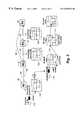
- FIG. 1illustrates a known ATM link between two label switched routers (LSR);
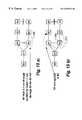
- FIGS. 2 a ) and b )illustrate a network of four routers showing topology and label switched paths respectively;
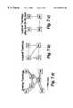
- FIGS. 3 a ), b ) and c )illustrate a physical topology, L 3 links and OSPF topology, respectively;
- FIG. 4illustrates connectionless layer 3 internet protocol (IP) forwarding in a network of four routers
- FIG. 5illustrates label switching in a network of four label switching routers
- FIGS. 6 a ), b ) and c )illustrate routers on SONET ring and how they are typically connected;
- FIGS. 7 a ), b ), and cillustrate routers in a TDM overlay
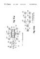
- FIGS. 8 a ), b ), and cillustrate a switch in accordance with a first embodiment of the present invention and a physical and logical topologies for two such switches;
- FIGS. 9 a ) and b )illustrate an exemplary network's physical and router topologies made up of switches of FIG. 8;
- FIGS. 10 a ) and b )illustrate the network of FIG. 9 a ) and b ) showing a layer 1 (L 1 ) cut-through path.
- a layer 1 cross connected pathis treated as a layer 1 cut-through path by the routers;
- FIGS. 11 a ) and b )illustrate IP packet forwarding using the L 1 cut-through path of FIG. 10 b );
- FIGS. 12 a ) and b )illustrate the effect of an L 1 link failure on the use of layer 1 cut-through path by L 3 forwarding
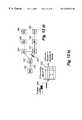
- FIG. 13illustrates a series of L 1 cut-through paths based on the FIG. 10 topology
- FIGS. 14 a ) and b )illustrate an L 1 failure in the network of FIG. 13, and the L 3 routing view from the point of router R 5 ;
- FIGS. 15 a ) and b )illustrate the network topology of FIG. 14 a ) showing only the L 1 cut-through path not affected by the failed link and an LSP set up using the L 1 cut-through path, respectively;
- FIGS. 16 a ) and b )illustrate routing tables, label tables and cross-connects for the topology of FIG. 15 b ), and illustrate how data is forwarded on a recovery LSP that uses an L 1 cut-through path;
- FIG. 17illustrates an L 3 stabilised topology database view after the failure has been used to update the L 3 routing tables throughout the network
- FIG. 18illustrates how a router recovers from the failure of a second L 1 cut-through path affected by the failure of FIG. 14;
- FIGS. 19 a ) and b )illustrate a network topology when the failed L 1 link recovers and L 1 cut-through paths are automatically re-established by original configuration information, respectively.
- An ATM link 10runs between LSR 12 and LSR 14 and as shown in the expanded link section 16 , an ATM link typically carries both connectionless traffic 18 and connection oriented traffic such as MPLS label switched paths 20 and 22 .
- control and data planesare typically not separated.
- IP Control Trafficconsists of:
- Routing protocol messagessuch as OSPF Hello, OSPF Link State Advertisements
- IP Data Trafficconsists of:
- Network-to-network datawhich is carried in TCP or UDP packets (e.g., BGP 4 updates)
- TCP or UDP packetse.g., BGP 4 updates
- Typical router-router links 10carry both control and data traffic, 18 . It is possible to separate IP control and data streams. This could be on separate links or could be on separate channels within a channeled link like ATM.
- IP routing controlis done in a connectionless manner
- IP datacan be forwarded on Label Switched Paths that are in different channels than IP connectionless control.
- FIGS. 2 a ) and b )there are illustrated a network of four routers showing router topology and label switched paths, respectively.
- routers 30 , 32 , 34 and 36are connected by: physical link 38 between routers 30 and 32 ; physical link 40 between routers 30 and 34 ; and physical link 42 between routers 30 and 36 .
- FIG. 2 arouters 30 , 32 , 34 and 36 are connected by: physical link 38 between routers 30 and 32 ; physical link 40 between routers 30 and 34 ; and physical link 42 between routers 30 and 36 .
- routers 30 , 32 , 34 and 36are interconnected by: MPLS label switched path (LSP) 50 between routers 30 and 32 ; LSP 52 between routers 30 and 34 ; LSP 54 between routers 30 and 36 ; LSP 56 between routers 32 and 34 ; LSP 58 between routers 32 and 36 ; and LSP 60 between routers 34 and 36 .
- LSPMPLS label switched path
- the separation of planesis useful in decoupling the number of IGP (Interior Gateway Protocol ) links from the number of forwarding links in the network.
- IGPInterior Gateway Protocol
- the Interior Gateway Protocol(i.e., a routing protocol) links carry control traffic for the IGP.
- the physical topology and the IGP topologycoincide as shown in FIG. 2 a ).
- MPLS label switched pathsare created over physical links to form high mesh connectivity for data forwarding as shown in FIG. 2 b ).
- FIGS. 3 a ), b ) and c )there are illustrated a physical topology, links topology and OSPF topology database view, respectively.
- routers 30 , 32 , 34 and 36are connected by: physical link 62 between routers 30 and 32 ; physical link 64 between routers 30 and 34 ; physical link 66 between routers 30 and 36 ; and physical link 68 between routers 32 and 34 .
- routers 30 , 32 , 34 and 36are interconnected by links: OSPF link 70 between routers 30 and 32 ; OSPF link 72 between routers 30 and 34 ; OSPF link 74 between routers 30 and 36 ; and static route 76 between routers 32 and 34 .
- the OSPF topology database view of the networkconsists of: link 80 between routers 30 and 32 ; link 82 between routers 32 and 36 ; and link 84 between routers 34 and 36 .
- control and data streamscan be separated onto different links.
- a link 76 between two routers 32 and 34is used only to carry traffic for static IP routes. No IP routing control traffic passes over this link.
- L 2 and L 3 control and data technologiesare being combined into IP routers that incorporate switching technologies like ATM. This has made an impact on how packets are forwarded. To understand this impact, L 3 forwarding is reviewed.
- connectionless layer 3 internet protocol(L 3 IP) forwarding in a network of four routers.
- the networkincludes routers 88 , 90 , 92 and 94 .
- a link 96 and B link 98are described.
- L 3 Forwardingtakes IP packets, for example packet 100 and performs a lookup on the destination IP address in an IP forwarding table ( 102 , 104 , 106 ), for example R 1 table 102 shows link 94 , as the next hop.
- the packetis sent on link A and arrives at router R 2 where another lookup on the destination IP address occurs in R 2 table 104 .
- the result of that look upis B link, 98 , as next hop.
- a successful lookupresults in an identifier for an outgoing link on which to place the packet. This is repeated at each router until a router is reached which directly supports the destination IP address.
- MPLS and other schemesuse additions to IP routing control to leverage L 2 forwarding for IP packets. This has several advantages including simplicity of the forwarding operation, and the ability to have packets flow along arbitrary paths (as opposed to just shortest).
- Multi-Protocol Label Switching MPLSprovides a method of setting up L 2 forwarding in these switches.
- FIG. 5there is illustrated a label switched router in a network of four label switched routers.
- a label switched path 108is defined over links 96 , 97 , and 99 . Note that this is not a path that would have been chosen by the shortest path algorithm of an L 3 routing protocol like OSPF (assuming each link was equal cost). This constraint is not necessarily imposed on MPLS LSPs.
- LSPMPLS Label Switched Paths
- IP packets 110 at the start of an LSPundergo an L 3 lookup as part of L 3 forwarding e.g., table 102 . If they match a Forwarding Equivalence Class (FEC), they are sent to the corresponding LSP 108 .
- FECForwarding Equivalence Class
- An MPLS labelis added to the packet 112 and it is sent out a link with this encapsulation.
- LSRMPLS Label Switched Router
- a label swapoccurs in a L 2 forwarding table 114 (MPLS Incoming Label Map).
- FIG. 6there is illustrated an example of a typical network.
- FIG. 6 aillustrates a physical topology for a SONET ring with attached routers. Routers are connected to Add/Drop Muxes (ADMs) around ring.
- FIG. 6 billustrates a typical logical full-mesh router topology configured on the SONET ring. Router networks use link facilities that are paths in an underlying L 1 physical network. Some of these paths bypass other routers. If multiple router-router links share the same physical segment at some point, they will all go down if that segment fails.
- FIG. 6 cillustrates the effect of a SONET ring segment failure on the configured router-router links.
- routersare similarly connected as. SONET networks. Specifically, cross-connect paths are defined for router-router links.
- TDM switches S 1 , S 2 , S 3form the L 1 physical network with 3 physical links. Routers use TDM paths setup over those switches and the logical router topology in FIG. 7. b ) shows 5 links.
- physical link S 1 -S 2fails, two router-router links are affected (FIG. 7 c ) because they shared that L 1 link for a common portion of their cross connect paths.
- FIGS. 9 a ) and b )there are illustrated an exemplary network's physical and router topologies made up of switches of FIG. 8 . Integration of L 1 , L 2 , and L 3 is achieved, i.e., an L 1 /L 2 /L 3 network is established in the following way.
- L 3 /L 2 /L 1 topologiesare aligned. All router-router links are now one physical hop and routers view the physical topology. This network differs from networks where L 1 and L 2 are separated in that no L 1 paths (series of cross connected channels) are used as router-router links.
- connectionless forwarding of packetstraverses only direct physical links on the router-router channels of those links.
- L 3 connectionless trafficmay traverse many hops, e.g., packets from R 8 to R 3 would traverse R 8 -R 7 -R 1 -R 2 -R 3 in FIG. 9 b ).
- FIGS. 10 a ) and bthere is illustrated the network of FIG. 9 a ) and b ) showing a layer 1 (L 1 ) cut-through path.
- L 1layer 1
- An L 1 cut-through pathis illustrated in FIG. 10 a ).
- Routers 194 , 196 , 198 , 200 , 202 , and 204are each connected to respective add/drop MUXs (ADM) 184 , 186 , 206 , 208 , 210 , and 212 in a SONET ring 214 without protection.
- Routers 190 and 192 with TDM fabrics 180 and 182are linked to ADMs 184 and 212 .
- An L 1 cut-through path 170is defined through cross-connects 180 , 182 , 184 , and 186 associated with routers R 8 190 , R 7 192 , R 6 194 , R 5 196 .
- cut-through pathscan be defined over shared physical links.
- a L 1 cut-through path 170is established as follows:
- L 1 cut-through path 170that includes normal connections in L 1 networks and consists of channels in links 172 , 174 , and 176 concatenated at cross connect points 180 , 182 , 184 , and 186 .
- L 1 cut-through pathAs statically routed links, or, as if they were an L 2 switched path (like an MPLS LSP).
- L 2 switched pathlike an MPLS LSP.
- paths that bypass SONET boxesare like static LSPs. That is, Label Distribution Protocol cannot create them, and in the optical topology they are analogous to PVCs in an ATM topology.
- L 2 Forwarding in L 1 /L 2 /L 3 networkis accomplished by having:
- Routersuse L 1 cut-through paths by installing ingress points to the path as next hops in the IP Forwarding table.
- IP prefixesIP prefixes
- FECForwarding Equivalence Class
- the packetBefore going out on the L 1 cut-through path, the packet is placed into an L 2 frame.
- the packetis also labelled with an MPLS label as is done for packets being sent down an LSP.
- FIGS. 12 a ) and b )there is illustrated the router topology of FIG. 10 a ) in which the cut-through path 170 has been broken by a fault condition 250 .
- each endpoint (R 8 190 and R 5 196 for L 1 cut-through path 170 ) of all the pathsknows about the failure through physical detection methods specific to the cross connect technology.
- an MPSL LSPis associated with every L 1 cut-through path, hence a router that detects an L 1 cut-through path failure immediately informs the MPLS process that manages the LSP associated with the path.
- the path failurecauses an interrupt that informs the MPLS software process as soon as possible, of the failure.
- the routercan then adjust the affected next hop fields in the L 3 forwarding table for the destination IP prefixes, which use the L 1 cut-through path, with other valid routes if they exist. This action can take place more quickly at L 2 than the L 3 routing protocol reaction time to the failed link because the detection method is based on L 1 physical layer detection that spans multiple cross connects. In L 3 routing protocols, link failure is propagated from the point of failure to routers farther and farther away.
- the router R 8 190immediately detects the failure of L 1 cut-through path 170 (R 8 -R 7 -R 6 -R 5 ).
- Next hop entriesfor example in L 3 forwarding table 222 , which use the affected L 1 cut-through path, can be updated to not use the cut-through path 170 .
- the router R 8 190could, for example, replace the next hop with L 3 connectionless next hop. That is, just send packets to R 7 at L 3 .
- L 1 /L 2 /L 3 networkin accordance with an embodiment of the present invention.
- the L 1 /L 2 /L 3 networkincludes eight routers 190 - 204 , all of which are MPLS capable and are thus Label Switching Routers (LSR).
- LSRLabel Switching Routers
- the L 1 /L 2 /L 3 topologyis aligned.
- L 1 componentscould be SONET Ring, SONET link, TDM, or other similar technology.
- LSRsare configured with Strict Explicit Routed Label Switched Paths 262 , 264 , 266 , 268 , that correspond to the L 1 cut-through path, 252 - 258 , respectively.
- Each LSRknows:
- R 5 196knows about three L 1 cut-through paths 252 , 254 , 256 and their constituents R 5 -R 4 -R 3 , R 5 -R 4 -R 3 -R 2 , R 5 -R 6 -R 1 , respectively.
- L 1 cut-through pathsis propagated through the L 3 network by the routing protocol. This includes only the endpoints and not the intermediate nodes.
- router 196 , R 5knows about the R 4 ->R 2 cut-through path 258 , but not the intermediate nodes of that cut-through path.
- a backup router sequenceis defined to be a node and link disjoint path for a given L 1 cut-through path. This is done over the routing topology, which in this case is also the L 1 and L 2 topology.
- an LSRcomputes or pre-computes a BRS. This can be done dynamically on each LSR in response to topology changes and L 1 cut-through path changes.
- An example of a dynamic computationis to prune physical links and intermediate nodes of each L 1 cut-through path, then run a shortest path calculation on the remaining topology.
- the L 1 topologyshould be engineered so that for any single link failure, all nodes remain connected over some alternative path.
- LSRs at the end points of those L 1 cut-through pathsdetect this by L 1 physical methods.
- the LSRhas a BRS.
- the LSRscans remaining L 1 cut-through paths that originate from it to see if any of them have endpoints on the BRS. If so, the LSR can use any of them in constructing a new label switched path (LSP) which follow the BRS constituents.
- LSP setup proceduresare used that are similar to those for explicit route (ER) setup with LDP, and follow the BRS from the L 1 cut-through path endpoint to the destination of the failed L 1 cut-through path.
- the LSPcould also be constructed in advance, i.e. precomputed. That is, it is a backup LSP that is waiting to be used.
- An L 1 cut-through pathcan be selected whose endpoint is furthest in the BRS toward the destination LSR.
- an ER-LSPis setup following the BRS.
- the network's LSPcould subsequently be re-optimized periodically if desired.
- FIGS. 14 a ) and b )there are illustrated the network topology of FIG. 13 with a failed link, and a node's instantaneous topology database view after the failure, respectively.
- a failure 270has been introduced in link affecting L 1 cut-through path 252 , 254 , 258 .
- the network topology as viewed by router R 5 196is shown in FIG. 14 b ).
- Optical link R 5 -R 3fails.
- R 5 196immediately detects loss of two L 1 cut-through paths 252 , 254 .
- Failed L 1 cut-through pathsare: (R 5 -R 4 -R 3 -R 2 ) 254 ; (R 5 -R 4 -R 3 ) 252 ; and (R 4 -R 3 -R 2 ) 258 .
- the router R 5 196does not immediately know about loss of L 1 cut-through path (R 4 -R 3 -R 2 ) 258 or link (R 3 -R 4 ) as this is communicated in the L 3 routing protocol.
- FIGS. 15 a ) and b )there are illustrated the network topology of FIG. 14 a ) showing only the L 1 cut-through path not affected by the failed link and an LSP set up using the L 1 cut-through path, respectively.
- L 1 cut-through path (R 5 -R 4 -R 3 -R 2 ) 254its BRS is R 5 ⁇ R 6 ⁇ R 1 ⁇ R 2 .
- L 1 cut-through path (R 5 -R 6 -R 1 ) 256is on the BRS and is useable for a portion thereof.
- the router R 5 196establishes an LSP 272 over R 5 ⁇ (R 5 ⁇ R 6 ⁇ R 1 ) ⁇ R 1 ⁇ R 2 that is stacked over L 1 cut-through path (R 5 -R 6 -R 1 ) 256 .
- FIGS. 16 a ) and b )there is illustrated the router tables, label tables and cross-connects for the topology of FIG. 15 b ).
- the backup LSP 272is now used in the IP Forwarding table 274 for packets 276 whose destination is router R 2 202 .
- Label swappingoccurs at the router R 1 204 using label table 280 .
- Note how the L 1 cut-through path (R 5 -R 6 -R 1 ) 256is used as the first hop in the backup LSP 272 .
- using the L 1 cut-through path 256saves a label swap operation in the router R 6 .
- the L 3 routing protocolis updating the view of the topology through flooding and SPF re-calculation. This eventually produces a stable view of the topology at all LSR.
- FIG. 17there is illustrated an L 3 stabilized topology database view after the L 3 routing protocol has adjusted to the failure and updated the L 3 routing tables throughout the network.
- R 5 196also handles the failure of L 1 cut-through path (R 5 -R 4 -R 3 ) 252 .
- Its recovery LSP 290is R 5 ⁇ (R 5 ⁇ R 6 ⁇ R 1 ) ⁇ R 1 ⁇ R 2 ⁇ R 3
- the router label table of R 2 202terminates the LSP 290 using the L 1 cut-through path 256 (R 5 -R 1 -R 2 ) and label swaps LSP R 5 -R 1 -R 2 -R 3 .
- FIGS. 19 a ) and b )there is illustrated a network topology when the failed link recovers, L 1 cut-through paths are automatically re-established by original configuration information, respectively.
- LSR 196R 5
- L 1 cut-through path252 and 254
- LSPLSP
- This LSPcould be going over an existing L 1 cut-through path (as in the previous failure scenario). It could also be an LSP just using L 3 links.
- the traffic flowis redirected over the L 1 cut-through path ( 252 and 290 ) after the SPF recalculates the forwarding table and then the recovery LSP ( 272 or 290 ) is either torn down or remains alive but unused.
- Recovering to a restored L 1 cut-through pathis exactly like moving from a backup LSP (e.g., 290 ) to a primary LSP (e.g., 262 ).
- Both LSPare valid entries in the IP Forwarding table, but the primary LSP takes priority due to configured precedence.
- LSRsthat are not on either end of the link. That is, LSRs several hops away in the topology whose L 1 cut-through paths go across the failed link, are informed quickly of the failure. This is relative to the speed at which an L 3 routing protocol would inform of the failure.
- Use of the L 1 cut-through pathtakes less processing at intermediate nodes than L 3 or L 2 forwarding.
- the forwarding tablecan be quickly adjusted to use a backup LSP.
- This scheme“retrofits” static connections into the MPLS cut-through path forwarding mode, and thus enables existing MPLS configuration to be used for LSPs that overlay L 1 cut-through paths.
- An alternative embodimenthas two L 1 /L 2 /L 3 switches share the same cross connect fabric, e.g., two routers attached to one SONET ADM.
- the link between the two routersconsists of one cross connection as opposed to multiple ones in a path.
- Use of L 1 cut-through paths with this switch embodimentworks for failure and recovery of other links in the network.
- a Backup Router Sequencecould be a link disjoint path only as opposed to a node and link disjoint. If so, then the BRS could be affected by a node failure in the steady state L 1 cut-through path.
Landscapes
- Engineering & Computer Science (AREA)
- Computer Networks & Wireless Communication (AREA)
- Signal Processing (AREA)
- Environmental & Geological Engineering (AREA)
- Computer Security & Cryptography (AREA)
- Data Exchanges In Wide-Area Networks (AREA)
Abstract
Description
Claims (36)
Priority Applications (1)
| Application Number | Priority Date | Filing Date | Title |
|---|---|---|---|
| US09/401,919US6530032B1 (en) | 1999-09-23 | 1999-09-23 | Network fault recovery method and apparatus |
Applications Claiming Priority (1)
| Application Number | Priority Date | Filing Date | Title |
|---|---|---|---|
| US09/401,919US6530032B1 (en) | 1999-09-23 | 1999-09-23 | Network fault recovery method and apparatus |
Publications (1)
| Publication Number | Publication Date |
|---|---|
| US6530032B1true US6530032B1 (en) | 2003-03-04 |
Family
ID=23589787
Family Applications (1)
| Application Number | Title | Priority Date | Filing Date |
|---|---|---|---|
| US09/401,919Expired - LifetimeUS6530032B1 (en) | 1999-09-23 | 1999-09-23 | Network fault recovery method and apparatus |
Country Status (1)
| Country | Link |
|---|---|
| US (1) | US6530032B1 (en) |
Cited By (106)
| Publication number | Priority date | Publication date | Assignee | Title |
|---|---|---|---|---|
| US20010019536A1 (en)* | 2000-03-06 | 2001-09-06 | Hiroyuki Suzuki | Line restoring method and packet transmission equipment |
| US20010028648A1 (en)* | 2000-03-22 | 2001-10-11 | Nec Corporation | Label request packet transmission method, packet transfer network and method thereof, and packet transfer device |
| US20020004843A1 (en)* | 2000-07-05 | 2002-01-10 | Loa Andersson | System, device, and method for bypassing network changes in a routed communication network |
| US20020060987A1 (en)* | 2000-05-31 | 2002-05-23 | Nokia Corporation | Protected routing in a communication network |
| US20020060985A1 (en)* | 2000-11-22 | 2002-05-23 | Lee Jae Yong | Method for high speed rerouting in multi protocol label switching network |
| US20020089712A1 (en)* | 2001-01-10 | 2002-07-11 | Kang Min Ho | Routing table configuration for MPlambdaS (multi-protocol lambda switching) protection and restoration in optical mesh networks |
| US20020112072A1 (en)* | 2001-02-12 | 2002-08-15 | Maple Optical Systems, Inc. | System and method for fast-rerouting of data in a data communication network |
| US20020150043A1 (en)* | 2001-04-13 | 2002-10-17 | Perlman Radia J. | Method and apparatus for facilitating instant failover during packet routing |
| US20020188751A1 (en)* | 2001-06-12 | 2002-12-12 | Hansen Per Bang | Method and apparatus for alleviating traffic congestion in a computer network |
| US20020191247A1 (en)* | 2001-04-30 | 2002-12-19 | Xiang Lu | Fast restoration in optical mesh network |
| US20030039007A1 (en)* | 2001-08-15 | 2003-02-27 | Nayna Networks, Inc. (A Delaware Corporation) | Method and system for route control and redundancy for optical network switching applications |
| US20030043735A1 (en)* | 2001-08-31 | 2003-03-06 | Hitachi, Ltd. | Packet transmission method |
| US20030063561A1 (en)* | 2000-02-15 | 2003-04-03 | Joachim Klink | Equivalent switching method for transmission devices in mpls networks |
| US20030108029A1 (en)* | 2001-12-12 | 2003-06-12 | Behnam Behzadi | Method and system for providing failure protection in a ring network that utilizes label switching |
| US20030147346A1 (en)* | 2002-02-01 | 2003-08-07 | Nec Corporation | Label switching router, label switching network and label switched path setting method |
| US20030223358A1 (en)* | 2002-06-04 | 2003-12-04 | John Rigby | Protection switching at a network node |
| US6671819B1 (en)* | 2000-04-06 | 2003-12-30 | Bbnt Solutions Llc | System and methods routing packets on alterate paths |
| US6704279B2 (en)* | 2000-02-29 | 2004-03-09 | Siemens Aktiengesellschaft | Circuit arrangement for providing a back-up circuit for transmission devices in ring architectures that route MPLS packets |
| US20040062197A1 (en)* | 2000-02-29 | 2004-04-01 | Siemens Aktiengesellschaft | Method for the providing an equivalent circuit for transmission devices in ring architectures that route MPLS packets |
| US20040114595A1 (en)* | 2001-04-19 | 2004-06-17 | Masami Doukai | Restoration and protection method and an apparatus thereof |
| US6766482B1 (en) | 2001-10-31 | 2004-07-20 | Extreme Networks | Ethernet automatic protection switching |
| US6765921B1 (en)* | 2000-06-28 | 2004-07-20 | Nortel Networks Limited | Communications network |
| US20040153753A1 (en)* | 2002-11-11 | 2004-08-05 | Hitachi, Ltd. | Backup method on a hierarchical backup system |
| US6779039B1 (en) | 2000-03-31 | 2004-08-17 | Avaya Technology Corp. | System and method for routing message traffic using a cluster of routers sharing a single logical IP address distinct from unique IP addresses of the routers |
| US20040174887A1 (en)* | 2003-02-21 | 2004-09-09 | Alcatel | Hybrid virtual private LAN extensions |
| US6791948B1 (en)* | 1998-05-02 | 2004-09-14 | Emulex Corporation | Distributed switch and connection control arrangement and method for digital communications network |
| US20040203439A1 (en)* | 2002-12-23 | 2004-10-14 | Qwest Communications International Inc (Patent Prosecution) Law Department | Systems and methods for analyzing critical circuits and associated telecommunication resources |
| US20040215667A1 (en)* | 2003-04-22 | 2004-10-28 | Taylor John Anthony | Distributing membership information for multi-party application layer sessions |
| US20040240442A1 (en)* | 2001-09-27 | 2004-12-02 | Jochen Grimminger | Method and device for adapting label-switched paths in packet networks |
| US6829215B2 (en)* | 2000-10-31 | 2004-12-07 | Marconi Intellectual Property (Ringfence) Inc. | IP multi-homing |
| US20050021844A1 (en)* | 2003-05-22 | 2005-01-27 | Roberto Puon | Network router that efficiently switches between a primary data path and a backup data path |
| US20050058064A1 (en)* | 2003-09-16 | 2005-03-17 | Nortel Networks Limited | Method and apparatus for providing grades of service for unprotected traffic in an optical network |
| US20050063299A1 (en)* | 2003-09-08 | 2005-03-24 | Atkinson Gary W. | Joint-layer restoration in packet-over-optical networks |
| US6880089B1 (en) | 2000-03-31 | 2005-04-12 | Avaya Technology Corp. | Firewall clustering for multiple network servers |
| US20050086385A1 (en)* | 2003-10-20 | 2005-04-21 | Gordon Rouleau | Passive connection backup |
| US6956816B1 (en)* | 2001-02-15 | 2005-10-18 | Extreme Networks | Fault tolerant automatic protection switching for distributed routers |
| US20050283643A1 (en)* | 2004-06-17 | 2005-12-22 | International Business Machines Corporation | Method and system for self-healing in routers |
| US20060013127A1 (en)* | 2004-07-15 | 2006-01-19 | Fujitsu Limited | MPLS network system and node |
| US7009987B1 (en)* | 1998-10-30 | 2006-03-07 | Kabushiki Kaisha Toshiba | Router device and cut-through path control method for realizing load balancing at intermediate routers |
| US7055173B1 (en)* | 1997-12-19 | 2006-05-30 | Avaya Technology Corp. | Firewall pooling in a network flowswitch |
| US7149426B2 (en)* | 2000-11-03 | 2006-12-12 | Avanex Corporation | Optical routers and redundancy |
| US20070019541A1 (en)* | 2005-07-20 | 2007-01-25 | Yasuki Fujii | Signaling system |
| US7173936B1 (en)* | 2000-09-11 | 2007-02-06 | Ciena Corporation | Method and apparatus for partitioning SONET frames into logical channels to optimize bandwidth utilization |
| US20070159964A1 (en)* | 2006-01-11 | 2007-07-12 | Kabushiki Kaisha Toshiba | Protection path reservation method and node unit |
| US20070183404A1 (en)* | 2006-02-09 | 2007-08-09 | International Business Machines Corporation | System, method and program for re-routing Internet packets |
| US20070217331A1 (en)* | 2006-03-17 | 2007-09-20 | Sanjay Khanna | Method and apparatus for managing faults in a ring network |
| US20070220175A1 (en)* | 2006-03-17 | 2007-09-20 | Sanjay Khanna | Method and apparatus for media distribution using VPLS in a ring topology |
| US7298693B1 (en) | 1999-10-21 | 2007-11-20 | Tellabs Operations, Inc. | Reverse notification tree for data networks |
| US20070282013A1 (en)* | 2003-07-04 | 2007-12-06 | Lajos Szente | Pharmaceutical Compositions Comprising Peranhydrocyclodextrin |
| US7315510B1 (en)* | 1999-10-21 | 2008-01-01 | Tellabs Operations, Inc. | Method and apparatus for detecting MPLS network failures |
| US20080002576A1 (en)* | 2006-06-30 | 2008-01-03 | Bugenhagen Michael K | System and method for resetting counters counting network performance information at network communications devices on a packet network |
| US20080005156A1 (en)* | 2006-06-30 | 2008-01-03 | Edwards Stephen K | System and method for managing subscriber usage of a communications network |
| US20080002677A1 (en)* | 2006-06-30 | 2008-01-03 | Bugenhagen Michael K | System and method for collecting network performance information |
| US20080002670A1 (en)* | 2006-06-30 | 2008-01-03 | Bugenhagen Michael K | System and method for adjusting code speed in a transmission path during call set-up due to reduced transmission performance |
| US7336648B1 (en)* | 2000-01-11 | 2008-02-26 | Fujitsu Limited | Label switching system |
| US20080052393A1 (en)* | 2006-08-22 | 2008-02-28 | Mcnaughton James L | System and method for remotely controlling network operators |
| US20080049777A1 (en)* | 2006-08-22 | 2008-02-28 | Morrill Robert J | System and method for using distributed network performance information tables to manage network communications |
| US20080049625A1 (en)* | 2006-08-22 | 2008-02-28 | Edwards Stephen K | System and method for collecting and managing network performance information |
| US20080049626A1 (en)* | 2006-08-22 | 2008-02-28 | Bugenhagen Michael K | System and method for communicating network performance information over a packet network |
| US20080049769A1 (en)* | 2006-08-22 | 2008-02-28 | Bugenhagen Michael K | Application-specific integrated circuit for monitoring and optimizing interlayer network performance |
| US20080049757A1 (en)* | 2006-08-22 | 2008-02-28 | Bugenhagen Michael K | System and method for synchronizing counters on an asynchronous packet communications network |
| US20080049638A1 (en)* | 2006-08-22 | 2008-02-28 | Ray Amar N | System and method for monitoring and optimizing network performance with user datagram protocol network performance information packets |
| US20080049748A1 (en)* | 2006-08-22 | 2008-02-28 | Bugenhagen Michael K | System and method for routing communications between packet networks based on intercarrier agreements |
| US20080049641A1 (en)* | 2006-08-22 | 2008-02-28 | Edwards Stephen K | System and method for displaying a graph representative of network performance over a time period |
| US20080052401A1 (en)* | 2006-08-22 | 2008-02-28 | Bugenhagen Michael K | Pin-hole firewall for communicating data packets on a packet network |
| US20080049632A1 (en)* | 2006-08-22 | 2008-02-28 | Ray Amar N | System and method for adjusting the window size of a TCP packet through remote network elements |
| US20080049753A1 (en)* | 2006-08-22 | 2008-02-28 | Heinze John M | System and method for load balancing network resources using a connection admission control engine |
| US20080049787A1 (en)* | 2006-08-22 | 2008-02-28 | Mcnaughton James L | System and method for controlling network bandwidth with a connection admission control engine |
| US20080049630A1 (en)* | 2006-08-22 | 2008-02-28 | Kozisek Steven E | System and method for monitoring and optimizing network performance to a wireless device |
| US20080049631A1 (en)* | 2006-08-22 | 2008-02-28 | Morrill Robert J | System and method for monitoring interlayer devices and optimizing network performance |
| US20080049649A1 (en)* | 2006-08-22 | 2008-02-28 | Kozisek Steven E | System and method for selecting an access point |
| US20080049629A1 (en)* | 2006-08-22 | 2008-02-28 | Morrill Robert J | System and method for monitoring data link layer devices and optimizing interlayer network performance |
| US20080049650A1 (en)* | 2006-08-22 | 2008-02-28 | Coppage Carl M | System and method for managing radio frequency windows |
| US20080049745A1 (en)* | 2006-08-22 | 2008-02-28 | Edwards Stephen K | System and method for enabling reciprocal billing for different types of communications over a packet network |
| US20080095173A1 (en)* | 2006-10-19 | 2008-04-24 | Embarq Holdings Company, Llc | System and method for monitoring the connection of an end-user to a remote network |
| US20080095049A1 (en)* | 2006-10-19 | 2008-04-24 | Embarq Holdings Company, Llc | System and method for establishing a communications session with an end-user based on the state of a network connection |
| US7447150B1 (en)* | 2003-05-16 | 2008-11-04 | Nortel Networks Limited | Automated path restoration for packet telephony |
| US20080279183A1 (en)* | 2006-06-30 | 2008-11-13 | Wiley William L | System and method for call routing based on transmission performance of a packet network |
| US20090016244A1 (en)* | 2002-09-20 | 2009-01-15 | Vishal Sharma | System and method for network layer protocol routing in a peer model integrated optical network |
| US7522517B1 (en)* | 2003-11-18 | 2009-04-21 | Sprint Communications Company Lp. | Communication system with multipoint circuit bonding |
| US20090196202A1 (en)* | 2008-02-05 | 2009-08-06 | Fujitsu Limited | Transmitting apparatus and path setting method |
| US20090257742A1 (en)* | 2000-07-20 | 2009-10-15 | Chiu Angela L | Joint IP/optical layer restoration after a router failure |
| US20090257350A1 (en)* | 2008-04-09 | 2009-10-15 | Embarq Holdings Company, Llc | System and method for using network performance information to determine improved measures of path states |
| US20100085887A1 (en)* | 2006-08-22 | 2010-04-08 | Embarq Holdings Company, Llc | System and method for adjusting the window size of a tcp packet through network elements |
| US7756009B1 (en)* | 2004-11-01 | 2010-07-13 | Ciena Corporation | Method and apparatus for priority call setup and restoration in an optical communications system |
| US20100208611A1 (en)* | 2007-05-31 | 2010-08-19 | Embarq Holdings Company, Llc | System and method for modifying network traffic |
| US7796504B1 (en)* | 1999-10-21 | 2010-09-14 | Tellabs Operations, Inc. | Method for establishing an MPLS data network protection pathway |
| US7804767B1 (en)* | 1999-10-25 | 2010-09-28 | Tellabs Operations, Inc. | Protection/restoration of MPLS networks |
| US7808918B2 (en) | 2006-08-22 | 2010-10-05 | Embarq Holdings Company, Llc | System and method for dynamically shaping network traffic |
| US7843831B2 (en) | 2006-08-22 | 2010-11-30 | Embarq Holdings Company Llc | System and method for routing data on a packet network |
| US8107366B2 (en) | 2006-08-22 | 2012-01-31 | Embarq Holdings Company, LP | System and method for using centralized network performance tables to manage network communications |
| US8189468B2 (en) | 2006-10-25 | 2012-05-29 | Embarq Holdings, Company, LLC | System and method for regulating messages between networks |
| US8223655B2 (en) | 2006-08-22 | 2012-07-17 | Embarq Holdings Company, Llc | System and method for provisioning resources of a packet network based on collected network performance information |
| US8407765B2 (en) | 2006-08-22 | 2013-03-26 | Centurylink Intellectual Property Llc | System and method for restricting access to network performance information tables |
| US8531954B2 (en) | 2006-08-22 | 2013-09-10 | Centurylink Intellectual Property Llc | System and method for handling reservation requests with a connection admission control engine |
| US8537695B2 (en) | 2006-08-22 | 2013-09-17 | Centurylink Intellectual Property Llc | System and method for establishing a call being received by a trunk on a packet network |
| US20130243417A1 (en)* | 2012-03-14 | 2013-09-19 | Electronics And Telecommunications Research Institute | Method and apparatus for protection switching in optical transport network |
| US8549405B2 (en) | 2006-08-22 | 2013-10-01 | Centurylink Intellectual Property Llc | System and method for displaying a graphical representation of a network to identify nodes and node segments on the network that are not operating normally |
| US8576722B2 (en) | 2006-08-22 | 2013-11-05 | Centurylink Intellectual Property Llc | System and method for modifying connectivity fault management packets |
| US8619600B2 (en) | 2006-08-22 | 2013-12-31 | Centurylink Intellectual Property Llc | System and method for establishing calls over a call path having best path metrics |
| US8743703B2 (en) | 2006-08-22 | 2014-06-03 | Centurylink Intellectual Property Llc | System and method for tracking application resource usage |
| US8750158B2 (en) | 2006-08-22 | 2014-06-10 | Centurylink Intellectual Property Llc | System and method for differentiated billing |
| US9094257B2 (en) | 2006-06-30 | 2015-07-28 | Centurylink Intellectual Property Llc | System and method for selecting a content delivery network |
| US9479341B2 (en) | 2006-08-22 | 2016-10-25 | Centurylink Intellectual Property Llc | System and method for initiating diagnostics on a packet network node |
| US20230079949A1 (en)* | 2020-05-13 | 2023-03-16 | Huawei Technologies Co., Ltd. | Protocol Packet Processing Method, Network Device, and Computer Storage Medium |
| CN119402072A (en)* | 2024-09-04 | 2025-02-07 | 中国移动通信集团广东有限公司 | Emergency direct protection system, method and optical device for optical transmission loop/link |
Citations (7)
| Publication number | Priority date | Publication date | Assignee | Title |
|---|---|---|---|---|
| US5995485A (en)* | 1996-11-26 | 1999-11-30 | Mci Communications Corporation | Method and apparatus for isolating network failures by correlating paths issuing alarms with failure spans |
| US6075766A (en)* | 1996-11-26 | 2000-06-13 | Mci Communications Corporation | Method and apparatus for identifying restoral routes in a network |
| US6134671A (en)* | 1997-07-31 | 2000-10-17 | Mci Communications Corporation | System and method for dynamically generating restoration routes within a communications network |
| US6137774A (en)* | 1997-07-31 | 2000-10-24 | Mci Communications Corporation | System and method for dispatching commands to switching elements within a communications network |
| US6327669B1 (en)* | 1996-12-31 | 2001-12-04 | Mci Communications Corporation | Centralized restoration of a network using preferred routing tables to dynamically build an available preferred restoral route |
| US6374303B1 (en)* | 1997-11-17 | 2002-04-16 | Lucent Technologies, Inc. | Explicit route and multicast tree setup using label distribution |
| US6430150B1 (en)* | 1996-02-14 | 2002-08-06 | Fujitsu Limited | Communication node, restoration method and communication network |
- 1999
- 1999-09-23USUS09/401,919patent/US6530032B1/ennot_activeExpired - Lifetime
Patent Citations (7)
| Publication number | Priority date | Publication date | Assignee | Title |
|---|---|---|---|---|
| US6430150B1 (en)* | 1996-02-14 | 2002-08-06 | Fujitsu Limited | Communication node, restoration method and communication network |
| US5995485A (en)* | 1996-11-26 | 1999-11-30 | Mci Communications Corporation | Method and apparatus for isolating network failures by correlating paths issuing alarms with failure spans |
| US6075766A (en)* | 1996-11-26 | 2000-06-13 | Mci Communications Corporation | Method and apparatus for identifying restoral routes in a network |
| US6327669B1 (en)* | 1996-12-31 | 2001-12-04 | Mci Communications Corporation | Centralized restoration of a network using preferred routing tables to dynamically build an available preferred restoral route |
| US6134671A (en)* | 1997-07-31 | 2000-10-17 | Mci Communications Corporation | System and method for dynamically generating restoration routes within a communications network |
| US6137774A (en)* | 1997-07-31 | 2000-10-24 | Mci Communications Corporation | System and method for dispatching commands to switching elements within a communications network |
| US6374303B1 (en)* | 1997-11-17 | 2002-04-16 | Lucent Technologies, Inc. | Explicit route and multicast tree setup using label distribution |
Non-Patent Citations (2)
| Title |
|---|
| A Framework For Multiprotocol Label Switching, R. Callon et al, Nov. 21, 1997, pp. 1-65. |
| Multiprotocol Label Switching Architecture, Eric C. Rosen et al, Apr. 1999, pp. 1-62. |
Cited By (235)
| Publication number | Priority date | Publication date | Assignee | Title |
|---|---|---|---|---|
| US7055173B1 (en)* | 1997-12-19 | 2006-05-30 | Avaya Technology Corp. | Firewall pooling in a network flowswitch |
| US6791948B1 (en)* | 1998-05-02 | 2004-09-14 | Emulex Corporation | Distributed switch and connection control arrangement and method for digital communications network |
| US20060109853A1 (en)* | 1998-10-30 | 2006-05-25 | Kabushiki Kaisha Toshiba | Router device and cut-through path control method for realizing load balancing at intermediate routers |
| US7009987B1 (en)* | 1998-10-30 | 2006-03-07 | Kabushiki Kaisha Toshiba | Router device and cut-through path control method for realizing load balancing at intermediate routers |
| US7206315B2 (en) | 1998-10-30 | 2007-04-17 | Kabushiki Kaisha Toshiba | Router device and cut-through path control method for realizing load balancing at intermediate routers |
| US8737203B2 (en) | 1999-10-21 | 2014-05-27 | Tellabs Operations, Inc. | Method for establishing an MPLS data network protection pathway |
| US8588058B2 (en)* | 1999-10-21 | 2013-11-19 | Tellabs Operations, Inc. | Reverse notification tree for data networks |
| US7881184B2 (en) | 1999-10-21 | 2011-02-01 | Tellabs Operations, Inc. | Reverse notification tree for data networks |
| US20110085440A1 (en)* | 1999-10-21 | 2011-04-14 | Tellabs Operations, Inc. | Reverse Notification Tree for Data Networks |
| US20140043959A1 (en)* | 1999-10-21 | 2014-02-13 | Tellabs Operations, Inc. | Reverse Notification Tree For Data Networks |
| US20080095045A1 (en)* | 1999-10-21 | 2008-04-24 | Tellabs Operations, Inc. | Method and Apparatus for Detecting MPLS Network Failures |
| US7298693B1 (en) | 1999-10-21 | 2007-11-20 | Tellabs Operations, Inc. | Reverse notification tree for data networks |
| US7315510B1 (en)* | 1999-10-21 | 2008-01-01 | Tellabs Operations, Inc. | Method and apparatus for detecting MPLS network failures |
| US7796504B1 (en)* | 1999-10-21 | 2010-09-14 | Tellabs Operations, Inc. | Method for establishing an MPLS data network protection pathway |
| US8130637B2 (en) | 1999-10-21 | 2012-03-06 | Tellabs Operations, Inc. | Method and apparatus for detecting MPLS network failures |
| US20100296393A1 (en)* | 1999-10-21 | 2010-11-25 | Owens Kenneth R | Method for establishing an mpls data network protection pathway |
| US7804767B1 (en)* | 1999-10-25 | 2010-09-28 | Tellabs Operations, Inc. | Protection/restoration of MPLS networks |
| US8842516B2 (en) | 1999-10-25 | 2014-09-23 | Tellabs Operations, Inc. | Protection/restoration of MPLS networks |
| US20110058472A1 (en)* | 1999-10-25 | 2011-03-10 | Owens Kenneth R | Protection/restoration of mpls networks |
| US7336648B1 (en)* | 2000-01-11 | 2008-02-26 | Fujitsu Limited | Label switching system |
| US20080253379A1 (en)* | 2000-01-11 | 2008-10-16 | Fujitsu Limited | Label switching system |
| US20030063561A1 (en)* | 2000-02-15 | 2003-04-03 | Joachim Klink | Equivalent switching method for transmission devices in mpls networks |
| US20040062197A1 (en)* | 2000-02-29 | 2004-04-01 | Siemens Aktiengesellschaft | Method for the providing an equivalent circuit for transmission devices in ring architectures that route MPLS packets |
| US6704279B2 (en)* | 2000-02-29 | 2004-03-09 | Siemens Aktiengesellschaft | Circuit arrangement for providing a back-up circuit for transmission devices in ring architectures that route MPLS packets |
| US20010019536A1 (en)* | 2000-03-06 | 2001-09-06 | Hiroyuki Suzuki | Line restoring method and packet transmission equipment |
| US6944156B2 (en)* | 2000-03-22 | 2005-09-13 | Nec Corporation | Label request packet transmission method, packet transfer network and method thereof, and packet transfer device |
| US20010028648A1 (en)* | 2000-03-22 | 2001-10-11 | Nec Corporation | Label request packet transmission method, packet transfer network and method thereof, and packet transfer device |
| US6779039B1 (en) | 2000-03-31 | 2004-08-17 | Avaya Technology Corp. | System and method for routing message traffic using a cluster of routers sharing a single logical IP address distinct from unique IP addresses of the routers |
| US6880089B1 (en) | 2000-03-31 | 2005-04-12 | Avaya Technology Corp. | Firewall clustering for multiple network servers |
| US6671819B1 (en)* | 2000-04-06 | 2003-12-30 | Bbnt Solutions Llc | System and methods routing packets on alterate paths |
| US20020060987A1 (en)* | 2000-05-31 | 2002-05-23 | Nokia Corporation | Protected routing in a communication network |
| US7193970B2 (en)* | 2000-05-31 | 2007-03-20 | Nokia Corporation | Protected routing in a communication network |
| US6765921B1 (en)* | 2000-06-28 | 2004-07-20 | Nortel Networks Limited | Communications network |
| US20020004843A1 (en)* | 2000-07-05 | 2002-01-10 | Loa Andersson | System, device, and method for bypassing network changes in a routed communication network |
| US10148349B2 (en) | 2000-07-20 | 2018-12-04 | At&T Intellectual Property Ii, L.P. | Joint IP/optical layer restoration after a router failure |
| US9042720B2 (en)* | 2000-07-20 | 2015-05-26 | At&T Intellectual Property Ii, L.P. | Joint IP/optical layer restoration after a router failure |
| US9705590B2 (en) | 2000-07-20 | 2017-07-11 | At&T Intellectual Property Ii, L.P. | Joint IP/optical layer restoration after a router failure |
| US20090257742A1 (en)* | 2000-07-20 | 2009-10-15 | Chiu Angela L | Joint IP/optical layer restoration after a router failure |
| US7173936B1 (en)* | 2000-09-11 | 2007-02-06 | Ciena Corporation | Method and apparatus for partitioning SONET frames into logical channels to optimize bandwidth utilization |
| US20050018600A1 (en)* | 2000-10-31 | 2005-01-27 | Massimiliano Tornar | IP multi-homing |
| US6829215B2 (en)* | 2000-10-31 | 2004-12-07 | Marconi Intellectual Property (Ringfence) Inc. | IP multi-homing |
| US7149426B2 (en)* | 2000-11-03 | 2006-12-12 | Avanex Corporation | Optical routers and redundancy |
| US6904018B2 (en)* | 2000-11-22 | 2005-06-07 | Korea Telecommunication Authority | Method for high speed rerouting in multi protocol label switching network |
| US20020060985A1 (en)* | 2000-11-22 | 2002-05-23 | Lee Jae Yong | Method for high speed rerouting in multi protocol label switching network |
| US20020089712A1 (en)* | 2001-01-10 | 2002-07-11 | Kang Min Ho | Routing table configuration for MPlambdaS (multi-protocol lambda switching) protection and restoration in optical mesh networks |
| US20020116669A1 (en)* | 2001-02-12 | 2002-08-22 | Maple Optical Systems, Inc. | System and method for fault notification in a data communication network |
| US20020133756A1 (en)* | 2001-02-12 | 2002-09-19 | Maple Optical Systems, Inc. | System and method for providing multiple levels of fault protection in a data communication network |
| US20020112072A1 (en)* | 2001-02-12 | 2002-08-15 | Maple Optical Systems, Inc. | System and method for fast-rerouting of data in a data communication network |
| US6956816B1 (en)* | 2001-02-15 | 2005-10-18 | Extreme Networks | Fault tolerant automatic protection switching for distributed routers |
| US20020150043A1 (en)* | 2001-04-13 | 2002-10-17 | Perlman Radia J. | Method and apparatus for facilitating instant failover during packet routing |
| US7068595B2 (en)* | 2001-04-13 | 2006-06-27 | Sun Microsystems, Inc. | Method and apparatus for facilitating instant failover during packet routing |
| US20040114595A1 (en)* | 2001-04-19 | 2004-06-17 | Masami Doukai | Restoration and protection method and an apparatus thereof |
| US7590048B2 (en)* | 2001-04-19 | 2009-09-15 | Fujitsu Limited | Restoration and protection method and an apparatus thereof |
| US20020191247A1 (en)* | 2001-04-30 | 2002-12-19 | Xiang Lu | Fast restoration in optical mesh network |
| US6985443B2 (en)* | 2001-06-12 | 2006-01-10 | Photuris, Inc. | Method and apparatus for alleviating traffic congestion in a computer network |
| US20020188751A1 (en)* | 2001-06-12 | 2002-12-12 | Hansen Per Bang | Method and apparatus for alleviating traffic congestion in a computer network |
| US20030039007A1 (en)* | 2001-08-15 | 2003-02-27 | Nayna Networks, Inc. (A Delaware Corporation) | Method and system for route control and redundancy for optical network switching applications |
| US20030043735A1 (en)* | 2001-08-31 | 2003-03-06 | Hitachi, Ltd. | Packet transmission method |
| US7289431B2 (en)* | 2001-08-31 | 2007-10-30 | Hitachi, Ltd. | Packet transmission method |
| US20080112335A1 (en)* | 2001-09-27 | 2008-05-15 | Nokia Siemens Network Gmbh & Go. Kg | Method and device for adapting label-switched paths in packet networks |
| US20040240442A1 (en)* | 2001-09-27 | 2004-12-02 | Jochen Grimminger | Method and device for adapting label-switched paths in packet networks |
| US6766482B1 (en) | 2001-10-31 | 2004-07-20 | Extreme Networks | Ethernet automatic protection switching |
| US20030108029A1 (en)* | 2001-12-12 | 2003-06-12 | Behnam Behzadi | Method and system for providing failure protection in a ring network that utilizes label switching |
| WO2003050553A1 (en)* | 2001-12-12 | 2003-06-19 | Riverstone Networks, Inc. | Method and system for providing failure protection in a ring network that utilizes label switching |
| US7088679B2 (en)* | 2001-12-12 | 2006-08-08 | Lucent Technologies Inc. | Method and system for providing failure protection in a ring network that utilizes label switching |
| US20030147346A1 (en)* | 2002-02-01 | 2003-08-07 | Nec Corporation | Label switching router, label switching network and label switched path setting method |
| US7280472B2 (en)* | 2002-06-04 | 2007-10-09 | Lucent Technologies Inc. | Protection switching at a network node |
| US20030223358A1 (en)* | 2002-06-04 | 2003-12-04 | John Rigby | Protection switching at a network node |
| US20090016244A1 (en)* | 2002-09-20 | 2009-01-15 | Vishal Sharma | System and method for network layer protocol routing in a peer model integrated optical network |
| US20040153753A1 (en)* | 2002-11-11 | 2004-08-05 | Hitachi, Ltd. | Backup method on a hierarchical backup system |
| US6965976B2 (en)* | 2002-11-11 | 2005-11-15 | Hitachi, Ltd. | Backup method on a hierarchical backup system |
| US20040203439A1 (en)* | 2002-12-23 | 2004-10-14 | Qwest Communications International Inc (Patent Prosecution) Law Department | Systems and methods for analyzing critical circuits and associated telecommunication resources |
| US7164888B2 (en)* | 2002-12-23 | 2007-01-16 | Qwest Communications International Inc. | Systems and methods for analyzing critical circuits and associated telecommunication resources |
| US20040174887A1 (en)* | 2003-02-21 | 2004-09-09 | Alcatel | Hybrid virtual private LAN extensions |
| US7619966B2 (en)* | 2003-02-21 | 2009-11-17 | Alcatel Lucent | Hybrid virtual private LAN extensions |
| US8103753B2 (en) | 2003-04-22 | 2012-01-24 | Microsoft Corporation | Distributing membership information for multi-party application layer sessions |
| EP1562351A3 (en)* | 2003-04-22 | 2005-10-05 | Microsoft Corporation | Distributing membership information for multi-party application layer sessions |
| US20040215667A1 (en)* | 2003-04-22 | 2004-10-28 | Taylor John Anthony | Distributing membership information for multi-party application layer sessions |
| CN101431426B (en)* | 2003-04-22 | 2011-01-26 | 微软公司 | Distributing membership information for multi-party application layer sessions |
| US7447150B1 (en)* | 2003-05-16 | 2008-11-04 | Nortel Networks Limited | Automated path restoration for packet telephony |
| US7861002B2 (en)* | 2003-05-22 | 2010-12-28 | Adtran, Inc. | Network router that efficiently switches between a primary data path and a backup data path |
| US20050021844A1 (en)* | 2003-05-22 | 2005-01-27 | Roberto Puon | Network router that efficiently switches between a primary data path and a backup data path |
| US20070282013A1 (en)* | 2003-07-04 | 2007-12-06 | Lajos Szente | Pharmaceutical Compositions Comprising Peranhydrocyclodextrin |
| US20050063299A1 (en)* | 2003-09-08 | 2005-03-24 | Atkinson Gary W. | Joint-layer restoration in packet-over-optical networks |
| US7346277B2 (en)* | 2003-09-08 | 2008-03-18 | Lucent Technologies Inc. | Joint-layer restoration in packet-over-optical networks |
| US7535831B2 (en)* | 2003-09-16 | 2009-05-19 | Nortel Networks Limited | Method and apparatus for providing grades of service for unprotected traffic in an optical network |
| US20050058064A1 (en)* | 2003-09-16 | 2005-03-17 | Nortel Networks Limited | Method and apparatus for providing grades of service for unprotected traffic in an optical network |
| US20050086385A1 (en)* | 2003-10-20 | 2005-04-21 | Gordon Rouleau | Passive connection backup |
| US7522517B1 (en)* | 2003-11-18 | 2009-04-21 | Sprint Communications Company Lp. | Communication system with multipoint circuit bonding |
| US20050283643A1 (en)* | 2004-06-17 | 2005-12-22 | International Business Machines Corporation | Method and system for self-healing in routers |
| US7284148B2 (en) | 2004-06-17 | 2007-10-16 | International Business Machines Corporation | Method and system for self-healing in routers |
| US20060013127A1 (en)* | 2004-07-15 | 2006-01-19 | Fujitsu Limited | MPLS network system and node |
| US7756009B1 (en)* | 2004-11-01 | 2010-07-13 | Ciena Corporation | Method and apparatus for priority call setup and restoration in an optical communications system |
| US7639607B2 (en)* | 2005-07-20 | 2009-12-29 | Fujitsu Limited | Signaling system for simultaneously and autonomously setting a spare path |
| US20070019541A1 (en)* | 2005-07-20 | 2007-01-25 | Yasuki Fujii | Signaling system |
| US20070159964A1 (en)* | 2006-01-11 | 2007-07-12 | Kabushiki Kaisha Toshiba | Protection path reservation method and node unit |
| US8619551B2 (en)* | 2006-01-11 | 2013-12-31 | Kabushiki Kaisha Toshiba | Protection path reservation method and node unit |
| US20070183404A1 (en)* | 2006-02-09 | 2007-08-09 | International Business Machines Corporation | System, method and program for re-routing Internet packets |
| US8837275B2 (en) | 2006-02-09 | 2014-09-16 | International Business Machines Corporation | System, method and program for re-routing internet packets |
| US7852754B2 (en)* | 2006-03-17 | 2010-12-14 | Tellabs San Jose, Inc. | Method and apparatus for managing faults in a ring network |
| US20070217331A1 (en)* | 2006-03-17 | 2007-09-20 | Sanjay Khanna | Method and apparatus for managing faults in a ring network |
| US9083551B2 (en)* | 2006-03-17 | 2015-07-14 | Tellabs Operations, Inc. | Method and apparatus for media distribution using VPLS in a ring topology |
| US20070220175A1 (en)* | 2006-03-17 | 2007-09-20 | Sanjay Khanna | Method and apparatus for media distribution using VPLS in a ring topology |
| US9054915B2 (en) | 2006-06-30 | 2015-06-09 | Centurylink Intellectual Property Llc | System and method for adjusting CODEC speed in a transmission path during call set-up due to reduced transmission performance |
| US7948909B2 (en) | 2006-06-30 | 2011-05-24 | Embarq Holdings Company, Llc | System and method for resetting counters counting network performance information at network communications devices on a packet network |
| US10560494B2 (en) | 2006-06-30 | 2020-02-11 | Centurylink Intellectual Property Llc | Managing voice over internet protocol (VoIP) communications |
| US10230788B2 (en) | 2006-06-30 | 2019-03-12 | Centurylink Intellectual Property Llc | System and method for selecting a content delivery network |
| US9838440B2 (en) | 2006-06-30 | 2017-12-05 | Centurylink Intellectual Property Llc | Managing voice over internet protocol (VoIP) communications |
| US9749399B2 (en) | 2006-06-30 | 2017-08-29 | Centurylink Intellectual Property Llc | System and method for selecting a content delivery network |
| US9549004B2 (en) | 2006-06-30 | 2017-01-17 | Centurylink Intellectual Property Llc | System and method for re-routing calls |
| US9154634B2 (en) | 2006-06-30 | 2015-10-06 | Centurylink Intellectual Property Llc | System and method for managing network communications |
| US9118583B2 (en) | 2006-06-30 | 2015-08-25 | Centurylink Intellectual Property Llc | System and method for re-routing calls |
| US9094257B2 (en) | 2006-06-30 | 2015-07-28 | Centurylink Intellectual Property Llc | System and method for selecting a content delivery network |
| US8976665B2 (en) | 2006-06-30 | 2015-03-10 | Centurylink Intellectual Property Llc | System and method for re-routing calls |
| US7765294B2 (en) | 2006-06-30 | 2010-07-27 | Embarq Holdings Company, Llc | System and method for managing subscriber usage of a communications network |
| US20080002576A1 (en)* | 2006-06-30 | 2008-01-03 | Bugenhagen Michael K | System and method for resetting counters counting network performance information at network communications devices on a packet network |
| US20080005156A1 (en)* | 2006-06-30 | 2008-01-03 | Edwards Stephen K | System and method for managing subscriber usage of a communications network |
| US8717911B2 (en) | 2006-06-30 | 2014-05-06 | Centurylink Intellectual Property Llc | System and method for collecting network performance information |
| US20080002676A1 (en)* | 2006-06-30 | 2008-01-03 | Wiley William L | System and method for routing calls if potential call paths are impaired or congested |
| US20080279183A1 (en)* | 2006-06-30 | 2008-11-13 | Wiley William L | System and method for call routing based on transmission performance of a packet network |
| US20080002716A1 (en)* | 2006-06-30 | 2008-01-03 | Wiley William L | System and method for selecting network egress |
| US8570872B2 (en) | 2006-06-30 | 2013-10-29 | Centurylink Intellectual Property Llc | System and method for selecting network ingress and egress |
| US8488447B2 (en) | 2006-06-30 | 2013-07-16 | Centurylink Intellectual Property Llc | System and method for adjusting code speed in a transmission path during call set-up due to reduced transmission performance |
| US8477614B2 (en) | 2006-06-30 | 2013-07-02 | Centurylink Intellectual Property Llc | System and method for routing calls if potential call paths are impaired or congested |
| US8184549B2 (en) | 2006-06-30 | 2012-05-22 | Embarq Holdings Company, LLP | System and method for selecting network egress |
| US20080002677A1 (en)* | 2006-06-30 | 2008-01-03 | Bugenhagen Michael K | System and method for collecting network performance information |
| US20080002670A1 (en)* | 2006-06-30 | 2008-01-03 | Bugenhagen Michael K | System and method for adjusting code speed in a transmission path during call set-up due to reduced transmission performance |
| US8000318B2 (en) | 2006-06-30 | 2011-08-16 | Embarq Holdings Company, Llc | System and method for call routing based on transmission performance of a packet network |
| US8509082B2 (en) | 2006-08-22 | 2013-08-13 | Centurylink Intellectual Property Llc | System and method for load balancing network resources using a connection admission control engine |
| US8670313B2 (en) | 2006-08-22 | 2014-03-11 | Centurylink Intellectual Property Llc | System and method for adjusting the window size of a TCP packet through network elements |
| US20080052393A1 (en)* | 2006-08-22 | 2008-02-28 | Mcnaughton James L | System and method for remotely controlling network operators |
| US20080049777A1 (en)* | 2006-08-22 | 2008-02-28 | Morrill Robert J | System and method for using distributed network performance information tables to manage network communications |
| US8015294B2 (en) | 2006-08-22 | 2011-09-06 | Embarq Holdings Company, LP | Pin-hole firewall for communicating data packets on a packet network |
| US8040811B2 (en) | 2006-08-22 | 2011-10-18 | Embarq Holdings Company, Llc | System and method for collecting and managing network performance information |
| US8064391B2 (en) | 2006-08-22 | 2011-11-22 | Embarq Holdings Company, Llc | System and method for monitoring and optimizing network performance to a wireless device |
| US20080049787A1 (en)* | 2006-08-22 | 2008-02-28 | Mcnaughton James L | System and method for controlling network bandwidth with a connection admission control engine |
| US8098579B2 (en) | 2006-08-22 | 2012-01-17 | Embarq Holdings Company, LP | System and method for adjusting the window size of a TCP packet through remote network elements |
| US8102770B2 (en) | 2006-08-22 | 2012-01-24 | Embarq Holdings Company, LP | System and method for monitoring and optimizing network performance with vector performance tables and engines |
| US7889660B2 (en) | 2006-08-22 | 2011-02-15 | Embarq Holdings Company, Llc | System and method for synchronizing counters on an asynchronous packet communications network |
| US8107366B2 (en) | 2006-08-22 | 2012-01-31 | Embarq Holdings Company, LP | System and method for using centralized network performance tables to manage network communications |
| US10469385B2 (en) | 2006-08-22 | 2019-11-05 | Centurylink Intellectual Property Llc | System and method for improving network performance using a connection admission control engine |
| US8125897B2 (en) | 2006-08-22 | 2012-02-28 | Embarq Holdings Company Lp | System and method for monitoring and optimizing network performance with user datagram protocol network performance information packets |
| US20110032821A1 (en)* | 2006-08-22 | 2011-02-10 | Morrill Robert J | System and method for routing data on a packet network |
| US8130793B2 (en) | 2006-08-22 | 2012-03-06 | Embarq Holdings Company, Llc | System and method for enabling reciprocal billing for different types of communications over a packet network |
| US8144587B2 (en) | 2006-08-22 | 2012-03-27 | Embarq Holdings Company, Llc | System and method for load balancing network resources using a connection admission control engine |
| US8144586B2 (en) | 2006-08-22 | 2012-03-27 | Embarq Holdings Company, Llc | System and method for controlling network bandwidth with a connection admission control engine |
| US20080049625A1 (en)* | 2006-08-22 | 2008-02-28 | Edwards Stephen K | System and method for collecting and managing network performance information |
| US10298476B2 (en) | 2006-08-22 | 2019-05-21 | Centurylink Intellectual Property Llc | System and method for tracking application resource usage |
| US10075351B2 (en) | 2006-08-22 | 2018-09-11 | Centurylink Intellectual Property Llc | System and method for improving network performance |
| US8194555B2 (en) | 2006-08-22 | 2012-06-05 | Embarq Holdings Company, Llc | System and method for using distributed network performance information tables to manage network communications |
| US8199653B2 (en) | 2006-08-22 | 2012-06-12 | Embarq Holdings Company, Llc | System and method for communicating network performance information over a packet network |
| US8531954B2 (en) | 2006-08-22 | 2013-09-10 | Centurylink Intellectual Property Llc | System and method for handling reservation requests with a connection admission control engine |
| US8223654B2 (en) | 2006-08-22 | 2012-07-17 | Embarq Holdings Company, Llc | Application-specific integrated circuit for monitoring and optimizing interlayer network performance |
| US8223655B2 (en) | 2006-08-22 | 2012-07-17 | Embarq Holdings Company, Llc | System and method for provisioning resources of a packet network based on collected network performance information |
| US8224255B2 (en) | 2006-08-22 | 2012-07-17 | Embarq Holdings Company, Llc | System and method for managing radio frequency windows |
| US8228791B2 (en) | 2006-08-22 | 2012-07-24 | Embarq Holdings Company, Llc | System and method for routing communications between packet networks based on intercarrier agreements |
| US8238253B2 (en) | 2006-08-22 | 2012-08-07 | Embarq Holdings Company, Llc | System and method for monitoring interlayer devices and optimizing network performance |
| US8274905B2 (en) | 2006-08-22 | 2012-09-25 | Embarq Holdings Company, Llc | System and method for displaying a graph representative of network performance over a time period |
| US9992348B2 (en) | 2006-08-22 | 2018-06-05 | Century Link Intellectual Property LLC | System and method for establishing a call on a packet network |
| US8307065B2 (en) | 2006-08-22 | 2012-11-06 | Centurylink Intellectual Property Llc | System and method for remotely controlling network operators |
| US8358580B2 (en) | 2006-08-22 | 2013-01-22 | Centurylink Intellectual Property Llc | System and method for adjusting the window size of a TCP packet through network elements |
| US8374090B2 (en) | 2006-08-22 | 2013-02-12 | Centurylink Intellectual Property Llc | System and method for routing data on a packet network |
| US8407765B2 (en) | 2006-08-22 | 2013-03-26 | Centurylink Intellectual Property Llc | System and method for restricting access to network performance information tables |
| US8472326B2 (en) | 2006-08-22 | 2013-06-25 | Centurylink Intellectual Property Llc | System and method for monitoring interlayer devices and optimizing network performance |
| US20080049626A1 (en)* | 2006-08-22 | 2008-02-28 | Bugenhagen Michael K | System and method for communicating network performance information over a packet network |
| US8488495B2 (en) | 2006-08-22 | 2013-07-16 | Centurylink Intellectual Property Llc | System and method for routing communications between packet networks based on real time pricing |
| US20080049769A1 (en)* | 2006-08-22 | 2008-02-28 | Bugenhagen Michael K | Application-specific integrated circuit for monitoring and optimizing interlayer network performance |
| US8537695B2 (en) | 2006-08-22 | 2013-09-17 | Centurylink Intellectual Property Llc | System and method for establishing a call being received by a trunk on a packet network |
| US20080049630A1 (en)* | 2006-08-22 | 2008-02-28 | Kozisek Steven E | System and method for monitoring and optimizing network performance to a wireless device |
| US8213366B2 (en) | 2006-08-22 | 2012-07-03 | Embarq Holdings Company, Llc | System and method for monitoring and optimizing network performance to a wireless device |
| US8520603B2 (en) | 2006-08-22 | 2013-08-27 | Centurylink Intellectual Property Llc | System and method for monitoring and optimizing network performance to a wireless device |
| US9929923B2 (en) | 2006-08-22 | 2018-03-27 | Centurylink Intellectual Property Llc | System and method for provisioning resources of a packet network based on collected network performance information |
| US8549405B2 (en) | 2006-08-22 | 2013-10-01 | Centurylink Intellectual Property Llc | System and method for displaying a graphical representation of a network to identify nodes and node segments on the network that are not operating normally |
| US20080049631A1 (en)* | 2006-08-22 | 2008-02-28 | Morrill Robert J | System and method for monitoring interlayer devices and optimizing network performance |
| US8576722B2 (en) | 2006-08-22 | 2013-11-05 | Centurylink Intellectual Property Llc | System and method for modifying connectivity fault management packets |
| US7843831B2 (en) | 2006-08-22 | 2010-11-30 | Embarq Holdings Company Llc | System and method for routing data on a packet network |
| US8619600B2 (en) | 2006-08-22 | 2013-12-31 | Centurylink Intellectual Property Llc | System and method for establishing calls over a call path having best path metrics |
| US20080049757A1 (en)* | 2006-08-22 | 2008-02-28 | Bugenhagen Michael K | System and method for synchronizing counters on an asynchronous packet communications network |
| US8619596B2 (en) | 2006-08-22 | 2013-12-31 | Centurylink Intellectual Property Llc | System and method for using centralized network performance tables to manage network communications |
| US8619820B2 (en) | 2006-08-22 | 2013-12-31 | Centurylink Intellectual Property Llc | System and method for enabling communications over a number of packet networks |
| US7808918B2 (en) | 2006-08-22 | 2010-10-05 | Embarq Holdings Company, Llc | System and method for dynamically shaping network traffic |
| US7940735B2 (en) | 2006-08-22 | 2011-05-10 | Embarq Holdings Company, Llc | System and method for selecting an access point |
| US8687614B2 (en) | 2006-08-22 | 2014-04-01 | Centurylink Intellectual Property Llc | System and method for adjusting radio frequency parameters |
| US20080049638A1 (en)* | 2006-08-22 | 2008-02-28 | Ray Amar N | System and method for monitoring and optimizing network performance with user datagram protocol network performance information packets |
| US20080049748A1 (en)* | 2006-08-22 | 2008-02-28 | Bugenhagen Michael K | System and method for routing communications between packet networks based on intercarrier agreements |
| US8743700B2 (en) | 2006-08-22 | 2014-06-03 | Centurylink Intellectual Property Llc | System and method for provisioning resources of a packet network based on collected network performance information |
| US8743703B2 (en) | 2006-08-22 | 2014-06-03 | Centurylink Intellectual Property Llc | System and method for tracking application resource usage |
| US8750158B2 (en) | 2006-08-22 | 2014-06-10 | Centurylink Intellectual Property Llc | System and method for differentiated billing |
| US8811160B2 (en) | 2006-08-22 | 2014-08-19 | Centurylink Intellectual Property Llc | System and method for routing data on a packet network |
| US20080049649A1 (en)* | 2006-08-22 | 2008-02-28 | Kozisek Steven E | System and method for selecting an access point |
| US20080049753A1 (en)* | 2006-08-22 | 2008-02-28 | Heinze John M | System and method for load balancing network resources using a connection admission control engine |
| US9832090B2 (en) | 2006-08-22 | 2017-11-28 | Centurylink Intellectual Property Llc | System, method for compiling network performancing information for communications with customer premise equipment |
| US20080049775A1 (en)* | 2006-08-22 | 2008-02-28 | Morrill Robert J | System and method for monitoring and optimizing network performance with vector performance tables and engines |
| US9813320B2 (en) | 2006-08-22 | 2017-11-07 | Centurylink Intellectual Property Llc | System and method for generating a graphical user interface representative of network performance |
| US9014204B2 (en) | 2006-08-22 | 2015-04-21 | Centurylink Intellectual Property Llc | System and method for managing network communications |
| US20080049629A1 (en)* | 2006-08-22 | 2008-02-28 | Morrill Robert J | System and method for monitoring data link layer devices and optimizing interlayer network performance |
| US9042370B2 (en) | 2006-08-22 | 2015-05-26 | Centurylink Intellectual Property Llc | System and method for establishing calls over a call path having best path metrics |
| US9806972B2 (en) | 2006-08-22 | 2017-10-31 | Centurylink Intellectual Property Llc | System and method for monitoring and altering performance of a packet network |
| US9054986B2 (en) | 2006-08-22 | 2015-06-09 | Centurylink Intellectual Property Llc | System and method for enabling communications over a number of packet networks |
| US20080049650A1 (en)* | 2006-08-22 | 2008-02-28 | Coppage Carl M | System and method for managing radio frequency windows |
| US9094261B2 (en) | 2006-08-22 | 2015-07-28 | Centurylink Intellectual Property Llc | System and method for establishing a call being received by a trunk on a packet network |
| US20100085887A1 (en)* | 2006-08-22 | 2010-04-08 | Embarq Holdings Company, Llc | System and method for adjusting the window size of a tcp packet through network elements |
| US9112734B2 (en) | 2006-08-22 | 2015-08-18 | Centurylink Intellectual Property Llc | System and method for generating a graphical user interface representative of network performance |
| US20080049641A1 (en)* | 2006-08-22 | 2008-02-28 | Edwards Stephen K | System and method for displaying a graph representative of network performance over a time period |
| US20080052401A1 (en)* | 2006-08-22 | 2008-02-28 | Bugenhagen Michael K | Pin-hole firewall for communicating data packets on a packet network |
| US9225609B2 (en) | 2006-08-22 | 2015-12-29 | Centurylink Intellectual Property Llc | System and method for remotely controlling network operators |
| US9225646B2 (en) | 2006-08-22 | 2015-12-29 | Centurylink Intellectual Property Llc | System and method for improving network performance using a connection admission control engine |
| US9240906B2 (en) | 2006-08-22 | 2016-01-19 | Centurylink Intellectual Property Llc | System and method for monitoring and altering performance of a packet network |
| US9241271B2 (en) | 2006-08-22 | 2016-01-19 | Centurylink Intellectual Property Llc | System and method for restricting access to network performance information |
| US9241277B2 (en) | 2006-08-22 | 2016-01-19 | Centurylink Intellectual Property Llc | System and method for monitoring and optimizing network performance to a wireless device |
| US9253661B2 (en) | 2006-08-22 | 2016-02-02 | Centurylink Intellectual Property Llc | System and method for modifying connectivity fault management packets |
| US9479341B2 (en) | 2006-08-22 | 2016-10-25 | Centurylink Intellectual Property Llc | System and method for initiating diagnostics on a packet network node |
| US20080049632A1 (en)* | 2006-08-22 | 2008-02-28 | Ray Amar N | System and method for adjusting the window size of a TCP packet through remote network elements |
| US9712445B2 (en) | 2006-08-22 | 2017-07-18 | Centurylink Intellectual Property Llc | System and method for routing data on a packet network |
| US9602265B2 (en) | 2006-08-22 | 2017-03-21 | Centurylink Intellectual Property Llc | System and method for handling communications requests |
| US9621361B2 (en) | 2006-08-22 | 2017-04-11 | Centurylink Intellectual Property Llc | Pin-hole firewall for communicating data packets on a packet network |
| US9660917B2 (en) | 2006-08-22 | 2017-05-23 | Centurylink Intellectual Property Llc | System and method for remotely controlling network operators |
| US9661514B2 (en) | 2006-08-22 | 2017-05-23 | Centurylink Intellectual Property Llc | System and method for adjusting communication parameters |
| US20080049745A1 (en)* | 2006-08-22 | 2008-02-28 | Edwards Stephen K | System and method for enabling reciprocal billing for different types of communications over a packet network |
| US8289965B2 (en) | 2006-10-19 | 2012-10-16 | Embarq Holdings Company, Llc | System and method for establishing a communications session with an end-user based on the state of a network connection |
| US20080095173A1 (en)* | 2006-10-19 | 2008-04-24 | Embarq Holdings Company, Llc | System and method for monitoring the connection of an end-user to a remote network |
| US20080095049A1 (en)* | 2006-10-19 | 2008-04-24 | Embarq Holdings Company, Llc | System and method for establishing a communications session with an end-user based on the state of a network connection |
| US8194643B2 (en) | 2006-10-19 | 2012-06-05 | Embarq Holdings Company, Llc | System and method for monitoring the connection of an end-user to a remote network |
| US9521150B2 (en) | 2006-10-25 | 2016-12-13 | Centurylink Intellectual Property Llc | System and method for automatically regulating messages between networks |
| US8189468B2 (en) | 2006-10-25 | 2012-05-29 | Embarq Holdings, Company, LLC | System and method for regulating messages between networks |
| US8111692B2 (en) | 2007-05-31 | 2012-02-07 | Embarq Holdings Company Llc | System and method for modifying network traffic |
| US20100208611A1 (en)* | 2007-05-31 | 2010-08-19 | Embarq Holdings Company, Llc | System and method for modifying network traffic |
| US20090196202A1 (en)* | 2008-02-05 | 2009-08-06 | Fujitsu Limited | Transmitting apparatus and path setting method |
| US8879391B2 (en) | 2008-04-09 | 2014-11-04 | Centurylink Intellectual Property Llc | System and method for using network derivations to determine path states |
| US20090257350A1 (en)* | 2008-04-09 | 2009-10-15 | Embarq Holdings Company, Llc | System and method for using network performance information to determine improved measures of path states |
| US8068425B2 (en) | 2008-04-09 | 2011-11-29 | Embarq Holdings Company, Llc | System and method for using network performance information to determine improved measures of path states |
| US20130243417A1 (en)* | 2012-03-14 | 2013-09-19 | Electronics And Telecommunications Research Institute | Method and apparatus for protection switching in optical transport network |
| US8983286B2 (en)* | 2012-03-14 | 2015-03-17 | Electronics And Telecommunications Research Institute | Method and apparatus for protection switching in optical transport network |
| US20230079949A1 (en)* | 2020-05-13 | 2023-03-16 | Huawei Technologies Co., Ltd. | Protocol Packet Processing Method, Network Device, and Computer Storage Medium |
| CN119402072A (en)* | 2024-09-04 | 2025-02-07 | 中国移动通信集团广东有限公司 | Emergency direct protection system, method and optical device for optical transmission loop/link |
Similar Documents
| Publication | Publication Date | Title |
|---|---|---|
| US6530032B1 (en) | Network fault recovery method and apparatus | |
| EP1974226B1 (en) | Dynamic protection against failure of a head-end node of one or more TE-LSPS | |
| JP4647835B2 (en) | Transmission apparatus and failure avoidance method | |
| US7586841B2 (en) | System and method for protecting against failure of a TE-LSP tail-end node | |
| JP3762749B2 (en) | Restoration protection method and apparatus | |
| US7567569B2 (en) | Method for recursive BGP route updates in MPLS networks | |
| EP1079570B1 (en) | Network data routing protection cycles for automatic protection switching | |
| US20080304407A1 (en) | Efficient Protection Mechanisms For Protecting Multicast Traffic in a Ring Topology Network Utilizing Label Switching Protocols | |
| RU2474969C2 (en) | Transparent bypass and associated mechanisms | |
| US8335154B2 (en) | Method and system for providing fault detection and notification for composite transport groups | |
| US7664123B2 (en) | Generalized virtual router | |
| Raj et al. | A survey of IP and multiprotocol label switching fast reroute schemes | |
| US7099327B1 (en) | Data communications networks with high performance and reliability | |
| KR20020039557A (en) | Fast rerouting method in mpls network | |
| Lai et al. | Network hierarchy and multilayer survivability | |
| US20030193944A1 (en) | Routing apparatus and routing method in network | |
| EP1859586A2 (en) | Loop prevention technique for mpls using service labels | |
| WO2002071690A2 (en) | Automatic control plane recovery for agile optical networks | |
| US20090041019A1 (en) | Multi-protocol label switching | |
| US20090052444A1 (en) | Methods, systems, and computer program products for providing multi-service communication networks and related core networks | |
| Metz | IP protection and restoration | |
| KR102740561B1 (en) | network switching administrating method utilizing virtual anycast node | |
| Benhcine et al. | Fast Reroute-based network resiliency experimental investigations | |
| Sharma et al. | Leveraging IP signaling and routing to manage UPSR-based transport networks | |
| Sripad et al. | Signaling communications network architectures for Service Intelligent™ optical transport networks |
Legal Events
| Date | Code | Title | Description |
|---|---|---|---|
| AS | Assignment | Owner name:NORTEL NETWORKS CORPORATION, CANADA Free format text:ASSIGNMENT OF ASSIGNORS INTEREST;ASSIGNORS:SHEW, STEPHEN D.;HAYWARD, KENNETH G.;REEL/FRAME:010275/0986;SIGNING DATES FROM 19990920 TO 19990921 | |
| AS | Assignment | Owner name:NORTEL NETWORKS LIMITED, CANADA Free format text:CHANGE OF NAME;ASSIGNOR:NORTEL NETWORKS CORPORATION;REEL/FRAME:011195/0706 Effective date:20000830 Owner name:NORTEL NETWORKS LIMITED,CANADA Free format text:CHANGE OF NAME;ASSIGNOR:NORTEL NETWORKS CORPORATION;REEL/FRAME:011195/0706 Effective date:20000830 | |
| STCF | Information on status: patent grant | Free format text:PATENTED CASE | |
| FPAY | Fee payment | Year of fee payment:4 | |
| FPAY | Fee payment | Year of fee payment:8 | |
| AS | Assignment | Owner name:ROCKSTAR BIDCO, LP, NEW YORK Free format text:ASSIGNMENT OF ASSIGNORS INTEREST;ASSIGNOR:NORTEL NETWORKS LIMITED;REEL/FRAME:027164/0356 Effective date:20110729 | |
| AS | Assignment | Owner name:ROCKSTAR CONSORTIUM US LP, TEXAS Free format text:ASSIGNMENT OF ASSIGNORS INTEREST;ASSIGNOR:ROCKSTAR BIDCO, LP;REEL/FRAME:032095/0936 Effective date:20120509 | |
| AS | Assignment | Owner name:CONSTELLATION TECHNOLOGIES LLC, TEXAS Free format text:ASSIGNMENT OF ASSIGNORS INTEREST;ASSIGNOR:ROCKSTAR CONSORTIUM US LP;REEL/FRAME:032162/0489 Effective date:20131113 | |
| FPAY | Fee payment | Year of fee payment:12 | |
| AS | Assignment | Owner name:RPX CLEARINGHOUSE LLC, CALIFORNIA Free format text:ASSIGNMENT OF ASSIGNORS INTEREST;ASSIGNORS:ROCKSTAR CONSORTIUM US LP;ROCKSTAR CONSORTIUM LLC;BOCKSTAR TECHNOLOGIES LLC;AND OTHERS;REEL/FRAME:034924/0779 Effective date:20150128 | |
| AS | Assignment | Owner name:JPMORGAN CHASE BANK, N.A., AS COLLATERAL AGENT, IL Free format text:SECURITY AGREEMENT;ASSIGNORS:RPX CORPORATION;RPX CLEARINGHOUSE LLC;REEL/FRAME:038041/0001 Effective date:20160226 | |
| AS | Assignment | Owner name:RPX CLEARINGHOUSE LLC, CALIFORNIA Free format text:RELEASE (REEL 038041 / FRAME 0001);ASSIGNOR:JPMORGAN CHASE BANK, N.A.;REEL/FRAME:044970/0030 Effective date:20171222 Owner name:RPX CORPORATION, CALIFORNIA Free format text:RELEASE (REEL 038041 / FRAME 0001);ASSIGNOR:JPMORGAN CHASE BANK, N.A.;REEL/FRAME:044970/0030 Effective date:20171222 | |
| AS | Assignment | Owner name:JEFFERIES FINANCE LLC, NEW YORK Free format text:SECURITY INTEREST;ASSIGNOR:RPX CLEARINGHOUSE LLC;REEL/FRAME:046485/0644 Effective date:20180619 | |
| AS | Assignment | Owner name:RPX CLEARINGHOUSE LLC, CALIFORNIA Free format text:RELEASE BY SECURED PARTY;ASSIGNOR:JEFFERIES FINANCE LLC;REEL/FRAME:054305/0505 Effective date:20201023 |