US6529848B2 - Thermal analysis apparatus - Google Patents
Thermal analysis apparatusDownload PDFInfo
- Publication number
- US6529848B2 US6529848B2US09/734,268US73426800AUS6529848B2US 6529848 B2US6529848 B2US 6529848B2US 73426800 AUS73426800 AUS 73426800AUS 6529848 B2US6529848 B2US 6529848B2
- Authority
- US
- United States
- Prior art keywords
- message
- measurement
- control means
- system control
- thermal analysis
- Prior art date
- Legal status (The legal status is an assumption and is not a legal conclusion. Google has not performed a legal analysis and makes no representation as to the accuracy of the status listed.)
- Expired - Lifetime, expires
Links
Images


Classifications
- G—PHYSICS
- G01—MEASURING; TESTING
- G01N—INVESTIGATING OR ANALYSING MATERIALS BY DETERMINING THEIR CHEMICAL OR PHYSICAL PROPERTIES
- G01N25/00—Investigating or analyzing materials by the use of thermal means
- G01N25/20—Investigating or analyzing materials by the use of thermal means by investigating the development of heat, i.e. calorimetry, e.g. by measuring specific heat, by measuring thermal conductivity
- G01N25/48—Investigating or analyzing materials by the use of thermal means by investigating the development of heat, i.e. calorimetry, e.g. by measuring specific heat, by measuring thermal conductivity on solution, sorption, or a chemical reaction not involving combustion or catalytic oxidation
- G01N25/4806—Details not adapted to a particular type of sample
- G01N25/4813—Details not adapted to a particular type of sample concerning the measuring means
Definitions
- the present inventionrelates to apparatus for thermal analysis.
- Thermal analysisis a way of measuring physical changes of samples while changing the temperature, for temperatures in a range of from below-freezing temperature to 1500° C. Temperatures are measured by scanning a temperature range to be measured by raising temperature at an appropriate rate (in units of ° C./min). The length of time a measurement is made for is decided according to the rate of rising and the temperature range. The measuring time is usually somewhere around ten minutes to an hour, although a couple of hours to several days may be required for long measurements. As it is not necessary to operate the apparatus during measurements, in most cases, users merely keep on monitoring the apparatus while measurements are being taken. Therefore, cases where users carry out other work at a different location remote from the laboratory where the apparatus is installed are common.
- the means for monitoring the measuring conditions via a network as disclosed in (1) aboverequires a user to keep observing the conditions at the place the monitor is installed while operating the monitor periodically. However, this means is not effective when a user is not on location, or forgets to observe the conditions.
- the means for suspending the operation of apparatus upon the occurrence of an error posing risk as disclosed in (2) abovecan avoid risk for the time being, but the user will not be notified of the suspension at real time.
- the apparatusis monitored only by the user executing the measurements, and a number of people therefore cannot be aware of the emergency.
- the means to monitor the apparatus using e-mail as disclosed in (3) aboveincludes a similar problem to (1) above. Moreover, a time lag exists in order to retrieve e-mail from a mail server and users therefore cannot be notified in real time.
- the present inventionsets out to provide an apparatus for thermal analysis with a monitoring unit installed separately from the system control unit so that an event occurring within the apparatus can be detected regardless of system operation conditions in real time and regardless of the location of the users, and the detected content can be notified to one or a plurality of users by transmitting a message.
- the present inventionwas developed to resolve the aforementioned problems, and the main element of the configuration comprises a heating furnace, a temperature sensor, a physical quantity sensor, control measurement means, system control means, a storage device, an input output (I/O) unit, event monitoring means, event control means, information setting transmission means, message transmission means, message receiving means, user interface means, and a communication medium.
- I/Oinput output
- FIG. 1is a drawing showing a hardware configuration of an embodiment of the present invention
- FIG. 2is an algorithm of a task for event monitoring of an embodiment of the present invention
- FIG. 3is an algorithm for a transmission information setting task of an embodiment of the present invention.
- FIG. 4is an algorithm of a message control task of an embodiment of the present invention.
- FIG. 5is an algorithm for message receiving of an embodiment of the present invention.
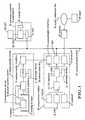
- FIG. 1is a view showing a hardware configuration of the embodiment of the present invention.
- the measurement module 1detects the heating, temperature and physical quantity of the sample 2 according to a designation from the measurement station 10 , and transmits the data to the measurement station 10 .
- the measurement module 1functions with the measurement control software processed at the central processing unit 7 and the storage device 8 installed in the measurement module 1 (the measurement control software operates as a task at the central processing unit 7 and the storage device 8 installed in the measurement module 1 and is hereinafter referred to as a measurement control task).
- the measurement station 10controls a plurality of measurement modules 1 , receives data from the measurement module 1 , and executes thermal analysis.
- the measurement station 10functions with the measurement control software processed at the central processing unit 15 and the storage device 16 installed in the measurement station 10 (the system control software activates as a task at the central processing unit 15 and the storage device 16 installed in the measurement station 10 , hereinafter referred to as a system control task).
- the temperature sensor 4evaluates the temperature of or in the vicinity of sample 2 .
- the physical quantity sensor 5detects, for example, the heat flow to the sample 2 with DSC, the change of the weight of the sample 2 with TG, or the change of shape of the sample 2 with TMA.
- the heating furnace 3 , the temperature sensor 4 , and the physical quantity sensor 5are connected to the 10 interface 6 installed in the measurement module 1 , and the central processing unit 7 is installed in the measurement module 1 .
- Temperature control of the heating furnace 3is executed by the central processing unit 7 installed in the measurement module 1 , which is connected to the heating furnace 3 via the I/O interface 6 installed in the measurement module 1 .
- the central processing unit 7 installed in the measurement module 1is connected to the measurement station 10 via the communication interface 9 installed in the measurement module unit 1 .
- the measurement station 10monitors user interfaces relating to measurements, control designations to a plurality of measuring modules, and events for data accumulation and measurement control tasks and system control tasks using a so-called personal computer or workstation.
- the measurement station 10performs the functions of a general operating system, such as Windows, Windows-NT, UNIX, etc., system control software and event monitoring software.
- the event monitoring softwarehas the functions of event monitoring, message control, and setting transmission information.(The function of the event monitoring software operates as a task at the central processing unit 15 and the storage device 16 installed in the measurement station 10 . This is referred to hereinafter as an event monitoring task, message control task, and transmission information setting task).
- the central processing unit 15 installed in the measurement station 10is connected to the plurality of measurement module units 1 via the communication interface 19 and the transmission line 20 installed in measurement station 10 .
- Any general communication linesuch as RS-232C, GP-IB, or SCSI can be adopted as the transmission line 20 .
- Control information related to the operation, error information of the software/hardware, and measured signals, etc.are exchanged between the measurement control task and the system control task via the transmission line 20 .
- the event monitoring taskmonitors the information being exchanged via the transmission line 20 periodically with the timer according to the algorithm described in FIG. 2, and detects arbitrary information preselected by the user as events, such as a signal notifying that measurement has reached a certain preset value, the completion of the measurement, the occurrence of an error, or the suspension of a task, etc.
- the measurement control task and the system control taskactivate independently from each other, so that monitoring can be executed regardless of the influence of a failure occurring for either one of the tasks.
- the eventwill be transmitted to the message control task (Any means such as DDE, IPC, and COM, etc. can be adopted as the means for communication between tasks).
- the transmission information setting taskhas functions to set the destination to transmit the message to and the event to monitor.
- a GUIis provided, and a user can arbitrarily select the destination to transmit the message to and an event to monitor with the mouse 11 , CRT 12 , and keyboard 13 installed in the monitoring station 10 (an algorithm for a transmission information setting task is shown in FIG. 3 ).
- the personal computer or the workstation 22 connected to the communication media 21 , or a pager 29 connected via the public telephone line 28can be selected as a message destination.
- the usercan select whether to transmit only to a specific computer or to broadcast to every computer connected to the network.
- the IP address of the destination computeris designated when transmitting to a specific computer and an IP address decided in advance for broadcast communication is designated for broadcast communication.
- the telephone number of the pager 29is designated.
- the messagecan be transmitted to a plurality of telephone numbers at the same time.
- a measurement control taskhas been suspended.
- the signalhas reached the preset value.
- the temperature of the heating furnacehas reached the preset value.
- the message transmission information as set aboveis stored in the storage device 16 installed in the measurement station 10 .
- the message control taskcreates a message packet consisting of the message and the destination to transmit the message to, that correspond to the event transmitted from the event monitoring task according to the message transmission information stored in the storage device 16 installed in the measurement station 10 , according to TCP/IP protocol (FIG. 4 shows the algorithm of the message control task).
- the created message packetwill be transmitted to the communication media 21 via the network interface card (hereafter referred to as NIC) 25 .
- NICnetwork interface card
- Any dedicated networksuch as Ethernet, FDDI, or Token Ring can be adopted as the communication media 21 .
- the messageWhen transmitting a message to the pager 29 , the message is transmitted to the serial port 18 to which the modem 27 is connected.
- the modem 27is connected to the public telephone line 28 , and transmits the message packet to the pager 29 via the public telephone line 28 .
- the technology for transmitting a message to the pager 29 via the public telephone line 28 and displaying the messageis a well known technology.
- the so-called personal computer or workstation 22is employed as the means for receiving message packets flowing in the communication media 21 such as local area network.
- the personal computerfunctions as a general operating system, such as Windows, Windows-NT, UNIX, etc., and as message receiving software (the message receiving software which operates on the personal computer or the workstation 22 will be referred as the message receiving task hereafter).
- the message receiving taskhas a function for receiving message packets flowing among the communication media 21 and the function of GUI to display the message on CRT 25 .
- the message receiving taskalways resides in the memory installed in the personal computer or the workstation 22 , and monitors the message packets flowing in the communication media 21 via the NIC 25 installed on the personal computer or the workstation 22 according to the algorithm shown in FIG. 5 .
- the destination of the transmitted messageis itself, it receives the message packet and notifies users of events that have occurred within the apparatus by retrieving the message from the message packet for displaying on the CRT 26 utilizing the GUI.
- eventsare monitored independently from the system control, and messages are transmitted to a computer or a pager at a remote location via the communication media, so that users are notified of the condition of the apparatus without paying special attention to it, in real time at any location;
Landscapes
- Chemical & Material Sciences (AREA)
- Engineering & Computer Science (AREA)
- Chemical Kinetics & Catalysis (AREA)
- Combustion & Propulsion (AREA)
- Physics & Mathematics (AREA)
- Health & Medical Sciences (AREA)
- Life Sciences & Earth Sciences (AREA)
- Analytical Chemistry (AREA)
- Biochemistry (AREA)
- General Health & Medical Sciences (AREA)
- General Physics & Mathematics (AREA)
- Immunology (AREA)
- Pathology (AREA)
- Investigating Or Analyzing Materials Using Thermal Means (AREA)
- Selective Calling Equipment (AREA)
- Mobile Radio Communication Systems (AREA)
- Telephonic Communication Services (AREA)
- Arrangements For Transmission Of Measured Signals (AREA)
Abstract
Description
The present invention relates to apparatus for thermal analysis.
Thermal analysis is a way of measuring physical changes of samples while changing the temperature, for temperatures in a range of from below-freezing temperature to 1500° C. Temperatures are measured by scanning a temperature range to be measured by raising temperature at an appropriate rate (in units of ° C./min). The length of time a measurement is made for is decided according to the rate of rising and the temperature range. The measuring time is usually somewhere around ten minutes to an hour, although a couple of hours to several days may be required for long measurements. As it is not necessary to operate the apparatus during measurements, in most cases, users merely keep on monitoring the apparatus while measurements are being taken. Therefore, cases where users carry out other work at a different location remote from the laboratory where the apparatus is installed are common.
In the situation described above, when some kind of trouble occurs that causes the measurements to be suspended, users are required to solve the problem and perform the measurements again.
However, as users are often located in a place far from the apparatus, they sometimes may not be aware that a problem has occurred. As the user may therefore neglect the apparatus without noticing that measurements have been interrupted, this may mean that an unnecessarily large amount of time may pass before measurements are restarted. The occurrence of problems rendering the apparatus uncontrollable also causes time to be wasted while carrying out measurements. Moreover, when a sample to be measured exhibits a fusion reaction, cases where proceeding with measurements beyond a certain preset value may ruin the sensor as the melted sample adheres onto it are common.
To enable more effective measurement, in the case of the occurrence of certain events such as, for example, the arrival of a signal notifying that a certain preset value is reached, the completion of a measurement, or an event where trouble has occurred within the apparatus, etc., it is preferable for the user to be notified of this situation in real time, wherever the apparatus may be.
Related technology for monitoring apparatus located at a remote location exist, such as, (1) monitoring measuring conditions via a network (Japanese Patent Laid-open Publication No. Hei. 9-325024), (2) suspend the operation of apparatus upon the occurrence of errors posing risks (Japanese Patent Laid-open Publication No. Hei. 5-19880), (3) manage the apparatus by utilizing E-mail (Japanese Patent Laid-open Publication No. Hen. 9-32950),
However, the following problems exist with this related technology.
The means for monitoring the measuring conditions via a network as disclosed in (1) above requires a user to keep observing the conditions at the place the monitor is installed while operating the monitor periodically. However, this means is not effective when a user is not on location, or forgets to observe the conditions.
The means for suspending the operation of apparatus upon the occurrence of an error posing risk as disclosed in (2) above can avoid risk for the time being, but the user will not be notified of the suspension at real time.
When the system itself halts as the result of the trouble occurring at the system control unit, neither (1) nor (2) disclosed above can detect the trouble.
With (1) or (2), the apparatus is monitored only by the user executing the measurements, and a number of people therefore cannot be aware of the emergency.
The means to monitor the apparatus using e-mail as disclosed in (3) above includes a similar problem to (1) above. Moreover, a time lag exists in order to retrieve e-mail from a mail server and users therefore cannot be notified in real time.
In order to resolve the aforementioned problems, the present invention sets out to provide an apparatus for thermal analysis with a monitoring unit installed separately from the system control unit so that an event occurring within the apparatus can be detected regardless of system operation conditions in real time and regardless of the location of the users, and the detected content can be notified to one or a plurality of users by transmitting a message.
The present invention was developed to resolve the aforementioned problems, and the main element of the configuration comprises a heating furnace, a temperature sensor, a physical quantity sensor, control measurement means, system control means, a storage device, an input output (I/O) unit, event monitoring means, event control means, information setting transmission means, message transmission means, message receiving means, user interface means, and a communication medium.
FIG. 1 is a drawing showing a hardware configuration of an embodiment of the present invention
FIG. 2 is an algorithm of a task for event monitoring of an embodiment of the present invention
FIG. 3 is an algorithm for a transmission information setting task of an embodiment of the present invention.
FIG. 4 is an algorithm of a message control task of an embodiment of the present invention.
FIG. 5 is an algorithm for message receiving of an embodiment of the present invention.
The following description is now given of an embodiment of the present invention based on the appended drawings.
FIG. 1 is a view showing a hardware configuration of the embodiment of the present invention.
Themeasurement module 1 detects the heating, temperature and physical quantity of thesample 2 according to a designation from themeasurement station 10, and transmits the data to the measurement station10.Themeasurement module 1 functions with the measurement control software processed at thecentral processing unit 7 and thestorage device 8 installed in the measurement module1 (the measurement control software operates as a task at thecentral processing unit 7 and thestorage device 8 installed in themeasurement module 1 and is hereinafter referred to as a measurement control task).
Themeasurement station 10 controls a plurality ofmeasurement modules 1, receives data from themeasurement module 1, and executes thermal analysis. Themeasurement station 10 functions with the measurement control software processed at thecentral processing unit 15 and thestorage device 16 installed in the measurement station10 (the system control software activates as a task at thecentral processing unit 15 and thestorage device 16 installed in themeasurement station 10, hereinafter referred to as a system control task).
Users of the apparatus for the thermal analysis place thesample 2 into theheating furnace 3 of themeasurement module 1. The change of temperature of thesample 2 is then detected with thetemperature sensor 4, and the change of physical quantity of thesample 2 is detected with thephysical quantity sensor 5. Thetemperature sensor 4 evaluates the temperature of or in the vicinity ofsample 2. Thephysical quantity sensor 5 detects, for example, the heat flow to thesample 2 with DSC, the change of the weight of thesample 2 with TG, or the change of shape of thesample 2 with TMA. Theheating furnace 3, thetemperature sensor 4, and thephysical quantity sensor 5 are connected to the10interface 6 installed in themeasurement module 1, and thecentral processing unit 7 is installed in themeasurement module 1. Temperature control of theheating furnace 3 is executed by thecentral processing unit 7 installed in themeasurement module 1, which is connected to theheating furnace 3 via the I/O interface 6 installed in themeasurement module 1. Thecentral processing unit 7 installed in themeasurement module 1 is connected to themeasurement station 10 via thecommunication interface 9 installed in themeasurement module unit 1.
Themeasurement station 10 monitors user interfaces relating to measurements, control designations to a plurality of measuring modules, and events for data accumulation and measurement control tasks and system control tasks using a so-called personal computer or workstation. Themeasurement station 10 performs the functions of a general operating system, such as Windows, Windows-NT, UNIX, etc., system control software and event monitoring software. The event monitoring software has the functions of event monitoring, message control, and setting transmission information.(The function of the event monitoring software operates as a task at thecentral processing unit 15 and thestorage device 16 installed in themeasurement station 10. This is referred to hereinafter as an event monitoring task, message control task, and transmission information setting task).
Thecentral processing unit 15 installed in themeasurement station 10 is connected to the plurality ofmeasurement module units 1 via thecommunication interface 19 and thetransmission line 20 installed inmeasurement station 10 . Any general communication line such as RS-232C, GP-IB, or SCSI can be adopted as thetransmission line 20.
Control information related to the operation, error information of the software/hardware, and measured signals, etc. are exchanged between the measurement control task and the system control task via thetransmission line 20. The event monitoring task monitors the information being exchanged via thetransmission line 20 periodically with the timer according to the algorithm described in FIG. 2, and detects arbitrary information preselected by the user as events, such as a signal notifying that measurement has reached a certain preset value, the completion of the measurement, the occurrence of an error, or the suspension of a task, etc. The measurement control task and the system control task activate independently from each other, so that monitoring can be executed regardless of the influence of a failure occurring for either one of the tasks. When an event is detected, the event will be transmitted to the message control task (Any means such as DDE, IPC, and COM, etc. can be adopted as the means for communication between tasks).
The transmission information setting task has functions to set the destination to transmit the message to and the event to monitor. A GUI is provided, and a user can arbitrarily select the destination to transmit the message to and an event to monitor with the mouse11,CRT 12, andkeyboard 13 installed in the monitoring station10 (an algorithm for a transmission information setting task is shown in FIG.3).
The personal computer or theworkstation 22 connected to thecommunication media 21, or apager 29 connected via thepublic telephone line 28 can be selected as a message destination.
When transmitting a message to the personal computer or theworkstation 22 connected to thecommunication media 21 such as the local area network, the user can select whether to transmit only to a specific computer or to broadcast to every computer connected to the network. The IP address of the destination computer is designated when transmitting to a specific computer and an IP address decided in advance for broadcast communication is designated for broadcast communication.
When a message is transmitted to thepager 29 via thepubic telephone line 28, the telephone number of thepager 29 is designated. When a message is transmitted to thepager 29, the message can be transmitted to a plurality of telephone numbers at the same time.
The options of the event to monitor are;
1 step of the temperature program completed.
Measurement completed.
A software error occurred at a measurement module.
A hardware error occurred at a measurement module.
A measurement control task has been suspended.
A software error occurred at a measurement station.
A system control task has been suspended. etc. related to the completion of the process and trouble report. In addition to those,
The signal has reached the preset value.
The temperature of the heating furnace has reached the preset value.
and signals during measurements and the condition of the temperature of the heating furnace are available as events. Those options are provided to meet the frequent needs in the thermal analysis to understand the condition of a measurement at any time demanded.
The message transmission information as set above is stored in thestorage device 16 installed in themeasurement station 10.
The message control task creates a message packet consisting of the message and the destination to transmit the message to, that correspond to the event transmitted from the event monitoring task according to the message transmission information stored in thestorage device 16 installed in themeasurement station 10, according to TCP/IP protocol (FIG. 4 shows the algorithm of the message control task).
To transmit a message to the personal computer orworkstation 22 connected to thecommunication media 21 such as local area network, the created message packet will be transmitted to thecommunication media 21 via the network interface card (hereafter referred to as NIC)25.Any dedicated network such as Ethernet, FDDI, or Token Ring can be adopted as thecommunication media 21.
When transmitting a message to thepager 29, the message is transmitted to theserial port 18 to which themodem 27 is connected. Themodem 27 is connected to thepublic telephone line 28, and transmits the message packet to thepager 29 via the public telephone line28.The technology for transmitting a message to thepager 29 via thepublic telephone line 28 and displaying the message is a well known technology.
The so-called personal computer orworkstation 22 is employed as the means for receiving message packets flowing in thecommunication media 21 such as local area network. The personal computer functions as a general operating system, such as Windows, Windows-NT, UNIX, etc., and as message receiving software (the message receiving software which operates on the personal computer or theworkstation 22 will be referred as the message receiving task hereafter). The message receiving task has a function for receiving message packets flowing among thecommunication media 21 and the function of GUI to display the message onCRT 25. The message receiving task always resides in the memory installed in the personal computer or theworkstation 22, and monitors the message packets flowing in thecommunication media 21 via theNIC 25 installed on the personal computer or theworkstation 22 according to the algorithm shown in FIG.5. When the destination of the transmitted message is itself, it receives the message packet and notifies users of events that have occurred within the apparatus by retrieving the message from the message packet for displaying on theCRT 26 utilizing the GUI.
As described above, in the present invention, events are monitored independently from the system control, and messages are transmitted to a computer or a pager at a remote location via the communication media, so that users are notified of the condition of the apparatus without paying special attention to it, in real time at any location;
so that users can operate the apparatus more effectively and more safely.
Claims (14)
1. An apparatus for thermal analysis comprising:
heating means for heating a sample;
a temperature sensor for detecting the temperature of, or in the vicinity of, the sample and outputting a corresponding signal;
a physical quantity sensor for detecting a changing physical quantity of the sample in accordance with changes in temperature;
one or more measurement control means for controlling the heating means and transmitting signals detected by the temperature sensor and the physical quantity sensor to a system side via a transmission line;
system control means connected by the transmission line to the one or more measurement control means for controlling the measurement control means, receiving signals detected by the measurement control means, and executing thermal analysis;
a storage device for storing signals detected by the measurement control means and commands for processing by the system control means;
an input/output unit for outputting results of thermal analysis obtained by the system control means from commands input by a user;
event monitoring means operating independently of the measurement control means and the system control means for periodically monitoring events occurring at the measurement control means and the system control means;
message control means for receiving a signal notifying of the occurrence of an event from the event monitoring means, assembling a message packet including a message and a destination to which the message is to be transmitted to according to the event, and executing a command to transmit the message packet;
transmission information setting means for setting information relating to message transmissions utilized by the message control means;
message transmission means for receiving a message packet from the message control means, and transmitting the message packet to a communication media;
message receiving means for retrieving message packets flowing in the communication media; and
user interface means for displaying a message included in the retrieved message packet.
2. An apparatus for thermal analysis according toclaim 1 ; wherein the transmission information setting means has means for permitting user selection of events to be monitored and destinations to which messages are to be transmitted.
3. An apparatus for thermal analysis according toclaim 1 ; wherein the message transmission means includes means for transmitting a message to one or a plurality of the message receiving means connected to the communication media.
4. An apparatus for thermal analysis according toclaim 1 ; wherein the message transmission means includes means for broadcasting a message to every message receiving means connected to the communication media at the same time.
5. An apparatus for thermal analysis according toclaim 1 ; wherein the message control means includes means for creating messages receivable by a pager, and for transmitting messages to a pager via a public telephone line.
6. An apparatus for thermal analysis according toclaim 1 ; wherein the event monitoring means operate independently from the system control means and the measurement control means so that suspension of the functions of the system control means and the measurement control means can be detected in real time.
7. An apparatus comprising;
a heating furnace for heating a sample;
a temperature sensor for detecting the temperature of, or in the vicinity of, the sample;
a physical quantity sensor for detecting a changing physical quantity of the sample in accordance with change in temperature;
one or more measurement control tasks for controlling the heating furnace and transmitting signals detected by the temperature sensor and the physical quantity sensor to a system side via a transmission line;
a system control task connected to more than one measurement control task by the transmission line for controlling the one or more measurement control tasks, receiving signals detected by the measurement control tasks, receiving signals detected by the measurement control tasks, and executing thermal analysis;
a storage device for storing signals detected by the measurement control tasks and commands for processing by the system control task;
an input/output unit for outputting results of thermal analysis obtained by the system control means from commands input by a user;
an event monitoring task independent of the measurement control tasks and the system control task for periodically monitoring events occurring within the measurement control task and the system control task;
a message control task for receiving a signal notifying of an occurrence of an event from the event monitoring task, assembling a message packet including a message and a destination to which the message is to be transmitted to in correspondence with the event, and executing a command to transmit the message packet;
a transmission information setting task for setting information related to message transmission utilized in the message control task;
message transmission means for receiving a message packet from the message control task, and transmitting the message packet to the communication media;
message receiving means for retrieving a message packet flowing at the communication media;
and user interface means for displaying a message included in the retrieved message packet.
8. A thermal analyzer comprising: a plurality of measurement units each for heating a sample to perform thermal analysis thereof; a system control unit for controlling the plurality of measurement units and being connected to the measurement units via a transmission line; an event monitoring unit operating independently of the measurement units and the system control unit for periodically monitoring for specified events occurring at the measurement units and the system control unit; and a message transmission unit for receiving notification of the occurrence of a specified event from the event monitoring unit and transmitting a message to a remote user over a communication medium.
9. A thermal analyzer according toclaim 8 ; wherein the measurement units comprise a furnace for heating a sample, a temperature sensor for detecting the temperature of or in the vicinity of the sample and outputting a corresponding signal, a physical quantity sensor for detecting a changing physical quantity of the sample in accordance with changes in temperature, and measurement control means for controlling the furnace and transmitting signals detected by the temperature sensor and the physical quantity sensor to the system control unit via the transmission line.
10. A thermal analyzer according toclaim 9 ; wherein the system control unit receives signals detected by the measurement control means and executes thermal analysis.
11. A thermal analyzer according toclaim 10 ; further comprising a storage unit for storing signals detected by the measurement control unit and commands for processing by the system control unit.
12. A thermal analyzer according toclaim 8 ; further comprising an input/output unit for outputting results of thermal analysis obtained by the system control unit based on commands input by a user and received over the communication medium.
13. A thermal analyzer according toclaim 8 ; wherein the message transmission unit comprises message control means for receiving a signal notifying of the occurrence of a specified event from the event monitoring unit, assembling a message packet including a message and a destination to which the message is to be transmitted to according to the event, and executing a command to transmit the message packet; transmission information setting means for setting information relating to message transmissions utilized by the message control means; and message transmission means for receiving a message packet from the message control means, and transmitting the message packet to the user over the communication media.
14. A thermal analyzer according toclaim 13 ; further comprising user interface means for displaying a message included in the retrieved message packet.
Applications Claiming Priority (2)
| Application Number | Priority Date | Filing Date | Title |
|---|---|---|---|
| JP11-361703 | 1999-12-20 | ||
| JP36170399AJP4083360B2 (en) | 1999-12-20 | 1999-12-20 | Thermal analyzer |
Publications (2)
| Publication Number | Publication Date |
|---|---|
| US20010004730A1 US20010004730A1 (en) | 2001-06-21 |
| US6529848B2true US6529848B2 (en) | 2003-03-04 |
Family
ID=18474601
Family Applications (1)
| Application Number | Title | Priority Date | Filing Date |
|---|---|---|---|
| US09/734,268Expired - LifetimeUS6529848B2 (en) | 1999-12-20 | 2000-12-11 | Thermal analysis apparatus |
Country Status (3)
| Country | Link |
|---|---|
| US (1) | US6529848B2 (en) |
| EP (1) | EP1111376A3 (en) |
| JP (1) | JP4083360B2 (en) |
Cited By (12)
| Publication number | Priority date | Publication date | Assignee | Title |
|---|---|---|---|---|
| US20030200349A1 (en)* | 2002-04-17 | 2003-10-23 | Hansen James R. | XML scripting of soap commands |
| US6757714B1 (en)* | 2000-07-28 | 2004-06-29 | Axeda Systems Operating Company, Inc. | Reporting the state of an apparatus to a remote computer |
| US7117239B1 (en) | 2000-07-28 | 2006-10-03 | Axeda Corporation | Reporting the state of an apparatus to a remote computer |
| US7149792B1 (en) | 2000-11-20 | 2006-12-12 | Axeda Corporation | Device registration mechanism |
| US7185014B1 (en) | 2000-09-22 | 2007-02-27 | Axeda Corporation | Retrieving data from a server |
| US20080082657A1 (en)* | 2006-10-03 | 2008-04-03 | Questra Corporation | A System and Method for Dynamically Grouping Devices Based on Present Device Conditions |
| US20080154957A1 (en)* | 2006-12-26 | 2008-06-26 | Questra Corporation | Managing configurations of distributed devices |
| US7966418B2 (en) | 2003-02-21 | 2011-06-21 | Axeda Corporation | Establishing a virtual tunnel between two computer programs |
| US8108543B2 (en) | 2000-09-22 | 2012-01-31 | Axeda Corporation | Retrieving data from a server |
| US8406119B2 (en) | 2001-12-20 | 2013-03-26 | Axeda Acquisition Corporation | Adaptive device-initiated polling |
| US8478861B2 (en) | 2007-07-06 | 2013-07-02 | Axeda Acquisition Corp. | Managing distributed devices with limited connectivity |
| US9319352B1 (en) | 2005-07-22 | 2016-04-19 | Marvell International Ltd. | Efficient message switching in a switching apparatus |
Families Citing this family (6)
| Publication number | Priority date | Publication date | Assignee | Title |
|---|---|---|---|---|
| US6839613B2 (en)* | 2001-07-17 | 2005-01-04 | General Electric Company | Remote tuning for gas turbines |
| AU2003254034A1 (en) | 2002-07-18 | 2004-02-09 | Pitney Bowes Inc. | Closed loop postage metering system |
| CN102541003A (en)* | 2011-12-27 | 2012-07-04 | 成都众询科技有限公司 | Wireless communication thermal analysis monitoring system |
| US10713877B2 (en)* | 2014-08-22 | 2020-07-14 | Illycaffe' S.P.A. Con Unico Socio | System and method to obtain and optimize mixtures for preparing beverages |
| CN106338203B (en)* | 2016-08-31 | 2019-03-08 | 宝武集团环境资源科技有限公司 | Visual field and temperature real-time monitoring system and control method in a kind of rotary hearth furnace |
| CN110686805B (en)* | 2019-10-17 | 2020-11-24 | 西安建筑科技大学 | A method and circuit for calibrating secondary reheat steam temperature signal in thermal power plant |
Citations (4)
| Publication number | Priority date | Publication date | Assignee | Title |
|---|---|---|---|---|
| US5568535A (en) | 1992-06-01 | 1996-10-22 | Trackmobile, Inc. | Alarm system for enclosed area |
| US5729197A (en) | 1996-02-22 | 1998-03-17 | Ultra Communications Corporation | Automatic, self-triggering alarm processing system and method |
| EP0920210A1 (en) | 1997-11-21 | 1999-06-02 | Kazuya Deguchi | Remote monitoring and security system and method |
| EP0959347A1 (en) | 1997-11-26 | 1999-11-24 | Seiko Instruments Inc. | Thermal analyzer |
Family Cites Families (1)
| Publication number | Priority date | Publication date | Assignee | Title |
|---|---|---|---|---|
| JPH10215494A (en)* | 1997-01-30 | 1998-08-11 | Shimadzu Corp | Remote monitoring system for automatic analyzer |
- 1999
- 1999-12-20JPJP36170399Apatent/JP4083360B2/ennot_activeExpired - Fee Related
- 2000
- 2000-12-11USUS09/734,268patent/US6529848B2/ennot_activeExpired - Lifetime
- 2000-12-13EPEP00311137Apatent/EP1111376A3/ennot_activeWithdrawn
Patent Citations (4)
| Publication number | Priority date | Publication date | Assignee | Title |
|---|---|---|---|---|
| US5568535A (en) | 1992-06-01 | 1996-10-22 | Trackmobile, Inc. | Alarm system for enclosed area |
| US5729197A (en) | 1996-02-22 | 1998-03-17 | Ultra Communications Corporation | Automatic, self-triggering alarm processing system and method |
| EP0920210A1 (en) | 1997-11-21 | 1999-06-02 | Kazuya Deguchi | Remote monitoring and security system and method |
| EP0959347A1 (en) | 1997-11-26 | 1999-11-24 | Seiko Instruments Inc. | Thermal analyzer |
Cited By (36)
| Publication number | Priority date | Publication date | Assignee | Title |
|---|---|---|---|---|
| US8898294B2 (en) | 2000-07-28 | 2014-11-25 | Axeda Corporation | Reporting the state of an apparatus to a remote computer |
| US6757714B1 (en)* | 2000-07-28 | 2004-06-29 | Axeda Systems Operating Company, Inc. | Reporting the state of an apparatus to a remote computer |
| US7117239B1 (en) | 2000-07-28 | 2006-10-03 | Axeda Corporation | Reporting the state of an apparatus to a remote computer |
| US8055758B2 (en) | 2000-07-28 | 2011-11-08 | Axeda Corporation | Reporting the state of an apparatus to a remote computer |
| US7937370B2 (en) | 2000-09-22 | 2011-05-03 | Axeda Corporation | Retrieving data from a server |
| US7185014B1 (en) | 2000-09-22 | 2007-02-27 | Axeda Corporation | Retrieving data from a server |
| US20070198661A1 (en)* | 2000-09-22 | 2007-08-23 | Axeda Corporation | Retrieving data from a server |
| US8762497B2 (en) | 2000-09-22 | 2014-06-24 | Axeda Corporation | Retrieving data from a server |
| US8108543B2 (en) | 2000-09-22 | 2012-01-31 | Axeda Corporation | Retrieving data from a server |
| US10069937B2 (en) | 2000-09-22 | 2018-09-04 | Ptc Inc. | Retrieving data from a server |
| US7149792B1 (en) | 2000-11-20 | 2006-12-12 | Axeda Corporation | Device registration mechanism |
| US8406119B2 (en) | 2001-12-20 | 2013-03-26 | Axeda Acquisition Corporation | Adaptive device-initiated polling |
| US9674067B2 (en) | 2001-12-20 | 2017-06-06 | PTC, Inc. | Adaptive device-initiated polling |
| US9170902B2 (en) | 2001-12-20 | 2015-10-27 | Ptc Inc. | Adaptive device-initiated polling |
| US8060886B2 (en) | 2002-04-17 | 2011-11-15 | Axeda Corporation | XML scripting of SOAP commands |
| US9591065B2 (en) | 2002-04-17 | 2017-03-07 | Ptc Inc. | Scripting of SOAP commands |
| US8752074B2 (en) | 2002-04-17 | 2014-06-10 | Axeda Corporation | Scripting of soap commands |
| US10708346B2 (en) | 2002-04-17 | 2020-07-07 | Ptc Inc. | Scripting of soap commands |
| US20030200349A1 (en)* | 2002-04-17 | 2003-10-23 | Hansen James R. | XML scripting of soap commands |
| US7178149B2 (en) | 2002-04-17 | 2007-02-13 | Axeda Corporation | XML scripting of soap commands |
| US8291039B2 (en) | 2003-02-21 | 2012-10-16 | Axeda Corporation | Establishing a virtual tunnel between two computer programs |
| US7966418B2 (en) | 2003-02-21 | 2011-06-21 | Axeda Corporation | Establishing a virtual tunnel between two computer programs |
| US10069939B2 (en) | 2003-02-21 | 2018-09-04 | Ptc Inc. | Establishing a virtual tunnel between two computers |
| US9002980B2 (en) | 2003-02-21 | 2015-04-07 | Axeda Corporation | Establishing a virtual tunnel between two computer programs |
| US9319352B1 (en) | 2005-07-22 | 2016-04-19 | Marvell International Ltd. | Efficient message switching in a switching apparatus |
| US9491071B2 (en) | 2006-10-03 | 2016-11-08 | Ptc Inc. | System and method for dynamically grouping devices based on present device conditions |
| US8769095B2 (en) | 2006-10-03 | 2014-07-01 | Axeda Acquisition Corp. | System and method for dynamically grouping devices based on present device conditions |
| US8370479B2 (en) | 2006-10-03 | 2013-02-05 | Axeda Acquisition Corporation | System and method for dynamically grouping devices based on present device conditions |
| US10212055B2 (en) | 2006-10-03 | 2019-02-19 | Ptc Inc. | System and method for dynamically grouping devices based on present device conditions |
| US20080082657A1 (en)* | 2006-10-03 | 2008-04-03 | Questra Corporation | A System and Method for Dynamically Grouping Devices Based on Present Device Conditions |
| US8788632B2 (en) | 2006-12-26 | 2014-07-22 | Axeda Acquisition Corp. | Managing configurations of distributed devices |
| US9491049B2 (en) | 2006-12-26 | 2016-11-08 | Ptc Inc. | Managing configurations of distributed devices |
| US9712385B2 (en) | 2006-12-26 | 2017-07-18 | PTC, Inc. | Managing configurations of distributed devices |
| US8065397B2 (en) | 2006-12-26 | 2011-11-22 | Axeda Acquisition Corporation | Managing configurations of distributed devices |
| US20080154957A1 (en)* | 2006-12-26 | 2008-06-26 | Questra Corporation | Managing configurations of distributed devices |
| US8478861B2 (en) | 2007-07-06 | 2013-07-02 | Axeda Acquisition Corp. | Managing distributed devices with limited connectivity |
Also Published As
| Publication number | Publication date |
|---|---|
| JP4083360B2 (en) | 2008-04-30 |
| US20010004730A1 (en) | 2001-06-21 |
| JP2001174423A (en) | 2001-06-29 |
| EP1111376A2 (en) | 2001-06-27 |
| EP1111376A3 (en) | 2002-03-06 |
Similar Documents
| Publication | Publication Date | Title |
|---|---|---|
| US6529848B2 (en) | Thermal analysis apparatus | |
| US7058508B2 (en) | Automated building service broker | |
| EP1239434A2 (en) | System and method for remote management of equipment operating parameters | |
| US7227450B2 (en) | Internet facilitated fire alarm monitoring, control system and method | |
| JP4545145B2 (en) | Distribution of process plant notifications | |
| US20020198990A1 (en) | System and method for remotely monitoring and controlling devices | |
| US20070033087A1 (en) | Automated service broker | |
| US20030001737A1 (en) | Automatic alarm system | |
| WO2001080032A1 (en) | A system and method for managing computing devices within a data communications network from a remotely located console | |
| US20010056484A1 (en) | System, method and control unit for generating a message as e-mail via Internet and/or intranet | |
| US8635337B2 (en) | System and method of troubleshooting | |
| JP6776078B2 (en) | Freezer monitoring device, freezer monitoring system and freezer monitoring method | |
| JP4328672B2 (en) | Information processing apparatus and device | |
| Swan | The language of bacnet-objects, properties and services | |
| KR100697079B1 (en) | Central control system of multi-air conditioner and its error notification method | |
| JPH06175944A (en) | Network monitoring method | |
| JP2003248888A (en) | Fire alarm system | |
| JP2007116586A (en) | Facility supervisory system | |
| CN210639735U (en) | Alarm running state monitoring system | |
| EP2136323B1 (en) | Assignment of alarms | |
| CN100476665C (en) | Data Management Collection System | |
| JPH0630469A (en) | Remote monitoring system for multiple facilities | |
| JPH04332227A (en) | Failure information transmission destination control system | |
| EP4303844A1 (en) | Alarm system, control device, and detector | |
| JPH10247962A (en) | Computer communication monitoring system |
Legal Events
| Date | Code | Title | Description |
|---|---|---|---|
| AS | Assignment | Owner name:SEIKO INSTRUMENTS INC., JAPAN Free format text:ASSIGNMENT OF ASSIGNORS INTEREST;ASSIGNOR:SONE, YUUYA;REEL/FRAME:013648/0789 Effective date:20021224 | |
| STCF | Information on status: patent grant | Free format text:PATENTED CASE | |
| AS | Assignment | Owner name:SII NANOTECHNOLOGY INC., JAPAN Free format text:ASSIGNMENT OF ASSIGNORS INTEREST;ASSIGNOR:SEIKO INSTRUMENTS INC.;REEL/FRAME:015711/0053 Effective date:20050128 | |
| FPAY | Fee payment | Year of fee payment:4 | |
| FPAY | Fee payment | Year of fee payment:8 | |
| FEPP | Fee payment procedure | Free format text:PAYOR NUMBER ASSIGNED (ORIGINAL EVENT CODE: ASPN); ENTITY STATUS OF PATENT OWNER: LARGE ENTITY | |
| FPAY | Fee payment | Year of fee payment:12 | |
| AS | Assignment | Owner name:HITACHI HIGH-TECH SCIENCE CORPORATION, JAPAN Free format text:CHANGE OF NAME;ASSIGNOR:SII NANOTECHNOLOGY INC.;REEL/FRAME:033817/0078 Effective date:20130101 |