US6529839B1 - Energy coordination system - Google Patents
Energy coordination systemDownload PDFInfo
- Publication number
- US6529839B1 US6529839B1US09/086,122US8612298AUS6529839B1US 6529839 B1US6529839 B1US 6529839B1US 8612298 AUS8612298 AUS 8612298AUS 6529839 B1US6529839 B1US 6529839B1
- Authority
- US
- United States
- Prior art keywords
- energy
- schedule
- schedules
- user
- predetermined
- Prior art date
- Legal status (The legal status is an assumption and is not a legal conclusion. Google has not performed a legal analysis and makes no representation as to the accuracy of the status listed.)
- Expired - Lifetime
Links
- 238000004891communicationMethods0.000claimsabstractdescription36
- 238000005265energy consumptionMethods0.000claimsabstractdescription6
- 238000000034methodMethods0.000claimsdescription24
- 241001050985DiscoSpecies0.000claimsdescription21
- 230000005611electricityEffects0.000claimsdescription13
- 230000003466anti-cipated effectEffects0.000claimsdescription11
- 230000006870functionEffects0.000claimsdescription4
- 230000003247decreasing effectEffects0.000claimsdescription2
- 101100170539Drosophila melanogaster disco geneProteins0.000description20
- 238000013519translationMethods0.000description14
- 230000005540biological transmissionEffects0.000description9
- 238000012795verificationMethods0.000description8
- 238000012545processingMethods0.000description7
- 230000002093peripheral effectEffects0.000description6
- 230000002074deregulated effectEffects0.000description5
- 230000008569processEffects0.000description5
- 238000012790confirmationMethods0.000description4
- 238000005070samplingMethods0.000description4
- 230000008520organizationEffects0.000description3
- 230000008859changeEffects0.000description2
- 238000010586diagramMethods0.000description2
- 238000005259measurementMethods0.000description2
- VNWKTOKETHGBQD-UHFFFAOYSA-NmethaneChemical compoundCVNWKTOKETHGBQD-UHFFFAOYSA-N0.000description2
- 230000000712assemblyEffects0.000description1
- 238000000429assemblyMethods0.000description1
- 230000008901benefitEffects0.000description1
- 238000004590computer programMethods0.000description1
- 230000001276controlling effectEffects0.000description1
- 230000003831deregulationEffects0.000description1
- 230000000694effectsEffects0.000description1
- 238000012986modificationMethods0.000description1
- 230000004048modificationEffects0.000description1
- 239000003345natural gasSubstances0.000description1
- 239000003208petroleumSubstances0.000description1
Images


Classifications
- H—ELECTRICITY
- H02—GENERATION; CONVERSION OR DISTRIBUTION OF ELECTRIC POWER
- H02J—CIRCUIT ARRANGEMENTS OR SYSTEMS FOR SUPPLYING OR DISTRIBUTING ELECTRIC POWER; SYSTEMS FOR STORING ELECTRIC ENERGY
- H02J3/00—Circuit arrangements for AC mains or AC distribution networks
- H02J3/008—Circuit arrangements for AC mains or AC distribution networks involving trading of energy or energy transmission rights
- H—ELECTRICITY
- H02—GENERATION; CONVERSION OR DISTRIBUTION OF ELECTRIC POWER
- H02J—CIRCUIT ARRANGEMENTS OR SYSTEMS FOR SUPPLYING OR DISTRIBUTING ELECTRIC POWER; SYSTEMS FOR STORING ELECTRIC ENERGY
- H02J3/00—Circuit arrangements for AC mains or AC distribution networks
- H02J3/004—Generation forecast, e.g. methods or systems for forecasting future energy generation
- Y—GENERAL TAGGING OF NEW TECHNOLOGICAL DEVELOPMENTS; GENERAL TAGGING OF CROSS-SECTIONAL TECHNOLOGIES SPANNING OVER SEVERAL SECTIONS OF THE IPC; TECHNICAL SUBJECTS COVERED BY FORMER USPC CROSS-REFERENCE ART COLLECTIONS [XRACs] AND DIGESTS
- Y04—INFORMATION OR COMMUNICATION TECHNOLOGIES HAVING AN IMPACT ON OTHER TECHNOLOGY AREAS
- Y04S—SYSTEMS INTEGRATING TECHNOLOGIES RELATED TO POWER NETWORK OPERATION, COMMUNICATION OR INFORMATION TECHNOLOGIES FOR IMPROVING THE ELECTRICAL POWER GENERATION, TRANSMISSION, DISTRIBUTION, MANAGEMENT OR USAGE, i.e. SMART GRIDS
- Y04S10/00—Systems supporting electrical power generation, transmission or distribution
- Y04S10/50—Systems or methods supporting the power network operation or management, involving a certain degree of interaction with the load-side end user applications
- Y—GENERAL TAGGING OF NEW TECHNOLOGICAL DEVELOPMENTS; GENERAL TAGGING OF CROSS-SECTIONAL TECHNOLOGIES SPANNING OVER SEVERAL SECTIONS OF THE IPC; TECHNICAL SUBJECTS COVERED BY FORMER USPC CROSS-REFERENCE ART COLLECTIONS [XRACs] AND DIGESTS
- Y04—INFORMATION OR COMMUNICATION TECHNOLOGIES HAVING AN IMPACT ON OTHER TECHNOLOGY AREAS
- Y04S—SYSTEMS INTEGRATING TECHNOLOGIES RELATED TO POWER NETWORK OPERATION, COMMUNICATION OR INFORMATION TECHNOLOGIES FOR IMPROVING THE ELECTRICAL POWER GENERATION, TRANSMISSION, DISTRIBUTION, MANAGEMENT OR USAGE, i.e. SMART GRIDS
- Y04S50/00—Market activities related to the operation of systems integrating technologies related to power network operation or related to communication or information technologies
- Y04S50/10—Energy trading, including energy flowing from end-user application to grid
Definitions
- the present inventionis related to an energy coordination system, and more particularly, to an energy coordination system that facilitates a customer's ability to choose its energy provider.
- FIG. 1The traditional model for electric utilities is shown in FIG. 1 .
- an electric utilityserves energy users or customers 108 (i.e., load) with its own facilities 100 , which includes a generator 102 , a transmission network 104 , and a distribution network 106 .
- a transformer station 105is connected between the transmission network 104 and the distribution network 106 .
- a customer 108cannot choose between alternative sources of energy. The customer 108 must buy energy from the utility that operates in its geographic region.
- Control Areas 114 and 116are electrical systems bounded by interconnection (i.e., tie-line) metering 118 and telemetry.
- the load between adjacent Control Areas 114 and 116is balanced according to a predetermined schedule. If excess demand for electricity is generated in one Control Area 114 , it will receive electricity from adjacent Control Areas 116 , which disrupts the balance.
- Generators 120 and 122 in the Control Areas 114 and 116must then adjust their generation to return the balance to zero.
- the Control Area 116 that is providing the excess electricitythen bills the other Control Area 114 for expenses caused by the deviation.
- the present inventionis directed to a system for scheduling the provision of energy in an energy distribution network having a plurality of energy users receiving energy from at least one of a plurality of energy sources.
- the systemcomprises memory in communication with the input.
- the memoryis configured to store at least one schedule for each energy user.
- Each schedulesets forth the predicted energy usage over a predetermined period of time.
- a processoris in communication with the memory.
- the processoris configured to sum the schedules of a predetermined set of energy users thereby creating a net schedule.
- Another embodiment of the present inventionis directed to a system for allocating the deviation between an energy user's predicted energy usage and the energy user's actual energy usage.
- the systemcomprises means for receiving meter readings of actual energy consumption for the energy user.
- Memoryis in communication with the means for receiving meter readings.
- the memoryis configured to store a schedule of anticipated energy usage for a predetermined period and to store the energy users' meter readings.
- a processoris in communication with the memory. The processor is configured to calculate the difference between the schedule and the meter readings thereby forming a deviation between anticipated energy use and actual energy use for each energy user.
- Yet another embodiment of the present inventionis a method for scheduling the generation of energy in an energy distribution network having a plurality of energy users receiving energy from at least one of a plurality of energy sources.
- the methodcomprising the steps of: storing a schedule for each energy user, each schedule setting forth the predicted energy usage for that energy user over a predetermined period of time; and summing the schedules of a predetermined set of energy users thereby creating a net schedule.
- Another method that embodies the present inventionis for allocating the deviation between an energy user's predicted energy usage and the energy user's actual energy usage.
- This methodcomprising the steps of: receiving meter readings of actual energy consumption for the energy user; storing a schedule of anticipated energy usage for a predetermined period; storing the energy users' meter readings; and calculating the difference between the schedule and the meter readings thereby forming a deviation between anticipated energy use and actual energy use for each energy user.
- FIG. 1illustrates the traditional model for a regional electric utility
- FIG. 2illustrates the traditional model of a power grid that has the regional electric utilities organized into Control Areas
- FIG. 3illustrates one possible model for a power system that utilizes a computer system embodying the present invention
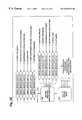
- FIG. 4illustrates organization of components in one possible model of a deregulated utility industry that utilizes the power system shown in FIG. 3;
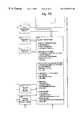
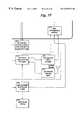
- FIG. 5is a functional block diagram illustrating one possible embodiment of the computer system shown in FIG. 3;
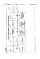
- FIG. 6is a block diagram of one possible embodiment of the hardware for implementing the computer system shown in FIGS. 3 and 5 .
- the present inventionis directed to a system for coordinating various components and entities in a deregulated energy distribution system.
- Various embodiments of the present inventioncan be utilized with the generation and/or distribution of many different types of energy, including electricity, natural gas, and petroleum.
- the present inventioncan be implemented in many different models for the utility industry and is not limited to the particular module that is described herein.
- the inventioncan be used in a system that does not include an independent system operator as described below.
- a system embodying the present inventiondetermines the deviation between each customer's scheduled energy usage and the customer's actual usage of energy. This deviation provides a basis for allocating the cost of deviation to the customers that are actually responsible for the deviation in a prorated amount. Thus, customers pay only for their energy usage and not for the excess usage of other customers.
- a system embodying the present inventionis directed to creating net usage schedules that are used to control the amount of energy output by various generators. Creating and using net usage schedules in this manner helps to maintain balance in the energy distribution system.
- An advantage of this systemis that it enables a customer to choose its desired source of energy. For example, a customer can choose to continue receiving energy from its traditional energy provider for the geographic area in which the customer is located. The customer can also choose to purchase energy from an alternative energy provider or directly from a generator. In yet another example, a A customer can choose to purchase energy from multiple and different sources depending on a variety of factors such as the time of day, the day of the week, or whether the customer's actual energy usage is exceeding its scheduled usage.
- FIG. 3illustrates one possible model of a power system 123 that utilizes the present invention.
- a plurality of generators 124 , 125 , and 126generate energy into a transmission network 128 .
- a distribution network 130receives energy from the transmission network and distributes the energy to the loads 132 , 134 , 136 , and 138 .
- a transformer station 131is positioned between the transmission network 128 and the distribution network 130 .
- the loads 132 , 134 , 136 , and 138can be any type of customer, or combinations of different types of customers, including residential, commercial, and industrial customers.
- meters 140 , 142 , 144 , and 146that measure the flow of energy between the distribution network 130 and the loads 132 , 134 , 136 , and 138 .
- meters 148 , 150 , 152that measure the flow of electricity between the generators 124 , 125 , and 126 and the transmission network 128 .
- a computer system 220is interfaced with, or electrically connected to, the meters 140 , 142 , 144 , 146 , 148 , 150 , and 152 .
- FIG. 4illustrates one possible structure of the electric utility industry in a deregulated environment in which a customer 1 - 7 can choose its own source of electricity.
- a customer 1 - 7can choose to keep receiving energy from its regional DISCO 219 , which is the traditional regional utility, or choose to switch to an alternative energy provider 242 .
- An Independent System Operator (ISO) 244is a regional organization that operates the transmission network 130 independently of its owners.
- the ISO 244can operate transmission networks owned by several different companies or a single transmission network. Analogously, the ISO 244 can encompass several Control Areas, a single Control Area, or combine several Control Area into a larger unitary Control Area.
- the ISO 244is responsible for the reliability of the networks within its system and have contracted with a generator 225 that will provide load-following services.
- the load-following generator 225 with whom the ISO is associatedis the default generator that provides excess electricity when demand exceeds the load scheduled for >the network.
- Another organizationsuch as an independent energy accountant (IEA) 154 provides a central control that coordinates all of the components for the ISO 244 . Accordingly, the IEA 154 operates the computer system 220 and provides account switching, short-interval scheduling, and deviation accounting.
- IVAindependent energy accountant
- the IEA 154communicates with the ISO 244 ; generators 156 and 158 ; the regional DISCO 219 ; energy providers 242 that receive load-following from the default generator 225 ; energy providers 242 that contract with alternative load following generators 223 ; customers, such as customer 6 , that choose to contract directly with a particular generator for either their main supply of energy 156 or 158 or their load following energy provider 223 ; and customers, such as customer 7 , that have short-interval metering.
- control or coordinationis provided by an entity other than the ISO 154 . Examples of other entities include an independent energy scheduling service or a distribution company.
- the computer system 220interfaces with energy meters 200 , after-the-fact interval meters 202 , short-interval meters 204 , and generator meters 206 .
- Energy meters 200do not have load-profile recorders and typically are used for residential customers.
- After-the-fact interval meters 202have built in load-profile recorders and typically have dial-up communications with an entity that has a meter translation system such as a DISCO.
- After-the-fact interval meters 202typically are used for commercial and light industrial customers.
- Short-interval meters 204record energy on a near real-time basis.
- Short-interval meters 204typically are used for large industrial customers.
- Generator meters 206track the output of generators on a near real-time basis.
- Meters operating on a near real-time basistake measurements at relatively short intervals, such as five minute intervals.
- the length of the intervalcan vary depending on a variety of factors such as the capabilities of the meter, the capacity of the communication system to which the meter is linked, and the number of customers. The shorter the interval between readings the closer that the system is to achieving true real-time measurement. In some possible configurations, therefore, near real-time is synonymous with real-time if the intervals are short enough.
- a meter translation system 210includes a communication interface 212 , a meter data translation and processing system 214 , a high precision time base 216 , and a customer load profile history database 218 .
- the communication interface 212provides an interface for after-the-fact meters 202 .
- the communication interface 212dials up and polls the individual after-the-fact meters 202 that are installed at various customers. Each after-the-fact meter 202 generates a metered load profile, which is a profile of actual usage that charts actual use over a period of time. That period of time can have various intervals such as 1 day, 1 week, or 1 month.
- a metered load profilewhich is a profile of actual usage that charts actual use over a period of time. That period of time can have various intervals such as 1 day, 1 week, or 1 month.
- after-the-fact meters 202download into the meter data translation and processing unit 214 both their metered load profile and the meter reading for the end of the profiled interval.
- the meter profiles as well as the actual meter readings at the start and stop of the profiled intervalare stored in the customer load profile history database 218 .
- the time base 216receives time from a precision atomic clock source. This high precision time is used to synchronize the clock in each of the after-the-fact meters 202 .
- the standard energy meters 200are typically read by a meter reader and input into a hand-held meter reading microcomputer 201 .
- This hand-held meter reading microcomputer 201is interfaced with the DISCO's electronic meter reading system 208 . If the customer has not elected to switch to an alternative energy provider, the meter readings are input into the DISCO's billing system 203 and the DISCO 219 will generate billing for that customer in a manner that is known in the art. If the customer has elected to switch energy providers, the data from the DISCO's meter reading system 208 is input into the meter data and translation and processing 214 of the meter translation system 210 . In an alternative embodiment, the meter readings are also stored in the customer load profile history database 218 .
- the DISCO meter reading system 208communicates meter readings from switched customers directly to the first input interface 205 of the computer system 220 , which is described in more detail below, rather than communicating the meter readings to the meter translation system 210 .
- the computer system 220includes a deviation accounting processor 222 ; a schedule processor 224 ; first, second, and third input interfaces 205 , 226 , and 228 ; first and second output interfaces 215 and 230 ; a real-time database 232 ; a relational database 234 ; a reconciliation processor 211 ; a customer verification processor 209 ; and a prescheduling processor 213 .
- the second input interface 226 , the schedule processor 224 , the real-time database 232 , and the second output interface 230form a real-time processor 231 that enables the computer system 220 to quickly respond to changes in customer demand so that the generators can adjust the amount of energy that they generate and minimize any imbalances.
- the processors described hereincan be computer programs or portions of programs such as routines or objects.
- the relational database 234stores information relating to demographics, energy metered customers, after-the-fact interval metered customers, short-interval metered customers; generators, including load following suppliers; and energy providers.
- Demographic information that is stored in the relational databaseincludes data regarding generators, energy providers, and customers that have switched to an energy provider other than their geographic DISCO.
- Each of the generators, energy providers, and customersis represented by a flag, code, or character string.
- the relational database 234creates relationships between generators and energy providers that have energy supply contracts, customers and energy providers that have energy supply contracts, and customers and generators that have energy supply contracts.
- the relational databasealso contains information regarding the interval during which the generator or energy provider is scheduled to supply energy.
- Data stored in the relational database 234 regarding energy metered customers 200includes preschedules, temperature coefficients, adjusted schedules, actual monthly meter readings, reconciled schedules, and deviations.
- Data regarding after-the-fact interval metered customers 202includes preschedules, temperature coefficients, adjusted schedules, metered load profiles, and deviations.
- Data regarding short-interval metered customers 204includes preschedules, metered load profiles, and deviations.
- Data regarding the generators 206includes preschedules, adjusted schedules, metered generation profiles, and deviations.
- Data regarding the energy providers 242includes preschedules, temperature basis by zip code, the net of adjusted schedules and short-interval metering for the energy provider's customers, a net of reconciled and metered load profiles, and deviations.
- the temperature basisis the predicted temperature.
- the temperature coefficientis a factor that is added to the preschedule for every degree that the actual temperature differs from the temperature basis. It accounts for increased (or decreased) energy usage caused by climate control units such as air conditioners that result from unexpected temperature swings. There is a separate temperature coefficient for each customer. Additionally, the temperature coefficient is determined through statistical sampling based upon a customer's, or a sampling of similar customers', historic energy usage.
- the temperature basisis 60° and the actual temperature is 70°
- a customerhas a first temperature coefficient that is added to the preschedule 10 times, once for every degree that the actual temperature exceeds the temperature basis of 60°.
- the temperature basisis 80° and the actual temperature is 85°
- the same customerwill have a different temperature coefficient that is added to the scheduled energy usage 5 times, once for every degree that the actual temperature exceeds the temperature basis of 80°. Knowledge on how to compute these coefficients is well known in the art.
- the first input interface 205receives data from the meter data translation and processing system 214 and loads that information into the relational database 234 .
- This dataincludes the current metered load profiles for after-the-fact metered customers 202 and actual meter readings for energy metered customers 200 .
- a historical metered load profilewill be communicated from the customer load-profile database 218 to the first input interface 205 .
- the second input communication interface 226is a near real-time interface that polls the short-interval meters 204 that are installed at customers' facilities and generator meters 206 . The short-interval meter values, are then downloaded from the second input interface 226 to the near real-time database 232 .
- the second input interface 226also receives adjusted schedules from other ISOs and IEAs 217 . This information is used to schedule and maintain a balance between Control Areas and for billing purposes if there is an imbalance created between the Control Areas. The information also enables customers and energy providers from other Control Areas to purchase energy from a generator 206 in the Control Area of the computer system 220 .
- Each generatorhas a generator prescheduling processor 236 that generates a preschedule of electricity that it plans to generate for a predetermined period.
- each energy provider 242has a load prescheduling processor 238 that generates schedules or preschedules for each of its customers.
- Each prescheduleis created through statistical sampling based upon a customer's, or a sampling of similar customers', historic energy usage. Additionally, each preschedule corresponds to the energy that the energy provider 242 expects to provide to the customer for which the preschedule is created.
- the preschedulesare communicated to the second input interface 228 by means such as e-mail or other electronic communications, and are then stored in the relational database 234 .
- the preschedulecan cover any future period. In one possible embodiment, however, the preschedules cover a 24-hour period and are created one day in advance of the period that the schedule covers.
- the prescheduling processor 213retrieves all of the preschedules for a given energy provider from the relational database 234 .
- the preschedulesare then summed by Control Area 244 , energy provider 242 , and DISCO 219 to create net preschedules.
- the net preschedulesare stored in the relational database 234 and communicated to the ISO 244 , the DISCOs 219 , the energy providers 242 , and the load following generators 223 via the first output interface 215 .
- the schedule processor 224generates a net adjusted schedule for each of the energy providers 242 .
- the net adjusted scheduleis the schedule of the amount of electricity that customers of the energy provider 242 expect to use during a given period of time.
- the net adjusted scheduleincludes information for all of the energy provider's 242 customers, including short-interval metered customers 204 , after-the-fact metered customers, and energy metered customers 200 .
- the schedule processor 224retrieves the customer data and the preschedule for all of the energy provider's 242 customers, including the short-interval metered customers 204 , after-the-fact metered customers 202 , and energy metered customers 200 .
- the schedule processor 224also retrieves actual weather data from a weather service 240 and the corresponding temperature coefficients from the relational database 234 .
- An example of possible weather data that is retrieved from the weather serviceincludes the actual temperature by zip code.
- the scheduling processor 224then creates an adjusted schedule by adjusting the preschedules for after-the-fact interval metered customers 202 and energy metered customers 200 on an hourly basis using the temperature coefficient correspondence to the temperature basis and the most recent actual temperature that the computer system 220 has received.
- the schedule processor 224also compiles a metered load profile for each of the short-interval customers 206 .
- the metered load profiles of the short-interval metered customers 206 , the adjusted schedules for after-the-fact metered customers 204 , and the adjusted schedules for energy metered customers 200are summed to create the net adjusted schedule.
- This process of calculating the net adjusted scheduleis periodically performed for each of the generators, energy providers, Control Areas, DISCOs, and other IEAs.
- a new net adjusted scheduleis created every five minutes to provide a near real-time schedule so that generators can periodically adjust the amount of energy they are providing to minimize energy imbalance.
- a new net adjusted scheduleis calculated in intervals other than five minutes, depending on a variety of factors including communication between the computer system 200 and the peripheral systems as well as processing demands placed on the computer system 200 . The interval could be less than five minutes or considerably greater than five minutes.
- the scheduling processor 224also periodically creates an inter-IEA/Control Area schedule. This schedule is used to update information about the balance between Control Areas and inform any contracted generators in other Control Areas of the size of the load that they need to generate to serve customers in their host Control Area.
- the scheduling processor 224stores the weather information, preschedules, adjusted schedules, and short-interval metered load profiles in the real-time database 232 . Storing this information in the real-time database 232 enables the schedule processor 224 to quickly retrieve it for updating or adjusting the schedules.
- the schedule processor 224also stores the short-interval metered load profiles and the adjusted schedules in the relational database 234 to create a historical record of data.
- the net adjusted scheduleis output from the schedule processor 224 via the second output interface 230 to the energy providers 242 , the ISO 244 , the load following providers 223 , the DISCO 219 , and other IEAs and Control Areas 221 that might have a need for the adjusted schedule.
- the energy providers 242can use this information for a variety of purposes such as computing an alternate net adjusted generation schedule, keeping historical records, billing purposes, and accounting purposes.
- the alternate net adjusted scheduleis an alternate generation schedule that determines how much to adjust the energy being purchased from generators and load following generators as the deviations are determined.
- the alternate net adjusted scheduleis then communicated back to the real-time database 232 via the second input interface 226 .
- the scheduling processor 224uses this information to adjust the schedules of the appropriate generators and load following generators.
- the alternate net adjusted generation scheduleis also communicated directly from the energy providers 242 to the load following generators 223 .
- the load-following generatorscan use the alternate net adjusted generation schedule for billing and to quickly adjust their generation to match customer demand and maintain balance of the system.
- the ISOs 244use the net adjusted schedule as a measure of the amount of energy that must be available on the network at any given time.
- the ISO 244compares the net adjusted schedules with the net preschedules to assist in maintaining reliability. This comparison, for example, is used to determine how much energy the load-following generators must provide in order to meet customer demand and maintain a balanced power system. In another example, this comparison is used to adjust the output of load-following generators with whom customers have contracted 223 in order to minimize dependence on the ISO's default load-following generators 225 to meet demand and balance the power system.
- the second output interface 230also communicates in near real-time the net adjusted schedules to load-following generators 223 with whom particular energy providers have independently contracted. In this situation, the individual contracted load-following generator 223 will increase or decrease generation of energy to follow the energy provider's or customer's adjusted schedule.
- Inter-Control Area schedulesare communicated from the second output interface 230 to the other IEAs and Control Areas 221 , which use this information for generating their own load schedules.
- This informationpermits a customer or energy provider in one Control Area to contract with a generator in another Control Area.
- This informationis also used to schedule and maintain a balance between adjacent Control Areas and for billing purposes if the load between adjacent Control Areas becomes unbalanced.
- the net preschedules and adjusted schedules for all of the switched customers within each DISCOare transmitted to the DISCOs 219 .
- Each DISCOcan then use this information to calculate its own preschedule.
- the DISCO 219also receives each energy provider's net preschedule from the first output interface 215 .
- the reconciliation processor 211retrieves the adjusted schedule or schedules and actual monthly meter readings for every energy metered customer 200 from the relational database 234 .
- the reconciliation processor 211uses the actual monthly meter reading to scale the adjusted schedule for each customer and create a reconciled schedule.
- the amount of energy represented in the reconciled scheduleis substantially equivalent to the energy metered customer's actual usage.
- the total amount of energy represented in a customer's or energy user's reconciled schedulecorresponds to the customer's total monthly consumption of energy.
- the reconciled scheduleis stored in the relational database 234 .
- the deviation processor 222calculates the deviation between the adjusted schedule and the actual energy used for each customer and for each generator.
- the deviation processor 222retrieves information from the relational database 234 for each customer.
- the deviation processor 222retrieves the adjusted schedule and the reconciled schedule.
- the deviation processor 222then calculates the difference between the reconciled schedule and the adjusted schedule, which is the deviation.
- the deviation processor 222retrieves the adjusted schedule and the metered load and generation profiles from the relational database 234 .
- the deviation processor 222then calculates the difference between the metered load profile and the adjusted schedule, which is the deviation.
- the metered load profilebecomes the adjusted schedule, and there is not a deviation between the adjusted schedule and metered load profile for short interval metered customers.
- the deviations for the customerswill be divided based on negotiated contracts.
- the deviations for individual customersare communicated to each customer's energy provider 242 through the first output communication interface 215 and are stored in the relational database 234 .
- the net deviation for each energy provider and generatoris provided to the ISO 244 .
- the energy provider 242uses the deviation for each individual customer to allocate the deviation billing from the ISO 244 to the individual customers in an amount proportioned to the customer's individual deviation.
- the workstation 246is used to input demographic information for each customer into the relational database 234 .
- Demographic informationcan include personal information, the identity of the primary energy provider with whom the customer has contracted, and the identity of secondary energy providers with whom the customer has contracted.
- the customer verification processor 209prevents slamming of customers. Slamming occurs when an energy provider 242 switches a customer to its service without the customer's permission.
- the customer verification processor 209receives requests from the energy provider 242 for changes in the customer's chosen energy provider. This information can be communicated electronically or directly from the energy provider 242 to the customer verification processor 209 . Alternatively, this information can be sent to the IEA, and is then manually input to the verification processor 209 at the work station 246 .
- the verification processor 209Upon receiving a request to switch a customer, the verification processor 209 causes a confirmation request to be generated and sent to the customer 207 .
- the confirmation requestcan have many possible formats such as a mailing or a digital certificate.
- the verification processor 209will update the information in the relational database 234 that identifies the customer's 207 new energy provider 242 .
- the confirmationis also communicated to the customer's previous energy provider 242 notifying it that the customer switched to another energy provider 242 .
- the same process as described abovewill be used of a customer selects an additional energy provider. The change then takes effect after the next meter reading.
- the computer system 220has four servers 300 , 302 , 304 , and 306 .
- the first server 300stores the relational database and executes the non real-time processes. These processes include the customer verification processor 209 , deviation accounting processor 222 , reconciliation processor 211 , and prescheduling processor 213 .
- the second server 302stores the real-time database and executes the scheduling processor 224 , which is a real-time processor.
- the third server 304includes the second input and the second output interfaces 226 and 230 , which are real-time interfaces.
- the fourth server 306includes the first and second input interfaces 205 and 228 , and the first output interface 215 .
- All four servers 300 , 302 , 304 , and 306are microprocessor-based systems and run the UNIX operating system, or another similar operating system. In one possible embodiment, the servers have memory and utilize a 400 MHz Pentium II microprocessor with a 100 MHz bus or similar state-of-the art server.
- the third server 304communicates with a router 308 .
- the router 308is in communication with a plurality of digital service units 310 , which provide an interface with communication links to peripheral systems that have a need to communicate with the computer system 220 on a real-time basis.
- peripheral systemsthat might communicate through the router include energy providers, short-interval metered customers, ISOs, generators, IEAs, and DISCOs.
- the digital service units 310provide data translation and drivers.
- the communication linksare direct and dedicated connections such as a T 1 span and can form a wide area network. Other embodiments have other types of communication links to peripheral systems.
- the fourth server 306is also communicates with the router 322 .
- the router 322is in communication with a plurality of digital service units 312 that provide an interface for communication links that do not have a need to communicate with the computer system 220 on a real-time basis.
- peripheral systemsthat might communicate through the router 322 include the weather service, energy providers, DISCO's, meter translation systems, generators, and customers.
- these communication linksare dedicated lines such as a T 1 span. Other embodiments might communicate over some other suitable type of communication network such as the Internet or ISDN lines.
- the router 322is linked to a modem bank 314 , which provides data communication over the public telephone network. Such communication can be used for receiving information such as switching information from customers, monthly translation data from the meter translation system 210 , or monthly readings from energy meters received from the DISCO.
- the first, second, third, and fourth servers 300 , 302 , 304 , and 306are connected to a LAN 316 that operates according to the ETHERNET standard, or another standard network configuration.
- Other peripheral equipment connected to the LANinclude at least one work station 246 , at least one printer 318 , and tape back-up equipment 320 or back-up service.
- the work station 246is a PC computer that includes a 400 MHz Pentium II microprocessor and 100 MHz data bus and operates the Windows NT operating system.
Landscapes
- Engineering & Computer Science (AREA)
- Power Engineering (AREA)
- Management, Administration, Business Operations System, And Electronic Commerce (AREA)
- Supply And Distribution Of Alternating Current (AREA)
Abstract
Description
Claims (41)
Priority Applications (8)
| Application Number | Priority Date | Filing Date | Title |
|---|---|---|---|
| US09/086,122US6529839B1 (en) | 1998-05-28 | 1998-05-28 | Energy coordination system |
| EP99926005AEP1104590A1 (en) | 1998-05-28 | 1999-05-25 | Energy coordination system |
| CA002333367ACA2333367A1 (en) | 1998-05-28 | 1999-05-25 | Energy coordination system |
| NZ508887ANZ508887A (en) | 1998-05-28 | 1999-05-25 | Energy coordination system |
| PCT/US1999/011892WO1999062161A1 (en) | 1998-05-28 | 1999-05-25 | Energy coordination system |
| AU42179/99AAU766578B2 (en) | 1998-05-28 | 1999-05-25 | Energy coordination system |
| US10/336,280US20030093232A1 (en) | 1998-05-28 | 2003-01-03 | Energy coordination system |
| US10/695,922US20040117136A1 (en) | 1998-05-28 | 2003-10-28 | Energy coordination system |
Applications Claiming Priority (1)
| Application Number | Priority Date | Filing Date | Title |
|---|---|---|---|
| US09/086,122US6529839B1 (en) | 1998-05-28 | 1998-05-28 | Energy coordination system |
Related Child Applications (1)
| Application Number | Title | Priority Date | Filing Date |
|---|---|---|---|
| US10/336,280ContinuationUS20030093232A1 (en) | 1998-05-28 | 2003-01-03 | Energy coordination system |
Publications (1)
| Publication Number | Publication Date |
|---|---|
| US6529839B1true US6529839B1 (en) | 2003-03-04 |
Family
ID=22196418
Family Applications (3)
| Application Number | Title | Priority Date | Filing Date |
|---|---|---|---|
| US09/086,122Expired - LifetimeUS6529839B1 (en) | 1998-05-28 | 1998-05-28 | Energy coordination system |
| US10/336,280AbandonedUS20030093232A1 (en) | 1998-05-28 | 2003-01-03 | Energy coordination system |
| US10/695,922AbandonedUS20040117136A1 (en) | 1998-05-28 | 2003-10-28 | Energy coordination system |
Family Applications After (2)
| Application Number | Title | Priority Date | Filing Date |
|---|---|---|---|
| US10/336,280AbandonedUS20030093232A1 (en) | 1998-05-28 | 2003-01-03 | Energy coordination system |
| US10/695,922AbandonedUS20040117136A1 (en) | 1998-05-28 | 2003-10-28 | Energy coordination system |
Country Status (6)
| Country | Link |
|---|---|
| US (3) | US6529839B1 (en) |
| EP (1) | EP1104590A1 (en) |
| AU (1) | AU766578B2 (en) |
| CA (1) | CA2333367A1 (en) |
| NZ (1) | NZ508887A (en) |
| WO (1) | WO1999062161A1 (en) |
Cited By (62)
| Publication number | Priority date | Publication date | Assignee | Title |
|---|---|---|---|---|
| US20020019762A1 (en)* | 2000-07-21 | 2002-02-14 | Yasushi Tomita | Electric power demand prediction method and system therefor |
| US20020087220A1 (en)* | 2000-12-29 | 2002-07-04 | Tveit Tor Andreas | System and method to provide maintenance for an electrical power generation, transmission and distribution system |
| US20020091653A1 (en)* | 1997-12-19 | 2002-07-11 | Michael R. Peevey | Method and apparatus for metering electricity usage and electronically providing information associated therewith |
| US20020103655A1 (en)* | 2001-01-30 | 2002-08-01 | International Business Machines Corporation | Method for a utility providing electricity via class of service |
| US20030041037A1 (en)* | 2001-05-10 | 2003-02-27 | Spool Peter R. | Business management system and method for a deregulated electric power market with sharing of supply chain data |
| US20030050738A1 (en)* | 2001-05-10 | 2003-03-13 | Stephen Masticola | Schedule-based load estimator and method for electric power and other utilities and resources |
| US20030093332A1 (en)* | 2001-05-10 | 2003-05-15 | Spool Peter R. | Business management system and method for a deregulated electric power market |
| US20030176952A1 (en)* | 1999-01-02 | 2003-09-18 | Collins Daniel J. | Energy information and control system |
| US20040015433A1 (en)* | 1997-02-24 | 2004-01-22 | Geophonic Networks, Inc. | Bidding for energy supply to resellers and their customers |
| US6697951B1 (en)* | 2000-04-26 | 2004-02-24 | General Electric Company | Distributed electrical power management system for selecting remote or local power generators |
| US20040117236A1 (en)* | 2002-12-13 | 2004-06-17 | Dharmashankar Subramanian | Automated optimization tool for electric utility sypply services |
| US20040143420A1 (en)* | 2002-10-31 | 2004-07-22 | Stmicroelectronics S.A. | Energy management system using transmission by remote broadcasting, possibly direct |
| US20050055137A1 (en)* | 2001-09-13 | 2005-03-10 | Anders Andren | Method and system to calculate a demand for energy |
| US20050197742A1 (en)* | 2003-02-13 | 2005-09-08 | Iso New England Inc. | Methods and systems for the management of a bulk electric power market |
| US20060117766A1 (en)* | 2001-05-03 | 2006-06-08 | Abtar Singh | Model-based alarming |
| US7062361B1 (en)* | 2000-05-02 | 2006-06-13 | Mark E. Lane | Method and apparatus for controlling power consumption |
| US20060242200A1 (en)* | 2005-02-21 | 2006-10-26 | Horowitz Stephen A | Enterprise control and monitoring system and method |
| US7171374B1 (en)* | 2000-04-11 | 2007-01-30 | Consensis, Llc | Utility resource aggregation and allocation |
| US7181517B1 (en)* | 2000-06-02 | 2007-02-20 | Astec International Limited | Browser-enabled remote user interface for telecommunications power system |
| US20070058453A1 (en)* | 2001-08-29 | 2007-03-15 | Cisco Technology, Inc. | Apparatus and Method for Centralized Power Management |
| US20080249665A1 (en)* | 2007-04-03 | 2008-10-09 | Emery Keith E | Method for administering an intermittent uncontrollable electric power generating facility |
| US20090045804A1 (en)* | 2007-08-14 | 2009-02-19 | General Electric Company | Cognitive electric power meter |
| US20100114397A1 (en)* | 2009-10-26 | 2010-05-06 | General Electric Company | Integrated real-time power and solar farm control system |
| US20100191385A1 (en)* | 2009-01-29 | 2010-07-29 | International Business Machines Corporation | System for prediction and communication of environmentally induced power useage limitation |
| US20100198420A1 (en)* | 2009-02-03 | 2010-08-05 | Optisolar, Inc. | Dynamic management of power production in a power system subject to weather-related factors |
| US7821156B2 (en) | 2008-02-07 | 2010-10-26 | International Business Machines Corporation | System and methods for scheduling power usage |
| US8065886B2 (en) | 2001-05-03 | 2011-11-29 | Emerson Retail Services, Inc. | Refrigeration system energy monitoring and diagnostics |
| US20120229297A1 (en)* | 2011-03-09 | 2012-09-13 | General Electric Company | Systems, methods, and apparatuses for determining power usage with a meter |
| US8295989B2 (en)* | 2009-02-03 | 2012-10-23 | ETM Electromatic, Inc. | Local power tracking for dynamic power management in weather-sensitive power systems |
| US20120330472A1 (en)* | 2011-06-21 | 2012-12-27 | General Electric Company | Power consumption prediction systems and methods |
| US8473106B2 (en) | 2009-05-29 | 2013-06-25 | Emerson Climate Technologies Retail Solutions, Inc. | System and method for monitoring and evaluating equipment operating parameter modifications |
| US8560134B1 (en) | 2010-09-10 | 2013-10-15 | Kwangduk Douglas Lee | System and method for electric load recognition from centrally monitored power signal and its application to home energy management |
| US8595094B1 (en)* | 2012-10-24 | 2013-11-26 | Causam Holdings, LLC | System, method, and apparatus for settlement for participation in an electric power grid |
| US8700444B2 (en) | 2002-10-31 | 2014-04-15 | Emerson Retail Services Inc. | System for monitoring optimal equipment operating parameters |
| US20140156603A1 (en)* | 2012-12-03 | 2014-06-05 | State Grid Corporation Of China | Method and an apparatus for splitting and recovering data in a power system |
| US8964338B2 (en) | 2012-01-11 | 2015-02-24 | Emerson Climate Technologies, Inc. | System and method for compressor motor protection |
| US8974573B2 (en) | 2004-08-11 | 2015-03-10 | Emerson Climate Technologies, Inc. | Method and apparatus for monitoring a refrigeration-cycle system |
| US9121407B2 (en) | 2004-04-27 | 2015-09-01 | Emerson Climate Technologies, Inc. | Compressor diagnostic and protection system and method |
| US9140728B2 (en) | 2007-11-02 | 2015-09-22 | Emerson Climate Technologies, Inc. | Compressor sensor module |
| US9285802B2 (en) | 2011-02-28 | 2016-03-15 | Emerson Electric Co. | Residential solutions HVAC monitoring and diagnosis |
| US9310439B2 (en) | 2012-09-25 | 2016-04-12 | Emerson Climate Technologies, Inc. | Compressor having a control and diagnostic module |
| US9310094B2 (en) | 2007-07-30 | 2016-04-12 | Emerson Climate Technologies, Inc. | Portable method and apparatus for monitoring refrigerant-cycle systems |
| US9543764B2 (en) | 2008-12-23 | 2017-01-10 | Natcon7 Gmbh | Method and system for using renewable energy sources |
| US9551504B2 (en) | 2013-03-15 | 2017-01-24 | Emerson Electric Co. | HVAC system remote monitoring and diagnosis |
| US9612286B2 (en) | 2011-02-04 | 2017-04-04 | Bidgely Inc. | Systems and methods for improving the accuracy of appliance level disaggregation in non-intrusive appliance load monitoring techniques |
| US9638436B2 (en) | 2013-03-15 | 2017-05-02 | Emerson Electric Co. | HVAC system remote monitoring and diagnosis |
| US9678522B2 (en) | 2007-08-28 | 2017-06-13 | Causam Energy, Inc. | Method and apparatus for actively managing consumption of electric power over an electric power grid |
| US20170169525A1 (en)* | 2015-12-10 | 2017-06-15 | Open Access Technology International, Inc. | Systems to electronically catalog and generate documentation for retail-level power |
| US9766644B2 (en) | 2007-08-28 | 2017-09-19 | Causam Energy, Inc. | System, method, and apparatus for actively managing consumption of electric power supplied by one or more electric power grid operators |
| US9765979B2 (en) | 2013-04-05 | 2017-09-19 | Emerson Climate Technologies, Inc. | Heat-pump system with refrigerant charge diagnostics |
| US9803902B2 (en) | 2013-03-15 | 2017-10-31 | Emerson Climate Technologies, Inc. | System for refrigerant charge verification using two condenser coil temperatures |
| US9823632B2 (en) | 2006-09-07 | 2017-11-21 | Emerson Climate Technologies, Inc. | Compressor data module |
| US9885507B2 (en) | 2006-07-19 | 2018-02-06 | Emerson Climate Technologies, Inc. | Protection and diagnostic module for a refrigeration system |
| US10114347B2 (en) | 2012-04-25 | 2018-10-30 | Bidgely Inc. | Energy disaggregation techniques for low resolution whole-house energy consumption data |
| US10268973B2 (en)* | 2014-02-25 | 2019-04-23 | Siemens Industry, Inc. | Systems, methods and apparatus for a stakeholder market simulator for energy delivery systems |
| US10310534B2 (en) | 2012-07-31 | 2019-06-04 | Causam Energy, Inc. | System, method, and data packets for messaging for electric power grid elements over a secure internet protocol network |
| US10523050B2 (en) | 2012-07-31 | 2019-12-31 | Causam Energy, Inc. | System, method, and apparatus for electric power grid and network management of grid elements |
| US10833504B2 (en) | 2007-08-28 | 2020-11-10 | Causam Energy, Inc. | Systems and methods for determining and utilizing customer energy profiles for load control for individual structures, devices, and aggregation of same |
| US10861112B2 (en) | 2012-07-31 | 2020-12-08 | Causam Energy, Inc. | Systems and methods for advanced energy settlements, network-based messaging, and applications supporting the same on a blockchain platform |
| US11004160B2 (en) | 2015-09-23 | 2021-05-11 | Causam Enterprises, Inc. | Systems and methods for advanced energy network |
| US11676079B2 (en) | 2009-05-08 | 2023-06-13 | Causam Enterprises, Inc. | System and method for generating and providing dispatchable operating reserve energy capacity through use of active load management |
| US12438368B2 (en) | 2007-08-28 | 2025-10-07 | Causam Enterprises, Inc. | System and method for estimating and providing dispatchable operating reserve energy capacity through use of active load management |
Families Citing this family (9)
| Publication number | Priority date | Publication date | Assignee | Title |
|---|---|---|---|---|
| US20010032197A1 (en)* | 2000-02-25 | 2001-10-18 | Gautam Chandra | System and process for transactional infrastructure for energy distribution |
| JP3881625B2 (en)* | 2000-09-29 | 2007-02-14 | 松下電器産業株式会社 | Electricity supply and demand management system |
| AU2002225882A1 (en)* | 2000-11-01 | 2002-05-15 | Capstone Turbine Corporation | Distributed energy network control system and method |
| EP1340304A2 (en) | 2000-11-02 | 2003-09-03 | Capstone Turbine Corporation | Distributed control method for multiple connected generators |
| US7801794B2 (en) | 2001-09-21 | 2010-09-21 | Omx Technology Ab | Efficient electricity system |
| EP1330006A1 (en)* | 2002-01-16 | 2003-07-23 | Siemens Aktiengesellschaft | Powersupply-network and method for operating it |
| US8068938B2 (en)* | 2009-05-15 | 2011-11-29 | General Electric Company | Method and system for managing a load demand on an electrical grid |
| US9063715B2 (en)* | 2010-06-10 | 2015-06-23 | Hewlett-Packard Development Company, L. P. | Management of a virtual power infrastructure |
| CN102738833B (en)* | 2012-06-20 | 2014-07-09 | 湖北省电力公司 | Multi-time-scale rolling coordination scheduling method for electric power system with wind power |
Citations (19)
| Publication number | Priority date | Publication date | Assignee | Title |
|---|---|---|---|---|
| US3998267A (en)* | 1975-05-16 | 1976-12-21 | Canada Square Management Ltd. | Temperature control system |
| US4236217A (en)* | 1979-04-20 | 1980-11-25 | Kennedy Stanley P | Energy utilization or consumption recording arrangement |
| US4847781A (en) | 1986-09-23 | 1989-07-11 | Associated Data Consoltants | Energy management system |
| EP0614088A1 (en) | 1993-03-02 | 1994-09-07 | Gregory Cmar | A process for analyzing and identifying patterns of electric energy consumption |
| US5462225A (en)* | 1994-02-04 | 1995-10-31 | Scientific-Atlanta, Inc. | Apparatus and method for controlling distribution of electrical energy to a space conditioning load |
| US5479358A (en) | 1990-09-19 | 1995-12-26 | Hitachi, Ltd. | Urban energy system for controlling an energy plant supplying energy to a community |
| US5576700A (en)* | 1992-08-26 | 1996-11-19 | Scientific-Atlanta | Apparatus and method for controlling an electrical load and monitoring control operations and the electrical load |
| US5627759A (en)* | 1995-05-31 | 1997-05-06 | Process Systems, Inc. | Electrical energy meters having real-time power quality measurement and reporting capability |
| US5684710A (en)* | 1995-01-05 | 1997-11-04 | Tecom Inc. | System for measuring electrical power interruptions |
| US5897607A (en)* | 1997-02-28 | 1999-04-27 | Jenney Systems Associates, Ltd. | Automatic meter reading system |
| US5933092A (en)* | 1994-08-02 | 1999-08-03 | General Electric Company | Method and apparatus for performing the register functions for a plurality of metering devices at a common node |
| US5974369A (en)* | 1996-08-28 | 1999-10-26 | Wps Energy Services Inc. | Recording and processing metered information |
| US6047274A (en)* | 1997-02-24 | 2000-04-04 | Geophonic Networks, Inc. | Bidding for energy supply |
| US6088659A (en)* | 1997-09-11 | 2000-07-11 | Abb Power T&D Company Inc. | Automated meter reading system |
| US6094622A (en)* | 1996-10-22 | 2000-07-25 | Abb Power T&D Company Inc. | System and method for automatically determining the electrical energy service type to which an energy meter is connected |
| US6112159A (en)* | 1996-08-01 | 2000-08-29 | Siemens Power Transmission & Distribution, Llc | Robust electrical utility meter |
| US6122603A (en)* | 1998-05-29 | 2000-09-19 | Powerweb, Inc. | Multi-utility energy control system with dashboard |
| US6147484A (en)* | 1998-07-08 | 2000-11-14 | Smith; Richard T. | Device for measuring power using switchable impedance |
| US6157874A (en)* | 1997-10-31 | 2000-12-05 | Basic Resources, Inc. | Power control systems and processes |
Family Cites Families (22)
| Publication number | Priority date | Publication date | Assignee | Title |
|---|---|---|---|---|
| US4023043A (en)* | 1974-08-16 | 1977-05-10 | Megatherm Corporation | Computerized peak-shaving system for alleviating electric utility peak loads |
| US4125782A (en)* | 1977-02-15 | 1978-11-14 | Allen-Bradley Company | Demand/schedule controller |
| CH621196A5 (en)* | 1977-12-29 | 1981-01-15 | Landis & Gyr Ag | |
| US4247786A (en)* | 1979-03-15 | 1981-01-27 | Cyborex Laboratories, Inc. | Energy management method using utility-generated signals |
| US4261037A (en)* | 1979-04-03 | 1981-04-07 | Dupont Energy Management Corporation | System for monitoring utility usage |
| US4399510A (en)* | 1979-04-03 | 1983-08-16 | Nuclear Systems, Inc. | System for monitoring utility usage |
| US4288744A (en)* | 1979-07-19 | 1981-09-08 | Allen-Bradley Company | Summing watt-hour transducer |
| SE425123B (en)* | 1979-08-21 | 1982-08-30 | Bjorn Gosta Erik Karlsson | PLANT FOR CENTRAL AND AUTOMATIC READING AND REGISTRATION OF SUBSCRIBERS 'ENERGY CONSUMPTION |
| SE429378B (en)* | 1980-06-06 | 1983-08-29 | Bjorn G Karlsson | MICRODATOR BASED ELECTRIC METERS |
| US4465970A (en)* | 1981-02-26 | 1984-08-14 | General Electric Company | Method and apparatus for multiple rate metering of electrical energy |
| US4933633A (en)* | 1981-06-09 | 1990-06-12 | Adec, Inc. | Computer controlled energy monitoring system |
| US4591782A (en)* | 1984-04-12 | 1986-05-27 | General Electric Company | Power supply and power monitor for electric meter |
| US5237507A (en)* | 1990-12-21 | 1993-08-17 | Chasek Norman E | System for developing real time economic incentives to encourage efficient use of the resources of a regulated electric utility |
| US5481140A (en)* | 1992-03-10 | 1996-01-02 | Mitsubishi Denki Kabushiki Kaisha | Demand control apparatus and power distribution control system |
| US5831550A (en)* | 1992-06-01 | 1998-11-03 | Centro De Pesquisas De Energia Eletrica - Cepel | System and process for the measurement of the electric energy consumption of a plurality of consumers |
| IT1257167B (en)* | 1992-10-27 | 1996-01-05 | METHOD FOR IMPROVING THE MANAGEMENT OF DISTRIBUTION NETWORKS, IN PARTICULAR OF GAS, WATER, ELECTRICITY, HEAT. | |
| US5543667A (en)* | 1992-12-29 | 1996-08-06 | Honeywell Inc. | Load control for partially increasing/decreasing power usage |
| US5963457A (en)* | 1994-03-18 | 1999-10-05 | Hitachi, Ltd. | Electrical power distribution monitoring system and method |
| US5770895A (en)* | 1995-06-08 | 1998-06-23 | Tokyo Electron Limited | Operation control device and method for a plurality of electric power consuming systems |
| US6029092A (en)* | 1996-11-21 | 2000-02-22 | Intellinet, Inc. | System and method for providing modular control and for managing energy consumption |
| US6327541B1 (en)* | 1998-06-30 | 2001-12-04 | Ameren Corporation | Electronic energy management system |
| US6067482A (en)* | 1999-01-08 | 2000-05-23 | Hussmann Corporation | Load shifting control system for commercial refrigeration |
- 1998
- 1998-05-28USUS09/086,122patent/US6529839B1/ennot_activeExpired - Lifetime
- 1999
- 1999-05-25CACA002333367Apatent/CA2333367A1/ennot_activeAbandoned
- 1999-05-25EPEP99926005Apatent/EP1104590A1/ennot_activeWithdrawn
- 1999-05-25WOPCT/US1999/011892patent/WO1999062161A1/ennot_activeApplication Discontinuation
- 1999-05-25NZNZ508887Apatent/NZ508887A/enunknown
- 1999-05-25AUAU42179/99Apatent/AU766578B2/ennot_activeCeased
- 2003
- 2003-01-03USUS10/336,280patent/US20030093232A1/ennot_activeAbandoned
- 2003-10-28USUS10/695,922patent/US20040117136A1/ennot_activeAbandoned
Patent Citations (20)
| Publication number | Priority date | Publication date | Assignee | Title |
|---|---|---|---|---|
| US3998267A (en)* | 1975-05-16 | 1976-12-21 | Canada Square Management Ltd. | Temperature control system |
| US4236217A (en)* | 1979-04-20 | 1980-11-25 | Kennedy Stanley P | Energy utilization or consumption recording arrangement |
| US4847781A (en) | 1986-09-23 | 1989-07-11 | Associated Data Consoltants | Energy management system |
| US5479358A (en) | 1990-09-19 | 1995-12-26 | Hitachi, Ltd. | Urban energy system for controlling an energy plant supplying energy to a community |
| US5576700A (en)* | 1992-08-26 | 1996-11-19 | Scientific-Atlanta | Apparatus and method for controlling an electrical load and monitoring control operations and the electrical load |
| US5566084A (en) | 1993-03-02 | 1996-10-15 | Cmar; Gregory | Process for identifying patterns of electric energy effects of proposed changes, and implementing such changes in the facility to conserve energy |
| EP0614088A1 (en) | 1993-03-02 | 1994-09-07 | Gregory Cmar | A process for analyzing and identifying patterns of electric energy consumption |
| US5462225A (en)* | 1994-02-04 | 1995-10-31 | Scientific-Atlanta, Inc. | Apparatus and method for controlling distribution of electrical energy to a space conditioning load |
| US5933092A (en)* | 1994-08-02 | 1999-08-03 | General Electric Company | Method and apparatus for performing the register functions for a plurality of metering devices at a common node |
| US5684710A (en)* | 1995-01-05 | 1997-11-04 | Tecom Inc. | System for measuring electrical power interruptions |
| US5627759A (en)* | 1995-05-31 | 1997-05-06 | Process Systems, Inc. | Electrical energy meters having real-time power quality measurement and reporting capability |
| US6112159A (en)* | 1996-08-01 | 2000-08-29 | Siemens Power Transmission & Distribution, Llc | Robust electrical utility meter |
| US5974369A (en)* | 1996-08-28 | 1999-10-26 | Wps Energy Services Inc. | Recording and processing metered information |
| US6094622A (en)* | 1996-10-22 | 2000-07-25 | Abb Power T&D Company Inc. | System and method for automatically determining the electrical energy service type to which an energy meter is connected |
| US6047274A (en)* | 1997-02-24 | 2000-04-04 | Geophonic Networks, Inc. | Bidding for energy supply |
| US5897607A (en)* | 1997-02-28 | 1999-04-27 | Jenney Systems Associates, Ltd. | Automatic meter reading system |
| US6088659A (en)* | 1997-09-11 | 2000-07-11 | Abb Power T&D Company Inc. | Automated meter reading system |
| US6157874A (en)* | 1997-10-31 | 2000-12-05 | Basic Resources, Inc. | Power control systems and processes |
| US6122603A (en)* | 1998-05-29 | 2000-09-19 | Powerweb, Inc. | Multi-utility energy control system with dashboard |
| US6147484A (en)* | 1998-07-08 | 2000-11-14 | Smith; Richard T. | Device for measuring power using switchable impedance |
Non-Patent Citations (23)
| Title |
|---|
| Brochure, "ExoTranSM Solution", 3 pages, ExoLink Corporation (1997). |
| Brochure, "LODESTAR Profile and Settlement System(TM): The New Standard for Open Access Settlement", 4 pages, Utility Marketing Services, Peabody, Massachusetts (date unknown). |
| Brochure, "Sinaut Aces: Accounting, Contracts and Energy Scheduling", 4 pages, Siemens Energy & Automation, Inc. (1994). |
| Brochure, "LODESTAR Profile and Settlement System™: The New Standard for Open Access Settlement", 4 pages, Utility Marketing Services, Peabody, Massachusetts (date unknown). |
| Cohn, N., "Decomposition of Time Deviation and Inadvertent Interchange on Interconnected Systems, Part I: Identification, Separation and Measurement of Components", IEEE Transactions on Power Apparatus and Systems, PAS-101(5):1144 (May 1982). |
| Cohn, N., "Decomposition of Time Deviation and Inadvertent Interchange on Interconnected Systems, Part II: Utilization of Components for Performance Evaluation and Corrective Control", IEEE Transactions on Power Apparatus and Systems, PAS-101(5):1152 (May 1982). |
| Internet, "ACES(R) Your ISO Scheduling Solution", 2 pages, (Last updated Apr. 11, 1998). |
| Internet, "Energy Scheduling and Accounting", 2 pages, Bailey Norge AS (Aug. 20, 1998). |
| Internet, "Energy Scheduling and Accounting: Energy Management Application", Bailey Network Management, 3 pages, (printed Aug. 18, 1998). |
| Internet, "EnergyWeb(TM): Energy Use Monitoring and Management via the World Wide Web", 2 pages, Electrotek Concepts, Inc. (Last updated May 2, 1997). |
| Internet, "NSR: National Systems & Research Co.", 3 pages, National Systems & Research Co., Colorado Springs, Colorado (printed Aug. 14, 1998). |
| Internet, "OG&E: Utility Deregulation Plans Spur Technology Transformation", 2 pages, IBM Corporation (1997). |
| Internet, "Siemens: Deregulation Products/Siemens PSC, USA", 3 pages, Siemens Power Systems Control (Last updated Feb. 16, 1998). |
| Internet, "The Road Ahead: Cegelec ESCA's Strategy and Outlook for Deregulation in the Electric Utility Industry", 4 pages, Cegelec ESCA Corporation, Bellevue, Washington (Last updated Jul. 9, 1998). |
| Internet, "Utiligent: The Network Advantage: Product Description", 2 pages, Utiligent, (printed Jul. 7, 1998). |
| Internet, "Welcome to Unified",Welcome to Unified Information, Inc. (Last updated Aug. 12, 1998). |
| Internet, "ACES® Your ISO Scheduling Solution", 2 pages, (Last updated Apr. 11, 1998). |
| Internet, "EnergyWeb™: Energy Use Monitoring and Management via the World Wide Web", 2 pages, Electrotek Concepts, Inc. (Last updated May 2, 1997). |
| Manual, Operating Manual of NERC-National Electric Reliability Council, "Policy 1-Generation and Control and Performance," pp. 1-11; "Policy 3-Interchange," pp. P3-1-P3-9; and "Inadvertent Interchange Accounting Training document," pp. INAD-1-INAD-6 (Dec. 3, 1996, Jan. 5, 1998, and May 24, 1994, respectively). |
| Manual, Operating Manual of NERC—National Electric Reliability Council, "Policy 1—Generation and Control and Performance," pp. 1-11; "Policy 3—Interchange," pp. P3-1—P3-9; and "Inadvertent Interchange Accounting Training document," pp. INAD-1—INAD-6 (Dec. 3, 1996, Jan. 5, 1998, and May 24, 1994, respectively). |
| Press Release, "Logica to Provide Services to New England Electric System (NEES) Companies to Enable Retail Electric Competition", 2 pages, Logica Inc., (date unknown). |
| Prowse, D. et al., "Experience with Joint AGC Regulation", IEEE, 1 page (1994). |
| Rutz, W., "Power Supply Coordinator: The Power of Retail Choice", Energy Market IT Bulletin, No. 5, 4 pages (Mar. 5, 1998). |
Cited By (147)
| Publication number | Priority date | Publication date | Assignee | Title |
|---|---|---|---|---|
| US8504463B2 (en) | 1997-02-24 | 2013-08-06 | Geophonic Networks, Inc. | Bidding for energy supply |
| US8527389B2 (en) | 1997-02-24 | 2013-09-03 | Geophonic Networks, Inc. | Bidding for energy supply to resellers and their customers |
| US20040015433A1 (en)* | 1997-02-24 | 2004-01-22 | Geophonic Networks, Inc. | Bidding for energy supply to resellers and their customers |
| US20080010182A2 (en)* | 1997-02-24 | 2008-01-10 | Geophonic Networks, Inc. | Bidding for Energy Supply to Resellers and Their Customers |
| US20020091653A1 (en)* | 1997-12-19 | 2002-07-11 | Michael R. Peevey | Method and apparatus for metering electricity usage and electronically providing information associated therewith |
| US7043459B2 (en)* | 1997-12-19 | 2006-05-09 | Constellation Energy Group, Inc. | Method and apparatus for metering electricity usage and electronically providing information associated therewith |
| US20030176952A1 (en)* | 1999-01-02 | 2003-09-18 | Collins Daniel J. | Energy information and control system |
| US7171374B1 (en)* | 2000-04-11 | 2007-01-30 | Consensis, Llc | Utility resource aggregation and allocation |
| US6697951B1 (en)* | 2000-04-26 | 2004-02-24 | General Electric Company | Distributed electrical power management system for selecting remote or local power generators |
| US7062361B1 (en)* | 2000-05-02 | 2006-06-13 | Mark E. Lane | Method and apparatus for controlling power consumption |
| US7181517B1 (en)* | 2000-06-02 | 2007-02-20 | Astec International Limited | Browser-enabled remote user interface for telecommunications power system |
| US20020019762A1 (en)* | 2000-07-21 | 2002-02-14 | Yasushi Tomita | Electric power demand prediction method and system therefor |
| US8126752B2 (en) | 2000-12-29 | 2012-02-28 | Abb As | System and method to provide maintenance for an electrical power generation, transmission and distribution system |
| US20070203779A1 (en)* | 2000-12-29 | 2007-08-30 | Tveit Tor A | System and method to provide maintenance for an electrical power generation, transmission and distribution system |
| US20020087220A1 (en)* | 2000-12-29 | 2002-07-04 | Tveit Tor Andreas | System and method to provide maintenance for an electrical power generation, transmission and distribution system |
| US20020103655A1 (en)* | 2001-01-30 | 2002-08-01 | International Business Machines Corporation | Method for a utility providing electricity via class of service |
| US8495886B2 (en)* | 2001-05-03 | 2013-07-30 | Emerson Climate Technologies Retail Solutions, Inc. | Model-based alarming |
| US8065886B2 (en) | 2001-05-03 | 2011-11-29 | Emerson Retail Services, Inc. | Refrigeration system energy monitoring and diagnostics |
| US8316658B2 (en) | 2001-05-03 | 2012-11-27 | Emerson Climate Technologies Retail Solutions, Inc. | Refrigeration system energy monitoring and diagnostics |
| US20060117766A1 (en)* | 2001-05-03 | 2006-06-08 | Abtar Singh | Model-based alarming |
| US6778882B2 (en)* | 2001-05-10 | 2004-08-17 | Siemens Westinghouse Power Corporation | Business management system and method for a deregulated electric power market with sharing of supply chain data |
| US6865450B2 (en)* | 2001-05-10 | 2005-03-08 | Siemens Westinghouse Power Corporation | Schedule-based load estimator and method for electric power and other utilities and resources |
| US20030041037A1 (en)* | 2001-05-10 | 2003-02-27 | Spool Peter R. | Business management system and method for a deregulated electric power market with sharing of supply chain data |
| US20030093332A1 (en)* | 2001-05-10 | 2003-05-15 | Spool Peter R. | Business management system and method for a deregulated electric power market |
| US20030050738A1 (en)* | 2001-05-10 | 2003-03-13 | Stephen Masticola | Schedule-based load estimator and method for electric power and other utilities and resources |
| US7280893B2 (en)* | 2001-05-10 | 2007-10-09 | Siemens Power Generation, Inc. | Business management system and method for a deregulated electric power market |
| US7827419B2 (en)* | 2001-08-29 | 2010-11-02 | Cisco Technology, Inc. | Apparatus and method for centralized power management |
| US20070058453A1 (en)* | 2001-08-29 | 2007-03-15 | Cisco Technology, Inc. | Apparatus and Method for Centralized Power Management |
| US20050055137A1 (en)* | 2001-09-13 | 2005-03-10 | Anders Andren | Method and system to calculate a demand for energy |
| US7406364B2 (en)* | 2001-09-13 | 2008-07-29 | Abb Ab | Method and system to calculate a demand for energy |
| US6922614B2 (en)* | 2002-10-31 | 2005-07-26 | Stmicroelectronics S.A. | Energy management system using transmission by remote broadcasting, possibly direct |
| US8700444B2 (en) | 2002-10-31 | 2014-04-15 | Emerson Retail Services Inc. | System for monitoring optimal equipment operating parameters |
| US20040143420A1 (en)* | 2002-10-31 | 2004-07-22 | Stmicroelectronics S.A. | Energy management system using transmission by remote broadcasting, possibly direct |
| US20040117236A1 (en)* | 2002-12-13 | 2004-06-17 | Dharmashankar Subramanian | Automated optimization tool for electric utility sypply services |
| US7305281B2 (en)* | 2003-02-13 | 2007-12-04 | Iso New England Inc. | Methods and systems for the management of a bulk electric power market |
| US20050197742A1 (en)* | 2003-02-13 | 2005-09-08 | Iso New England Inc. | Methods and systems for the management of a bulk electric power market |
| US10335906B2 (en) | 2004-04-27 | 2019-07-02 | Emerson Climate Technologies, Inc. | Compressor diagnostic and protection system and method |
| US9121407B2 (en) | 2004-04-27 | 2015-09-01 | Emerson Climate Technologies, Inc. | Compressor diagnostic and protection system and method |
| US9669498B2 (en) | 2004-04-27 | 2017-06-06 | Emerson Climate Technologies, Inc. | Compressor diagnostic and protection system and method |
| US9021819B2 (en) | 2004-08-11 | 2015-05-05 | Emerson Climate Technologies, Inc. | Method and apparatus for monitoring a refrigeration-cycle system |
| US8974573B2 (en) | 2004-08-11 | 2015-03-10 | Emerson Climate Technologies, Inc. | Method and apparatus for monitoring a refrigeration-cycle system |
| US9017461B2 (en) | 2004-08-11 | 2015-04-28 | Emerson Climate Technologies, Inc. | Method and apparatus for monitoring a refrigeration-cycle system |
| US10558229B2 (en) | 2004-08-11 | 2020-02-11 | Emerson Climate Technologies Inc. | Method and apparatus for monitoring refrigeration-cycle systems |
| US9304521B2 (en) | 2004-08-11 | 2016-04-05 | Emerson Climate Technologies, Inc. | Air filter monitoring system |
| US9023136B2 (en) | 2004-08-11 | 2015-05-05 | Emerson Climate Technologies, Inc. | Method and apparatus for monitoring a refrigeration-cycle system |
| US9046900B2 (en) | 2004-08-11 | 2015-06-02 | Emerson Climate Technologies, Inc. | Method and apparatus for monitoring refrigeration-cycle systems |
| US9081394B2 (en) | 2004-08-11 | 2015-07-14 | Emerson Climate Technologies, Inc. | Method and apparatus for monitoring a refrigeration-cycle system |
| US9086704B2 (en) | 2004-08-11 | 2015-07-21 | Emerson Climate Technologies, Inc. | Method and apparatus for monitoring a refrigeration-cycle system |
| US9690307B2 (en) | 2004-08-11 | 2017-06-27 | Emerson Climate Technologies, Inc. | Method and apparatus for monitoring refrigeration-cycle systems |
| US7885959B2 (en) | 2005-02-21 | 2011-02-08 | Computer Process Controls, Inc. | Enterprise controller display method |
| US20060242200A1 (en)* | 2005-02-21 | 2006-10-26 | Horowitz Stephen A | Enterprise control and monitoring system and method |
| US20060271589A1 (en)* | 2005-02-21 | 2006-11-30 | Horowitz Stephen A | Enterprise controller display method |
| US20060271623A1 (en)* | 2005-02-21 | 2006-11-30 | Horowitz Stephen A | Enterprise control and monitoring system |
| US7885961B2 (en) | 2005-02-21 | 2011-02-08 | Computer Process Controls, Inc. | Enterprise control and monitoring system and method |
| US9885507B2 (en) | 2006-07-19 | 2018-02-06 | Emerson Climate Technologies, Inc. | Protection and diagnostic module for a refrigeration system |
| US9823632B2 (en) | 2006-09-07 | 2017-11-21 | Emerson Climate Technologies, Inc. | Compressor data module |
| US20080249665A1 (en)* | 2007-04-03 | 2008-10-09 | Emery Keith E | Method for administering an intermittent uncontrollable electric power generating facility |
| US7509190B2 (en)* | 2007-04-03 | 2009-03-24 | Tenaska Power Services Co. | Method for administering an intermittent uncontrollable electric power generating facility |
| US9310094B2 (en) | 2007-07-30 | 2016-04-12 | Emerson Climate Technologies, Inc. | Portable method and apparatus for monitoring refrigerant-cycle systems |
| US10352602B2 (en) | 2007-07-30 | 2019-07-16 | Emerson Climate Technologies, Inc. | Portable method and apparatus for monitoring refrigerant-cycle systems |
| US7693670B2 (en)* | 2007-08-14 | 2010-04-06 | General Electric Company | Cognitive electric power meter |
| US20090045804A1 (en)* | 2007-08-14 | 2009-02-19 | General Electric Company | Cognitive electric power meter |
| US12438368B2 (en) | 2007-08-28 | 2025-10-07 | Causam Enterprises, Inc. | System and method for estimating and providing dispatchable operating reserve energy capacity through use of active load management |
| US10985556B2 (en) | 2007-08-28 | 2021-04-20 | Causam Energy, Inc. | Systems and methods for determining and utilizing customer energy profiles for load control for individual structures, devices, and aggregation of same |
| US11022995B2 (en) | 2007-08-28 | 2021-06-01 | Causam Enterprises, Inc. | Method and apparatus for actively managing consumption of electric power over an electric power grid |
| US9678522B2 (en) | 2007-08-28 | 2017-06-13 | Causam Energy, Inc. | Method and apparatus for actively managing consumption of electric power over an electric power grid |
| US10394268B2 (en) | 2007-08-28 | 2019-08-27 | Causam Energy, Inc. | Method and apparatus for actively managing consumption of electric power over an electric power grid |
| US11119521B2 (en) | 2007-08-28 | 2021-09-14 | Causam Enterprises, Inc. | System, method, and apparatus for actively managing consumption of electric power supplied by one or more electric power grid operators |
| US12422874B2 (en) | 2007-08-28 | 2025-09-23 | Causam Enterprises, Inc. | System, method, and apparatus for actively managing consumption of electric power supplied by one or more electric power grid operators |
| US9766644B2 (en) | 2007-08-28 | 2017-09-19 | Causam Energy, Inc. | System, method, and apparatus for actively managing consumption of electric power supplied by one or more electric power grid operators |
| US11650612B2 (en) | 2007-08-28 | 2023-05-16 | Causam Enterprises, Inc. | Method and apparatus for actively managing consumption of electric power over an electric power grid |
| US11733726B2 (en) | 2007-08-28 | 2023-08-22 | Causam Enterprises, Inc. | System, method, and apparatus for actively managing consumption of electric power supplied by one or more electric power grid operators |
| US10303194B2 (en) | 2007-08-28 | 2019-05-28 | Causam Energy, Inc | System, method, and apparatus for actively managing consumption of electric power supplied by one or more electric power grid operators |
| US10833504B2 (en) | 2007-08-28 | 2020-11-10 | Causam Energy, Inc. | Systems and methods for determining and utilizing customer energy profiles for load control for individual structures, devices, and aggregation of same |
| US10458404B2 (en) | 2007-11-02 | 2019-10-29 | Emerson Climate Technologies, Inc. | Compressor sensor module |
| US9194894B2 (en) | 2007-11-02 | 2015-11-24 | Emerson Climate Technologies, Inc. | Compressor sensor module |
| US9140728B2 (en) | 2007-11-02 | 2015-09-22 | Emerson Climate Technologies, Inc. | Compressor sensor module |
| US7821156B2 (en) | 2008-02-07 | 2010-10-26 | International Business Machines Corporation | System and methods for scheduling power usage |
| US9543764B2 (en) | 2008-12-23 | 2017-01-10 | Natcon7 Gmbh | Method and system for using renewable energy sources |
| US8103388B2 (en) | 2009-01-29 | 2012-01-24 | International Business Machines Corporation | System for prediction and communication of environmentally induced power useage limitation |
| US20100191385A1 (en)* | 2009-01-29 | 2010-07-29 | International Business Machines Corporation | System for prediction and communication of environmentally induced power useage limitation |
| US20100198420A1 (en)* | 2009-02-03 | 2010-08-05 | Optisolar, Inc. | Dynamic management of power production in a power system subject to weather-related factors |
| US8295989B2 (en)* | 2009-02-03 | 2012-10-23 | ETM Electromatic, Inc. | Local power tracking for dynamic power management in weather-sensitive power systems |
| US11676079B2 (en) | 2009-05-08 | 2023-06-13 | Causam Enterprises, Inc. | System and method for generating and providing dispatchable operating reserve energy capacity through use of active load management |
| US8473106B2 (en) | 2009-05-29 | 2013-06-25 | Emerson Climate Technologies Retail Solutions, Inc. | System and method for monitoring and evaluating equipment operating parameter modifications |
| US8761908B2 (en) | 2009-05-29 | 2014-06-24 | Emerson Climate Technologies Retail Solutions, Inc. | System and method for monitoring and evaluating equipment operating parameter modifications |
| US9395711B2 (en) | 2009-05-29 | 2016-07-19 | Emerson Climate Technologies Retail Solutions, Inc. | System and method for monitoring and evaluating equipment operating parameter modifications |
| US20100114397A1 (en)* | 2009-10-26 | 2010-05-06 | General Electric Company | Integrated real-time power and solar farm control system |
| US7890217B2 (en)* | 2009-10-26 | 2011-02-15 | General Electric Company | Integrated real-time power and solar farm control system |
| US8560134B1 (en) | 2010-09-10 | 2013-10-15 | Kwangduk Douglas Lee | System and method for electric load recognition from centrally monitored power signal and its application to home energy management |
| US9612286B2 (en) | 2011-02-04 | 2017-04-04 | Bidgely Inc. | Systems and methods for improving the accuracy of appliance level disaggregation in non-intrusive appliance load monitoring techniques |
| US10884403B2 (en) | 2011-02-28 | 2021-01-05 | Emerson Electric Co. | Remote HVAC monitoring and diagnosis |
| US9703287B2 (en) | 2011-02-28 | 2017-07-11 | Emerson Electric Co. | Remote HVAC monitoring and diagnosis |
| US10234854B2 (en) | 2011-02-28 | 2019-03-19 | Emerson Electric Co. | Remote HVAC monitoring and diagnosis |
| US9285802B2 (en) | 2011-02-28 | 2016-03-15 | Emerson Electric Co. | Residential solutions HVAC monitoring and diagnosis |
| US8847784B2 (en)* | 2011-03-09 | 2014-09-30 | General Electric Company | Systems, methods, and apparatuses for determining power usage with a meter |
| US20120229297A1 (en)* | 2011-03-09 | 2012-09-13 | General Electric Company | Systems, methods, and apparatuses for determining power usage with a meter |
| US20120330472A1 (en)* | 2011-06-21 | 2012-12-27 | General Electric Company | Power consumption prediction systems and methods |
| US9876346B2 (en) | 2012-01-11 | 2018-01-23 | Emerson Climate Technologies, Inc. | System and method for compressor motor protection |
| US9590413B2 (en) | 2012-01-11 | 2017-03-07 | Emerson Climate Technologies, Inc. | System and method for compressor motor protection |
| US8964338B2 (en) | 2012-01-11 | 2015-02-24 | Emerson Climate Technologies, Inc. | System and method for compressor motor protection |
| US10114347B2 (en) | 2012-04-25 | 2018-10-30 | Bidgely Inc. | Energy disaggregation techniques for low resolution whole-house energy consumption data |
| US10310534B2 (en) | 2012-07-31 | 2019-06-04 | Causam Energy, Inc. | System, method, and data packets for messaging for electric power grid elements over a secure internet protocol network |
| US11501389B2 (en) | 2012-07-31 | 2022-11-15 | Causam Enterprises, Inc. | Systems and methods for advanced energy settlements, network-based messaging, and applications supporting the same on a blockchain platform |
| US11747849B2 (en) | 2012-07-31 | 2023-09-05 | Causam Enterprises, Inc. | System, method, and apparatus for electric power grid and network management of grid elements |
| US11774996B2 (en) | 2012-07-31 | 2023-10-03 | Causam Enterprises, Inc. | System, method, and apparatus for electric power grid and network management of grid elements |
| US11681317B2 (en) | 2012-07-31 | 2023-06-20 | Causam Enterprises, Inc. | System, method, and data packets for messaging for electric power grid elements over a secure internet protocol network |
| US11782471B2 (en) | 2012-07-31 | 2023-10-10 | Causam Enterprises, Inc. | System, method, and data packets for messaging for electric power grid elements over a secure internet protocol network |
| US12007802B2 (en) | 2012-07-31 | 2024-06-11 | Causam Enterprises, Inc. | System, method, and apparatus for electric power grid and network management of grid elements |
| US10523050B2 (en) | 2012-07-31 | 2019-12-31 | Causam Energy, Inc. | System, method, and apparatus for electric power grid and network management of grid elements |
| US11650613B2 (en) | 2012-07-31 | 2023-05-16 | Causam Enterprises, Inc. | System, method, and apparatus for electric power grid and network management of grid elements |
| US10998764B2 (en) | 2012-07-31 | 2021-05-04 | Causam Enterprises, Inc. | System, method, and apparatus for electric power grid and network management of grid elements |
| US11307602B2 (en) | 2012-07-31 | 2022-04-19 | Causam Enterprises, Inc. | System, method, and data packets for messaging for electric power grid elements over a secure internet protocol network |
| US10985609B2 (en) | 2012-07-31 | 2021-04-20 | Causam Enterprises, Inc. | System, method, and apparatus for electric power grid and network management of grid elements |
| US12013711B2 (en) | 2012-07-31 | 2024-06-18 | Causam Enterprises, Inc. | System, method, and data packets for messaging for electric power grid elements over a secure internet protocol network |
| US10852760B2 (en) | 2012-07-31 | 2020-12-01 | Causam Enterprises, Inc. | System, method, and data packets for messaging for electric power grid elements over a secure internet protocol network |
| US10861112B2 (en) | 2012-07-31 | 2020-12-08 | Causam Energy, Inc. | Systems and methods for advanced energy settlements, network-based messaging, and applications supporting the same on a blockchain platform |
| US12282349B2 (en) | 2012-07-31 | 2025-04-22 | Causam Enterprises, Inc. | System, method, and data packets for messaging for electric power grid elements over a secure internet protocol network |
| US9762168B2 (en) | 2012-09-25 | 2017-09-12 | Emerson Climate Technologies, Inc. | Compressor having a control and diagnostic module |
| US9310439B2 (en) | 2012-09-25 | 2016-04-12 | Emerson Climate Technologies, Inc. | Compressor having a control and diagnostic module |
| US8595094B1 (en)* | 2012-10-24 | 2013-11-26 | Causam Holdings, LLC | System, method, and apparatus for settlement for participation in an electric power grid |
| US11803921B2 (en) | 2012-10-24 | 2023-10-31 | Causam Exchange, Inc. | System, method, and apparatus for settlement for participation in an electric power grid |
| US11823292B2 (en) | 2012-10-24 | 2023-11-21 | Causam Enterprises, Inc. | System, method, and apparatus for settlement for participation in an electric power grid |
| US11816744B2 (en) | 2012-10-24 | 2023-11-14 | Causam Exchange, Inc. | System, method, and apparatus for settlement for participation in an electric power grid |
| US11195239B2 (en) | 2012-10-24 | 2021-12-07 | Causam Enterprises, Inc. | System, method, and apparatus for settlement for participation in an electric power grid |
| US11263710B2 (en) | 2012-10-24 | 2022-03-01 | Causam Exchange, Inc. | System, method, and apparatus for settlement for participation in an electric power grid |
| US11270392B2 (en) | 2012-10-24 | 2022-03-08 | Causam Exchange, Inc. | System, method, and apparatus for settlement for participation in an electric power grid |
| US11288755B2 (en) | 2012-10-24 | 2022-03-29 | Causam Exchange, Inc. | System, method, and apparatus for settlement for participation in an electric power grid |
| US8706584B1 (en)* | 2012-10-24 | 2014-04-22 | Causam Energy, Inc. | System, method, and apparatus for settlement for participation in an electric power grid |
| US10529037B2 (en) | 2012-10-24 | 2020-01-07 | Causam Energy, Inc. | System, method, and apparatus for settlement for participation in an electric power grid |
| US10521868B2 (en) | 2012-10-24 | 2019-12-31 | Causam Energy, Inc. | System, method, and apparatus for settlement for participation in an electric power grid |
| US10497074B2 (en) | 2012-10-24 | 2019-12-03 | Causam Energy, Inc. | System, method, and apparatus for settlement for participation in an electric power grid |
| US10497073B2 (en) | 2012-10-24 | 2019-12-03 | Causam Energy, Inc. | System, method, and apparatus for settlement for participation in an electric power grid |
| US11798103B2 (en) | 2012-10-24 | 2023-10-24 | Causam Exchange, Inc. | System, method, and apparatus for settlement for participation in an electric power grid |
| US20140156603A1 (en)* | 2012-12-03 | 2014-06-05 | State Grid Corporation Of China | Method and an apparatus for splitting and recovering data in a power system |
| US9803902B2 (en) | 2013-03-15 | 2017-10-31 | Emerson Climate Technologies, Inc. | System for refrigerant charge verification using two condenser coil temperatures |
| US10274945B2 (en) | 2013-03-15 | 2019-04-30 | Emerson Electric Co. | HVAC system remote monitoring and diagnosis |
| US10488090B2 (en) | 2013-03-15 | 2019-11-26 | Emerson Climate Technologies, Inc. | System for refrigerant charge verification |
| US10775084B2 (en) | 2013-03-15 | 2020-09-15 | Emerson Climate Technologies, Inc. | System for refrigerant charge verification |
| US9638436B2 (en) | 2013-03-15 | 2017-05-02 | Emerson Electric Co. | HVAC system remote monitoring and diagnosis |
| US9551504B2 (en) | 2013-03-15 | 2017-01-24 | Emerson Electric Co. | HVAC system remote monitoring and diagnosis |
| US10060636B2 (en) | 2013-04-05 | 2018-08-28 | Emerson Climate Technologies, Inc. | Heat pump system with refrigerant charge diagnostics |
| US10443863B2 (en) | 2013-04-05 | 2019-10-15 | Emerson Climate Technologies, Inc. | Method of monitoring charge condition of heat pump system |
| US9765979B2 (en) | 2013-04-05 | 2017-09-19 | Emerson Climate Technologies, Inc. | Heat-pump system with refrigerant charge diagnostics |
| US10268973B2 (en)* | 2014-02-25 | 2019-04-23 | Siemens Industry, Inc. | Systems, methods and apparatus for a stakeholder market simulator for energy delivery systems |
| US11004160B2 (en) | 2015-09-23 | 2021-05-11 | Causam Enterprises, Inc. | Systems and methods for advanced energy network |
| US20170169525A1 (en)* | 2015-12-10 | 2017-06-15 | Open Access Technology International, Inc. | Systems to electronically catalog and generate documentation for retail-level power |
Also Published As
| Publication number | Publication date |
|---|---|
| AU4217999A (en) | 1999-12-13 |
| WO1999062161A9 (en) | 2000-02-24 |
| WO1999062161A1 (en) | 1999-12-02 |
| CA2333367A1 (en) | 1999-12-02 |
| US20040117136A1 (en) | 2004-06-17 |
| AU766578B2 (en) | 2003-10-16 |
| EP1104590A1 (en) | 2001-06-06 |
| NZ508887A (en) | 2003-03-28 |
| US20030093232A1 (en) | 2003-05-15 |
Similar Documents
| Publication | Publication Date | Title |
|---|---|---|
| US6529839B1 (en) | Energy coordination system | |
| US8504463B2 (en) | Bidding for energy supply | |
| US6047274A (en) | Bidding for energy supply | |
| US7359878B2 (en) | Pricing apparatus for resolving energy imbalance requirements in real-time | |
| JP3631967B2 (en) | Surplus power management system and control method thereof | |
| US7171374B1 (en) | Utility resource aggregation and allocation | |
| JP2003134665A (en) | Power supply method and power supply system | |
| US7343361B2 (en) | Apparatus for market dispatch for resolving energy imbalance requirements in real-time | |
| JP2002123578A (en) | Electric power retail system | |
| US7337153B2 (en) | Method and apparatus for resolving energy imbalance requirements in real-time | |
| JP2021103489A (en) | Consignment assisting system and method | |
| Handschin et al. | Unit commitment in thermal power systems with long-term energy constraints | |
| US7324977B2 (en) | Historical database system for resolving energy imbalance requirements in real-time | |
| Heffner et al. | Variations in area-and time-specific marginal capacity costs of electricity distribution | |
| WO2003058396A2 (en) | Forecasted financial analysis planning and dispatching of distributed resources | |
| KR20210015100A (en) | A Method for Intermediary Transaction of Power Resource | |
| Osborn et al. | Reliability of the US electric system--Recent trends and current issues | |
| Ball et al. | Integrated local transmission and distribution planning using customer outage costs | |
| Biskas et al. | The new HTSO market management system | |
| Bright et al. | Method for computing marginal costs associated with on-site energy technologies | |
| WO2003060665A2 (en) | System and method for producing invoices with special billing requirements | |
| Gülen et al. | Real Time Pricing in Electricity Markets | |
| Weston et al. | Framing Paper# 3: Metering and Retail Pricing | |
| Bhushan et al. | Innovative tariff and metering for Indian grids | |
| Asgeirsson et al. | Advanced Communication and Control Solutions of Distributed Energy Resources (DER) |
Legal Events
| Date | Code | Title | Description |
|---|---|---|---|
| AS | Assignment | Owner name:OTTER TAIL POWER COMPANY, MINNESOTA Free format text:ASSIGNMENT OF ASSIGNORS INTEREST;ASSIGNORS:UGGERUD, WARD;DAVENPORT, DONALD;TOLLERSON, BRADLEY;AND OTHERS;REEL/FRAME:009211/0151 Effective date:19980511 | |
| AS | Assignment | Owner name:RETX.COM, INC., GEORGIA Free format text:ASSIGNMENT OF ASSIGNORS INTEREST;ASSIGNOR:OTTER TAIL POWER COMPANY, INC.;REEL/FRAME:011924/0839 Effective date:20000705 | |
| AS | Assignment | Owner name:SASKTEL, INC., SASKATCHEWAN Free format text:SECURITY INTEREST;ASSIGNOR:RETX.COM, INC.;REEL/FRAME:012966/0805 Effective date:20020315 | |
| STCF | Information on status: patent grant | Free format text:PATENTED CASE | |
| FPAY | Fee payment | Year of fee payment:4 | |
| AS | Assignment | Owner name:NOKOMIS HOLDING (U.S.), INC., CANADA Free format text:CHANGE OF NAME;ASSIGNOR:RETX, INC.;REEL/FRAME:019511/0488 Effective date:20041022 Owner name:RETX, INC., GEORGIA Free format text:MERGER;ASSIGNOR:RETX.COM, INC.;REEL/FRAME:019511/0363 Effective date:20020430 Owner name:NOKOMIS HOLDING, INC., CANADA Free format text:ASSIGNMENT OF ASSIGNORS INTEREST;ASSIGNOR:NOKOMIS HOLDING (U.S.), INC.;REEL/FRAME:019511/0486 Effective date:20070618 | |
| FPAY | Fee payment | Year of fee payment:8 | |
| FPAY | Fee payment | Year of fee payment:12 |