US6529761B2 - Digital magnetic system for magnetic surgery - Google Patents
Digital magnetic system for magnetic surgeryDownload PDFInfo
- Publication number
- US6529761B2 US6529761B2US09/911,863US91186301AUS6529761B2US 6529761 B2US6529761 B2US 6529761B2US 91186301 AUS91186301 AUS 91186301AUS 6529761 B2US6529761 B2US 6529761B2
- Authority
- US
- United States
- Prior art keywords
- magnetic
- implant
- magnets
- magnetic field
- patient
- Prior art date
- Legal status (The legal status is an assumption and is not a legal conclusion. Google has not performed a legal analysis and makes no representation as to the accuracy of the status listed.)
- Expired - Fee Related
Links
- 238000001356surgical procedureMethods0.000titledescription7
- 239000007943implantSubstances0.000claimsabstractdescription50
- 238000000034methodMethods0.000claimsabstractdescription16
- 230000004907fluxEffects0.000claimsdescription6
- 230000008859changeEffects0.000claimsdescription5
- 230000002349favourable effectEffects0.000claimsdescription3
- 239000004809TeflonSubstances0.000claimsdescription2
- 229920006362Teflon®Polymers0.000claimsdescription2
- 238000002059diagnostic imagingMethods0.000abstractdescription14
- 238000011017operating methodMethods0.000abstract1
- 238000003384imaging methodMethods0.000description12
- 230000033001locomotionEffects0.000description12
- 210000003128headAnatomy0.000description5
- 230000007246mechanismEffects0.000description5
- 238000005286illuminationMethods0.000description4
- 230000008901benefitEffects0.000description3
- 239000000463materialSubstances0.000description3
- 238000012986modificationMethods0.000description3
- 230000004048modificationEffects0.000description3
- 230000001225therapeutic effectEffects0.000description3
- 230000004913activationEffects0.000description2
- 238000003491arrayMethods0.000description2
- 238000010586diagramMethods0.000description2
- 230000000750progressive effectEffects0.000description2
- 230000033912thigmotaxisEffects0.000description2
- 238000013519translationMethods0.000description2
- 238000002604ultrasonographyMethods0.000description2
- 230000002792vascularEffects0.000description2
- 241001465754MetazoaSpecies0.000description1
- 210000000683abdominal cavityAnatomy0.000description1
- 230000009471actionEffects0.000description1
- 238000013459approachMethods0.000description1
- 210000001367arteryAnatomy0.000description1
- 230000008878couplingEffects0.000description1
- 238000010168coupling processMethods0.000description1
- 238000005859coupling reactionMethods0.000description1
- 238000013461designMethods0.000description1
- 230000000694effectsEffects0.000description1
- 230000005670electromagnetic radiationEffects0.000description1
- 238000002594fluoroscopyMethods0.000description1
- 230000003287optical effectEffects0.000description1
- 210000001696pelvic girdleAnatomy0.000description1
- 230000005855radiationEffects0.000description1
- 238000011160researchMethods0.000description1
- 238000012552reviewMethods0.000description1
- 239000000523sampleSubstances0.000description1
- 239000002887superconductorSubstances0.000description1
- 238000002560therapeutic procedureMethods0.000description1
- 210000000115thoracic cavityAnatomy0.000description1
- 238000012800visualizationMethods0.000description1
Images


Classifications
- A—HUMAN NECESSITIES
- A61—MEDICAL OR VETERINARY SCIENCE; HYGIENE
- A61B—DIAGNOSIS; SURGERY; IDENTIFICATION
- A61B1/00—Instruments for performing medical examinations of the interior of cavities or tubes of the body by visual or photographical inspection, e.g. endoscopes; Illuminating arrangements therefor
- A61B1/00147—Holding or positioning arrangements
- A61B1/00158—Holding or positioning arrangements using magnetic field
- A—HUMAN NECESSITIES
- A61—MEDICAL OR VETERINARY SCIENCE; HYGIENE
- A61B—DIAGNOSIS; SURGERY; IDENTIFICATION
- A61B34/00—Computer-aided surgery; Manipulators or robots specially adapted for use in surgery
- A61B34/70—Manipulators specially adapted for use in surgery
- A61B34/73—Manipulators for magnetic surgery
- A—HUMAN NECESSITIES
- A61—MEDICAL OR VETERINARY SCIENCE; HYGIENE
- A61B—DIAGNOSIS; SURGERY; IDENTIFICATION
- A61B90/00—Instruments, implements or accessories specially adapted for surgery or diagnosis and not covered by any of the groups A61B1/00 - A61B50/00, e.g. for luxation treatment or for protecting wound edges
- A61B90/10—Instruments, implements or accessories specially adapted for surgery or diagnosis and not covered by any of the groups A61B1/00 - A61B50/00, e.g. for luxation treatment or for protecting wound edges for stereotaxic surgery, e.g. frame-based stereotaxis
- H—ELECTRICITY
- H02—GENERATION; CONVERSION OR DISTRIBUTION OF ELECTRIC POWER
- H02K—DYNAMO-ELECTRIC MACHINES
- H02K41/00—Propulsion systems in which a rigid body is moved along a path due to dynamo-electric interaction between the body and a magnetic field travelling along the path
- A—HUMAN NECESSITIES
- A61—MEDICAL OR VETERINARY SCIENCE; HYGIENE
- A61B—DIAGNOSIS; SURGERY; IDENTIFICATION
- A61B34/00—Computer-aided surgery; Manipulators or robots specially adapted for use in surgery
- A61B34/70—Manipulators specially adapted for use in surgery
- A61B34/73—Manipulators for magnetic surgery
- A61B2034/731—Arrangement of the coils or magnets
- A61B2034/733—Arrangement of the coils or magnets arranged only on one side of the patient, e.g. under a table
- A—HUMAN NECESSITIES
- A61—MEDICAL OR VETERINARY SCIENCE; HYGIENE
- A61B—DIAGNOSIS; SURGERY; IDENTIFICATION
- A61B90/00—Instruments, implements or accessories specially adapted for surgery or diagnosis and not covered by any of the groups A61B1/00 - A61B50/00, e.g. for luxation treatment or for protecting wound edges
- A61B90/36—Image-producing devices or illumination devices not otherwise provided for
- A61B90/37—Surgical systems with images on a monitor during operation
- A61B2090/376—Surgical systems with images on a monitor during operation using X-rays, e.g. fluoroscopy
- A—HUMAN NECESSITIES
- A61—MEDICAL OR VETERINARY SCIENCE; HYGIENE
- A61B—DIAGNOSIS; SURGERY; IDENTIFICATION
- A61B34/00—Computer-aided surgery; Manipulators or robots specially adapted for use in surgery
- A61B34/20—Surgical navigation systems; Devices for tracking or guiding surgical instruments, e.g. for frameless stereotaxis
Definitions
- This inventionrelates to the field of surgery, and more specifically to a device and method for guiding or applying force to a magnetic implant within the body of a patient.
- an apparatus for producing a magnetic field to control a trajectory of a treatment implant in a treatment region of a bodycomprising: a bed configured to support a patient; a plurality of separately energizable electromagnets configured to produce magnetic fields of varying orientations in a treatment region of a patient supported by the bed; and a processor configured to control currents in subsets of the plurality of separately energizable electromagnets to generate a magnetic field having at least approximately a selected orientation and field strength.
- the bedmay be moveable and controlled by a servo-system to aid in applying an accurately controlled magnetic field in the region of the treatment implant.
- one or more fluoroscopic or other medical imaging devicesmay be provided, the illumination apparatus for which may be directed between gaps in the plurality of the coils, to provide a useful, effective, and possibly stereotactic display for a surgeon directing the surgery of the patient.
- the inventioncomprises an apparatus for producing a magnetic field to control a trajectory of a treatment implant in a treatment region of a body comprising: (a) a moveable bed configured to support a patient; (b) at least one medical imaging screen and medical imaging illuminator, which may or may not be fixed system, configured to provide a medical image of a patient supported by the moveable bed; (c) a set of electromagnets under the moveable bed, each configured to provide a magnetic field having different orientations in a treatment region of a patient supported by the moveable bed; (d) a servo control configured to move at least one of the bed or the set of electromagnets; and (e) a power source configured to selectively provide a selected amount of current to a subset of the set of electromagnets, the amount of current and the subset of the set of electromagnets being a function of time.
- the inventioncomprises a method for guiding an implant through a treatment region of a body comprising the steps of: (a) placing a body on a servo-controlled, moveable bed; (b) inserting a magnetically-guided treatment implant into the treatment region; (c) arranging a plurality of electromagnets around the treatment region so that a selected orientation of a magnetic at a location of the treatment implant can be approximated by selectively energizing a subset of the electromagnets, moving the bed, or both, as the case may be; (d) applying current to a selected subset of the plurality of electromagnets to provide a magnetic field at least approximating a selected magnitude and orientation at the location of the magnetically-guided treatment implant.
- medical imaging of the treatment regionmay be provided.
- a servo-controlled bedfor a patient.
- the bedis arranged for the patient to lie supine.
- One, or more preferably two or more fluoroscopes or other medical imaging devicesare provided having screens above the supine body of the patient.
- a part of the body, which shall be referred to herein as the “treatment region,”is to be placed below the screens of the fluoroscopes.
- An array of electromagnetswhich may, but need not be superconducting, is provided and configured to provide, when one or more electromagnets are energized, an effective magnetic field in the treatment region of the body when the treatment region is below the screens of the fluoroscopes.
- a computer or other servomechanismcontrols motion of the bed carrying the patient.
- both the bed carrying the patient and the electromagnetsmay be moved.
- the bed and/or the electromagnetsmay be configured for manual movement as needed, if servo control is not provided for initial position of the patient, or as an optional alternative to servo control when it is provided.
- the electromagnetsare replaced by permanent magnets, which may either be moved back and forth along their axes in order to change the overall field at the operating point in a patient, or they may employ shutter-like or keeper-like permeable material to organize the contributions of the individual magnets to the field at a particular location in a patient.
- FIG. 1is a partial sectional view of an embodiment of a digital magnetic system for magnetic surgery in accordance with the invention
- FIG. 2is a side view of the embodiment of FIG. 1;
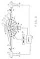
- FIG. 3Ais a side view of another embodiment of a digital magnetic system for magnetic surgery in accordance with the invention.
- FIG. 3Bis a view of a portion of the apparatus of FIG. 3A from a point along the longitudinal axis of a patient;
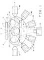
- FIG. 4is a partial transverse cross sectional view of a typical embodiment of the invention employing superconducting coils
- FIG. 5is a partial longitudinal cross sectional view of the embodiment of FIG. 4;
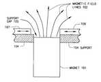
- FIG. 6is a diagram of a shutter mechanism for an individual permanent magnet to provide control of the degree of its magnetic field that reaches a point in a patient.
- FIGS. 7A and 7Bare diagrams showing how a shutter mechanism can work with two adjacent permanent magnets to provide control over the way they contribute to the field at a location in a patient, with FIG. 7A being a side view and FIG. 7B being a top view.
- FIG. 1An apparatus 10 in accordance with the invention is partially represented in FIG. 1 .
- the inventive apparatus 10comprises, in part, a fluoroscope illumination device 12 which projects a beam 13 towards fluoroscope screen 14 .
- a moveable bed 16is disposed between fluoroscope illumination device 12 and fluoroscope screen 14 .
- a patient 18(represented schematically with head 20 , oriented with his longitudinal axis extending in a direction out of the page) is shown in a supine position on bed 16 .
- Beam 13is thus projected through a treatment region 22 in the body of patient 18 so that a fluoroscopic view of this region appears on screen 14 .
- the treatment region 22shall be assumed to be located in the patient's midsection, although this will vary according to the surgical procedure being performed. It will be apparent to those skilled in the art that the apparatus could be described with respect to a treatment region 22 elsewhere in the body.
- the surface of the bed 16is rectangular and has a shorter and a longer dimension. The longer dimension would be sufficient to accommodate the length of a patient's body from head to toe. Typically, the patient will be lying on the bed in this orientation when the inventive apparatus is used to create a reference axis in the caudal-cranial direction. It should be understood, however, that an orientation of the patient or bed shape other than that described herein may be dictated by surgical requirements.
- a moving apparatus(not shown in FIG. 1) controlled by a computer or other servomechanism, (also not shown in FIG. 1) is provided so that bed 16 is moveable along at least a longitudinal axis and preferably also a transverse axis.
- the servo-controlled bedis controlled to place the treatment region between the fluoroscope illumination device 12 (or devices 12 , if more than one is provided) and the fluoroscope screen 14 (or screens 14 , if more than one is provided for multiple views of the treatment region).
- An array of electromagnets(six of which, 24 A- 24 F, are shown in FIG. 1) is provided.
- Rows of electromagnets represented by electromagnets 24 A- 24 Fare provided in sufficient number and in orientations so that, by energizing an appropriate subset of the electromagnets, a magnetic field in any orientation can be provided, at least approximately, in the treatment region of the body.
- the electromagnets 24 A- 24 Fpreferably are juxtaposed so that a field of at least 0.10 Tesla and more preferably 0.3 Tesla can be provided at any point within and to or from the regions of the abdominal cavity, chest cavity, head and arteries of a patient, depending upon the position of the bed, the translation (if any) applied to the electromagnets, and the selection of and current applied to the electromagnets.
- the electromagnetsmay be normally conducting (i.e., resistive wire electromagnets) or superconducting, the latter preferably comprising high-temperature superconductors.
- the electromagnetsare arrayed with at least one gap arranged so that the electromagnets do not obstruct the medical imaging apparatus 13 , 14 .
- FIG. 1In the cross-sectional view of FIG. 1 (which also shows, for orientation purposes, the head 20 of patient 18 ) only one electromagnet 24 A- 24 F is shown from each row. Other electromagnets, not shown, would be mounted above and below the plane of FIG. 1 . These electromagnets are mounted on or affixed to a curved shell 26 which surrounds one-half (or approximately one-half) of the treatment region from below. Shell 26 is curved, not only within the range shown in the cross-section of FIG. 1, but also in the directions into and out of the page, so that the other electromagnets in the different rows to which electromagnets 24 A- 24 F belong are also directed towards the treatment region, but along axes that cross the treatment region 22 at various angles.
- electromagnets 24 A- 24 Fprovide magnetic fields in the treatment region essentially along axes A-E in the same plane as FIG. 1, the other electromagnets, not shown, provide magnetic fields oriented in directions other than parallel with the planar section of treatment region 22 drawn in FIG. 1 .
- electromagnets 24(and 24 A- 24 F, which should be considered for purposes of discussion as being included when electromagnets 24 are referred to) is described as a shell, it is not necessary that an actual shell be used. Any suitable means for supporting the array electromagnets in a similar arrangement, preferably one that includes at least one gap between the electromagnets large enough to pass radiation from a medical imaging illuminator, may be used.
- Electromagnets 24 A- 24 Fare arrayed to have their individual axes in appropriate directions to provide, through the energizing of appropriate subsets of the electromagnets, a magnetic field needed at any place in the treatment region, directed in any needed direction.
- magnets 24 A- 24 Fare oriented to provide an array of forces that cover half of the treatment region from below.
- the magnetic fieldscan be made to provide the opposite direction of guidance, for acting on a cylindrical permanent magnet implant. That is, the magnetic field B of each coil can be reversed as needed.
- a magnetic implant 28(either a permanent magnet or an induced magnet of permeable material) inside the treatment region of the body is guided by the electromagnets 24 . It is envisioned that magnetic implant 28 is a seed for delivering therapy to a particular portion of the body of patient 18 , although it could also represent a magnetic catheter tip or other device that can be magnetically guided through the body.
- patient 18is supine on servo-controlled bed 16 , which is controlled by a computer or other servo-control element to place that portion of a body that is of interest at any given time during the medical procedure being performed below the screen 14 of a fluoroscope (or below the screen 14 of one of two or more fluoroscopes) to provide real-time imaging. Bed 16 may also, or alternately, be manually moveable for this purpose.
- the treatment region, at any particular time,includes seed 28 .
- FIG. 2shows, in schematic form, a side view of the apparatus shown in FIG. 1 .
- Electromagnets 24are shown in a plurality of rows, and include electromagnets 24 D, 24 E, and 24 F which are also shown in FIG. 1 .
- One or more electromagnets 24may be energized as necessary to provide a needed guiding field or force at each location where needed to guide magnetic seed 28 as it moves through the body.
- the magnetic fields from each energized coiladd as a vector sum, and since a plurality of coils with orientations in different directions are provided, only one or a few coils actually need to be energized to produce any required magnetic field orientation and magnitude.
- a computer 30which may be the same as the computer that guides the movement of bed 16 (if the bed is not moved manually) may be used to control the application of power to the electromagnets 24 as well as fluoroscope illuminator 12 .
- a field produced in a treatment region of body 18can be modulated by progressive activation of the subsets of the electromagnets as needed to guide or move implant 28 and/or gradual change in the currents through the energized electromagnets.
- bed 16 , shell 26 , or bothcan be moved through a servomechanism as the seed 28 moves. This action may be controlled by computer 30 .
- An example of a servo systemis shown in FIG. 2 as follows. Bed 16 is supported by stands 32 , 34 .
- Stand 34contains a servomechanism (not shown) that controls either longitudinal or transverse motion of rods 36 which carry bed 16 .
- Stand 32contains a coupling mechanism that allows rods 36 to move so that the servomechanism can smoothly move bed 16 relative to shell 26 .
- This example of a servo systemis provided only as an example, as one skilled in the art would be able to provide numerous other suitable configurations.
- a power supply 38which may actually comprise a plurality of power supplies for independently supplying individual currents to the various magnets.
- Power supply 38is (or the actual independent power supplies are) controlled by computer 30 .
- Current in each energized coil 24may be reversed as needed, if the direction of the magnetic field must be reversed.
- medical imaging device 12may also be controlled by computer 30 .
- a single row of electromagnetic coils 24is provided.
- This single rowmay be translated or rotated so as to cover, in a manner similar to that of the array shown in FIG. 2, the application of the magnetic fields to the treatment region (i.e., the operating region).
- an elongate, arcuate support 26 ′ on which magnets 24 are mountedis preferably rotatable in such a fashion that its surface traces out a curve similar to the shape of shell 26 in FIG. 2, so that the electromagnets 24 thereon can be energized in any position to provide the needed magnitude and direction of magnetic field in the treatment region of the body.
- This rotationcan be accomplished by pivoting arcuate support 26 ′ under servo control.
- this pivoting mechanismas illustrated includes rods 36 ′ that are fixedly attached to arcuate support 26 ′ at each end and that rotate within supports 32 ′ and 34 ′.
- Support 34 ′includes a motor (not shown) that is responsive to computer 30 for rotating rod 36 ′ within support 34 ′.
- arcuate support member 26 ′could be pivoted on a vertical axis, and rotated out of the plane of FIG. 3 A.
- any moveable supporting meansmay be provided, and alternate structures for providing pivoting or rotational movement of the supporting means may be provided.
- FIG. 3Bprovides another view of a portion of the embodiment of the apparatus shown in FIG. 3 A.
- the view in FIG. 3Bis from a point on a longitudinal axis of patient 18 above the head. Only one magnet 24 is shown, which, in FIG. 3B, is shown in a position essentially all the way to one side of patient 18 rather than directly below the patient, as in FIG. 3 A.
- the direction of rotation of support 26 ′is indicated by arrow A, although support 26 ′ is not itself shown in FIG. 3 B.
- FIG. 3Bprovides another view of a portion of the embodiment of the apparatus shown in FIG. 3 A.
- the view in FIG. 3Bis from a point on a longitudinal axis of patient 18 above the head. Only one magnet 24 is shown, which, in FIG. 3B, is shown in a position essentially all the way to one side of patient 18 rather than directly below the patient, as in FIG. 3 A.
- the direction of rotation of support 26 ′is indicated by arrow A, although support 26 ′
- fluoroscopic illuminating device 12may be physically coupled to support 26 ′ so that it travels with the support arm, in which case either a plurality of imaging devices 14 would have to be provided to intercept beam 13 at the various possible orientations of support 26 ′, or imaging device 14 could be mechanically or otherwise coupled to support 26 ′ so that it remains within beam 13 from illuminating device 12 as illuminating device 12 moves from position to position along with magnets 24 .
- Illuminating device 12may also be disposed in a fixed position, such as beneath bed 16 as shown in FIG. 3 A. In this case, rather than being supported by support 26 ′ as suggested by FIG. 3A, the illuminating device 12 would preferably be disposed below the lowest point of the swing of support 26 ′ so that illuminating device 12 does not interfere with the motion of support 26 ′.
- the second arrayor each of the two arrays, can comprise a single row that is translated and/or rotated about the patient to accomplish the same coverage of pulling directions.
- Such translation or rotationmay require an array to be positionable at one side of or above bed 16 , as well as being positionable under bed 16 .
- the computer controlling the currents in the electromagnetsmay calculate the combination of currents of a small cluster of the magnets in order to provide a field in any direction. Such a calculation would not be necessary when the required field is closely along the axis of one of the electromagnets, or if minor directional errors are tolerable, such as for motion within vessels. Movement of the patient bed is an additional way of providing flexibility of the available field directions.
- Individual electromagnets 24(or as represented by 24 A- 24 F) may also be made pivotable in unison about a common axis or their individual axes.
- FIG. 4shows a transverse cross-section of a portion of a typical embodiment of the invention employing a twenty coil, whole body coil arrangement of superconducting magnets 24 . Because the magnets are superconducting, only twenty are typically required, four of which are shown in FIG. 4 . (If non-superconducting coils are used, as a general rule, about twice as many would be required.)
- the magnets 24are mounted on circular shell 26 having an outside diameter B of 29 inches, and an inside diameter C of 22 inches. This arrangement is sufficient to accommodate a treatment region having a 7′′ by 15′′ cross section, as shown.
- the angle A between adjacent coils in this side viewis 60 degrees.
- FIG. 5shows a longitudinal partial cross section of the apparatus of FIG.
- electromagnets 24may be placed closer to the body to enable procedures at locations difficult to reach without more powerful magnets. To position electromagnets 24 closer to the body, their positions may be made adjustable along their respective axes. Fluoroscopic imaging may be replaced by 3-dimensional ultrasound, which might be adjusted more optimally for the adjustable electromagnets. In an extreme case, electromagnets 24 could be part of a “pelvic girdle” pushed right against a patient's body. Thin ultrasonic probes could be squeezed between the magnets to provide the necessary contact with the patient's skin. Guidance of a magnetically tipped endoscope with such a system via the optical channel of the endoscope supports the simpler visualization of the ultrasound, as compared with precision bi-plane fluoroscopy.
- inventive apparatuswhich may be used for magnetic field guidance, magnetic field control, magnetic force application, and combined guidance and force application.
- Different computer softwaremay be necessary to accomplish these or other intended purposes, as is known to those of ordinary skill in the art.
- a practical coil array and its controllerswill apply an accurately directed uniform magnetic field of a prescribed magnitude over a region of a few centimeters in diameter.
- the fieldwill apply a torque on a magnetic implant to align it in the required direction, namely along the direction of the magnetic field.
- a systemWhen operated as a magnetic control device, a system will apply an accurately directed and uniform magnetic field over one or more regions at a given time to provide some control over an implant in that region.
- One such use of the inventive systemis the stiffening of otherwise flexible permeable guide wires that are pushing an endoscope, catheter, or other therapeutic device, when the trajectory is such that the wire would tend to bow in an undesired loop.
- a system in accordance with the inventionWhen operated as a magnetic force applicator, a system in accordance with the invention would provide a uniform gradient over a small region, at times one or two centimeters in diameter, which can act on a permanent magnet implant to provide a translational force on that implant in a desired direction.
- a system in accordance with the inventionWhen operating as a combined guidance and force applicator, a system in accordance with the invention will provide the most feasible approximation to having a combination of both a transversely uniform orienting field and a longitudinal field gradient to both torque and pull in an implant in a desired direction.
- a surgeon operating a system in accordance with the inventionmay, with the aid of the imaging provided by fluoroscope screen or screens 14 , provide the guiding direction to a computer through an input such as a joy-stick.
- the computerthen would calculate the currents required to provide the guiding field at the location of the implant. Then, as the implant proceeds along a path, the surgeon would provide new directions as needed.
- the bed positionis changed smoothly by the computer to keep the implant in the imaging treatment region, or to provide more accurately directed and stronger magnetic fields if required.
- the fluoroscope or other medical imaging systemmay be used to freely view the region of approach and procedure.
- the fluoroscopemay be used by the surgeon preoperatively or in real time, and may be stereotactically connectable to the magnet system.
- the treatment implantmay be any one of numerous types of implants.
- the treatment implantmay be an endoscope with an attached magnetic implant, an endoscope with a magnetic implant contained within the endoscope, a catheter with a magnetic implant contained within or attached to it, an catheter or an endoscope with one or more magnetic sections that are to be stiffened by the applied magnetic field, or the like.
- the magnetic fieldmay be used to manipulate the direction of a leading edge of a catheter or endoscope.
- the electromagnets of the deviceare then arranged around the patient (such as by moving the bed with the patient on it into the apparatus) so that the treatment region including the treatment implant is at a location in which a magnetic field of an orientation and magnitude selected by the surgeon can be approximated by selectively energizing a subset of the electromagnets, moving the bed, or both, as required. Current is then applied to the electromagnets to approximate this field.
- the medical display in the apparatusmay be activated during this time to provide a real-time display of the procedure by directing the medical imaging illuminator through a gap in the arrangement of the electromagnets, through the treatment region, and towards an imaging screen.
- the currents in the electromagnets, and the electromagnets that are energizedmay be changed continuously to provide a time-varying magnetic field to guide the treatment implant.
- the location of the electromagnets and the location of the bedmay be moved either individually or in combination, as provided by the apparatus, under servo-control or manually, to more accurately produce the required fields in the treatment region as the treatment implant is moved.
- the general arrangement of magnets near a patientmay be similar, but with intervening permeable shutter material, or alternately, with solenoids moving the individual magnets to provide the equivalent of the above described “wavelike motion” of the field.
- FIG. 6shows the operation of shutters on a single magnet 101 , which projects field lines 102 in the direction of patient 103 (not shown to scale).
- Magnet 101is firmly mounted to non-magnetic support frame 104 , which has gap 105 .
- Sliding magnetically permeable sections 106 , 107can move over the front of gap 105 by varying amounts to control projection of magnetic field lines 102 , by providing favorable flux path to rear of magnet, shown in FIGS. 7A and 7B.
- FIG. 7Ais a side view showing the operation of shutters and flux return path on two adjacent magnets 201 and 202 mounted to nonmagnetic support 203 .
- Field lines 204 and 205emanate from magnets 201 and 202 , respectively.
- Fixed magnetically permeable lattice and return path 206has gap in front of each magnet, shown also in Top view 7 B.
- Independently sliding magnetically permeable shutters 208 , 209 , 210 and 211can by varying degrees cover all or part of one half of each circular gap in support 203 and in fixed permeable lattice 206 , as needed to control magnitude and direction (somewhat) of projected magnetic field, a combination of 204 and 205 , towards patient.
- Fixed permeable lattice 206securely contacts magnets 201 and 202 at rear, providing a return flux path much more favorable than air, so as to guide magnetic field lines controllably away from a patient in desired amounts.
- FIG. 7Bis a top view showing sliding shutters 208 , 209 , 210 and 211 covering part of gap for magnet 201 and none of gap for magnet 202 , in support 203 and lattice 206 .
- sliding shutter widths and distances between magnetsshould be such as to allow full motion of all of the shutters.
- Motions of sliding shutters 208 , 209 , 210 and 211are independent, and could be derived from rack and pinion gears driven by magnetic field immune servomotors. Sliding elements should move smoothly, and should be mounted in tracks, preferably with Teflon films to reduce friction.
- inventive apparatusestogether with the inventive methods disclosed herein, have an advantage over manually moved permanent magnets or electromagnets in that fields and forces can be applied that are accurately directed at accurately-known locations. Also provided is an advantage over the magnetic stereotaxis system and other magnetic guidance and propulsion systems in the inventive systems are much more flexible in their applications, permitting more complex and useful imaging systems to be used, in some applications stereotactically in a more effective manner.
Landscapes
- Health & Medical Sciences (AREA)
- Life Sciences & Earth Sciences (AREA)
- Surgery (AREA)
- Engineering & Computer Science (AREA)
- Veterinary Medicine (AREA)
- Public Health (AREA)
- General Health & Medical Sciences (AREA)
- Animal Behavior & Ethology (AREA)
- Nuclear Medicine, Radiotherapy & Molecular Imaging (AREA)
- Molecular Biology (AREA)
- Biomedical Technology (AREA)
- Heart & Thoracic Surgery (AREA)
- Medical Informatics (AREA)
- Pathology (AREA)
- Physics & Mathematics (AREA)
- Radiology & Medical Imaging (AREA)
- Optics & Photonics (AREA)
- Biophysics (AREA)
- Oral & Maxillofacial Surgery (AREA)
- Chemical & Material Sciences (AREA)
- Combustion & Propulsion (AREA)
- Electromagnetism (AREA)
- Power Engineering (AREA)
- Robotics (AREA)
- Magnetic Resonance Imaging Apparatus (AREA)
Abstract
Description
Claims (7)
Priority Applications (1)
| Application Number | Priority Date | Filing Date | Title |
|---|---|---|---|
| US09/911,863US6529761B2 (en) | 1997-11-12 | 2001-07-24 | Digital magnetic system for magnetic surgery |
Applications Claiming Priority (4)
| Application Number | Priority Date | Filing Date | Title |
|---|---|---|---|
| US6510497P | 1997-11-12 | 1997-11-12 | |
| US18972598A | 1998-11-10 | 1998-11-10 | |
| US09/251,164US6311082B1 (en) | 1997-11-12 | 1999-02-17 | Digital magnetic system for magnetic surgery |
| US09/911,863US6529761B2 (en) | 1997-11-12 | 2001-07-24 | Digital magnetic system for magnetic surgery |
Related Parent Applications (1)
| Application Number | Title | Priority Date | Filing Date |
|---|---|---|---|
| US09/251,164ContinuationUS6311082B1 (en) | 1997-11-12 | 1999-02-17 | Digital magnetic system for magnetic surgery |
Publications (2)
| Publication Number | Publication Date |
|---|---|
| US20020022777A1 US20020022777A1 (en) | 2002-02-21 |
| US6529761B2true US6529761B2 (en) | 2003-03-04 |
Family
ID=26745210
Family Applications (2)
| Application Number | Title | Priority Date | Filing Date |
|---|---|---|---|
| US09/251,164Expired - LifetimeUS6311082B1 (en) | 1997-11-12 | 1999-02-17 | Digital magnetic system for magnetic surgery |
| US09/911,863Expired - Fee RelatedUS6529761B2 (en) | 1997-11-12 | 2001-07-24 | Digital magnetic system for magnetic surgery |
Family Applications Before (1)
| Application Number | Title | Priority Date | Filing Date |
|---|---|---|---|
| US09/251,164Expired - LifetimeUS6311082B1 (en) | 1997-11-12 | 1999-02-17 | Digital magnetic system for magnetic surgery |
Country Status (1)
| Country | Link |
|---|---|
| US (2) | US6311082B1 (en) |
Cited By (68)
| Publication number | Priority date | Publication date | Assignee | Title |
|---|---|---|---|---|
| US20010038683A1 (en)* | 1998-11-03 | 2001-11-08 | Ritter Rogers C. | Open field system for magnetic surgery |
| US20040019447A1 (en)* | 2002-07-16 | 2004-01-29 | Yehoshua Shachar | Apparatus and method for catheter guidance control and imaging |
| US20050052178A1 (en)* | 2003-09-05 | 2005-03-10 | Siemens Aktiengeselischaft | Magnet coil system for contactless movement of a magnetic body in a working space |
| DE10341092A1 (en)* | 2003-09-05 | 2005-04-07 | Siemens Ag | Non-contact type probe device used in medical surgery, has fourteen coils for generating three magnetic field component and five magnetic field gradient from the diagonally symmetrical gradient matrices |
| US20050096589A1 (en)* | 2003-10-20 | 2005-05-05 | Yehoshua Shachar | System and method for radar-assisted catheter guidance and control |
| US20050251022A1 (en)* | 2002-09-18 | 2005-11-10 | Harvey Paul R | Method of cyclic magnetic resonance imaging |
| WO2006092421A1 (en) | 2005-03-04 | 2006-09-08 | Siemens Aktiengesellschaft | Coil system for a contactless magnetic navigation of a magnetic body in a working chamber |
| US20070016006A1 (en)* | 2005-05-27 | 2007-01-18 | Yehoshua Shachar | Apparatus and method for shaped magnetic field control for catheter, guidance, control, and imaging |
| US20070161888A1 (en)* | 2005-12-30 | 2007-07-12 | Sherman Jason T | System and method for registering a bone of a patient with a computer assisted orthopaedic surgery system |
| US20070167703A1 (en)* | 2005-12-30 | 2007-07-19 | Sherman Jason T | Method for determining a position of a magnetic source |
| US20070163367A1 (en)* | 2005-12-30 | 2007-07-19 | Sherman Jason T | Magnetic sensor array |
| US20070167741A1 (en)* | 2005-12-30 | 2007-07-19 | Sherman Jason T | Apparatus and method for registering a bone of a patient with a computer assisted orthopaedic surgery system |
| US20070197891A1 (en)* | 2006-02-23 | 2007-08-23 | Yehoshua Shachar | Apparatus for magnetically deployable catheter with MOSFET sensor and method for mapping and ablation |
| US20080154127A1 (en)* | 2006-12-21 | 2008-06-26 | Disilvestro Mark R | Method and system for registering a bone of a patient with a computer assisted orthopaedic surgery system |
| US20080249395A1 (en)* | 2007-04-06 | 2008-10-09 | Yehoshua Shachar | Method and apparatus for controlling catheter positioning and orientation |
| DE102008012342A1 (en)* | 2008-03-03 | 2009-09-10 | Siemens Aktiengesellschaft | medicine system |
| US20090275828A1 (en)* | 2008-05-01 | 2009-11-05 | Magnetecs, Inc. | Method and apparatus for creating a high resolution map of the electrical and mechanical properties of the heart |
| US20100036394A1 (en)* | 2007-01-31 | 2010-02-11 | Yoav Mintz | Magnetic Levitation Based Devices, Systems and Techniques for Probing and Operating in Confined Space, Including Performing Medical Diagnosis and Surgical Procedures |
| US20100130854A1 (en)* | 2008-11-25 | 2010-05-27 | Magnetecs, Inc. | System and method for a catheter impedance seeking device |
| US20100298845A1 (en)* | 2009-05-25 | 2010-11-25 | Kidd Brian L | Remote manipulator device |
| US20110022029A1 (en)* | 2004-12-20 | 2011-01-27 | Viswanathan Raju R | Contact over-torque with three-dimensional anatomical data |
| US20110033100A1 (en)* | 2005-02-07 | 2011-02-10 | Viswanathan Raju R | Registration of three-dimensional image data to 2d-image-derived data |
| US20110046618A1 (en)* | 2009-08-04 | 2011-02-24 | Minar Christopher D | Methods and systems for treating occluded blood vessels and other body cannula |
| US20110091853A1 (en)* | 2009-10-20 | 2011-04-21 | Magnetecs, Inc. | Method for simulating a catheter guidance system for control, development and training applications |
| US20110092808A1 (en)* | 2009-10-20 | 2011-04-21 | Magnetecs, Inc. | Method for acquiring high density mapping data with a catheter guidance system |
| US20110112396A1 (en)* | 2009-11-09 | 2011-05-12 | Magnetecs, Inc. | System and method for targeting catheter electrodes |
| US20110130718A1 (en)* | 2009-05-25 | 2011-06-02 | Kidd Brian L | Remote Manipulator Device |
| US8308628B2 (en) | 2009-11-02 | 2012-11-13 | Pulse Therapeutics, Inc. | Magnetic-based systems for treating occluded vessels |
| US8437833B2 (en) | 2008-10-07 | 2013-05-07 | Bard Access Systems, Inc. | Percutaneous magnetic gastrostomy |
| US8478382B2 (en) | 2008-02-11 | 2013-07-02 | C. R. Bard, Inc. | Systems and methods for positioning a catheter |
| US8512256B2 (en) | 2006-10-23 | 2013-08-20 | Bard Access Systems, Inc. | Method of locating the tip of a central venous catheter |
| US8774907B2 (en) | 2006-10-23 | 2014-07-08 | Bard Access Systems, Inc. | Method of locating the tip of a central venous catheter |
| US8781555B2 (en) | 2007-11-26 | 2014-07-15 | C. R. Bard, Inc. | System for placement of a catheter including a signal-generating stylet |
| US8784336B2 (en) | 2005-08-24 | 2014-07-22 | C. R. Bard, Inc. | Stylet apparatuses and methods of manufacture |
| US8801693B2 (en) | 2010-10-29 | 2014-08-12 | C. R. Bard, Inc. | Bioimpedance-assisted placement of a medical device |
| US8849382B2 (en) | 2007-11-26 | 2014-09-30 | C. R. Bard, Inc. | Apparatus and display methods relating to intravascular placement of a catheter |
| USD724745S1 (en) | 2011-08-09 | 2015-03-17 | C. R. Bard, Inc. | Cap for an ultrasound probe |
| US9125578B2 (en) | 2009-06-12 | 2015-09-08 | Bard Access Systems, Inc. | Apparatus and method for catheter navigation and tip location |
| US9211107B2 (en) | 2011-11-07 | 2015-12-15 | C. R. Bard, Inc. | Ruggedized ultrasound hydrogel insert |
| USD754357S1 (en) | 2011-08-09 | 2016-04-19 | C. R. Bard, Inc. | Ultrasound probe head |
| US9339206B2 (en) | 2009-06-12 | 2016-05-17 | Bard Access Systems, Inc. | Adaptor for endovascular electrocardiography |
| US9445734B2 (en) | 2009-06-12 | 2016-09-20 | Bard Access Systems, Inc. | Devices and methods for endovascular electrography |
| US9456766B2 (en) | 2007-11-26 | 2016-10-04 | C. R. Bard, Inc. | Apparatus for use with needle insertion guidance system |
| US9492097B2 (en) | 2007-11-26 | 2016-11-15 | C. R. Bard, Inc. | Needle length determination and calibration for insertion guidance system |
| US9521961B2 (en) | 2007-11-26 | 2016-12-20 | C. R. Bard, Inc. | Systems and methods for guiding a medical instrument |
| US9532724B2 (en) | 2009-06-12 | 2017-01-03 | Bard Access Systems, Inc. | Apparatus and method for catheter navigation using endovascular energy mapping |
| US9554716B2 (en) | 2007-11-26 | 2017-01-31 | C. R. Bard, Inc. | Insertion guidance system for needles and medical components |
| US9636031B2 (en) | 2007-11-26 | 2017-05-02 | C.R. Bard, Inc. | Stylets for use with apparatus for intravascular placement of a catheter |
| US9649048B2 (en) | 2007-11-26 | 2017-05-16 | C. R. Bard, Inc. | Systems and methods for breaching a sterile field for intravascular placement of a catheter |
| US9681823B2 (en) | 2007-11-26 | 2017-06-20 | C. R. Bard, Inc. | Integrated system for intravascular placement of a catheter |
| US9839372B2 (en) | 2014-02-06 | 2017-12-12 | C. R. Bard, Inc. | Systems and methods for guidance and placement of an intravascular device |
| US9883878B2 (en) | 2012-05-15 | 2018-02-06 | Pulse Therapeutics, Inc. | Magnetic-based systems and methods for manipulation of magnetic particles |
| US9901714B2 (en) | 2008-08-22 | 2018-02-27 | C. R. Bard, Inc. | Catheter assembly including ECG sensor and magnetic assemblies |
| US10046139B2 (en) | 2010-08-20 | 2018-08-14 | C. R. Bard, Inc. | Reconfirmation of ECG-assisted catheter tip placement |
| US10349890B2 (en) | 2015-06-26 | 2019-07-16 | C. R. Bard, Inc. | Connector interface for ECG-based catheter positioning system |
| US10449330B2 (en) | 2007-11-26 | 2019-10-22 | C. R. Bard, Inc. | Magnetic element-equipped needle assemblies |
| US10524691B2 (en) | 2007-11-26 | 2020-01-07 | C. R. Bard, Inc. | Needle assembly including an aligned magnetic element |
| US10639008B2 (en) | 2009-10-08 | 2020-05-05 | C. R. Bard, Inc. | Support and cover structures for an ultrasound probe head |
| US10751509B2 (en) | 2007-11-26 | 2020-08-25 | C. R. Bard, Inc. | Iconic representations for guidance of an indwelling medical device |
| US10820885B2 (en) | 2012-06-15 | 2020-11-03 | C. R. Bard, Inc. | Apparatus and methods for detection of a removable cap on an ultrasound probe |
| US10973584B2 (en) | 2015-01-19 | 2021-04-13 | Bard Access Systems, Inc. | Device and method for vascular access |
| US10992079B2 (en) | 2018-10-16 | 2021-04-27 | Bard Access Systems, Inc. | Safety-equipped connection systems and methods thereof for establishing electrical connections |
| US11000207B2 (en) | 2016-01-29 | 2021-05-11 | C. R. Bard, Inc. | Multiple coil system for tracking a medical device |
| US11103213B2 (en) | 2009-10-08 | 2021-08-31 | C. R. Bard, Inc. | Spacers for use with an ultrasound probe |
| US11918315B2 (en) | 2018-05-03 | 2024-03-05 | Pulse Therapeutics, Inc. | Determination of structure and traversal of occlusions using magnetic particles |
| US12171443B1 (en) | 2021-03-09 | 2024-12-24 | Pulse Therapeutics, Inc. | Magnetically controlled flow generation |
| US12369981B2 (en) | 2023-02-07 | 2025-07-29 | Depuy Ireland Unlimited Company | Systems and methods for bone model registration with adaptive soft tissue thickness |
| US12440238B2 (en) | 2021-09-09 | 2025-10-14 | C. R. Bard, Inc. | Apparatus for use with needle insertion guidance system |
Families Citing this family (67)
| Publication number | Priority date | Publication date | Assignee | Title |
|---|---|---|---|---|
| US6311082B1 (en)* | 1997-11-12 | 2001-10-30 | Stereotaxis, Inc. | Digital magnetic system for magnetic surgery |
| US6673104B2 (en)* | 2001-03-15 | 2004-01-06 | Scimed Life Systems, Inc. | Magnetic stent |
| US6934574B1 (en)* | 2001-06-21 | 2005-08-23 | Fonar Corporation | MRI scanner and method for modular patient handling |
| US6944492B1 (en) | 2001-10-01 | 2005-09-13 | Fonar Corporation | Patient bed support for an open MRI system |
| DE10203371A1 (en)* | 2002-01-29 | 2003-08-07 | Siemens Ag | Intravascular catheter with magnetic component in tip, allows magnetic field generated to be varied after introducing catheter into patient |
| US20040199072A1 (en)* | 2003-04-01 | 2004-10-07 | Stacy Sprouse | Integrated electromagnetic navigation and patient positioning device |
| US7520848B2 (en)* | 2004-04-09 | 2009-04-21 | The Board Of Trustees Of The Leland Stanford Junior University | Robotic apparatus for targeting and producing deep, focused transcranial magnetic stimulation |
| US8052591B2 (en) | 2006-05-05 | 2011-11-08 | The Board Of Trustees Of The Leland Stanford Junior University | Trajectory-based deep-brain stereotactic transcranial magnetic stimulation |
| US20110082326A1 (en)* | 2004-04-09 | 2011-04-07 | Mishelevich David J | Treatment of clinical applications with neuromodulation |
| JP4709594B2 (en)* | 2004-08-03 | 2011-06-22 | オリンパス株式会社 | Magnetic guidance medical system |
| US9352167B2 (en) | 2006-05-05 | 2016-05-31 | Rio Grande Neurosciences, Inc. | Enhanced spatial summation for deep-brain transcranial magnetic stimulation |
| US8784425B2 (en)* | 2007-02-28 | 2014-07-22 | Smith & Nephew, Inc. | Systems and methods for identifying landmarks on orthopedic implants |
| US8814868B2 (en) | 2007-02-28 | 2014-08-26 | Smith & Nephew, Inc. | Instrumented orthopaedic implant for identifying a landmark |
| EP2114263B1 (en) | 2007-02-28 | 2019-02-20 | Smith & Nephew, Inc. | System for identifying a landmark |
| DE102007013773A1 (en)* | 2007-03-22 | 2008-09-25 | Siemens Ag | Magnetically leading system, in particular medical system, in particular capsule endoscope system with prediction |
| US9289270B2 (en) | 2007-04-24 | 2016-03-22 | Medtronic, Inc. | Method and apparatus for performing a navigated procedure |
| US8734466B2 (en)* | 2007-04-25 | 2014-05-27 | Medtronic, Inc. | Method and apparatus for controlled insertion and withdrawal of electrodes |
| US8311611B2 (en)* | 2007-04-24 | 2012-11-13 | Medtronic, Inc. | Method for performing multiple registrations in a navigated procedure |
| US20090012509A1 (en)* | 2007-04-24 | 2009-01-08 | Medtronic, Inc. | Navigated Soft Tissue Penetrating Laser System |
| US8301226B2 (en)* | 2007-04-24 | 2012-10-30 | Medtronic, Inc. | Method and apparatus for performing a navigated procedure |
| US8108025B2 (en)* | 2007-04-24 | 2012-01-31 | Medtronic, Inc. | Flexible array for use in navigated surgery |
| US7753915B1 (en)* | 2007-06-14 | 2010-07-13 | August Eksler | Bi-directional bone length adjustment system |
| US8956274B2 (en)* | 2007-08-05 | 2015-02-17 | Cervel Neurotech, Inc. | Transcranial magnetic stimulation field shaping |
| AU2008288967A1 (en)* | 2007-08-20 | 2009-02-26 | Cervel NeuroTech, Inc | Firing patterns for deep brain transcranial magnetic stimulation |
| DE102007051861B4 (en)* | 2007-10-30 | 2020-03-12 | Olympus Corporation | Method for guiding a capsule endoscope and endoscope system |
| CA2706860C (en) | 2007-11-26 | 2017-08-01 | Eastern Virginia Medical School | Magnaretractor system and method |
| US9220514B2 (en) | 2008-02-28 | 2015-12-29 | Smith & Nephew, Inc. | System and method for identifying a landmark |
| US8795148B2 (en)* | 2009-10-26 | 2014-08-05 | Cervel Neurotech, Inc. | Sub-motor-threshold stimulation of deep brain targets using transcranial magnetic stimulation |
| US8723628B2 (en) | 2009-01-07 | 2014-05-13 | Cervel Neurotech, Inc. | Shaped coils for transcranial magnetic stimulation |
| CL2009000279A1 (en) | 2009-02-06 | 2009-08-14 | Biotech Innovations Ltda | Remote guidance and traction system for mini-invasive surgery, comprising: at least one surgical and removable endopinza with hooking means and a portion of ferro-magnaetic material, a cylindrical introduction guide, a detachment mechanism, and at least a means of remote traction with magnet. |
| US8945147B2 (en) | 2009-04-27 | 2015-02-03 | Smith & Nephew, Inc. | System and method for identifying a landmark |
| US9031637B2 (en)* | 2009-04-27 | 2015-05-12 | Smith & Nephew, Inc. | Targeting an orthopaedic implant landmark |
| US8086734B2 (en) | 2009-08-26 | 2011-12-27 | International Business Machines Corporation | Method of autonomic representative selection in local area networks |
| USD674093S1 (en) | 2009-08-26 | 2013-01-08 | Smith & Nephew, Inc. | Landmark identifier for targeting a landmark of an orthopaedic implant |
| US8830648B2 (en) | 2009-09-11 | 2014-09-09 | Eth Zurich | Magnetic manipulation and navigation system for a magnetic element |
| KR101814216B1 (en) | 2009-10-23 | 2018-01-02 | 가꼬우호진 시바우라 고교 다이가꾸 | Magnetic induction system and operating method for same |
| RU2012157125A (en) | 2010-06-03 | 2014-07-20 | Смит Энд Нефью, Инк. | ORTHOPEDIC IMPLANT |
| WO2012009603A2 (en) | 2010-07-16 | 2012-01-19 | Cervel Neurotech, Inc. | Transcranial magnetic stimulation for altering susceptibility of tissue to pharmaceuticals and radiation |
| WO2012103169A2 (en) | 2011-01-25 | 2012-08-02 | Smith & Nephew, Inc. | Targeting operation sites |
| RU2013153116A (en) | 2011-05-06 | 2015-06-20 | Смит Энд Нефью, Инк. | TARGETING FOR SIGNIFICANT POINTS OF ORTHOPEDIC DEVICES |
| WO2012173890A2 (en) | 2011-06-16 | 2012-12-20 | Smith & Nephew, Inc. | Surgical alignment using references |
| KR101256409B1 (en)* | 2011-08-31 | 2013-05-02 | 전남대학교산학협력단 | Actuation control system of capsule endoscope |
| EP2633831A1 (en) | 2012-02-28 | 2013-09-04 | ETH Zurich | Magnetic navigation system with soft magnetic core electromagnets for operation in the non-linear regime |
| WO2013168659A1 (en)* | 2012-05-07 | 2013-11-14 | オリンパスメディカルシステムズ株式会社 | Magnetic field generation device, and capsule-type medical device guide system |
| WO2014074475A1 (en)* | 2012-11-07 | 2014-05-15 | Emmetrope Ophthalmics Llc | Magnetic eye shields and methods of treatment and diagnosis using the same |
| CN105263391A (en)* | 2013-03-11 | 2016-01-20 | 基文影像公司 | Maneuvering coils setup for maneuvering a swallowable in-vivo device |
| US8764769B1 (en) | 2013-03-12 | 2014-07-01 | Levita Magnetics International Corp. | Grasper with magnetically-controlled positioning |
| US9333043B2 (en) | 2013-03-12 | 2016-05-10 | Fetal Care Consultants, LLC | Fetal intervention using magnetically-guided navigation |
| US10010370B2 (en) | 2013-03-14 | 2018-07-03 | Levita Magnetics International Corp. | Magnetic control assemblies and systems therefor |
| US9854991B2 (en) | 2013-03-15 | 2018-01-02 | Medtronic Navigation, Inc. | Integrated navigation array |
| US10070932B2 (en) | 2013-08-29 | 2018-09-11 | Given Imaging Ltd. | System and method for maneuvering coils power optimization |
| WO2015112645A1 (en) | 2014-01-21 | 2015-07-30 | Levita Magnetics International Corp. | Laparoscopic graspers and systems therefor |
| KR101647020B1 (en) | 2015-03-12 | 2016-08-11 | 전남대학교산학협력단 | Electromagnetic based actuation device with adjustable movement of coil-module |
| ES2895900T3 (en) | 2015-04-13 | 2022-02-23 | Levita Magnetics Int Corp | Magnetically controlled location handle |
| WO2016168377A1 (en) | 2015-04-13 | 2016-10-20 | Levita Magnetics International Corp. | Retractor systems, devices, and methods for use |
| EP3165206B1 (en) | 2015-11-06 | 2020-12-30 | Allen Medical Systems, Inc. | Subject and surgical equipment monitoring system |
| EP3399902B1 (en) | 2016-01-08 | 2024-06-12 | Levita Magnetics International Corp. | One-operator surgical system |
| EP4134991B1 (en)* | 2016-08-10 | 2024-07-10 | IUCF-HYU (Industry-University Cooperation Foundation Hanyang University) | Magnetic tube system |
| US11020137B2 (en) | 2017-03-20 | 2021-06-01 | Levita Magnetics International Corp. | Directable traction systems and methods |
| JP7515405B2 (en)* | 2018-05-18 | 2024-07-12 | マックス‐プランク‐ゲゼルシャフト・ツア・フェルデルンク・デア・ヴィッセンシャフテン・アインゲトラーゲナー・フェライン | Magnetic field generator |
| US12089910B2 (en) | 2020-05-28 | 2024-09-17 | The Chinese University Of Hong Kong | Mobile-electromagnetic coil-based magnetic actuation systems |
| US11894186B2 (en)* | 2020-06-17 | 2024-02-06 | Multi-Scale Medical Robotics Center Limited | Parallel mobile coil mechanism for magnetic manipulation in large workspace |
| KR102379538B1 (en)* | 2020-07-07 | 2022-03-28 | 재단법인 한국마이크로의료로봇연구원 | Bed-integrated electromagnetic field device for micro robot movement control and microrobot driving method using the same |
| US20240024693A1 (en)* | 2022-07-21 | 2024-01-25 | Henry Gonzalez | System for applying magnetic field to anesthetize a patient |
| KR102848978B1 (en)* | 2022-10-26 | 2025-08-21 | 주식회사 미라큐어 | Magnetic actuation system compatible with C-arm |
| KR20240103117A (en)* | 2022-12-26 | 2024-07-04 | 재단법인대구경북과학기술원 | Magnetic actuation system having curved magnetic core |
| US20250218636A1 (en)* | 2023-12-28 | 2025-07-03 | Daniel Jones | Spherical magnetic flux concentrator |
Citations (9)
| Publication number | Priority date | Publication date | Assignee | Title |
|---|---|---|---|---|
| US4875485A (en)* | 1985-11-18 | 1989-10-24 | Kabushiki Kaisha Toshiba | Magnetic resonance system |
| US5305749A (en)* | 1992-09-24 | 1994-04-26 | The Regents Of The University Of California | Side-loading of patient into MRI C-magnet while maintaining adjacent open accessibility to patient |
| US5398686A (en)* | 1992-06-30 | 1995-03-21 | Shimadzu Corporation | Magnetic resonance imaging apparatus |
| US5423315A (en)* | 1993-11-22 | 1995-06-13 | Picker International, Inc. | Magnetic resonance imaging system with thin cylindrical uniform field volume and moving subjects |
| US5636636A (en)* | 1993-09-04 | 1997-06-10 | U.S. Philips Corporation | Magnetic resonance method for imaging a moving object and device for carrying out the method |
| US5654864A (en)* | 1994-07-25 | 1997-08-05 | University Of Virginia Patent Foundation | Control method for magnetic stereotaxis system |
| US5931781A (en)* | 1996-12-18 | 1999-08-03 | U.S. Philips Corporation | MR method for the imaging of jointed movable parts |
| US5987347A (en)* | 1997-12-15 | 1999-11-16 | General Electric Company | Method for removing streak artifacts in medical images |
| US6311082B1 (en)* | 1997-11-12 | 2001-10-30 | Stereotaxis, Inc. | Digital magnetic system for magnetic surgery |
- 1999
- 1999-02-17USUS09/251,164patent/US6311082B1/ennot_activeExpired - Lifetime
- 2001
- 2001-07-24USUS09/911,863patent/US6529761B2/ennot_activeExpired - Fee Related
Patent Citations (10)
| Publication number | Priority date | Publication date | Assignee | Title |
|---|---|---|---|---|
| US4875485A (en)* | 1985-11-18 | 1989-10-24 | Kabushiki Kaisha Toshiba | Magnetic resonance system |
| US5398686A (en)* | 1992-06-30 | 1995-03-21 | Shimadzu Corporation | Magnetic resonance imaging apparatus |
| US5305749A (en)* | 1992-09-24 | 1994-04-26 | The Regents Of The University Of California | Side-loading of patient into MRI C-magnet while maintaining adjacent open accessibility to patient |
| US5305749B1 (en)* | 1992-09-24 | 2000-05-02 | Univ California | Side-loading of patient into mri c-magnet while maintaining adjacent open accessibility to patient |
| US5636636A (en)* | 1993-09-04 | 1997-06-10 | U.S. Philips Corporation | Magnetic resonance method for imaging a moving object and device for carrying out the method |
| US5423315A (en)* | 1993-11-22 | 1995-06-13 | Picker International, Inc. | Magnetic resonance imaging system with thin cylindrical uniform field volume and moving subjects |
| US5654864A (en)* | 1994-07-25 | 1997-08-05 | University Of Virginia Patent Foundation | Control method for magnetic stereotaxis system |
| US5931781A (en)* | 1996-12-18 | 1999-08-03 | U.S. Philips Corporation | MR method for the imaging of jointed movable parts |
| US6311082B1 (en)* | 1997-11-12 | 2001-10-30 | Stereotaxis, Inc. | Digital magnetic system for magnetic surgery |
| US5987347A (en)* | 1997-12-15 | 1999-11-16 | General Electric Company | Method for removing streak artifacts in medical images |
Cited By (146)
| Publication number | Priority date | Publication date | Assignee | Title |
|---|---|---|---|---|
| US20010038683A1 (en)* | 1998-11-03 | 2001-11-08 | Ritter Rogers C. | Open field system for magnetic surgery |
| US20060116634A1 (en)* | 2002-07-16 | 2006-06-01 | Yehoshua Shachar | System and method for controlling movement of a surgical tool |
| US20040019447A1 (en)* | 2002-07-16 | 2004-01-29 | Yehoshua Shachar | Apparatus and method for catheter guidance control and imaging |
| US7769427B2 (en) | 2002-07-16 | 2010-08-03 | Magnetics, Inc. | Apparatus and method for catheter guidance control and imaging |
| US7873401B2 (en) | 2002-07-16 | 2011-01-18 | Magnetecs, Inc. | System and method for a magnetic catheter tip |
| US20060116633A1 (en)* | 2002-07-16 | 2006-06-01 | Yehoshua Shachar | System and method for a magnetic catheter tip |
| US20060114088A1 (en)* | 2002-07-16 | 2006-06-01 | Yehoshua Shachar | Apparatus and method for generating a magnetic field |
| US7496396B2 (en)* | 2002-09-18 | 2009-02-24 | Koninklijke Philips Electronics N. V. | Method of cyclic magnetic resonance imaging |
| US20050251022A1 (en)* | 2002-09-18 | 2005-11-10 | Harvey Paul R | Method of cyclic magnetic resonance imaging |
| US7173507B2 (en) | 2003-09-05 | 2007-02-06 | Siemens Aktiengesellschaft | Magnet coil system for contactless movement of a magnetic body in a working space |
| US20050093544A1 (en)* | 2003-09-05 | 2005-05-05 | Gunter Ries | System for contactless moving or holding magnetic body in working space using magnet coil |
| DE10340925B3 (en)* | 2003-09-05 | 2005-06-30 | Siemens Ag | Magnetic coil system for non-contact movement of a magnetic body in a working space |
| US20050052178A1 (en)* | 2003-09-05 | 2005-03-10 | Siemens Aktiengeselischaft | Magnet coil system for contactless movement of a magnetic body in a working space |
| DE10341092A1 (en)* | 2003-09-05 | 2005-04-07 | Siemens Ag | Non-contact type probe device used in medical surgery, has fourteen coils for generating three magnetic field component and five magnetic field gradient from the diagonally symmetrical gradient matrices |
| DE10341092B4 (en)* | 2003-09-05 | 2005-12-22 | Siemens Ag | Installation for non-contact movement and / or fixation of a magnetic body in a working space using a magnetic coil system |
| US7873402B2 (en) | 2003-10-20 | 2011-01-18 | Magnetecs, Inc. | System and method for radar-assisted catheter guidance and control |
| US20050096589A1 (en)* | 2003-10-20 | 2005-05-05 | Yehoshua Shachar | System and method for radar-assisted catheter guidance and control |
| US20080027313A1 (en)* | 2003-10-20 | 2008-01-31 | Magnetecs, Inc. | System and method for radar-assisted catheter guidance and control |
| US7280863B2 (en) | 2003-10-20 | 2007-10-09 | Magnetecs, Inc. | System and method for radar-assisted catheter guidance and control |
| US8369934B2 (en) | 2004-12-20 | 2013-02-05 | Stereotaxis, Inc. | Contact over-torque with three-dimensional anatomical data |
| US20110022029A1 (en)* | 2004-12-20 | 2011-01-27 | Viswanathan Raju R | Contact over-torque with three-dimensional anatomical data |
| US7961926B2 (en) | 2005-02-07 | 2011-06-14 | Stereotaxis, Inc. | Registration of three-dimensional image data to 2D-image-derived data |
| US20110033100A1 (en)* | 2005-02-07 | 2011-02-10 | Viswanathan Raju R | Registration of three-dimensional image data to 2d-image-derived data |
| US7663458B2 (en) | 2005-03-04 | 2010-02-16 | Siemens Aktiengesellschaft | Coil system for contact-free magnetic navigation of a magnetic body in a working chamber |
| US20080272873A1 (en)* | 2005-03-04 | 2008-11-06 | Johannes Reinschke | Coil System for Contact-Free Magnetic Navigation of a Magnetic Body in a Working Chamber |
| DE102005010489B4 (en)* | 2005-03-04 | 2007-02-01 | Siemens Ag | Coil system for non-contact magnetic navigation of a magnetic body in a patient located in a working space |
| DE102005010489A1 (en)* | 2005-03-04 | 2006-09-14 | Siemens Ag | Coil system for non-contact magnetic navigation of a magnetic body in a patient located in a working space |
| WO2006092421A1 (en) | 2005-03-04 | 2006-09-08 | Siemens Aktiengesellschaft | Coil system for a contactless magnetic navigation of a magnetic body in a working chamber |
| US8027714B2 (en)* | 2005-05-27 | 2011-09-27 | Magnetecs, Inc. | Apparatus and method for shaped magnetic field control for catheter, guidance, control, and imaging |
| US20070016006A1 (en)* | 2005-05-27 | 2007-01-18 | Yehoshua Shachar | Apparatus and method for shaped magnetic field control for catheter, guidance, control, and imaging |
| US10004875B2 (en) | 2005-08-24 | 2018-06-26 | C. R. Bard, Inc. | Stylet apparatuses and methods of manufacture |
| US11207496B2 (en) | 2005-08-24 | 2021-12-28 | C. R. Bard, Inc. | Stylet apparatuses and methods of manufacture |
| US8784336B2 (en) | 2005-08-24 | 2014-07-22 | C. R. Bard, Inc. | Stylet apparatuses and methods of manufacture |
| US20070167741A1 (en)* | 2005-12-30 | 2007-07-19 | Sherman Jason T | Apparatus and method for registering a bone of a patient with a computer assisted orthopaedic surgery system |
| US8862200B2 (en) | 2005-12-30 | 2014-10-14 | DePuy Synthes Products, LLC | Method for determining a position of a magnetic source |
| US8148978B2 (en) | 2005-12-30 | 2012-04-03 | Depuy Products, Inc. | Magnetic sensor array |
| US7525309B2 (en) | 2005-12-30 | 2009-04-28 | Depuy Products, Inc. | Magnetic sensor array |
| US20070163367A1 (en)* | 2005-12-30 | 2007-07-19 | Sherman Jason T | Magnetic sensor array |
| US20070167703A1 (en)* | 2005-12-30 | 2007-07-19 | Sherman Jason T | Method for determining a position of a magnetic source |
| US20070161888A1 (en)* | 2005-12-30 | 2007-07-12 | Sherman Jason T | System and method for registering a bone of a patient with a computer assisted orthopaedic surgery system |
| US20090248014A1 (en)* | 2006-02-23 | 2009-10-01 | Magnetecs, Inc. | Apparatus for magnetically deployable catheter with mosfet sensor and method for mapping and ablation |
| US7869854B2 (en) | 2006-02-23 | 2011-01-11 | Magnetecs, Inc. | Apparatus for magnetically deployable catheter with MOSFET sensor and method for mapping and ablation |
| US20070197891A1 (en)* | 2006-02-23 | 2007-08-23 | Yehoshua Shachar | Apparatus for magnetically deployable catheter with MOSFET sensor and method for mapping and ablation |
| US9265443B2 (en) | 2006-10-23 | 2016-02-23 | Bard Access Systems, Inc. | Method of locating the tip of a central venous catheter |
| US9833169B2 (en) | 2006-10-23 | 2017-12-05 | Bard Access Systems, Inc. | Method of locating the tip of a central venous catheter |
| US9345422B2 (en) | 2006-10-23 | 2016-05-24 | Bard Acess Systems, Inc. | Method of locating the tip of a central venous catheter |
| US8858455B2 (en) | 2006-10-23 | 2014-10-14 | Bard Access Systems, Inc. | Method of locating the tip of a central venous catheter |
| US8774907B2 (en) | 2006-10-23 | 2014-07-08 | Bard Access Systems, Inc. | Method of locating the tip of a central venous catheter |
| US8512256B2 (en) | 2006-10-23 | 2013-08-20 | Bard Access Systems, Inc. | Method of locating the tip of a central venous catheter |
| US20080154127A1 (en)* | 2006-12-21 | 2008-06-26 | Disilvestro Mark R | Method and system for registering a bone of a patient with a computer assisted orthopaedic surgery system |
| US8068648B2 (en) | 2006-12-21 | 2011-11-29 | Depuy Products, Inc. | Method and system for registering a bone of a patient with a computer assisted orthopaedic surgery system |
| US20100036394A1 (en)* | 2007-01-31 | 2010-02-11 | Yoav Mintz | Magnetic Levitation Based Devices, Systems and Techniques for Probing and Operating in Confined Space, Including Performing Medical Diagnosis and Surgical Procedures |
| US20080249395A1 (en)* | 2007-04-06 | 2008-10-09 | Yehoshua Shachar | Method and apparatus for controlling catheter positioning and orientation |
| US9521961B2 (en) | 2007-11-26 | 2016-12-20 | C. R. Bard, Inc. | Systems and methods for guiding a medical instrument |
| US9526440B2 (en) | 2007-11-26 | 2016-12-27 | C.R. Bard, Inc. | System for placement of a catheter including a signal-generating stylet |
| US9999371B2 (en) | 2007-11-26 | 2018-06-19 | C. R. Bard, Inc. | Integrated system for intravascular placement of a catheter |
| US11707205B2 (en) | 2007-11-26 | 2023-07-25 | C. R. Bard, Inc. | Integrated system for intravascular placement of a catheter |
| US11529070B2 (en) | 2007-11-26 | 2022-12-20 | C. R. Bard, Inc. | System and methods for guiding a medical instrument |
| US9681823B2 (en) | 2007-11-26 | 2017-06-20 | C. R. Bard, Inc. | Integrated system for intravascular placement of a catheter |
| US11123099B2 (en) | 2007-11-26 | 2021-09-21 | C. R. Bard, Inc. | Apparatus for use with needle insertion guidance system |
| US10105121B2 (en) | 2007-11-26 | 2018-10-23 | C. R. Bard, Inc. | System for placement of a catheter including a signal-generating stylet |
| US9649048B2 (en) | 2007-11-26 | 2017-05-16 | C. R. Bard, Inc. | Systems and methods for breaching a sterile field for intravascular placement of a catheter |
| US8781555B2 (en) | 2007-11-26 | 2014-07-15 | C. R. Bard, Inc. | System for placement of a catheter including a signal-generating stylet |
| US9636031B2 (en) | 2007-11-26 | 2017-05-02 | C.R. Bard, Inc. | Stylets for use with apparatus for intravascular placement of a catheter |
| US10966630B2 (en) | 2007-11-26 | 2021-04-06 | C. R. Bard, Inc. | Integrated system for intravascular placement of a catheter |
| US8849382B2 (en) | 2007-11-26 | 2014-09-30 | C. R. Bard, Inc. | Apparatus and display methods relating to intravascular placement of a catheter |
| US9554716B2 (en) | 2007-11-26 | 2017-01-31 | C. R. Bard, Inc. | Insertion guidance system for needles and medical components |
| US12295714B2 (en) | 2007-11-26 | 2025-05-13 | C. R. Bard, Inc. | Needle assembly including an aligned magnetic element |
| US10849695B2 (en) | 2007-11-26 | 2020-12-01 | C. R. Bard, Inc. | Systems and methods for breaching a sterile field for intravascular placement of a catheter |
| US9549685B2 (en) | 2007-11-26 | 2017-01-24 | C. R. Bard, Inc. | Apparatus and display methods relating to intravascular placement of a catheter |
| US10751509B2 (en) | 2007-11-26 | 2020-08-25 | C. R. Bard, Inc. | Iconic representations for guidance of an indwelling medical device |
| US10165962B2 (en) | 2007-11-26 | 2019-01-01 | C. R. Bard, Inc. | Integrated systems for intravascular placement of a catheter |
| US10602958B2 (en) | 2007-11-26 | 2020-03-31 | C. R. Bard, Inc. | Systems and methods for guiding a medical instrument |
| US11134915B2 (en) | 2007-11-26 | 2021-10-05 | C. R. Bard, Inc. | System for placement of a catheter including a signal-generating stylet |
| US11779240B2 (en) | 2007-11-26 | 2023-10-10 | C. R. Bard, Inc. | Systems and methods for breaching a sterile field for intravascular placement of a catheter |
| US10524691B2 (en) | 2007-11-26 | 2020-01-07 | C. R. Bard, Inc. | Needle assembly including an aligned magnetic element |
| US10449330B2 (en) | 2007-11-26 | 2019-10-22 | C. R. Bard, Inc. | Magnetic element-equipped needle assemblies |
| US10342575B2 (en) | 2007-11-26 | 2019-07-09 | C. R. Bard, Inc. | Apparatus for use with needle insertion guidance system |
| US9492097B2 (en) | 2007-11-26 | 2016-11-15 | C. R. Bard, Inc. | Needle length determination and calibration for insertion guidance system |
| US10238418B2 (en) | 2007-11-26 | 2019-03-26 | C. R. Bard, Inc. | Apparatus for use with needle insertion guidance system |
| US10231753B2 (en) | 2007-11-26 | 2019-03-19 | C. R. Bard, Inc. | Insertion guidance system for needles and medical components |
| US9456766B2 (en) | 2007-11-26 | 2016-10-04 | C. R. Bard, Inc. | Apparatus for use with needle insertion guidance system |
| US8971994B2 (en) | 2008-02-11 | 2015-03-03 | C. R. Bard, Inc. | Systems and methods for positioning a catheter |
| US8478382B2 (en) | 2008-02-11 | 2013-07-02 | C. R. Bard, Inc. | Systems and methods for positioning a catheter |
| DE102008012342A1 (en)* | 2008-03-03 | 2009-09-10 | Siemens Aktiengesellschaft | medicine system |
| US20110054297A1 (en)* | 2008-03-03 | 2011-03-03 | Clemens Bulitta | Medical system |
| US20090275828A1 (en)* | 2008-05-01 | 2009-11-05 | Magnetecs, Inc. | Method and apparatus for creating a high resolution map of the electrical and mechanical properties of the heart |
| US11027101B2 (en) | 2008-08-22 | 2021-06-08 | C. R. Bard, Inc. | Catheter assembly including ECG sensor and magnetic assemblies |
| US9901714B2 (en) | 2008-08-22 | 2018-02-27 | C. R. Bard, Inc. | Catheter assembly including ECG sensor and magnetic assemblies |
| US9907513B2 (en) | 2008-10-07 | 2018-03-06 | Bard Access Systems, Inc. | Percutaneous magnetic gastrostomy |
| US8437833B2 (en) | 2008-10-07 | 2013-05-07 | Bard Access Systems, Inc. | Percutaneous magnetic gastrostomy |
| US20100130854A1 (en)* | 2008-11-25 | 2010-05-27 | Magnetecs, Inc. | System and method for a catheter impedance seeking device |
| US8457714B2 (en) | 2008-11-25 | 2013-06-04 | Magnetecs, Inc. | System and method for a catheter impedance seeking device |
| US20110130718A1 (en)* | 2009-05-25 | 2011-06-02 | Kidd Brian L | Remote Manipulator Device |
| US20100298845A1 (en)* | 2009-05-25 | 2010-11-25 | Kidd Brian L | Remote manipulator device |
| US10537713B2 (en) | 2009-05-25 | 2020-01-21 | Stereotaxis, Inc. | Remote manipulator device |
| US9125578B2 (en) | 2009-06-12 | 2015-09-08 | Bard Access Systems, Inc. | Apparatus and method for catheter navigation and tip location |
| US11419517B2 (en) | 2009-06-12 | 2022-08-23 | Bard Access Systems, Inc. | Apparatus and method for catheter navigation using endovascular energy mapping |
| US10912488B2 (en) | 2009-06-12 | 2021-02-09 | Bard Access Systems, Inc. | Apparatus and method for catheter navigation and tip location |
| US9339206B2 (en) | 2009-06-12 | 2016-05-17 | Bard Access Systems, Inc. | Adaptor for endovascular electrocardiography |
| US10271762B2 (en) | 2009-06-12 | 2019-04-30 | Bard Access Systems, Inc. | Apparatus and method for catheter navigation using endovascular energy mapping |
| US10231643B2 (en) | 2009-06-12 | 2019-03-19 | Bard Access Systems, Inc. | Apparatus and method for catheter navigation and tip location |
| US9445734B2 (en) | 2009-06-12 | 2016-09-20 | Bard Access Systems, Inc. | Devices and methods for endovascular electrography |
| US9532724B2 (en) | 2009-06-12 | 2017-01-03 | Bard Access Systems, Inc. | Apparatus and method for catheter navigation using endovascular energy mapping |
| US20110046618A1 (en)* | 2009-08-04 | 2011-02-24 | Minar Christopher D | Methods and systems for treating occluded blood vessels and other body cannula |
| US11103213B2 (en) | 2009-10-08 | 2021-08-31 | C. R. Bard, Inc. | Spacers for use with an ultrasound probe |
| US11998386B2 (en) | 2009-10-08 | 2024-06-04 | C. R. Bard, Inc. | Support and cover structures for an ultrasound probe head |
| US10639008B2 (en) | 2009-10-08 | 2020-05-05 | C. R. Bard, Inc. | Support and cover structures for an ultrasound probe head |
| US20110092808A1 (en)* | 2009-10-20 | 2011-04-21 | Magnetecs, Inc. | Method for acquiring high density mapping data with a catheter guidance system |
| US20110091853A1 (en)* | 2009-10-20 | 2011-04-21 | Magnetecs, Inc. | Method for simulating a catheter guidance system for control, development and training applications |
| US9345498B2 (en) | 2009-11-02 | 2016-05-24 | Pulse Therapeutics, Inc. | Methods of controlling magnetic nanoparticles to improve vascular flow |
| US10029008B2 (en) | 2009-11-02 | 2018-07-24 | Pulse Therapeutics, Inc. | Therapeutic magnetic control systems and contrast agents |
| US9339664B2 (en) | 2009-11-02 | 2016-05-17 | Pulse Therapetics, Inc. | Control of magnetic rotors to treat therapeutic targets |
| US11612655B2 (en) | 2009-11-02 | 2023-03-28 | Pulse Therapeutics, Inc. | Magnetic particle control and visualization |
| US11000589B2 (en) | 2009-11-02 | 2021-05-11 | Pulse Therapeutics, Inc. | Magnetic particle control and visualization |
| US10159734B2 (en) | 2009-11-02 | 2018-12-25 | Pulse Therapeutics, Inc. | Magnetic particle control and visualization |
| US8308628B2 (en) | 2009-11-02 | 2012-11-13 | Pulse Therapeutics, Inc. | Magnetic-based systems for treating occluded vessels |
| US10813997B2 (en) | 2009-11-02 | 2020-10-27 | Pulse Therapeutics, Inc. | Devices for controlling magnetic nanoparticles to treat fluid obstructions |
| US8313422B2 (en) | 2009-11-02 | 2012-11-20 | Pulse Therapeutics, Inc. | Magnetic-based methods for treating vessel obstructions |
| US8926491B2 (en) | 2009-11-02 | 2015-01-06 | Pulse Therapeutics, Inc. | Controlling magnetic nanoparticles to increase vascular flow |
| US8529428B2 (en) | 2009-11-02 | 2013-09-10 | Pulse Therapeutics, Inc. | Methods of controlling magnetic nanoparticles to improve vascular flow |
| US12370259B2 (en) | 2009-11-02 | 2025-07-29 | Pulse Therapeutics, Inc. | Magnetic particle control and visualization |
| US8715150B2 (en) | 2009-11-02 | 2014-05-06 | Pulse Therapeutics, Inc. | Devices for controlling magnetic nanoparticles to treat fluid obstructions |
| US20110112396A1 (en)* | 2009-11-09 | 2011-05-12 | Magnetecs, Inc. | System and method for targeting catheter electrodes |
| US9655539B2 (en) | 2009-11-09 | 2017-05-23 | Magnetecs, Inc. | System and method for targeting catheter electrodes |
| US10046139B2 (en) | 2010-08-20 | 2018-08-14 | C. R. Bard, Inc. | Reconfirmation of ECG-assisted catheter tip placement |
| US9415188B2 (en) | 2010-10-29 | 2016-08-16 | C. R. Bard, Inc. | Bioimpedance-assisted placement of a medical device |
| US8801693B2 (en) | 2010-10-29 | 2014-08-12 | C. R. Bard, Inc. | Bioimpedance-assisted placement of a medical device |
| USD754357S1 (en) | 2011-08-09 | 2016-04-19 | C. R. Bard, Inc. | Ultrasound probe head |
| USD724745S1 (en) | 2011-08-09 | 2015-03-17 | C. R. Bard, Inc. | Cap for an ultrasound probe |
| US9211107B2 (en) | 2011-11-07 | 2015-12-15 | C. R. Bard, Inc. | Ruggedized ultrasound hydrogel insert |
| US10646241B2 (en) | 2012-05-15 | 2020-05-12 | Pulse Therapeutics, Inc. | Detection of fluidic current generated by rotating magnetic particles |
| US9883878B2 (en) | 2012-05-15 | 2018-02-06 | Pulse Therapeutics, Inc. | Magnetic-based systems and methods for manipulation of magnetic particles |
| US10820885B2 (en) | 2012-06-15 | 2020-11-03 | C. R. Bard, Inc. | Apparatus and methods for detection of a removable cap on an ultrasound probe |
| US9839372B2 (en) | 2014-02-06 | 2017-12-12 | C. R. Bard, Inc. | Systems and methods for guidance and placement of an intravascular device |
| US10863920B2 (en) | 2014-02-06 | 2020-12-15 | C. R. Bard, Inc. | Systems and methods for guidance and placement of an intravascular device |
| US10973584B2 (en) | 2015-01-19 | 2021-04-13 | Bard Access Systems, Inc. | Device and method for vascular access |
| US10349890B2 (en) | 2015-06-26 | 2019-07-16 | C. R. Bard, Inc. | Connector interface for ECG-based catheter positioning system |
| US11026630B2 (en) | 2015-06-26 | 2021-06-08 | C. R. Bard, Inc. | Connector interface for ECG-based catheter positioning system |
| US11000207B2 (en) | 2016-01-29 | 2021-05-11 | C. R. Bard, Inc. | Multiple coil system for tracking a medical device |
| US11918315B2 (en) | 2018-05-03 | 2024-03-05 | Pulse Therapeutics, Inc. | Determination of structure and traversal of occlusions using magnetic particles |
| US11621518B2 (en) | 2018-10-16 | 2023-04-04 | Bard Access Systems, Inc. | Safety-equipped connection systems and methods thereof for establishing electrical connections |
| US10992079B2 (en) | 2018-10-16 | 2021-04-27 | Bard Access Systems, Inc. | Safety-equipped connection systems and methods thereof for establishing electrical connections |
| US12171443B1 (en) | 2021-03-09 | 2024-12-24 | Pulse Therapeutics, Inc. | Magnetically controlled flow generation |
| US12440238B2 (en) | 2021-09-09 | 2025-10-14 | C. R. Bard, Inc. | Apparatus for use with needle insertion guidance system |
| US12369981B2 (en) | 2023-02-07 | 2025-07-29 | Depuy Ireland Unlimited Company | Systems and methods for bone model registration with adaptive soft tissue thickness |
Also Published As
| Publication number | Publication date |
|---|---|
| US20020022777A1 (en) | 2002-02-21 |
| US6311082B1 (en) | 2001-10-30 |
Similar Documents
| Publication | Publication Date | Title |
|---|---|---|
| US6529761B2 (en) | Digital magnetic system for magnetic surgery | |
| US6459924B1 (en) | Articulated magnetic guidance systems and devices and methods for using same for magnetically-assisted surgery | |
| US6330467B1 (en) | Efficient magnet system for magnetically-assisted surgery | |
| US6304768B1 (en) | Method and apparatus using shaped field of repositionable magnet to guide implant | |
| US6594517B1 (en) | Method and apparatus for generating controlled torques on objects particularly objects inside a living body | |
| US6157853A (en) | Method and apparatus using shaped field of repositionable magnet to guide implant | |
| EP2255743B1 (en) | Open field system for magnetic surgery | |
| US6015414A (en) | Method and apparatus for magnetically controlling motion direction of a mechanically pushed catheter | |
| US6216026B1 (en) | Method of navigating a magnetic object, and MR device | |
| US20050182315A1 (en) | Magnetic resonance imaging and magnetic navigation systems and methods | |
| JP2000201902A (en) | Adjustable magnet for magnetic resonance imaging | |
| WO1999023946A1 (en) | Device and method for specifying magnetic field for surgical applications | |
| US20180280223A1 (en) | Robotized bed, and intraoperative mri system | |
| JP2024544740A (en) | System for guiding a magnetotactic entity within a subject - Patents.com | |
| CN111588465A (en) | A magnetic therapy graft manipulation and navigation magnetic system and method | |
| KR102697834B1 (en) | Magnetic field generating module and magnetic field generating apparatus including the module | |
| CN117693317A (en) | Endoscope magnetic guidance system and method | |
| IL262370A (en) | Operative assistance system and method for a magnetic resonance tomograph | |
| WO2022264013A1 (en) | Endoscopic magnetic guidance system and methods |
Legal Events
| Date | Code | Title | Description |
|---|---|---|---|
| FPAY | Fee payment | Year of fee payment:4 | |
| FEPP | Fee payment procedure | Free format text:PAT HOLDER NO LONGER CLAIMS SMALL ENTITY STATUS, ENTITY STATUS SET TO UNDISCOUNTED (ORIGINAL EVENT CODE: STOL); ENTITY STATUS OF PATENT OWNER: LARGE ENTITY | |
| FPAY | Fee payment | Year of fee payment:8 | |
| AS | Assignment | Owner name:SILICON VALLEY BANK, ILLINOIS Free format text:SECURITY AGREEMENT;ASSIGNOR:STEREOTAXIS, INC.;REEL/FRAME:027332/0178 Effective date:20111130 | |
| AS | Assignment | Owner name:COWEN HEALTHCARE ROYALTY PARTNERS II, L.P., AS LENDER, CONNECTICUT Free format text:SECURITY AGREEMENT;ASSIGNOR:STEREOTAXIS, INC.;REEL/FRAME:027346/0001 Effective date:20111205 Owner name:COWEN HEALTHCARE ROYALTY PARTNERS II, L.P., AS LEN Free format text:SECURITY AGREEMENT;ASSIGNOR:STEREOTAXIS, INC.;REEL/FRAME:027346/0001 Effective date:20111205 | |
| REMI | Maintenance fee reminder mailed | ||
| LAPS | Lapse for failure to pay maintenance fees | ||
| STCH | Information on status: patent discontinuation | Free format text:PATENT EXPIRED DUE TO NONPAYMENT OF MAINTENANCE FEES UNDER 37 CFR 1.362 | |
| FP | Lapsed due to failure to pay maintenance fee | Effective date:20150304 | |
| AS | Assignment | Owner name:COWEN HEALTHCARE ROYALTY PARTNERS II, L.P., CONNECTICUT Free format text:RELEASE BY SECURED PARTY;ASSIGNOR:STEREOTAXIS, INC.;REEL/FRAME:043733/0376 Effective date:20170828 Owner name:COWEN HEALTHCARE ROYALTY PARTNERS II, L.P., CONNEC Free format text:RELEASE BY SECURED PARTY;ASSIGNOR:STEREOTAXIS, INC.;REEL/FRAME:043733/0376 Effective date:20170828 | |
| AS | Assignment | Owner name:STEREOTAXIS, INC., MISSOURI Free format text:CORRECTIVE ASSIGNMENT TO CORRECT THE REVERSAL OF ASSIGNOR AND ASSIGNEE PREVIOUSLY RECORDED ON REEL 043733 FRAME 0376. ASSIGNOR(S) HEREBY CONFIRMS THE RELEASE OF SECURITY INTEREST;ASSIGNOR:COWEN HEALTHCARE ROYALTY PARTNERS II, L.P.;REEL/FRAME:044269/0282 Effective date:20170828 |