US6527962B1 - Blood filter having legs and centering elements integrally manufactured - Google Patents
Blood filter having legs and centering elements integrally manufacturedDownload PDFInfo
- Publication number
- US6527962B1 US6527962B1US09/717,556US71755600AUS6527962B1US 6527962 B1US6527962 B1US 6527962B1US 71755600 AUS71755600 AUS 71755600AUS 6527962 B1US6527962 B1US 6527962B1
- Authority
- US
- United States
- Prior art keywords
- strips
- legs
- elongated
- axis
- essentially parallel
- Prior art date
- Legal status (The legal status is an assumption and is not a legal conclusion. Google has not performed a legal analysis and makes no representation as to the accuracy of the status listed.)
- Expired - Fee Related, expires
Links
Images


Classifications
- A—HUMAN NECESSITIES
- A61—MEDICAL OR VETERINARY SCIENCE; HYGIENE
- A61F—FILTERS IMPLANTABLE INTO BLOOD VESSELS; PROSTHESES; DEVICES PROVIDING PATENCY TO, OR PREVENTING COLLAPSING OF, TUBULAR STRUCTURES OF THE BODY, e.g. STENTS; ORTHOPAEDIC, NURSING OR CONTRACEPTIVE DEVICES; FOMENTATION; TREATMENT OR PROTECTION OF EYES OR EARS; BANDAGES, DRESSINGS OR ABSORBENT PADS; FIRST-AID KITS
- A61F2/00—Filters implantable into blood vessels; Prostheses, i.e. artificial substitutes or replacements for parts of the body; Appliances for connecting them with the body; Devices providing patency to, or preventing collapsing of, tubular structures of the body, e.g. stents
- A61F2/01—Filters implantable into blood vessels
- A61F2/0103—With centering means
- A—HUMAN NECESSITIES
- A61—MEDICAL OR VETERINARY SCIENCE; HYGIENE
- A61F—FILTERS IMPLANTABLE INTO BLOOD VESSELS; PROSTHESES; DEVICES PROVIDING PATENCY TO, OR PREVENTING COLLAPSING OF, TUBULAR STRUCTURES OF THE BODY, e.g. STENTS; ORTHOPAEDIC, NURSING OR CONTRACEPTIVE DEVICES; FOMENTATION; TREATMENT OR PROTECTION OF EYES OR EARS; BANDAGES, DRESSINGS OR ABSORBENT PADS; FIRST-AID KITS
- A61F2/00—Filters implantable into blood vessels; Prostheses, i.e. artificial substitutes or replacements for parts of the body; Appliances for connecting them with the body; Devices providing patency to, or preventing collapsing of, tubular structures of the body, e.g. stents
- A61F2/01—Filters implantable into blood vessels
- A61F2/0105—Open ended, i.e. legs gathered only at one side
- A—HUMAN NECESSITIES
- A61—MEDICAL OR VETERINARY SCIENCE; HYGIENE
- A61F—FILTERS IMPLANTABLE INTO BLOOD VESSELS; PROSTHESES; DEVICES PROVIDING PATENCY TO, OR PREVENTING COLLAPSING OF, TUBULAR STRUCTURES OF THE BODY, e.g. STENTS; ORTHOPAEDIC, NURSING OR CONTRACEPTIVE DEVICES; FOMENTATION; TREATMENT OR PROTECTION OF EYES OR EARS; BANDAGES, DRESSINGS OR ABSORBENT PADS; FIRST-AID KITS
- A61F2/00—Filters implantable into blood vessels; Prostheses, i.e. artificial substitutes or replacements for parts of the body; Appliances for connecting them with the body; Devices providing patency to, or preventing collapsing of, tubular structures of the body, e.g. stents
- A61F2/82—Devices providing patency to, or preventing collapsing of, tubular structures of the body, e.g. stents
- A61F2/86—Stents in a form characterised by the wire-like elements; Stents in the form characterised by a net-like or mesh-like structure
- A61F2/90—Stents in a form characterised by the wire-like elements; Stents in the form characterised by a net-like or mesh-like structure characterised by a net-like or mesh-like structure
- A61F2/91—Stents in a form characterised by the wire-like elements; Stents in the form characterised by a net-like or mesh-like structure characterised by a net-like or mesh-like structure made from perforated sheets or tubes, e.g. perforated by laser cuts or etched holes
- A—HUMAN NECESSITIES
- A61—MEDICAL OR VETERINARY SCIENCE; HYGIENE
- A61F—FILTERS IMPLANTABLE INTO BLOOD VESSELS; PROSTHESES; DEVICES PROVIDING PATENCY TO, OR PREVENTING COLLAPSING OF, TUBULAR STRUCTURES OF THE BODY, e.g. STENTS; ORTHOPAEDIC, NURSING OR CONTRACEPTIVE DEVICES; FOMENTATION; TREATMENT OR PROTECTION OF EYES OR EARS; BANDAGES, DRESSINGS OR ABSORBENT PADS; FIRST-AID KITS
- A61F2/00—Filters implantable into blood vessels; Prostheses, i.e. artificial substitutes or replacements for parts of the body; Appliances for connecting them with the body; Devices providing patency to, or preventing collapsing of, tubular structures of the body, e.g. stents
- A61F2/01—Filters implantable into blood vessels
- A61F2002/016—Filters implantable into blood vessels made from wire-like elements
- A—HUMAN NECESSITIES
- A61—MEDICAL OR VETERINARY SCIENCE; HYGIENE
- A61F—FILTERS IMPLANTABLE INTO BLOOD VESSELS; PROSTHESES; DEVICES PROVIDING PATENCY TO, OR PREVENTING COLLAPSING OF, TUBULAR STRUCTURES OF THE BODY, e.g. STENTS; ORTHOPAEDIC, NURSING OR CONTRACEPTIVE DEVICES; FOMENTATION; TREATMENT OR PROTECTION OF EYES OR EARS; BANDAGES, DRESSINGS OR ABSORBENT PADS; FIRST-AID KITS
- A61F2/00—Filters implantable into blood vessels; Prostheses, i.e. artificial substitutes or replacements for parts of the body; Appliances for connecting them with the body; Devices providing patency to, or preventing collapsing of, tubular structures of the body, e.g. stents
- A61F2/01—Filters implantable into blood vessels
- A61F2002/018—Filters implantable into blood vessels made from tubes or sheets of material, e.g. by etching or laser-cutting
- A—HUMAN NECESSITIES
- A61—MEDICAL OR VETERINARY SCIENCE; HYGIENE
- A61F—FILTERS IMPLANTABLE INTO BLOOD VESSELS; PROSTHESES; DEVICES PROVIDING PATENCY TO, OR PREVENTING COLLAPSING OF, TUBULAR STRUCTURES OF THE BODY, e.g. STENTS; ORTHOPAEDIC, NURSING OR CONTRACEPTIVE DEVICES; FOMENTATION; TREATMENT OR PROTECTION OF EYES OR EARS; BANDAGES, DRESSINGS OR ABSORBENT PADS; FIRST-AID KITS
- A61F2230/00—Geometry of prostheses classified in groups A61F2/00 - A61F2/26 or A61F2/82 or A61F9/00 or A61F11/00 or subgroups thereof
- A61F2230/0002—Two-dimensional shapes, e.g. cross-sections
- A61F2230/0004—Rounded shapes, e.g. with rounded corners
- A61F2230/0006—Rounded shapes, e.g. with rounded corners circular
- A—HUMAN NECESSITIES
- A61—MEDICAL OR VETERINARY SCIENCE; HYGIENE
- A61F—FILTERS IMPLANTABLE INTO BLOOD VESSELS; PROSTHESES; DEVICES PROVIDING PATENCY TO, OR PREVENTING COLLAPSING OF, TUBULAR STRUCTURES OF THE BODY, e.g. STENTS; ORTHOPAEDIC, NURSING OR CONTRACEPTIVE DEVICES; FOMENTATION; TREATMENT OR PROTECTION OF EYES OR EARS; BANDAGES, DRESSINGS OR ABSORBENT PADS; FIRST-AID KITS
- A61F2230/00—Geometry of prostheses classified in groups A61F2/00 - A61F2/26 or A61F2/82 or A61F9/00 or A61F11/00 or subgroups thereof
- A61F2230/0063—Three-dimensional shapes
- A61F2230/0067—Three-dimensional shapes conical
- A—HUMAN NECESSITIES
- A61—MEDICAL OR VETERINARY SCIENCE; HYGIENE
- A61F—FILTERS IMPLANTABLE INTO BLOOD VESSELS; PROSTHESES; DEVICES PROVIDING PATENCY TO, OR PREVENTING COLLAPSING OF, TUBULAR STRUCTURES OF THE BODY, e.g. STENTS; ORTHOPAEDIC, NURSING OR CONTRACEPTIVE DEVICES; FOMENTATION; TREATMENT OR PROTECTION OF EYES OR EARS; BANDAGES, DRESSINGS OR ABSORBENT PADS; FIRST-AID KITS
- A61F2230/00—Geometry of prostheses classified in groups A61F2/00 - A61F2/26 or A61F2/82 or A61F9/00 or A61F11/00 or subgroups thereof
- A61F2230/0063—Three-dimensional shapes
- A61F2230/0069—Three-dimensional shapes cylindrical
- Y—GENERAL TAGGING OF NEW TECHNOLOGICAL DEVELOPMENTS; GENERAL TAGGING OF CROSS-SECTIONAL TECHNOLOGIES SPANNING OVER SEVERAL SECTIONS OF THE IPC; TECHNICAL SUBJECTS COVERED BY FORMER USPC CROSS-REFERENCE ART COLLECTIONS [XRACs] AND DIGESTS
- Y10—TECHNICAL SUBJECTS COVERED BY FORMER USPC
- Y10S—TECHNICAL SUBJECTS COVERED BY FORMER USPC CROSS-REFERENCE ART COLLECTIONS [XRACs] AND DIGESTS
- Y10S623/00—Prosthesis, i.e. artificial body members, parts thereof, or aids and accessories therefor
- Y10S623/901—Method of manufacturing prosthetic device
Definitions
- the inventionrelates to a process for manufacturing a blood filter adapted to be disposed within a blood vessel of a mammal body.
- a specific blood filteris also concerned.
- elongated legsare typically created, together with at least a head for joining the legs together, locally.
- the legstypically extend round an axis of the filter and are radially movable with respect to the axis and the head, between a first, radially restricted position and a second, radially expanded position in which the legs are diverging from the axis (located farer therefrom than in the first position, along a portion of their length).
- An object of the inventionis to improve the steps of manufacturing blood filter.
- an important feature of the inventionrecommends to make use of the following steps of manufacturing:
- step (c)in at least some of the wall sections materialized during the above-mentioned step (b), adjacent, essentially parallel strips (having a non circular transversal section) are created, said strips comprising at least a first strip and a second strip separated by a slot, the strips extending essentially parallel the axis and the slots interrupting at a distance from the first free end of the corresponding wall sections, so that the first strips are integral with the second strips at said first free end, while the second strips are freely movable from the first strips all along the slots (and especially at the second end of the wall sections),
- the inventionpreferably recommends a further step of angularly shifting the second strips with respect to the first strips, so that in the second position, the first strips are angulated with respect to the axis of the blood filter, while the second strips extend substantially parallel the axis.
- the stripscan be mechanically moved or a thermal treatment together with a shape-memory material, such as a super-elastic metallic alloy (NiTi) can be used for shifting said strips and for having the first strips moved between the first and second positions.
- a shape-memory materialsuch as a super-elastic metallic alloy (NiTi)
- NiTisuper-elastic metallic alloy
- step (a)For improving the reliability of the filter while limiting the costs of manufacturing, it is further recommended, during the step (a), to use an essentially tubular wall and, during step (b), to connect all the first strips one to the others by using a connecting element to which every first strip is fixed, at said second end, the first strips being regularly disposed round the axis.
- the wall sections ⁇ cut>> in the original wallindividually have the shape of a plate (showing a non circular section) and comprise at least two strips separated by a slot which is interrupted at a distance from the first end, so that the first strips are integral with the second strips at said first end, so that said firststrips define the legs of the blood filter and the second strips define centering elements for centering the blood filter within the blood vessel.
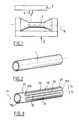
- FIG. 1diagrammatically shows a laser cutting machine adapted for cutting the tube shown on
- FIG. 2(enlarged view)
- FIG. 3diagrammatically shows the tube of FIG. 2 after the cutting process
- FIG. 4shows a partial view of a filter manufactured according to the invention, the filter being in its radially expanded position (enlarged view),
- FIG. 5shows a way for obtaining a blood filter according to the invention from a flat plate such as illustrated on FIG. 6,
- FIGS. 7 and 8diagrammatically show two solutions for maintaining the head of the filter in a curved position round the axis of said filter
- FIGS. 9, 10 and 11diagrammatically show three embodiments of the legs and centering elements of the blood filter
- FIG. 12diagrammatically shows how to cut the shape illustrated on FIG. 9, from a thin tubular wall
- FIG. 13shows an invaginated tubular wall.
- FIG. 1a laser cutting machine is shown. Such a machine can be used for manufacturing a blood filter from a continuous, solid wall having the shape of a tube.
- a thin, essentially tubular wall having a small diameter(such as a cylindrical, metallic tube having a constant section, as referenced 1 on FIG. 2) is disposed round a rotatable mandrel 3 of a numerally driven machine 5 provided with a shaft 7 having a laser 9 , such as a Nd laser.
- Tube 1is disposed round the mandrel 3 , then rotated and longitudinally moved (along the axis 11 ) with respect to the laser beam. Portions of the tube material are selectively removed by the laser beam, according to the required shape which presently corresponds to the diagrammatical illustration of FIG. 3 .
- Cutting the wallcan be operated by using another process: for example, the wall can be ⁇ cut>> by chemical etching or by a hot knife, or even by using a CO 2 laser (see U.S. Pat. No. 5,421,955, column 6, line 31-column 7, line 32).
- a chemical etching processis disclosed in EP-A-0 709 067 (column 2, line 38-column 3, line 28).
- the blood filtercomprises elongated, essentially parallel sections of wall, such as referenced 13 and 15 .
- the elongated sectionsare essentially parallel the longitudinal axis 17 of the filter (which corresponds to the axis 11 of the tube).
- the elongated sections 13 , 15are regularly disposed round the axis.
- the elongated section 13comprises two strips of wall 19 , 21 , separated by a slot 23 essentially parallel the axis 17 .
- Slot 23is interrupted at a distance from the free end 19 a of the first strip 19 , while it opens at the opposed end, 21 b , so that the two strips 19 , 21 are connected (or joined) only near, or at, the free end 19 a (by a zone of wall 25 ), while said strips are free of moving one with respect to the other, along the slot 23 (and especially at the end 21 b which thus defines a free end for the second strip 21 ).
- proximal end of the filteropposed to the above-mentioned ⁇ free end>> 19 a (also called distal end), is referenced 19 b , it will further be noted that all the ⁇ first strips>>, such as 19 , are connected (or joined) together by a connecting means which is presently defined by a strip (or band) 27 of wall extending transversally (especially perpendicular) the axis 17 along which the wall section and strips extend.
- the strip 27is integral with all the first strips (such as 19 ) and connects them one to the other, in the immediate vicinity of the proximal end 19 b.
- FIG. 4an illustration more in conformity with a real blood filter than the illustration of FIG. 3, is shown. However, only some of the wall sections as cut are illustrated, for sake of clarity.
- the blood filtercan be considered as illustrated in its ⁇ radially restricted state>>, (viz. the state it holds within the introducing catheter), whereas on FIG. 4, the filter is in its ⁇ radially expanded stated >>, viz. as it holds within the vessel for filtering any blood clots therein.
- the first strips of the wallsuch as 19
- the ⁇ second strips>> 21define centering (or stabilizing) integrated elements.
- the angulation ⁇in such a radially expanded state, of the legs such as 19 with respect to the axis 17 , may be of about 30° to 40°.
- the angulation ⁇is substantially identical to angulation ⁇ corresponding to the angulation between the legs and the centering elements (which have to be directed parallel the axis 17 , along a generating line of cylinder having a constant section).
- the apex of angulation ⁇is located at the proximal end 19 b of the filter (typically called ⁇ filter head>>).
- the cone of filtration defined by the legsopens up to the distal end 19 a where the legs are far away one from the others, in the radially expanded state of FIG. 4 .
- the following material (or covering)can be cited for the original wall 1: stainless steel, nitinol® which is a super elastic alloy having a thermal memory shape, titanium, or even plastic material (such as thermoplastic polymer). So, the state illustrated on FIG. 4 can be reached by the natural elasticity of the strips 19 , 21 , or further to a variation of temperature if a thermal memory alloy is used.
- the first strips, such as 19are connected to one another, near the end 19 b , by using a complementary member 29 .
- the anchorssuch as 31 a , 31 b , are integrated to the centering elements 21 .
- the complementary member 29is a metallic, partially hollow cap within which the legs are welded. With such a connection, the legs 19 , before being connected one to the other by the cap 29 , are independent. Those independent legs (which then have a free end 19 c ) are disposed in a close position at said end and are connected to the cap 29 which thus, define the connecting head of the legs.
- FIG. 5shows an embodiment (not the best mode) for manufacturing the filter illustrated on FIG. 4, from a flat plate, such as the plate referenced 30 on FIG. 6 .
- the flat wall 30is already ⁇ cut>>, viz. slots defining the strips having a plate shape (thus showing a non circular section) have been created for defining the legs and integrated centering elements of the filter.
- the parallel wall sections defined by the cuts of the platebegin from the upper connecting band 27 .
- the resulting parallel wall sectionssuch as those referenced 13 , 15 , one more time, comprise a first strip 19 having a reduced width referenced 33 a , 33 b , said first strip extending at the axial end 19 a (opposite the band 27 ) by a second strip (such as 21 ) integral with the first strip (the hairpin connection zone between the first and second strips is referenced 25 ).
- the second stripshave also a reduced width for defining the corresponding integrated anchors, such as 31 a , 31 b.
- the second strips 21are interrupted at a distance from the end, so that the second ( ⁇ backward>>) strips are shorter than the first ( ⁇ frontward>>) strips.
- hollow spaces, such as 36 a , 36 bare materialized through the wall.
- the first strips 19are angularly shifted with respect to the transversal band 27 , whereas the second strips 21 are maintained substantially parallel the axis 17 .
- the resulting shapeis rolled on itself round the axis 17 .
- a blood filterhaving elongated legs showing the shape of a substantially frustoconical shape, having an axial opening through its band 27 (head) and a free end 19 a where, in such a radially expanded state, the filter shows its larger diameter, is created.
- a welding 35can be used for maintaining the filter rolled on itself, at its head zone 27 , where the two opposed ends 37 a , 37 b of the wall can overlap, as illustrated on FIG. 7 .
- FIG. 8shows that those two ends can face each other, with no fixation means therebetween.
- FIGS. 9, 10 and 11are diagrammatically illustrated some among other possible shapes for the legs and centering elements of the blood filter.
- a ⁇ W>> shapeis shown comprising two lateral strips 39 defining the legs of the filter.
- Each strip 39is integral with a central centering member 41 having the shape of an inverted ⁇ V>>.
- Two slots 40 a , 40 bdefine an inverted ⁇ V>>, so that they are essentially parallel to the axis 42 .
- Such shapescan be created for example from the tube 43 of FIG. 12 in which strips are cut as illustrated, the strips being thereafter slightly angularly shifted for obtaining the required filter shape.
- FIG. 10On FIG. 10 is illustrated a central elongated leg having a zigzag shape (so essentially parallel to the axis 47 of the filter). Said elongated leg 45 is integrally connected with two lateral centering members 47 a , 47 b , at the end 45 a.
- two legs 49 , 51are diagrammatically illustrated. Those two legs are integrally connected with a continuous, transversal band 53 and extend, at an end opposite said band (respectively referenced 49 a and 51 a ), in centering members having an inverted ⁇ V>> shape, respectively referenced 149 and 151 .
- tubular wall of FIG. 2could be changed to an invaginated tubular wall 60 (especially a frustoconical wall) such as the wall illustrated on FIG. 13 .
Landscapes
- Health & Medical Sciences (AREA)
- Cardiology (AREA)
- Oral & Maxillofacial Surgery (AREA)
- Transplantation (AREA)
- Engineering & Computer Science (AREA)
- Biomedical Technology (AREA)
- Heart & Thoracic Surgery (AREA)
- Vascular Medicine (AREA)
- Life Sciences & Earth Sciences (AREA)
- Animal Behavior & Ethology (AREA)
- General Health & Medical Sciences (AREA)
- Public Health (AREA)
- Veterinary Medicine (AREA)
- Filtering Materials (AREA)
- Prostheses (AREA)
- Filtration Of Liquid (AREA)
- Surgical Instruments (AREA)
Abstract
Description
The invention relates to a process for manufacturing a blood filter adapted to be disposed within a blood vessel of a mammal body. A specific blood filter is also concerned.
Blood filters are already known.
For manufacturing blood filters, elongated legs are typically created, together with at least a head for joining the legs together, locally. The legs typically extend round an axis of the filter and are radially movable with respect to the axis and the head, between a first, radially restricted position and a second, radially expanded position in which the legs are diverging from the axis (located farer therefrom than in the first position, along a portion of their length).
Examples of such blood filters can be found in U.S. Pat. No. 4,688,553 or U.S. Pat. No. 5,344,427.
So, the prior art discloses the following steps for manufacturing a blood filter:
(a) using a wall comprising a biocompatible material, and
(b) for defining the legs of the blood filter, creating through said wall a series of elongated, essentially parallel sections having a first free end and a second opposed end.
An object of the invention is to improve the steps of manufacturing blood filter.
The following objects are especially expected:
reducing the steps of assembling the different portions of the filter (legs, head . . . ),
reducing the risks possibly induced by local, mechanical constraints created during the steps of manufacturing the blood filter,
improving the cohesion between the above-mentioned different portions of the filter,
potentially reducing the costs for manufacturing the filter,
using possible synergies between the blood filters and the stents or stent grafts.
To that aim, an important feature of the invention recommends to make use of the following steps of manufacturing:
(c) in at least some of the wall sections materialized during the above-mentioned step (b), adjacent, essentially parallel strips (having a non circular transversal section) are created, said strips comprising at least a first strip and a second strip separated by a slot, the strips extending essentially parallel the axis and the slots interrupting at a distance from the first free end of the corresponding wall sections, so that the first strips are integral with the second strips at said first free end, while the second strips are freely movable from the first strips all along the slots (and especially at the second end of the wall sections),
(d) and the first strips are connected therebetween, at the second end.
Even if reducing the mechanical constraints within the blood filter as manufactured is an important object, the invention preferably recommends a further step of angularly shifting the second strips with respect to the first strips, so that in the second position, the first strips are angulated with respect to the axis of the blood filter, while the second strips extend substantially parallel the axis.
It is to be noted that such an <<angular shifting>> is typically comprised between 30° and 40°, what induces less mechanical constraints in the blood filter than folding back sections of a metallic wire for forming an air pin, as disclosed in U.S. Pat. Nos. 4,688,553, 5,344,427 or 5,383,887.
Further, welding a wire and a metallic plate as in FR-A-2 764 503 is avoided.
For angularly shifting the corresponding strips, the strips can be mechanically moved or a thermal treatment together with a shape-memory material, such as a super-elastic metallic alloy (NiTi) can be used for shifting said strips and for having the first strips moved between the first and second positions.
For improving the reliability of the filter while limiting the costs of manufacturing, it is further recommended, during the step (a), to use an essentially tubular wall and, during step (b), to connect all the first strips one to the others by using a connecting element to which every first strip is fixed, at said second end, the first strips being regularly disposed round the axis.
With reference to the blood filter, the following distinctive features are to be noted: the wall sections <<cut>> in the original wall individually have the shape of a plate (showing a non circular section) and comprise at least two strips separated by a slot which is interrupted at a distance from the first end, so that the first strips are integral with the second strips at said first end, so that said firststrips define the legs of the blood filter and the second strips define centering elements for centering the blood filter within the blood vessel.
FIG. 1 diagrammatically shows a laser cutting machine adapted for cutting the tube shown on
FIG. 2 (enlarged view),
FIG. 3 diagrammatically shows the tube of FIG. 2 after the cutting process,
FIG. 4 shows a partial view of a filter manufactured according to the invention, the filter being in its radially expanded position (enlarged view),
FIG. 5 shows a way for obtaining a blood filter according to the invention from a flat plate such as illustrated on FIG. 6,
FIGS. 7 and 8 diagrammatically show two solutions for maintaining the head of the filter in a curved position round the axis of said filter,
FIGS. 9,10 and11 diagrammatically show three embodiments of the legs and centering elements of the blood filter,
FIG. 12 diagrammatically shows how to cut the shape illustrated on FIG. 9, from a thin tubular wall, and
FIG. 13 shows an invaginated tubular wall.
On FIG. 1, a laser cutting machine is shown. Such a machine can be used for manufacturing a blood filter from a continuous, solid wall having the shape of a tube.
Laser cutting is already disclosed in EP-B-0 714 641 (column 9, line 24-column 10, line 9): a thin, essentially tubular wall having a small diameter (such as a cylindrical, metallic tube having a constant section, as referenced1 on FIG. 2) is disposed round arotatable mandrel 3 of a numerally drivenmachine 5 provided with ashaft 7 having alaser 9, such as a Nd laser. Tube1 is disposed round themandrel 3, then rotated and longitudinally moved (along the axis11) with respect to the laser beam. Portions of the tube material are selectively removed by the laser beam, according to the required shape which presently corresponds to the diagrammatical illustration of FIG.3.
Cutting the wall can be operated by using another process: for example, the wall can be <<cut>> by chemical etching or by a hot knife, or even by using a CO2laser (see U.S. Pat. No. 5,421,955, column 6, line 31-column 7, line 32). A chemical etching process is disclosed in EP-A-0 709 067 (column 2, line 38-column 3, line 28).
On FIG. 3, the blood filter comprises elongated, essentially parallel sections of wall, such as referenced13 and15. The elongated sections are essentially parallel thelongitudinal axis 17 of the filter (which corresponds to theaxis 11 of the tube).
Angularly, theelongated sections
Therefore, what is true in the present description with reference to a specific elongated section (such as referenced13) is also true for the other elongated sections. Theelongated section 13 comprises two strips ofwall slot 23 essentially parallel theaxis 17.Slot 23 is interrupted at a distance from thefree end 19aof thefirst strip 19, while it opens at the opposed end,21b, so that the twostrips free end 19a(by a zone of wall25), while said strips are free of moving one with respect to the other, along the slot23 (and especially at theend 21bwhich thus defines a free end for the second strip21).
If the proximal end of the filter, opposed to the above-mentioned <<free end>>19a(also called distal end), is referenced19b, it will further be noted that all the <<first strips>>, such as19, are connected (or joined) together by a connecting means which is presently defined by a strip (or band)27 of wall extending transversally (especially perpendicular) theaxis 17 along which the wall section and strips extend. Thestrip 27 is integral with all the first strips (such as19) and connects them one to the other, in the immediate vicinity of theproximal end 19b.
On FIG. 4, an illustration more in conformity with a real blood filter than the illustration of FIG. 3, is shown. However, only some of the wall sections as cut are illustrated, for sake of clarity.
It is also to be noted that on FIG. 3, the blood filter can be considered as illustrated in its <<radially restricted state>>, (viz. the state it holds within the introducing catheter), whereas on FIG. 4, the filter is in its <<radially expanded stated >>, viz. as it holds within the vessel for filtering any blood clots therein.
Especially on FIG. 4, it is shown that the first strips of the wall, such as19, define legs which are inclined with respect toaxis 17, whereas the <<second strips>>21 define centering (or stabilizing) integrated elements.
The angulation α, in such a radially expanded state, of the legs such as19 with respect to theaxis 17, may be of about 30° to 40°. The angulation α is substantially identical to angulation β corresponding to the angulation between the legs and the centering elements (which have to be directed parallel theaxis 17, along a generating line of cylinder having a constant section).
The apex of angulation α is located at theproximal end 19bof the filter (typically called <<filter head>>). The cone of filtration defined by the legs opens up to thedistal end 19awhere the legs are far away one from the others, in the radially expanded state of FIG.4.
The following material (or covering) can be cited for the original wall 1: stainless steel, nitinol® which is a super elastic alloy having a thermal memory shape, titanium, or even plastic material (such as thermoplastic polymer). So, the state illustrated on FIG. 4 can be reached by the natural elasticity of thestrips
Two structural differences can be found between the illustrations of FIGS.3 and4: on FIG. 4, the first strips, such as19, are connected to one another, near theend 19b, by using acomplementary member 29. Further, the anchors such as31a,31b, are integrated to the centeringelements 21.
Thecomplementary member 29 is a metallic, partially hollow cap within which the legs are welded. With such a connection, thelegs 19, before being connected one to the other by thecap 29, are independent. Those independent legs (which then have afree end 19c) are disposed in a close position at said end and are connected to thecap 29 which thus, define the connecting head of the legs.
The creation of the integrated anchors31a,31bis clearly illustrated on FIG. 5 which shows an embodiment (not the best mode) for manufacturing the filter illustrated on FIG. 4, from a flat plate, such as the plate referenced30 on FIG.6.
On FIG. 5, theflat wall 30 is already <<cut>>, viz. slots defining the strips having a plate shape (thus showing a non circular section) have been created for defining the legs and integrated centering elements of the filter.
On FIG. 5, the parallel wall sections defined by the cuts of the plate begin from the upper connectingband 27. The resulting parallel wall sections, such as those referenced13,15, one more time, comprise afirst strip 19 having a reduced width referenced33a,33b, said first strip extending at theaxial end 19a(opposite the band27) by a second strip (such as21) integral with the first strip (the hairpin connection zone between the first and second strips is referenced25).
At the level of the reducedwidth
Towards theproximal end 19b, thesecond strips 21 are interrupted at a distance from the end, so that the second (<<backward>>) strips are shorter than the first (<<frontward>>) strips. Thus, hollow spaces, such as36a,36bare materialized through the wall.
After having created such a shape, thefirst strips 19 are angularly shifted with respect to thetransversal band 27, whereas thesecond strips 21 are maintained substantially parallel theaxis 17.
Before that step, or after, the resulting shape is rolled on itself round theaxis 17.
Thus, a blood filter having elongated legs showing the shape of a substantially frustoconical shape, having an axial opening through its band27 (head) and afree end 19awhere, in such a radially expanded state, the filter shows its larger diameter, is created.
Awelding 35 can be used for maintaining the filter rolled on itself, at itshead zone 27, where the two opposed ends37a,37bof the wall can overlap, as illustrated on FIG.7.
Alternatively, FIG. 8 shows that those two ends can face each other, with no fixation means therebetween.
On FIGS. 9,10 and11, are diagrammatically illustrated some among other possible shapes for the legs and centering elements of the blood filter.
So, on FIG. 9, a <<W>> shape is shown comprising twolateral strips 39 defining the legs of the filter. Eachstrip 39 is integral with a central centeringmember 41 having the shape of an inverted <<V>>. Twoslots axis 42.
Such shapes can be created for example from thetube 43 of FIG. 12 in which strips are cut as illustrated, the strips being thereafter slightly angularly shifted for obtaining the required filter shape.
On FIG. 10 is illustrated a central elongated leg having a zigzag shape (so essentially parallel to the axis47 of the filter). Saidelongated leg 45 is integrally connected with two lateral centeringmembers end 45a.
On FIG. 11, twolegs transversal band 53 and extend, at an end opposite said band (respectively referenced49aand51a), in centering members having an inverted <<V>> shape, respectively referenced149 and151.
Those examples show that various shapes can be created for the legs and the centering elements (or members) of the filter. An important feature is to draw one or a series of leg(s) and centering element(s) from an original wall in which the required shape is <<cut>> (viz. created), together with at least one slot essentially parallel the axis of the blood filter (which axis can be considered as the same than the axis of the blood vessel, once the filter is implanted in said vessel).
It is further to be noted that the tubular wall of FIG. 2 could be changed to an invaginated tubular wall60 (especially a frustoconical wall) such as the wall illustrated on FIG.13.
Claims (6)
1. A method for manufacturing a blood filter adapted to be disposed in a blood vessel, the blood filter having an axis and comprising elongated legs extending around the axis, the method comprising the steps of:
a) providing a thin wall comprising a biocompatible material,
b) from the thin wall, producing a series of essentially parallel elongated sections, for defining the elongated legs, the elongated sections having a longitudinal first end and a longitudinal second end,
c) joining the elongated legs to each other, at the first end of the elongated sections, so that the elongated legs are radially movable between a first position in which the legs are radially expanded and a second position in which the legs are radially restricted,
wherein step b) comprises the step of:
d) in at least some of said parallel elongated sections, producing adjacent essentially parallel strips comprising a first strip and a second strip separated by a slot, the strips extending essentially parallel the axis and each slot being interrupted at a distance from the second end, so that the first and the second strips are connected to each other at the second end, by a continuous zone of said thin wall,
and wherein step c) comprises the step of:
e) joining the first strip of the elongated sections to each other, at said first end thereof.
2. The method ofclaim 1 , further comprising the step of:
f) angularly shifting one with respect to the other, the respective first and second strips of the elongated sections, so that the first strips connected to each other at said first end define the elongated legs of the blood filter and are angulated with respect to the axis, in the second position, and the second strips are oriented essentially parallel the axis in said second position.
3. A method for manufacturing a blood filter adapted to be disposed in a blood vessel, the blood filter having an axis and comprising elongated legs extending around the axis, the method comprising the steps of:
a) providing a thin wall comprising a biocompatible material and having a tubular surface,
b) from the thin wall, producing a series of essentially parallel elongated sections, for defining the elongated legs, the elongated legs having a free end and being radially movable between a first position in which the legs are radially expanded and a second position in which they are radially restricted,
wherein step b) further comprises the steps of:
c) in at least some of said parallel elongated sections producing adjacent essentially parallel strips comprising a first strip and a second strip separated by a slot, the strips extending essentially parallel the axis and each slot being interrupted at a distance from the free end, so that the first and the second strips are connected to each other at said free end, by a continuous zone of the thin wall,
d) on said thin wall, at an end opposite said free end, keeping a connecting section extending transversal the elongated sections which are thus integral with said transversal section, so that the elongated legs are joined to each other around the axis by the transversal section.
4. A method for manufacturing a blood filter adapted to be disposed in a blood vessel, the blood filter having an axis and comprising elongated legs extending around the axis, the method comprising the steps of:
a) providing a thin wall comprising a biocompatible material, and having a non-tubular surface,
b) producing a series of essentially parallel elongated sections from the thin wall, for defining the elongated legs, the elongated legs having a free end and being radially movable between a first position in which the legs are radially expanded and a second position in which they are radially restricted, wherein step b) further comprises the steps of:
c) producing adjacent essentially parallel strips comprising a first strip and a second strip separated by a slot, in at least some of said parallel elongated sections, the strips extending essentially parallel the axis and each slot being interrupted at a distance from the free end, so that the first and the second strips are connected to each other at said free end, by a continuous zone of said thin wall,
d) on the thin wall and at an end opposite said free end, keeping a connecting section extending transversal the elongated sections which are thus integral with said transversal section, so that the elongated legs are joined to each other by the transversal section, and
e) rolling the transversal section and the parallel elongated sections around the axis.
5. The method according toclaim 1 , wherein the step b) comprises the step of producing the series of essentially parallel elongated sections by cutting the thin wall with a laser beam.
6. The method according toclaim 1 , wherein the step b) comprises the step of producing the series of essentially parallel elongated sections by chemical etching.
Applications Claiming Priority (2)
| Application Number | Priority Date | Filing Date | Title |
|---|---|---|---|
| FR9914900 | 1999-11-26 | ||
| FR9914900AFR2801493B1 (en) | 1999-11-26 | 1999-11-26 | METHOD FOR MANUFACTURING A MONOBLOCK BLOOD FILTER |
Publications (1)
| Publication Number | Publication Date |
|---|---|
| US6527962B1true US6527962B1 (en) | 2003-03-04 |
Family
ID=9552577
Family Applications (1)
| Application Number | Title | Priority Date | Filing Date |
|---|---|---|---|
| US09/717,556Expired - Fee RelatedUS6527962B1 (en) | 1999-11-26 | 2000-11-21 | Blood filter having legs and centering elements integrally manufactured |
Country Status (5)
| Country | Link |
|---|---|
| US (1) | US6527962B1 (en) |
| EP (1) | EP1103233B1 (en) |
| DE (1) | DE60021836T2 (en) |
| ES (1) | ES2244399T3 (en) |
| FR (1) | FR2801493B1 (en) |
Cited By (75)
| Publication number | Priority date | Publication date | Assignee | Title |
|---|---|---|---|---|
| US6783538B2 (en) | 2001-06-18 | 2004-08-31 | Rex Medical, L.P | Removable vein filter |
| US6793665B2 (en) | 2001-06-18 | 2004-09-21 | Rex Medical, L.P. | Multiple access vein filter |
| US20040230220A1 (en)* | 2003-02-11 | 2004-11-18 | Cook Incorporated | Removable vena cava filter |
| US20050004596A1 (en)* | 2001-06-18 | 2005-01-06 | Mcguckin James F. | Vein filter |
| US20050015111A1 (en)* | 2001-06-18 | 2005-01-20 | Mcguckin James F. | Vein filter |
| US20050055046A1 (en)* | 2001-06-18 | 2005-03-10 | Rex Medical | Removable vein filter |
| US20050165442A1 (en)* | 2004-01-22 | 2005-07-28 | Thinnes John H.Jr. | Vein filter |
| US20050165441A1 (en)* | 2004-01-22 | 2005-07-28 | Mcguckin James F.Jr. | Vein filter |
| US20050209632A1 (en)* | 2004-01-14 | 2005-09-22 | Wallace Michael J | Filtering devices |
| US20050251199A1 (en)* | 2004-04-16 | 2005-11-10 | Osborne Thomas A | Removable vena cava filter with anchoring feature for reduced trauma |
| US20050267513A1 (en)* | 2004-04-16 | 2005-12-01 | Osborne Thomas A | Removable vena cava filter having primary struts for enhanced retrieval and delivery |
| US20050267512A1 (en)* | 2004-04-16 | 2005-12-01 | Osborne Thomas A | Removable vena cava filter for reduced trauma in collapsed configuration |
| US20060069406A1 (en)* | 2004-09-27 | 2006-03-30 | Per Hendriksen | Removable vena cava filter comprising struts having axial bends |
| US20060203769A1 (en)* | 2005-03-11 | 2006-09-14 | Saholt Douglas R | Intravascular filter with centering member |
| US20060224175A1 (en)* | 2005-03-29 | 2006-10-05 | Vrba Anthony C | Methods and apparatuses for disposition of a medical device onto an elongate medical device |
| US20070005095A1 (en)* | 2004-04-16 | 2007-01-04 | Osborne Thomas A | Removable vena cava filter having inwardly positioned anchoring hooks in collapsed configuration |
| US20070088381A1 (en)* | 2004-09-27 | 2007-04-19 | Mcguckin James F Jr | Vein filter |
| US20070112372A1 (en)* | 2005-11-17 | 2007-05-17 | Stephen Sosnowski | Biodegradable vascular filter |
| US20070112373A1 (en)* | 2005-05-12 | 2007-05-17 | C.R. Bard Inc. | Removable embolus blood clot filter |
| US20070213685A1 (en)* | 2004-01-22 | 2007-09-13 | Rex Medical | Method of removing a vein filter |
| US20080027481A1 (en)* | 2006-07-19 | 2008-01-31 | Paul Gilson | Vascular filter |
| US20080294189A1 (en)* | 2007-05-23 | 2008-11-27 | Moll Fransiscus L | Vein filter |
| US20090171441A1 (en)* | 2007-12-27 | 2009-07-02 | Cook Incorporated | Endovascular graft with separately positionable and removable frame units |
| US7625390B2 (en) | 2004-04-16 | 2009-12-01 | Cook Incorporated | Removable vena cava filter |
| US20100121373A1 (en)* | 2008-11-10 | 2010-05-13 | Cook Incorporated | Removable vena cava filter with improved leg |
| US20100185229A1 (en)* | 2009-01-16 | 2010-07-22 | Steven Horan | Vascular filter device |
| US20100185230A1 (en)* | 2009-01-16 | 2010-07-22 | Steven Horan | vascular filter device |
| US7766934B2 (en) | 2005-07-12 | 2010-08-03 | Cook Incorporated | Embolic protection device with an integral basket and bag |
| US7771452B2 (en) | 2005-07-12 | 2010-08-10 | Cook Incorporated | Embolic protection device with a filter bag that disengages from a basket |
| US20100228281A1 (en)* | 2009-01-16 | 2010-09-09 | Paul Gilson | Vascular filter system |
| US20100312270A1 (en)* | 2004-01-22 | 2010-12-09 | Rex Medical, L.P. | Vein filter |
| US7850708B2 (en) | 2005-06-20 | 2010-12-14 | Cook Incorporated | Embolic protection device having a reticulated body with staggered struts |
| US20110137335A1 (en)* | 2007-09-07 | 2011-06-09 | Crusader Medical Llc | Percutaneous Retrievable Vascular Filter |
| US8057507B2 (en) | 2009-01-16 | 2011-11-15 | Novate Medical Limited | Vascular filter |
| US8062326B2 (en) | 2004-01-22 | 2011-11-22 | Rex Medical, L.P. | Vein filter |
| US8109962B2 (en) | 2005-06-20 | 2012-02-07 | Cook Medical Technologies Llc | Retrievable device having a reticulation portion with staggered struts |
| US8152831B2 (en) | 2005-11-17 | 2012-04-10 | Cook Medical Technologies Llc | Foam embolic protection device |
| US8162972B2 (en) | 2004-01-22 | 2012-04-24 | Rex Medical, Lp | Vein filter |
| US8182508B2 (en) | 2005-10-04 | 2012-05-22 | Cook Medical Technologies Llc | Embolic protection device |
| US8187298B2 (en) | 2005-08-04 | 2012-05-29 | Cook Medical Technologies Llc | Embolic protection device having inflatable frame |
| US8216269B2 (en) | 2005-11-02 | 2012-07-10 | Cook Medical Technologies Llc | Embolic protection device having reduced profile |
| US8221446B2 (en) | 2005-03-15 | 2012-07-17 | Cook Medical Technologies | Embolic protection device |
| US8252018B2 (en) | 2007-09-14 | 2012-08-28 | Cook Medical Technologies Llc | Helical embolic protection device |
| US8252017B2 (en) | 2005-10-18 | 2012-08-28 | Cook Medical Technologies Llc | Invertible filter for embolic protection |
| US8372109B2 (en) | 2004-08-04 | 2013-02-12 | C. R. Bard, Inc. | Non-entangling vena cava filter |
| US8377092B2 (en) | 2005-09-16 | 2013-02-19 | Cook Medical Technologies Llc | Embolic protection device |
| US8388644B2 (en) | 2008-12-29 | 2013-03-05 | Cook Medical Technologies Llc | Embolic protection device and method of use |
| US8398672B2 (en) | 2003-11-12 | 2013-03-19 | Nitinol Devices And Components, Inc. | Method for anchoring a medical device |
| US8419748B2 (en) | 2007-09-14 | 2013-04-16 | Cook Medical Technologies Llc | Helical thrombus removal device |
| US8430903B2 (en) | 2005-08-09 | 2013-04-30 | C. R. Bard, Inc. | Embolus blood clot filter and delivery system |
| US8500774B2 (en) | 2004-01-22 | 2013-08-06 | Rex Medical, L.P. | Vein filter |
| US8613754B2 (en) | 2005-05-12 | 2013-12-24 | C. R. Bard, Inc. | Tubular filter |
| US8632562B2 (en) | 2005-10-03 | 2014-01-21 | Cook Medical Technologies Llc | Embolic protection device |
| US8690906B2 (en) | 1998-09-25 | 2014-04-08 | C.R. Bard, Inc. | Removeable embolus blood clot filter and filter delivery unit |
| US8734480B2 (en) | 2011-08-05 | 2014-05-27 | Merit Medical Systems, Inc. | Vascular filter |
| US8740931B2 (en) | 2011-08-05 | 2014-06-03 | Merit Medical Systems, Inc. | Vascular filter |
| US8795315B2 (en) | 2004-10-06 | 2014-08-05 | Cook Medical Technologies Llc | Emboli capturing device having a coil and method for capturing emboli |
| US8945169B2 (en) | 2005-03-15 | 2015-02-03 | Cook Medical Technologies Llc | Embolic protection device |
| US9028525B2 (en) | 2007-09-07 | 2015-05-12 | Merit Medical Systems, Inc. | Percutaneous retrievable vascular filter |
| US9131999B2 (en) | 2005-11-18 | 2015-09-15 | C.R. Bard Inc. | Vena cava filter with filament |
| US9138307B2 (en) | 2007-09-14 | 2015-09-22 | Cook Medical Technologies Llc | Expandable device for treatment of a stricture in a body vessel |
| US9204956B2 (en) | 2002-02-20 | 2015-12-08 | C. R. Bard, Inc. | IVC filter with translating hooks |
| US9326842B2 (en) | 2006-06-05 | 2016-05-03 | C. R . Bard, Inc. | Embolus blood clot filter utilizable with a single delivery system or a single retrieval system in one of a femoral or jugular access |
| US9452039B2 (en) | 2012-02-23 | 2016-09-27 | Merit Medical Systems, Inc. | Vascular filter |
| US9510929B2 (en) | 2004-01-22 | 2016-12-06 | Argon Medical Devices, Inc. | Vein filter |
| US9649211B2 (en) | 2009-11-04 | 2017-05-16 | Confluent Medical Technologies, Inc. | Alternating circumferential bridge stent design and methods for use thereof |
| US9901434B2 (en) | 2007-02-27 | 2018-02-27 | Cook Medical Technologies Llc | Embolic protection device including a Z-stent waist band |
| US9907639B2 (en) | 2006-09-19 | 2018-03-06 | Cook Medical Technologies Llc | Apparatus and methods for in situ embolic protection |
| US10022212B2 (en) | 2011-01-13 | 2018-07-17 | Cook Medical Technologies Llc | Temporary venous filter with anti-coagulant delivery method |
| US10076401B2 (en) | 2006-08-29 | 2018-09-18 | Argon Medical Devices, Inc. | Vein filter |
| US10092427B2 (en) | 2009-11-04 | 2018-10-09 | Confluent Medical Technologies, Inc. | Alternating circumferential bridge stent design and methods for use thereof |
| US10188496B2 (en) | 2006-05-02 | 2019-01-29 | C. R. Bard, Inc. | Vena cava filter formed from a sheet |
| US10687930B2 (en) | 2013-03-15 | 2020-06-23 | Novate Medical Limited | Vascular filter device |
| US10722338B2 (en) | 2013-08-09 | 2020-07-28 | Merit Medical Systems, Inc. | Vascular filter delivery systems and methods |
| US12115057B2 (en) | 2005-05-12 | 2024-10-15 | C.R. Bard, Inc. | Tubular filter |
Families Citing this family (3)
| Publication number | Priority date | Publication date | Assignee | Title |
|---|---|---|---|---|
| US6939362B2 (en)* | 2001-11-27 | 2005-09-06 | Advanced Cardiovascular Systems, Inc. | Offset proximal cage for embolic filtering devices |
| FR2841121B1 (en)* | 2002-06-20 | 2005-03-11 | Braun Medical | MEDICAL DEVICE FOR FILTERING A BODILY LIQUID |
| EP1894543B1 (en)* | 2006-08-29 | 2012-03-21 | Rex Medical, L.P. | Vein filter |
Citations (14)
| Publication number | Priority date | Publication date | Assignee | Title |
|---|---|---|---|---|
| FR2570288A1 (en) | 1984-09-14 | 1986-03-21 | Celsa Composants Electr Sa | Filter, in particular for retaining blood clots, process for its manufacture and devices for its implantation |
| US4688553A (en) | 1984-11-29 | 1987-08-25 | L. G. Medical S.A. | Filter, particularly for trapping blood clots |
| US5108418A (en) | 1990-03-28 | 1992-04-28 | Lefebvre Jean Marie | Device implanted in a vessel with lateral legs provided with antagonistically oriented teeth |
| US5344427A (en) | 1992-08-07 | 1994-09-06 | Celsa L.G. (Societe Anonyme) | Filter with triangular fingers |
| US5383887A (en) | 1992-12-28 | 1995-01-24 | Celsa Lg | Device for selectively forming a temporary blood filter |
| US5421955A (en) | 1991-10-28 | 1995-06-06 | Advanced Cardiovascular Systems, Inc. | Expandable stents and method for making same |
| EP0709067A2 (en) | 1994-10-27 | 1996-05-01 | Medinol Limited | Stent fabrication method |
| EP0714641A2 (en) | 1994-11-28 | 1996-06-05 | Advanced Cardiovascular Systems, Inc. | Method and apparatus for direct laser cutting of metal stents |
| EP0759287A1 (en) | 1995-08-10 | 1997-02-26 | B. Braun Celsa | Filter for permanent use having an opening for the passage of medical devices and method of manufacture |
| US5634942A (en)* | 1994-04-21 | 1997-06-03 | B. Braun Celsa | Assembly comprising a blood filter for temporary or definitive use and a device for implanting it |
| FR2764503A1 (en) | 1997-06-17 | 1998-12-18 | Braun Celsa Sa | Blood filter implant |
| WO1999023976A1 (en) | 1997-11-07 | 1999-05-20 | Salviac Limited | An embolic protection device |
| WO1999025252A1 (en) | 1997-11-19 | 1999-05-27 | Cordis Corporation | Vascular filter |
| US6436120B1 (en)* | 1999-04-20 | 2002-08-20 | Allen J. Meglin | Vena cava filter |
Family Cites Families (3)
| Publication number | Priority date | Publication date | Assignee | Title |
|---|---|---|---|---|
| FR2714814B1 (en)* | 1994-01-10 | 1996-03-29 | Bentex Trading Sa | Device intended to be placed in a vessel with flattened fixing lugs. |
| US6496922B1 (en) | 1994-10-31 | 2002-12-17 | Sun Microsystems, Inc. | Method and apparatus for multiplatform stateless instruction set architecture (ISA) using ISA tags on-the-fly instruction translation |
| NL1003497C2 (en)* | 1996-07-03 | 1998-01-07 | Cordis Europ | Catheter with temporary vena-cava filter. |
- 1999
- 1999-11-26FRFR9914900Apatent/FR2801493B1/ennot_activeExpired - Fee Related
- 2000
- 2000-11-21USUS09/717,556patent/US6527962B1/ennot_activeExpired - Fee Related
- 2000-11-27DEDE60021836Tpatent/DE60021836T2/ennot_activeExpired - Fee Related
- 2000-11-27ESES00403309Tpatent/ES2244399T3/ennot_activeExpired - Lifetime
- 2000-11-27EPEP00403309Apatent/EP1103233B1/ennot_activeExpired - Lifetime
Patent Citations (15)
| Publication number | Priority date | Publication date | Assignee | Title |
|---|---|---|---|---|
| FR2570288A1 (en) | 1984-09-14 | 1986-03-21 | Celsa Composants Electr Sa | Filter, in particular for retaining blood clots, process for its manufacture and devices for its implantation |
| US4688553A (en) | 1984-11-29 | 1987-08-25 | L. G. Medical S.A. | Filter, particularly for trapping blood clots |
| US5108418A (en) | 1990-03-28 | 1992-04-28 | Lefebvre Jean Marie | Device implanted in a vessel with lateral legs provided with antagonistically oriented teeth |
| US5421955A (en) | 1991-10-28 | 1995-06-06 | Advanced Cardiovascular Systems, Inc. | Expandable stents and method for making same |
| US5421955B1 (en) | 1991-10-28 | 1998-01-20 | Advanced Cardiovascular System | Expandable stents and method for making same |
| US5344427A (en) | 1992-08-07 | 1994-09-06 | Celsa L.G. (Societe Anonyme) | Filter with triangular fingers |
| US5383887A (en) | 1992-12-28 | 1995-01-24 | Celsa Lg | Device for selectively forming a temporary blood filter |
| US5634942A (en)* | 1994-04-21 | 1997-06-03 | B. Braun Celsa | Assembly comprising a blood filter for temporary or definitive use and a device for implanting it |
| EP0709067A2 (en) | 1994-10-27 | 1996-05-01 | Medinol Limited | Stent fabrication method |
| EP0714641A2 (en) | 1994-11-28 | 1996-06-05 | Advanced Cardiovascular Systems, Inc. | Method and apparatus for direct laser cutting of metal stents |
| EP0759287A1 (en) | 1995-08-10 | 1997-02-26 | B. Braun Celsa | Filter for permanent use having an opening for the passage of medical devices and method of manufacture |
| FR2764503A1 (en) | 1997-06-17 | 1998-12-18 | Braun Celsa Sa | Blood filter implant |
| WO1999023976A1 (en) | 1997-11-07 | 1999-05-20 | Salviac Limited | An embolic protection device |
| WO1999025252A1 (en) | 1997-11-19 | 1999-05-27 | Cordis Corporation | Vascular filter |
| US6436120B1 (en)* | 1999-04-20 | 2002-08-20 | Allen J. Meglin | Vena cava filter |
Cited By (156)
| Publication number | Priority date | Publication date | Assignee | Title |
|---|---|---|---|---|
| US9351821B2 (en) | 1998-09-25 | 2016-05-31 | C. R. Bard, Inc. | Removable embolus blood clot filter and filter delivery unit |
| US9615909B2 (en) | 1998-09-25 | 2017-04-11 | C.R. Bard, Inc. | Removable embolus blood clot filter and filter delivery unit |
| US8690906B2 (en) | 1998-09-25 | 2014-04-08 | C.R. Bard, Inc. | Removeable embolus blood clot filter and filter delivery unit |
| US20050055046A1 (en)* | 2001-06-18 | 2005-03-10 | Rex Medical | Removable vein filter |
| US20050004596A1 (en)* | 2001-06-18 | 2005-01-06 | Mcguckin James F. | Vein filter |
| US6783538B2 (en) | 2001-06-18 | 2004-08-31 | Rex Medical, L.P | Removable vein filter |
| US20050080447A1 (en)* | 2001-06-18 | 2005-04-14 | Rex Medical | Multiple access vein filter |
| US8821528B2 (en) | 2001-06-18 | 2014-09-02 | Rex Medical, L.P. | Removable vein filter |
| US6793665B2 (en) | 2001-06-18 | 2004-09-21 | Rex Medical, L.P. | Multiple access vein filter |
| US7887561B2 (en) | 2001-06-18 | 2011-02-15 | Rex Medical, L.P. | Multiple access vein filter |
| US7179275B2 (en) | 2001-06-18 | 2007-02-20 | Rex Medical, L.P. | Vein filter |
| US8282668B2 (en) | 2001-06-18 | 2012-10-09 | Rex Medical, L.P. | Vein filter |
| US20050015111A1 (en)* | 2001-06-18 | 2005-01-20 | Mcguckin James F. | Vein filter |
| US9204956B2 (en) | 2002-02-20 | 2015-12-08 | C. R. Bard, Inc. | IVC filter with translating hooks |
| US20040230220A1 (en)* | 2003-02-11 | 2004-11-18 | Cook Incorporated | Removable vena cava filter |
| US8246650B2 (en) | 2003-02-11 | 2012-08-21 | Cook Medical Technologies Llc | Removable vena cava filter |
| US20100160954A1 (en)* | 2003-02-11 | 2010-06-24 | Cook Incorporated | Removable Vena Cava Filter |
| US7763045B2 (en) | 2003-02-11 | 2010-07-27 | Cook Incorporated | Removable vena cava filter |
| US9283065B2 (en) | 2003-11-12 | 2016-03-15 | Nitinol Devices And Components, Inc. | Medical device anchor and delivery system |
| US8398672B2 (en) | 2003-11-12 | 2013-03-19 | Nitinol Devices And Components, Inc. | Method for anchoring a medical device |
| US8409239B2 (en) | 2003-11-12 | 2013-04-02 | Nitinol Devices And Components, Inc. | Medical device anchor and delivery system |
| US20050209632A1 (en)* | 2004-01-14 | 2005-09-22 | Wallace Michael J | Filtering devices |
| US9510929B2 (en) | 2004-01-22 | 2016-12-06 | Argon Medical Devices, Inc. | Vein filter |
| US8062326B2 (en) | 2004-01-22 | 2011-11-22 | Rex Medical, L.P. | Vein filter |
| US8696700B2 (en) | 2004-01-22 | 2014-04-15 | Rex Medical L.P. | Vein filter |
| US9168121B2 (en) | 2004-01-22 | 2015-10-27 | Rex Medical, L.P. | Vein filter |
| US8162972B2 (en) | 2004-01-22 | 2012-04-24 | Rex Medical, Lp | Vein filter |
| US20100063535A1 (en)* | 2004-01-22 | 2010-03-11 | Rex Medical, L.P. | Method of removing a vein filter |
| US9308075B2 (en) | 2004-01-22 | 2016-04-12 | Argon Medical Devices, Inc. | Vessel filter |
| US7704266B2 (en) | 2004-01-22 | 2010-04-27 | Rex Medical, L.P. | Vein filter |
| US8715313B2 (en) | 2004-01-22 | 2014-05-06 | Rex Medical L.P. | Vessel filter |
| US7338512B2 (en) | 2004-01-22 | 2008-03-04 | Rex Medical, L.P. | Vein filter |
| US8100936B2 (en) | 2004-01-22 | 2012-01-24 | Rex Medical, L.P. | Vein filter |
| US8591541B2 (en) | 2004-01-22 | 2013-11-26 | Rex Medical L.P. | Vein filter |
| US8500774B2 (en) | 2004-01-22 | 2013-08-06 | Rex Medical, L.P. | Vein filter |
| US10639139B2 (en) | 2004-01-22 | 2020-05-05 | Argon Medical Devices, Inc. | Vein filter |
| US20070213685A1 (en)* | 2004-01-22 | 2007-09-13 | Rex Medical | Method of removing a vein filter |
| US9763766B2 (en) | 2004-01-22 | 2017-09-19 | Argon Medical Devices, Inc. | Vein filter |
| US8469990B2 (en) | 2004-01-22 | 2013-06-25 | Rex Medical, L.P. | Vein filter |
| US20050165442A1 (en)* | 2004-01-22 | 2005-07-28 | Thinnes John H.Jr. | Vein filter |
| US20100312270A1 (en)* | 2004-01-22 | 2010-12-09 | Rex Medical, L.P. | Vein filter |
| US20050165441A1 (en)* | 2004-01-22 | 2005-07-28 | Mcguckin James F.Jr. | Vein filter |
| US9526604B2 (en) | 2004-01-22 | 2016-12-27 | Argon Medical Devices, Inc. | Vessel filter |
| US8211140B2 (en) | 2004-01-22 | 2012-07-03 | Rex Medical, L.P. | Vein filter |
| US8864793B2 (en) | 2004-01-22 | 2014-10-21 | Rex Medical, L.P. | Vein filter |
| US8366736B2 (en) | 2004-01-22 | 2013-02-05 | Rex Medical, L.P. | Vein filter |
| US8377093B2 (en) | 2004-01-22 | 2013-02-19 | Rex Medical, L.P. | Method of removing a vein filter |
| US7976562B2 (en) | 2004-01-22 | 2011-07-12 | Rex Medical, L.P. | Method of removing a vein filter |
| US20100160956A1 (en)* | 2004-04-16 | 2010-06-24 | Cook Incorporated | Removable vena cava filter for reduced trauma in collapsed configuration |
| US7699867B2 (en) | 2004-04-16 | 2010-04-20 | Cook Incorporated | Removable vena cava filter for reduced trauma in collapsed configuration |
| US20070005095A1 (en)* | 2004-04-16 | 2007-01-04 | Osborne Thomas A | Removable vena cava filter having inwardly positioned anchoring hooks in collapsed configuration |
| US8043322B2 (en) | 2004-04-16 | 2011-10-25 | Cook Medical Technologies Llc | Removable vena cava filter having inwardly positioned anchoring hooks in collapsed configuration |
| US20050267513A1 (en)* | 2004-04-16 | 2005-12-01 | Osborne Thomas A | Removable vena cava filter having primary struts for enhanced retrieval and delivery |
| US20050251199A1 (en)* | 2004-04-16 | 2005-11-10 | Osborne Thomas A | Removable vena cava filter with anchoring feature for reduced trauma |
| US20050267512A1 (en)* | 2004-04-16 | 2005-12-01 | Osborne Thomas A | Removable vena cava filter for reduced trauma in collapsed configuration |
| US7625390B2 (en) | 2004-04-16 | 2009-12-01 | Cook Incorporated | Removable vena cava filter |
| US7972353B2 (en) | 2004-04-16 | 2011-07-05 | Cook Medical Technologies Llc | Removable vena cava filter with anchoring feature for reduced trauma |
| US8246651B2 (en) | 2004-04-16 | 2012-08-21 | Cook Medical Technologies Llc | Removable vena cava filter for reduced trauma in collapsed configuration |
| US8105349B2 (en) | 2004-04-16 | 2012-01-31 | Cook Medical Technologies Llc | Removable vena cava filter having primary struts for enhanced retrieval and delivery |
| US8628556B2 (en) | 2004-08-04 | 2014-01-14 | C. R. Bard, Inc. | Non-entangling vena cava filter |
| US8372109B2 (en) | 2004-08-04 | 2013-02-12 | C. R. Bard, Inc. | Non-entangling vena cava filter |
| US9144484B2 (en) | 2004-08-04 | 2015-09-29 | C. R. Bard, Inc. | Non-entangling vena cava filter |
| US11103339B2 (en) | 2004-08-04 | 2021-08-31 | C. R. Bard, Inc. | Non-entangling vena cava filter |
| US8920458B2 (en) | 2004-09-27 | 2014-12-30 | Rex Medical, L.P. | Vein filter |
| US7749246B2 (en) | 2004-09-27 | 2010-07-06 | Rex Medical, L.P. | Vein filter |
| US8167901B2 (en) | 2004-09-27 | 2012-05-01 | Cook Medical Technologies Llc | Removable vena cava filter comprising struts having axial bends |
| US20070088381A1 (en)* | 2004-09-27 | 2007-04-19 | Mcguckin James F Jr | Vein filter |
| US20060069406A1 (en)* | 2004-09-27 | 2006-03-30 | Per Hendriksen | Removable vena cava filter comprising struts having axial bends |
| US7909847B2 (en) | 2004-09-27 | 2011-03-22 | Rex Medical, L.P. | Vein filter |
| US20110160764A1 (en)* | 2004-09-27 | 2011-06-30 | Mcguckin Jr James F | Vein Filter |
| US8795315B2 (en) | 2004-10-06 | 2014-08-05 | Cook Medical Technologies Llc | Emboli capturing device having a coil and method for capturing emboli |
| US7998164B2 (en) | 2005-03-11 | 2011-08-16 | Boston Scientific Scimed, Inc. | Intravascular filter with centering member |
| US20060203769A1 (en)* | 2005-03-11 | 2006-09-14 | Saholt Douglas R | Intravascular filter with centering member |
| US8945169B2 (en) | 2005-03-15 | 2015-02-03 | Cook Medical Technologies Llc | Embolic protection device |
| US8221446B2 (en) | 2005-03-15 | 2012-07-17 | Cook Medical Technologies | Embolic protection device |
| US20060224175A1 (en)* | 2005-03-29 | 2006-10-05 | Vrba Anthony C | Methods and apparatuses for disposition of a medical device onto an elongate medical device |
| US20070112373A1 (en)* | 2005-05-12 | 2007-05-17 | C.R. Bard Inc. | Removable embolus blood clot filter |
| US10729527B2 (en) | 2005-05-12 | 2020-08-04 | C.R. Bard, Inc. | Removable embolus blood clot filter |
| US11554006B2 (en) | 2005-05-12 | 2023-01-17 | C. R. Bard Inc. | Removable embolus blood clot filter |
| US10813738B2 (en) | 2005-05-12 | 2020-10-27 | C.R. Bard, Inc. | Tubular filter |
| US12115057B2 (en) | 2005-05-12 | 2024-10-15 | C.R. Bard, Inc. | Tubular filter |
| US9017367B2 (en) | 2005-05-12 | 2015-04-28 | C. R. Bard, Inc. | Tubular filter |
| US9498318B2 (en) | 2005-05-12 | 2016-11-22 | C.R. Bard, Inc. | Removable embolus blood clot filter |
| US11730583B2 (en) | 2005-05-12 | 2023-08-22 | C.R. Band. Inc. | Tubular filter |
| US8574261B2 (en) | 2005-05-12 | 2013-11-05 | C. R. Bard, Inc. | Removable embolus blood clot filter |
| US7967838B2 (en) | 2005-05-12 | 2011-06-28 | C. R. Bard, Inc. | Removable embolus blood clot filter |
| US8613754B2 (en) | 2005-05-12 | 2013-12-24 | C. R. Bard, Inc. | Tubular filter |
| US8845677B2 (en) | 2005-06-20 | 2014-09-30 | Cook Medical Technologies Llc | Retrievable device having a reticulation portion with staggered struts |
| US7850708B2 (en) | 2005-06-20 | 2010-12-14 | Cook Incorporated | Embolic protection device having a reticulated body with staggered struts |
| US8109962B2 (en) | 2005-06-20 | 2012-02-07 | Cook Medical Technologies Llc | Retrievable device having a reticulation portion with staggered struts |
| US7771452B2 (en) | 2005-07-12 | 2010-08-10 | Cook Incorporated | Embolic protection device with a filter bag that disengages from a basket |
| US7867247B2 (en) | 2005-07-12 | 2011-01-11 | Cook Incorporated | Methods for embolic protection during treatment of a stenotic lesion in a body vessel |
| US7766934B2 (en) | 2005-07-12 | 2010-08-03 | Cook Incorporated | Embolic protection device with an integral basket and bag |
| US8187298B2 (en) | 2005-08-04 | 2012-05-29 | Cook Medical Technologies Llc | Embolic protection device having inflatable frame |
| US9387063B2 (en) | 2005-08-09 | 2016-07-12 | C. R. Bard, Inc. | Embolus blood clot filter and delivery system |
| US10492898B2 (en) | 2005-08-09 | 2019-12-03 | C.R. Bard, Inc. | Embolus blood clot filter and delivery system |
| US8430903B2 (en) | 2005-08-09 | 2013-04-30 | C. R. Bard, Inc. | Embolus blood clot filter and delivery system |
| US11517415B2 (en) | 2005-08-09 | 2022-12-06 | C.R. Bard, Inc. | Embolus blood clot filter and delivery system |
| US8377092B2 (en) | 2005-09-16 | 2013-02-19 | Cook Medical Technologies Llc | Embolic protection device |
| US8632562B2 (en) | 2005-10-03 | 2014-01-21 | Cook Medical Technologies Llc | Embolic protection device |
| US8182508B2 (en) | 2005-10-04 | 2012-05-22 | Cook Medical Technologies Llc | Embolic protection device |
| US8252017B2 (en) | 2005-10-18 | 2012-08-28 | Cook Medical Technologies Llc | Invertible filter for embolic protection |
| US8216269B2 (en) | 2005-11-02 | 2012-07-10 | Cook Medical Technologies Llc | Embolic protection device having reduced profile |
| US20070112372A1 (en)* | 2005-11-17 | 2007-05-17 | Stephen Sosnowski | Biodegradable vascular filter |
| US8152831B2 (en) | 2005-11-17 | 2012-04-10 | Cook Medical Technologies Llc | Foam embolic protection device |
| US10842608B2 (en) | 2005-11-18 | 2020-11-24 | C.R. Bard, Inc. | Vena cava filter with filament |
| US12226302B2 (en) | 2005-11-18 | 2025-02-18 | C.R. Bard, Inc. | Vena cava filter with filament |
| US9131999B2 (en) | 2005-11-18 | 2015-09-15 | C.R. Bard Inc. | Vena cava filter with filament |
| US10980626B2 (en) | 2006-05-02 | 2021-04-20 | C. R. Bard, Inc. | Vena cava filter formed from a sheet |
| US10188496B2 (en) | 2006-05-02 | 2019-01-29 | C. R. Bard, Inc. | Vena cava filter formed from a sheet |
| US11141257B2 (en) | 2006-06-05 | 2021-10-12 | C. R. Bard, Inc. | Embolus blood clot filter utilizable with a single delivery system or a single retrieval system in one of a femoral or jugular access |
| US9326842B2 (en) | 2006-06-05 | 2016-05-03 | C. R . Bard, Inc. | Embolus blood clot filter utilizable with a single delivery system or a single retrieval system in one of a femoral or jugular access |
| US20080027481A1 (en)* | 2006-07-19 | 2008-01-31 | Paul Gilson | Vascular filter |
| US8162970B2 (en) | 2006-07-19 | 2012-04-24 | Novate Medical Limited | Vascular filter |
| US11877922B2 (en) | 2006-07-19 | 2024-01-23 | Novate Medical Limited | Vascular filter |
| US8647360B2 (en) | 2006-07-19 | 2014-02-11 | Novate Medical Limited | Vascular filter |
| US11135049B2 (en) | 2006-07-19 | 2021-10-05 | Novate Medical Limited | Vascular filter |
| US10076401B2 (en) | 2006-08-29 | 2018-09-18 | Argon Medical Devices, Inc. | Vein filter |
| US9907639B2 (en) | 2006-09-19 | 2018-03-06 | Cook Medical Technologies Llc | Apparatus and methods for in situ embolic protection |
| US9901434B2 (en) | 2007-02-27 | 2018-02-27 | Cook Medical Technologies Llc | Embolic protection device including a Z-stent waist band |
| US20080294189A1 (en)* | 2007-05-23 | 2008-11-27 | Moll Fransiscus L | Vein filter |
| US9028525B2 (en) | 2007-09-07 | 2015-05-12 | Merit Medical Systems, Inc. | Percutaneous retrievable vascular filter |
| US20110137335A1 (en)* | 2007-09-07 | 2011-06-09 | Crusader Medical Llc | Percutaneous Retrievable Vascular Filter |
| US8795318B2 (en) | 2007-09-07 | 2014-08-05 | Merit Medical Systems, Inc. | Percutaneous retrievable vascular filter |
| US8252018B2 (en) | 2007-09-14 | 2012-08-28 | Cook Medical Technologies Llc | Helical embolic protection device |
| US9398946B2 (en) | 2007-09-14 | 2016-07-26 | Cook Medical Technologies Llc | Expandable device for treatment of a stricture in a body vessel |
| US9138307B2 (en) | 2007-09-14 | 2015-09-22 | Cook Medical Technologies Llc | Expandable device for treatment of a stricture in a body vessel |
| US8419748B2 (en) | 2007-09-14 | 2013-04-16 | Cook Medical Technologies Llc | Helical thrombus removal device |
| US20090171441A1 (en)* | 2007-12-27 | 2009-07-02 | Cook Incorporated | Endovascular graft with separately positionable and removable frame units |
| US8246672B2 (en) | 2007-12-27 | 2012-08-21 | Cook Medical Technologies Llc | Endovascular graft with separately positionable and removable frame units |
| US8246648B2 (en) | 2008-11-10 | 2012-08-21 | Cook Medical Technologies Llc | Removable vena cava filter with improved leg |
| US20100121373A1 (en)* | 2008-11-10 | 2010-05-13 | Cook Incorporated | Removable vena cava filter with improved leg |
| US8657849B2 (en) | 2008-12-29 | 2014-02-25 | Cook Medical Technologies Llc | Embolic protection device and method of use |
| US8388644B2 (en) | 2008-12-29 | 2013-03-05 | Cook Medical Technologies Llc | Embolic protection device and method of use |
| US20100228281A1 (en)* | 2009-01-16 | 2010-09-09 | Paul Gilson | Vascular filter system |
| US9763765B2 (en) | 2009-01-16 | 2017-09-19 | Novate Medical Limited | Vascular filter |
| US20100185230A1 (en)* | 2009-01-16 | 2010-07-22 | Steven Horan | vascular filter device |
| US8821530B2 (en) | 2009-01-16 | 2014-09-02 | Novate Medical Limited | Vascular filter |
| US11672641B2 (en) | 2009-01-16 | 2023-06-13 | Novate Medical Limited | Vascular filter system |
| US20100185229A1 (en)* | 2009-01-16 | 2010-07-22 | Steven Horan | Vascular filter device |
| US10470865B2 (en) | 2009-01-16 | 2019-11-12 | Novate Medical Limited | Vascular filter device |
| US8057507B2 (en) | 2009-01-16 | 2011-11-15 | Novate Medical Limited | Vascular filter |
| US8668713B2 (en) | 2009-01-16 | 2014-03-11 | Novate Medical Limited | Vascular filter device |
| US11045298B2 (en) | 2009-01-16 | 2021-06-29 | Novate Medical Limited | Vascular filter |
| US9833304B2 (en) | 2009-01-16 | 2017-12-05 | Novate Medical Limited | Vascular filter device |
| US10624731B2 (en) | 2009-01-16 | 2020-04-21 | Novate Medical Limited | Vascular filter system |
| US11413131B2 (en) | 2009-01-16 | 2022-08-16 | Novate Medical Limited | Vascular filter device |
| US9649211B2 (en) | 2009-11-04 | 2017-05-16 | Confluent Medical Technologies, Inc. | Alternating circumferential bridge stent design and methods for use thereof |
| US10092427B2 (en) | 2009-11-04 | 2018-10-09 | Confluent Medical Technologies, Inc. | Alternating circumferential bridge stent design and methods for use thereof |
| US10022212B2 (en) | 2011-01-13 | 2018-07-17 | Cook Medical Technologies Llc | Temporary venous filter with anti-coagulant delivery method |
| US8740931B2 (en) | 2011-08-05 | 2014-06-03 | Merit Medical Systems, Inc. | Vascular filter |
| US8734480B2 (en) | 2011-08-05 | 2014-05-27 | Merit Medical Systems, Inc. | Vascular filter |
| US9452039B2 (en) | 2012-02-23 | 2016-09-27 | Merit Medical Systems, Inc. | Vascular filter |
| US11672639B2 (en) | 2013-03-15 | 2023-06-13 | Novate Medical Limited | Vascular filter system |
| US10687930B2 (en) | 2013-03-15 | 2020-06-23 | Novate Medical Limited | Vascular filter device |
| US10722338B2 (en) | 2013-08-09 | 2020-07-28 | Merit Medical Systems, Inc. | Vascular filter delivery systems and methods |
Also Published As
| Publication number | Publication date |
|---|---|
| FR2801493B1 (en) | 2003-10-03 |
| ES2244399T3 (en) | 2005-12-16 |
| DE60021836D1 (en) | 2005-09-15 |
| EP1103233A1 (en) | 2001-05-30 |
| DE60021836T2 (en) | 2006-06-01 |
| FR2801493A1 (en) | 2001-06-01 |
| EP1103233B1 (en) | 2005-08-10 |
Similar Documents
| Publication | Publication Date | Title |
|---|---|---|
| US6527962B1 (en) | Blood filter having legs and centering elements integrally manufactured | |
| US8382816B2 (en) | Single-piece endoprosthesis with high expansion ratios and atraumatic ends | |
| CA2162956C (en) | Intraluminal stent for attaching a graft | |
| US9320627B2 (en) | Flexible stent with torque-absorbing connectors | |
| US6969402B2 (en) | Helical stent having flexible transition zone | |
| US6136023A (en) | Welded sinusoidal wave stent | |
| US10004511B2 (en) | Vascular remodeling device | |
| CN107872968B (en) | Support frame | |
| US20040215329A1 (en) | Stent with cover connectors | |
| JP2001502605A (en) | Articles and methods for making a stent | |
| US20030176885A1 (en) | Filter frame | |
| JP2016147099A (en) | Endoluminal filter with fixation | |
| WO1995021592B1 (en) | Bifurcated endoluminal prosthesis | |
| WO2002038055A2 (en) | Mechanical connections in particular for small blood vessels | |
| EP1337198B1 (en) | Endoluminal device having superelastic and plastically deformable sections | |
| AU2002224214A1 (en) | Mechanical connections in particular for small blood vessels | |
| WO2013049448A1 (en) | Vascular remodeling device | |
| JPH08332229A (en) | Intravascular multi-anchored stent | |
| CN120583920A (en) | Thrombus taking-out device | |
| EP0799607A2 (en) | Intravascular stent having flattened profile | |
| AU701676B2 (en) | Intraluminal stent for attaching a graft | |
| JP2001187150A (en) | Stent | |
| JPH10500582A (en) | Stent |
Legal Events
| Date | Code | Title | Description |
|---|---|---|---|
| AS | Assignment | Owner name:B. BRAUN MEDICAL, FRANCE Free format text:ASSIGNMENT OF ASSIGNORS INTEREST;ASSIGNOR:NADAL, GUY;REEL/FRAME:011167/0541 Effective date:20001116 | |
| FPAY | Fee payment | Year of fee payment:4 | |
| REMI | Maintenance fee reminder mailed | ||
| LAPS | Lapse for failure to pay maintenance fees | ||
| STCH | Information on status: patent discontinuation | Free format text:PATENT EXPIRED DUE TO NONPAYMENT OF MAINTENANCE FEES UNDER 37 CFR 1.362 | |
| FP | Lapsed due to failure to pay maintenance fee | Effective date:20110304 |