US6527702B2 - Urinary flow control device and method - Google Patents
Urinary flow control device and methodDownload PDFInfo
- Publication number
- US6527702B2 US6527702B2US09/772,088US77208801AUS6527702B2US 6527702 B2US6527702 B2US 6527702B2US 77208801 AUS77208801 AUS 77208801AUS 6527702 B2US6527702 B2US 6527702B2
- Authority
- US
- United States
- Prior art keywords
- fluid
- bladder
- urine
- containing compartment
- fluid containing
- Prior art date
- Legal status (The legal status is an assumption and is not a legal conclusion. Google has not performed a legal analysis and makes no representation as to the accuracy of the status listed.)
- Expired - Lifetime
Links
Images


Classifications
- A—HUMAN NECESSITIES
- A61—MEDICAL OR VETERINARY SCIENCE; HYGIENE
- A61F—FILTERS IMPLANTABLE INTO BLOOD VESSELS; PROSTHESES; DEVICES PROVIDING PATENCY TO, OR PREVENTING COLLAPSING OF, TUBULAR STRUCTURES OF THE BODY, e.g. STENTS; ORTHOPAEDIC, NURSING OR CONTRACEPTIVE DEVICES; FOMENTATION; TREATMENT OR PROTECTION OF EYES OR EARS; BANDAGES, DRESSINGS OR ABSORBENT PADS; FIRST-AID KITS
- A61F2/00—Filters implantable into blood vessels; Prostheses, i.e. artificial substitutes or replacements for parts of the body; Appliances for connecting them with the body; Devices providing patency to, or preventing collapsing of, tubular structures of the body, e.g. stents
- A61F2/0004—Closure means for urethra or rectum, i.e. anti-incontinence devices or support slings against pelvic prolapse
- A61F2/0009—Closure means for urethra or rectum, i.e. anti-incontinence devices or support slings against pelvic prolapse placed in or outside the body opening close to the surface of the body
- A61F2/0018—Closure means for urethra or rectum, i.e. anti-incontinence devices or support slings against pelvic prolapse placed in or outside the body opening close to the surface of the body magnetic
- A—HUMAN NECESSITIES
- A61—MEDICAL OR VETERINARY SCIENCE; HYGIENE
- A61F—FILTERS IMPLANTABLE INTO BLOOD VESSELS; PROSTHESES; DEVICES PROVIDING PATENCY TO, OR PREVENTING COLLAPSING OF, TUBULAR STRUCTURES OF THE BODY, e.g. STENTS; ORTHOPAEDIC, NURSING OR CONTRACEPTIVE DEVICES; FOMENTATION; TREATMENT OR PROTECTION OF EYES OR EARS; BANDAGES, DRESSINGS OR ABSORBENT PADS; FIRST-AID KITS
- A61F2/00—Filters implantable into blood vessels; Prostheses, i.e. artificial substitutes or replacements for parts of the body; Appliances for connecting them with the body; Devices providing patency to, or preventing collapsing of, tubular structures of the body, e.g. stents
- A61F2/0004—Closure means for urethra or rectum, i.e. anti-incontinence devices or support slings against pelvic prolapse
- A61F2/0022—Closure means for urethra or rectum, i.e. anti-incontinence devices or support slings against pelvic prolapse placed deep in the body opening
- Y—GENERAL TAGGING OF NEW TECHNOLOGICAL DEVELOPMENTS; GENERAL TAGGING OF CROSS-SECTIONAL TECHNOLOGIES SPANNING OVER SEVERAL SECTIONS OF THE IPC; TECHNICAL SUBJECTS COVERED BY FORMER USPC CROSS-REFERENCE ART COLLECTIONS [XRACs] AND DIGESTS
- Y10—TECHNICAL SUBJECTS COVERED BY FORMER USPC
- Y10S—TECHNICAL SUBJECTS COVERED BY FORMER USPC CROSS-REFERENCE ART COLLECTIONS [XRACs] AND DIGESTS
- Y10S128/00—Surgery
- Y10S128/25—Artificial sphincters and devices for controlling urinary incontinence
Definitions
- the present inventiongenerally relates to medical devices, and more particularly to bladder control devices, and still more particularly to an indwelling urinary flow control device for the treatment of urinary incontinence.
- Some of the problems and disadvantages of known devicesinclude the deleterious effects (i.e., pitting, depositions, etc.) associated with the urethral environment upon critical device components (e.g., valve actuators, flow conduits, etc.) which at a minimum render such devices less effective, and which at a maximum, cause device component failure or render the device wholly ineffective, which necessitates emergent removal and, as the case may be, urinary tract damage repair.
- Problems of device leakage, or less than complete emptying of the bladderare also widely known.
- issues surrounding device deployment and fit, positioning, repositioning, and retentioni.e., sufficient anchoring have also been well documented.
- the flow control devicemust not completely occlude urethral passage when intra-bladder pressures are excessive for an extended period of time. It is a widely held view among clinical urologists that on occasions when the bladder is pressurized to beyond approximately 40 cm H 2 O for more than about 2 hours, an individual is in danger of permanent injury to the kidneys. For this reason, it is desirable for a flow control device to allow passage of at least as much urine, volumetrically, as is being produced by the kidneys once the bladder pressure has reached a threshold value (i.e., approximately 40 cm H 2 O).
- the flow control devicemust allow for remote or natural initiation without physically touching or otherwise contacting the flow control device in order to provide the most protection against introduction of bacteria, which would be likely to contribute to urinary tract infections (UTIs). It is further advantageous that the initiation be painless, sterile, non-invasive, repeatable, not dependent upon hardware that is expensive, cumbersome, difficult to operate or objectionable.
- the flow control devicemust be stable with respect to position (i.e., a physiologically properly deployed and stable position), and comfortable to wear, as the urinary tract is sensitive to contact.
- Inter-urethral stentshave been utilized within the male urethra within the prostatic region with many users foregoing such devices for alternate therapies due to feelings of discomfort and/or pain.
- Many flow control deviceshave similarly been evaluated for urinary incontinence for females. Based upon clinical findings, many have been shown to be uncomfortable, thus severely retarding their utility as a therapy. Other devices have migrated into the bladder, or have been expelled under straining conditions.
- flow control devicesmust have longevity of operation. Working components that are exposed to urine are susceptible to encrustation, which may compromise device operation and thereby place a wearer at risk of injury or even death. Intraurethral flow control devices must not quickly lose functional operation due to either mechanical failure, or blockage of flow passages. This is exceedingly important for a male due to the more difficult, and more inconvenient, removal associated with typical flow control devices.
- a urinary flow control devicehaving a bladder responsive flow control assembly operatively engaged with an elongate member having proximal and distal ends, and a lumen capable of discharging urine therethrough.
- the flow control assemblyincludes first and second fluid containing compartments adapted to be in fluid communication.
- the flow control assemblyis adapted to receive and contain urine from a bladder so as to impinge upon the first fluid containing compartment.
- the flow control assemblyis responsive to increased bladder pressure such that fluid is displaced from the first fluid containing compartment to the second fluid containing compartment to thereby permit select passage of received urine to the lumen of the elongate member for discharge therethrough.
- a method of controlling urinary flowis likewise provided.
- Alternate embodiments of the deviceare primarily directed to alternate encasements thereof. More particularly, the exterior surface of the devices are adapted for ease of placement, namely secured placement via an anchoring mechanism. It is especially advantageous that the anchoring mechanism be responsive to variations in anatomy. Although this may be the case, a common operational premises underlays each.
- the device and method of the subject inventionprovides for flow initiation subject to the flow related criteria previously detailed by providing, among other things, functions that are two fold and parallel.
- the subject deviceprovides a unique design and function in which the critical switching elements of the flow control assembly, namely the mechanisms associated with the first and second fluid containing components, are sealed from the urine.
- flow initiationis accomplished by magnetically opening a passageway within a sealed system which allows the “unlatching” of the device by the release of a fluid locked or blocked condition within a first closed system (i.e., first fluid containing compartment).
- Unlatchingoccurs when an external switch actuator (e.g., a magnet) is introduced exterior but proximal to the body (e.g., in the case of magnetic actuating means, to the anterior region of the body near the pubic bone).
- Urine flowthen begins as the first fluid containing compartment is allowed to deform (i.e., partially collapse) due to fluid being hydraulically shuttled from the first fluid compartment to an adjacent reservoir (i.e., from the first to second fluid containing compartments).
- This dynamic device configurationpermits urine to pass from the bladder and to the urethra for discharge, with the “work” required to deflect the first fluid containing compartment and transport fluid from the first to second compartment provided by the internal pressure within the bladder.
- the deviceWhen the external magnet is removed, the device will not prohibit discharge of urine from the bladder to the urethra during urination, or immediately post urination, but only when the external magnet is again brought into communication with the device. This assures complete emptying of the bladder without requiring continual straining, even when the natural micturation episode of the bladder is concluded. In the event that a user's bladder will not produce sufficient pressure to empty his or her bladder, use of the subject device permits a more complete drainage of the bladder of urine. When urination or voiding is complete, the user simply brings in the external magnet to “unlatch” the device a second time. After a brief period the device will be reset into its static configuration.
- the first fluid containing memberis dynamically responsive to bladder pressure (i.e., will return to a pre-collapsed, reset condition). With the external magnet removed, the device is thereby reset (i.e., placed in a static configuration) so as to withstand the filling pressure within the bladder.
- the subject inventionallows for the isolation of the critical functional components from the severe corrosive environment encountered within the bladder and urethra.
- the magnetic latching function of this devicedoes not provide the work to move fluid, but rather enables or disables the movement which must occur internal to the fluid control assembly to permit controlled, or at least regulated, passage of urine from the bladder into the urethra.
- a further desirable feature of the embodiments of the subject inventionis the relief of over pressurization within the bladder, while simultaneously protecting the patient from involuntary openings when pressure surges occur due to laughing, or sneezing.
- This controlis provided by selectively allowing the limited displacement of the fluid control assembly components at discrete predetermined pressures or pressure ranges.
- the material characteristics and geometry of the first fluid containing compartmentspecifically determine the initiation pressure for over-pressure or venting flow.
- a relative collapse of the first fluid containing compartmentwill manifest, and a controlled passage (i.e., leakage) of urine from the bladder to the urethra will occur.
- the extent of leakageis regulated by the volume of fluid that is transferred (i.e., displaced) into the second fluid containing compartment as a function of time in an over-pressure event.
- the first fluid containing compartmenttends towards its static configuration so as to cause vacuum motivated retrieval of the fluid from the second fluid containing compartment into the first fluid containing compartment, thereby returning the device to a static configuration representative of an equilibrium condition or status.
- the device of the subject inventionmay be configured with features of co-pending applications Ser. No. 09/411,491, “Device with Anchoring System”; Ser. No. 09/340,491, “Apparatus with Position Indicator and Methods of Use Thereof” which is a continuation of U.S. Pat. No. 5,964,732; and, No. 60/168,306, “Magnetic Retrieval Device and Method of Use”, the entire disclosures of which are incorporated herein by reference.
- FIG. 1is a longitudinal sectional view of the flow control device of the subject invention illustrating a static condition for the device while in situ, namely within a male urinary system;
- FIG. 2is an enlarged view of the proximal end of the device of FIG. 1, particularly illustrating the structures associated therewith, and relationships therebetween;
- FIG. 3is an enlarged view of the proximal end of the device of the subject invention, similar to that of FIG. 2 but instead showing a dynamic condition for the device, with urine freely entering the lumen of the elongate member;
- FIG. 4is an partial longitudinal sectional view of the flow control device of the subject invention illustrating the elements of the device, and their relationships, at the onset of a dynamic condition, more particularly, an override condition;
- FIG. 4Ais an enlarged view of the device of FIG. 4 showing urine influx from the bladder and the associated fluid element response, namely fluid displacement within the fluid element via the secondary passage;
- FIG. 5is a longitudinal sectional view of an alternate embodiment of the subject invention, shown in a dynamic condition
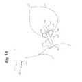
- FIG. 5Ais a schematic view of the device of FIG. 5 shown in situ, namely in a female urinary system;
- FIG. 6is a schematic view of a further embodiment of the flow control device of the subject invention shown in situ, namely in a male urinary system;
- FIG. 7is a schematic view of a device delivery apparatus, showing the device of FIG. 6 in a predeployment condition.
- FIG. 7Ais a view similar to that of FIG. 7 but instead showing the anchoring mechanism in an activated state.
- a urinary flow control device 10which generally includes an elongate member 12 having proximal 14 and distal 16 ends and a lumen 18 capable of discharging urine therethrough, and a flow control assembly 20 , operatively joined to the elongate member 12 , having first 22 and second 24 fluid containing compartments adapted to be in fluid communication with each other.
- the flow control assembly 20which is generally adapted to receive and contain urine from the bladder so as to impinge upon the first fluid containing compartment 22 , is designed to be responsive to increased bladder pressure such that fluid is displaced from the first fluid containing compartment 22 to the second fluid containing compartment 24 . Such responsiveness permits the select passage of urine from the bladder to the lumen 18 of the elongate member 12 for discharge into and through the urethra.
- the urinary flow control device of the subject inventionis secured in the male with an end (i.e., the “proximal” end) of the device positioned such that it is within the portion of the urethra that is commonly referred to as the bladder neck. So positioned, the device extends past the urethral sphincter(s) with its distal end terminating in the bulbous urethra. In the female anatomy, the proximal end of the device is also preferably positioned such that it is within the bladder neck. The device is positioned such that the distal end terminates exterior the meatus. While the encasements of the male and female devices may differ (e.g., see FIGS. 5 and 5A, and FIG. 6 ), common operational premises, and structures, underlay each.
- the urinary flow control device 10generally has static (e.g., FIGS. 1 and 2) and dynamic (e.g., FIGS. 3, 4 , and 4 A) configurations which correspond to urine “blocking” and urine “draining” conditions, each condition, and thereby device configuration, being responsive to physiologic conditions of the bladder.
- the flow control assembly 20blocks urine from entering the lumen 18 of the elongate member 12 , while in a dynamic configuration, whether it be initiated voluntarily (i.e., intentional as by manual manipulation of the device) or non-voluntarily (i.e., by discrete pressure impulse transmitted by the bladder, as by coughing, laughter, etc.), the flow control assembly 20 permits regulated urine drainage from the bladder to the urethra.
- FIGS. 1 and 2wherein there is shown the device 10 of the subject invention indwelling with respect to a male bladder 11 .
- the device 10shows a static configuration (i.e., closed or urine blocking position), namely the internal components thereof cooperatively arranged and engaged so as to prohibit urine from passing from the bladder 11 to the urethra 13 .
- the flow control assembly 20which includes first 22 and second 24 fluid containing compartments, is operatively joined to the elongated member 12 .
- Such operative connectionmay be made directly, as by the direct union of the flow control assembly 20 to the elongate member 12 (e.g., by joining select elements of the flow control assembly 20 , for instance the first fluid containing compartment 22 , or structures associated therewith, to the elongate member 12 ), or indirectly joining the assembly 20 to the elongate member 12 as by a casing 26 , or the like, as is illustrated and will be further detailed.
- the first fluid containing compartment 22is substantially defined by a minimally rigid component 28 from which a resilient dome-like membrane 30 extends.
- the casing 26which appears as a cylinder or sleeve, is generally shown directly joining a portion of the elongate member 12 (i.e., exterior proximal end) to a portion of the flow control assembly 20 , more particularly, the minimally rigid member 28 of the first fluid containing compartment 22 ).
- a cap 32which is generally attached to the flow control assembly 20 (i.e., to the rigid base 28 of the first fluid containing compartment 22 ), defines a proximal end for the device 10 , and more particularly as shown, delimits the proximal extent of the first fluid containing compartment 22 .
- the cap 32may alternately and suitable be joined to, or be integral with the casing 26 , or may otherwise be suitably arranged or even omitted as the case may be (e.g., where the rigid component 28 has a closed end, as opposed to a sleeve-like configuration as shown in the figures).
- the casing 26is generally adapted to receive urine from the bladder, as for instance by a series of radially spaced portals 34 , such that the first fluid containing compartment 22 , vis-a-vis the membrane 30 , may be responsive to bladder pressure.
- In-flowing urinewill generally occupy a void space 36 bounded by a sealing element 38 (i.e., ring), the casing 34 , and the flow control assembly 20 (i.e., first fluid containing compartment 22 ) for containment therein.
- the sealing element 38is disposed so as to seal the proximal end of the lumen 18 from the flow control assembly 20 , more particularly, the resilient membrane 30 of the first fluid containing compartment 22 sealingly engages the sealing element 38 to prohibit entry of urine into the lumen 18 .
- the sealing element 38may be integral to the exterior surface or skin 40 of the elongate member 12 , as shown, or a discrete structure positioned with respect to the proximal end of the elongate member 12 and the casing 26 so as abut the dome-like element 30 .
- the dome 30is of a specific geometry (e.g., semihemispherical) and material (e.g., low durometer silicone), the two properties being interrelated (i.e., jointly defining the performance character of the dome or membrane), so as to reversibly deform under specific pressure conditions (i.e., be pressure responsive), and thereby prohibit or permit, as the case may be, passage of urine from the bladder to the urethra.
- the material from which the dome is constructedpreferably has an inherent memory. This is evident functionally as the dome initially collapses at high pressure and subsequently restores to its original shape at a lower pressure. This attribute, in combination with the latching sequence, enables the device to be maintained in an, dynamic configuration until urine within bladder has returned to a relative low or no pressure state.
- the fluid containing compartments 22 , 24are linked by primary 42 and secondary 44 fluid passages or paths.
- the primary fluid passage 42is capable of selective passage of fluid between the fluid compartments in furtherance of passing urine from the bladder to the urethra.
- a conduit body 46generally traverses the first fluid containing compartment 22 and supports a conduit 48 which extends distally (i.e., toward the elongate member 12 ) from a proximal surface 50 thereof.
- the conduit 48is distally supported or positioned with respect to the membrane 30 by a collar-like element 52 which surrounds the conduit 48 and effectively defines an interface for the fluid containing compartments.
- the distal end of the conduit 48is shown within the second fluid containing compartment 24 .
- a latch mechanism 54in the form of a magnet, is positioned to prevent or prohibit inadvertent access of fluid from the first fluid compartment 22 to the second fluid compartment 24 via the primary passage 42 .
- the latch 54generally occupies the cavity 55 defined by the conduit body 46 , rigid first fluid containing member 28 , and the end cap 32 .
- the magnet 54is maintained in a “latched” condition against the proximal opening of the primary fluid passage 42 to prohibit fluid flow between the fluid compartments, preferably indirectly via a further sealing element or sealing surface 56 , by a second magnetic surface 58 contained within the conduit housing 46 .
- the latch 54(i.e., magnet) has a centering collar 60 located about the outer perimeter thereof to properly align it with the primary fluid passage 42 for sealing engagement therewith.
- the magnet 54is preferably comprised of a high flux density magnetic Neodymium 27 material. The small size of the magnet provides for a very long actuation distance with only a small external magnet. Magnet 54 is cylindrical in shape, preferable dimensioned to be about 0.125 inches in diameter by about 0.250 inches long, however, the actuation distance is dependent on the external magnet size and magnetic flux density, with actuation distances in excess of 9 centimeters easily accomplished with a small external activation magnet 62 . Magnet 54 is preferably coated with epoxy, paraxylene, or other substance known to eliminate or at least reduce the production of magnetic particulate, and thereby the known problems associated therewith.
- the secondary fluid passage 44extends through the collar-like element 52 which, as previously noted, generally positions the conduit 48 of the primary fluid passage 42 relative to the membrane 30 , and otherwise separates the first fluid compartment 22 from the second fluid compartment 24 .
- the secondary passage 44which allows fluid communication between the fluid containing compartments, is utilized in an over-pressure protection sequence (i.e., provides automatic pressure relief to the bladder by displacement of fluid from the first fluid containing compartment 22 to the second fluid containing compartment 24 ).
- the important consideration with respect to the over-pressure protection mechanismis that the secondary fluid containing compartment 24 be in fluid communication with the first fluid containing compartment 22 at all times so as to received displaced fluid therefrom, as during instances of increased or increasing bladder pressure, most notably those approaching or exceeding about 20 cm H 2 O for brief periods.
- the second fluid containing compartment 24is shown longitudinally extending within the lumen 18 of the elongate member 12 , though it need not be so positioned. Device size, performance, and manufacturing costs, to a great extent, determine the specific nature as well as the positioning of the second fluid containing compartment.
- the second fluid containing compartment 24which in effect functions as a reservoir for the first fluid containing compartment 22 , is preferably expansible or deformable, however, a more rigid or even fixed walled compartment may be suitable, and is within the scope of the present invention.
- the urinary flow control device 10is shown in a dynamic state, namely an externally initiated state.
- External or voluntary initiationoccurs when external magnet 62 is held approximately perpendicular to the at rest orientation of magnet 54 .
- Magnet 54is illustrated displaced slightly within cavity 55 . This displacement occurs because the poles of the magnet 54 are either attracted to, or repelled away from the approaching poles of the external magnet 62 .
- the initiated state occurring due to the north pole of magnet 54is illustrated attracted to the south pole of magnet 62 , however, pole orientation is not critical.
- the initiation mechanismfunctions nearly identically, whether by opposite poles attracting, or like poles repelling.
- fluidis in communication with the second fluid containing compartment 24 by the pathway illustrated by arrows 64 as a result of the primary fluid passage 42 being accessible to fluid by separation of the sealed interface between the distal extremity of magnet 54 and conduit body 46 .
- Fluidwill not be transferred along the passageway shown by arrows 64 until there is sufficient pressure within the bladder for urine to displace (i.e., collapse) the membrane 30 of the first fluid containing compartment 22 , thereby reversibly deflecting it away from ring seal 38 .
- Membrane 30in a static device configuration, blocks or seals passage into lumen 18 , whereas in a dynamic configuration for device 10 , membrane 30 permits passage into lumen 18 , in effect performing as a switching element.
- the deformable dome 30Prior to a sufficient volume of fluid being transferred into reservoir 24 , the deformable dome 30 remains in sealed contact with ring seal 38 .
- the passage of urine from the bladder to the elongate member 12 of urethral flow apparatus 10only occurs when the deformable dome 30 has been forced away from sealing ring 38 .
- the magnetic initiation sequenceopens or restricts the fluid pathway illustrated by arrows 64 when the magnet 62 is respectively introduced and removed from the region external the body which is roughly perpendicular of the urethral flow apparatus 10 .
- Second fluid containing compartment 24is illustrated in a filled or dilated state due to being “filled” with the fluid previously retained within the first fluid containing compartment 22 prior to the initiation sequence.
- the fluid passing between the compartmentsmay be locked into the reservoir 24 by removing magnet 62 at any time in the urination cycle, which allows for complete emptying of the bladder of urine effortlessly by the user.
- the urineflows through the pathway illustrated by arrows 65 into the lumen 18 of the elongate member 12 of flow control apparatus 10 , and subsequently exits the body.
- Closure of the flow control apparatus 10is accomplished by re-introduction of magnet 62 as previously explained.
- magnet 62When magnet 62 is held at an effective location for a short time, the shape memory of the deformable dome 30 draws fluid in a direction reverse of flow arrows 64 , and a sealable contact is re-established between the deformable dome 30 and sealing ring 38 . Magnet 62 is then removed until the next urination event is sensed.
- magnet 54is sealably stable (i.e., latched) against the sealing surface 56 and conduit body 46 . Fluid is thereby restricted from being moved from the first fluid containing compartment 22 through the primary fluid pathway 42 , illustrated by the arrows 64 of FIG. 3) into adjacent reservoir 24 . The only passage of fluid into reservoir 24 that can occur is through the secondary fluid passage 44 as illustrated by arrow 64 . In this condition, the internal fluid system (i.e., the fluid containing compartments 22 , 24 ) would normally be hydraulically locked, except for the over-pressure protection circuit which is incorporated into this device.
- the pressure of the impinging urineexceeds the design specific pressure required to displace the deformable dome 30 (i.e., preferably in the range of about 25 to 40 cm H 2 O) from contact with the sealing ring 38 , the fluid is forced through the secondary fluid passage 44 into the reservoir 24 .
- the deformable dome 30marginally collapses so as to yield a small separation 68 between the deformable dome 30 and sealing ring 38 .
- a small flow rate of urinewill then enter the lumen 18 and into the urethra.
- Secondary fluid passage 44is dimensionally sized so that the release of urine into the lumen 18 will not occur until pressure within the bladder exceeds approximately 30 cm H 2 O for a time longer than approximately 2 to 6 minutes. This rate of passage of fluid into reservoir 24 is viewed by clinicians to be safely within the parameters necessary to allow for protection of the renal tract.
- the internal geometryis selected to provide a balance between the pressure event duration and rate of passage opening, such that the device in effect may distinguish between the character of the over pressurization event, namely a discrete event such as coughing or straining on the one hand, and a more critical “unhealthy” chronic pressure increase or build up.
- the secondary fluid passageis approximately 0.004 inches in diameter, hydraulic diameter equivalent, and in excess of about 0.075 inches in length.
- Passage 44is preferably constructed by forming the silicone material with which conduit body 46 is constructed so as to produce such passage, as for instance by placement of a mandrel within the curing silicone, and removing same upon full cure, thereby leaving fluid passage 44 in tact.
- the fluid of the fluid elementpreferably has a viscosity of approximately 100 centipoise. It would be obvious to those skilled in fluid mechanics that changes in flow control assembly dimensions particulars (e.g., geometry, dimensions, materials of construction) directly effect the character (i.e., physical properties) of the fluid, and that numerous combinations can produce similarly desirable time delays for handling discrete bladder pressure impulses that typically are minimal.
- urethral flow control device 10will function as a pressure actuated flow control apparatus. The conditions that determine the threshold of actuation are then regulated by the mechanical characteristics of the deformable dome 30 , and the interior dimensions of conduit 48 , or alternatively the secondary fluid passage 44 . Such alterations of the device of the subject invention are contemplated for the treatment of urinary incontinence.
- the device 110generally includes an elongate member 112 having proximal 114 and distal 116 ends in a lumen 118 capable of discharging there through, and a flow control assembly 120 , operatively joined to the elongate member 112 , having first 122 and second 124 fluid containing compartments adapted to be in fluid communication with each other.
- Elongate member 112 and flow control assembly 120are operatively and structurally similar to the device heretofore discussed.
- a fluid “bulb” 170is co-axially encompassing elongate member 112 for “travel” (i.e., variable positioning) with respect thereto.
- Bulb 170is formed along the length of elongate member 112 by the anatomically responsive distribution of a physiologically inert fluid captured or sealed between an exterior surface 140 of elongate member 112 and a fluid containing layer 172 thereover.
- Bulb 170terminates at the distal extremity of the elongate member 112 at a meatal pad 174 .
- Bulb 170terminates at the proximal extremity at a bulb-casing termination 176 (i.e., the interface of layer 172 with casing 126 ).
- the meatal pad 174When device 110 is inserted for use, the meatal pad 174 is generally in contact with the meatus 178 of the urethra, with bulb 170 positioned within the bladder. As shown in FIG. 5, bulb 170 is in a first static state (i.e., a pre-deployment condition), with the fluid oriented near the distal extremity of the device 110 .
- FIG. 5Aillustrates bulb 170 being formed so as to be within the bladder, more particularly near the bladder neck, this orientation being a second stable state, namely, an anchoring configuration. The fluid will remain in this position until the urethral flow control device 110 is slowly and gently withdrawn.
- the pressure of the urethra and the underlying sphincterwill restrain the fluid from returning to the distal extremity under normal conditions thus restricting the urethral flow control device 110 from being expelled.
- pressure on urine impinges upon urethral flow apparatus 110slight movement in the distal direction may occur. If this does, bulb 170 interferes with the movement by increasing the contact pressure against the bladder neck (i.e., reacts in a wedge-like manner).
- Meatal pad 174provides for a comfortable limiter to prohibit movement of urethral flow control device 110 toward the bladder by spanning the meatus 178 .
- urinary flow control device 210is illustrated indwelling in the male urethra. This device operates to release urine in the identical manner as the prior embodiments. Sought after flow control functions are provided by flow control assembly 220 which is mounted on the proximal extremity of the device body. This embodiment provides for an alternative positioning and anchoring mechanism. Adjacent the flow control assembly 220 , proximal balloon 282 is in a filled condition, resting adjacent bladder base 284 near internal sphincter 286 .
- the device bodyextends through the interior of bladder base 284 , through the urethra in the regions of the internal sphincter 286 , prostate 288 , external sphincter 290 , and terminates within interior of the bulbous urethra.
- a distal balloon 292is located at the distal extremity of device body such that, in use, distal balloon 292 dwells in the bulbous urethra (i.e., occupies a portion thereof to aid device positioning and retention).
- the function of proximal balloon 282 , and distal balloon 292are to restrict the flow control apparatus 210 from moving either towards the bladder, or distally into the urethra.
- Tether 294provides for ease of removal of flow control apparatus 210 .
- FIGS. 7 and 7Aflow control apparatus 210 is illustrated on an insertion device 296 .
- FIG. 7illustrates flow control apparatus 210 without fluid in balloons 282 and 292 .
- Insertion device 296enables the insertion and securing of device 210 into the urethra and bladder without visualization as may be provided by x-ray, cystoscopy or ultrasound.
- the features and method of insertion and removal of urethral device 210are in part the subject matter of co-pending U.S. patent application No. 60/223,345, “LOWER URINARY TRACT FLOW CONTROL APPARATUS AND METHOD OF USE THEREOF”; Ser. No.
- Medical grade silicone to dateis the preferred urine contact material for urological products, which are indwelling within the urethra, bladder or meatal regions due to the relative inertness of this material in cooperation with urinary tract infections. All of the contact surfaces are medical grade silicone.
- the sealing methodologyinvolves a silicone deformable dome which, due to the repeated change in shape at every voiding, is only minimally susceptible to interruption of service due to encrustation.
- the silicone sealing ringis also soft and compliant.
- the flow control assemblymore particularly the fluid containing compartments, is configured to prohibit urine entry.
- the magnetic switchis hermetically sealed from contact with urine.
- the minimal pressures available for actuation of the devicefurther requires that the fluid is mostly void of air in order for the devices to provide sufficient flow rates (>9 cc/second).
- the devices which have been used clinically to datehave been provided with a slight internal vacuum of approximately 5 cm H 2 O.
- the fluid utilizedis selected according to the viscosity and biocompatibility.
- the current fluid utilizedis a low viscosity silicone fluid.
- Alternative fluidsmay be utilized such as olive oil, or other fluids which meet the viscosity requirements and which are preferably hydrophobic and relatively inert to the silicone or other material of the deformable dome and surrounding components.
- Similar materialssuch as medical grade silicones enhanced with anti-microbial elements such as polyethylene glycol, silver, silver ions, or alloys may be utilized to alter the physiological interaction with the urinary tract and urine.
- Other antibioticsmay further be compounded within the silicone or other elastomers to provide similar mechanical functions while delaying the onset of device corrosion or encrustation. It would be apparent to those skilled in the art that the configurations and parameters may be varied slightly to accomplish similar functions without deviating from the scope and intent of this invention.
Landscapes
- Health & Medical Sciences (AREA)
- Urology & Nephrology (AREA)
- Cardiology (AREA)
- Oral & Maxillofacial Surgery (AREA)
- Transplantation (AREA)
- Engineering & Computer Science (AREA)
- Biomedical Technology (AREA)
- Heart & Thoracic Surgery (AREA)
- Vascular Medicine (AREA)
- Life Sciences & Earth Sciences (AREA)
- Animal Behavior & Ethology (AREA)
- General Health & Medical Sciences (AREA)
- Public Health (AREA)
- Veterinary Medicine (AREA)
- External Artificial Organs (AREA)
- Orthopedics, Nursing, And Contraception (AREA)
- Prostheses (AREA)
Abstract
Description
Claims (36)
Priority Applications (3)
| Application Number | Priority Date | Filing Date | Title |
|---|---|---|---|
| US09/772,088US6527702B2 (en) | 2000-02-01 | 2001-01-26 | Urinary flow control device and method |
| US10/379,067US7001327B2 (en) | 2000-02-01 | 2003-03-04 | Urinary flow control device and method |
| US11/358,598US7803106B2 (en) | 2000-02-01 | 2006-02-21 | Urinary flow control device and method |
Applications Claiming Priority (2)
| Application Number | Priority Date | Filing Date | Title |
|---|---|---|---|
| US17903800P | 2000-02-01 | 2000-02-01 | |
| US09/772,088US6527702B2 (en) | 2000-02-01 | 2001-01-26 | Urinary flow control device and method |
Related Child Applications (1)
| Application Number | Title | Priority Date | Filing Date |
|---|---|---|---|
| US10/379,067ContinuationUS7001327B2 (en) | 2000-02-01 | 2003-03-04 | Urinary flow control device and method |
Publications (2)
| Publication Number | Publication Date |
|---|---|
| US20010034470A1 US20010034470A1 (en) | 2001-10-25 |
| US6527702B2true US6527702B2 (en) | 2003-03-04 |
Family
ID=26874932
Family Applications (3)
| Application Number | Title | Priority Date | Filing Date |
|---|---|---|---|
| US09/772,088Expired - LifetimeUS6527702B2 (en) | 2000-02-01 | 2001-01-26 | Urinary flow control device and method |
| US10/379,067Expired - LifetimeUS7001327B2 (en) | 2000-02-01 | 2003-03-04 | Urinary flow control device and method |
| US11/358,598Expired - LifetimeUS7803106B2 (en) | 2000-02-01 | 2006-02-21 | Urinary flow control device and method |
Family Applications After (2)
| Application Number | Title | Priority Date | Filing Date |
|---|---|---|---|
| US10/379,067Expired - LifetimeUS7001327B2 (en) | 2000-02-01 | 2003-03-04 | Urinary flow control device and method |
| US11/358,598Expired - LifetimeUS7803106B2 (en) | 2000-02-01 | 2006-02-21 | Urinary flow control device and method |
Country Status (1)
| Country | Link |
|---|---|
| US (3) | US6527702B2 (en) |
Cited By (79)
| Publication number | Priority date | Publication date | Assignee | Title |
|---|---|---|---|---|
| US20020107540A1 (en)* | 2001-01-23 | 2002-08-08 | Whalen Mark J. | Endourethral device & method |
| US20030078467A1 (en)* | 2001-10-18 | 2003-04-24 | Whalen Mark J. | Endourethral device & method |
| US20030153807A1 (en)* | 2000-02-01 | 2003-08-14 | Abbeymoor Medical, Inc. | Urinary flow control device & method |
| US20030208183A1 (en)* | 2000-08-07 | 2003-11-06 | Whalen Mark J. | Endourethral device & method |
| US20040015155A1 (en)* | 1999-12-01 | 2004-01-22 | Abbeymoor Medical, Inc. | Magnetic retrieval device and method of use |
| US20050059929A1 (en)* | 2003-09-17 | 2005-03-17 | Magnus Bolmsjo | Partial-length, indwelling prostatic catheter using coiled inflation tube as an anchor and methods of draining urine and flushing clots |
| US20050066331A1 (en)* | 2003-09-19 | 2005-03-24 | Shuji Inoue | Dynamic resource management for distributed retrieval system for security |
| US20050107721A1 (en)* | 2000-08-31 | 2005-05-19 | Abbeymoor Medical, Inc. | Diagnostic urethral assembly & method |
| US20050107735A1 (en)* | 1998-10-15 | 2005-05-19 | Scimed Life Systems, Inc. | Treating urinary retention |
| US20050148999A1 (en)* | 2003-12-30 | 2005-07-07 | Opmi Funding, Inc. | Continuous drainage adaptor |
| US20060111691A1 (en)* | 2003-09-17 | 2006-05-25 | Magnus Bolmsjo | Partial-length indwelling urinary catheter and method permitting selective urine discharge |
| US20060195009A1 (en)* | 2004-12-06 | 2006-08-31 | Sam Drager | Apparatus and method for correcting urinary incontinence |
| US20070049929A1 (en)* | 2005-05-20 | 2007-03-01 | Catanese Joseph Iii | Apparatus and method for manipulating or retracting tissue and anatomical structure |
| US20070276342A1 (en)* | 2006-03-28 | 2007-11-29 | Bryant Lin | Devices and related methods for treating incontinence |
| US20080039894A1 (en)* | 2005-05-20 | 2008-02-14 | Neotract, Inc. | Devices, systems and methods for retracting, lifting, compressing, supporting or repositioning tissues or anatomical structures |
| US20080097496A1 (en)* | 2006-10-20 | 2008-04-24 | Arvin Chang | System and method for securing an implantable interface to a mammal |
| US20080097487A1 (en)* | 2006-10-20 | 2008-04-24 | Scott Pool | Method and apparatus for adjusting a gastrointestinal restriction device |
| US20090018553A1 (en)* | 2007-07-09 | 2009-01-15 | Neotract, Inc. | Multi-actuating trigger anchor delivery system |
| US7758594B2 (en) | 2005-05-20 | 2010-07-20 | Neotract, Inc. | Devices, systems and methods for treating benign prostatic hyperplasia and other conditions |
| US20110040312A1 (en)* | 2005-05-20 | 2011-02-17 | Neotract, Inc. | Deforming anchor device |
| US7909836B2 (en) | 2005-05-20 | 2011-03-22 | Neotract, Inc. | Multi-actuating trigger anchor delivery system |
| US8157815B2 (en) | 2005-05-20 | 2012-04-17 | Neotract, Inc. | Integrated handle assembly for anchor delivery system |
| US20120130164A1 (en)* | 2010-11-24 | 2012-05-24 | Mount Sinai School Of Medicine | Magnetic based device for retrieving a misplaced article |
| US8216254B2 (en) | 2005-05-20 | 2012-07-10 | Neotract, Inc. | Anchor delivery system with replaceable cartridge |
| EP2477207A2 (en) | 2004-09-24 | 2012-07-18 | Zond, Inc. | Apparatus for generating high-current electrical discharges |
| US20120203210A1 (en)* | 2011-02-07 | 2012-08-09 | Schanz Richard W | Urinary catheter and method |
| US8333776B2 (en) | 2005-05-20 | 2012-12-18 | Neotract, Inc. | Anchor delivery system |
| US8394113B2 (en) | 2005-05-20 | 2013-03-12 | Neotract, Inc. | Coiled anchor device |
| US8425535B2 (en) | 2005-05-20 | 2013-04-23 | Neotract, Inc. | Multi-actuating trigger anchor delivery system |
| US8454655B2 (en) | 2002-03-14 | 2013-06-04 | Neotract, Inc. | Method for anchoring suture and approximating tissue |
| US8491606B2 (en) | 2005-05-20 | 2013-07-23 | Neotract, Inc. | Median lobe retraction apparatus and method |
| US8529584B2 (en) | 2005-05-20 | 2013-09-10 | Neotract, Inc. | Median lobe band implant apparatus and method |
| US8603106B2 (en) | 2005-05-20 | 2013-12-10 | Neotract, Inc. | Integrated handle assembly for anchor delivery system |
| US8628542B2 (en) | 2005-05-20 | 2014-01-14 | Neotract, Inc. | Median lobe destruction apparatus and method |
| US8668705B2 (en) | 2005-05-20 | 2014-03-11 | Neotract, Inc. | Latching anchor device |
| WO2014113595A1 (en)* | 2013-01-16 | 2014-07-24 | Mcdaniel Michael R | Pressure controlled magnetic valve for a catheter |
| US8790290B2 (en) | 2007-06-20 | 2014-07-29 | Covidien Lp | Gastric restrictor assembly and method of use |
| US8834492B2 (en) | 2005-05-20 | 2014-09-16 | Neotract, Inc. | Continuous indentation lateral lobe apparatus and method |
| US8945152B2 (en) | 2005-05-20 | 2015-02-03 | Neotract, Inc. | Multi-actuating trigger anchor delivery system |
| US9034001B2 (en) | 2005-05-20 | 2015-05-19 | Neotract, Inc. | Slotted anchor device |
| US9161749B2 (en) | 2011-04-14 | 2015-10-20 | Neotract, Inc. | Method and apparatus for treating sexual dysfunction |
| US9198755B2 (en) | 2008-03-25 | 2015-12-01 | Ellipse Technologies, Inc. | Adjustable implant system |
| US9364212B2 (en) | 2005-05-20 | 2016-06-14 | Neotract, Inc. | Suture anchoring devices and methods for use |
| US9504461B2 (en) | 2005-05-20 | 2016-11-29 | Neotract, Inc. | Anchor delivery system |
| US9549739B2 (en) | 2005-05-20 | 2017-01-24 | Neotract, Inc. | Devices, systems and methods for treating benign prostatic hyperplasia and other conditions |
| WO2017017688A2 (en) | 2015-07-29 | 2017-02-02 | The Trendlines Group Ltd. | Method and device for treatment of stress urinary incontinence (sui) |
| US9775698B2 (en) | 2015-01-23 | 2017-10-03 | Spinal Singularity, Inc. | Urinary prosthesis systems |
| US10016220B2 (en) | 2011-11-01 | 2018-07-10 | Nuvasive Specialized Orthopedics, Inc. | Adjustable magnetic devices and methods of using same |
| US10130353B2 (en) | 2012-06-29 | 2018-11-20 | Neotract, Inc. | Flexible system for delivering an anchor |
| US10195014B2 (en) | 2005-05-20 | 2019-02-05 | Neotract, Inc. | Devices, systems and methods for treating benign prostatic hyperplasia and other conditions |
| US10238427B2 (en) | 2015-02-19 | 2019-03-26 | Nuvasive Specialized Orthopedics, Inc. | Systems and methods for vertebral adjustment |
| US10271885B2 (en) | 2014-12-26 | 2019-04-30 | Nuvasive Specialized Orthopedics, Inc. | Systems and methods for distraction |
| US10292801B2 (en) | 2012-03-29 | 2019-05-21 | Neotract, Inc. | System for delivering anchors for treating incontinence |
| US10349995B2 (en) | 2007-10-30 | 2019-07-16 | Nuvasive Specialized Orthopedics, Inc. | Skeletal manipulation method |
| US10405891B2 (en) | 2010-08-09 | 2019-09-10 | Nuvasive Specialized Orthopedics, Inc. | Maintenance feature in magnetic implant |
| US10478232B2 (en) | 2009-04-29 | 2019-11-19 | Nuvasive Specialized Orthopedics, Inc. | Interspinous process device and method |
| US10517643B2 (en) | 2009-02-23 | 2019-12-31 | Nuvasive Specialized Orthopedics, Inc. | Non-invasive adjustable distraction system |
| US10617453B2 (en) | 2015-10-16 | 2020-04-14 | Nuvasive Specialized Orthopedics, Inc. | Adjustable devices for treating arthritis of the knee |
| US10646262B2 (en) | 2011-02-14 | 2020-05-12 | Nuvasive Specialized Orthopedics, Inc. | System and method for altering rotational alignment of bone sections |
| US10660675B2 (en) | 2010-06-30 | 2020-05-26 | Nuvasive Specialized Orthopedics, Inc. | External adjustment device for distraction device |
| US10675435B2 (en) | 2015-04-01 | 2020-06-09 | Spinal Singularity, Inc. | Extended-use valved urinary catheter |
| US10729470B2 (en) | 2008-11-10 | 2020-08-04 | Nuvasive Specialized Orthopedics, Inc. | External adjustment device for distraction device |
| US10743794B2 (en) | 2011-10-04 | 2020-08-18 | Nuvasive Specialized Orthopedics, Inc. | Devices and methods for non-invasive implant length sensing |
| US10751094B2 (en) | 2013-10-10 | 2020-08-25 | Nuvasive Specialized Orthopedics, Inc. | Adjustable spinal implant |
| US10751506B2 (en) | 2015-04-01 | 2020-08-25 | Spinal Singularity, Inc. | Catheters and catheter mating devices and systems |
| US10835290B2 (en) | 2015-12-10 | 2020-11-17 | Nuvasive Specialized Orthopedics, Inc. | External adjustment device for distraction device |
| US10918425B2 (en) | 2016-01-28 | 2021-02-16 | Nuvasive Specialized Orthopedics, Inc. | System and methods for bone transport |
| US10925587B2 (en) | 2005-05-20 | 2021-02-23 | Neotract, Inc. | Anchor delivery system |
| US11065093B2 (en) | 2015-01-23 | 2021-07-20 | Spinal Singularity, Inc. | Catheter mating devices |
| US11191579B2 (en) | 2012-10-29 | 2021-12-07 | Nuvasive Specialized Orthopedics, Inc. | Adjustable devices for treating arthritis of the knee |
| US11202707B2 (en) | 2008-03-25 | 2021-12-21 | Nuvasive Specialized Orthopedics, Inc. | Adjustable implant system |
| US11246694B2 (en) | 2014-04-28 | 2022-02-15 | Nuvasive Specialized Orthopedics, Inc. | System for informational magnetic feedback in adjustable implants |
| US11298115B2 (en) | 2020-08-03 | 2022-04-12 | Teleflex Life Sciences Limited | Handle and cartridge system for medical interventions |
| US11357549B2 (en) | 2004-07-02 | 2022-06-14 | Nuvasive Specialized Orthopedics, Inc. | Expandable rod system to treat scoliosis and method of using the same |
| US11510765B2 (en) | 2015-01-23 | 2022-11-29 | Spinal Singularity, Inc. | Extended-use catheters |
| US11628271B2 (en) | 2019-06-10 | 2023-04-18 | Spinal Singularity, Inc. | Urinary catheter |
| US11672520B2 (en) | 2017-12-23 | 2023-06-13 | Teleflex Life Sciences Limited | Expandable tissue engagement apparatus and method |
| US11865270B2 (en) | 2020-01-16 | 2024-01-09 | Starling Medical, Inc. | Bodily fluid management system |
| US12440301B2 (en) | 2019-10-30 | 2025-10-14 | Teleflex Life Sciences Llc | System for delivery of a fiducial marker |
Families Citing this family (14)
| Publication number | Priority date | Publication date | Assignee | Title |
|---|---|---|---|---|
| US6949125B2 (en)* | 2002-04-16 | 2005-09-27 | Boston Scientific Scimed, Inc. | Ureteral stent with end-effector and related methods |
| US7691053B2 (en) | 2005-05-20 | 2010-04-06 | Tyco Healthcare Group Lp | Gastric restrictor assembly and method of use |
| US7666180B2 (en) | 2005-05-20 | 2010-02-23 | Tyco Healthcare Group Lp | Gastric restrictor assembly and method of use |
| NL1036388C2 (en)* | 2009-01-07 | 2010-07-08 | Applied Medical Developments B V | DEVICE SUITABLE FOR IMPLANTATION AT A DESIRED POSITION IN A LUMEN OF A HEAT-BLOODED LIFE AND A HOLDER SUITABLE FOR SUCH INVENTION. |
| US8801697B2 (en)* | 2009-04-20 | 2014-08-12 | Cheiron Japan Co. | Urination control device |
| GB2489712A (en)* | 2011-04-05 | 2012-10-10 | Mark Anthony Donbavand | Implantable urine flow control valves |
| WO2013075723A1 (en)* | 2011-11-23 | 2013-05-30 | Magcath Aps | Incontinence device |
| EP3049019A1 (en)* | 2013-09-25 | 2016-08-03 | Medtronic, Inc. | Implantable urinary tract valve |
| DK178335B1 (en)* | 2014-05-28 | 2015-12-21 | Magcath Aps | A urine flow control system and a magnetic actuator device |
| WO2015180730A1 (en)* | 2014-05-28 | 2015-12-03 | Magcath Aps | A urine flow control system and a magnetic actuator device |
| US11957851B2 (en) | 2017-04-10 | 2024-04-16 | Flat Medical Inc. | Catheter for guiding body fluid |
| US10010392B1 (en) | 2017-09-06 | 2018-07-03 | Stanislaw L Zukowski | Indwelling valve actuated urinary catheter |
| GB2602834B (en)* | 2021-01-18 | 2023-04-26 | Grey Matter Designs Ltd | Improvements in or relating to fluid management systems |
| US11752302B1 (en) | 2022-11-28 | 2023-09-12 | Stanislaw Zukowski | Indwelling valve actuated urinary catheter |
Citations (79)
| Publication number | Priority date | Publication date | Assignee | Title |
|---|---|---|---|---|
| US2078686A (en) | 1935-07-29 | 1937-04-27 | Louis Janisky | Internal orifice thermal dilator and medicator |
| US2450217A (en) | 1944-11-16 | 1948-09-28 | Harvey A Alcorn | Teat draining tube |
| US2687131A (en) | 1952-09-17 | 1954-08-24 | Davol Rubber Co | Female incontinence catheter |
| US3136316A (en) | 1962-01-19 | 1964-06-09 | Abbott Lab | Catheter |
| US3495620A (en) | 1967-02-09 | 1970-02-17 | Weck & Co Inc Edward | Magnetic valve |
| US3630206A (en) | 1970-01-02 | 1971-12-28 | Bruce Gingold | Bladder catheter |
| US3642004A (en)* | 1970-01-05 | 1972-02-15 | Life Support Equipment Corp | Urethral valve |
| US3731670A (en) | 1971-05-03 | 1973-05-08 | David Roy Pressman | Corporeal fluid control using bistable magnetic duct valve |
| US3812841A (en)* | 1972-08-21 | 1974-05-28 | L Isaacson | Urethra magnetic valve structure |
| US3908637A (en) | 1974-04-22 | 1975-09-30 | Louis W Doroshow | Rigid urethral instrument |
| US4217911A (en) | 1978-10-27 | 1980-08-19 | The Kendall Company | Cystometry system |
| US4249536A (en) | 1979-05-14 | 1981-02-10 | Vega Roger E | Urological catheter |
| US4301811A (en) | 1978-10-27 | 1981-11-24 | The Kendall Company | Cystometry system |
| US4407301A (en) | 1981-01-27 | 1983-10-04 | C. R. Bard, Inc. | Disc membrane catheter for performing cystometrograms and urethral profiles |
| US4432757A (en) | 1980-05-09 | 1984-02-21 | Davis Jr Richard C | Indwelling urethral catheter |
| US4484585A (en) | 1981-09-12 | 1984-11-27 | Richard Wolf Gmbh | Catheters |
| US4500313A (en) | 1983-01-27 | 1985-02-19 | Protectair Limited | Urethral catheter |
| US4501580A (en) | 1980-12-12 | 1985-02-26 | Glassman Jacob A | Indwelling catheters |
| US4538621A (en) | 1983-01-25 | 1985-09-03 | Urotek Inc. | Urodynamic catheter |
| US4553959A (en) | 1982-01-27 | 1985-11-19 | The Victoria University Of Manchester | Urethral catheter |
| US4553533A (en) | 1983-11-08 | 1985-11-19 | Leighton Stephen B | Intra-urethral prosthetic sphincter valve |
| US4612939A (en) | 1984-10-15 | 1986-09-23 | Robertson Jack R | Method for diagnosis of stress incontinence in women |
| US4721095A (en) | 1983-09-14 | 1988-01-26 | Centre National De La Recherche Scientifique | Device for controlling the flow of a fluid and a prosthetic organ equipped with this device |
| US4737147A (en) | 1985-06-06 | 1988-04-12 | N.U.S. S.R.L. | Catheter provided with an additional canalization |
| US4781677A (en) | 1985-07-17 | 1988-11-01 | Wilcox Gilbert M | Method of treatment utilizing a double balloon nasobiliary occlusion catheter |
| US4792335A (en) | 1987-02-11 | 1988-12-20 | Goosen Carl C | Pressure controlled valve apparatus |
| US4865030A (en) | 1987-01-21 | 1989-09-12 | American Medical Systems, Inc. | Apparatus for removal of objects from body passages |
| US4865588A (en) | 1988-08-31 | 1989-09-12 | Medical Inventor's Corp. | Magnetic bladder cycler and use method |
| US4873990A (en) | 1988-09-23 | 1989-10-17 | The United States Of America As Represented By The Administrator Of The National Aeronautics And Space Administration | Circumferential pressure probe |
| US4909785A (en) | 1986-03-25 | 1990-03-20 | American Medical Systems, Inc. | Method for valving body fluids |
| US4932938A (en) | 1989-05-05 | 1990-06-12 | Medical Engineering Corporation | Urethral indwelling catheter with incontinence control |
| US4934999A (en) | 1987-07-28 | 1990-06-19 | Paul Bader | Closure for a male urethra |
| US4946449A (en) | 1986-12-18 | 1990-08-07 | Davis Jr Richard C | Indwelling urethral catheter system and method |
| US5030199A (en)* | 1989-12-11 | 1991-07-09 | Medical Engineering Corporation | Female incontinence control device with magnetically operable valve and method |
| US5041092A (en) | 1989-08-29 | 1991-08-20 | Medical Engineering Corporation | Urethral indwelling catheter with magnetically controlled drainage valve and method |
| US5059169A (en) | 1989-07-07 | 1991-10-22 | C. R. Bard, Inc. | High-friction prostatic stent |
| US5088980A (en) | 1990-05-31 | 1992-02-18 | The United States Of America As Represented By The Department Of Health And Human Services | Intra-urethral valve with integral spring |
| US5090424A (en) | 1990-12-31 | 1992-02-25 | Uromed Corporation | Conformable urethral plug |
| US5112306A (en) | 1986-03-25 | 1992-05-12 | American Medical Systems, Inc. | Method and apparatus for valving body fluids |
| US5114398A (en) | 1990-02-27 | 1992-05-19 | Medical Engineering Corporation | Female incontinence control device with mechanically operable valve |
| US5140999A (en)* | 1991-09-30 | 1992-08-25 | Primed International Corp. | Urinary incontinence valve device |
| US5234409A (en) | 1989-07-07 | 1993-08-10 | Cabot Technology Corporation | Female incontinence control device and method |
| US5250029A (en) | 1991-11-06 | 1993-10-05 | Edward Lin | Zero-residual zero-tip balloon catheter |
| US5271735A (en) | 1985-10-15 | 1993-12-21 | Albert R. Greenfeld | Exterior antimigration refinements for self-cleaning indwelling therapeutic articles |
| US5360402A (en) | 1990-01-10 | 1994-11-01 | Rochester Medical Corporation | Hand-actuated retention catheter |
| US5366506A (en) | 1993-04-05 | 1994-11-22 | Davis Phillip J | Proximity intraurethral valve using permanent magnet check |
| US5380268A (en) | 1993-06-07 | 1995-01-10 | Wheeler; Douglas E. | Body fluid flow control valve and method |
| US5385563A (en) | 1993-09-14 | 1995-01-31 | The Kendall Company | Urodynamic catheter |
| US5427115A (en) | 1993-09-13 | 1995-06-27 | Boston Scientific Corporation | Apparatus for stricture diagnosis and treatment |
| US5429620A (en) | 1994-08-03 | 1995-07-04 | Uroquest Corporation | Calibrated disconnect joint for urethral catheter |
| US5437604A (en) | 1993-12-23 | 1995-08-01 | Hk Medical Technologies, Incorporated | Nonsurgical intraurethral bladder control device |
| US5483976A (en)* | 1990-12-31 | 1996-01-16 | Uromed Corporation | Mechanically actuated urethral plug assembly and method for controlling urinary incontinence |
| US5527336A (en) | 1986-12-09 | 1996-06-18 | Boston Scientific Corporation | Flow obstruction treatment method |
| US5711314A (en)* | 1996-11-08 | 1998-01-27 | Primed International Corporation | Urinary incontinence valve with distal and proximal anchoring means |
| US5713877A (en)* | 1996-06-05 | 1998-02-03 | Urocath Corporation | Indwelling magnetically-actuated urinary catheter, and method of its construction |
| US5718686A (en) | 1996-07-02 | 1998-02-17 | Urocath Corporation | Anchoring system and method for indwelling urethral catheter |
| US5724994A (en)* | 1990-12-31 | 1998-03-10 | Uromed Corporation | Fluidly expandable urethral plug assembly which receives fluid from an external source and method for controlling urinary incontinence |
| US5735831A (en) | 1996-07-10 | 1998-04-07 | Cordis Corporation | Expandable flowrate catheter assembly and method of making same |
| US5752525A (en)* | 1990-12-31 | 1998-05-19 | Uromed Corporation | Urethral plug assembly having adhesive for enhanced sealing capabilities and method of using said plug assembly |
| US5762599A (en)* | 1994-05-02 | 1998-06-09 | Influence Medical Technologies, Ltd. | Magnetically-coupled implantable medical devices |
| US5766209A (en) | 1993-02-19 | 1998-06-16 | Devonec; Marian A. | Prosthesis intended for the treatment of a natural lumen or tract, in particular an endo-urethral prosthesis |
| US5776081A (en) | 1995-06-06 | 1998-07-07 | University Of Iowa Research Foundation | Urethral pressure catheter |
| US5785641A (en) | 1996-05-08 | 1998-07-28 | Urocath Corporation | Male indwelling urethral catheter sizing system and insertion method |
| US5813974A (en)* | 1995-12-19 | 1998-09-29 | Dolade Guardia; Jose Manuel | Device for women suffering from incontinence |
| US5864961A (en) | 1996-09-04 | 1999-02-02 | Vaughan; Ward P. | Urethral probe for diagnosing stress incontinence |
| US5876417A (en) | 1995-07-10 | 1999-03-02 | Devonec; Marian | Detachable catheter apparatus |
| US5916195A (en) | 1998-02-04 | 1999-06-29 | Argomed Ltd. | Internal catheter |
| US5964732A (en) | 1997-02-07 | 1999-10-12 | Abbeymoor Medical, Inc. | Urethral apparatus with position indicator and methods of use thereof |
| US5971967A (en) | 1997-08-19 | 1999-10-26 | Abbeymoor Medical, Inc. | Urethral device with anchoring system |
| US5976068A (en)* | 1998-03-23 | 1999-11-02 | 3H Inc. | Female urinary incontinence device |
| US6022312A (en)* | 1995-05-05 | 2000-02-08 | Chaussy; Christian | Endosphincter, set for releasable closure of the urethra and method for introduction of an endosphincter into the urethra |
| US6033413A (en)* | 1998-04-20 | 2000-03-07 | Endocare, Inc. | Stent delivery system |
| WO2000021462A1 (en) | 1998-10-15 | 2000-04-20 | Scimed Life Systems, Inc. | Treating urinary retention |
| US6056699A (en) | 1996-05-05 | 2000-05-02 | Influence Medical Technologies Limited | Apparatus for the measurement of urethral angle change and vesical pressure |
| US6083179A (en) | 1996-05-20 | 2000-07-04 | Formo Medical Ab (Publ.) | Sensor to detect changes in the cross section of an elongated body cavity |
| US6105580A (en)* | 1994-11-03 | 2000-08-22 | Uroscientific, Incorporated | Urine control device |
| US6132365A (en)* | 1993-12-30 | 2000-10-17 | Sigurdsson; Per Arne | Valve |
| US6167886B1 (en)* | 1997-05-28 | 2001-01-02 | Medi-Globe Vertriebs Gmbh | Device for treatment of male and female urinary incontinence |
| US6234956B1 (en)* | 1999-08-11 | 2001-05-22 | Hongping He | Magnetic actuation urethral valve |
Family Cites Families (30)
| Publication number | Priority date | Publication date | Assignee | Title |
|---|---|---|---|---|
| US3706307A (en) | 1970-07-08 | 1972-12-19 | Hollister Inc | Gynecological instrument |
| US3742960A (en) | 1971-10-07 | 1973-07-03 | Kendall & Co | Deflatable retention catheter |
| US4121572A (en) | 1977-02-07 | 1978-10-24 | G.D. Searle & Co. | Uterine sound |
| US4489732A (en) | 1982-09-20 | 1984-12-25 | Hasson Harrith M | Gynecological instrument |
| US4784647A (en)* | 1986-07-30 | 1988-11-15 | The Kendal Company | Catheter meatal pad device |
| US4932958A (en) | 1988-05-10 | 1990-06-12 | American Medical Systems, Inc. | Prostate balloon dilator |
| US4968294A (en)* | 1989-02-09 | 1990-11-06 | Salama Fouad A | Urinary control valve and method of using same |
| IL89297A0 (en)* | 1989-02-15 | 1989-09-10 | Technion Res & Dev Foundation | Auxilary intra-urethral magnetic valve for persons suffering from urinary incontinence |
| US5071429A (en) | 1990-08-24 | 1991-12-10 | Medical Engineering Corporation | Method for inserting a balloon catheter through an endoscope |
| US5176626A (en) | 1992-01-15 | 1993-01-05 | Wilson-Cook Medical, Inc. | Indwelling stent |
| US5242398A (en) | 1992-03-12 | 1993-09-07 | Knoll Charles L | Catheter assembly and related method |
| US5295979A (en) | 1992-03-27 | 1994-03-22 | P & D Medical Coatings, Inc. | Urinary catheter and system |
| US5254089A (en) | 1992-04-02 | 1993-10-19 | Boston Scientific Corp. | Medication dispensing balloon catheter |
| US5322501A (en) | 1992-10-02 | 1994-06-21 | Mahmud Durrani Ayaz | Continent urethral stent for treating and preventing urethral stricture after surgery |
| US5320605A (en) | 1993-01-22 | 1994-06-14 | Harvinder Sahota | Multi-wire multi-balloon catheter |
| US5403280A (en) | 1993-02-16 | 1995-04-04 | Wang; James C. | Inflatable perfusion catheter |
| US5624374A (en)* | 1994-11-03 | 1997-04-29 | Von Iderstein; Irwin F. | Involuntary urine control apparatus, system and method |
| US5624395A (en)* | 1995-02-23 | 1997-04-29 | Cv Dynamics, Inc. | Urinary catheter having palpitatable valve and balloon and method for making same |
| US5701916A (en) | 1995-08-16 | 1997-12-30 | Hk Medical Technologies Incorporated | Intraurethral bladder control device with retainer apparatus |
| US5657764A (en) | 1995-08-30 | 1997-08-19 | Uromed Corporation | Device and method for determining the length of a urethra |
| US5609583A (en) | 1995-09-21 | 1997-03-11 | Hakki; A-Hamid I. | Collapsible catheter |
| US5713829A (en)* | 1996-07-08 | 1998-02-03 | Fuji Tsu Limited | Female urinary incontinence device |
| US6494848B1 (en) | 1996-12-19 | 2002-12-17 | St. Jude Medical Puerto Rico B.V. | Measuring device for use with a hemostatic puncture closure device |
| US6042535A (en)* | 1997-07-17 | 2000-03-28 | Srs Medical Systems, Inc. | Flow-around valve |
| US5884629A (en)* | 1998-05-22 | 1999-03-23 | O'brien; Christopher J. | Male urethral occlusive device |
| US6183413B1 (en)* | 1998-12-09 | 2001-02-06 | Hk Medical Technologies Incorporated | Valve for bladder control device |
| EP1120131A3 (en)* | 2000-01-27 | 2001-10-10 | Nihon Kohden Corporation | Electromagnetic coil apparatus for urinary incontinence treatment |
| US6527702B2 (en)* | 2000-02-01 | 2003-03-04 | Abbeymoor Medical, Inc. | Urinary flow control device and method |
| US6447462B1 (en) | 2000-02-15 | 2002-09-10 | Clinical Innovation Associates, Inc. | Urodynamic catheter and methods of fabrication and use |
| US6494855B2 (en) | 2001-05-16 | 2002-12-17 | Scimed Life Systems, Inc. | Draining bodily fluid |
- 2001
- 2001-01-26USUS09/772,088patent/US6527702B2/ennot_activeExpired - Lifetime
- 2003
- 2003-03-04USUS10/379,067patent/US7001327B2/ennot_activeExpired - Lifetime
- 2006
- 2006-02-21USUS11/358,598patent/US7803106B2/ennot_activeExpired - Lifetime
Patent Citations (81)
| Publication number | Priority date | Publication date | Assignee | Title |
|---|---|---|---|---|
| US2078686A (en) | 1935-07-29 | 1937-04-27 | Louis Janisky | Internal orifice thermal dilator and medicator |
| US2450217A (en) | 1944-11-16 | 1948-09-28 | Harvey A Alcorn | Teat draining tube |
| US2687131A (en) | 1952-09-17 | 1954-08-24 | Davol Rubber Co | Female incontinence catheter |
| US3136316A (en) | 1962-01-19 | 1964-06-09 | Abbott Lab | Catheter |
| US3495620A (en) | 1967-02-09 | 1970-02-17 | Weck & Co Inc Edward | Magnetic valve |
| US3630206A (en) | 1970-01-02 | 1971-12-28 | Bruce Gingold | Bladder catheter |
| US3642004A (en)* | 1970-01-05 | 1972-02-15 | Life Support Equipment Corp | Urethral valve |
| US3731670A (en) | 1971-05-03 | 1973-05-08 | David Roy Pressman | Corporeal fluid control using bistable magnetic duct valve |
| US3812841A (en)* | 1972-08-21 | 1974-05-28 | L Isaacson | Urethra magnetic valve structure |
| US3908637A (en) | 1974-04-22 | 1975-09-30 | Louis W Doroshow | Rigid urethral instrument |
| US4217911A (en) | 1978-10-27 | 1980-08-19 | The Kendall Company | Cystometry system |
| US4301811A (en) | 1978-10-27 | 1981-11-24 | The Kendall Company | Cystometry system |
| US4249536A (en) | 1979-05-14 | 1981-02-10 | Vega Roger E | Urological catheter |
| US4432757A (en) | 1980-05-09 | 1984-02-21 | Davis Jr Richard C | Indwelling urethral catheter |
| US4501580A (en) | 1980-12-12 | 1985-02-26 | Glassman Jacob A | Indwelling catheters |
| US4407301A (en) | 1981-01-27 | 1983-10-04 | C. R. Bard, Inc. | Disc membrane catheter for performing cystometrograms and urethral profiles |
| US4484585A (en) | 1981-09-12 | 1984-11-27 | Richard Wolf Gmbh | Catheters |
| US4553959A (en) | 1982-01-27 | 1985-11-19 | The Victoria University Of Manchester | Urethral catheter |
| US4538621A (en) | 1983-01-25 | 1985-09-03 | Urotek Inc. | Urodynamic catheter |
| US4500313A (en) | 1983-01-27 | 1985-02-19 | Protectair Limited | Urethral catheter |
| US4721095A (en) | 1983-09-14 | 1988-01-26 | Centre National De La Recherche Scientifique | Device for controlling the flow of a fluid and a prosthetic organ equipped with this device |
| US4553533A (en) | 1983-11-08 | 1985-11-19 | Leighton Stephen B | Intra-urethral prosthetic sphincter valve |
| US4612939A (en) | 1984-10-15 | 1986-09-23 | Robertson Jack R | Method for diagnosis of stress incontinence in women |
| US4737147A (en) | 1985-06-06 | 1988-04-12 | N.U.S. S.R.L. | Catheter provided with an additional canalization |
| US4781677A (en) | 1985-07-17 | 1988-11-01 | Wilcox Gilbert M | Method of treatment utilizing a double balloon nasobiliary occlusion catheter |
| US5271735A (en) | 1985-10-15 | 1993-12-21 | Albert R. Greenfeld | Exterior antimigration refinements for self-cleaning indwelling therapeutic articles |
| US5112306A (en) | 1986-03-25 | 1992-05-12 | American Medical Systems, Inc. | Method and apparatus for valving body fluids |
| US4909785A (en) | 1986-03-25 | 1990-03-20 | American Medical Systems, Inc. | Method for valving body fluids |
| US5527336A (en) | 1986-12-09 | 1996-06-18 | Boston Scientific Corporation | Flow obstruction treatment method |
| US4946449A (en) | 1986-12-18 | 1990-08-07 | Davis Jr Richard C | Indwelling urethral catheter system and method |
| US4865030A (en) | 1987-01-21 | 1989-09-12 | American Medical Systems, Inc. | Apparatus for removal of objects from body passages |
| US4792335A (en) | 1987-02-11 | 1988-12-20 | Goosen Carl C | Pressure controlled valve apparatus |
| US4934999A (en) | 1987-07-28 | 1990-06-19 | Paul Bader | Closure for a male urethra |
| US4865588A (en) | 1988-08-31 | 1989-09-12 | Medical Inventor's Corp. | Magnetic bladder cycler and use method |
| US4873990A (en) | 1988-09-23 | 1989-10-17 | The United States Of America As Represented By The Administrator Of The National Aeronautics And Space Administration | Circumferential pressure probe |
| US4932938A (en) | 1989-05-05 | 1990-06-12 | Medical Engineering Corporation | Urethral indwelling catheter with incontinence control |
| US5059169A (en) | 1989-07-07 | 1991-10-22 | C. R. Bard, Inc. | High-friction prostatic stent |
| US5234409A (en) | 1989-07-07 | 1993-08-10 | Cabot Technology Corporation | Female incontinence control device and method |
| US5041092A (en) | 1989-08-29 | 1991-08-20 | Medical Engineering Corporation | Urethral indwelling catheter with magnetically controlled drainage valve and method |
| US5030199A (en)* | 1989-12-11 | 1991-07-09 | Medical Engineering Corporation | Female incontinence control device with magnetically operable valve and method |
| US5360402A (en) | 1990-01-10 | 1994-11-01 | Rochester Medical Corporation | Hand-actuated retention catheter |
| US5114398A (en) | 1990-02-27 | 1992-05-19 | Medical Engineering Corporation | Female incontinence control device with mechanically operable valve |
| US5088980A (en) | 1990-05-31 | 1992-02-18 | The United States Of America As Represented By The Department Of Health And Human Services | Intra-urethral valve with integral spring |
| US5483976A (en)* | 1990-12-31 | 1996-01-16 | Uromed Corporation | Mechanically actuated urethral plug assembly and method for controlling urinary incontinence |
| US5090424A (en) | 1990-12-31 | 1992-02-25 | Uromed Corporation | Conformable urethral plug |
| US5724994A (en)* | 1990-12-31 | 1998-03-10 | Uromed Corporation | Fluidly expandable urethral plug assembly which receives fluid from an external source and method for controlling urinary incontinence |
| US5752525A (en)* | 1990-12-31 | 1998-05-19 | Uromed Corporation | Urethral plug assembly having adhesive for enhanced sealing capabilities and method of using said plug assembly |
| US5140999A (en)* | 1991-09-30 | 1992-08-25 | Primed International Corp. | Urinary incontinence valve device |
| US5250029A (en) | 1991-11-06 | 1993-10-05 | Edward Lin | Zero-residual zero-tip balloon catheter |
| US5766209A (en) | 1993-02-19 | 1998-06-16 | Devonec; Marian A. | Prosthesis intended for the treatment of a natural lumen or tract, in particular an endo-urethral prosthesis |
| US5366506A (en) | 1993-04-05 | 1994-11-22 | Davis Phillip J | Proximity intraurethral valve using permanent magnet check |
| US5380268A (en) | 1993-06-07 | 1995-01-10 | Wheeler; Douglas E. | Body fluid flow control valve and method |
| US5427115A (en) | 1993-09-13 | 1995-06-27 | Boston Scientific Corporation | Apparatus for stricture diagnosis and treatment |
| US5385563A (en) | 1993-09-14 | 1995-01-31 | The Kendall Company | Urodynamic catheter |
| US5437604A (en) | 1993-12-23 | 1995-08-01 | Hk Medical Technologies, Incorporated | Nonsurgical intraurethral bladder control device |
| US5512032A (en) | 1993-12-23 | 1996-04-30 | Hk Medical Technologies, Inc. | Nonsurgical intraurethral bladder control device |
| US6132365A (en)* | 1993-12-30 | 2000-10-17 | Sigurdsson; Per Arne | Valve |
| US5762599A (en)* | 1994-05-02 | 1998-06-09 | Influence Medical Technologies, Ltd. | Magnetically-coupled implantable medical devices |
| US5429620A (en) | 1994-08-03 | 1995-07-04 | Uroquest Corporation | Calibrated disconnect joint for urethral catheter |
| US6105580A (en)* | 1994-11-03 | 2000-08-22 | Uroscientific, Incorporated | Urine control device |
| US6022312A (en)* | 1995-05-05 | 2000-02-08 | Chaussy; Christian | Endosphincter, set for releasable closure of the urethra and method for introduction of an endosphincter into the urethra |
| US5776081A (en) | 1995-06-06 | 1998-07-07 | University Of Iowa Research Foundation | Urethral pressure catheter |
| US5876417A (en) | 1995-07-10 | 1999-03-02 | Devonec; Marian | Detachable catheter apparatus |
| US5813974A (en)* | 1995-12-19 | 1998-09-29 | Dolade Guardia; Jose Manuel | Device for women suffering from incontinence |
| US6056699A (en) | 1996-05-05 | 2000-05-02 | Influence Medical Technologies Limited | Apparatus for the measurement of urethral angle change and vesical pressure |
| US5785641A (en) | 1996-05-08 | 1998-07-28 | Urocath Corporation | Male indwelling urethral catheter sizing system and insertion method |
| US6083179A (en) | 1996-05-20 | 2000-07-04 | Formo Medical Ab (Publ.) | Sensor to detect changes in the cross section of an elongated body cavity |
| US5713877A (en)* | 1996-06-05 | 1998-02-03 | Urocath Corporation | Indwelling magnetically-actuated urinary catheter, and method of its construction |
| US5718686A (en) | 1996-07-02 | 1998-02-17 | Urocath Corporation | Anchoring system and method for indwelling urethral catheter |
| US5735831A (en) | 1996-07-10 | 1998-04-07 | Cordis Corporation | Expandable flowrate catheter assembly and method of making same |
| US5864961A (en) | 1996-09-04 | 1999-02-02 | Vaughan; Ward P. | Urethral probe for diagnosing stress incontinence |
| US5711314A (en)* | 1996-11-08 | 1998-01-27 | Primed International Corporation | Urinary incontinence valve with distal and proximal anchoring means |
| US5964732A (en) | 1997-02-07 | 1999-10-12 | Abbeymoor Medical, Inc. | Urethral apparatus with position indicator and methods of use thereof |
| US6167886B1 (en)* | 1997-05-28 | 2001-01-02 | Medi-Globe Vertriebs Gmbh | Device for treatment of male and female urinary incontinence |
| US5971967A (en) | 1997-08-19 | 1999-10-26 | Abbeymoor Medical, Inc. | Urethral device with anchoring system |
| US6221060B1 (en)* | 1997-08-19 | 2001-04-24 | Abbeymoor Medical, Inc. | Urethral device with anchoring system |
| US5916195A (en) | 1998-02-04 | 1999-06-29 | Argomed Ltd. | Internal catheter |
| US5976068A (en)* | 1998-03-23 | 1999-11-02 | 3H Inc. | Female urinary incontinence device |
| US6033413A (en)* | 1998-04-20 | 2000-03-07 | Endocare, Inc. | Stent delivery system |
| WO2000021462A1 (en) | 1998-10-15 | 2000-04-20 | Scimed Life Systems, Inc. | Treating urinary retention |
| US6234956B1 (en)* | 1999-08-11 | 2001-05-22 | Hongping He | Magnetic actuation urethral valve |
Non-Patent Citations (3)
| Title |
|---|
| Fabian, K. M. Der interprostatische "partielle Katheter". Urologe. vol. 23. pp. 229-233. 1984. |
| Fabian, K. M. Der Intraprostatische "Partielle Katheter". Urologe. 1980. |
| Vicente, J. et al. Spiral Urethral Prosthesis as an Alternative to Surgery in High Risk Patients with Benign Prostatic Hyperplasia: Prospective Study. The Journal of Urology. vol. 142. p. 1504. Copyright 1989. |
Cited By (165)
| Publication number | Priority date | Publication date | Assignee | Title |
|---|---|---|---|---|
| US20050107735A1 (en)* | 1998-10-15 | 2005-05-19 | Scimed Life Systems, Inc. | Treating urinary retention |
| US20090204055A1 (en)* | 1998-10-15 | 2009-08-13 | Lennox Charles D | Treating urinary retention |
| US7547291B2 (en) | 1998-10-15 | 2009-06-16 | Boston Scientific Scimed, Inc. | Treating urinary retention |
| US8007458B2 (en) | 1998-10-15 | 2011-08-30 | Boston Scientific Scimed, Inc. | Treating urinary retention |
| US20040015155A1 (en)* | 1999-12-01 | 2004-01-22 | Abbeymoor Medical, Inc. | Magnetic retrieval device and method of use |
| US7390324B2 (en) | 1999-12-01 | 2008-06-24 | Abbeymoor Medical, Inc. | Magnetic retrieval device and method of use |
| US20030153807A1 (en)* | 2000-02-01 | 2003-08-14 | Abbeymoor Medical, Inc. | Urinary flow control device & method |
| US7001327B2 (en)* | 2000-02-01 | 2006-02-21 | Abbeymoor Medical, Inc. | Urinary flow control device and method |
| US7141038B2 (en) | 2000-08-07 | 2006-11-28 | Abbeymoor Medical, Inc. | Endourethral device and method |
| US7758542B2 (en)* | 2000-08-07 | 2010-07-20 | Abbeymoor Medical, Inc. | Endourethral device and method |
| US20070078389A1 (en)* | 2000-08-07 | 2007-04-05 | Whalen Mark J | Endourethral device & method |
| US20030208183A1 (en)* | 2000-08-07 | 2003-11-06 | Whalen Mark J. | Endourethral device & method |
| US20050107721A1 (en)* | 2000-08-31 | 2005-05-19 | Abbeymoor Medical, Inc. | Diagnostic urethral assembly & method |
| US7108655B2 (en) | 2001-01-23 | 2006-09-19 | Abbeymoor Medical, Inc. | Endourethral device and method |
| US20020107540A1 (en)* | 2001-01-23 | 2002-08-08 | Whalen Mark J. | Endourethral device & method |
| US20030078467A1 (en)* | 2001-10-18 | 2003-04-24 | Whalen Mark J. | Endourethral device & method |
| US6991596B2 (en) | 2001-10-18 | 2006-01-31 | Abbeymoor Medical, Inc. | Endourethral device and method |
| US8777992B2 (en) | 2002-03-14 | 2014-07-15 | Neotract, Inc. | Methods for anchoring suture and approximating tissue |
| US8454655B2 (en) | 2002-03-14 | 2013-06-04 | Neotract, Inc. | Method for anchoring suture and approximating tissue |
| US20060111691A1 (en)* | 2003-09-17 | 2006-05-25 | Magnus Bolmsjo | Partial-length indwelling urinary catheter and method permitting selective urine discharge |
| US20050080399A1 (en)* | 2003-09-17 | 2005-04-14 | Magnus Bolmsjo | Urinary catheter and method with increased resistance to obstructions |
| US7662145B2 (en) | 2003-09-17 | 2010-02-16 | Prostalund Operations Ab | Partial-length indwelling urinary catheter and method permitting selective urine discharge |
| US7766899B2 (en) | 2003-09-17 | 2010-08-03 | Prostalund Operations Ab | Partial-length, indwelling prostatic catheter using coiled inflation tube as an anchor and methods of draining urine and flushing clots |
| US20050059929A1 (en)* | 2003-09-17 | 2005-03-17 | Magnus Bolmsjo | Partial-length, indwelling prostatic catheter using coiled inflation tube as an anchor and methods of draining urine and flushing clots |
| US20050066331A1 (en)* | 2003-09-19 | 2005-03-24 | Shuji Inoue | Dynamic resource management for distributed retrieval system for security |
| US7502859B2 (en) | 2003-09-19 | 2009-03-10 | Panasonic Corporation | Dynamic resource management for distributed retrieval system for security |
| US7306586B2 (en) | 2003-12-30 | 2007-12-11 | Opmi Funding Corporation | Continuous drainage adaptor |
| US20050148999A1 (en)* | 2003-12-30 | 2005-07-07 | Opmi Funding, Inc. | Continuous drainage adaptor |
| US11357549B2 (en) | 2004-07-02 | 2022-06-14 | Nuvasive Specialized Orthopedics, Inc. | Expandable rod system to treat scoliosis and method of using the same |
| EP2477207A2 (en) | 2004-09-24 | 2012-07-18 | Zond, Inc. | Apparatus for generating high-current electrical discharges |
| US7666133B2 (en) | 2004-12-06 | 2010-02-23 | Sam Drager | Apparatus and method for correcting urinary incontinence |
| US20060195009A1 (en)* | 2004-12-06 | 2006-08-31 | Sam Drager | Apparatus and method for correcting urinary incontinence |
| US8945152B2 (en) | 2005-05-20 | 2015-02-03 | Neotract, Inc. | Multi-actuating trigger anchor delivery system |
| US9402711B2 (en) | 2005-05-20 | 2016-08-02 | Neotract, Inc. | Median lobe band implant apparatus and method |
| US7645286B2 (en) | 2005-05-20 | 2010-01-12 | Neotract, Inc. | Devices, systems and methods for retracting, lifting, compressing, supporting or repositioning tissues or anatomical structures |
| US10299780B2 (en) | 2005-05-20 | 2019-05-28 | Neotract, Inc. | Apparatus and method for manipulating or retracting tissue and anatomical structure |
| US10426509B2 (en) | 2005-05-20 | 2019-10-01 | Neotract, Inc. | Median lobe destruction apparatus and method |
| US20110040312A1 (en)* | 2005-05-20 | 2011-02-17 | Neotract, Inc. | Deforming anchor device |
| US7896891B2 (en) | 2005-05-20 | 2011-03-01 | Neotract, Inc. | Apparatus and method for manipulating or retracting tissue and anatomical structure |
| US7909836B2 (en) | 2005-05-20 | 2011-03-22 | Neotract, Inc. | Multi-actuating trigger anchor delivery system |
| US7951158B2 (en) | 2005-05-20 | 2011-05-31 | Neotract, Inc. | Devices, systems and methods for retracting, lifting, compressing, supporting or repositioning tissues or anatomical structures |
| US10492792B2 (en) | 2005-05-20 | 2019-12-03 | Neotract, Inc. | Devices, systems and methods for treating benign prostatic hyperplasia and other conditions |
| US8007503B2 (en) | 2005-05-20 | 2011-08-30 | Neotract, Inc. | Apparatus and method for manipulating or retracting tissue and anatomical structure |
| US10265061B2 (en) | 2005-05-20 | 2019-04-23 | Neotract, Inc. | Latching anchor device |
| US8043309B2 (en) | 2005-05-20 | 2011-10-25 | Neotract, Inc. | Devices, systems and methods for retracting, lifting, compressing, supporting or repositioning tissues or anatomical structures |
| US8157815B2 (en) | 2005-05-20 | 2012-04-17 | Neotract, Inc. | Integrated handle assembly for anchor delivery system |
| US12201283B2 (en) | 2005-05-20 | 2025-01-21 | Teleflex Life Sciences Llc | Devices, systems and methods for treating benign prostatic hyperplasia and other conditions |
| US8211118B2 (en) | 2005-05-20 | 2012-07-03 | Neotract, Inc. | Apparatus and method for manipulating or retracting tissue and anatomical structure |
| US8216254B2 (en) | 2005-05-20 | 2012-07-10 | Neotract, Inc. | Anchor delivery system with replaceable cartridge |
| US10575844B2 (en) | 2005-05-20 | 2020-03-03 | Neotract, Inc. | Devices, systems and methods for treating benign prostatic hyperplasia and other conditions |
| US10195014B2 (en) | 2005-05-20 | 2019-02-05 | Neotract, Inc. | Devices, systems and methods for treating benign prostatic hyperplasia and other conditions |
| US10143461B2 (en) | 2005-05-20 | 2018-12-04 | Neotract, Inc. | Devices, systems and methods for retracting, lifting, compressing, supporting or repositioning tissues or anatomical structures |
| US8333776B2 (en) | 2005-05-20 | 2012-12-18 | Neotract, Inc. | Anchor delivery system |
| US8343187B2 (en) | 2005-05-20 | 2013-01-01 | Neotract, Inc. | Devices, systems and methods for treating benign prostatic hyperplasia and other conditions |
| US8394113B2 (en) | 2005-05-20 | 2013-03-12 | Neotract, Inc. | Coiled anchor device |
| US8394110B2 (en) | 2005-05-20 | 2013-03-12 | Neotract, Inc. | Apparatus and method for manipulating or retracting tissue and anatomical structure |
| US8425535B2 (en) | 2005-05-20 | 2013-04-23 | Neotract, Inc. | Multi-actuating trigger anchor delivery system |
| US10925587B2 (en) | 2005-05-20 | 2021-02-23 | Neotract, Inc. | Anchor delivery system |
| US8491606B2 (en) | 2005-05-20 | 2013-07-23 | Neotract, Inc. | Median lobe retraction apparatus and method |
| US8529584B2 (en) | 2005-05-20 | 2013-09-10 | Neotract, Inc. | Median lobe band implant apparatus and method |
| US8603106B2 (en) | 2005-05-20 | 2013-12-10 | Neotract, Inc. | Integrated handle assembly for anchor delivery system |
| US8628542B2 (en) | 2005-05-20 | 2014-01-14 | Neotract, Inc. | Median lobe destruction apparatus and method |
| US8663243B2 (en) | 2005-05-20 | 2014-03-04 | Neotract, Inc. | Devices, systems and methods for treating benign prostatic hyperplasia and other conditions |
| US8668705B2 (en) | 2005-05-20 | 2014-03-11 | Neotract, Inc. | Latching anchor device |
| US10105132B2 (en) | 2005-05-20 | 2018-10-23 | Neotract, Inc. | Devices, systems and methods for treating benign prostatic hyperplasia and other conditions |
| US8715298B2 (en) | 2005-05-20 | 2014-05-06 | Neotract, Inc. | Apparatus and method for manipulating or retracting tissue and anatomical structure |
| US8734468B2 (en) | 2005-05-20 | 2014-05-27 | Neotract, Inc. | Devices, systems and methods for treating benign prostatic hyperplasia and other conditions |
| US10945719B2 (en) | 2005-05-20 | 2021-03-16 | Neotract, Inc. | Devices, systems and methods for retracting, lifting, compressing, supporting or repositioning tissues or anatomical structures |
| US20080039894A1 (en)* | 2005-05-20 | 2008-02-14 | Neotract, Inc. | Devices, systems and methods for retracting, lifting, compressing, supporting or repositioning tissues or anatomical structures |
| US11504149B2 (en) | 2005-05-20 | 2022-11-22 | Teleflex Life Sciences Limited | Median lobe destruction apparatus and method |
| US11090036B2 (en) | 2005-05-20 | 2021-08-17 | Neotract, Inc. | Devices, systems and methods for treating benign prostatic hyperplasia and other conditions |
| US9549739B2 (en) | 2005-05-20 | 2017-01-24 | Neotract, Inc. | Devices, systems and methods for treating benign prostatic hyperplasia and other conditions |
| US8834492B2 (en) | 2005-05-20 | 2014-09-16 | Neotract, Inc. | Continuous indentation lateral lobe apparatus and method |
| US8888799B2 (en) | 2005-05-20 | 2014-11-18 | Neotract, Inc. | Coiled anchor device |
| US8900252B2 (en) | 2005-05-20 | 2014-12-02 | Neotract, Inc. | Devices, systems and methods for treating benign prostatic hyperplasia and other conditions |
| US8936609B2 (en) | 2005-05-20 | 2015-01-20 | Neotract, Inc. | Apparatus and method for manipulating or retracting tissue and anatomical structure |
| US8939996B2 (en) | 2005-05-20 | 2015-01-27 | Neotract, Inc. | Anchor delivery System |
| US8940001B2 (en) | 2005-05-20 | 2015-01-27 | Neotract, Inc. | Devices, systems and methods for retracting, lifting, compressing, supporting or repositioning tissues or anatomical structures |
| US9504461B2 (en) | 2005-05-20 | 2016-11-29 | Neotract, Inc. | Anchor delivery system |
| US9034001B2 (en) | 2005-05-20 | 2015-05-19 | Neotract, Inc. | Slotted anchor device |
| US9149266B2 (en) | 2005-05-20 | 2015-10-06 | Neotract, Inc. | Deforming anchor device |
| US11471148B2 (en) | 2005-05-20 | 2022-10-18 | Teleflex Life Sciences Limited | Devices, systems and methods for treating benign prostatic hyperplasia and other conditions |
| US9486203B2 (en) | 2005-05-20 | 2016-11-08 | Neotract, Inc. | Latching anchor device |
| US7758594B2 (en) | 2005-05-20 | 2010-07-20 | Neotract, Inc. | Devices, systems and methods for treating benign prostatic hyperplasia and other conditions |
| US9320511B2 (en) | 2005-05-20 | 2016-04-26 | Neotract, Inc. | Multi-actuating trigger anchor delivery system |
| US20070049929A1 (en)* | 2005-05-20 | 2007-03-01 | Catanese Joseph Iii | Apparatus and method for manipulating or retracting tissue and anatomical structure |
| US9364212B2 (en) | 2005-05-20 | 2016-06-14 | Neotract, Inc. | Suture anchoring devices and methods for use |
| US20070276342A1 (en)* | 2006-03-28 | 2007-11-29 | Bryant Lin | Devices and related methods for treating incontinence |
| US10039661B2 (en) | 2006-10-20 | 2018-08-07 | Nuvasive Specialized Orthopedics, Inc. | Adjustable implant and method of use |
| US20080097487A1 (en)* | 2006-10-20 | 2008-04-24 | Scott Pool | Method and apparatus for adjusting a gastrointestinal restriction device |
| US9526650B2 (en) | 2006-10-20 | 2016-12-27 | Nuvasive Specialized Orthopedics, Inc. | Adjustable implant and method of use |
| US8808163B2 (en) | 2006-10-20 | 2014-08-19 | Ellipse Technologies, Inc. | Adjustable implant and method of use |
| US11234849B2 (en) | 2006-10-20 | 2022-02-01 | Nuvasive Specialized Orthopedics, Inc. | Adjustable implant and method of use |
| US20090062825A1 (en)* | 2006-10-20 | 2009-03-05 | Scott Pool | Adjustable implant and method of use |
| US7862502B2 (en) | 2006-10-20 | 2011-01-04 | Ellipse Technologies, Inc. | Method and apparatus for adjusting a gastrointestinal restriction device |
| US9271857B2 (en) | 2006-10-20 | 2016-03-01 | Ellipse Technologies, Inc. | Adjustable implant and method of use |
| US7981025B2 (en) | 2006-10-20 | 2011-07-19 | Ellipse Technologies, Inc. | Adjustable implant and method of use |
| US20080097496A1 (en)* | 2006-10-20 | 2008-04-24 | Arvin Chang | System and method for securing an implantable interface to a mammal |
| US8715159B2 (en) | 2006-10-20 | 2014-05-06 | Ellipse Technologies, Inc. | Adjustable implant and method of use |
| US8246533B2 (en) | 2006-10-20 | 2012-08-21 | Ellipse Technologies, Inc. | Implant system with resonant-driven actuator |
| US11672684B2 (en) | 2006-10-20 | 2023-06-13 | Nuvasive Specialized Orthopedics, Inc. | Adjustable implant and method of use |
| US8790290B2 (en) | 2007-06-20 | 2014-07-29 | Covidien Lp | Gastric restrictor assembly and method of use |
| US8758366B2 (en) | 2007-07-09 | 2014-06-24 | Neotract, Inc. | Multi-actuating trigger anchor delivery system |
| US20090018553A1 (en)* | 2007-07-09 | 2009-01-15 | Neotract, Inc. | Multi-actuating trigger anchor delivery system |
| US10349995B2 (en) | 2007-10-30 | 2019-07-16 | Nuvasive Specialized Orthopedics, Inc. | Skeletal manipulation method |
| US11172972B2 (en) | 2007-10-30 | 2021-11-16 | Nuvasive Specialized Orthopedics, Inc. | Skeletal manipulation method |
| US9198755B2 (en) | 2008-03-25 | 2015-12-01 | Ellipse Technologies, Inc. | Adjustable implant system |
| US11202707B2 (en) | 2008-03-25 | 2021-12-21 | Nuvasive Specialized Orthopedics, Inc. | Adjustable implant system |
| US10076413B2 (en) | 2008-03-25 | 2018-09-18 | Nuvasive Specialized Orthopedics, Inc. | Adjustable implant system |
| US10729470B2 (en) | 2008-11-10 | 2020-08-04 | Nuvasive Specialized Orthopedics, Inc. | External adjustment device for distraction device |
| US10517643B2 (en) | 2009-02-23 | 2019-12-31 | Nuvasive Specialized Orthopedics, Inc. | Non-invasive adjustable distraction system |
| US10478232B2 (en) | 2009-04-29 | 2019-11-19 | Nuvasive Specialized Orthopedics, Inc. | Interspinous process device and method |
| US10660675B2 (en) | 2010-06-30 | 2020-05-26 | Nuvasive Specialized Orthopedics, Inc. | External adjustment device for distraction device |
| US10405891B2 (en) | 2010-08-09 | 2019-09-10 | Nuvasive Specialized Orthopedics, Inc. | Maintenance feature in magnetic implant |
| US20120130164A1 (en)* | 2010-11-24 | 2012-05-24 | Mount Sinai School Of Medicine | Magnetic based device for retrieving a misplaced article |
| US20120203210A1 (en)* | 2011-02-07 | 2012-08-09 | Schanz Richard W | Urinary catheter and method |
| US10646262B2 (en) | 2011-02-14 | 2020-05-12 | Nuvasive Specialized Orthopedics, Inc. | System and method for altering rotational alignment of bone sections |
| US9161749B2 (en) | 2011-04-14 | 2015-10-20 | Neotract, Inc. | Method and apparatus for treating sexual dysfunction |
| US10743794B2 (en) | 2011-10-04 | 2020-08-18 | Nuvasive Specialized Orthopedics, Inc. | Devices and methods for non-invasive implant length sensing |
| US11123107B2 (en) | 2011-11-01 | 2021-09-21 | Nuvasive Specialized Orthopedics, Inc. | Adjustable magnetic devices and methods of using same |
| US10016220B2 (en) | 2011-11-01 | 2018-07-10 | Nuvasive Specialized Orthopedics, Inc. | Adjustable magnetic devices and methods of using same |
| US10349982B2 (en) | 2011-11-01 | 2019-07-16 | Nuvasive Specialized Orthopedics, Inc. | Adjustable magnetic devices and methods of using same |
| US10292801B2 (en) | 2012-03-29 | 2019-05-21 | Neotract, Inc. | System for delivering anchors for treating incontinence |
| US10130353B2 (en) | 2012-06-29 | 2018-11-20 | Neotract, Inc. | Flexible system for delivering an anchor |
| US11331093B2 (en) | 2012-06-29 | 2022-05-17 | Teleflex Life Sciences Limited | Flexible system for delivering an anchor |
| US12324576B2 (en) | 2012-06-29 | 2025-06-10 | Teleflex Life Sciences Llc | Flexible system for delivering an anchor |
| US12376842B2 (en) | 2012-06-29 | 2025-08-05 | Teleflex Life Sciences Llc | Flexible system for delivering an anchor |
| US11213330B2 (en) | 2012-10-29 | 2022-01-04 | Nuvasive Specialized Orthopedics, Inc. | Adjustable devices for treating arthritis of the knee |
| US11191579B2 (en) | 2012-10-29 | 2021-12-07 | Nuvasive Specialized Orthopedics, Inc. | Adjustable devices for treating arthritis of the knee |
| US9320882B2 (en) | 2013-01-16 | 2016-04-26 | Infinity Medical Engineering, Llc | Pressure controlled magnetic valve for a catheter |
| WO2014113595A1 (en)* | 2013-01-16 | 2014-07-24 | Mcdaniel Michael R | Pressure controlled magnetic valve for a catheter |
| US10912637B2 (en) | 2013-03-14 | 2021-02-09 | Neotract, Inc. | Devices, systems and methods for treating benign prostatic hyperplasia and other conditions |
| US11850140B2 (en) | 2013-03-14 | 2023-12-26 | Teleflex Life Sciences Limited | Devices, systems and methods for treating benign prostatic hyperplasia and other conditions |
| US12042372B2 (en) | 2013-03-14 | 2024-07-23 | Teleflex Life Sciences Llc | Devices, systems and methods for treating benign prostatic hyperplasia and other conditions |
| US11129608B2 (en) | 2013-03-15 | 2021-09-28 | Neotract, Inc. | Anchor delivery system |
| US10349932B2 (en) | 2013-03-15 | 2019-07-16 | Neotract, Inc. | Anchor delivery system |
| US10751094B2 (en) | 2013-10-10 | 2020-08-25 | Nuvasive Specialized Orthopedics, Inc. | Adjustable spinal implant |
| US11246694B2 (en) | 2014-04-28 | 2022-02-15 | Nuvasive Specialized Orthopedics, Inc. | System for informational magnetic feedback in adjustable implants |
| US10271885B2 (en) | 2014-12-26 | 2019-04-30 | Nuvasive Specialized Orthopedics, Inc. | Systems and methods for distraction |
| US11439449B2 (en) | 2014-12-26 | 2022-09-13 | Nuvasive Specialized Orthopedics, Inc. | Systems and methods for distraction |
| US10743975B2 (en) | 2015-01-23 | 2020-08-18 | Spinal Singularity, Inc. | Urinary prosthesis systems |
| US11510765B2 (en) | 2015-01-23 | 2022-11-29 | Spinal Singularity, Inc. | Extended-use catheters |
| US9775698B2 (en) | 2015-01-23 | 2017-10-03 | Spinal Singularity, Inc. | Urinary prosthesis systems |
| US11839535B2 (en) | 2015-01-23 | 2023-12-12 | Spinal Singularity, Inc. | Bladder management systems |
| US10675134B2 (en) | 2015-01-23 | 2020-06-09 | Spinal Singularity, Inc. | Bladder management systems |
| US11065093B2 (en) | 2015-01-23 | 2021-07-20 | Spinal Singularity, Inc. | Catheter mating devices |
| US11938014B2 (en) | 2015-01-23 | 2024-03-26 | Spinal Singularity, Inc. | Catheter mating devices |
| US12076051B2 (en) | 2015-02-19 | 2024-09-03 | Nuvasive Specialized Orthopedics, Inc. | Systems and methods for vertebral adjustment |
| US11612416B2 (en) | 2015-02-19 | 2023-03-28 | Nuvasive Specialized Orthopedics, Inc. | Systems and methods for vertebral adjustment |
| US10238427B2 (en) | 2015-02-19 | 2019-03-26 | Nuvasive Specialized Orthopedics, Inc. | Systems and methods for vertebral adjustment |
| US10751506B2 (en) | 2015-04-01 | 2020-08-25 | Spinal Singularity, Inc. | Catheters and catheter mating devices and systems |
| US10675435B2 (en) | 2015-04-01 | 2020-06-09 | Spinal Singularity, Inc. | Extended-use valved urinary catheter |
| US11007354B2 (en) | 2015-07-29 | 2021-05-18 | Continale Medical Pte. Ltd. | Method and device for treatment of stress urinary incontinence (SUI) |
| WO2017017688A2 (en) | 2015-07-29 | 2017-02-02 | The Trendlines Group Ltd. | Method and device for treatment of stress urinary incontinence (sui) |
| US10617453B2 (en) | 2015-10-16 | 2020-04-14 | Nuvasive Specialized Orthopedics, Inc. | Adjustable devices for treating arthritis of the knee |
| US10835290B2 (en) | 2015-12-10 | 2020-11-17 | Nuvasive Specialized Orthopedics, Inc. | External adjustment device for distraction device |
| US10918425B2 (en) | 2016-01-28 | 2021-02-16 | Nuvasive Specialized Orthopedics, Inc. | System and methods for bone transport |
| US11672520B2 (en) | 2017-12-23 | 2023-06-13 | Teleflex Life Sciences Limited | Expandable tissue engagement apparatus and method |
| US12121228B2 (en) | 2017-12-23 | 2024-10-22 | Teleflex Life Sciences Llc | Expandable tissue engagement apparatus and method |
| US11628271B2 (en) | 2019-06-10 | 2023-04-18 | Spinal Singularity, Inc. | Urinary catheter |
| US12440301B2 (en) | 2019-10-30 | 2025-10-14 | Teleflex Life Sciences Llc | System for delivery of a fiducial marker |
| US11865270B2 (en) | 2020-01-16 | 2024-01-09 | Starling Medical, Inc. | Bodily fluid management system |
| US11801041B2 (en) | 2020-08-03 | 2023-10-31 | Teleflex Life Sciences Limited | Handle and cartridge system for medical interventions |
| US12167842B2 (en) | 2020-08-03 | 2024-12-17 | Teleflex Life Sciences Llc | Handle and cartridge system for medical interventions |
| US11298115B2 (en) | 2020-08-03 | 2022-04-12 | Teleflex Life Sciences Limited | Handle and cartridge system for medical interventions |
Also Published As
| Publication number | Publication date |
|---|---|
| US20030153807A1 (en) | 2003-08-14 |
| US7001327B2 (en) | 2006-02-21 |
| US7803106B2 (en) | 2010-09-28 |
| US20010034470A1 (en) | 2001-10-25 |
| US20060205997A1 (en) | 2006-09-14 |
Similar Documents
| Publication | Publication Date | Title |
|---|---|---|
| US6527702B2 (en) | Urinary flow control device and method | |
| US3503400A (en) | Urethral valve | |
| US4909785A (en) | Method for valving body fluids | |
| US3768102A (en) | Implantable artificial urethral valve | |
| US5483976A (en) | Mechanically actuated urethral plug assembly and method for controlling urinary incontinence | |
| US3642004A (en) | Urethral valve | |
| US5112306A (en) | Method and apparatus for valving body fluids | |
| US10575935B2 (en) | Implantable urinary tract valve | |
| US5887593A (en) | Urinary incontinence device | |
| US20190038451A1 (en) | Hydro-block air vent combination catheter system and method of use | |
| US5562598A (en) | Artificial urethral sphincter | |
| US5234409A (en) | Female incontinence control device and method | |
| AU634321B2 (en) | Female incontinence control device with magnetically operable valve and method | |
| JP2954997B2 (en) | Urethral catheter | |
| WO1990004431A1 (en) | Incontinence device | |
| JPH0357448A (en) | Implantable sphincter device | |
| EP0265207A1 (en) | Trans-urethral incontinence device | |
| JPH09502908A (en) | Urethral plug with adhesive sealing force | |
| CN113473944A (en) | Intravesical device for controlling urinary incontinence | |
| HK1224166A1 (en) | Hydraulic urethral occlusive device | |
| WO2014205271A1 (en) | Artificial sphincter | |
| US6171230B1 (en) | Female incontinence catheter | |
| EP1124515B1 (en) | Flow-around valve with contoured fixation balloon and channel blocking means | |
| EP4366658B1 (en) | An improved pump for an artificial sphinchter | |
| WO1999030635A1 (en) | Urethral apparatus with high flow valve and methods of use ther eof |
Legal Events
| Date | Code | Title | Description |
|---|---|---|---|
| AS | Assignment | Owner name:ABBEYMOOR MEDICAL, INC., MINNESOTA Free format text:ASSIGNMENT OF ASSIGNORS INTEREST;ASSIGNORS:WHALEN, MARK J.;WILLARD, LLOYD K.;REEL/FRAME:012477/0958 Effective date:20011031 | |
| STCF | Information on status: patent grant | Free format text:PATENTED CASE | |
| FPAY | Fee payment | Year of fee payment:4 | |
| FPAY | Fee payment | Year of fee payment:8 | |
| AS | Assignment | Owner name:RAIN SOURCE MANAGEMENT, LLC, MINNESOTA Free format text:SECURITY AGREEMENT;ASSIGNOR:ABBEYMOOR MEDICAL, INC.;REEL/FRAME:025761/0973 Effective date:20101026 | |
| AS | Assignment | Owner name:MAYER, THOMAS J., ESQ., MR., MINNESOTA Free format text:AMENDED AND RESTATED SECURITY AGREEMENT NAMING THOMAS J. MAYER AS COLLATERAL AGENT;ASSIGNOR:ABBEYMOOR MEDICAL, INC.;REEL/FRAME:026501/0970 Effective date:20110610 | |
| AS | Assignment | Owner name:ABBEYMOOR MEDICAL, INC., MINNESOTA Free format text:RELEASE BY SECURED PARTY;ASSIGNOR:MAYER, THOMAS J., ESQ., MR.;REEL/FRAME:029233/0585 Effective date:20121030 | |
| AS | Assignment | Owner name:SRS MEDICAL SYSTEMS, LLC, MASSACHUSETTS Free format text:ASSIGNMENT OF ASSIGNORS INTEREST;ASSIGNOR:ABBEYMOOR MEDICAL, INC.;REEL/FRAME:030784/0783 Effective date:20121031 | |
| FPAY | Fee payment | Year of fee payment:12 |