US6527296B2 - Inflatable side curtain - Google Patents
Inflatable side curtainDownload PDFInfo
- Publication number
- US6527296B2 US6527296B2US09/963,289US96328901AUS6527296B2US 6527296 B2US6527296 B2US 6527296B2US 96328901 AUS96328901 AUS 96328901AUS 6527296 B2US6527296 B2US 6527296B2
- Authority
- US
- United States
- Prior art keywords
- inflatable
- protection device
- vehicle occupant
- occupant protection
- inflation fluid
- Prior art date
- Legal status (The legal status is an assumption and is not a legal conclusion. Google has not performed a legal analysis and makes no representation as to the accuracy of the status listed.)
- Expired - Lifetime
Links
- 239000012530fluidSubstances0.000claimsabstractdescription150
- 238000004891communicationMethods0.000claimsdescription15
- 238000010276constructionMethods0.000description8
- 239000000463materialSubstances0.000description7
- 238000009941weavingMethods0.000description4
- 230000008602contractionEffects0.000description3
- 239000004744fabricSubstances0.000description3
- JOYRKODLDBILNP-UHFFFAOYSA-NEthyl urethaneChemical compoundCCOC(N)=OJOYRKODLDBILNP-UHFFFAOYSA-N0.000description2
- 238000012986modificationMethods0.000description2
- 230000004048modificationEffects0.000description2
- 229920001296polysiloxanePolymers0.000description2
- 238000007789sealingMethods0.000description2
- 239000004677NylonSubstances0.000description1
- 239000000853adhesiveSubstances0.000description1
- 230000001070adhesive effectEffects0.000description1
- 238000002485combustion reactionMethods0.000description1
- 229920001971elastomerPolymers0.000description1
- 239000000806elastomerSubstances0.000description1
- 238000010438heat treatmentMethods0.000description1
- 239000005001laminate filmSubstances0.000description1
- 229920001778nylonPolymers0.000description1
- 239000002985plastic filmSubstances0.000description1
- 229920006255plastic filmPolymers0.000description1
- 239000002356single layerSubstances0.000description1
- 239000002002slurrySubstances0.000description1
- 238000005507sprayingMethods0.000description1
- 239000002759woven fabricSubstances0.000description1
Images


Classifications
- B—PERFORMING OPERATIONS; TRANSPORTING
- B60—VEHICLES IN GENERAL
- B60R—VEHICLES, VEHICLE FITTINGS, OR VEHICLE PARTS, NOT OTHERWISE PROVIDED FOR
- B60R21/00—Arrangements or fittings on vehicles for protecting or preventing injuries to occupants or pedestrians in case of accidents or other traffic risks
- B60R21/02—Occupant safety arrangements or fittings, e.g. crash pads
- B60R21/16—Inflatable occupant restraints or confinements designed to inflate upon impact or impending impact, e.g. air bags
- B60R21/23—Inflatable members
- B60R21/231—Inflatable members characterised by their shape, construction or spatial configuration
- B60R21/2334—Expansion control features
- B60R21/2338—Tethers
- B—PERFORMING OPERATIONS; TRANSPORTING
- B60—VEHICLES IN GENERAL
- B60R—VEHICLES, VEHICLE FITTINGS, OR VEHICLE PARTS, NOT OTHERWISE PROVIDED FOR
- B60R21/00—Arrangements or fittings on vehicles for protecting or preventing injuries to occupants or pedestrians in case of accidents or other traffic risks
- B60R21/02—Occupant safety arrangements or fittings, e.g. crash pads
- B60R21/16—Inflatable occupant restraints or confinements designed to inflate upon impact or impending impact, e.g. air bags
- B60R21/23—Inflatable members
- B60R21/231—Inflatable members characterised by their shape, construction or spatial configuration
- B60R21/232—Curtain-type airbags deploying mainly in a vertical direction from their top edge
- B—PERFORMING OPERATIONS; TRANSPORTING
- B60—VEHICLES IN GENERAL
- B60R—VEHICLES, VEHICLE FITTINGS, OR VEHICLE PARTS, NOT OTHERWISE PROVIDED FOR
- B60R21/00—Arrangements or fittings on vehicles for protecting or preventing injuries to occupants or pedestrians in case of accidents or other traffic risks
- B60R21/02—Occupant safety arrangements or fittings, e.g. crash pads
- B60R21/16—Inflatable occupant restraints or confinements designed to inflate upon impact or impending impact, e.g. air bags
- B60R2021/161—Inflatable occupant restraints or confinements designed to inflate upon impact or impending impact, e.g. air bags characterised by additional means for controlling deployment trajectory
- B—PERFORMING OPERATIONS; TRANSPORTING
- B60—VEHICLES IN GENERAL
- B60R—VEHICLES, VEHICLE FITTINGS, OR VEHICLE PARTS, NOT OTHERWISE PROVIDED FOR
- B60R21/00—Arrangements or fittings on vehicles for protecting or preventing injuries to occupants or pedestrians in case of accidents or other traffic risks
- B60R21/02—Occupant safety arrangements or fittings, e.g. crash pads
- B60R21/16—Inflatable occupant restraints or confinements designed to inflate upon impact or impending impact, e.g. air bags
- B60R21/23—Inflatable members
- B60R21/231—Inflatable members characterised by their shape, construction or spatial configuration
- B60R21/233—Inflatable members characterised by their shape, construction or spatial configuration comprising a plurality of individual compartments; comprising two or more bag-like members, one within the other
- B60R2021/23316—Inner seams, e.g. creating separate compartments or used as tethering means
- B—PERFORMING OPERATIONS; TRANSPORTING
- B60—VEHICLES IN GENERAL
- B60R—VEHICLES, VEHICLE FITTINGS, OR VEHICLE PARTS, NOT OTHERWISE PROVIDED FOR
- B60R21/00—Arrangements or fittings on vehicles for protecting or preventing injuries to occupants or pedestrians in case of accidents or other traffic risks
- B60R21/02—Occupant safety arrangements or fittings, e.g. crash pads
- B60R21/16—Inflatable occupant restraints or confinements designed to inflate upon impact or impending impact, e.g. air bags
- B60R21/23—Inflatable members
- B60R21/231—Inflatable members characterised by their shape, construction or spatial configuration
- B60R21/2334—Expansion control features
- B60R21/2338—Tethers
- B60R2021/23386—External tether means
Definitions
- the present inventionrelates to an apparatus for helping to protect an occupant of a vehicle in the event of a side impact to the vehicle and/or a vehicle rollover.
- an inflatable vehicle occupant protection deviceIt is known to inflate an inflatable vehicle occupant protection device to help protect a vehicle occupant in the event of a vehicle collision.
- One particular type of inflatable vehicle occupant protection deviceis an inflatable curtain that inflates from the roof of the vehicle downward inside the passenger compartment in the event of a side impact or a vehicle rollover.
- the inflatable curtainwhen inflated, is positioned between a vehicle occupant and the side structure of the vehicle.
- a known inflatable curtainis inflated by inflation fluid directed from an inflator to the inflatable curtain through a fill tube.
- the present inventionrelates to an apparatus for helping to protect an occupant of a vehicle that has a side structure and a roof.
- the apparatusincludes an inflatable vehicle occupant protection device that is inflatable away from the vehicle roof into a position between the side structure of the vehicle and a vehicle occupant.
- the inflatable vehicle occupant protection deviceincludes an inflatable front portion having a generally triangular configuration and an inflatable main portion positioned rearward of the front portion.
- the front portionincludes a forward edge, a rear edge, and a bottom edge.
- the front portionis in fluid communication with the main portion via a first inflation fluid passage positioned adjacent the bottom edge of the front portion.
- the front portionincludes a plurality of inflatable chambers.
- the chambershave a generally tapered configuration with a narrow end and an opposite wide end.
- the narrow endis positioned near an intersection of the forward edge and the rear edge of the front portion.
- the wide endis positioned near the bottom edge of the front portion.
- the apparatusalso includes an inflation fluid source that is actuatable to provide inflation fluid for inflating the inflatable vehicle occupant protection device.
- the inflation fluid sourcewhen actuated directs inflation fluid into the main portion to inflate the main portion.
- the first inflation fluid passagedirects inflation fluid from the main portion into the front portion to inflate the front portion.
- the chambers of the front portionwhen inflated contract in a direction transverse to the length of the chambers and help to tension the inflatable vehicle occupant protection device along the length of the inflatable vehicle occupant protection device.
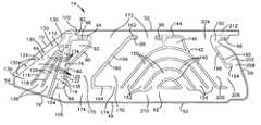
- FIG. 1is a schematic view illustrating an apparatus for helping to protect a vehicle occupant in a deflated condition, according to a first embodiment of the present invention
- FIG. 2is a schematic view of the apparatus of FIG. 1 in an inflated condition
- FIG. 3is a sectional view of the apparatus taken generally along line 3 — 3 in FIG. 2;
- FIG. 4is a schematic view of a portion of the apparatus of FIG. 2;
- FIG. 5is a schematic view illustrating an apparatus for helping to protect a vehicle occupant in an inflated condition, according to a second embodiment of the present invention.
- an apparatus 10helps to protect an occupant of a vehicle 12 .
- the apparatus 10includes an inflatable vehicle occupant protection device in the form of an inflatable curtain 14 that is mounted adjacent the side structure 16 of the vehicle 12 and a roof 18 of the vehicle.
- the roof 18may be either a standard roof that is fixed in place or a convertible roof that can be moved or removed.
- the side structure 16 of the vehicle 12includes side windows 20 , an A pillar 22 , a B pillar 24 , and a C pillar 26 .
- the side structure 16may also include a D pillar 28 .
- An inflator 30is connected in fluid communication with the inflatable curtain 14 through a fill tube 32 .
- the fill tube 32has a first end portion 34 for receiving fluid from the inflator 30 .
- the fill tube 32has a second end portion 36 disposed in the inflatable curtain 14 .
- the second end portion 36 of the fill tube 32has a plurality of openings (not shown) that provide fluid communication between the fill tube 32 and the inflatable curtain 14 .
- the inflator 30contains a stored quantity of pressurized inflation fluid (not shown) in the form of a gas for inflating the inflatable curtain 14 .
- the inflator 30alternatively could contain a combination of pressurized inflation fluid and ignitable material for heating the inflation fluid, or could be a pyrotechnic inflator that uses the combustion of gas-generating material to generate inflation fluid.
- the inflator 30could be of any suitable type or construction for supplying a medium for inflating the inflatable curtain 14 .
- the apparatus 10has a stored condition in which the inflatable curtain 14 is stored in a deflated condition. This is illustrated in FIG. 1 .
- the deflated inflatable curtain 14has an elongated configuration and extends along the vehicle roof 18 and along the side structure 16 of the vehicle 12 above the side windows 20 .
- a portion of the apparatus 10 of FIG. 1extends along the A pillar 22 of the vehicle 12 when the apparatus is in the stored position.
- the apparatus 10may include a housing (not shown) that houses the inflatable curtain 14 in the stored condition.
- the inflatable curtain 14comprises first and second panels 40 and 42 that are arranged in an overlying manner.
- the first and second panels 40 and 42are interconnected to form a perimeter connection 46 (FIGS. 2 and 3) that extends along a perimeter 48 of the panels.
- the first and second panels 40 and 42are also interconnected to form connections 70 within the perimeter 48 of the inflatable curtain 14 .
- the perimeter connection 46 and the connections 70are formed by weaving the panels 40 and 42 together.
- meanssuch as stitching, dielectric sealing, ultrasonic bonding, heat sealing, and adhesives may be used to interconnect the first and second panels 40 and 42 in order to form the perimeter connection 46 and the connections 70 .
- the curtainis formed by weaving the first and second panels 40 and 42 simultaneously while also interweaving the perimeter connection 46 and the connections 70 as single layers of fabric. This can be accomplished by using a Jacquard or Dobby weaving machine.
- the weaving machinesare pre-programmed to weave the first and second panels 40 and 42 along with the perimeter connection 46 and connections 70 at the same time. No intermediate steps are required.
- the curtainmay be formed by interconnecting two separate fabric pieces together along the perimeter connection 46 and the connections 70 .
- a single piece of fabricmay be folded over to form the overlying first and second panels 40 and 42 .
- the foldis part of the perimeter connection 46 of the inflatable curtain 14 .
- the inflatable curtain 14is constructed of a woven fabric, such as nylon, that is coated with a gas impermeable material, such as urethane or silicone.
- the inflatable curtain 14thus may have a substantially gas-tight construction.
- Other materials, such as elastomers, plastic films, or combinations thereof,may also be used to construct the inflatable curtain 14 , in which case the curtain may have a non-woven construction.
- the materials used to construct the inflatable curtain 14may also be single or multi-layered materials.
- the first and second panels 40 and 42 , the perimeter connection 46 , and the connections 70may be coated using a laminate film, slurry, and/or a spray coating, such as silicone, urethane, or other known suitable materials, in order to achieve a substantially gas-tight construction. This helps to prevent gas from permeating directly through the first and second panels 40 and 42 , the perimeter connection 46 , and the connections 70 .
- the perimeter 48 (FIG. 2) of the inflatable curtain 14is defined by upper and lower edges 50 and 52 , respectively, of the curtain and front and rear edges 54 and 56 , respectively, of the curtain that are spaced apart horizontally along the upper and lower edges.
- the perimeter connection 46 (FIG. 2)defines an inflatable volume 60 of the inflatable curtain 14 .
- the inflatable curtain 14includes an inflatable main portion 62 partially defined by the upper edge 50 , lower edge 52 , and rear edge 56 of the curtain.
- the main portion 62extends from the upper edge 50 to the lower edge 52 .
- the main portion 62is further defined by a first connection 80 of the inflatable curtain 14 .
- the first connection 80has a first end portion 82 that intersects the perimeter connection 46 adjacent the upper edge 50 of the inflatable curtain 14 .
- the first connection 80extends in a generally vertical direction from the upper edge 50 of the inflatable curtain 14 towards the lower edge 52 of the curtain.
- the first connection 80has a second end 84 , opposite the first end 82 , spaced from the perimeter connection 46 and positioned near the lower edge 52 .
- the inflatable curtain 14also includes an inflatable front portion 64 partially defined by the upper edge 50 , lower edge 52 , front edge 54 , and first connection 80 .
- the front portion 64has a generally triangular configuration. As illustrated in FIG. 2, the upper and lower edges 50 and 52 have portions that extend at an angle towards each other in the front portion 64 of the inflatable curtain 14 .
- the angled portion of the upper edge 50forms a forward edge 72 of the front portion 64 .
- the angled portion of the lower edge 52forms a bottom edge 74 of the front portion 64 .
- the first connection 80forms a rear edge 76 of the front portion 64 .
- the front edge 54 of the inflatable curtain 14extends a relatively short distance between terminal ends of the upper and lower edges 50 and 52 , i.e., between the forward edge 72 and bottom edge 74 of the front portion 64 .
- the front edge 54could, however, be omitted and the upper and lower edges 50 and 52 could be extended until they intersect, in which case the front portion 64 would be partially defined by the intersecting upper and lower edges.
- the first connection 80includes a generally triangular portion 90 adjacent the first end 82 that defines a generally triangular non-inflatable area 92 of the inflatable curtain 14 .
- An upper portion 94 of the triangular portion 90includes an aperture 96 for receiving a fastening device 100 (FIG. 2 ), such as a clamp, for connecting the inflatable curtain 14 and the fill tube 32 to the vehicle 12 .
- the upper portion 94extends in a generally horizontal direction as viewed in FIG. 4 and is spaced from the perimeter connection 46 .
- the upper portion 94helps define a pocket 102 for receiving the second end portion 36 (FIG. 2) of the fill tube 32 .
- the pocket 102surrounds the second end portion 36 of the fill tube 32 and forms a snug fit with the fill tube. The pocket 102 thus helps to position the fill tube 32 in the inflatable curtain 14 and helps to maintain the position of the fill tube relative to the curtain.
- the second end 84 (FIG. 4) of the first connection 80includes a portion 104 that extends in a generally horizontal direction as viewed in FIG. 4 and that is spaced from the perimeter connection 46 .
- a first inflation fluid passage 106is defined between the portion 104 and the portion of the perimeter connection 46 extending along the lower edge 52 adjacent the portion 104 .
- the first inflation fluid passage 106provides fluid communication between the main portion 62 and the front portion 64 .
- the front portion 64includes a connection 110 that has a three-pronged configuration and that extends in a direction generally diagonally downward and forward in the vehicle 12 as viewed in FIG. 2 .
- the connection 110(FIG. 4) includes a base portion 112 positioned near the forward edge 72 of the front portion 64 .
- the connection 110also includes three prong portions, identified at 114 , 116 , and 118 , that extend radially from the base portion 112 towards the bottom edge 74 of the front portion 64 .
- the prong portion 114 positioned closest to the first connection 80intersects the perimeter connection 46 along the bottom edge 74 .
- the second and third prong portions 116 and 118are spaced from the bottom edge 74 .
- the connection 110helps to define four inflatable chambers 120 in the front portion 64 .
- a first chamber 122 of the front portion 64extends from the intersection of the forward edge 72 and the rear edge 76 in a direction generally diagonally downward and forward along the rear edge 76 towards the bottom edge 74 .
- a second chamber 124 of the front portion 64extends from the intersection of the forward edge 72 and the rear edge 76 in a direction generally diagonally downward and forward along the forward edge 72 towards the bottom edge 74 .
- the two innermost chambers 126extend from the base portion 112 of the connection 110 in a direction generally diagonally downward and forward towards the bottom edge 74 of the front portion 64 .
- the inflatable curtain 14includes a plurality of fastener receiving apertures 130 spaced along the forward edge 72 of the front portion 64 of the curtain.
- the fastener receiving apertures 130extend through the perimeter connection 46 .
- the perimeter connection 46may be wide along the forward edge 72 in order to accommodate the apertures 130 .
- Each of the fastener receiving apertures 130receives a fastener 132 (FIG. 2 ), such as a bolt or screw, for helping to connect the inflatable curtain 14 to the vehicle 12 . More specifically, the fasteners 132 connect the front portion 64 of the inflatable curtain 14 to the A-pillar 22 of the vehicle 12 .
- the middle connections 140help to define three inflatable middle chambers 150 located in the main portion 62 of the inflatable curtain 14 .
- the middle chambers 150are generally arc-shaped, concentric, and are positioned facing concavely downward, as viewed in FIG. 4, toward the lower edge 52 of the inflatable curtain 14 .
- Each of the middle chambers 150includes first and second inflation fluid inlets 152 and 154 , respectively.
- the first and second inflation fluid inlets 152 and 154are positioned at opposite ends of the middle chambers 150 and near the lower edge 52 of the inflatable curtain 14 . None of the first and second inflation fluid inlets 152 and 154 is positioned near the upper edge 50 of the inflatable curtain 14 .
- the inflatable curtain 14also includes a front connection 160 located in the main portion 62 of the curtain.
- the front connection 160includes an upper end portion 162 , a lower end portion 164 and a middle portion 166 that extends between the upper and lower end portions.
- the upper end portion 162is positioned near the upper edge 50 of the inflatable curtain 14 and extends in a generally horizontal direction, as viewed in FIG. 4 .
- the upper end portion 162may include an aperture 96 for receiving a fastening device 100 .
- the lower end portion 164is positioned near the lower edge 52 of the inflatable curtain 14 and extends in a generally horizontal direction, as viewed in FIG. 4, towards the middle connections 150 .
- the middle portion 166 of the front connection 160extends generally diagonally between the upper and lower end portions 162 and 164 .
- the inflatable curtain 14also includes a rear connection 190 located in the main portion 62 of the curtain.
- the rear connection 190includes an upper end portion 192 , a lower end portion 194 and a middle portion 196 that extends between the upper and lower end portions.
- the upper end portion 192is spaced from the upper edge 50 of the inflatable curtain 14 and includes a portion that extends generally parallel to the upper edge of the curtain.
- the upper end portion 192intersects or coincides with the perimeter connection 46 along the rear edge 56 of the inflatable curtain 14 .
- the upper end portion 192may include an aperture 96 for receiving a fastening device 100 .
- the middle portion 196 of the rear connection 190extends generally diagonally between the upper and lower end portions 192 and 194 .
- the rear connection 190 , perimeter connection 46 , and the first middle connection 142help to define first and second inflatable rear chambers 200 and 202 , respectively, located in the main portion 62 of the inflatable curtain 14 .
- the first and second rear chambers 200 and 202extend in a generally diagonal direction between the upper and lower edges 50 and 52 of the inflatable curtain 14 .
- the first rear chamber 200includes an inflation fluid inlet 204 positioned near the upper edge 50 of the inflatable curtain 14 and an opposite inflation fluid outlet 206 .
- the second rear chamber 202includes an inflation fluid inlet 208 .
- the inflatable curtain 14also includes a bottom chamber 210 that extends along the lower edge 52 of the curtain in the main portion 62 of the curtain.
- the bottom chamber 210is in fluid communication with the front chambers 170 , middle chambers 150 , first and second rear chambers 200 and 202 , and the front portion 64 of the inflatable curtain 14 .
- the inflatable curtain 14further includes an opening 212 for receiving the first end portion 34 of the fill tube 32 .
- the opening 212is defined between the perimeter connection 46 and the upper portion 192 of the rear connection 190 near the intersection of the rear edge 56 and the upper edge 50 of the inflatable curtain 14 .
- the opening 212receives the fill tube 32 when the fill tube is inserted into the inflatable curtain 14 .
- the portions of the curtain that define the opening 212encircle the first end portion 34 of the fill tube 32 and form a snug fit with the fill tube.
- the opening 212thus helps to position the fill tube 32 in the inflatable curtain 14 and helps to maintain the position of the fill tube relative to the curtain.
- the upper end portion 162 of the front connection 160 and the portion 144 of the first middle connection 140are spaced from the upper edge 50 of the inflatable curtain 14 a distance slightly larger than the diameter of the fill tube 32 .
- the upper end portion 162 and the portion 144thus help guide the fill tube 32 into the inflatable curtain 14 when the tube is inserted into the curtain.
- the upper end portion 162 and the portion 144also help to position the fill tube 32 in the inflatable curtain 14 and help to maintain the position of the fill tube relative to the curtain.
- the apparatus 10may include an anchor mechanism 260 for helping to connect the inflatable curtain 14 to the vehicle 12 .
- the anchor mechanism 260connects the inflatable curtain 14 to the C pillar 26 of the vehicle 12 .
- the anchor mechanism 260includes a track 262 connected to the C pillar 26 that extends generally vertically or at a substantially vertical angle along the C pillar.
- the anchor mechanism 260also includes an element 264 that is slidable along the track.
- a flexible elongated member 266such as a tether, has a first end connected to the element 264 and an opposite second end connected to the inflatable curtain 14 adjacent the lower edge 52 of the curtain near the intersection of the lower edge and the rear edge 56 of the curtain.
- the vehicle 12includes a sensor mechanism 270 (shown schematically in FIGS. 1 and 2) for sensing a side impact to the vehicle 12 and/or a rollover of the vehicle 12 .
- the sensor mechanism 270actuates the inflator 30 in response to the sensing of a side impact or a vehicle rollover.
- the sensor mechanism 270provides an electrical signal over lead wires 272 to the inflator 30 .
- the electrical signalcauses the inflator 30 to be actuated in a known manner.
- the inflator 30discharges fluid under pressure into the fill tube 32 .
- the fill tube 32directs the fluid into the main portion 62 of the inflatable curtain 14 .
- the inflatable curtain 14inflates under the pressure of the inflation fluid from the inflator 30 .
- the inflatable curtain 14inflates away from the roof 18 in a downward direction as shown in the drawings and in a downward direction with respect to the direction of forward travel of the vehicle 12 into the position illustrated in FIG. 2 .
- the inflatable curtain 14when inflated, extends along the side structure 16 of the vehicle 12 and is positioned between the side structure and any occupant of the vehicle.
- the first panel 40(FIG. 3) is positioned adjacent the side structure 16 of the vehicle 12 .
- the upper edge 50 (FIG. 2) of the inflatable curtain 14is positioned adjacent the intersection of the roof 18 and the side structure 16 of the vehicle 12 .
- the front edge 54 of the inflatable curtain 14is positioned adjacent the A pillar 22 of the vehicle 12 .
- the rear edge 56 of the inflatable curtain 14is positioned adjacent the C pillar 26 of the vehicle 12 .
- the inflatable curtain 14extends between the A pillar 22 and the C pillar 26 of the vehicle 12 and may overlie portions of the A pillar, C pillar, and B pillar 24 of the vehicle.
- the inflatable curtainmay have alternative configurations.
- the inflatable curtain 14extends between the A pillar 22 and the C pillar 26 of the vehicle 12 .
- the inflatable curtain 14could, however, extend between the A pillar 22 and the B pillar 24 only or between the B pillar and the C pillar 26 only.
- the inflatable curtain 14could extend between the A pillar 22 and the D pillar 28 of the vehicle 12 .
- the inflatable curtain 14when inflated, helps to protect a vehicle occupant in the event of a vehicle rollover or a side impact to the vehicle 12 .
- the connections 70help to limit the thickness of the inflated inflatable curtain 14 and help to reduce the overall volume of the curtain.
- the front chambers 170 (FIG. 4 ), middle chambers 150 , rear chambers 200 and 202 , and bottom chamber 210 of the main portion 62when inflated, help to absorb the energy of impacts with the inflatable curtain 14 and help to distribute the impact energy over a large area of the curtain.
- the chambers 120 of the front portion 64also help to absorb the energy of impacts with the inflatable curtain 14 and help to distribute the impact energy over a large area of the curtain.
- inflation fluidis directed from the fill tube 32 into the main portion 62 of the curtain.
- the inflation fluidis directed into the front chambers 170 through the inflation fluid inlets 172 and into the first rear chamber 200 through the inflation fluid inlet 204 .
- the inflation fluidinflates the front chambers 170 and the first rear chamber 200 and then exits the chambers through the inflation fluid outlets 174 and 206 , respectively.
- the fluidis directed into the bottom chamber 210 and through the first and second inflation fluid inlets 152 and 154 into the middle chambers 150 .
- Inflation fluidis also directed through the inflation fluid inlet 208 into the second rear chamber 202 .
- Inflation fluidis also directed from the bottom chamber 210 into the front portion 64 through the first inflation fluid passage 106 .
- the inflation fluidenters the front portion 64 and inflates the chambers 120 of the front portion.
- the outermost chambers 122 and 124 of the front portion 64are inflated before the innermost chambers 126 of the front portion are inflated.
- the chambers 120 of the front portion 64when inflated, expand radially, which causes the front portion to contract in a direction perpendicular to the length of the chambers, i.e., in a direction generally along the length of the inflatable curtain 14 .
- the degree or distance that the chambers contractis related directly to the width of the chambers.
- the wide portions 136 of the chambers 120thus contract to a greater degree or distance than the narrow portions 134 of the chambers.
- the front portion 64when inflated, experiences the greatest amount of contraction along the bottom edge 74 because the wide portions 136 of the chambers 120 are positioned adjacent the bottom edge.
- the front portion 64when inflated, thus contracts lengthwise, i.e., along the length of the inflatable curtain 14 as measured in a generally horizontal direction, as viewed in FIG. 2 .
- the inflatable curtain 14being connected to the A pillar 22 via the fasteners 132 and being connected to the C pillar 26 via the anchor mechanism 260 , is thus tensioned between the A pillar and C pillar when the front portion 64 contracts lengthwise. This helps to maintain the inflatable curtain 14 in the inflated position of FIG. 2 throughout the duration of a side impact to the vehicle 12 and/or a vehicle rollover.
- the front chambers 170 and the first rear chamber 200begin to inflate before the middle chambers 150 begin to inflate.
- the rate at which the middle chambers 150 inflatedepends partially upon the size of the inflation fluid outlets 174 and 206 , as well as the size of the inflation fluid inlets 152 and 154 .
- the front chambers 170 and the first rear chamber 200thus may be substantially inflated before the middle chambers 150 begin to inflate.
- the first rear chamber 200begins to inflate before the second rear chamber 202 begins to inflate.
- the rate at which the second rear chamber 202 inflatesdepends partially upon the size of the inflation fluid outlet 206 and the inflation fluid inlets 208 .
- the first rear chamber 200thus may be substantially inflated before the second rear chamber 202 .
- FIG. 5A second embodiment of the present invention is illustrated in FIG. 5 .
- the second embodiment of the inventionis similar to the first embodiment of the invention illustrated in FIGS. 1-4. Accordingly, numerals similar to those of FIGS. 1-4 will be used in FIG. 5 to identify similar components, the suffix letter “a” being associated with the numerals of FIG. 5 to avoid confusion.
- the inflatable curtain 14 aincludes an inflatable rear portion 300 in addition to the front portion 64 a and main portion 62 a .
- the main portion 62 ais thus positioned between the front portion 64 a and the rear portion 300 .
- the rear portion 300has a generally triangular configuration.
- a forward edge 302 of the rear portion 300is defined by a second connection 310 .
- a rear edge 304 of the rear portion 300is defined by the rear edge 56 a of the inflatable curtain 14 a .
- a bottom edge 306 of the rear portion 300is defined by a portion of the lower edge 52 a of the inflatable curtain 14 a.
- the second connection 310has a first end 312 and an opposite second end 314 .
- the first end 312has a portion 316 that is spaced from the upper edge 50 a and that intersects the perimeter connection 46 a at the rear edge 56 a of the curtain 14 a .
- the portion 316 and the perimeter connection 46 adefine the opening 252 a .
- the second end 314is spaced from the perimeter connection 46 a and positioned near the lower edge 52 a .
- the second connection 310extends in a generally diagonal direction from the opening 252 a towards the lower edge 52 a and the rear edge 56 a of the inflatable curtain 14 a.
- the second end 314 of the second connection 300includes a portion 320 that extends generally parallel to the lower edge 52 a and is spaced from the perimeter connection 46 a .
- a second inflation fluid passage 322is defined between the second end 314 of the first connection 300 and the portion of the perimeter connection 46 a extending along the lower edge 52 a adjacent the second end 314 .
- the second inflation fluid passage 322provides fluid communication between the main portion 62 a and the rear portion 300 .
- the rear portion 300includes a connection 330 that has a generally inverted V-shaped configuration.
- the connection 330extends in a direction generally diagonally downward and rearward in the vehicle 12 a , as viewed in FIG. 5 .
- the connection 330includes a base portion 332 and two prong portions 334 that extend from the base portion.
- the base portion 332is positioned near the intersection of the forward edge 302 and rear edge 304 of the rear portion 300 .
- the prong portions 334extend from the base portion towards the bottom edge 306 of the rear portion 300 .
- the inflatable curtain 14 aincludes a plurality of fastener receiving apertures 350 spaced along the rear edge 56 a of the curtain.
- the fastener receiving apertures 350extend through the perimeter connection 46 a . Because of this, the perimeter connection 46 a may be wide along the rear edge 56 a of the inflatable curtain 14 a .
- the fastener receiving apertures 350receive fasteners (not shown), such as bolts or screws, for helping to connect the inflatable curtain 14 a to the vehicle 12 a . More specifically, the fasteners extending through the apertures 350 along the rear edge 56 a connect the rear portion 300 to the C pillar 26 a of the vehicle 12 a.
- the first rear chamber 200 a of the inflatable curtain 14 ais similar to the first rear chamber 200 (FIGS. 1-4) of the first embodiment.
- the main portion 62 a (FIG. 5) of the second embodimentincludes four middle connections 140 a that help define three inflatable middle chambers 150 a of the main portion and a front connection 160 a that helps define two inflatable front chambers 170 a of the main portion.
- the front portion 64 a (FIG. 5) of the second embodimentincludes a connection 110 a that defines four inflatable chambers 120 a of the front portion.
- the front portion 64 aalso includes fastener receiving apertures 130 a spaced along the upper edge 50 a of the curtain.
- the inflator 30 ais actuated by the sensor mechanism 270 a in a manner similar or identical to the apparatus 10 (FIGS. 1-4) of the first embodiment.
- the inflator 30 a(FIG. 5) discharges fluid under pressure into the fill tube 32 a , which directs the fluid into the main portion 62 a of the inflatable curtain 14 a .
- the inflatable curtain 14 ainflates under the pressure of the inflation fluid from the inflator 30 a into the position illustrated in FIG. 5 .
- the inflatable curtain 14 awhen inflated, helps to protect a vehicle occupant in the event of a vehicle rollover or a side impact to the vehicle 12 a .
- the connections 70 ahelp to limit the thickness of the inflated inflatable curtain 14 a and help to reduce the overall volume of the curtain.
- the front chambers 170 a , middle chambers 150 a , first rear chamber 200 a , and bottom chamber 210 a of the main portion 62 awhen inflated, help to absorb the energy of impacts with the inflatable curtain 14 a and help to distribute the impact energy over a large area of the curtain.
- the chambers 120 a of the front portion 64 a and the chambers 340 of the rear portion 300also help to absorb the energy of impacts with the inflatable curtain 14 a and help to distribute the impact energy over a large area of the curtain.
- inflation fluidis directed from the fill tube 32 a into the main portion 62 a of the curtain.
- the inflation fluidis directed into the front chambers 170 a through the inflation fluid inlets 172 a and into the first rear chamber 200 a through the inflation fluid inlet 202 a .
- the inflation fluidinflates the front chambers 170 a and the first rear chamber 200 a and then exits the chambers through the inflation fluid outlets 174 a and 204 a .
- the inflation fluidexits the front chambers 170 a and the first rear chamber 200 a , the fluid is directed into the bottom chamber 210 a and through the first and second inflation fluid inlets 152 a and 154 a into the middle chambers 150 a.
- Inflation fluidis also directed from the bottom chamber 210 a into the front portion 64 a through the first inflation fluid passage 106 a and into the rear portion 300 through the second inflation fluid passage 322 .
- Inflation fluidenters the front portion 64 a and inflates the chambers 120 a of the front portion.
- Inflation fluidalso enters the rear portion 300 and inflates the chambers 340 of the rear portion.
- the outermost chambers 122 a and 124 a of the front portion 64 aare inflated before the innermost chambers 126 a of the front portion, whereas the outermost chambers 342 and innermost chamber 344 of the rear portion 300 are inflated at about the same time.
- the chambers 120 a and 340 of the front and rear portions 64 a and 300respectively, when inflated, expand radially, which causes the chambers to contract in a direction perpendicular to the length of the chambers.
- the chambers 120 a of the front portion 64 awhen inflated, expand radially, which causes the front portion to contract in a direction perpendicular to the length of the chambers, i.e., in a direction generally along the length of the inflatable curtain 14 a .
- the degree or distance that the chambers contractis related directly to the width of the chamber.
- the wide portions 136 a of the chambers 120 athus contract to a greater degree or distance than the narrow portions 134 a of the chambers.
- the front portion 64 awhen inflated, experiences the greatest amount of contraction along the bottom edge 74 a because the wide portions 136 a of the chambers 120 a are positioned adjacent the bottom edge.
- the chambers 340 of the rear portion 300when inflated, expand radially, which causes the front portion to contract in a direction perpendicular to the length of the chambers, i.e., in a direction generally along the length of the inflatable curtain 14 a .
- the degree or distance that the chambers contractis related directly to the width of the chamber.
- the wide portions 348 of the chambers 340thus contract to a greater degree or distance than the narrow portions 346 of the chambers.
- the rear portion 300when inflated, experiences the greatest amount of contraction along the bottom edge 306 because the wide portions 348 of the chambers 340 are positioned adjacent the bottom edge.
- the front and rear portions 64 a and 300thus contract lengthwise along the length of the inflatable curtain 14 a , as measured in a generally horizontal direction, as viewed in FIG. 5 .
- the inflatable curtain 14 abeing connected to the vehicle 12 a along the A pillar 22 a and the C pillar 26 a , is thus tensioned between the A pillar and C pillar when the front and rear portions 64 a and 300 contract lengthwise due to the inflation of the chambers 120 a and 340 . This helps to maintain the inflatable curtain 14 a in the inflated position of FIG. 5 throughout the duration of a side impact to the vehicle 12 a and/or a vehicle rollover.
- the front portion 64 abegins to inflate after the main portion 62 a begins to inflate. More specifically, the front chambers 170 a and the first rear chamber 200 a begin to inflate before the front portion 64 a begins to inflate.
- the rate at which the front portion 64 a is inflateddepends partially upon the size of the first inflation fluid passage 106 a , i.e., the distance between the second end 84 a of the first connection 80 a and the perimeter connection 46 a .
- the front portion 64 amay thus be inflated at a desired rate by adjusting the first inflation fluid passage 106 a to an appropriate size.
- the main portion 62 amay, therefore, be substantially inflated before the front portions 64 a is inflated.
- the rear portion 300begins to inflate after the main portion 62 a begins to inflate. More specifically, the front chambers 170 a and the first rear chamber 200 a begin to inflate before the rear portion 300 begins to inflate.
- the rate at which the rear portion 300 is inflateddepends partially upon the size of the second inflation fluid passage 322 , i.e., the distance between the second end 320 of the second connection 310 and the perimeter connection 46 a .
- the rear portion 300may thus be inflated at a desired rate by adjusting the second inflation fluid passage 322 to an appropriate size.
- the main portion 62 amay, therefore, be substantially inflated before the rear portion 300 is inflated.
- the front chambers 170 a and the first rear chamber 200 abegin to inflate before the middle chambers 150 a begin to inflate.
- the rate at which the middle chambers 150 a inflatedepends partially on the size of the inflation fluid outlets 174 a and 204 a and the size of the inflation fluid inlets 152 a and 154 a .
- the front chambers 170 a and the first rear chamber 200 amay thus be substantially inflated before the middle chambers 150 a begin to inflate.
- the front chambers, rear chambers, middle chambers and bottom chamber of the inflatable curtain in the first and second embodimentmay be defined by connections having shapes and configurations different than the connections illustrated in the respective embodiments.
- separate front, middle and rear connectionsdefine the front, middle and rear chambers of the inflatable curtain.
- the front, middle and rear chamberscould, however, be defined by a single connection.
Landscapes
- Engineering & Computer Science (AREA)
- Mechanical Engineering (AREA)
- Air Bags (AREA)
Abstract
Description
Claims (29)
Priority Applications (2)
| Application Number | Priority Date | Filing Date | Title |
|---|---|---|---|
| US09/963,289US6527296B2 (en) | 2000-03-17 | 2001-09-26 | Inflatable side curtain |
| DE10147965ADE10147965B4 (en) | 2000-09-28 | 2001-09-28 | Inflatable side curtain |
Applications Claiming Priority (6)
| Application Number | Priority Date | Filing Date | Title |
|---|---|---|---|
| US19019900P | 2000-03-17 | 2000-03-17 | |
| US57916200A | 2000-05-25 | 2000-05-25 | |
| US67254700A | 2000-09-28 | 2000-09-28 | |
| US09/946,287US6431590B1 (en) | 2000-09-28 | 2001-09-05 | Inflatable side curtain |
| US09/956,227US6471240B2 (en) | 2000-03-17 | 2001-09-19 | Inflatable side curtain |
| US09/963,289US6527296B2 (en) | 2000-03-17 | 2001-09-26 | Inflatable side curtain |
Related Parent Applications (1)
| Application Number | Title | Priority Date | Filing Date |
|---|---|---|---|
| US09/946,287Continuation-In-PartUS6431590B1 (en) | 2000-03-17 | 2001-09-05 | Inflatable side curtain |
Publications (2)
| Publication Number | Publication Date |
|---|---|
| US20020036394A1 US20020036394A1 (en) | 2002-03-28 |
| US6527296B2true US6527296B2 (en) | 2003-03-04 |
Family
ID=27418246
Family Applications (1)
| Application Number | Title | Priority Date | Filing Date |
|---|---|---|---|
| US09/963,289Expired - LifetimeUS6527296B2 (en) | 2000-03-17 | 2001-09-26 | Inflatable side curtain |
Country Status (2)
| Country | Link |
|---|---|
| US (1) | US6527296B2 (en) |
| DE (1) | DE10147965B4 (en) |
Cited By (33)
| Publication number | Priority date | Publication date | Assignee | Title |
|---|---|---|---|---|
| US6648368B2 (en)* | 2002-03-27 | 2003-11-18 | General Motors Corporation | Dual roof rail air bag with integrated fill system |
| US6655713B2 (en)* | 2000-06-30 | 2003-12-02 | Toyoda Gosei Co., Ltd. | Air bag |
| US20030222437A1 (en)* | 2002-03-19 | 2003-12-04 | Takata Corporation | Head protective airbag and device |
| US20040041376A1 (en)* | 2000-12-08 | 2004-03-04 | Jochen Winkler | Air-bag arrangement |
| US6709010B2 (en)* | 2001-11-09 | 2004-03-23 | Autoliv Asp, Inc. | Rear tether retractor for an inflatable cushion |
| US20040130128A1 (en)* | 2003-01-07 | 2004-07-08 | Trw Vehicle Safety Systems Inc. | Inflatable curtain |
| US20040178608A1 (en)* | 2003-03-13 | 2004-09-16 | Takata Corporation | Curtain airbag system and guide mechanism thereof |
| US20050116450A1 (en)* | 2003-12-02 | 2005-06-02 | Takata Corporation | Airbag apparatus |
| US20050121885A1 (en)* | 2003-12-05 | 2005-06-09 | Elesys North America, Inc. | Vehicle occupant sensing system |
| US20050134025A1 (en)* | 2003-12-19 | 2005-06-23 | Trw Vehicle Safety Systems Inc. | Inflatable curtain |
| US20050156413A1 (en)* | 2004-01-20 | 2005-07-21 | Breed Automative Technology, Inc. | Side impact air bag with head protection region |
| US20050167957A1 (en)* | 2003-12-19 | 2005-08-04 | Takata Corporation | Curtain airbag device |
| US20050189743A1 (en)* | 2004-02-26 | 2005-09-01 | Trw Vehicle Safety Systems Inc. | Inflatable curtain with extension portion |
| US20050275200A1 (en)* | 2004-06-14 | 2005-12-15 | Takata Corporation | Curtain airbag device |
| US20050285378A1 (en)* | 2004-06-29 | 2005-12-29 | Takata Corporation | Curtain airbag device |
| US20060208466A1 (en)* | 2005-03-18 | 2006-09-21 | Takata Restraint Systems, Inc. | Curtain airbag bottom fill |
| US20060273558A1 (en)* | 1994-05-23 | 2006-12-07 | Automotive Technologies International, Inc. | Vehicle with side curtain, multi-compartment airbag |
| US20070052212A1 (en)* | 2005-09-08 | 2007-03-08 | Powals Brian J | Extended inflatable coverage of inflatable curtains |
| US20070164543A1 (en)* | 2003-10-27 | 2007-07-19 | Masataka Fukuda | Side curtain air bag |
| US7261316B1 (en)* | 2006-12-22 | 2007-08-28 | Key Safety Systems, Inc. | Side curtain airbag assembly |
| US20080054605A1 (en)* | 2006-08-31 | 2008-03-06 | Toyota Jidosha Kabushiki Kaisha | Head protecting airbag system |
| US20080243342A1 (en)* | 1995-12-12 | 2008-10-02 | Automotive Technologies International, Inc. | Side Curtain Airbag With Inflator At End |
| US20080309056A1 (en)* | 2007-06-13 | 2008-12-18 | Yoshihiro Ohba | Curtain airbag system |
| US20090184499A1 (en)* | 2008-01-18 | 2009-07-23 | Tk Holdings Inc. | Curtain airbag |
| US20100164210A1 (en)* | 2006-01-18 | 2010-07-01 | Takata Corporation | Airbag And Airbag Device |
| US20100171293A1 (en)* | 2007-07-11 | 2010-07-08 | Toshiharu Yamamoto | Curtain bag |
| US20100264630A1 (en)* | 2009-04-17 | 2010-10-21 | Autoliv Asp, Inc. | Inflatable curtain airbags with expanded-volume lower portions for ejection mitigation |
| US20120119476A1 (en)* | 2010-11-16 | 2012-05-17 | Mazda Motor Corporation | Passenger protection of vehicle |
| US20120313356A1 (en)* | 2011-06-13 | 2012-12-13 | Toyoda Gosei Co., Ltd. | Curtain airbag system |
| US20130134694A1 (en)* | 2010-08-06 | 2013-05-30 | Autoliv Development Ab | Curtain airbag |
| US8608193B1 (en) | 2013-03-12 | 2013-12-17 | Trw Vehicle Safety Systems Inc. | Inflatable side curtain |
| US11192518B2 (en)* | 2019-04-12 | 2021-12-07 | Hyundai Mobis Co., Ltd. | Curtain air bag device |
| US11267422B2 (en)* | 2016-10-24 | 2022-03-08 | Trw Automotive Gmbh | Air bag module |
Families Citing this family (8)
| Publication number | Priority date | Publication date | Assignee | Title |
|---|---|---|---|---|
| US6846010B2 (en)* | 2002-01-30 | 2005-01-25 | Autoliv Asp, Inc. | Pressure equalizing curtain airbag |
| GB2393154A (en)* | 2002-09-20 | 2004-03-24 | Autoliv Dev | Curtain airbag extending below vehicle window |
| US7000944B2 (en) | 2002-11-22 | 2006-02-21 | Trw Vehicle Safety Systems Inc. | Inflatable windshield curtain |
| US20050046159A1 (en)* | 2003-09-01 | 2005-03-03 | Takata Corporation | Curtain airbag apparatus |
| JP2005178605A (en)* | 2003-12-19 | 2005-07-07 | Takata Corp | Curtain air bag device |
| JP4992784B2 (en)* | 2008-03-24 | 2012-08-08 | 豊田合成株式会社 | Head protection airbag |
| JP5627398B2 (en)* | 2010-11-04 | 2014-11-19 | 日本プラスト株式会社 | Curtain airbag |
| KR20250065051A (en)* | 2023-11-03 | 2025-05-12 | 현대모비스 주식회사 | Airbag Assembly |
Citations (37)
| Publication number | Priority date | Publication date | Assignee | Title |
|---|---|---|---|---|
| US3731949A (en) | 1971-05-12 | 1973-05-08 | Allied Chem | Flat bag made of tubular sections |
| DE4134995C1 (en) | 1991-10-23 | 1993-03-18 | Guenter 8152 Feldkirchen-Westerham De Herrmann | Sideways impact protection device - has inflatable cushion which is mounted at side of vehicle with sensor that detects impacts to initiates inflation |
| DE4307175A1 (en) | 1992-03-18 | 1993-09-23 | Volkswagen Ag | Air bag system giving side protection in vehicle - has set of air bags arranged to inflate and cover side window area |
| US5427410A (en) | 1993-06-07 | 1995-06-27 | Takata Corporation | Air bag with large size and small volume |
| US5439247A (en) | 1992-09-29 | 1995-08-08 | Trw Repa Gmbh | Inflatable gas bag for a vehicular restraining system |
| US5524924A (en) | 1993-11-15 | 1996-06-11 | Trw Vehicle Safety Systems Inc. | Method and apparatus for restraining an occupant of a vehicle upon a side impact against the vehicle |
| US5588672A (en) | 1995-10-20 | 1996-12-31 | Takata, Inc. | Side impact head restraint with inflatable deployment |
| GB2314300A (en) | 1996-06-20 | 1997-12-24 | Autoliv Dev | Airbag having tubular conduit folded back on itself for delivery of inflation gas. |
| US5730463A (en) | 1995-12-13 | 1998-03-24 | General Motors Corporation | Air Bag Fold And Method |
| DE19743626A1 (en) | 1996-10-03 | 1998-04-09 | Toyo Tire & Rubber Co | Side airbag for vehicle |
| US5788270A (en) | 1995-02-20 | 1998-08-04 | Autoliv Development Ab | Side impact and roll over inflatable head protector |
| US5865462A (en) | 1996-09-19 | 1999-02-02 | Breed Automotive Technology, Inc. | Inflatable restraint for a vehicle occupant |
| US5884937A (en) | 1995-11-12 | 1999-03-23 | Toyota Jidosha Kabushiki Kaisha | Air bag device |
| US5899490A (en) | 1997-06-13 | 1999-05-04 | Breed Automotive Technology, Inc. | Method of folding an air bag |
| US5899491A (en) | 1997-04-30 | 1999-05-04 | Daimler-Benz Aktiengesellschaft | Vehicle window air bag curtain |
| US5924723A (en) | 1997-06-27 | 1999-07-20 | Breed Automotive Technology, Inc. | Side safety barrier device |
| US5957487A (en) | 1996-03-29 | 1999-09-28 | Trw Occupant Restraint Systems Gmbh | Lateral impact protective device for vehicle occupants |
| US5960611A (en) | 1995-05-05 | 1999-10-05 | Autoliv Development Ab | Process for folding an airbag for a passenger restraint system |
| DE29914637U1 (en) | 1999-08-20 | 1999-12-09 | Takata Corp | Protective pad for the head of a vehicle occupant |
| US6010149A (en) | 1997-04-11 | 2000-01-04 | Autoliv Development Ab | Air-bag arrangement |
| US6032977A (en) | 1996-04-24 | 2000-03-07 | Daimler-Chrysler Aktiengesellschaft | Gas bag |
| US6073961A (en) | 1998-02-20 | 2000-06-13 | Breed Automotive Technology, Inc. | Inflatable side airbag curtain module |
| US6082761A (en) | 1997-01-24 | 2000-07-04 | Toyoda Gosei Co., Ltd. | Side airbag device |
| US6135492A (en) | 1998-02-14 | 2000-10-24 | Delphi Technologies, Inc. | Air bag module |
| US6155596A (en) | 1997-09-04 | 2000-12-05 | Toyota Jidosha Kabushiki Kaisha | Head-protecting air bag apparatus |
| US6168191B1 (en) | 1999-06-11 | 2001-01-02 | Delphi Technologies, Inc. | Inflatable air bag for an automotive vehicle |
| US6170860B1 (en) | 1997-05-28 | 2001-01-09 | Trw Occupant Restraint Systems Gmbh & Co. Kg | Gas bag for a vehicular occupant restraint system |
| US6186534B1 (en) | 1997-08-20 | 2001-02-13 | Dr. Ing. H.C. F. Porsche Ag | Air bag impact protection arrangement and process for folding an air bag |
| US6199898B1 (en) | 1998-08-20 | 2001-03-13 | Takata Corporation | Protective cushion for vehicle occupant's head |
| US6220625B1 (en) | 2000-01-03 | 2001-04-24 | Trw Vehicle Safety Systems Inc. | Inflatable side curtain |
| US6237937B1 (en) | 1998-06-23 | 2001-05-29 | Takata Corporation | Protective bag for vehicle occupant's head |
| US6244619B1 (en)* | 1999-06-25 | 2001-06-12 | Autoliv Development Ab | Safety arrangement |
| US6250668B1 (en) | 1994-05-23 | 2001-06-26 | Automotive Technologies International, Inc. | Tubular airbag, method of making the same and occupant protection system including the same |
| US6273456B1 (en)* | 1998-08-20 | 2001-08-14 | Trw Occupant Restraint Systems Gmbh & Co. Kg | Gas bag |
| US6336654B1 (en)* | 1999-12-09 | 2002-01-08 | Trw Vehicle Safety Systems Inc. | Inflatable side curtain |
| US6338498B1 (en)* | 2000-10-26 | 2002-01-15 | Delphi Technologies, Inc | Side air bag providing enhanced coverage |
| US6394487B1 (en)* | 1999-11-25 | 2002-05-28 | Takata (Europe) Vehicle Safety Technology Gmbh | Inflatable airbag |
- 2001
- 2001-09-26USUS09/963,289patent/US6527296B2/ennot_activeExpired - Lifetime
- 2001-09-28DEDE10147965Apatent/DE10147965B4/ennot_activeExpired - Fee Related
Patent Citations (38)
| Publication number | Priority date | Publication date | Assignee | Title |
|---|---|---|---|---|
| US3731949A (en) | 1971-05-12 | 1973-05-08 | Allied Chem | Flat bag made of tubular sections |
| DE4134995C1 (en) | 1991-10-23 | 1993-03-18 | Guenter 8152 Feldkirchen-Westerham De Herrmann | Sideways impact protection device - has inflatable cushion which is mounted at side of vehicle with sensor that detects impacts to initiates inflation |
| DE4307175A1 (en) | 1992-03-18 | 1993-09-23 | Volkswagen Ag | Air bag system giving side protection in vehicle - has set of air bags arranged to inflate and cover side window area |
| US5439247A (en) | 1992-09-29 | 1995-08-08 | Trw Repa Gmbh | Inflatable gas bag for a vehicular restraining system |
| US5427410A (en) | 1993-06-07 | 1995-06-27 | Takata Corporation | Air bag with large size and small volume |
| US5524924A (en) | 1993-11-15 | 1996-06-11 | Trw Vehicle Safety Systems Inc. | Method and apparatus for restraining an occupant of a vehicle upon a side impact against the vehicle |
| US6250668B1 (en) | 1994-05-23 | 2001-06-26 | Automotive Technologies International, Inc. | Tubular airbag, method of making the same and occupant protection system including the same |
| US5788270A (en) | 1995-02-20 | 1998-08-04 | Autoliv Development Ab | Side impact and roll over inflatable head protector |
| US5960611A (en) | 1995-05-05 | 1999-10-05 | Autoliv Development Ab | Process for folding an airbag for a passenger restraint system |
| US5588672A (en) | 1995-10-20 | 1996-12-31 | Takata, Inc. | Side impact head restraint with inflatable deployment |
| US5884937A (en) | 1995-11-12 | 1999-03-23 | Toyota Jidosha Kabushiki Kaisha | Air bag device |
| US5730463A (en) | 1995-12-13 | 1998-03-24 | General Motors Corporation | Air Bag Fold And Method |
| US5957487A (en) | 1996-03-29 | 1999-09-28 | Trw Occupant Restraint Systems Gmbh | Lateral impact protective device for vehicle occupants |
| US6032977A (en) | 1996-04-24 | 2000-03-07 | Daimler-Chrysler Aktiengesellschaft | Gas bag |
| GB2314300A (en) | 1996-06-20 | 1997-12-24 | Autoliv Dev | Airbag having tubular conduit folded back on itself for delivery of inflation gas. |
| US5865462A (en) | 1996-09-19 | 1999-02-02 | Breed Automotive Technology, Inc. | Inflatable restraint for a vehicle occupant |
| DE19743626A1 (en) | 1996-10-03 | 1998-04-09 | Toyo Tire & Rubber Co | Side airbag for vehicle |
| US6056316A (en) | 1996-10-03 | 2000-05-02 | Toyo Tire & Rubber Co., Ltd. | Side air bag |
| US6082761A (en) | 1997-01-24 | 2000-07-04 | Toyoda Gosei Co., Ltd. | Side airbag device |
| US6010149A (en) | 1997-04-11 | 2000-01-04 | Autoliv Development Ab | Air-bag arrangement |
| US5899491A (en) | 1997-04-30 | 1999-05-04 | Daimler-Benz Aktiengesellschaft | Vehicle window air bag curtain |
| US6170860B1 (en) | 1997-05-28 | 2001-01-09 | Trw Occupant Restraint Systems Gmbh & Co. Kg | Gas bag for a vehicular occupant restraint system |
| US5899490A (en) | 1997-06-13 | 1999-05-04 | Breed Automotive Technology, Inc. | Method of folding an air bag |
| US5924723A (en) | 1997-06-27 | 1999-07-20 | Breed Automotive Technology, Inc. | Side safety barrier device |
| US6186534B1 (en) | 1997-08-20 | 2001-02-13 | Dr. Ing. H.C. F. Porsche Ag | Air bag impact protection arrangement and process for folding an air bag |
| US6155596A (en) | 1997-09-04 | 2000-12-05 | Toyota Jidosha Kabushiki Kaisha | Head-protecting air bag apparatus |
| US6135492A (en) | 1998-02-14 | 2000-10-24 | Delphi Technologies, Inc. | Air bag module |
| US6073961A (en) | 1998-02-20 | 2000-06-13 | Breed Automotive Technology, Inc. | Inflatable side airbag curtain module |
| US6237937B1 (en) | 1998-06-23 | 2001-05-29 | Takata Corporation | Protective bag for vehicle occupant's head |
| US6273456B1 (en)* | 1998-08-20 | 2001-08-14 | Trw Occupant Restraint Systems Gmbh & Co. Kg | Gas bag |
| US6199898B1 (en) | 1998-08-20 | 2001-03-13 | Takata Corporation | Protective cushion for vehicle occupant's head |
| US6168191B1 (en) | 1999-06-11 | 2001-01-02 | Delphi Technologies, Inc. | Inflatable air bag for an automotive vehicle |
| US6244619B1 (en)* | 1999-06-25 | 2001-06-12 | Autoliv Development Ab | Safety arrangement |
| DE29914637U1 (en) | 1999-08-20 | 1999-12-09 | Takata Corp | Protective pad for the head of a vehicle occupant |
| US6394487B1 (en)* | 1999-11-25 | 2002-05-28 | Takata (Europe) Vehicle Safety Technology Gmbh | Inflatable airbag |
| US6336654B1 (en)* | 1999-12-09 | 2002-01-08 | Trw Vehicle Safety Systems Inc. | Inflatable side curtain |
| US6220625B1 (en) | 2000-01-03 | 2001-04-24 | Trw Vehicle Safety Systems Inc. | Inflatable side curtain |
| US6338498B1 (en)* | 2000-10-26 | 2002-01-15 | Delphi Technologies, Inc | Side air bag providing enhanced coverage |
Cited By (58)
| Publication number | Priority date | Publication date | Assignee | Title |
|---|---|---|---|---|
| US20060273558A1 (en)* | 1994-05-23 | 2006-12-07 | Automotive Technologies International, Inc. | Vehicle with side curtain, multi-compartment airbag |
| US20080243342A1 (en)* | 1995-12-12 | 2008-10-02 | Automotive Technologies International, Inc. | Side Curtain Airbag With Inflator At End |
| US9022417B2 (en) | 1995-12-12 | 2015-05-05 | American Vehicular Sciences Llc | Single side curtain airbag for vehicles |
| US9043093B2 (en) | 1995-12-12 | 2015-05-26 | American Vehicular Sciences Llc | Single side curtain airbag for vehicles |
| US6655713B2 (en)* | 2000-06-30 | 2003-12-02 | Toyoda Gosei Co., Ltd. | Air bag |
| US20040041376A1 (en)* | 2000-12-08 | 2004-03-04 | Jochen Winkler | Air-bag arrangement |
| US7063351B2 (en)* | 2000-12-08 | 2006-06-20 | Forrester Ketley & Co. | Air-bag arrangement |
| US6709010B2 (en)* | 2001-11-09 | 2004-03-23 | Autoliv Asp, Inc. | Rear tether retractor for an inflatable cushion |
| US6971665B2 (en)* | 2002-03-19 | 2005-12-06 | Takata Corporation | Head protective airbag and device |
| US20030222437A1 (en)* | 2002-03-19 | 2003-12-04 | Takata Corporation | Head protective airbag and device |
| US6648368B2 (en)* | 2002-03-27 | 2003-11-18 | General Motors Corporation | Dual roof rail air bag with integrated fill system |
| US6899350B2 (en)* | 2003-01-07 | 2005-05-31 | Trw Vehicle Safety Systems Inc. | Inflatable curtain |
| US20040130128A1 (en)* | 2003-01-07 | 2004-07-08 | Trw Vehicle Safety Systems Inc. | Inflatable curtain |
| US20050206140A1 (en)* | 2003-01-07 | 2005-09-22 | Trw Vehicle Safety Systems Inc. | Inflatable curtain |
| US20040178608A1 (en)* | 2003-03-13 | 2004-09-16 | Takata Corporation | Curtain airbag system and guide mechanism thereof |
| US7219921B2 (en)* | 2003-03-13 | 2007-05-22 | Takata Corporation | Curtain airbag system and guide mechanism thereof |
| US7922192B2 (en) | 2003-10-27 | 2011-04-12 | Autoliv Development Ab | Side curtain air bag |
| US20100133795A1 (en)* | 2003-10-27 | 2010-06-03 | Autoliv Development Ab | Side curtain air bag |
| US7712768B2 (en)* | 2003-10-27 | 2010-05-11 | Autoliv Development Ab | Side curtain air bag |
| US20070164543A1 (en)* | 2003-10-27 | 2007-07-19 | Masataka Fukuda | Side curtain air bag |
| US20050116450A1 (en)* | 2003-12-02 | 2005-06-02 | Takata Corporation | Airbag apparatus |
| US20050121885A1 (en)* | 2003-12-05 | 2005-06-09 | Elesys North America, Inc. | Vehicle occupant sensing system |
| US20050167957A1 (en)* | 2003-12-19 | 2005-08-04 | Takata Corporation | Curtain airbag device |
| US20050134025A1 (en)* | 2003-12-19 | 2005-06-23 | Trw Vehicle Safety Systems Inc. | Inflatable curtain |
| CN100411919C (en)* | 2004-01-20 | 2008-08-20 | 关键安全体系股份有限公司 | Side impact air bag with head protection region |
| US7198293B2 (en)* | 2004-01-20 | 2007-04-03 | Key Safety Systems, Inc. | Side impact air bag with head protection region |
| US20050156413A1 (en)* | 2004-01-20 | 2005-07-21 | Breed Automative Technology, Inc. | Side impact air bag with head protection region |
| US20050189743A1 (en)* | 2004-02-26 | 2005-09-01 | Trw Vehicle Safety Systems Inc. | Inflatable curtain with extension portion |
| US7434831B2 (en)* | 2004-06-14 | 2008-10-14 | Takata Corporation | Curtain airbag device |
| US20050275200A1 (en)* | 2004-06-14 | 2005-12-15 | Takata Corporation | Curtain airbag device |
| US7357413B2 (en) | 2004-06-29 | 2008-04-15 | Takata Corporation | Curtain airbag device |
| US20050285378A1 (en)* | 2004-06-29 | 2005-12-29 | Takata Corporation | Curtain airbag device |
| US20060208466A1 (en)* | 2005-03-18 | 2006-09-21 | Takata Restraint Systems, Inc. | Curtain airbag bottom fill |
| US20070052212A1 (en)* | 2005-09-08 | 2007-03-08 | Powals Brian J | Extended inflatable coverage of inflatable curtains |
| US7556286B2 (en)* | 2005-09-08 | 2009-07-07 | Autoliv Asp, Inc. | Extended inflatable coverage of inflatable curtains |
| US7922190B2 (en)* | 2006-01-18 | 2011-04-12 | Takata Corporation | Airbag and airbag device |
| US20100164210A1 (en)* | 2006-01-18 | 2010-07-01 | Takata Corporation | Airbag And Airbag Device |
| US7806433B2 (en)* | 2006-08-31 | 2010-10-05 | Toyota Jidosha Kabushiki Kaisha | Head protecting airbag system |
| US20080054605A1 (en)* | 2006-08-31 | 2008-03-06 | Toyota Jidosha Kabushiki Kaisha | Head protecting airbag system |
| US7261316B1 (en)* | 2006-12-22 | 2007-08-28 | Key Safety Systems, Inc. | Side curtain airbag assembly |
| US7658402B2 (en)* | 2007-06-13 | 2010-02-09 | Autoliv Development Ab | Curtain airbag system |
| US20080309056A1 (en)* | 2007-06-13 | 2008-12-18 | Yoshihiro Ohba | Curtain airbag system |
| US20100171293A1 (en)* | 2007-07-11 | 2010-07-08 | Toshiharu Yamamoto | Curtain bag |
| US8276938B2 (en)* | 2007-07-11 | 2012-10-02 | Asahi Kasei Engineering Corporation | Curtain bag |
| US8585081B2 (en) | 2007-07-11 | 2013-11-19 | Asahi Kasei Engineering Corporation | Curtain bag |
| US20090184499A1 (en)* | 2008-01-18 | 2009-07-23 | Tk Holdings Inc. | Curtain airbag |
| US7931293B2 (en)* | 2008-01-18 | 2011-04-26 | Tk Holdings Inc. | Curtain airbag |
| US8408591B2 (en) | 2009-04-17 | 2013-04-02 | Autoliv Asp, Inc. | Inflatable curtain airbags with expanded-volume lower portions for ejection mitigation |
| US20100264630A1 (en)* | 2009-04-17 | 2010-10-21 | Autoliv Asp, Inc. | Inflatable curtain airbags with expanded-volume lower portions for ejection mitigation |
| US20130134694A1 (en)* | 2010-08-06 | 2013-05-30 | Autoliv Development Ab | Curtain airbag |
| US8814202B2 (en)* | 2010-08-06 | 2014-08-26 | Autoliv Development Ab | Curtain airbag |
| US20120119476A1 (en)* | 2010-11-16 | 2012-05-17 | Mazda Motor Corporation | Passenger protection of vehicle |
| US8641087B2 (en)* | 2010-11-16 | 2014-02-04 | Mazda Motor Corporation | Passenger protection of vehicle |
| US20120313356A1 (en)* | 2011-06-13 | 2012-12-13 | Toyoda Gosei Co., Ltd. | Curtain airbag system |
| US8579322B2 (en)* | 2011-06-13 | 2013-11-12 | Toyota Jidosha Kabushiki Kaisha | Curtain airbag system |
| US8608193B1 (en) | 2013-03-12 | 2013-12-17 | Trw Vehicle Safety Systems Inc. | Inflatable side curtain |
| US11267422B2 (en)* | 2016-10-24 | 2022-03-08 | Trw Automotive Gmbh | Air bag module |
| US11192518B2 (en)* | 2019-04-12 | 2021-12-07 | Hyundai Mobis Co., Ltd. | Curtain air bag device |
Also Published As
| Publication number | Publication date |
|---|---|
| DE10147965A1 (en) | 2002-10-17 |
| DE10147965B4 (en) | 2011-06-16 |
| US20020036394A1 (en) | 2002-03-28 |
Similar Documents
| Publication | Publication Date | Title |
|---|---|---|
| US6527296B2 (en) | Inflatable side curtain | |
| US6471240B2 (en) | Inflatable side curtain | |
| US6220625B1 (en) | Inflatable side curtain | |
| US6851707B2 (en) | Inflatable side curtain | |
| US6409211B1 (en) | Inflatable side curtain | |
| US7000944B2 (en) | Inflatable windshield curtain | |
| US6237939B1 (en) | Inflatable curtain | |
| US6431590B1 (en) | Inflatable side curtain | |
| US6364349B1 (en) | Inflatable curtain housing with deployment flap | |
| US7185913B2 (en) | Inflatable windshield curtain | |
| US6457740B1 (en) | Vehicle occupant safety apparatus | |
| US6899350B2 (en) | Inflatable curtain | |
| US7175196B2 (en) | Support bracket for an inflatable curtain | |
| US6565118B2 (en) | Folded inflatable curtain | |
| US7182366B2 (en) | Inflatable curtain deployment ramp | |
| US6176515B1 (en) | Inflatable curtain with positioning device | |
| US7017942B2 (en) | Inflatable vehicle occupant protection device with grab handle | |
| US6231073B1 (en) | Inflatable side curtain | |
| US6428037B1 (en) | Inflatable curtain | |
| US6336651B1 (en) | Inflatable vehicle occupant protection device | |
| US6435543B1 (en) | Inflatable side curtain | |
| US6431587B1 (en) | Inflatable side curtain | |
| US6474678B1 (en) | Tether attachment for multi-layered inflatable curtain | |
| US6336654B1 (en) | Inflatable side curtain | |
| US8608193B1 (en) | Inflatable side curtain |
Legal Events
| Date | Code | Title | Description |
|---|---|---|---|
| AS | Assignment | Owner name:TRW VEHICLE SAFETY SYSTEMS INC., OHIO Free format text:ASSIGNMENT OF ASSIGNORS INTEREST;ASSIGNORS:BAKHSH, ALI EMAM;BERTOSSI, RICO SCOTT;NAYEF, AYAD G.;REEL/FRAME:012207/0306;SIGNING DATES FROM 20010919 TO 20010924 | |
| STCF | Information on status: patent grant | Free format text:PATENTED CASE | |
| AS | Assignment | Owner name:JPMORGAN CHASE BANK, NEW YORK Free format text:THE US GUARANTEE AND COLLATERAL AGREEMENT;ASSIGNOR:TRW VEHICLE SAFETY SYSTEMS, INC.;REEL/FRAME:013964/0290 Effective date:20030228 | |
| FPAY | Fee payment | Year of fee payment:4 | |
| FPAY | Fee payment | Year of fee payment:8 | |
| AS | Assignment | Owner name:JPMORGAN CHASE BANK, N.A., AS COLLATERAL AGENT, NE Free format text:SECURITY AGREEMENT;ASSIGNORS:TRW VEHICLE SAFETY SYSTEMS INC.;TRW AUTOMOTIVE U.S. LLC;KELSEY-HAYES COMPANY;REEL/FRAME:029529/0534 Effective date:20120928 | |
| AS | Assignment | Owner name:TRW AUTOMOTIVE U.S. LLC, MICHIGAN Free format text:RELEASE OF SECURITY INTEREST;ASSIGNOR:JPMORGAN CHASE BANK, N.A.;REEL/FRAME:031645/0697 Effective date:20131028 Owner name:KELSEY-HAYES COMPANY, MICHIGAN Free format text:RELEASE OF SECURITY INTEREST;ASSIGNOR:JPMORGAN CHASE BANK, N.A.;REEL/FRAME:031645/0697 Effective date:20131028 Owner name:TRW VEHICLE SAFETY SYSTEMS INC., MICHIGAN Free format text:RELEASE OF SECURITY INTEREST;ASSIGNOR:JPMORGAN CHASE BANK, N.A.;REEL/FRAME:031645/0697 Effective date:20131028 Owner name:TRW INTELLECTUAL PROPERTY CORP., MICHIGAN Free format text:RELEASE OF SECURITY INTEREST;ASSIGNOR:JPMORGAN CHASE BANK, N.A.;REEL/FRAME:031645/0697 Effective date:20131028 | |
| FPAY | Fee payment | Year of fee payment:12 |