US6526970B2 - Portable drag compressor powered mechanical ventilator - Google Patents
Portable drag compressor powered mechanical ventilatorDownload PDFInfo
- Publication number
- US6526970B2 US6526970B2US09/934,202US93420201AUS6526970B2US 6526970 B2US6526970 B2US 6526970B2US 93420201 AUS93420201 AUS 93420201AUS 6526970 B2US6526970 B2US 6526970B2
- Authority
- US
- United States
- Prior art keywords
- gas
- rotor
- compressor
- ventilator
- inspiratory
- Prior art date
- Legal status (The legal status is an assumption and is not a legal conclusion. Google has not performed a legal analysis and makes no representation as to the accuracy of the status listed.)
- Expired - Lifetime, expires
Links
- 230000003434inspiratory effectEffects0.000claimsabstractdescription167
- 239000007789gasSubstances0.000claimsabstractdescription125
- 239000001301oxygenSubstances0.000claimsabstractdescription87
- 229910052760oxygenInorganic materials0.000claimsabstractdescription87
- QVGXLLKOCUKJST-UHFFFAOYSA-Natomic oxygenChemical compound[O]QVGXLLKOCUKJST-UHFFFAOYSA-N0.000claimsabstractdescription85
- 238000009423ventilationMethods0.000claimsabstractdescription63
- 238000002156mixingMethods0.000claimsabstractdescription40
- 210000004072lungAnatomy0.000claimsdescription21
- 238000000034methodMethods0.000claimsdescription20
- 239000003570airSubstances0.000claimsdescription16
- 238000012512characterization methodMethods0.000claimsdescription12
- 239000012080ambient airSubstances0.000claimsdescription11
- 230000002269spontaneous effectEffects0.000claimsdescription11
- 230000000977initiatory effectEffects0.000claimsdescription10
- 238000004891communicationMethods0.000claimsdescription6
- 230000002093peripheral effectEffects0.000claimsdescription6
- 229910052782aluminiumInorganic materials0.000claimsdescription4
- XAGFODPZIPBFFR-UHFFFAOYSA-NaluminiumChemical compound[Al]XAGFODPZIPBFFR-UHFFFAOYSA-N0.000claimsdescription4
- 239000000463materialSubstances0.000claimsdescription4
- 230000006835compressionEffects0.000claimsdescription3
- 238000007906compressionMethods0.000claimsdescription3
- 241000124008MammaliaSpecies0.000claims8
- 210000003437tracheaAnatomy0.000claims3
- 230000003287optical effectEffects0.000claims2
- 230000017525heat dissipationEffects0.000claims1
- 230000000994depressogenic effectEffects0.000description23
- 230000006870functionEffects0.000description20
- 230000001960triggered effectEffects0.000description13
- 230000003519ventilatory effectEffects0.000description13
- 230000035945sensitivityEffects0.000description11
- 238000012360testing methodMethods0.000description11
- 230000000007visual effectEffects0.000description11
- 230000006698inductionEffects0.000description9
- 238000005399mechanical ventilationMethods0.000description9
- 238000011144upstream manufacturingMethods0.000description8
- 208000008784apneaDiseases0.000description6
- 230000001351cycling effectEffects0.000description6
- 238000004519manufacturing processMethods0.000description6
- 230000029058respiratory gaseous exchangeEffects0.000description6
- 230000008859changeEffects0.000description5
- 230000008569processEffects0.000description5
- 230000004044responseEffects0.000description5
- 230000001360synchronised effectEffects0.000description5
- 230000008901benefitEffects0.000description4
- 230000000737periodic effectEffects0.000description4
- 238000003860storageMethods0.000description4
- MYMOFIZGZYHOMD-UHFFFAOYSA-NDioxygenChemical compoundO=OMYMOFIZGZYHOMD-UHFFFAOYSA-N0.000description3
- 239000004593EpoxySubstances0.000description3
- 230000001133accelerationEffects0.000description3
- 238000010276constructionMethods0.000description3
- 230000007774longtermEffects0.000description3
- 238000012544monitoring processMethods0.000description3
- 230000000241respiratory effectEffects0.000description3
- 206010049244Ankyloglossia congenitalDiseases0.000description2
- 241000239290AraneaeSpecies0.000description2
- 208000007123Pulmonary AtelectasisDiseases0.000description2
- 239000000853adhesiveSubstances0.000description2
- 230000001070adhesive effectEffects0.000description2
- 230000015572biosynthetic processEffects0.000description2
- 230000007423decreaseEffects0.000description2
- 230000003247decreasing effectEffects0.000description2
- 238000011161developmentMethods0.000description2
- 238000010586diagramMethods0.000description2
- 238000006073displacement reactionMethods0.000description2
- 238000009826distributionMethods0.000description2
- 239000000428dustSubstances0.000description2
- 230000000694effectsEffects0.000description2
- 239000011521glassSubstances0.000description2
- 239000003562lightweight materialSubstances0.000description2
- 238000005259measurementMethods0.000description2
- 229910052751metalInorganic materials0.000description2
- 239000002184metalSubstances0.000description2
- 239000000203mixtureSubstances0.000description2
- 230000037361pathwayEffects0.000description2
- 239000002861polymer materialSubstances0.000description2
- 230000003252repetitive effectEffects0.000description2
- 206010003598AtelectasisDiseases0.000description1
- 208000028399Critical IllnessDiseases0.000description1
- 230000009471actionEffects0.000description1
- 230000004913activationEffects0.000description1
- 230000001154acute effectEffects0.000description1
- 230000004888barrier functionEffects0.000description1
- 239000011230binding agentSubstances0.000description1
- 230000033228biological regulationEffects0.000description1
- 238000009530blood pressure measurementMethods0.000description1
- 230000005465channelingEffects0.000description1
- 239000002131composite materialSubstances0.000description1
- 230000007812deficiencyEffects0.000description1
- 230000006735deficitEffects0.000description1
- 238000001514detection methodMethods0.000description1
- 238000002405diagnostic procedureMethods0.000description1
- 230000003292diminished effectEffects0.000description1
- 229910001882dioxygenInorganic materials0.000description1
- 238000005516engineering processMethods0.000description1
- 230000030279gene silencingEffects0.000description1
- 238000012423maintenanceMethods0.000description1
- 230000007246mechanismEffects0.000description1
- 238000000465mouldingMethods0.000description1
- 238000012354overpressurizationMethods0.000description1
- 244000144985peepSpecies0.000description1
- 230000035479physiological effects, processes and functionsEffects0.000description1
- 229920000642polymerPolymers0.000description1
- 238000012545processingMethods0.000description1
- 238000010926purgeMethods0.000description1
- 230000009467reductionEffects0.000description1
- 230000036387respiratory rateEffects0.000description1
- 230000003584silencerEffects0.000description1
- 229910001220stainless steelInorganic materials0.000description1
- 239000010935stainless steelSubstances0.000description1
- 238000005728strengtheningMethods0.000description1
- 238000002560therapeutic procedureMethods0.000description1
- 210000000115thoracic cavityAnatomy0.000description1
- 238000013519translationMethods0.000description1
- 238000013024troubleshootingMethods0.000description1
- 239000002966varnishSubstances0.000description1
- 238000012795verificationMethods0.000description1
- XLYOFNOQVPJJNP-UHFFFAOYSA-NwaterSubstancesOXLYOFNOQVPJJNP-UHFFFAOYSA-N0.000description1
- 238000004804windingMethods0.000description1
Images


Classifications
- A—HUMAN NECESSITIES
- A61—MEDICAL OR VETERINARY SCIENCE; HYGIENE
- A61M—DEVICES FOR INTRODUCING MEDIA INTO, OR ONTO, THE BODY; DEVICES FOR TRANSDUCING BODY MEDIA OR FOR TAKING MEDIA FROM THE BODY; DEVICES FOR PRODUCING OR ENDING SLEEP OR STUPOR
- A61M16/00—Devices for influencing the respiratory system of patients by gas treatment, e.g. ventilators; Tracheal tubes
- A61M16/20—Valves specially adapted to medical respiratory devices
- A61M16/201—Controlled valves
- A61M16/206—Capsule valves, e.g. mushroom, membrane valves
- A—HUMAN NECESSITIES
- A61—MEDICAL OR VETERINARY SCIENCE; HYGIENE
- A61M—DEVICES FOR INTRODUCING MEDIA INTO, OR ONTO, THE BODY; DEVICES FOR TRANSDUCING BODY MEDIA OR FOR TAKING MEDIA FROM THE BODY; DEVICES FOR PRODUCING OR ENDING SLEEP OR STUPOR
- A61M16/00—Devices for influencing the respiratory system of patients by gas treatment, e.g. ventilators; Tracheal tubes
- A61M16/0051—Devices for influencing the respiratory system of patients by gas treatment, e.g. ventilators; Tracheal tubes with alarm devices
- A—HUMAN NECESSITIES
- A61—MEDICAL OR VETERINARY SCIENCE; HYGIENE
- A61M—DEVICES FOR INTRODUCING MEDIA INTO, OR ONTO, THE BODY; DEVICES FOR TRANSDUCING BODY MEDIA OR FOR TAKING MEDIA FROM THE BODY; DEVICES FOR PRODUCING OR ENDING SLEEP OR STUPOR
- A61M16/00—Devices for influencing the respiratory system of patients by gas treatment, e.g. ventilators; Tracheal tubes
- A61M16/0057—Pumps therefor
- A61M16/0063—Compressors
- A—HUMAN NECESSITIES
- A61—MEDICAL OR VETERINARY SCIENCE; HYGIENE
- A61M—DEVICES FOR INTRODUCING MEDIA INTO, OR ONTO, THE BODY; DEVICES FOR TRANSDUCING BODY MEDIA OR FOR TAKING MEDIA FROM THE BODY; DEVICES FOR PRODUCING OR ENDING SLEEP OR STUPOR
- A61M16/00—Devices for influencing the respiratory system of patients by gas treatment, e.g. ventilators; Tracheal tubes
- A61M16/0057—Pumps therefor
- A61M16/0066—Blowers or centrifugal pumps
- A61M16/0069—Blowers or centrifugal pumps the speed thereof being controlled by respiratory parameters, e.g. by inhalation
- A—HUMAN NECESSITIES
- A61—MEDICAL OR VETERINARY SCIENCE; HYGIENE
- A61M—DEVICES FOR INTRODUCING MEDIA INTO, OR ONTO, THE BODY; DEVICES FOR TRANSDUCING BODY MEDIA OR FOR TAKING MEDIA FROM THE BODY; DEVICES FOR PRODUCING OR ENDING SLEEP OR STUPOR
- A61M16/00—Devices for influencing the respiratory system of patients by gas treatment, e.g. ventilators; Tracheal tubes
- A61M16/021—Devices for influencing the respiratory system of patients by gas treatment, e.g. ventilators; Tracheal tubes operated by electrical means
- A61M16/022—Control means therefor
- A61M16/024—Control means therefor including calculation means, e.g. using a processor
- A—HUMAN NECESSITIES
- A61—MEDICAL OR VETERINARY SCIENCE; HYGIENE
- A61M—DEVICES FOR INTRODUCING MEDIA INTO, OR ONTO, THE BODY; DEVICES FOR TRANSDUCING BODY MEDIA OR FOR TAKING MEDIA FROM THE BODY; DEVICES FOR PRODUCING OR ENDING SLEEP OR STUPOR
- A61M16/00—Devices for influencing the respiratory system of patients by gas treatment, e.g. ventilators; Tracheal tubes
- A61M16/10—Preparation of respiratory gases or vapours
- A61M16/1005—Preparation of respiratory gases or vapours with O2 features or with parameter measurement
- A61M16/1015—Preparation of respiratory gases or vapours with O2 features or with parameter measurement using a gas flush valve, e.g. oxygen flush valve
- A—HUMAN NECESSITIES
- A61—MEDICAL OR VETERINARY SCIENCE; HYGIENE
- A61M—DEVICES FOR INTRODUCING MEDIA INTO, OR ONTO, THE BODY; DEVICES FOR TRANSDUCING BODY MEDIA OR FOR TAKING MEDIA FROM THE BODY; DEVICES FOR PRODUCING OR ENDING SLEEP OR STUPOR
- A61M16/00—Devices for influencing the respiratory system of patients by gas treatment, e.g. ventilators; Tracheal tubes
- A61M16/10—Preparation of respiratory gases or vapours
- A61M16/12—Preparation of respiratory gases or vapours by mixing different gases
- A61M16/122—Preparation of respiratory gases or vapours by mixing different gases with dilution
- A61M16/125—Diluting primary gas with ambient air
- A—HUMAN NECESSITIES
- A61—MEDICAL OR VETERINARY SCIENCE; HYGIENE
- A61M—DEVICES FOR INTRODUCING MEDIA INTO, OR ONTO, THE BODY; DEVICES FOR TRANSDUCING BODY MEDIA OR FOR TAKING MEDIA FROM THE BODY; DEVICES FOR PRODUCING OR ENDING SLEEP OR STUPOR
- A61M16/00—Devices for influencing the respiratory system of patients by gas treatment, e.g. ventilators; Tracheal tubes
- A61M16/20—Valves specially adapted to medical respiratory devices
- A61M16/201—Controlled valves
- A61M16/202—Controlled valves electrically actuated
- A61M16/203—Proportional
- A61M16/205—Proportional used for exhalation control
- A—HUMAN NECESSITIES
- A61—MEDICAL OR VETERINARY SCIENCE; HYGIENE
- A61M—DEVICES FOR INTRODUCING MEDIA INTO, OR ONTO, THE BODY; DEVICES FOR TRANSDUCING BODY MEDIA OR FOR TAKING MEDIA FROM THE BODY; DEVICES FOR PRODUCING OR ENDING SLEEP OR STUPOR
- A61M16/00—Devices for influencing the respiratory system of patients by gas treatment, e.g. ventilators; Tracheal tubes
- A61M16/20—Valves specially adapted to medical respiratory devices
- A61M16/208—Non-controlled one-way valves, e.g. exhalation, check, pop-off non-rebreathing valves
- A61M16/209—Relief valves
- G—PHYSICS
- G01—MEASURING; TESTING
- G01F—MEASURING VOLUME, VOLUME FLOW, MASS FLOW OR LIQUID LEVEL; METERING BY VOLUME
- G01F1/00—Measuring the volume flow or mass flow of fluid or fluent solid material wherein the fluid passes through a meter in a continuous flow
- G01F1/05—Measuring the volume flow or mass flow of fluid or fluent solid material wherein the fluid passes through a meter in a continuous flow by using mechanical effects
- G01F1/34—Measuring the volume flow or mass flow of fluid or fluent solid material wherein the fluid passes through a meter in a continuous flow by using mechanical effects by measuring pressure or differential pressure
- G01F1/36—Measuring the volume flow or mass flow of fluid or fluent solid material wherein the fluid passes through a meter in a continuous flow by using mechanical effects by measuring pressure or differential pressure the pressure or differential pressure being created by the use of flow constriction
- G01F1/40—Details of construction of the flow constriction devices
- G01F1/42—Orifices or nozzles
- A—HUMAN NECESSITIES
- A61—MEDICAL OR VETERINARY SCIENCE; HYGIENE
- A61M—DEVICES FOR INTRODUCING MEDIA INTO, OR ONTO, THE BODY; DEVICES FOR TRANSDUCING BODY MEDIA OR FOR TAKING MEDIA FROM THE BODY; DEVICES FOR PRODUCING OR ENDING SLEEP OR STUPOR
- A61M16/00—Devices for influencing the respiratory system of patients by gas treatment, e.g. ventilators; Tracheal tubes
- A61M16/08—Bellows; Connecting tubes ; Water traps; Patient circuits
- A61M16/0816—Joints or connectors
- A61M16/0833—T- or Y-type connectors, e.g. Y-piece
- A—HUMAN NECESSITIES
- A61—MEDICAL OR VETERINARY SCIENCE; HYGIENE
- A61M—DEVICES FOR INTRODUCING MEDIA INTO, OR ONTO, THE BODY; DEVICES FOR TRANSDUCING BODY MEDIA OR FOR TAKING MEDIA FROM THE BODY; DEVICES FOR PRODUCING OR ENDING SLEEP OR STUPOR
- A61M16/00—Devices for influencing the respiratory system of patients by gas treatment, e.g. ventilators; Tracheal tubes
- A61M16/10—Preparation of respiratory gases or vapours
- A61M16/105—Filters
- A61M16/106—Filters in a path
- A61M16/107—Filters in a path in the inspiratory path
- A—HUMAN NECESSITIES
- A61—MEDICAL OR VETERINARY SCIENCE; HYGIENE
- A61M—DEVICES FOR INTRODUCING MEDIA INTO, OR ONTO, THE BODY; DEVICES FOR TRANSDUCING BODY MEDIA OR FOR TAKING MEDIA FROM THE BODY; DEVICES FOR PRODUCING OR ENDING SLEEP OR STUPOR
- A61M16/00—Devices for influencing the respiratory system of patients by gas treatment, e.g. ventilators; Tracheal tubes
- A61M16/20—Valves specially adapted to medical respiratory devices
- A61M16/208—Non-controlled one-way valves, e.g. exhalation, check, pop-off non-rebreathing valves
- A—HUMAN NECESSITIES
- A61—MEDICAL OR VETERINARY SCIENCE; HYGIENE
- A61M—DEVICES FOR INTRODUCING MEDIA INTO, OR ONTO, THE BODY; DEVICES FOR TRANSDUCING BODY MEDIA OR FOR TAKING MEDIA FROM THE BODY; DEVICES FOR PRODUCING OR ENDING SLEEP OR STUPOR
- A61M16/00—Devices for influencing the respiratory system of patients by gas treatment, e.g. ventilators; Tracheal tubes
- A61M16/0003—Accessories therefor, e.g. sensors, vibrators, negative pressure
- A61M2016/0015—Accessories therefor, e.g. sensors, vibrators, negative pressure inhalation detectors
- A61M2016/0018—Accessories therefor, e.g. sensors, vibrators, negative pressure inhalation detectors electrical
- A61M2016/0021—Accessories therefor, e.g. sensors, vibrators, negative pressure inhalation detectors electrical with a proportional output signal, e.g. from a thermistor
- A—HUMAN NECESSITIES
- A61—MEDICAL OR VETERINARY SCIENCE; HYGIENE
- A61M—DEVICES FOR INTRODUCING MEDIA INTO, OR ONTO, THE BODY; DEVICES FOR TRANSDUCING BODY MEDIA OR FOR TAKING MEDIA FROM THE BODY; DEVICES FOR PRODUCING OR ENDING SLEEP OR STUPOR
- A61M16/00—Devices for influencing the respiratory system of patients by gas treatment, e.g. ventilators; Tracheal tubes
- A61M16/0003—Accessories therefor, e.g. sensors, vibrators, negative pressure
- A61M2016/0027—Accessories therefor, e.g. sensors, vibrators, negative pressure pressure meter
- A—HUMAN NECESSITIES
- A61—MEDICAL OR VETERINARY SCIENCE; HYGIENE
- A61M—DEVICES FOR INTRODUCING MEDIA INTO, OR ONTO, THE BODY; DEVICES FOR TRANSDUCING BODY MEDIA OR FOR TAKING MEDIA FROM THE BODY; DEVICES FOR PRODUCING OR ENDING SLEEP OR STUPOR
- A61M16/00—Devices for influencing the respiratory system of patients by gas treatment, e.g. ventilators; Tracheal tubes
- A61M16/0003—Accessories therefor, e.g. sensors, vibrators, negative pressure
- A61M2016/003—Accessories therefor, e.g. sensors, vibrators, negative pressure with a flowmeter
- A61M2016/0033—Accessories therefor, e.g. sensors, vibrators, negative pressure with a flowmeter electrical
- A61M2016/0036—Accessories therefor, e.g. sensors, vibrators, negative pressure with a flowmeter electrical in the breathing tube and used in both inspiratory and expiratory phase
- A—HUMAN NECESSITIES
- A61—MEDICAL OR VETERINARY SCIENCE; HYGIENE
- A61M—DEVICES FOR INTRODUCING MEDIA INTO, OR ONTO, THE BODY; DEVICES FOR TRANSDUCING BODY MEDIA OR FOR TAKING MEDIA FROM THE BODY; DEVICES FOR PRODUCING OR ENDING SLEEP OR STUPOR
- A61M16/00—Devices for influencing the respiratory system of patients by gas treatment, e.g. ventilators; Tracheal tubes
- A61M16/0003—Accessories therefor, e.g. sensors, vibrators, negative pressure
- A61M2016/003—Accessories therefor, e.g. sensors, vibrators, negative pressure with a flowmeter
- A61M2016/0033—Accessories therefor, e.g. sensors, vibrators, negative pressure with a flowmeter electrical
- A61M2016/0039—Accessories therefor, e.g. sensors, vibrators, negative pressure with a flowmeter electrical in the inspiratory circuit
- A—HUMAN NECESSITIES
- A61—MEDICAL OR VETERINARY SCIENCE; HYGIENE
- A61M—DEVICES FOR INTRODUCING MEDIA INTO, OR ONTO, THE BODY; DEVICES FOR TRANSDUCING BODY MEDIA OR FOR TAKING MEDIA FROM THE BODY; DEVICES FOR PRODUCING OR ENDING SLEEP OR STUPOR
- A61M16/00—Devices for influencing the respiratory system of patients by gas treatment, e.g. ventilators; Tracheal tubes
- A61M16/0003—Accessories therefor, e.g. sensors, vibrators, negative pressure
- A61M2016/003—Accessories therefor, e.g. sensors, vibrators, negative pressure with a flowmeter
- A61M2016/0033—Accessories therefor, e.g. sensors, vibrators, negative pressure with a flowmeter electrical
- A61M2016/0042—Accessories therefor, e.g. sensors, vibrators, negative pressure with a flowmeter electrical in the expiratory circuit
- A—HUMAN NECESSITIES
- A61—MEDICAL OR VETERINARY SCIENCE; HYGIENE
- A61M—DEVICES FOR INTRODUCING MEDIA INTO, OR ONTO, THE BODY; DEVICES FOR TRANSDUCING BODY MEDIA OR FOR TAKING MEDIA FROM THE BODY; DEVICES FOR PRODUCING OR ENDING SLEEP OR STUPOR
- A61M2202/00—Special media to be introduced, removed or treated
- A61M2202/02—Gases
- A61M2202/0208—Oxygen
- A—HUMAN NECESSITIES
- A61—MEDICAL OR VETERINARY SCIENCE; HYGIENE
- A61M—DEVICES FOR INTRODUCING MEDIA INTO, OR ONTO, THE BODY; DEVICES FOR TRANSDUCING BODY MEDIA OR FOR TAKING MEDIA FROM THE BODY; DEVICES FOR PRODUCING OR ENDING SLEEP OR STUPOR
- A61M2205/00—General characteristics of the apparatus
- A61M2205/16—General characteristics of the apparatus with back-up system in case of failure
- A—HUMAN NECESSITIES
- A61—MEDICAL OR VETERINARY SCIENCE; HYGIENE
- A61M—DEVICES FOR INTRODUCING MEDIA INTO, OR ONTO, THE BODY; DEVICES FOR TRANSDUCING BODY MEDIA OR FOR TAKING MEDIA FROM THE BODY; DEVICES FOR PRODUCING OR ENDING SLEEP OR STUPOR
- A61M2205/00—General characteristics of the apparatus
- A61M2205/18—General characteristics of the apparatus with alarm
- A—HUMAN NECESSITIES
- A61—MEDICAL OR VETERINARY SCIENCE; HYGIENE
- A61M—DEVICES FOR INTRODUCING MEDIA INTO, OR ONTO, THE BODY; DEVICES FOR TRANSDUCING BODY MEDIA OR FOR TAKING MEDIA FROM THE BODY; DEVICES FOR PRODUCING OR ENDING SLEEP OR STUPOR
- A61M2205/00—General characteristics of the apparatus
- A61M2205/33—Controlling, regulating or measuring
- A61M2205/3331—Pressure; Flow
- A—HUMAN NECESSITIES
- A61—MEDICAL OR VETERINARY SCIENCE; HYGIENE
- A61M—DEVICES FOR INTRODUCING MEDIA INTO, OR ONTO, THE BODY; DEVICES FOR TRANSDUCING BODY MEDIA OR FOR TAKING MEDIA FROM THE BODY; DEVICES FOR PRODUCING OR ENDING SLEEP OR STUPOR
- A61M2205/00—General characteristics of the apparatus
- A61M2205/33—Controlling, regulating or measuring
- A61M2205/3365—Rotational speed
- A—HUMAN NECESSITIES
- A61—MEDICAL OR VETERINARY SCIENCE; HYGIENE
- A61M—DEVICES FOR INTRODUCING MEDIA INTO, OR ONTO, THE BODY; DEVICES FOR TRANSDUCING BODY MEDIA OR FOR TAKING MEDIA FROM THE BODY; DEVICES FOR PRODUCING OR ENDING SLEEP OR STUPOR
- A61M2205/00—General characteristics of the apparatus
- A61M2205/35—Communication
- A61M2205/3546—Range
- A61M2205/3561—Range local, e.g. within room or hospital
- A—HUMAN NECESSITIES
- A61—MEDICAL OR VETERINARY SCIENCE; HYGIENE
- A61M—DEVICES FOR INTRODUCING MEDIA INTO, OR ONTO, THE BODY; DEVICES FOR TRANSDUCING BODY MEDIA OR FOR TAKING MEDIA FROM THE BODY; DEVICES FOR PRODUCING OR ENDING SLEEP OR STUPOR
- A61M2205/00—General characteristics of the apparatus
- A61M2205/35—Communication
- A61M2205/3546—Range
- A61M2205/3569—Range sublocal, e.g. between console and disposable
- A—HUMAN NECESSITIES
- A61—MEDICAL OR VETERINARY SCIENCE; HYGIENE
- A61M—DEVICES FOR INTRODUCING MEDIA INTO, OR ONTO, THE BODY; DEVICES FOR TRANSDUCING BODY MEDIA OR FOR TAKING MEDIA FROM THE BODY; DEVICES FOR PRODUCING OR ENDING SLEEP OR STUPOR
- A61M2205/00—General characteristics of the apparatus
- A61M2205/35—Communication
- A61M2205/3576—Communication with non implanted data transmission devices, e.g. using external transmitter or receiver
- A61M2205/3592—Communication with non implanted data transmission devices, e.g. using external transmitter or receiver using telemetric means, e.g. radio or optical transmission
- A—HUMAN NECESSITIES
- A61—MEDICAL OR VETERINARY SCIENCE; HYGIENE
- A61M—DEVICES FOR INTRODUCING MEDIA INTO, OR ONTO, THE BODY; DEVICES FOR TRANSDUCING BODY MEDIA OR FOR TAKING MEDIA FROM THE BODY; DEVICES FOR PRODUCING OR ENDING SLEEP OR STUPOR
- A61M2205/00—General characteristics of the apparatus
- A61M2205/42—Reducing noise
- A—HUMAN NECESSITIES
- A61—MEDICAL OR VETERINARY SCIENCE; HYGIENE
- A61M—DEVICES FOR INTRODUCING MEDIA INTO, OR ONTO, THE BODY; DEVICES FOR TRANSDUCING BODY MEDIA OR FOR TAKING MEDIA FROM THE BODY; DEVICES FOR PRODUCING OR ENDING SLEEP OR STUPOR
- A61M2205/00—General characteristics of the apparatus
- A61M2205/50—General characteristics of the apparatus with microprocessors or computers
- A61M2205/502—User interfaces, e.g. screens or keyboards
- A—HUMAN NECESSITIES
- A61—MEDICAL OR VETERINARY SCIENCE; HYGIENE
- A61M—DEVICES FOR INTRODUCING MEDIA INTO, OR ONTO, THE BODY; DEVICES FOR TRANSDUCING BODY MEDIA OR FOR TAKING MEDIA FROM THE BODY; DEVICES FOR PRODUCING OR ENDING SLEEP OR STUPOR
- A61M2205/00—General characteristics of the apparatus
- A61M2205/58—Means for facilitating use, e.g. by people with impaired vision
- A61M2205/581—Means for facilitating use, e.g. by people with impaired vision by audible feedback
- A—HUMAN NECESSITIES
- A61—MEDICAL OR VETERINARY SCIENCE; HYGIENE
- A61M—DEVICES FOR INTRODUCING MEDIA INTO, OR ONTO, THE BODY; DEVICES FOR TRANSDUCING BODY MEDIA OR FOR TAKING MEDIA FROM THE BODY; DEVICES FOR PRODUCING OR ENDING SLEEP OR STUPOR
- A61M2205/00—General characteristics of the apparatus
- A61M2205/58—Means for facilitating use, e.g. by people with impaired vision
- A61M2205/587—Lighting arrangements
- A—HUMAN NECESSITIES
- A61—MEDICAL OR VETERINARY SCIENCE; HYGIENE
- A61M—DEVICES FOR INTRODUCING MEDIA INTO, OR ONTO, THE BODY; DEVICES FOR TRANSDUCING BODY MEDIA OR FOR TAKING MEDIA FROM THE BODY; DEVICES FOR PRODUCING OR ENDING SLEEP OR STUPOR
- A61M2205/00—General characteristics of the apparatus
- A61M2205/70—General characteristics of the apparatus with testing or calibration facilities
- A—HUMAN NECESSITIES
- A61—MEDICAL OR VETERINARY SCIENCE; HYGIENE
- A61M—DEVICES FOR INTRODUCING MEDIA INTO, OR ONTO, THE BODY; DEVICES FOR TRANSDUCING BODY MEDIA OR FOR TAKING MEDIA FROM THE BODY; DEVICES FOR PRODUCING OR ENDING SLEEP OR STUPOR
- A61M2205/00—General characteristics of the apparatus
- A61M2205/82—Internal energy supply devices
- A61M2205/8206—Internal energy supply devices battery-operated
- A61M2205/8212—Internal energy supply devices battery-operated with means or measures taken for minimising energy consumption
- A—HUMAN NECESSITIES
- A61—MEDICAL OR VETERINARY SCIENCE; HYGIENE
- A61M—DEVICES FOR INTRODUCING MEDIA INTO, OR ONTO, THE BODY; DEVICES FOR TRANSDUCING BODY MEDIA OR FOR TAKING MEDIA FROM THE BODY; DEVICES FOR PRODUCING OR ENDING SLEEP OR STUPOR
- A61M2230/00—Measuring parameters of the user
- A61M2230/40—Respiratory characteristics
- A61M2230/46—Resistance or compliance of the lungs
Definitions
- the present inventionpertains generally to medical equipment and more particularly to a compressor powered mechanical ventilator device for delivering respiratory ventilation to a mammalian patient.
- mechanical ventilatorsprovide a repetitive cycling of ventilatory flow, each such repetitive cycle being separated into two phases—an inspiratory phase followed by an expiratory phase.
- the inspiratory phase of the ventilator cycleis characterized by the movement of positive-pressure inspiratory flow of gas through the ventilator circuit and into the lungs of the patient.
- the expiratory phase of the ventilatory cycleis characterized by cessation of the positive pressure inspiratory flow long enough to allow lung deflation to occur.
- the exhaled gasis vented from the ventilator circuit, typically through an exhalation valve. In patient whose lungs and thoracic musculature exhibit normal compliance, the act of exhalation is usually permitted to occur spontaneously without mechanical assistance from the ventilator.
- mechanical ventilators of the prior arthave been grouped under various classification schemes, based on various criteria.
- mechanical ventilatorsmay be grouped or classified according to the parameter(s) which are utilized for a) triggering, b) limiting and c) terminating (e.g., cycling) the inspiratory phase of the ventilator cycle.
- Triggeringis the action that initiates the inspiratory phase of the ventilator cycle.
- the initiation of the inspiratory phasemay be triggered by the ventilator or the patient.
- the variables and/or parameters which are utilized to trigger the beginning of the inspiratory phaseinclude: time (i.e., respiratory rate), the commencement of spontaneous inhalation by the patient and/or combinations thereof.
- “Limiting” of the inspiratory phaserefers to the manner in which the inspiratory gas flow is maintained within prescribed ranges to optimize the ventilation of the patient's lungs.
- the limiting variables and/or parametersare typically controlled by the ventilator, but may change as a result of patient effort and/or physiologic variables such as lung compliance and airway resistance.
- the variables and/or parameters which are utilized for limiting the inspiratory phaseinclude flow rate, airway pressure and delivered volume.
- “Terminating” or “cycling” of the inspiratory phase of the ventilator cyclerefers to the point at which the inspiratory flow is stopped and the ventilator and/or patient are permitted to “cycle” into the expiratory phase. Depending on the ventilator control settings, the termination of the inspiratory phase may be brought about by the ventilator or the patient.
- the variables and/or parameters which are utilized to terminate the inspiratory phaseinclude: time; peak airway pressure; and/or tidal volume (V t ).
- Mechanical ventilatorsare utilized to deliver various “modes” of mechanical ventilation, the particular mode of ventilation being selected or prescribed based on the clinical condition of the patient and the overall objective (i.e., long term ventilation, short term ventilation, weaning from ventilator, etc. . . . ) of the mechanical ventilation.
- Intermittent Mandatory Ventilationis a ventilation mode wherein a spontaneously breathing patient receives intermittent mechanical inflation supplied asynchronously by the ventilator.
- Synchronized Intermittent Mandatory Ventilationis a ventilation mode wherein a spontaneously breathing patient receives occasional mandatory ventilatory breaths.
- Mandatory ventilator breathsare synchronized with the patient's spontaneous inspiratory efforts.
- CMVControlled Mechanical Ventilation
- Controlled Mechanical Ventilationis a ventilation mode wherein mechanical breaths are delivered to the patient at time intervals which are unaffected by patient efforts. Controlled Mechanical Ventilation is typically utilized in patients who are no breathing spontaneously.
- Assist/Control Ventilationis a ventilation mode wherein the patient is able to volitionally alter the frequency of mandatory ventilator breaths received, but can not alter the flow and title volume (V t ) of each ventilator breath received. Controlled, mandatory breaths are initiated by the ventilator based on the set breath rate. In addition, the patient can demand and trigger an assist breath. After successful triggering of an assist breath, the exhalation valve is closed and gas is delivered to the patient to satisfy the preset tidal volume, peak flow and wave form.
- Breath typesare typically classified according to the particular functions which control:
- Typical breath and ventilator parameters utilized in modern clinical practiceinclude the following:
- a machine-cycled, mandatory breathis a breath that is triggered, limited and cycled by the ventilator.
- a machine cycled assist breathis a breath that is triggered by the patient, but is limited and cycled by the ventilator.
- a patient-cycled, supported breathis a breath that is triggered by the patient, limited by the ventilator, and cycled by the patient.
- a patient-cycled spontaneous breathis a breath that is triggered, limited and cycled by the patient. While patient effort limits the flow, and hence the inspiratory volume of the breath, the ventilator may also limit the breath by providing a flow that is low to maintain a constant pressure in the face of patient inspiratory demand.
- volume-controlled breathsare machine-triggered mandatory breaths.
- the inspiratory phaseis initiated by the ventilatory based on a preset breath rate.
- the inspiratory phaseis ended, and the expiratory phase begun, when the breath delivery is determined to be complete based on a preset tidal volume, peak flow and wave form setting.
- the ventilatorremains in expiratory phase until the next inspiratory phase begins.
- Volume-controlled breathsare machine cycled supported breaths that are initiated by the patient. Volume-controlled assist breaths may be initiated only when the “assist window” is open.
- the “assist window”is the interval or time during which the ventilator is programmed to monitor inspiratory flow for the purpose of detecting patient inspiratory effort.
- the ventilatoris programmed to monitor inspiratory flow for the purpose of detecting patient inspiratory effort.
- Pressure-Controlled breathsare delivered by the ventilator using pressure as the key variable for limiting of the inspiratory phase.
- pressure controlboth the target pressure and the inspiratory time are set, and the tidal volume delivered by the ventilator is a function of these pressure and time settings.
- the actual tidal volume delivered in each pressure-controlled breathis strongly influenced by patient physiology.
- Pressure support breathsare triggered by the patient, limited by the ventilator, and cycled by the patient. Thus, each breath is triggered by patient inspiratory effort, but once such triggering occurs the ventilator will assure that a predetermined airway pressure is maintained through the inspiratory phase.
- the inspiratory phaseends, and the expiratory phase commences, when the patients inspiratory flow has diminished to a preset baseline level.
- a sigh breathis a machine-triggered and cycled, volume-controlled, mandatory breath, typically equal to 1.5 times the current tidal volume setting.
- the inspiratory phase of each sigh breathdelivers a preset tidal volume and peak flow.
- the duration of the inspiratory phase of each sigh breathis limited to a maximum time period, typically 5.5 seconds.
- the ventilatormay be set to deliver a sigh function automatically after a certain number of breaths or a certain time interval (typically 100 breaths for every 7 minutes), which ever interval is shorter.
- the sigh breath functionit may be utilized during control, assist and SIMV modes of operation, and is typically disabled or not utilized in conjunction with pressure controlled breath types or continuous positive air way pressure (CPAP).
- CPAPcontinuous positive air way pressure
- Proportional Assist Ventilationis a type of ventilator breath wherein the ventilator simply amplifies the spontaneous inspiratory effort of the patient, while allowing the patient to remain in complete control of the tidal volume, time duration and flow pattern of each breath received.
- VAPSVolume Assured Pressure Support
- VAPSVolume Assured Pressure Support
- the prior arthas included separately controllable exhalation valves which may be preset to exert desired patterns or amounts of expiratory back pressure, when such back pressure is desired to prevent atelectasis or to otherwise improve the ventilation of the patient.
- CPAPContinuous Positive Airway Pressure
- Continuous Positive Airway Pressureis employed during periods of spontaneous breathing by the patient. This mode of ventilation is characterized by the maintenance of a continuously positive airway pressure during both the inspiratory phase, and the expiratory phase, of the patient's spontaneous respiration cycle.
- a predetermined level of positive pressureis maintained in the airway at the end of the expiratory phase of the cycle. Typically, this is accomplished by controlling the exhalation valve so that the exhalation valve may open only until the circuit pressure has decreased to a preselected positive level, at which point the expiration valve closes again to maintain the preselected positive end expiratory pressure (PEEP).
- PEEPpositive end expiratory pressure
- the prior arthas included some non-complex portable ventilators which have inherent limitations as to the number and type of variables and/or parameters which may be utilized to trigger, limit and/or terminate the ventilator cycle. Although such non-complex ventilators of the prior art are often sufficiently power efficient and small enough for portable use, their functional limitations typically render them unsuitable for long term ventilation or delivery of complex ventilation modes and or breath types.
- the prior arthas also included non-portable, complex microprocessor controlled ventilators of the type commonly used in hospital intensive care units.
- Such ventilatorstypically incorporate a microcomputer controller which is capable of being programmed to utilize various different variables and/or parameters for triggering, limiting and terminating the inspiratory phase of the ventilator cycle.
- Complex ventilators of this typeare typically capable of delivering many different ventilation modes and or breath types and are selectively operable in various volume-cycled, pressure cycled or time-cycled modes.
- these complex ventilators of the prior arthave typically been too large in size, and too power inefficient, for battery-driven portable use. As a result of these factors, most of the complex micro-processor controlled ventilators of the prior art are feasible for use only in hospital critical care units.
- U.S. Pat. No. 4,957,107(Sipin) entitled “GAS DELIVERY MEANS” describes a rotating drag compressor gas delivery system which is ostensibly small enough to be utilized in a portable ventilator.
- the system described in U.S. Pat. No. 4,957,107utilizes a high speed rotary compressor which delivers a substantially constant flow of compressed gas.
- the rotary compressordoes not accelerate and decelerate at the beginning and end of each inspiratory phase of the ventilator cycle. Rather, the rotating compressor runs continuously, and a diverter valve is utilized to alternately direct the outflow of the compressor a) into the patients lungs during the inspiratory phase of the ventilation cycle, and b) through an exhaust pathway during the expiratory phase of the ventilation cycle.
- the present inventionspecifically addresses the above referenced deficiencies and needs of the prior art by providing comprises a mechanical ventilator device which incorporates a rotary compressor for delivering intermittent inspiratory gas flow by repeatedly accelerating and decelerating the compression rotor at the beginning and end of each inspiratory phase.
- a mechanical ventilator devicewhich incorporates a rotary compressor for delivering intermittent inspiratory gas flow by repeatedly accelerating and decelerating the compression rotor at the beginning and end of each inspiratory phase.
- the rotary compressorPrior to commencement of each inspiratory ventilation phase, the rotary compressor is stopped, or rotated at a basal rotational speed.
- the rotary compressoris accelerated to a greater velocity for delivering the desired inspiratory gas flow.
- the rotational velocity of the compressoris decelerated to the basal velocity, or is stopped until commencement of the next inspiratory ventilation phase.
- a programmable controlleris preferably incorporated to control the timing and rotational velocity of the compressor. Additionally, the controller may be programmed to cause the compressor to operate
- an oxygen blending apparatuswhich may be utilized optionally with the rotatable compressor ventilation device of the present invention.
- the oxygen blending apparatus of the present inventioncomprises a series of valves having flow restricting orifices of varying size. The valves are individually opened and closed to provide a desired oxygen enrichment of the inspiratory gas flow.
- the oxygen blending apparatus of the present inventionmay be controlled by a programmable controller associated with, or separate from, the ventilator controller.
- an exhalation valve apparatuscomprising a housing which defines an expiratory flow path therethrough and a valving system for controlling the airway pressure during the expiratory phase of the ventilation cycle.
- a pressure transducermonitors airway pressure during exhalation the output of which is used by the controller to adjust the valving system to maintain desired airway pressure.
- the present inventionutilizes an exhalation flow transducer to accurately measure patient exhalation flow which may be utilized for determination of exhalation volume and desired triggering of inspiratory flow.
- the exhalation flow transduceris integrally formed with the exhalation valve, however, those skilled in the art will recognize that the same can be a separate component insertable into the system.
- the particular operational characteristics of each flow transducerare stored within a memory device preferably a radio-frequency transponder mounted within the exhalation valve to transmit the specific calibration information for the exhalation flow transducer to the controller.
- the particular construction and mounting of the flow transducer within the exhalation valveis specifically designed to minimize fabrication inaccuracies.
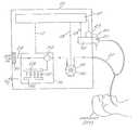
- FIG. 1is a basic schematic diagram of a preferred ventilator system of the present invention incorporating, a) a rotary compressor ventilator device, b) an optional air-oxygen blending apparatus; and c) a controllable exhalation valve, and d) a programmable controller or central processing unit (CPU) which is operative to control and coordinate the functioning of the ventilator, oxygen blending apparatus and exhalation valve.
- a rotary compressor ventilator devicea rotary compressor ventilator device
- an optional air-oxygen blending apparatusand c) a controllable exhalation valve
- a controllable exhalation valveand d) a programmable controller or central processing unit (CPU) which is operative to control and coordinate the functioning of the ventilator, oxygen blending apparatus and exhalation valve.
- CPUcentral processing unit
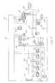
- FIG. 2is a detailed schematic diagram of a ventilator system of the present invention.
- FIG. 3is a front view of the control panel of a preferred ventilator system of the present invention.
- FIG. 4is a perspective view of a preferred drag compressor apparatus which may be incorporated into the ventilator system of the present invention.
- FIG. 5is a longitudinal sectional view through line 5 — 5 of FIG. 4 .
- FIG. 6is an enlarged view of a segment of FIG. 5 .
- FIG. 7is an enlarged view of a segment of FIG. 6 .
- FIG. 8is an elevational view of a preferred drag compressor component of a mechanical ventilator device of the present invention.
- FIG. 9is a perspective view of the drag compressor component of FIG. 8 .
- FIG. 10is an enlarged view of a segment of FIG. 9 .
- FIG. 11 ais a longitudinal sectional view of a preferred exhalation valve of the present invention.
- FIG. 11 bis a perspective view of the preferred spider bobbin component of the exhalation valve shown in FIG. 11 a.
- FIG. 11 cis an exploded perspective view of a portion of the exhalation valve of FIG. 11 a.
- FIG. 11 dis a perspective view of a portion of the exhalation valve shown in FIG. 11 c.
- FIG. 11 eis an exploded perspective view of the preferred flow restricting flapper component of the exhalation valve shown in FIGS. 11 a - 11 d.
- FIG. 12is a graphic example of flow vs. speed vs. pressure data generated for a preferred exhalation valve of the present invention, accompanied by an exhalation valve characterization algorithm computed therefrom.
- the mechanical ventilation system 10 of the present inventiongenerally comprises a) a programmable microprocessor controller 12 , b) a ventilator device 14 , c) an optional oxygen blending apparatus 16 and d) an exhalation valve apparatus 18 .
- a programmable microprocessor controller 12a programmable microprocessor controller 12
- a ventilator device 14a ventilator device 14
- an optional oxygen blending apparatus 16a ventilator device 14
- an exhalation valve apparatus 18which is preferably implemented as a portable, battery powered system.
- the ventilator device 14incorporates a rotating drag compressor 30 which is driven by an electric motor 102 .
- a bladed rotor within the compressor 30will undergo rotation for specifically controlled periods of time and/or, within specifically controlled parameters, so as to provide inspiratory gas flow through line 22 to the patient PT.
- the controller 12comprises a programmable microprocessor which is electrically interfaced a) to the ventilator device 14 by way of control line 13 , b) to the optional oxygen blending apparatus 16 by way of control line 17 , and c) to the exhalation valve 18 by way of control line 19 and also by RF communication between flow transducer transponder ( 21 ) and transmitter/receiver ( 23 ).
- a programmable microprocessorwhich is electrically interfaced a) to the ventilator device 14 by way of control line 13 , b) to the optional oxygen blending apparatus 16 by way of control line 17 , and c) to the exhalation valve 18 by way of control line 19 and also by RF communication between flow transducer transponder ( 21 ) and transmitter/receiver ( 23 ).
- Preferably incorporated into the exhalation valve 18as will be described in more detail infra.
- the controller 12is preferably programmed to utilize selected parameters (e.g., time, flow rate, tidal volume (V t ), airway pressure, spontaneous breath initiation, etc.) for triggering, limiting and cycling the inspiratory flow in accordance with the selected ventilatory mode or breath type.
- selected parameterse.g., time, flow rate, tidal volume (V t ), airway pressure, spontaneous breath initiation, etc.
- exhalation valve 18At the end of each inspiratory flow cycle, the patient PT is permitted to exhale through exhalation valve 18 .
- the flow rate or pressure of the expiratory flow through exhalation valve 18is controlled by varying the degree of flow restriction within the exhalation valve 18 , in response to control signals received through line 19 from controller 12 . This enables the exhalation valve 18 to be utilized to create a selected expiratory back pressure (e.g., CPAP, PEEP).
- a selected expiratory back pressuree.g., CPAP, PEEP
- Optional oxygen blending apparatus 16may be utilized to enrich the oxygen content of the inspiratory gas flow provided by the drag compressor ventilator device 14 .
- the preferred oxygen blending apparatus 16comprises a plurality of (preferably five (5)) solenoid valves 52 , each having a specific sized flow restricting orifice.
- the solenoid valves 52are arranged in parallel between an oxygen inflow manifold 26 and an oxygen outflow manifold 28 .
- the controller 12is programmed to open and close the individual solenoid valves 52 for specific periods of time so as to provide a metered flow of oxygen through oxygen outflow manifold 28 and into accumulator 54 .
- Ambient airis drawn through conduit 24 and filter 50 , into accumulator 54 , where the ambient air combines with the metered inflow of oxygen to provide an oxygen-enriched inspiratory flow containing a prescribed oxygen concentration (FIO 2 ).
- FIO 2prescribed oxygen concentration
- the presently preferred embodiment of the system 10will operate when supplied with voltage input within the range of 85-264 VAC at 50/60 Hz.
- An AC power cordis preferably connectable to the system 10 to provide AC power input.
- the system 10preferably includes an internal battery capable of providing at least 15 minutes, and preferably 30 minutes, of operation. During internal battery operation, some non-essential displays may be dimmed or disabled by the controller 12 .
- the internal batteryis preferably capable of being recharged by AC power input provided through the AC power cable, or by a separate battery charger.
- the internal batteryis preferably capable of being fully charged, from a no charged state, within 24 hours.
- the internal battery charge light 306 shown on the panel of the preferred controller 12 amay additionally flash if desired during charging of the internal battery.
- the systemmay include an external battery or battery set capable of providing at least 2 hours of operation, and preferably capable of providing 4 to 8 hours of operation. During external battery use, some non-essential displays may be dimmed or disabled by the controller 12 .
- the battery or battery setis preferably capable of being recharged by delivery of AC power through the AC power cable, or by a separate battery charger. It is preferable that the external battery or battery set be capable of being fully charged, from a no charged state within 24 to 48 hours.
- the external battery charge light 310 on the panel of the preferred controller 12 amay additionally flash if desired during charging of the external battery or battery set.
- controller 12 of the ventilator system 10 of the present inventionwill vary in complexity, depending on the specific capabilities of the system 10 , and whether or not the optional oxygen blending apparatus 16 is incorporated.
- FIG. 3shows the control panel of a preferred controller apparatus 12 a which is usable in connection with a relatively complex embodiment of the ventilatory system 10 , incorporating the optional oxygen blending apparatus 16 .
- the ventilator system 10incorporates a stand by/off switch (not shown) which turns the main power on or off.
- a group of indicator lights 300are provided on the face panel of the controller 12 a , and are more fully described herebelow under the heading “monitors”.
- the panel indicator lightsinclude an “on” indicator 302 which becomes illuminated when the ventilator is turned on.
- An AC power low/fail indicator light 304activates when the AC power cord is present and the voltage is out of a specified operating range.
- the controller 12 aUpon sensing low or faulty AC power, the controller 12 a will automatically switch the ventilator 14 to internal battery power. The ventilator will continue to operate on internal battery power until such time as power in the internal battery reaches a minimum level. When the power in the internal battery reaches a minimum level, the controller 12 a will cause the internal battery light and/or audible alarm 308 to signal that the internal battery is near depletion.
- a separate external battery light and/or audible alarm 312is also provided.
- the external battery light and/or audible alarmwill activate when the external battery is in use, and has a battery voltage which is out of the acceptable operation range. During this condition, the controller 12 a will cause all nonessential displays and indicators to shut down.
- any internal or external batteries connected to the ventilatorwill be charged by the incoming AC current.
- Internal battery charge indicator light 306 and external battery charge indicator light 306 and external battery charged indicator light 310are provided, and will blink or otherwise indicate charging of the batteries when such condition exists.
- a mode select module 320incorporates plural, preferably five (5) mode select buttons 322 , 324 , 326 , 328 , 330 .
- Mode select button 322sets the system 10 for Assist Control (a/c).
- Mode select button 324sets the system 10 for Synchronized Intermittent Mandatory Ventilation (SIV).
- Mode select button 326sets the system for Continuous Positive Airway Pressure (CPAP).
- CPAPContinuous Positive Airway Pressure
- Spare mode select buttons 328 , 330are provided to permit the controller 12 a to be programmed for additional specific ventilation modes such as volume assured pressure support (VAPS) or proportional assist ventilation.
- VAPSvolume assured pressure support
- select buttons 328 , 330may be correspondingly labeled and utilized to set the ventilator 14 to deliver such subsequently programmed ventilation modes.
- a digital tidal volume display 332with corresponding tidal volume setting button 332 a are provided.
- value setting knob 300may be utilized to dial in a selected tidal volume.
- the tidal volume display 332will then provide a digital display of the currently selected tidal volume value.
- the typical range of settable tidal volumesis 25 ml-2000 ml.
- a digital breath rate display 334with corresponding breath rate setting button 334 a is provided.
- breath rate setting button 334 aWhen breath rate setting button 334 a is depressed, value setting knob 300 may be utilized to dial in the desired breath rate. Breath rate display 334 will thereafter display the currently selected breath rate.
- the typical rage of selectable breath ratesis 0 to 80 breaths per minute.
- a digital peak flow display 336and corresponding peak flow setting button 336 a are provided.
- value setting knob 300may be utilized to dial in the desired peak flow.
- the peak flow display 336will, thereafter, provide a digital display of the currently selected peak flow.
- the typical range of peak flow settingsis 10 to 140 liters per minute.
- a flow sensitivity digital display 338and corresponding flow sensitivity setting button 338 a are provided.
- value setting knob 300may be utilized to dial in the desired flow sensitivity setting.
- the flow sensitivity setting display 338will, thereafter, provide a digital display of the currently selected flow sensitivity setting.
- the flow sensitivity settingdetermines the trigger level for initiation of volume and pressure-controlled assist breaths or pressure support breaths.
- Triggeringoccurs when the patient airway flow exceeds the sensitivity setting.
- the typical range of selectable flow sensitivity settingsis from one to ten liters per minute, or off.
- a fail safe featuremay be incorporated whereby, if the patients flow demand does not exceed the flow sensitivity setting, but the airway pressure drops more than 5 cmH 2 O below the set PEEP level, and inspiratory cycle will be initiated and a breath will be delivered based on current mode and control settings.
- a PEEP/CPAP digital display 340with corresponding PEEP/CPAP setting button 340 a are provided.
- PEEP/CPAP setting button 340 aWhen PEEP/CPAP setting button 340 a is depressed, the value setting knob 300 may be utilized to dial in the desired PEEP/CPAP setting.
- the current PEEP/CPAP settingsets the level of pressure in the patient circuit that is maintained between the end of inspiration and the start of the next inspiration. It is also known as the “baseline”pressure.
- the preferred range of PEEP/CPAP settingis 0 to 50 cmH 2 O.
- a pressure support digital display 342and corresponding pressure support setting button 342 a , are provided.
- pressure support setting button 142 aWhen pressure support setting button 142 a is depressed, value setting knob 300 may be utilized to dial in the desired pressure support setting.
- the pressure support settingdetermines the inspiratory patient circuit pressure during a pressure support breath. This control sets the pressure support level above the baseline setting established by the PEEP/CPAP setting. The total delivered pressure equals the PEEP or CPAP value+pressure support.
- the typical range of pressure support settingsis from 1 to 60 centimeters of water (cmH 2 O), or off.
- An FiO 2 digital display 348and corresponding FiO 2 setting button 348 a , are provided.
- the value setting knob. 300may be utilized to dial in the desired fractional percentage of oxygen in the air/oxygen gas mixture that is delivered to the patient PT and used for the bias flow.
- the controller 12will issue control signals to the oxygen blending apparatus 16 to effect the preset FiO 2 .
- settable FiO 2is between 0.21 and 1.0 (i.e., 21-100 percent oxygen)
- a pressure control digital display 350and corresponding pressure control setting button 350 a are provided.
- the pressure control setting button 350 aWhen the pressure control setting button 350 a is depressed, the value setting knob 300 may be utilized to dial in the desired pressure control value.
- the pressure control settingenables the system to be utilized for pressure control ventilation, and determines the inspiratory pressure level during delivery of each pressure control breath.
- the pressure control settingsets the pressure level above any PEEP.
- the range of possible pressure control settingsbe from 1 to 100 cmH 2 O.
- An optional inspiratory time digital display 352 , and corresponding inspiratory time setting button 352 amay be provided.
- the value setting of 300may be utilized to dial in the desired inspiratory time.
- the set inspiratory timeis the time period for the inspiratory phase of a pressure control breath.
- this inspiratory time settingis normally usable for pressure control ventilation.
- the range of settable inspiratory timesbeing from 0.3 to 10.0 seconds.
- Additional digital displays 344 , 346 , 354 , 356 and corresponding setting buttons 344 a , 346 a , 354 a , 356 aare provided to permit-the controller 12 to be subsequently programmed or expanded to receive and display additional control settings beyond those which have been described hereabove.
- a sigh on/off button 360is provided. When sigh on/off button 360 is depressed, the controller 12 will cause the ventilator 14 to deliver a sigh breath.
- a sigh breathis a volume-controlled, mandatory breath that is usually equal to 1.5 times the current tidal volume setting shown on tidal volume setting display 332 .
- the sigh breathis delivered according to the current peak flow setting shown on peak flow setting display 336 .
- the inspiratory phase of the sigh breathis preferably limited to a maximum of 5.5 seconds.
- the breath periodis automatically increased by a factor of 1.5.
- the sigh breath functionis available during all ventilation modes.
- the sigh breath button 360includes a visual indicator light 360 a which illuminates when the sigh on/off button 360 is depressed and the sigh/breath function is active.
- a manual breath button 362is also provided. Upon depression of the manual breath button 362 , the controller 12 will cause the ventilator 14 to deliver a single volume-controlled or pressure-control breath in accordance with the associated volume and/or pressure control settings. An indicator light 362 a will illuminate briefly when manual breath button 362 is depressed.
- a remote alarm on/off control button 364is provided to enable or disable the remote alarm.
- indicator light 364 awill illuminate.
- the remote alarm on/off button 364is depressed, the remote alarm will be enabled.
- alarm conditionswill transmit via hard wire or radio frequency (wireless) to a remote alarm which may be mounted on the outside of a patients room so as to signal attendants outside of the room, when an alarm condition exists.
- the controller 12includes a square flow wave form activation button 366 and a decelerating taper flow wave form actuation button 368 .
- indicator light 366 aWhen the square flow wave form actuation button 366 is depressed, indicator light 366 a will illuminate, and the ventilator will deliver inspiratory flow at a constant rate according to the peak flow setting, as input and shown on peak flow display 336 .
- indicator light 368 aWhen the decelerating paper wave form actuation button 368 is depressed, indicator light 368 a will illuminate, and the ventilator will deliver an inspiratory flow which initially increases to the peak flow setting, as input and shown on peak flow display 336 , then such inspiratory flow will decelerate to 50 percent of the peak flow setting at the end of the inspiratory phase.
- An inspiratory hold actuation button 370is provided, to enable the operator to hold the patient at an elevated pressure following inspiration, so that breath mechanics can be calculated.
- the length of the delay periodis determined by the period of time during which the inspiratory hold button 370 remains depressed, with a maximum limit applied.
- the controller 12also includes an expiratory hold actuation button 372 , which enables the ventilator to calculate auto PEEP.
- an expiratory hold actuation button 372enables the ventilator to calculate auto PEEP.
- the turbine 30 operationis halted and the exhalation valve 18 remains closed.
- the difference between the end expiratory pressure, as measured at the end of the expiratory hold period, minus the airway pressure reading recorded at the beginning of the expiratory hold period,will be displayed on monitor window 384 .
- the preferred controller 12also incorporates a maximal inspiratory pressure test button 374 , to enable the operator to initiate a maximal inspiratory pressure (MIP) test maneuver. This maneuver causes the ventilator to stop all flow to or from the patient. The patient inspiratory effort is then monitored and displayed as MIP/NIF in the monitor window 384 .
- MIPmaximal inspiratory pressure
- the controller 12 aincludes a 100% O 2 actuation button 376 which, when depressed, will cause indicator light 376 a to illuminate and will cause the system 10 to deliver an FiO 2 of 1.00 (i.e., 100% oxygen) to the patient for a period of three (3) minutes regardless of the current FiO 2 setting and/or breath type setting.
- a 100% O 2 actuation button 376which, when depressed, will cause indicator light 376 a to illuminate and will cause the system 10 to deliver an FiO 2 of 1.00 (i.e., 100% oxygen) to the patient for a period of three (3) minutes regardless of the current FiO 2 setting and/or breath type setting.
- This 100% O 2 featureenables the operator to selectively deliver 100% oxygen to the patient PT for a three minute period to hyperoxygenate the patient PT prior to disconnection of the patient from the ventilator circuit for purposes of suctioning, or for other clinical reasons.
- An additional control actuation button 378is provided to enable the controller 12 a to be subsequently programmed to perform additional control actuation functions beyond those described hereabove.
- An AC power indicator light 304is provided in the face panel of the controller 12 to indicate when sufficient AC power is available and the standby/off switch (not shown) is in the standby position.
- An internal battery status indicator light 308is provided on the panel of the controller 12 , and will indicate battery charge level according to predetermined color signals.
- a separate internal battery charge indicator light 306may be provided, and will indicate charging status according to predetermined color signals.
- An external battery status indicator light 312is provided on the panel of the controller 12 , and will indicate battery charge level according to predetermined color signals.
- a separate external battery charge indicator light 310may be provided, and will indicate charging status according to predetermined color signals.
- the display panel of the controller 12includes a real time airway pressure bar graph display 380 .
- a green indicator barwill appear on the airway pressure bar graph display 380 to indicate the real time airway pressure at all times. Red indicators will appear on the airway pressure bar graph to indicate high and low peak pressure alarm setting, as more fully described herebelow under the heading “Alarms”.
- An amber colored indicatorwill appear on the airway pressure bar graph display 380 to indicate the current PEEP/CPAP setting, Pressure Support setting and/or Pressure Control setting.
- a patient effort indicator light 382is located near the airway pressure bar graph display 380 , and will illuminate to indicate the occurrence of a patient-initiated breath, including all spontaneous, assist or pressure support breaths.
- the panel of the controller 12preferably includes a digital monitor display 384 and an accompanying monitor select button 386 .
- the controller 12is programmed to display various monitored parameters. Each time the monitor select button 386 is depressed, the monitored parameters displayed on monitor display 384 will change.
- the individual parametersmay include: exhaled tidal volume, i.e., ratio, mean airway pressure, PEEP, peak inspiratory pressure, total breath rate, total minute ventilation.
- a display power saving featuremay be incorporated, whereby the controller 12 will automatically cause the monitor display 384 to become non-illuminated after a predetermined display period when the system 10 is operating solely on internal or external battery power. Each time the monitor select button 386 is depressed, the display 384 will illuminate for a predetermined period of time only, and then will become non-illuminated. This feature will enable the system 10 to conserve power when the system 10 is being operated solely on internal or external battery power.
- controller 12may be programmed to cause the monitor display 384 to display a special or different group of parameters during a specific operator-initiated maneuver.
- special parameter groupswhich may be displayed during a specific maneuver include the following:
- the preferred controller 12may be programmed to received operator input of one or more limiting parameters, and to provide audible and/or visual alarm indications when such limiting parameters have been, or are about to be, exceeded.
- the visual alarm indicatorsmay comprise steady and or flashing lights which appear on the control panel of the preferred controller 12 a.
- the audible alarm componentswill preferably comprise electronic buzzers or beepers which will emit sound discernable by the human ear for a preselected period (e.g., 3 seconds).
- a preselected periode.g. 3 seconds
- the audible portion of any alarmmay be volitionally muted or deactuated by the operator.
- controller 12be programmed to automatically reset each alarm if the current ventilation conditions do not fall outside of the preset alarm limits.
- the preferred controller 12includes, on its face panel, a high pressure digital display 390 and a corresponding high pressure alarm limit setting button 390 a .
- value setting knob 300may be utilized to dial in a desired high pressure alarm limit value. Such high pressure alarm limit value will then be displayed on high pressure alarm limit display 390 .
- the currently set high pressure alarm limitwill establish the maximum peak inspiratory pressure for all breath types.
- audible and visual alarmswill be actuated by the controller 12 and the controller will immediately cause the system 10 to cycle to expiratory mode, thereby allowing the airway pressure to return to the baseline bias flow level and along the exhalation valve 18 to regulate pressure at any currently-set peep level.
- the controller 12will be programmed to automatically adjust the high pressure alarm limit value by a factor of 1.5X during the delivery of a sigh breath, provided that such does not result in the high pressure limit value exceeding 140 cmH 2 O.
- the controller 12is preferably programmed not to exceed a high pressure limit setting of 140 cmH 2 O, even during delivery of a sigh breath.
- a low peak airway pressure limit display 392and corresponding low peak pressure limit setting button 392 a , are also provided.
- value setting knob 300may be utilized to dial in a desired low peak airway pressure alarm limit value. Such low peak pressure alarm limit value will then be displayed in the low peak pressure display 392 .
- Audible and/or visual alarmswill be activated if the monitored airway pressure fails to exceed the low peak pressure alarm limit setting during the inspiratory phase of a machine-cycled mandatory or assist breath.
- the controller 12is preferably preprogrammed to deactivate the low peak airway pressure alarm during spontaneous, CPAP and pressure support breathing.
- the range of low peak pressure settingswill preferably be from 2 to 140 cmH 2 O.
- a low minute volume display 394and corresponding low minute volume setting button 394 a are provided.
- value setting knob 300may be used to dial in the desired low minute volume alarm setting.
- the currently-set low minute volume alarm settingwill be displayed in digital display 394 .
- the controller 12will be programmed to calculate the current exhaled minute volume based on information received from the exhalation valve differential pressure transducer 70 , and to trigger audible and/or visual alarms when the exhaled minute volume becomes less than or equal to the currently set low minute volume alarm limit. This alarm is active for all breath types.
- the typical range of settable low minute volume alarm limitsis from 0 to 99.9 liters/min.
- the controller 12may be programmed to trigger auditory and/or visual apnea alarms when the period between initiation of inspiratory phases exceeds 20 seconds.
- the controller 12is preferably also programmed to initiate back-up machine ventilation when an apnea alarm condition exists.
- the controller 12is preferably programmed not to permit volitional silencing of the apnea alarm until the apnea condition has been corrected.
- Spare alarm limit displays 396 , 398 , and corresponding spare alarm limit setting buttons 396 a and 398 aare provided, to permit the controller 12 to be subsequently expanded or programmed to receive operator input of additional limiting parameters, and to provide auditory and/or visual alarms when such limiting parameters have been exceeded.
- a separate ventilator inoperative light indicator 400is provided on the face panel of the controller 12 .
- the controller 12is programmed to cause the ventilator inoperative light to illuminate when predetermined “ventilatory inoperative” conditions exist.
- the controller 12is preferably programmed to activate visual and/or auditory alarms when an AC power cord is connected to the system 10 and the voltage received by the system 10 is outside of a specified operating range.
- the controller 12is preferably also programmed to automatically switch the system 10 to internal battery power under this condition.
- the AC power low/fail alarmcan be silenced, and will remain silenced, until such time as the internal low battery alarm 208 becomes actuated, indicating that the internal battery has become depleted.
- the controller 12may be programmed to actuate a visual and or auditory alarm when an external or internal battery is in use, and the battery voltage is outside of an acceptable operating range.
- the controller 12may be programmed to provide auditory and/or visual alarms when the oxygen pressure delivered to the system 10 is above or below predetermined limits.
- the system 10includes a mechanical variable pressure relief valve 64 , to relieve any over pressurization of the patient circuit.
- the range of settable over pressure relief limit valuesmay be between 0 to 140 cmH 2 O.
- the preferred controller 12may be programmed to perform a self-testing function each time the ventilator is powered up. Such self testing function will preferably verify proper functioning of internal components such as microprocessors, memory, transducers and pneumatic control circuits. Such self testing function will also preferably verify that electronic sub-systems are functioning correctly, and are capable of detecting error conditions relating to microprocessor electronics.
- the controller 12may be programmed to allow a qualified operator who enters a given key sequence, to access trouble shooting and calibration information.
- the key operatormay induce the controller to display, on the monitor display 384 , information such as the following:
- controller 12may be programmed to allow a qualified operator who entered a given key sequence, to access a user preference and set up menu.
- menumay include a monitory display 384 , of information such as the following:
- the user preference and set up menu functionmay also be accessible during operation of the system 10 .
- the portable system 10 ventilator of the present inventionpreferably incorporates a rotary drag compressor apparatus 30 comprising a dual-sided, multi-bladed rotor 104 disposed within a rigid compressor housing 106 .
- An inflow/outflow manifold 108is formed integrally with the compressor housing 106 , and incorporates two (2) inflow passageways 112 and two (2) outflow passageways 110 for channeling gas flow into and out of the compressor apparatus 30 .
- An electric motor 102such as a 0.8 peak horsepower, 40 volt D.C. motor, is preferably mounted integrally within the compressor housing 106 .
- the motor 102may be encased or housed in an encasement or housing which is separate from the compressor housing 106 .
- the motor shaft 114extends transversely into a bore 116 formed in the central hub 118 of rotor 104 .
- the bore 116 of the central hub 118 of rotor 104may include a rectangular key-way 121 formed on-one side thereof and the motor shaft 114 may include a corresponding elongate rectangular lug formed thereon.
- the rectangular lug of the motor shaft 114inserts within and frictionally engages the key-way 121 of the rotor hub 118 , thereby preventing the motor shaft 114 from rotationally slipping or turning within the bore 116 of the rotor hub 118 .
- various alternative mounting structuresother than the lug and keyway 121 shown in FIGS. 8-9, may be utilized to rotatably mount the motor shaft 114 to the rotor 104 .
- the rotor hub 118is preferably formed having a concave configuration, as shown in FIG. 5 .
- Such concave configurationserves to impart structural integrity and strength to the rotor 104 , without significantly increasing the mass of the rotor 104 as would result from the formation of additional strengthening ribs or bosses on the rotor hub 118 .
- a first annular trough 120extends about the periphery of the front side of the rotor 104
- a second annular trough 122extends about the periphery of the backside of the rotor 104 .
- a multiplicity of rotor blade-receiving slots 126are formed angularly, at evenly spaced intervals about the inner surfaces of the first 120 and second 122 annular troughs.
- Rotor blades 128are mounted at spaced-apart locations around each annular trough 120 , 122 such that the radial peripheral edge 127 of each blade 128 is inserted into and resides within a corresponding blade receiving slot 126 and the leading edge 129 of each blade traverses across the open annular trough 120 or 122 , as shown.
- Each blade 128is affixed by adhesive, or other suitable means, to the body of the rotor 104 .
- the blades 128are located in axially aligned positions, i.e., non-staggered directly opposite positions on opposite sides of the rotor 104 so as to promote even pressure balance and symmetrical weight distribution within the rotor 104 .
- the rotor 104is rotatably mounted within the compressor housing 106 such that the first 120 and second 122 annular cavities are in alignment with the inflow 110 and outflow 112 channels, as shown.
- the body of the rotor 104is preferably constructed of light weight material such as aluminum, and the individual blades 128 of the rotor 104 are preferably constructed of light weight material such as glass-filled epoxy.
- a suitable adhesivesuch as epoxy may be utilized to bond the radial edges of the blades 128 within their corresponding blade-receiving slots 126 .
- rotor and bladesintegrally, as by way of a molding process whereby metal (e.g., aluminum), polymer or composite materials are molded to form the blades 128 and rotor 104 as a unitary structure.
- metale.g., aluminum
- polymer or composite materialsare molded to form the blades 128 and rotor 104 as a unitary structure.
- each individual blade 128will preferably be disposed at an angle of attack A, relative to a flat transverse plane TP projected transversely through the body of the rotor 104 , between the first annular trough 120 on the front side of the rotor 104 , and the second annular trough 122 on the backside of the rotor 104 .
- the angle Ais preferably in the range of 30-60 degrees and, in the preferred embodiment shown in FIGS. 8-10 is 55 degrees. Such angle A is selected to provide optimal flow-generating efficiency of the rotor 104 .
- each individual compressor 30will typically exhibit some individual variation of flow output as a function of the rotational speed and differential pressure of that compressor 30 .
- the controller 12will be correspondingly programmed to perform the necessary interpolative mathematical steps to obtain instantaneous flow, speed or pressure determinations as a function of any two such variables, for the particular compressor 30 .
- the second wayis to experimentally generate a series of flow, speed and pressure data points over a range of normal operating rotor speeds, and to subsequently derive a unique speed vs. flow vs. pressure equation to characterize each individual compressor 30 .
- Such individual characterization equationis then programmed into, or otherwise provided to, the controller 12 and the controller 12 is programmed to utilize such equation to compute precise, instantaneous speed, flow rate and pressure control signals for controlling the individual compressor 30 in use.
- An example of such graphical speed vs. flow rate vs. pressure data, and a characterization equation derived therefrom,is shown in FIG. 12 .
- controller 12which has the capability to receive and process such a characterization equation as shown in (FIG. 12) for controlling the compressor 30 would require substantial expense and size enlargement of the controller 12 . Accordingly, given the present state of the art, it is most desirable to utilize the former of the two above-described methods—that is, providing a database of discrete flow, speed and pressure values and programming of the controller 12 to perform the necessary mathematical interpolations of the provided data points for maintaining compressor-specific control of the pressure, flow rate and/or volume of gas provided in each inspiratory phase at the ventilation cycle.
- the experimentally generated database of discreet flow, speed and pressure valvesmay be encoded onto an EPROM or any other suitable database storage device.
- Such EPROM or other database storage devicemay be located on or within the compressor itself and communicated to the controller 12 via appropriate circuitry. Alternatively, such EPROM or database storage device may be installed directly into the controller 12 at the time the particular compressor 30 is installed within the ventilator device 14 .
- the controlled inspiratory flow generated by the rotary drag compressor 30exists from the compressor outlet 34 and through line 22 to the patient PT.
- an output silencer 60such as a hollow chamber having a quantity of muffling material formed therearound, is preferably positioned on inspiratory flow line 22 to reduce the sound generated by the ventilator 14 during operation.
- An inspiration occlusion valve 62is additionally preferably mounted on inspiratory flow line 22 to accomplish operator controlled stoppage of the inspiratory flow as required during performance of a maximal inspiratory force maneuver.
- a pressure relief valve 64is connected to inspiratory flow line 22 to provide a safeguard against delivering excessive inspiratory pressure to the patient PT.
- the pressure relief valve 64may be manually set to the desired limit pressure, by the operator.
- the rotary drag compressor ventilator 14operates by periodic rotating of the rotor 130 within the compressor 30 to generate the desired inspiratory gas flow through line 22 . It is desirable that the rotor 130 be accelerated and decelerated as rapidly as possible. Such rapid acceleration/deceleration is facilitated by a reduction in inertial effects as a result of the above-described low mass construction of the rotor 104 .
- the speed and time of rotation of the rotor 104is controlled by the controller 12 based on the variables and/or parameters which have been selected for triggering, limiting and terminating the inspiratory phase.
- the precise flow, volume or pressure delivered through the inspiratory line 22is controlled by the controller based on the EPROM-stored compressor characterization data received by the controller, as well as periodic or continuous monitoring of the rotational speed of the rotor 104 and the change in pressure ( ⁇ p ) between the inlet side 32 and outlet side 34 of the compressor 30 as monitored by the differential pressure transducer 36 .
- the controller 12is programmed to deliver breaths by either of two available closed loop algorithms; volume or pressure.
- the controller 12Prior to Volume breath initiation, the controller 12 generates a predefined command waveform of flow vs time.
- the waveformis generated using the current Flow, Volume and Waveform input settings from the front panel. Since the mathematical integral of flow over time is equal to the volume delivered, the controller can determine the appropriate inspiratory time.
- the controlleruses closed loop control techniques well known in the art to drive the compressor, periodically read the compressor differential pressure and rotational speed, and then calls upon the specific stored compressor characterization data to arrive at the actual flow rate. Once actual flow rate is known, it is compared or “fed back” to the current commanded flow, and a resulting error is derived. The error is then processed through a control algorithm, and the compressor speed is adjusted accordingly to deliver the desired flow rate. This process is repeated continuously until the inspiration is complete.
- Pressure breathsinclude several breath types such as Pressure Support or Pressure Control.
- the controllercommands the compressor to provide flow as required to achieve a pressure as input from the front panel.
- the controlleruses closed loop control techniques well known in the art to drive the compressor 30 and to achieve the desired patient airway pressure.
- the controllerperiodically reads the actual airway pressure. Once actual pressure is known, it is “fed back” and compared to the current commanded pressure, and a resulting error is derived. The error is then processed through a control algorithm, and the compressor speed is adjusted accordingly to deliver the desired pressure. This process is repeated continuously until the inspiration is complete.
- the controllerwill signal the compressor motor 102 to stop or decelerate to a baseline level, thereby cycling the ventilator in to the expiratory phase.
- the controller 12may be additionally programmed or equipped to control the operation of the oxygen blending apparatus 16 to mix a prescribed amount of oxygen with ambient air drawn through air intake 24 , thereby providing an inspiratory flow having a prescribed oxygen content (FiO 2 ) between 21%-100%.
- a prescribed oxygen contentFOG 2
- the preferred oxygen blending apparatus 16comprises an air inlet line 24 which opens into a hollow vessel or accumulator 54 .
- Oxygen inlet line 26is connected to a pressurized source of oxygen and leads, via a manifold to a series of solenoid valves 52 .
- solenoid valves 52a series of solenoid valves 52 .
- Each such separate solenoid valve 52 a - 52 ehas a specific (usually differing) sized flow restricting orifice formed therein so that each such solenoid valve 52 a - 52 e will permit differing amounts of oxygen to pass into accumulator 54 , per unit of time during which each such solenoid valve 52 a - 52 e is maintained in an open position.
- the controller 12is preprogrammed to determine the specific period(s) of time each solenoid valve 52 a - 52 e must remain open to provide the necessary amount of oxygen to accumulator 54 to result in the prescribed oxygen concentration (FiO 2).
- the rotational velocity of the rotor 104 and differential pressure across the inflow/outflow manifold 108are measured by the controller 12 and from this data the controller 12 is able to determine the flow of gas through the compressor 30 from the accumulator 54 .
- the controller 12integrates the air flow drawn through the compressor 30 to determine the accumulated volume of enriched gas drawn from said accumulator 54 . In order to maintain the flow of gas at the prescribed FiO 2 level, a portion of this removed volume must be replaced in the accumulator 54 with pure oxygen.
- the accumulated volumeis compared to a predetermined trigger volume for each of the solenoids 52 a - 52 e , which in the preferred embodiment, is defined by the equation:
- Trigger Volume(Solenoid Flow*Time*79)/[(FiO 2 ⁇ 21)*2]
- each solenoid that is not currently openis compared.
- the controller 12opens that solenoid 52 for a period of time allowing oxygen to flow from the oxygen inlet line 26 through the solenoid 52 and into the accumulator 54 .
- the controller 12then adjusts the accumulated volume appropriately by subtracting a volume, proportional to the volume of oxygen delivered to the accumulator 54 from the accumulated volume defined by the equation:
- the trigger volume the controller 12 uses to open an individual solenoid 52 a - 52 eis independent for each solenoid 52 and is function of the flow capacity of the particular solenoid 52 a - 52 e , the prescribed FiO 2 level, and the amount of time the solenoid 52 is open.
- the amount of time each solenoid 52 is openis the same for each solenoid 52 , but may vary as a function of oxygen inlet pressure.
- the oxygen blending apparatushas 4 solenoids with flows of 5 lpm, 15 lpm, 40 lpm, and 80 lpm respectively.
- the FiO 2 settingis 60%, thus the trigger volumes for each of the 4 solenoids is 8 ml, 25 ml, 66 ml, and 133 ml respectively.
- a constant oxygen inlet pressureis assumed resulting in an “on” time of 100 ms for the solenoids, a constant compressor flow of 60 lpm, and a period of 1 ms.
- the following tabledescribes the state of the oxygen blending algorithm after various iterations:
- the exhalation valve 18comprises a housing which defines an expiratory flow path therethrough and a valving system for controlling the airway pressure during the expiratory phase of the ventilation cycle.
- the exhalation valve 18shares numerous structural and functional attributes with the exhalation valve described in U.S. Pat. No. 5,127,400 (DeVries et al) entitled Ventilator Exhalation Valve, issued Jul. 7, 1994, the disclosure of which is expressly incorporated herein by reference.
- the exhalation valve assembly 18 of the present inventionadditionally incorporates an exhalation flow transducer 230 which serves to monitor exhalation flow from the patient and generates an output signal to the controller 12 . The output signal is then utilized by the controller to determine when patient exhalation has ceased to thereby initiate inspiratory flow to the patient.
- the exhalation flow transducer 230is mounted within the exhalation valve 18 in unique structure to minimize manufacturing inaccuracies. Further, in the preferred embodiment, the particular operational characteristics of the exhalation flow transducer 230 are stored within a memory device which is then communicated to the controller 12 to insure accuracy in flow measurements.
- exhalation flow transducer 230 of the present inventionshares numerous structural and functional attributes with the flow transducer described in the U.S. Pat. No. 4,993,269, issued to Nicolas et al., entitled Variable Orifice Flow Sensing Apparatus, issued on Feb. 19, 1991, the disclosure of which is expressly incorporated herein by reference.
- the exhalation valve 18 of the present inventionis formed having a housing 200 including an exhalation tubing connector 202 formed at a first location thereon and an outflow port 204 formed at a second location thereon.
- An exhalation gas flow passageway 206extends through the interior of the housing 200 such that expiratory gas may flow from the exhalation tubing connector 202 through the exhalation passageway 206 within the interior of the exhalation valve 18 and subsequently passed out of the outflow port 204 .
- annular valve seat 208Midway through the expiratory flow passageway 206 , there is formed an annular valve seat 208 .
- the annular valve seat 208may be disposed in a plane which is parallel to the plane of the flat diaphragm 210 or alternatively, as in the embodiment shown, the annular valve seat 208 may be slightly angled or tapered relative to the plane in which the flat diaphragm 210 is positioned. Such angling or tapering of the valve seat 208 facilitates seating of the diaphragm 210 on the valve seat 208 without flutter or bouncing of the diaphragm 210 .
- the elastomeric disc or diaphragm 210is configured and constructed to initially contact the farthest extending side of the angled valve seat 208 , and to subsequently settle or conform onto the remainder of the angled valve seat 208 , thereby avoiding the potential for flutter or bouncing which may occur when the diaphragm 210 seats against a flat non-angled valve seat 208 .
- the disc or diaphragm 210is preferably attached to the surrounding rigid housing 200 by way of an annular flexible frenulum 212 .
- Frenulum 212serves to hold the disc or diaphragm 210 in axial alignment with the annular valve seat 208 , while permitting the disc or diaphragm 210 to alternatively move back and forth between a closed position wherein the diaphragm 210 is firmly seated against the valve seat 208 (FIG. 11 a ) and a fully open position wherein the disc or diaphragm 210 is retracted rearwardly into the adjacent cavity within the housing 200 thereby providing an unrestricted flow path 206 through which expiratory gas may flow.
- a pressure distributing plate 214is mounted on the backside of the diaphragm 210 .
- a hollow actuation shaft 216is mounted within the housing 200 and is axially reciprocal back and forth to control the position of the diaphragm 210 relative the valve seat 208 .
- a bulbous tip member 218is mounted on the distal end of a hollow actuation shaft 216 .
- a corresponding pressure distribution plate 214is mounted on the back of the diaphragm 210 . Forward movement of the actuation shaft 216 causes the bulbous tip member 218 to exert forward pressure against the plate 214 thereby forcing the diaphragm 210 toward its closed position.
- the diaphragm 210When the actuation shaft 216 is in a fully forward position, the diaphragm 210 will be held in firm abutment against the annular valve seat 208 thereby terminating flow through the passage 206 . Conversely when the actuation shaft 216 is retracted, the diaphragm 210 moves away from the valve seat 208 thereby allowing flow through the passageway 206 thereby allowing flow through the passageway 206 .
- the movement of the shaft 216is controlled by way of an electrical induction coil 220 and spider bobbin 222 arrangement.
- the electrical induction coil 220is formed without having an internal support structure typically utilized in induction coils so as to minimize inertial concerns.
- the coil 220is typically formed by winding upon a mandrel and subsequently maintained in this wound configuration by way of application of a suitable binder or varnish.
- the bobbin 222is preferably formed having a cross-beam construction, as shown in FIG. 11 b , to decrease the mass of the bobbin 222 while maintaining its structural integrity.
- the shaft 216is preferably formed from a hollow stainless steel material so as to be relatively strong yet light weight enough for minimizing inertial concerns.
- the bobbin 222is affixed to the distal end of the induction coil 220 and the shaft 216 extends through an aperture formed in the center of the bobbin and is frictionally or otherwise affixed to the bobbin such that the shaft 216 will move back and forth in accordance with the bobbin 222 and coil 220 .
- the coil 220will translate rearwardly into the coil receiving space 226 about the magnet thereby moving the shaft 216 and blunt tip member 218 in the rearward direction and allowing the diaphragm 210 to move in an open position away from the valve seat 208 of the expiratory flow path 206 . With the diaphragm 210 in such open position, expiratory flow from the patient PT may pass through the expiratory flow pathway 206 and out the expiratory port 204 .
- the current into the induction coilmay change direction, thereby causing the induction coil to translate forwardly.
- Such forward translation of the induction coil 220will drive the bobbin 222 , shaft 216 , and bulbous tip member 218 in a forward direction, such that the bulbous tip member 218 will press against the flow distributing plate 214 on the backside of the diaphragm 210 causing the diaphragm to seat against the valve seat 208 .
- the inspiratory phase of the ventilator cyclemay begin and ambient air will be prevented from aspirating or backflowing into the patient circuit through the exhalation port 204 .
- a elastomeric boot 217 or dust barrieris mounted about the distal portion of the hollow actuation shaft 216 , and is configured and constructed to permit the shaft 216 to freely move back and forth between its fully extended closed position and a fully retracted open position while preventing dust or moisture from seeping or passing into the induction coil 220 .
- the housing of the exhalation valve 18includes a frontal portion formed by the housing segments 200 b , 200 c , and 200 d .
- An airway pressure passage 241is provided within the housing portion 200 b , which enables the pressure within the exhalation passageway 206 to be communicated to an airway pressure tubing connector 233 .
- Airway pressure tubing connector 233is connected via tubing to an airway pressure transducer 68 (shown in FIG. 2) which monitors airway pressure and outputs a signal to the controller 12 .
- the controller 12in response of receipt of the pressure signal from pressure transducer 68 increases or decreases the voltage applied to the coil 220 to maintain desired pressure within the exhalation air passage 206 .
- such monitoring of the airway pressureis continuous during operation of the ventilator cycle.
- the exhalation flow transducer 230 of the present inventionis preferably disposed with the exhalation valve housing and serves to monitor exhalation flow from the patient PT. More particular, the exhalation flow transducer 230 , of the present invention preferably incorporates a feedback control system for providing real time monitoring of the patient's actual expiratory flow rate. As best shown in FIGS. 11 a and 11 c , the expiratory flow transducer 230 of the present invention is incorporated within the exhalation flow path 206 within housing segment 200 b .
- the flow transducer 230is preferably formed from a flat sheet of flexible material having a cut out region 406 formed therein.
- a peripheral portion 408 of the flat sheetexists outside of the cut out region 406 and flapper portion 231 is defined within the cut out region 406 .
- Frame members 410 and 412preferably formed of a polymer material, are mounted on opposite sides of the flat sheet so as to exert inward clamping pressure on the peripheral portion 408 of the flat sheet.
- the flapper portion 231 of the flat sheetis thus held in its desired transverse position within the open central aperture 14 a and 14 b of the transducer assembly and such flapper portion 231 is thus capable of flexing downstream in response to exhalation flow.
- a frame member 411is preferably positioned in abutting juxtaposition to the outboard surface of at least one of the frame members 410 , 412 .
- the frame member 411is positioned in abutment with the upper frame member 410 .
- Such frame member 411comprises a metal frame portion 413 and includes an elastomeric cushioning gasket or washer 415 disposed on the lower side thereof.
- a central aperture 14 cis formed in the frame member 411 , such aperture 14 c being of the same configuration, and in axial alignment with central apertures 14 a , 14 b of the upper and lower frame members 410 , 412 .
- Upper and lower abutment shoulders 418 a , 418 bare formed within the exhalation valve housing 200 to frictionally engage and hold the flow transducer assembly 230 in its desired operative position.
- the upper engagement shoulder 418 awill abut against the upper surface of the frame member 411
- the lower abutment shoulder 418 bwill abut against the lower surface of the lower frame member 412 , thereby exerting the desired inward compressive force on the flow transducer assembly 230 .
- the inclusion of the cushioning washer 415serves to evenly distribute clamping pressure about the peripheral portion 408 , thereby minimizing the creation of localized stress within the flow transducer 230 .
- an upstream pressure port 232will be located upstream of the flapper 231
- a downstream pressure port 234will be located downstream of the flapper 231 .
- pressuresmay be concurrently measured through upstream pressure port 232 and downstream pressure port 234 to determine the difference in pressures upstream and downstream of the flapper 231 .
- the flapper portion 231 of the flow transducer 230will deflect or move allowing such expiratory gas flow to pass thereacross, but also creating a moderate flow restriction.
- the flow restriction created by the flow transducer 230results in a pressure differential being developed across the flow transducer 230 .
- Such pressure differentialmay be monitored by pressure ports 232 and 234 disposed on opposite side of the flow transducer 230 (as shown in FIG. 11 a ) which pressure ports are in flow communication by internal passages formed within the housing segment 200 c , 200 b and 200 a to tubing connections 240 and 235 .
- a manifold insert 201may be mounted on the upstream pressure port 232 such that the manifold insert 201 protrudes into the expiratory flowpath 206 , upstream of the flapper 231 .
- a plurality of inlet apertures 201 aare formed around the outer sidewall of the manifold insert 201 , and communicate through a common central passageway with the upstream pressure port 232 , thereby facilitating accurate measurement of the pressure within the expiratory flowpath 206 at that location.
- An exhalation differential pressure transducer 70may be located within the housing or enclosure of the ventilator 10 .
- the exhalation differential pressure transducer 70is connected by way of tubing to the first and third pressure port tubing connectors 240 and 235 so as to continuously measure and provide the controller 12 with the difference between pressure upstream (P 1 ) and pressure downstream (P 2 ) of the flow transducer 230 .
- the difference in pressure determined by the exhalation differential pressure transducer 70is communicated to the controller, and the controller is operatively programmed to calculate the actual flow rate at which expiratory gas is exiting the flow channel 206 .
- the exhalation flow ratemay be utilized by the controller 12 for differing purposes such as triggering of initiation of the next inspiratory cycle.
- each exhalation flow transducer 230provides exceptional accuracy in most situations, the applicant has found that in certain circumstances, it is desirable to eliminate any inaccuracies caused by manufacturing and assembly tolerances.
- the specific operational characteristics of each exhalation flow transducer 230i.e., pressure differential for specific flow rates are measured for calibration purposes and stored on a storage medium contained within the exhalation valve housing 18 .
- this specific characterization and calibration informationis encoded on a radio frequency transponder 203 of the type commercially available under the product name Tiris, manufactured by Texas Instruments, of Austin, Tex.
- the radio-frequency transponder 203 and its associated transmitter/receiver antenna 203 amay be mounted within the exhalation valve housing 200 as shown in FIG. 11 c . Additionally, a radio frequency transmitter/receiver is positioned within the ventilator system 10 , such that upon command of the controller 12 , the calibration and characterization data contained within the transponder 203 is transmitted via radio frequency to the receiver and stored within the controller 12 . Subsequently, the controller 12 utilizes such stored calibration and characterization data to specifically determine expiratory flow rate based upon pressure differential values generated by the differential pressure transducer 70 .
- the ventilator device 14 of the ventilator system 10 of the present inventionincorporates an auto calibration circuit for periodic rezeroing of the system to avoid errors in the tidal volume or inspiratory flow delivered by-the drag compressor 30 .
- the preferred auto calibration circuitcomprises the following components:
- Each of the auto-zero valves 72 , 74 , 76 , . 78 , 80is connected to the controller 12 such that, at selected time intervals during the ventilatory cycle, the controller 12 may signal the auto-zero valves 72 , 74 , 76 , 78 , 80 to open to atmospheric pressure. While the auto-zero valve 72 , 74 , 76 , 78 , 80 are open to atmospheric pressure, the controller 12 may re-zero each of the transducers 36 , 68 , 70 to which the respective auto-zero valve 72 , 74 , 76 , 80 are connected. Such periodic re-zeroing of the pressure transducers 36 , 68 and 70 will correct any baseline (zero) drift which has occurred during operation.
- the basic operation of the ventilator system 10 of the present inventionmay be described.
- the particular ventilatory mode selected by a technicianmay be input to the controller 12 via the input controls upon the display 380 .
- the technicianmust attach the inspiratory and exhalation tubing circuit to the patient PT as illustrated in FIG. 1 .
- the controller 12Prior to initiation of patient ventilation, the controller 12 initiates its auto calibration circuit and system check to insure that all system parameters are within operational specifications. Subsequently, inspiration is initiated wherein the controller 12 rapidly accelerates the drag compressor 30 . During such acceleration, air is drawn through the filter 50 , accumulator 54 and supplied to the patient PT, via line 22 . During such inspiratory phase, the controller 12 monitors the pressure drop across the compressor 30 , via pressure transducer 36 , and the rotational speed of the rotor 104 . This data is then converted to flow by the controller 12 via the turbine characterization table to insure that the proper flow and volume of inspiratory gas is delivered to the patient PT. Additionally, during such inspiratory phase, the exhalation valve 18 is maintained in a closed position.
- the controller 12additionally opens selected ones of the solenoid valve 52 a , 52 b , 52 c , 52 d and 52 e , in timed sequence to deliver a desired volume of oxygen to the accumulator 54 , which is subsequently delivered to the patient PT during inspiratory flow conditions.
- the controller 12When inspiratory flow is desired to be terminated, the controller 12 rapidly stops or decelerates the drag compressor 30 to a basal rotational speed, and the patient is free to exhale through exhalation line 66 and through the exhalation valve 18 .
- the controller 12monitors the exhalation pressure, via pressure transducer 68 connected to the airway passage and adjusts—.the position of the valve relative the valve seat within the exhalation valve 18 to maintain desired airway pressures.
- the controller 12monitors the pressure differential existing across the exhalation flow transducer 230 via exhalation pressure transducer 70 to compute exhaled flow. This exhaled flow is used to compute exhaled volume and to determine a patient trigger.
- the controllerinitiates a subsequent inspiratory flow cycle with subsequent operation of the ventilator system 10 being repeated between inspiratory and exhalation cycles.
- Ventiler 10differing ventilation modes, such as intermittent mandatory ventilation (IMV), synchronized intermittent mandatory ventilation (SMIV) controlled mechanical ventilation (CMV) and assist control ventilation (A/C), are all available modes of operation on the ventilator 10 of the present invention.
- IMVintermittent mandatory ventilation
- SIVsynchronized intermittent mandatory ventilation
- CMVmechanical ventilation
- A/Cassist control ventilation
- machine cycled mandatory breathmachine cycled assist breath
- patient cycled supported breathpatient cycled spontaneous breath
- volume controlled mandatory breathsvolume controlled assist breaths
- pressure controlled breathspressure controlled breaths
- pressure support breathspressure support breaths
- sigh breathsproportional assist ventilation and volume assured pressure support.
Landscapes
- Health & Medical Sciences (AREA)
- Pulmonology (AREA)
- Emergency Medicine (AREA)
- Veterinary Medicine (AREA)
- Anesthesiology (AREA)
- Biomedical Technology (AREA)
- Heart & Thoracic Surgery (AREA)
- Hematology (AREA)
- Life Sciences & Earth Sciences (AREA)
- Animal Behavior & Ethology (AREA)
- General Health & Medical Sciences (AREA)
- Public Health (AREA)
- Engineering & Computer Science (AREA)
- Fluid Mechanics (AREA)
- General Physics & Mathematics (AREA)
- Physics & Mathematics (AREA)
- Measurement Of The Respiration, Hearing Ability, Form, And Blood Characteristics Of Living Organisms (AREA)
- Respiratory Apparatuses And Protective Means (AREA)
- Pharmaceuticals Containing Other Organic And Inorganic Compounds (AREA)
- Compressors, Vaccum Pumps And Other Relevant Systems (AREA)
- Control Of Positive-Displacement Air Blowers (AREA)
- Control Of Eletrric Generators (AREA)
- Applications Or Details Of Rotary Compressors (AREA)
- Saccharide Compounds (AREA)
- Investigating Or Analyzing Materials By The Use Of Fluid Adsorption Or Reactions (AREA)
- Investigating Or Analysing Biological Materials (AREA)
- Structures Of Non-Positive Displacement Pumps (AREA)
Abstract
Description
| Solenoid | Solenoid | Solenoid | Solenoid | ||
| Accumulated | 1 | 2 | 3 | 4 | |
| Time (ms) | Volume (ml) | (8 ml) | (25 ml) | (66 ml) | (133 ml) |
| 0 | 0 | off | off | off | off |
| 1 | 1 | off | off | off | off |
| 2 | 2 | off | off | off | off |
| . . . | |||||
| 7 | 7 | off | off | off | off |
| 8 | 0 | on | off | off | off |
| 9 | 1 | on | off | off | off |
| . . . | |||||
| 32 | 24 | off | off | off | off |
| 33 | 0 | on | on | off | off |
| 34 | 1 | on | on | off | off |
| . . . | |||||
| 98 | 65 | on | on | off | off |
| 99 | 0 | on | on | on | |
| 100 | 1 | on | on | on | off |
| . . . | |||||
| 107 | 8 | on | on | on | |
| 108 | 1 | off > on* | on | on | off |
| *At 108 ms the 8 ml solenoid turned off after having been on for 100 ms, but since the accumulated volume is now 9 ml the solenoid is turned on again. | |||||
Claims (60)
Priority Applications (1)
| Application Number | Priority Date | Filing Date | Title |
|---|---|---|---|
| US09/934,202US6526970B2 (en) | 1994-10-14 | 2001-08-21 | Portable drag compressor powered mechanical ventilator |
Applications Claiming Priority (4)
| Application Number | Priority Date | Filing Date | Title |
|---|---|---|---|
| US32417294A | 1994-10-14 | 1994-10-14 | |
| US08/794,296US5868133A (en) | 1994-10-14 | 1997-02-03 | Portable drag compressor powered mechanical ventilator |
| US5055598A | 1998-03-30 | 1998-03-30 | |
| US09/934,202US6526970B2 (en) | 1994-10-14 | 2001-08-21 | Portable drag compressor powered mechanical ventilator |
Related Parent Applications (1)
| Application Number | Title | Priority Date | Filing Date |
|---|---|---|---|
| US5055598ADivision | 1994-10-14 | 1998-03-30 |
Publications (2)
| Publication Number | Publication Date |
|---|---|
| US20020005197A1 US20020005197A1 (en) | 2002-01-17 |
| US6526970B2true US6526970B2 (en) | 2003-03-04 |
Family
ID=39737655
Family Applications (9)
| Application Number | Title | Priority Date | Filing Date |
|---|---|---|---|
| US08/533,545Expired - LifetimeUS5694926A (en) | 1994-10-14 | 1995-09-25 | Portable drag compressor powered mechanical ventilator |
| US08/533,665Expired - LifetimeUS5881722A (en) | 1994-10-14 | 1995-09-25 | Portable drag compressor powered mechanical ventilator |
| US08/794,296Expired - LifetimeUS5868133A (en) | 1994-10-14 | 1997-02-03 | Portable drag compressor powered mechanical ventilator |
| US09/934,202Expired - LifetimeUS6526970B2 (en) | 1994-10-14 | 2001-08-21 | Portable drag compressor powered mechanical ventilator |
| US10/458,211Expired - Fee RelatedUS6877511B2 (en) | 1994-10-14 | 2003-06-10 | Portable drag compressor powered mechanical ventilator |
| US10/935,577Expired - Fee RelatedUS7849854B2 (en) | 1994-10-14 | 2004-09-07 | Portable drag compressor powered mechanical ventilator |
| US11/025,270Expired - Fee RelatedUS7222623B2 (en) | 1994-10-14 | 2004-12-29 | Portable drag compressor powered mechanical ventilator |
| US11/644,801AbandonedUS20070144521A1 (en) | 1994-10-14 | 2006-12-22 | Portable drag compressor powered mechanical ventilator |
| US12/184,719AbandonedUS20090084381A1 (en) | 1994-10-14 | 2008-08-01 | Portable drag compressor powered mechanical ventilator |
Family Applications Before (3)
| Application Number | Title | Priority Date | Filing Date |
|---|---|---|---|
| US08/533,545Expired - LifetimeUS5694926A (en) | 1994-10-14 | 1995-09-25 | Portable drag compressor powered mechanical ventilator |
| US08/533,665Expired - LifetimeUS5881722A (en) | 1994-10-14 | 1995-09-25 | Portable drag compressor powered mechanical ventilator |
| US08/794,296Expired - LifetimeUS5868133A (en) | 1994-10-14 | 1997-02-03 | Portable drag compressor powered mechanical ventilator |
Family Applications After (5)
| Application Number | Title | Priority Date | Filing Date |
|---|---|---|---|
| US10/458,211Expired - Fee RelatedUS6877511B2 (en) | 1994-10-14 | 2003-06-10 | Portable drag compressor powered mechanical ventilator |
| US10/935,577Expired - Fee RelatedUS7849854B2 (en) | 1994-10-14 | 2004-09-07 | Portable drag compressor powered mechanical ventilator |
| US11/025,270Expired - Fee RelatedUS7222623B2 (en) | 1994-10-14 | 2004-12-29 | Portable drag compressor powered mechanical ventilator |
| US11/644,801AbandonedUS20070144521A1 (en) | 1994-10-14 | 2006-12-22 | Portable drag compressor powered mechanical ventilator |
| US12/184,719AbandonedUS20090084381A1 (en) | 1994-10-14 | 2008-08-01 | Portable drag compressor powered mechanical ventilator |
Country Status (9)
| Country | Link |
|---|---|
| US (9) | US5694926A (en) |
| EP (4) | EP1491227B1 (en) |
| JP (1) | JP3502389B2 (en) |
| AT (4) | ATE252403T1 (en) |
| BR (1) | BR9509306A (en) |
| CA (1) | CA2523043C (en) |
| DE (4) | DE69535839D1 (en) |
| ES (3) | ES2207623T3 (en) |
| WO (1) | WO1996011717A1 (en) |
Cited By (107)
| Publication number | Priority date | Publication date | Assignee | Title |
|---|---|---|---|---|
| US20030172931A1 (en)* | 2002-01-23 | 2003-09-18 | Kerechanin Charles W. | Portable ventilator |
| US20030230307A1 (en)* | 1994-10-14 | 2003-12-18 | Devries Douglas F. | Portable drag compressor powered mechanical ventilator |
| US6668829B2 (en)* | 1995-12-08 | 2003-12-30 | Cardiopulmonary Corporation | System for automatically weaning a patient from a ventilator, and method thereof |
| US20040200476A1 (en)* | 2003-01-29 | 2004-10-14 | Bamford Owen S. | Method for reducing the work of breathing |
| US20040211422A1 (en)* | 2003-04-28 | 2004-10-28 | Ric Investments, Inc. | Pressure/flow control valve and system using same |
| US20040221370A1 (en)* | 2002-10-01 | 2004-11-11 | Nellcor Puritan Bennett Incorporated | Headband with tension indicator |
| US20040245658A1 (en)* | 2000-12-08 | 2004-12-09 | Niland William F. | Apparatus and method for delivering water vapor to a gas |
| US20050031322A1 (en)* | 2003-08-04 | 2005-02-10 | David Boyle | Compressor control system for a portable ventilator |
| US6895962B2 (en) | 2002-03-12 | 2005-05-24 | Dräger Medical AG & Co. KGaA | Device for supporting respiration |
| US20050166921A1 (en)* | 2003-08-04 | 2005-08-04 | Pulmonetic Systems, Inc. | Method and apparatus for attenuating compressor noise |
| US20060100579A1 (en)* | 2004-07-23 | 2006-05-11 | Usgi Medical Inc. | Apparatus and methods for controlling pressurization of a body cavity |
| US20060144396A1 (en)* | 2003-08-04 | 2006-07-06 | Devries Douglas F | Portable ventilator system |
| US20060213518A1 (en)* | 2003-08-04 | 2006-09-28 | Devries Douglas F | Portable ventilator system |
| US20060231097A1 (en)* | 2005-04-02 | 2006-10-19 | Dougherty Timothy R | Apparatus for CPAP therapy |
| US20060249153A1 (en)* | 2003-08-04 | 2006-11-09 | Pulmonetic Systems, Inc. | Mechanical ventilation system utilizing bias valve |
| US20060249155A1 (en)* | 2005-05-03 | 2006-11-09 | China Resource Group, Inc. | Portable non-invasive ventilator with sensor |
| US20070125380A1 (en)* | 2005-11-22 | 2007-06-07 | General Electric Company | Respiratory monitoring with differential pressure transducer |
| US20080289631A1 (en)* | 1999-12-10 | 2008-11-27 | Gary Schroeder | Apparatus and method for respiratory tract therapy |
| US20080302363A1 (en)* | 2007-06-05 | 2008-12-11 | Allied Healthcare Products, Inc. | Ventilator apparatus |
| US20090050219A1 (en)* | 2007-08-21 | 2009-02-26 | Briggs And Stratton Corporation | Fluid compressor and control device for the same |
| US20090142213A1 (en)* | 2007-12-03 | 2009-06-04 | Pulmonetic Systems, Inc. | Roots-type blower reduced acoustic signature method and apparatus |
| US20090250059A1 (en)* | 2008-04-08 | 2009-10-08 | Pulmonetic Systems, Inc. | Flow sensor |
| US20090287070A1 (en)* | 2008-05-16 | 2009-11-19 | Nellcor Puritan Bennett Llc | Estimation Of A Physiological Parameter Using A Neural Network |
| US20100186744A1 (en)* | 2003-07-29 | 2010-07-29 | Claude Andrieux | System and process for supplying respiratory gas under pressure or volumetrically |
| US20100218766A1 (en)* | 2009-02-27 | 2010-09-02 | Nellcor Puritan Bennett Llc | Customizable mandatory/spontaneous closed loop mode selection |
| US20100218765A1 (en)* | 2009-02-27 | 2010-09-02 | Nellcor Puritan Bennett Llc | Flow rate compensation for transient thermal response of hot-wire anemometers |
| US7809420B2 (en) | 2003-06-25 | 2010-10-05 | Nellcor Puritan Bennett Llc | Hat-based oximeter sensor |
| US7822453B2 (en) | 2002-10-01 | 2010-10-26 | Nellcor Puritan Bennett Llc | Forehead sensor placement |
| US20110078253A1 (en)* | 2008-12-12 | 2011-03-31 | eVent Medical, Inc | System and method for communicating over a network with a medical device |
| US20110126835A1 (en)* | 2009-12-01 | 2011-06-02 | Nellcor Puritan Bennett Llc | Exhalation Valve Assembly With Integrated Filter And Flow Sensor |
| US20110179123A1 (en)* | 2010-01-19 | 2011-07-21 | Event Medical, Inc. | System and method for communicating over a network with a medical device |
| US20110209702A1 (en)* | 2010-02-26 | 2011-09-01 | Nellcor Puritan Bennett Llc | Proportional Solenoid Valve For Low Molecular Weight Gas Mixtures |
| US20110213215A1 (en)* | 2010-02-26 | 2011-09-01 | Nellcor Puritan Bennett Llc | Spontaneous Breathing Trial Manager |
| USD653749S1 (en) | 2010-04-27 | 2012-02-07 | Nellcor Puritan Bennett Llc | Exhalation module filter body |
| USD655405S1 (en) | 2010-04-27 | 2012-03-06 | Nellcor Puritan Bennett Llc | Filter and valve body for an exhalation module |
| USD655809S1 (en) | 2010-04-27 | 2012-03-13 | Nellcor Puritan Bennett Llc | Valve body with integral flow meter for an exhalation module |
| WO2012037360A1 (en)* | 2010-09-15 | 2012-03-22 | Allied Healthcare Products, Inc. | Ventilation system |
| US8251876B2 (en) | 2008-04-22 | 2012-08-28 | Hill-Rom Services, Inc. | Breathing exercise apparatus |
| US8257274B2 (en) | 2008-09-25 | 2012-09-04 | Nellcor Puritan Bennett Llc | Medical sensor and technique for using the same |
| US20130000644A1 (en)* | 2011-06-30 | 2013-01-03 | Nellcor Puritan Bennett Llc | Systems and methods for providing ventilation based on patient need |
| US8364220B2 (en) | 2008-09-25 | 2013-01-29 | Covidien Lp | Medical sensor and technique for using the same |
| US8412297B2 (en) | 2003-10-01 | 2013-04-02 | Covidien Lp | Forehead sensor placement |
| US8439036B2 (en) | 2009-12-01 | 2013-05-14 | Covidien Lp | Exhalation valve assembly with integral flow sensor |
| US8469031B2 (en) | 2009-12-01 | 2013-06-25 | Covidien Lp | Exhalation valve assembly with integrated filter |
| US8469030B2 (en) | 2009-12-01 | 2013-06-25 | Covidien Lp | Exhalation valve assembly with selectable contagious/non-contagious latch |
| US8485184B2 (en) | 2008-06-06 | 2013-07-16 | Covidien Lp | Systems and methods for monitoring and displaying respiratory information |
| US8515515B2 (en) | 2009-03-25 | 2013-08-20 | Covidien Lp | Medical sensor with compressible light barrier and technique for using the same |
| US8539952B2 (en) | 2011-05-13 | 2013-09-24 | Hill-Rom Services Pte. Ltd. | Mechanical insufflation/exsufflation airway clearance apparatus |
| USD692556S1 (en) | 2013-03-08 | 2013-10-29 | Covidien Lp | Expiratory filter body of an exhalation module |
| USD693001S1 (en) | 2013-03-08 | 2013-11-05 | Covidien Lp | Neonate expiratory filter assembly of an exhalation module |
| USD701601S1 (en) | 2013-03-08 | 2014-03-25 | Covidien Lp | Condensate vial of an exhalation module |
| US8714154B2 (en) | 2011-03-30 | 2014-05-06 | Covidien Lp | Systems and methods for automatic adjustment of ventilator settings |
| US8781548B2 (en) | 2009-03-31 | 2014-07-15 | Covidien Lp | Medical sensor with flexible components and technique for using the same |
| US8776792B2 (en) | 2011-04-29 | 2014-07-15 | Covidien Lp | Methods and systems for volume-targeted minimum pressure-control ventilation |
| US8783250B2 (en) | 2011-02-27 | 2014-07-22 | Covidien Lp | Methods and systems for transitory ventilation support |
| US8794234B2 (en) | 2008-09-25 | 2014-08-05 | Covidien Lp | Inversion-based feed-forward compensation of inspiratory trigger dynamics in medical ventilators |
| US8844526B2 (en) | 2012-03-30 | 2014-09-30 | Covidien Lp | Methods and systems for triggering with unknown base flow |
| US8967144B2 (en) | 2009-06-19 | 2015-03-03 | Advanced Circulatory Systems, Inc. | Vacuum and positive pressure ventilation systems and methods for intrathoracic pressure regulation |
| US8973576B2 (en) | 2009-11-19 | 2015-03-10 | Resmed Motor Technologies Inc | Blower |
| USD731049S1 (en) | 2013-03-05 | 2015-06-02 | Covidien Lp | EVQ housing of an exhalation module |
| USD731048S1 (en) | 2013-03-08 | 2015-06-02 | Covidien Lp | EVQ diaphragm of an exhalation module |
| USD731065S1 (en) | 2013-03-08 | 2015-06-02 | Covidien Lp | EVQ pressure sensor filter of an exhalation module |
| US9084859B2 (en) | 2011-03-14 | 2015-07-21 | Sleepnea Llc | Energy-harvesting respiratory method and device |
| US9089657B2 (en) | 2011-10-31 | 2015-07-28 | Covidien Lp | Methods and systems for gating user initiated increases in oxygen concentration during ventilation |
| USD736905S1 (en) | 2013-03-08 | 2015-08-18 | Covidien Lp | Exhalation module EVQ housing |
| US9144658B2 (en) | 2012-04-30 | 2015-09-29 | Covidien Lp | Minimizing imposed expiratory resistance of mechanical ventilator by optimizing exhalation valve control |
| US9180271B2 (en) | 2012-03-05 | 2015-11-10 | Hill-Rom Services Pte. Ltd. | Respiratory therapy device having standard and oscillatory PEP with nebulizer |
| USD744095S1 (en) | 2013-03-08 | 2015-11-24 | Covidien Lp | Exhalation module EVQ internal flow sensor |
| US9352111B2 (en) | 2007-04-19 | 2016-05-31 | Advanced Circulatory Systems, Inc. | Systems and methods to increase survival with favorable neurological function after cardiac arrest |
| US9358355B2 (en) | 2013-03-11 | 2016-06-07 | Covidien Lp | Methods and systems for managing a patient move |
| US9364624B2 (en) | 2011-12-07 | 2016-06-14 | Covidien Lp | Methods and systems for adaptive base flow |
| US9375542B2 (en) | 2012-11-08 | 2016-06-28 | Covidien Lp | Systems and methods for monitoring, managing, and/or preventing fatigue during ventilation |
| US9492629B2 (en) | 2013-02-14 | 2016-11-15 | Covidien Lp | Methods and systems for ventilation with unknown exhalation flow and exhalation pressure |
| US9498589B2 (en) | 2011-12-31 | 2016-11-22 | Covidien Lp | Methods and systems for adaptive base flow and leak compensation |
| USD775345S1 (en) | 2015-04-10 | 2016-12-27 | Covidien Lp | Ventilator console |
| US9629971B2 (en) | 2011-04-29 | 2017-04-25 | Covidien Lp | Methods and systems for exhalation control and trajectory optimization |
| US9649458B2 (en) | 2008-09-30 | 2017-05-16 | Covidien Lp | Breathing assistance system with multiple pressure sensors |
| US9675770B2 (en) | 2007-04-19 | 2017-06-13 | Advanced Circulatory Systems, Inc. | CPR volume exchanger valve system with safety feature and methods |
| US9724266B2 (en) | 2010-02-12 | 2017-08-08 | Zoll Medical Corporation | Enhanced guided active compression decompression cardiopulmonary resuscitation systems and methods |
| US9808591B2 (en) | 2014-08-15 | 2017-11-07 | Covidien Lp | Methods and systems for breath delivery synchronization |
| US9811634B2 (en) | 2013-04-25 | 2017-11-07 | Zoll Medical Corporation | Systems and methods to predict the chances of neurologically intact survival while performing CPR |
| US9925346B2 (en) | 2015-01-20 | 2018-03-27 | Covidien Lp | Systems and methods for ventilation with unknown exhalation flow |
| US9949686B2 (en) | 2013-05-30 | 2018-04-24 | Zoll Medical Corporation | End-tidal carbon dioxide and amplitude spectral area as non-invasive markers of coronary perfusion pressure |
| US9950129B2 (en) | 2014-10-27 | 2018-04-24 | Covidien Lp | Ventilation triggering using change-point detection |
| US9950135B2 (en) | 2013-03-15 | 2018-04-24 | Covidien Lp | Maintaining an exhalation valve sensor assembly |
| US9956371B2 (en) | 2015-03-24 | 2018-05-01 | Ventec Life Systems, Inc. | Ventilator with integrated cough-assist |
| US9981096B2 (en) | 2013-03-13 | 2018-05-29 | Covidien Lp | Methods and systems for triggering with unknown inspiratory flow |
| US9993604B2 (en) | 2012-04-27 | 2018-06-12 | Covidien Lp | Methods and systems for an optimized proportional assist ventilation |
| US10034991B2 (en) | 2011-12-19 | 2018-07-31 | Zoll Medical Corporation | Systems and methods for therapeutic intrathoracic pressure regulation |
| US20190099579A1 (en)* | 2017-09-29 | 2019-04-04 | Koninklijke Philips N.V. | Pressure generating device and air filter having a correlated arrangement of magnets |
| US10265495B2 (en) | 2013-11-22 | 2019-04-23 | Zoll Medical Corporation | Pressure actuated valve systems and methods |
| US10362967B2 (en) | 2012-07-09 | 2019-07-30 | Covidien Lp | Systems and methods for missed breath detection and indication |
| US10518048B2 (en) | 2015-07-31 | 2019-12-31 | Hill-Rom Services, PTE Ltd. | Coordinated control of HFCWO and cough assist devices |
| US10668239B2 (en) | 2017-11-14 | 2020-06-02 | Covidien Lp | Systems and methods for drive pressure spontaneous ventilation |
| US10773049B2 (en) | 2016-06-21 | 2020-09-15 | Ventec Life Systems, Inc. | Cough-assist systems with humidifier bypass |
| US10905837B2 (en) | 2015-04-02 | 2021-02-02 | Hill-Rom Services Pte. Ltd. | Respiratory therapy cycle control and feedback |
| US11191915B2 (en) | 2018-05-13 | 2021-12-07 | Ventec Life Systems, Inc. | Portable medical ventilator system using portable oxygen concentrators |
| US11247015B2 (en) | 2015-03-24 | 2022-02-15 | Ventec Life Systems, Inc. | Ventilator with integrated oxygen production |
| US11324954B2 (en) | 2019-06-28 | 2022-05-10 | Covidien Lp | Achieving smooth breathing by modified bilateral phrenic nerve pacing |
| US11478594B2 (en) | 2018-05-14 | 2022-10-25 | Covidien Lp | Systems and methods for respiratory effort detection utilizing signal distortion |
| US11517691B2 (en) | 2018-09-07 | 2022-12-06 | Covidien Lp | Methods and systems for high pressure controlled ventilation |
| EP4166175A1 (en)* | 2021-10-16 | 2023-04-19 | Löwenstein Medical Technology S.A. | Coupling between drive and fan head of a breathing device |
| US11752287B2 (en) | 2018-10-03 | 2023-09-12 | Covidien Lp | Systems and methods for automatic cycling or cycling detection |
| US11896767B2 (en) | 2020-03-20 | 2024-02-13 | Covidien Lp | Model-driven system integration in medical ventilators |
| US12016820B2 (en) | 2010-02-12 | 2024-06-25 | Zoll Medical Corporation | Enhanced guided active compression decompression cardiopulmonary resuscitation systems and methods |
| US12257437B2 (en) | 2020-09-30 | 2025-03-25 | Covidien Lp | Intravenous phrenic nerve stimulation lead |
| US12440634B2 (en) | 2021-12-21 | 2025-10-14 | Ventec Life Systems, Inc. | Ventilator systems with integrated oxygen delivery, and associated devices and methods |
Families Citing this family (295)
| Publication number | Priority date | Publication date | Assignee | Title |
|---|---|---|---|---|
| US6000396A (en)* | 1995-08-17 | 1999-12-14 | University Of Florida | Hybrid microprocessor controlled ventilator unit |
| AUPN547895A0 (en)* | 1995-09-15 | 1995-10-12 | Rescare Limited | Flow estimation and compenstion of flow-induced pressure swings cpap treatment |
| EP0862474A4 (en) | 1995-09-18 | 2000-05-03 | Resmed Ltd | Pressure control in cpap treatment or assisted respiration |
| US6158432A (en)* | 1995-12-08 | 2000-12-12 | Cardiopulmonary Corporation | Ventilator control system and method |
| EP0788805A3 (en)* | 1996-02-06 | 1998-05-13 | DeVilbiss Health Care, Inc. | Control for CPAP apparatus |
| ATE228869T1 (en)* | 1996-02-27 | 2002-12-15 | Koster Henk W | RESPIRATORY SYSTEM WITH ADDITIONAL ADMINISTRATION OF GAS |
| US5692497A (en)* | 1996-05-16 | 1997-12-02 | Children's Medical Center Corporation | Microprocessor-controlled ventilator system and methods |
| US5848591A (en)* | 1996-07-05 | 1998-12-15 | Dragerwerk Ag | Respirator with oxygen enrichment |
| US5701883A (en)* | 1996-09-03 | 1997-12-30 | Respironics, Inc. | Oxygen mixing in a blower-based ventilator |
| US6371113B1 (en) | 1996-10-10 | 2002-04-16 | Datex-Ohmeda, Inc. | Zero flow pause during volume ventilation |
| US5896857A (en)* | 1996-12-20 | 1999-04-27 | Resmed Limited | Valve for use in a gas delivery system |
| US8932227B2 (en) | 2000-07-28 | 2015-01-13 | Lawrence A. Lynn | System and method for CO2 and oximetry integration |
| US9042952B2 (en)* | 1997-01-27 | 2015-05-26 | Lawrence A. Lynn | System and method for automatic detection of a plurality of SPO2 time series pattern types |
| US20060161071A1 (en) | 1997-01-27 | 2006-07-20 | Lynn Lawrence A | Time series objectification system and method |
| US6913754B1 (en) | 1997-01-30 | 2005-07-05 | Novartis Ag | Renibacterium salmoninarum vaccine |
| GB9701897D0 (en) | 1997-01-30 | 1997-03-19 | Aqua Health Europ Ltd | Vaccine |
| US5915379A (en)* | 1997-03-14 | 1999-06-29 | Nellcor Puritan Bennett Incorporated | Graphic user interface for a patient ventilator |
| US5771884A (en)* | 1997-03-14 | 1998-06-30 | Nellcor Puritan Bennett Incorporated | Magnetic exhalation valve with compensation for temperature and patient airway pressure induced changes to the magnetic field |
| CA2225013C (en)* | 1997-04-04 | 2006-06-06 | Institut Du N.O. Inc. | Injection system for delivery of a gaseous substance |
| DE19714644C2 (en)* | 1997-04-09 | 1999-09-02 | Draegerwerk Ag | Gas delivery device for ventilators and anesthetic devices and their use |
| US6131571A (en)* | 1997-04-30 | 2000-10-17 | University Of Florida | Ventilation apparatus and anesthesia delivery system |
| SE507900C2 (en)* | 1997-05-16 | 1998-07-27 | Siemens Elema Ab | Portable breathing apparatus with an inlet connectable to a stationary gas unit |
| US9521971B2 (en) | 1997-07-14 | 2016-12-20 | Lawrence A. Lynn | System and method for automatic detection of a plurality of SPO2 time series pattern types |
| US20070191697A1 (en) | 2006-02-10 | 2007-08-16 | Lynn Lawrence A | System and method for SPO2 instability detection and quantification |
| JP2001516623A (en) | 1997-09-19 | 2001-10-02 | レスピロニックス・インコーポレイテッド | Medical respirator |
| US7630006B2 (en) | 1997-10-09 | 2009-12-08 | Fotonation Ireland Limited | Detecting red eye filter and apparatus using meta-data |
| US7738015B2 (en) | 1997-10-09 | 2010-06-15 | Fotonation Vision Limited | Red-eye filter method and apparatus |
| US7042505B1 (en) | 1997-10-09 | 2006-05-09 | Fotonation Ireland Ltd. | Red-eye filter method and apparatus |
| US6085746A (en)* | 1998-03-17 | 2000-07-11 | Sensormedics Corporation | Oscillating ventilator apparatus and method |
| CA2239673A1 (en)* | 1998-06-04 | 1999-12-04 | Christer Sinderby | Automatic adjustment of applied levels of ventilatory support and extrinsic peep by closed-loop control of neuro-ventilatory efficiency |
| AUPP496198A0 (en)* | 1998-07-31 | 1998-08-20 | Resmed Limited | Switches with graphical display |
| EP1115448A4 (en)* | 1998-09-23 | 2002-05-08 | Univ Johns Hopkins | Emergency life support system |
| SE9803261D0 (en)* | 1998-09-25 | 1998-09-25 | Siemens Elema Ab | bREATHING aPPARATUS |
| FR2784297B1 (en)* | 1998-10-12 | 2002-10-11 | Taema | BREATHING ASSISTANCE APPARATUS HAVING SEVERAL SERIES OF BREATHING GASES PROVIDED IN SERIES |
| US6152135A (en)* | 1998-10-23 | 2000-11-28 | Pulmonetic Systems, Inc. | Ventilator system |
| AUPP693398A0 (en) | 1998-11-05 | 1998-12-03 | Resmed Limited | Fault diagnosis in CPAP and NIPPV devices |
| IES990933A2 (en)* | 1998-11-06 | 2001-03-21 | Caradyne R & D Ltd | Apparatus and a method for relieving dyspnoea |
| US8701664B2 (en) | 1998-11-06 | 2014-04-22 | Caradyne (R&D) Limited | Apparatus and method for relieving dyspnoea |
| AUPP826999A0 (en)* | 1999-01-21 | 1999-02-11 | Resmed Limited | A mounting arrangement |
| DE19904119C2 (en)* | 1999-02-03 | 2002-06-27 | Draeger Medical Ag | Rotary compressor for ventilation systems |
| DE50015462D1 (en)* | 1999-04-07 | 2009-01-02 | Event Medical Ltd | VENTILATOR |
| US6418535B1 (en)* | 1999-04-28 | 2002-07-09 | International Business Machines Corporation | Bi-level power saver method for portable or laptop computer |
| DE19958532C1 (en)* | 1999-05-18 | 2001-01-18 | Draeger Medizintech Gmbh | Respiration apparatus uses gas volume sensors coupled to measuring and regulating device for gas feed element and controlled blocking valve for supplying patient with defined respiration gas volume |
| US6240919B1 (en) | 1999-06-07 | 2001-06-05 | Macdonald John J. | Method for providing respiratory airway support pressure |
| WO2000078380A1 (en)* | 1999-06-23 | 2000-12-28 | Graham Cameron Grant | Respiration assistor |
| US6615831B1 (en) | 1999-07-02 | 2003-09-09 | Respironics, Inc. | Pressure support system and method and a pressure control valve for use in such system and method |
| SE9903467D0 (en)* | 1999-09-24 | 1999-09-24 | Siemens Elema Ab | Feedback control of mechanical breathing aid gas flow |
| IT1308581B1 (en) | 1999-12-03 | 2002-01-08 | Medel Italiana Srl | APPARATUS FOR SPRAYING A LIQUID, IN PARTICULAR FOR MEDICAL USE. |
| DE19961253C1 (en)* | 1999-12-18 | 2001-01-18 | Draeger Medizintech Gmbh | Respiration apparatus has respiration pressure and respiration gas flow measured values used as setting parameters for new respiration pattern upon switching respiration pattern |
| DE10009274C1 (en)* | 2000-02-26 | 2001-03-15 | Draeger Medizintech Gmbh | Gas dosing unit for a respiration system comprises a measuring and control unit whose inputs are connected to gas flow sensors, and whose outputs are connected to switch-over valves and gas dosing valve banks |
| US6553992B1 (en)* | 2000-03-03 | 2003-04-29 | Resmed Ltd. | Adjustment of ventilator pressure-time profile to balance comfort and effectiveness |
| US6647983B2 (en) | 2000-03-17 | 2003-11-18 | The Johns Hopkins University | Low-pressure valve |
| US6532956B2 (en)* | 2000-03-30 | 2003-03-18 | Respironics, Inc. | Parameter variation for proportional assist ventilation or proportional positive airway pressure support devices |
| EP2269676A2 (en)* | 2000-05-12 | 2011-01-05 | E.M.E. (Electro Medical Equipment) Ltd. | Apparatus for the administration of continuous positive airway pressure therapy |
| US6622724B1 (en)* | 2000-06-19 | 2003-09-23 | Respironics, Inc. | Impeller and a pressure support system and method using such an impeller |
| FR2812203B1 (en)* | 2000-07-31 | 2003-01-03 | Saime Sarl | APPARATUS FOR AIDING THE VENTILATION OF A PATIENT |
| US6626175B2 (en)* | 2000-10-06 | 2003-09-30 | Respironics, Inc. | Medical ventilator triggering and cycling method and mechanism |
| US7096865B1 (en)* | 2000-10-18 | 2006-08-29 | Oxygen Lifeline, Llc | Personal gas supply delivery system |
| US6581595B1 (en)* | 2000-11-14 | 2003-06-24 | Sensormedics Corporation | Positive airway pressure device with indirect calorimetry system |
| JP2004525664A (en)* | 2000-11-17 | 2004-08-26 | シーメンス メディカル ソリューションズ ユーエスエー インコーポレイテッド | System for processing and customizing ventilator information |
| EP1219318A1 (en)* | 2000-12-22 | 2002-07-03 | Jean-Denis Rochat | Respiratory assisting device |
| US9053222B2 (en) | 2002-05-17 | 2015-06-09 | Lawrence A. Lynn | Patient safety processor |
| US20060195041A1 (en) | 2002-05-17 | 2006-08-31 | Lynn Lawrence A | Centralized hospital monitoring system for automatically detecting upper airway instability and for preventing and aborting adverse drug reactions |
| US6666209B2 (en)* | 2001-02-20 | 2003-12-23 | 3M Innovative Properties Company | Method and system of calibrating air flow in a respirator system |
| SE0100757D0 (en) | 2001-03-07 | 2001-03-07 | Siemens Elema Ab | Exspirationskassett |
| FR2822384B1 (en)* | 2001-03-21 | 2003-12-19 | Airox | MIXED PULMONARY FAN |
| DE10114628A1 (en)* | 2001-03-23 | 2002-09-26 | Salvia Lifetec Gmbh & Co Kg | Patient breathing apparatus has expiration valve that has an expiration valve with a valve element and a sealing flange, that is operated by a controller |
| DE10164898B4 (en)* | 2001-04-30 | 2010-09-23 | Berlin Heart Gmbh | Method for controlling a support pump for pulsatile pressure fluid delivery systems |
| DE10131653C2 (en)* | 2001-06-29 | 2003-07-03 | Map Medizin Technologie Gmbh | Method and device for supplying a breathing gas |
| US6834647B2 (en)* | 2001-08-07 | 2004-12-28 | Datex-Ohmeda, Inc. | Remote control and tactile feedback system for medical apparatus |
| US7004168B2 (en)* | 2001-09-07 | 2006-02-28 | Respironics, Inc. | Face mask for gas monitoring during supplemental oxygen delivery |
| FR2830454A1 (en)* | 2001-10-10 | 2003-04-11 | Taema | Patient respiratory apparatus has a mixing compartment in which oxygen and air are mixed and has a flowmeter and proportional valve in the oxygen line for precise control of the oxygen proportion |
| US6910482B2 (en)* | 2001-10-19 | 2005-06-28 | Chart Inc. | Self-calibrating supplemental oxygen delivery system |
| US20030097880A1 (en) | 2001-11-29 | 2003-05-29 | Ciobanu Calin I. | Multi-stage variable orifice flow obstruction sensor |
| EP1317942A1 (en)* | 2001-12-07 | 2003-06-11 | Fisher & Paykel Healthcare Limited | Gases mixing apparatus |
| US7448383B2 (en)* | 2002-03-08 | 2008-11-11 | Kaerys, S.A. | Air assistance apparatus providing fast rise and fall of pressure within one patient's breath |
| DE10212497A1 (en)* | 2002-03-21 | 2003-10-16 | Weinmann G Geraete Med | Process for controlling a ventilator and device for ventilation |
| US6968842B1 (en)* | 2002-04-03 | 2005-11-29 | Ric Investments, Inc. | Measurement of a fluid parameter in a pressure support system |
| FR2843305B1 (en)* | 2002-08-12 | 2004-10-22 | Airtechnologies Sa | CENTRIFUGAL VENTILATION DEVICE FOR ASSISTING A PATIENT IN ITS RESPIRATORY FUNCTION, COMPRISING A FLEXIBLE ELEMENT OF INTERPOSITION BETWEEN THE DYNAMIC AND FIXED ORGANS OF THE DEVICE |
| DE10237973A1 (en)* | 2002-08-20 | 2004-03-04 | Gottlieb Weinmann Geräte für Medizin und Arbeitsschutz GmbH & Co. | Method and device for detecting a flow volume |
| US7080646B2 (en)* | 2002-08-26 | 2006-07-25 | Sekos, Inc. | Self-contained micromechanical ventilator |
| US7320321B2 (en)* | 2002-08-26 | 2008-01-22 | Automedx Inc. | Self-contained micromechanical ventilator |
| US7891353B2 (en) | 2002-08-29 | 2011-02-22 | Resmed Paris | Breathing assistance device with several secure respirator modes and associated method |
| AU2003263441A1 (en)* | 2002-08-29 | 2004-03-19 | Societe D'applications Industriells Medicales Et Electroniques (Saime) | Breathing assistance device with several secure respirator modes and associated method |
| FR2839893B1 (en)* | 2002-08-29 | 2004-07-30 | Saime Sarl | BREATHING AID DEVICE WITH SEVERAL RESPIRATORY MODES AND RELATED METHOD |
| DE10253947C1 (en)* | 2002-11-19 | 2003-12-04 | Seleon Gmbh | Pressure loss compensation method for respiration device with calculation of pressure loss from measured air flow |
| US7497215B1 (en)* | 2002-12-20 | 2009-03-03 | Koninklijke Philips Electronics N.V. | Medical ventilator with compressor heated exhalation filter |
| FR2850284B1 (en) | 2003-01-27 | 2012-11-30 | Saime Sarl | BREATHING DEVICE AND REGULATION METHOD |
| US7282032B2 (en) | 2003-06-03 | 2007-10-16 | Miller Thomas P | Portable respiratory diagnostic device |
| US7588033B2 (en)* | 2003-06-18 | 2009-09-15 | Breathe Technologies, Inc. | Methods, systems and devices for improving ventilation in a lung area |
| DE10337138A1 (en)* | 2003-08-11 | 2005-03-17 | Freitag, Lutz, Dr. | Method and arrangement for the respiratory assistance of a patient as well as tracheal prosthesis and catheter |
| AU2003903138A0 (en)* | 2003-06-20 | 2003-07-03 | Resmed Limited | Method and apparatus for improving the comfort of cpap |
| US8036458B2 (en) | 2007-11-08 | 2011-10-11 | DigitalOptics Corporation Europe Limited | Detecting redeye defects in digital images |
| US7970182B2 (en) | 2005-11-18 | 2011-06-28 | Tessera Technologies Ireland Limited | Two stage detection for photographic eye artifacts |
| US7689009B2 (en) | 2005-11-18 | 2010-03-30 | Fotonation Vision Ltd. | Two stage detection for photographic eye artifacts |
| US7792970B2 (en) | 2005-06-17 | 2010-09-07 | Fotonation Vision Limited | Method for establishing a paired connection between media devices |
| US7920723B2 (en) | 2005-11-18 | 2011-04-05 | Tessera Technologies Ireland Limited | Two stage detection for photographic eye artifacts |
| US8254674B2 (en) | 2004-10-28 | 2012-08-28 | DigitalOptics Corporation Europe Limited | Analyzing partial face regions for red-eye detection in acquired digital images |
| US7574016B2 (en) | 2003-06-26 | 2009-08-11 | Fotonation Vision Limited | Digital image processing using face detection information |
| US8170294B2 (en) | 2006-11-10 | 2012-05-01 | DigitalOptics Corporation Europe Limited | Method of detecting redeye in a digital image |
| US20050112013A1 (en)* | 2003-08-04 | 2005-05-26 | Pulmonetic Systems, Inc. | Method and apparatus for reducing noise in a roots-type blower |
| US8520093B2 (en) | 2003-08-05 | 2013-08-27 | DigitalOptics Corporation Europe Limited | Face tracker and partial face tracker for red-eye filter method and apparatus |
| US9412007B2 (en) | 2003-08-05 | 2016-08-09 | Fotonation Limited | Partial face detector red-eye filter method and apparatus |
| GB2404866B (en)* | 2003-08-15 | 2008-02-27 | Shahar Hayek | Respiratory apparatus |
| CN1905917B (en) | 2003-08-18 | 2011-08-03 | 门罗生命公司 | Method and device for non-invasive ventilation with nasal interface |
| US7343917B2 (en) | 2003-09-22 | 2008-03-18 | Resmed Limited | Clear cycle for ventilation device |
| CA2556695A1 (en) | 2004-02-26 | 2005-10-06 | Sekos, Inc. | Self-contained micromechanical ventilator |
| WO2005097244A1 (en)* | 2004-04-05 | 2005-10-20 | Breas Medical Ab | Ventilator for supplying breathable gas to a patient, and a noise reduction method for said ventilator |
| US7327045B2 (en)* | 2004-05-12 | 2008-02-05 | Owen Watkins | Fuel delivery system and method providing regulated electrical output |
| US20060011195A1 (en)* | 2004-07-14 | 2006-01-19 | Ric Investments, Llc. | Method and apparatus for non-rebreathing positive airway pressure ventilation |
| US20060096596A1 (en)* | 2004-11-05 | 2006-05-11 | Occhialini James M | Wearable system for positive airway pressure therapy |
| US9833354B2 (en) | 2004-12-08 | 2017-12-05 | Theravent, Inc. | Nasal respiratory devices |
| EP1824544B1 (en) | 2004-12-08 | 2013-06-05 | Ventus Medical, Inc. | Respiratory devices and methods of use |
| US10610228B2 (en) | 2004-12-08 | 2020-04-07 | Theravent, Inc. | Passive nasal peep devices |
| US8061357B2 (en) | 2004-12-08 | 2011-11-22 | Ventus Medical, Inc. | Adhesive nasal respiratory devices |
| ES2414869T3 (en) | 2005-03-08 | 2013-07-23 | Activaero Gmbh | Inhalation device |
| DE102005032431B4 (en)* | 2005-03-15 | 2025-04-30 | Weinmann Emergency Medical Technology Gmbh + Co. Kg | Modular medical device |
| US7207331B2 (en)* | 2005-03-22 | 2007-04-24 | The General Electric Company | Arrangement and method for controlling operational characteristics of medical equipment |
| US7740031B2 (en)* | 2005-04-26 | 2010-06-22 | Eden Innovations Ltd. | System for blending and compressing gases |
| ATE536904T1 (en)* | 2005-06-23 | 2011-12-15 | Resmed Paris | DEVICE TO SUPPORT BREATHING |
| PL3434332T3 (en)* | 2005-07-01 | 2024-05-06 | Fisher & Paykel Healthcare Limited | A breathing assistance apparatus with a manifold to add auxiliary gases to ambient gases |
| US11833301B2 (en)* | 2005-09-12 | 2023-12-05 | ResMed Pty Ltd | High flow therapy device utilizing a non-sealing respiratory interface and related methods |
| US11696992B2 (en)* | 2005-09-12 | 2023-07-11 | ResMed Pty Ltd | High flow therapy device utilizing a non-sealing respiratory interface and related methods |
| US11458270B2 (en)* | 2005-09-12 | 2022-10-04 | ResMed Pty Ltd | High flow therapy device utilizing a non-sealing respiratory interface and related methods |
| US11497407B2 (en) | 2005-09-12 | 2022-11-15 | ResMed Pty Ltd | High flow therapy device utilizing a non-sealing respiratory interface and related methods |
| US11717174B2 (en) | 2005-09-12 | 2023-08-08 | ResMed Pty Ltd | High flow therapy device utilizing a non-sealing respiratory interface and related methods |
| JP2009508645A (en) | 2005-09-20 | 2009-03-05 | ルッツ フレイテッグ, | System, method and apparatus for assisting patient breathing |
| DE102005045127B3 (en)* | 2005-09-22 | 2006-10-19 | Dräger Medical AG & Co. KG | Breathing apparatus, for patient, comprises breathing gas source, exhaling valve, inhaling line, exhaling line, feed for gas, flow sensor, pressure sensor, control unit, control circuit and control device |
| WO2007033706A1 (en)* | 2005-09-24 | 2007-03-29 | Dräger Medical AG & Co. KG | Multipart medical system having a bridging element |
| US20070077200A1 (en)* | 2005-09-30 | 2007-04-05 | Baker Clark R | Method and system for controlled maintenance of hypoxia for therapeutic or diagnostic purposes |
| US7547385B2 (en)* | 2005-11-14 | 2009-06-16 | Eden Innovations Ltd. | Method and system for producing a supercritical cryogenic fuel (SCCF) |
| US7599577B2 (en) | 2005-11-18 | 2009-10-06 | Fotonation Vision Limited | Method and apparatus of correcting hybrid flash artifacts in digital images |
| US7991490B2 (en)* | 2005-12-05 | 2011-08-02 | Aquion, Inc. | Control unit for utility treatment systems |
| US7497191B2 (en) | 2006-02-06 | 2009-03-03 | Eden Innovations Ltd. | System and method for producing, dispensing, using and monitoring a hydrogen enriched fuel |
| US7668579B2 (en) | 2006-02-10 | 2010-02-23 | Lynn Lawrence A | System and method for the detection of physiologic response to stimulation |
| EP1987475A4 (en) | 2006-02-14 | 2009-04-22 | Fotonation Vision Ltd | Automatic detection and correction of non-red eye flash defects |
| WO2007109837A1 (en) | 2006-03-24 | 2007-10-04 | Resmed Ltd | Air delivery conduit |
| JP5191005B2 (en) | 2006-05-18 | 2013-04-24 | ブリーズ テクノロジーズ, インコーポレイテッド | Method and device for tracheostomy |
| CA2653139C (en) | 2006-05-23 | 2016-01-05 | Ventus Medical, Inc. | Nasal respiratory devices |
| US20070273216A1 (en)* | 2006-05-24 | 2007-11-29 | Farbarik John M | Systems and Methods for Reducing Power Losses in a Medical Device |
| EP2032213A4 (en) | 2006-06-07 | 2014-02-19 | Theravent Inc | DEVICES FOR THE NOSE |
| CN101489630B (en) | 2006-06-07 | 2013-10-23 | 温吐斯医学公司 | Layered nasal devices |
| EP2033142B1 (en) | 2006-06-12 | 2011-01-26 | Tessera Technologies Ireland Limited | Advances in extending the aam techniques from grayscale to color images |
| EP2068992B1 (en) | 2006-08-03 | 2016-10-05 | Breathe Technologies, Inc. | Devices for minimally invasive respiratory support |
| US11318267B2 (en) | 2006-09-12 | 2022-05-03 | ResMed Pty Ltd | High flow therapy device utilizing a non-sealing respiratory interface and related methods |
| US7788963B2 (en)* | 2006-10-31 | 2010-09-07 | Ric Investments, Llc | System and method for calibrating a determination of partial pressure of one or more gaseous analytes |
| DE102006053857B3 (en)* | 2006-11-14 | 2007-08-16 | Dräger Medical AG & Co. KG | Respiratory tubing connection device for connecting respiratory tubing to a respiratory device has a main body, an enveloping body, a respiratory gas through-channel and link to a respiratory device |
| WO2008061252A2 (en) | 2006-11-16 | 2008-05-22 | Ventus Medical, Inc. | Nasal devices applicators |
| US8055067B2 (en) | 2007-01-18 | 2011-11-08 | DigitalOptics Corporation Europe Limited | Color segmentation |
| JP2010520567A (en) | 2007-03-05 | 2010-06-10 | フォトネーション ビジョン リミテッド | Red-eye false detection filtering using face position and orientation |
| US20080221930A1 (en) | 2007-03-09 | 2008-09-11 | Spacelabs Medical, Inc. | Health data collection tool |
| NZ580125A (en) | 2007-05-11 | 2012-06-29 | Resmed Ltd | Automated control for detection of flow limitation |
| WO2008144589A1 (en) | 2007-05-18 | 2008-11-27 | Breathe Technologies, Inc. | Methods and devices for sensing respiration and providing ventilation therapy |
| AU2008203812B2 (en) | 2007-08-17 | 2014-10-02 | ResMed Pty Ltd | Methods and Apparatus for Pressure Therapy in the Treatment of Sleep Disordered Breathing |
| US8503818B2 (en) | 2007-09-25 | 2013-08-06 | DigitalOptics Corporation Europe Limited | Eye defect detection in international standards organization images |
| EP2200686A4 (en)* | 2007-09-26 | 2017-11-01 | Breathe Technologies, Inc. | Methods and devices for providing inspiratory and expiratory flow relief during ventilation therapy |
| EP2203206A4 (en) | 2007-09-26 | 2017-12-06 | Breathe Technologies, Inc. | Methods and devices for treating sleep apnea |
| US20090133695A1 (en)* | 2007-11-27 | 2009-05-28 | Rao Chamkurkishtiah P | Mechanical ventilator system |
| US8020700B2 (en) | 2007-12-05 | 2011-09-20 | Ventus Medical, Inc. | Packaging and dispensing nasal devices |
| US8212864B2 (en) | 2008-01-30 | 2012-07-03 | DigitalOptics Corporation Europe Limited | Methods and apparatuses for using image acquisition data to detect and correct image defects |
| WO2009099995A1 (en)* | 2008-02-01 | 2009-08-13 | Ventus Medical, Inc. | Cpap interface and backup devices |
| EP2257328A2 (en) | 2008-03-27 | 2010-12-08 | Nellcor Puritan Bennett LLC | Breathing assistance systems with lung recruitment maneuvers |
| US20110023879A1 (en)* | 2008-03-31 | 2011-02-03 | Nellcor Puritan Bennett Llc | Ventilator Based On A Fluid Equivalent Of The "Digital To Analog Voltage" Concept |
| US8776793B2 (en) | 2008-04-18 | 2014-07-15 | Breathe Technologies, Inc. | Methods and devices for sensing respiration and controlling ventilator functions |
| WO2009129506A1 (en) | 2008-04-18 | 2009-10-22 | Breathe Technologies, Inc. | Methods and devices for sensing respiration and controlling ventilator functions |
| JP5474937B2 (en) | 2008-05-07 | 2014-04-16 | ローレンス エー. リン, | Medical disorder pattern search engine |
| WO2010003064A1 (en)* | 2008-07-02 | 2010-01-07 | Aeiomed, Inc. | Methods for battery power management of positive airway pressure apparatus |
| US8081254B2 (en) | 2008-08-14 | 2011-12-20 | DigitalOptics Corporation Europe Limited | In-camera based method of detecting defect eye with high accuracy |
| CN102196837B (en) | 2008-08-22 | 2015-09-09 | 呼吸科技公司 | Methods and devices for providing mechanical ventilation utilizing an open airway interface |
| CN102209569B (en)* | 2008-09-10 | 2015-06-03 | 瑞思迈有限公司 | Improved Power Management in Respiratory Therapy Devices |
| WO2010036479A1 (en)* | 2008-09-23 | 2010-04-01 | Nellcor Puritan Bennett Llc | Systems and methods for conserving oxygen in a breathing assistance device |
| US8424520B2 (en) | 2008-09-23 | 2013-04-23 | Covidien Lp | Safe standby mode for ventilator |
| US20100071695A1 (en)* | 2008-09-23 | 2010-03-25 | Ron Thiessen | Patient wye with flow transducer |
| US10252020B2 (en) | 2008-10-01 | 2019-04-09 | Breathe Technologies, Inc. | Ventilator with biofeedback monitoring and control for improving patient activity and health |
| BRPI0914096A2 (en)* | 2008-10-16 | 2015-10-27 | Koninkl Philips Electronics Nv | method to operate a fan and fan |
| EP2181726B1 (en)* | 2008-10-31 | 2017-04-19 | ResMed Ltd. | Systems for guiding transitions between therapy modes in connection with treatment and/or diagnosis of sleep-disordered breathing |
| CA2686149C (en)* | 2008-11-17 | 2016-11-01 | The Metrohealth System | Combination lung ventilation and mucus clearance apparatus and method |
| US8303276B2 (en)* | 2008-12-10 | 2012-11-06 | Covidien Lp | Pump and exhalation valve control for respirator apparatus |
| US9132250B2 (en) | 2009-09-03 | 2015-09-15 | Breathe Technologies, Inc. | Methods, systems and devices for non-invasive ventilation including a non-sealing ventilation interface with an entrainment port and/or pressure feature |
| US10460408B2 (en) | 2009-01-31 | 2019-10-29 | Mayo Foundation For Medical Education And Research | Presentation of critical patient data |
| US10426906B2 (en)* | 2009-03-18 | 2019-10-01 | Mayo Foundation For Medical Education And Research | Ventilator monitoring and control |
| CN111420208B (en) | 2009-04-02 | 2023-07-04 | 呼吸科技公司 | Methods, systems and devices for non-invasive open ventilation using a gas delivery nozzle within an outer tube |
| US9962512B2 (en) | 2009-04-02 | 2018-05-08 | Breathe Technologies, Inc. | Methods, systems and devices for non-invasive ventilation including a non-sealing ventilation interface with a free space nozzle feature |
| WO2010124191A2 (en)* | 2009-04-24 | 2010-10-28 | New York University | System and method for circuits to allow cpap to provide zero pressure |
| US8550077B2 (en)* | 2009-05-19 | 2013-10-08 | The Cleveland Clinic Foundation | Ventilator control system utilizing a mid-frequency ventilation pattern |
| SI2435121T1 (en)* | 2009-05-27 | 2017-10-30 | Ino Therapeutics Llc | Device for engaging an indexed valve and pressurized canister assembly with a collar |
| AU2009324260B2 (en)* | 2009-05-27 | 2011-06-16 | Ino Therapeutics, Llc | Devices and methods for engaging indexed valve and pressurized canister assembly with collar and for linear actuation by plunger assembly into fluid communication with device for regulating drug delivery |
| US10105506B2 (en) | 2009-07-14 | 2018-10-23 | Resmed Limited | Setup automation for respiratory treatment apparatus |
| US20110023881A1 (en)* | 2009-07-31 | 2011-02-03 | Nellcor Puritan Bennett Llc | Method And System For Generating A Pressure Volume Loop Of A Low Flow Recruitment Maneuver |
| US20110023878A1 (en)* | 2009-07-31 | 2011-02-03 | Nellcor Puritan Bennett Llc | Method And System For Delivering A Single-Breath, Low Flow Recruitment Maneuver |
| WO2011029074A1 (en) | 2009-09-03 | 2011-03-10 | Breathe Technologies, Inc. | Methods, systems and devices for non-invasive ventilation including a non-sealing ventilation interface with an entrainment port and/or pressure feature |
| CN102667423B (en) | 2009-10-16 | 2016-06-08 | 太空实验室健康护理有限公司 | light enhanced flow tube |
| BR112012011575A2 (en)* | 2009-10-16 | 2018-05-02 | Spacelabs Healthcare Llc | integrated and extensible anesthesia system |
| US9022492B2 (en) | 2010-12-17 | 2015-05-05 | Spacelabs Healthcare Llc | Sliding track and pivot mounting system for displays on anesthesia machines |
| US9604020B2 (en)* | 2009-10-16 | 2017-03-28 | Spacelabs Healthcare Llc | Integrated, extendable anesthesia system |
| WO2011060204A2 (en)* | 2009-11-11 | 2011-05-19 | The Board Of Trustees Of The Leland Stanford Jr. University | Ventilation systems and methods |
| US20110126832A1 (en)* | 2009-12-01 | 2011-06-02 | Nellcor Puritan Bennett Llc | Exhalation Valve Assembly |
| AU2010327420C1 (en) | 2009-12-01 | 2025-10-02 | Fisher & Paykel Healthcare Limited | Breathing assistance apparatus |
| DE102010004424A1 (en) | 2010-01-13 | 2011-07-14 | Dräger Medical GmbH, 23558 | Device for pressure equalization on a medical gas delivery device |
| KR101138959B1 (en) | 2010-02-17 | 2012-04-25 | 주식회사 멕 아이씨에스 | Pneumatic block apparatus of medical ventilator |
| EP3503115A3 (en) | 2010-03-21 | 2019-10-23 | Spacelabs Healthcare LLC | Patient monitoring system |
| US9616192B2 (en) | 2010-03-25 | 2017-04-11 | Resmed Paris Sas | Breathable gas inlet control device for respiratory treatment apparatus |
| US8638200B2 (en) | 2010-05-07 | 2014-01-28 | Covidien Lp | Ventilator-initiated prompt regarding Auto-PEEP detection during volume ventilation of non-triggering patient |
| US8875711B2 (en) | 2010-05-27 | 2014-11-04 | Theravent, Inc. | Layered nasal respiratory devices |
| US9901695B2 (en)* | 2010-06-22 | 2018-02-27 | Koninklijke Philips N.V. | Respiratory interface apparatus |
| US8607789B2 (en)* | 2010-06-30 | 2013-12-17 | Covidien Lp | Ventilator-initiated prompt regarding auto-PEEP detection during volume ventilation of non-triggering patient exhibiting obstructive component |
| US8607790B2 (en)* | 2010-06-30 | 2013-12-17 | Covidien Lp | Ventilator-initiated prompt regarding auto-PEEP detection during pressure ventilation of patient exhibiting obstructive component |
| US8607788B2 (en)* | 2010-06-30 | 2013-12-17 | Covidien Lp | Ventilator-initiated prompt regarding auto-PEEP detection during volume ventilation of triggering patient exhibiting obstructive component |
| US8607791B2 (en)* | 2010-06-30 | 2013-12-17 | Covidien Lp | Ventilator-initiated prompt regarding auto-PEEP detection during pressure ventilation |
| CN101912863B (en)* | 2010-07-22 | 2012-03-21 | 广东科艺普实验室设备研制有限公司 | Multi-ventilated-case cooperating exhaust control system |
| CA2807416C (en) | 2010-08-16 | 2019-02-19 | Breathe Technologies, Inc. | Methods, systems and devices using lox to provide ventilatory support |
| EP2431065B1 (en)* | 2010-09-15 | 2020-04-22 | General Electric Company | Arrangement for ventilating lungs |
| CA2811423C (en) | 2010-09-30 | 2019-03-12 | Breathe Technologies, Inc. | Methods, systems and devices for humidifying a respiratory tract |
| WO2012068567A1 (en) | 2010-11-19 | 2012-05-24 | Spacelabs Healthcare, Llc | Dual serial bus interface |
| US8757152B2 (en) | 2010-11-29 | 2014-06-24 | Covidien Lp | Ventilator-initiated prompt regarding detection of double triggering during a volume-control breath type |
| US8757153B2 (en) | 2010-11-29 | 2014-06-24 | Covidien Lp | Ventilator-initiated prompt regarding detection of double triggering during ventilation |
| US8595639B2 (en) | 2010-11-29 | 2013-11-26 | Covidien Lp | Ventilator-initiated prompt regarding detection of fluctuations in resistance |
| BR112013015207A2 (en)* | 2010-12-17 | 2021-11-16 | Spacelabs Healthcare Llc | Extendable, integrated anesthesia system |
| WO2012085740A1 (en) | 2010-12-21 | 2012-06-28 | Koninklijke Philips Electronics N.V. | Active valve for ventilators |
| CN102269151A (en)* | 2010-12-31 | 2011-12-07 | 北京谊安医疗系统股份有限公司 | Air source control device and air compressor |
| PT2661300T (en) | 2011-01-06 | 2017-12-26 | Ino Therapeutics Llc | Gas delivery device and system |
| US9038633B2 (en) | 2011-03-02 | 2015-05-26 | Covidien Lp | Ventilator-initiated prompt regarding high delivered tidal volume |
| US9629566B2 (en) | 2011-03-11 | 2017-04-25 | Spacelabs Healthcare Llc | Methods and systems to determine multi-parameter managed alarm hierarchy during patient monitoring |
| FR2973846B1 (en)* | 2011-04-11 | 2013-05-24 | Airfan | APPARATUS FOR REGULATED DELIVERY OF GAS, ESPECIALLY RESPIRATORY ASSISTANCE APPARATUS |
| EP4169560B1 (en)* | 2011-07-13 | 2025-09-17 | Fisher & Paykel Healthcare Limited | Bearing mount for a compressor or blower for providing respiratory assistance |
| WO2014007655A2 (en)* | 2012-02-02 | 2014-01-09 | Fisher & Paykel Healthcare Limited | Respiratory assistance apparatus |
| US10137264B2 (en) | 2011-07-13 | 2018-11-27 | Fisher & Paykel Healthcare Limited | Respiratory assistance apparatus |
| DE102011118265B4 (en)* | 2011-11-11 | 2016-06-30 | Drägerwerk AG & Co. KGaA | breathing device |
| KR20150024299A (en) | 2011-12-21 | 2015-03-06 | 카프니아, 인코포레이티드 | Collection and analysis of a volume of exhaled gas with compensation for the frequency of a breathing parameter |
| JP6170947B2 (en) | 2012-02-02 | 2017-07-26 | アイアセット アーゲー | Soundproof enclosure for ventilators |
| US20130239961A1 (en)* | 2012-03-16 | 2013-09-19 | Smartmed Usa Inc. | Apparatus, computer program, method and system for portable breathing assistance |
| DE112013003494B4 (en) | 2012-07-11 | 2025-02-13 | Trane International Inc. | Methods and devices for isolating a vibration |
| US9027552B2 (en) | 2012-07-31 | 2015-05-12 | Covidien Lp | Ventilator-initiated prompt or setting regarding detection of asynchrony during ventilation |
| US10082314B2 (en) | 2012-08-17 | 2018-09-25 | Trane International Inc. | Sound enclosure for a compressor |
| US9795752B2 (en) | 2012-12-03 | 2017-10-24 | Mhs Care-Innovation, Llc | Combination respiratory therapy device, system, and method |
| US12080401B2 (en) | 2012-12-03 | 2024-09-03 | Metrohealth Ventures Llc | Combination respiratory therapy device, system and method |
| CN205515844U (en) | 2012-12-18 | 2016-08-31 | 费雪派克医疗保健有限公司 | Breathe auxiliary device and be used for assembly of motor |
| CN103893865B (en)* | 2012-12-26 | 2017-05-31 | 北京谊安医疗系统股份有限公司 | A kind of method of lung ventilator turbine volume controlled ventilation |
| CN105101873A (en) | 2013-02-12 | 2015-11-25 | 卡普尼亚公司 | Sampling and storage registry device for breath gas analysis |
| GB201306067D0 (en)* | 2013-04-04 | 2013-05-22 | Smiths Medical Int Ltd | Resuscitator arrangements and flow monitoring |
| US10987026B2 (en) | 2013-05-30 | 2021-04-27 | Spacelabs Healthcare Llc | Capnography module with automatic switching between mainstream and sidestream monitoring |
| CA2922356C (en) | 2013-08-30 | 2023-01-03 | Capnia, Inc. | Neonatal carbon dioxide measurement system |
| WO2015028592A1 (en)* | 2013-08-30 | 2015-03-05 | Norgren Ag | Fluid flow control device |
| KR102177234B1 (en)* | 2013-09-21 | 2020-11-10 | 인스피릭스 아이엔씨. | Breath actuated nebulizer |
| EP3544146B1 (en) | 2013-10-31 | 2023-11-29 | ResMed Paris SAS | An apparatus for treating a respiratory disorder with a power source connection |
| WO2015075158A1 (en)* | 2013-11-20 | 2015-05-28 | Transunit Ab | An expiratory valve for controlling a flow |
| CN104874085B (en)* | 2014-02-28 | 2018-11-16 | 北京谊安医疗系统股份有限公司 | The self checking method and ventilator of oxygen solenoid valve for ventilator |
| EP3110485B1 (en)* | 2014-02-28 | 2022-06-01 | Breas Medical AB | Flow sensor for ventilator |
| JP6360332B2 (en)* | 2014-03-20 | 2018-07-18 | テルモ株式会社 | Feed pump |
| GB201406298D0 (en)* | 2014-04-07 | 2014-05-21 | Smiths Medical Int Ltd | Ventilator apparatus and systems |
| DE102014109394A1 (en)* | 2014-07-04 | 2016-01-07 | Ms Westfalia Gmbh | breathing device |
| US10731648B2 (en) | 2014-11-07 | 2020-08-04 | Trane International Inc. | Sound control for a heating, ventilation, and air conditioning unit |
| WO2016075193A1 (en)* | 2014-11-11 | 2016-05-19 | Breas Medical Ab | A device for supplying inspiratory gas pressure to a patient |
| RU2697372C2 (en)* | 2014-12-19 | 2019-08-13 | Ино Терапьютикс Ллс | Devices and methods for interaction of point assembly comprising valve and pressurized balloon with yoke and linear movement of pusher unit to create hydrodynamic connection with device for controlled delivery of drug |
| DE102014019520B4 (en)* | 2014-12-24 | 2021-03-25 | Drägerwerk AG & Co. KGaA | Method for generating an alarm when monitoring a patient and apparatus therefor |
| FR3031313A1 (en)* | 2015-01-05 | 2016-07-08 | Air Liquide Medical Systems | RESPIRATORY ASSISTING APPARATUS WITH DETECTION OF ALL TURBINE STOP |
| US11497870B2 (en)* | 2015-02-24 | 2022-11-15 | Somnetics International, Inc. | Systems and methods for estimating flow in positive airway pressure therapy |
| US9795759B2 (en)* | 2015-04-29 | 2017-10-24 | Vyaire Medical Consumables Llc | Low flow controller |
| CN107787238B (en)* | 2015-06-25 | 2020-08-07 | 马奎特紧急护理公司 | Oxygenation during mechanical ventilation of a patient |
| US10758694B2 (en) | 2015-07-09 | 2020-09-01 | Hoyt Medical LLC | Systems and methods for treating an airway using a tapered adapter device |
| DE102016001140A1 (en)* | 2016-02-03 | 2017-08-03 | Drägerwerk AG & Co. KGaA | Expiratory valve, inspiratory valve, ventilator, and ventilation control method |
| US10576241B2 (en)* | 2016-05-04 | 2020-03-03 | George Volgyesi | Breath powered positive airway pressure device |
| US20170361041A1 (en)* | 2016-06-16 | 2017-12-21 | Loewenstein Medical Technology S.A. | Respirator for apap respiration using oscillatory pressure |
| CN114288512B (en) | 2017-04-23 | 2024-12-13 | 费雪派克医疗保健有限公司 | Respiratory assistance equipment |
| DE102017208349A1 (en)* | 2017-05-17 | 2018-11-22 | Hamilton Medical Ag | Expiratory valve arrangement for a respiratory device with a device for receiving a pressure sensor |
| DE102017208421A1 (en) | 2017-05-18 | 2018-11-22 | Hamilton Medical Ag | Exhalation valve for a ventilator with noise reducing flow resistance |
| US10030660B1 (en) | 2017-05-31 | 2018-07-24 | Trane International Inc. | Pulsation and vibration control device |
| DE102017215731A1 (en)* | 2017-09-07 | 2019-03-07 | Robert Bosch Gmbh | Side channel compressor for a fuel cell system for conveying and / or compressing a gaseous medium |
| US10792449B2 (en) | 2017-10-03 | 2020-10-06 | Breathe Technologies, Inc. | Patient interface with integrated jet pump |
| CN109893736A (en)* | 2017-12-07 | 2019-06-18 | 北京怡和嘉业医疗科技股份有限公司 | Data processing method and device based on positive airway pressure machine |
| JP6988917B2 (en)* | 2017-12-20 | 2022-01-05 | 株式会社村田製作所 | CPAP device |
| DE102018204713A1 (en)* | 2018-03-28 | 2019-10-02 | Robert Bosch Gmbh | Side channel compressor for a fuel cell system for conveying and / or compressing a gaseous medium |
| SG11202007526TA (en)* | 2018-03-30 | 2020-10-29 | Murata Manufacturing Co | Cpap apparatus |
| EP3705152B1 (en)* | 2019-03-07 | 2022-10-26 | Löwenstein Medical Technology S.A. | Ventilator with mixer chamber and mixer chamber for a ventilator |
| KR20210153061A (en) | 2019-03-21 | 2021-12-16 | 피셔 앤 페이켈 핼스케어 리미티드 | Breathing Apparatus Providing Bubble CPAP Therapy |
| CN118902469A (en) | 2019-06-26 | 2024-11-08 | 太空实验室健康护理有限公司 | Modifying monitored physiological data using data of body worn sensors |
| FR3098122B1 (en)* | 2019-07-05 | 2021-06-04 | Air Liquide Medical Systems | Internal chamber medical ventilator including a motorized micro-blower and gas circuits |
| CN110384850B (en)* | 2019-07-18 | 2021-06-29 | 南华大学 | Portable Assisted Breathing Device |
| JP2022547229A (en)* | 2019-09-09 | 2022-11-10 | フィッシャー アンド ペイケル ヘルスケア リミテッド | respiratory therapy systems and devices |
| USD940729S1 (en) | 2019-09-10 | 2022-01-11 | Fisher & Paykel Healthcare Limited | Display screen of a respiratory support apparatus or portion thereof with graphical user interface |
| US11925765B2 (en)* | 2020-04-07 | 2024-03-12 | Koninklijke Philips N.V. | Systems and methods for providing controlled supplemental oxygen via any ventilator |
| CA3175243A1 (en)* | 2020-04-10 | 2021-10-14 | Westport Fuel Systems Canada Inc. | Ventilator |
| US11872349B2 (en)* | 2020-04-10 | 2024-01-16 | Covidien Lp | Systems and methods for increasing ventilator oxygen concentration |
| FR3110436B1 (en)* | 2020-05-20 | 2025-02-21 | Renault | Breathing assistance device |
| CA3125008A1 (en)* | 2020-07-24 | 2022-01-24 | Pratt & Whitney Canada Corp. | Patient ventilator method of ventilating an airway of a patient and controller therefor |
| MX392216B (en) | 2020-08-19 | 2025-03-21 | Iquantum Patent Factory S A De C V | RESPIRATORY ASSISTANCE APPARATUS AND METHOD. |
| DE102020121871A1 (en)* | 2020-08-20 | 2022-02-24 | Drägerwerk AG & Co. KGaA | High flow oxygen therapy ventilator |
| US20240058563A1 (en)* | 2020-12-08 | 2024-02-22 | Corvent Medical, Inc. | Automated ventilator |
| US11135390B1 (en)* | 2021-02-10 | 2021-10-05 | Telesair, Inc. | Method for dynamically controlling oxygen provider and portable device |
| US20240165351A1 (en)* | 2021-04-15 | 2024-05-23 | Ventec Life Systems, Inc. | Systems and methods for measuring patient lung pressure |
| AU2022328859A1 (en)* | 2021-08-20 | 2024-03-14 | ResMed Pty Ltd | Valve assembly |
| WO2023148794A1 (en)* | 2022-02-03 | 2023-08-10 | Universita' Degli Studi Di Firenze | Device for maintaining peep in a patient, and mechanical ventilation circuit comprising said device |
| DE102022002797A1 (en) | 2022-08-02 | 2024-02-08 | Rajan Govinda | Dosing device for adding at least one pharmaceutically active substance to a breathing gas provided extracorporeally, device for providing a breathing gas with such a dosing device and method |
| CN120752068A (en)* | 2023-02-23 | 2025-10-03 | 马奎特紧急护理公司 | Ventilation system with oxygen pre-filled chamber |
| WO2025037215A1 (en)* | 2023-08-11 | 2025-02-20 | Fisher & Paykel Healthcare Limited | Respiratory support system and method |
Citations (134)
| Publication number | Priority date | Publication date | Assignee | Title |
|---|---|---|---|---|
| US1793226A (en) | 1926-04-02 | 1931-02-17 | American Radiator Co | Motor-operated device |
| US2503563A (en) | 1944-09-30 | 1950-04-11 | Gen Controls Co | Valve operator |
| US2536691A (en) | 1943-03-25 | 1951-01-02 | Alco Valve Co | Three-way motor operated valve |
| US2586677A (en) | 1946-11-06 | 1952-02-19 | Airmed Ltd | Apparatus for the administration of inhalant gas mixtures |
| US2770231A (en) | 1954-08-18 | 1956-11-13 | Smith Welding Equipment Corp | Respirator system |
| US2770232A (en) | 1954-05-26 | 1956-11-13 | Smith Welding Equipment Corp | Respirator system |
| US2880719A (en) | 1955-01-31 | 1959-04-07 | Air Shields | Lung ventilators and timing devices therefor |
| US2892348A (en) | 1955-08-03 | 1959-06-30 | Jr Regner A Ekstrom | Flowmeter for fluids |
| US2904035A (en) | 1957-01-29 | 1959-09-15 | Air Shields | Control apparatus for lung ventilators |
| US3007490A (en) | 1958-06-26 | 1961-11-07 | Allis Chalmers Mfg Co | Rotary valve control |
| US3015963A (en) | 1959-04-20 | 1962-01-09 | A W Cash Valve Mfg Corp | Valve mechanism |
| US3043302A (en) | 1958-05-08 | 1962-07-10 | Oxy Gear Inc | Flow control unit for portable inhalators |
| US3306570A (en) | 1963-10-07 | 1967-02-28 | R D Cooksley Mfg Company | Valves and valve structure |
| US3351057A (en) | 1964-05-28 | 1967-11-07 | Foregger Company Inc | Patient safeguarding anesthesia apparatus |
| US3374410A (en) | 1965-01-06 | 1968-03-19 | Ibm | Stepping motor positioning system including acceleration and deceleration control |
| US3403556A (en) | 1966-07-13 | 1968-10-01 | Automatic Sprinkler Corp | Flow measuring device |
| US3416054A (en) | 1966-05-10 | 1968-12-10 | Hughes Aircraft Co | Motor control apparatus including sequential interval generating means for alternately enabling motor rotation in forward and reverse directions |
| US3450382A (en) | 1967-01-26 | 1969-06-17 | Master Swaging & Mfg Co | Actuator apparatus |
| US3488030A (en) | 1966-08-17 | 1970-01-06 | Halliburton Co | Electrical motor operated valve |
| US3569813A (en) | 1969-06-09 | 1971-03-09 | Ibm | Program controlled positioning device utilizing a stepping motor |
| US3579279A (en) | 1968-05-16 | 1971-05-18 | Fujitsu Ltd | Step motor acceleration-deceleration control system |
| US3586953A (en) | 1967-09-22 | 1971-06-22 | Fairchild Camera Instr Co | Stepper motor control system |
| US3675633A (en) | 1969-01-20 | 1972-07-11 | Nissan Motor | Air-pollution preventive system for motor vehicles |
| US3759099A (en) | 1972-04-03 | 1973-09-18 | Gregor R Mc | Flowmeter |
| US3795145A (en) | 1972-03-23 | 1974-03-05 | Sperry Rand Corp | Variable throat venturi airspeed sensor |
| US3813592A (en) | 1971-08-12 | 1974-05-28 | Honeywell Inf Systems | Stepping motor acceleration and deceleration control |
| US3820539A (en) | 1972-10-19 | 1974-06-28 | Veriflo Corp | Ventilator with compliance isolation switch |
| US3839662A (en) | 1973-05-08 | 1974-10-01 | Telemecanique Electrique | Motorized valve control |
| US3842828A (en) | 1972-09-08 | 1974-10-22 | Bird F M | Pediatric ventilator |
| US3896837A (en) | 1972-10-13 | 1975-07-29 | Draegerwerk Ag | Gas mixing apparatus particularly for respirators and medical devices |
| US3904174A (en) | 1972-10-25 | 1975-09-09 | Tomlinson Ind Inc | Web tip seat cup |
| US3906792A (en) | 1972-03-23 | 1975-09-23 | Sperry Rand Corp | Variable throat venturi airspeed sensor |
| US3910112A (en) | 1974-05-17 | 1975-10-07 | Southwest Res Inst | Flow meter |
| US3961627A (en) | 1973-09-07 | 1976-06-08 | Hoffmann-La Roche Inc. | Automatic regulation of respirators |
| US3964310A (en) | 1974-05-17 | 1976-06-22 | Dart Industries Inc. | Linear response flow meter |
| US3968416A (en) | 1974-07-01 | 1976-07-06 | The Superior Electric Company | Motor control for a stepping motor |
| US3985131A (en) | 1974-11-20 | 1976-10-12 | Searle Cardio-Pulmonary Systems Inc. | Infant and pediatric ventilator |
| US4006634A (en) | 1975-09-17 | 1977-02-08 | National Semiconductor Corporation | Flow meter |
| US4024447A (en) | 1975-06-25 | 1977-05-17 | Computer Transceiver Systems, Inc. | Stepping motor driving apparatus |
| US4027636A (en) | 1975-05-26 | 1977-06-07 | Nissan Motor Co., Ltd. | Flow rate control apparatus in exhaust gas recirculation system |
| US4031448A (en) | 1975-09-26 | 1977-06-21 | Hitachi, Ltd. | Motor driving system and circuit therefor |
| US4036221A (en) | 1972-05-01 | 1977-07-19 | Sutter Hospitals Medical Research Foundation | Respirator |
| US4081736A (en) | 1976-07-09 | 1978-03-28 | The Superior Electric Company | Open loop motor stabilization method and circuit |
| US4083245A (en) | 1977-03-21 | 1978-04-11 | Research Development Corporation | Variable orifice gas flow sensing head |
| US4087732A (en) | 1976-05-21 | 1978-05-02 | Pritchard Eric K | Digital stepping motor device circuit |
| US4094285A (en) | 1975-08-08 | 1978-06-13 | Hitachi, Ltd. | Gas mixture feed system for internal combustion engine |
| US4107594A (en) | 1977-01-24 | 1978-08-15 | Teletype Corporation | Step motor velocity control |
| US4112757A (en) | 1976-08-16 | 1978-09-12 | The Secretary Of State For Industry In Her Britannic Majesty's Government Of The United Kingdom Of Great Britain And Northern Ireland | Flowrate meters |
| US4114601A (en) | 1976-08-09 | 1978-09-19 | Micro Tec Instrumentation, Inc. | Medical and surgical implement detection system |
| DE2558935C3 (en) | 1975-12-29 | 1978-09-21 | Siemens Ag, 1000 Berlin Und 8000 Muenchen | Flow meter |
| USRE29778E (en) | 1974-06-07 | 1978-09-26 | Bio-Med Devices, Inc. | Pediatric respirator |
| US4119902A (en) | 1977-07-08 | 1978-10-10 | Mesur-Matic Electronics Corp. | Acceleration/deceleration control circuit for a stepping motor |
| US4121578A (en) | 1976-10-04 | 1978-10-24 | The Bendix Corporation | Physiological responsive control for an oxygen regulator |
| US4125818A (en) | 1975-11-17 | 1978-11-14 | National Research Development Corporation | Charge-coupled devices |
| US4126821A (en) | 1976-10-13 | 1978-11-21 | Dana Corporation | Stepping motor control circuit |
| US4153021A (en) | 1973-06-04 | 1979-05-08 | Nippon Soken, Inc. | Air-fuel mixture ratio correcting system for carburetor |
| US4158351A (en) | 1976-12-14 | 1979-06-19 | Toyota Jidosha Kogyo Kabushiki Kaisha | Flow control valve for an exhaust gas recirculation apparatus of an exhaust gas pressure control type |
| US4171697A (en) | 1976-10-29 | 1979-10-23 | Arion Henri G | Respirator |
| US4176687A (en) | 1977-08-25 | 1979-12-04 | Cla-Val Co. | Hollow spool valve |
| US4177830A (en) | 1976-12-21 | 1979-12-11 | Bourns, Inc. | Valve assembly permitting independent peak flow and decay rate control of periodic gas flows |
| US4181108A (en) | 1977-02-07 | 1980-01-01 | Edoardo Weber - Fabbrica Italiana Carburatori S.p.A. | System for the control of the composition of the fuel-air mixture of an internal combustion engine |
| US4193301A (en) | 1978-01-13 | 1980-03-18 | Industrie Pirelli S.P.A. | Flow meter |
| US4199132A (en) | 1978-08-17 | 1980-04-22 | The Perkin-Elmer Corporation | High-pressure remote-controlled valve |
| US4204536A (en) | 1977-06-30 | 1980-05-27 | U.S. Philips Corporation | Respirator |
| US4235105A (en) | 1978-05-26 | 1980-11-25 | Sperry Corporation | Hydraulic actuator controls |
| US4256101A (en) | 1979-03-05 | 1981-03-17 | Bourns Medical Systems, Inc. | Thermistor assist sensing |
| US4256100A (en) | 1979-02-12 | 1981-03-17 | Rule Medical Instruments, Inc. | Flow control equipment |
| US4266573A (en) | 1979-10-19 | 1981-05-12 | Airco, Inc. | Anesthesia machine having proportion limiting control system |
| US4281651A (en) | 1977-05-06 | 1981-08-04 | Airco, Inc. | Lung ventilator |
| US4285496A (en) | 1976-10-14 | 1981-08-25 | Hawker Siddeley Dynamics Engr., Ltd. | Electro-hydraulic systems |
| US4304136A (en) | 1980-02-01 | 1981-12-08 | Transamerica Delaval Inc. | Electrical transducer responsive to fluid flow |
| US4323064A (en) | 1976-10-26 | 1982-04-06 | Puritan-Bennett Corporation | Volume ventilator |
| US4326513A (en) | 1979-07-02 | 1982-04-27 | Dragerwerk Ag | Patient data controlled respiration system |
| US4333453A (en) | 1978-10-13 | 1982-06-08 | Rodder Jerome A | Respirator valve |
| US4336590A (en) | 1979-05-02 | 1982-06-22 | Intertechnique | Devices for controlling gas flows |
| US4350050A (en) | 1981-02-10 | 1982-09-21 | Deere & Company | Flow transducer |
| US4368646A (en) | 1980-03-18 | 1983-01-18 | Irion & Vosseler, Zahlerfabrik | Flow meter for liquid or gaseous media |
| US4393869A (en) | 1981-06-22 | 1983-07-19 | Canadian Patents & Development Limited | Electronically controlled respirator |
| US4401116A (en) | 1980-12-04 | 1983-08-30 | Bear Medical Systems, Inc. | Gas flow rate control device for medical ventilator |
| US4421113A (en) | 1980-06-18 | 1983-12-20 | Engstrom Medical Aktiebolag | Method and apparatus for controlling lung ventilators |
| US4448192A (en) | 1982-03-05 | 1984-05-15 | Hewlett Packard Company | Medical ventilator device parametrically controlled for patient ventilation |
| US4457304A (en) | 1981-12-04 | 1984-07-03 | Minnesota Mining And Manufacturing Company | Self-regulating infant ventilator |
| US4457339A (en) | 1982-03-03 | 1984-07-03 | Coulter Electronics, Inc. | Multiprogrammable pinch valve module |
| US4459982A (en) | 1982-09-13 | 1984-07-17 | Bear Medical Systems, Inc. | Servo-controlled demand regulator for respiratory ventilator |
| US4474068A (en) | 1980-11-11 | 1984-10-02 | Robert Bosch Gmbh | Flow rate meter |
| US4484554A (en) | 1983-01-27 | 1984-11-27 | Honda Giken Kogyo Kabushiki Kaisha | Mixture control apparatus for carburetor |
| US4493614A (en) | 1982-10-08 | 1985-01-15 | Lifecare Services, Inc. | Pump for a portable ventilator |
| US4524804A (en) | 1982-05-05 | 1985-06-25 | Kienzle Apparate Gmbh | Electropneumatic servo valve for controlling a volume current and pressure, respectively |
| US4527557A (en) | 1984-11-01 | 1985-07-09 | Bear Medical Systems, Inc. | Medical ventilator system |
| US4535816A (en) | 1982-07-21 | 1985-08-20 | Robert Bosch Gmbh | Pressure controller |
| US4540018A (en) | 1981-08-28 | 1985-09-10 | Mannesmann Rexroth Gmbh | Pressure control valve |
| US4548382A (en) | 1979-10-18 | 1985-10-22 | Otting Machine Company, Inc. | Pinch tube valve |
| US4552027A (en) | 1983-03-03 | 1985-11-12 | Fluid Devices Ltd. | Fluid-flow transducer |
| US4561408A (en) | 1984-01-23 | 1985-12-31 | Borg-Warner Corporation | Motorized flow control valve |
| US4570631A (en) | 1982-12-03 | 1986-02-18 | Kircaldie, Randall And Mcnab (As Trustee) | Respirating gas supply method and apparatus therefor |
| US4576159A (en) | 1983-02-24 | 1986-03-18 | Penlon Limited | Gas mixing and flow smoothing apparatus |
| US4579145A (en) | 1983-08-05 | 1986-04-01 | Robert Bosch Gmbh | Pressure control device |
| US4587967A (en) | 1985-07-09 | 1986-05-13 | Lifecare Services, Inc. | Oxygen enriched reciprocating piston respirator |
| US4602653A (en) | 1984-11-01 | 1986-07-29 | Bear Medical Systems, Inc. | Electronically-controlled gas blending system |
| US4604902A (en) | 1984-10-24 | 1986-08-12 | Geoscience Ltd | Means and techniques useful in mass flowmeters for multiphase flows |
| GB2126666B (en) | 1982-09-13 | 1986-08-13 | Imed Corp | Pump with disposable cassette for feeding fluid to a patient |
| US4606340A (en) | 1983-07-14 | 1986-08-19 | Figgie International Inc. | Combined pressure compensating exhalation and anti-suffocation valve |
| US4611591A (en) | 1984-07-10 | 1986-09-16 | Sharp Kabushiki Kaisha | Expiration valve control for automatic respirator |
| US4614122A (en) | 1984-12-31 | 1986-09-30 | Emhart Industries, Inc. | Fluid flow detector with adaptor |
| US4617637A (en) | 1985-07-09 | 1986-10-14 | Lifecare Services, Inc. | Servo control system for a reciprocating piston respirator |
| US4619139A (en) | 1984-07-23 | 1986-10-28 | Universal Flow Monitors, Inc. | Flow meter with displaceable flow rate indicator |
| US4635631A (en) | 1983-11-04 | 1987-01-13 | Sharp Kabushiki Kaisha | Artificial respiration ventilator of air constant flow |
| US4677603A (en) | 1980-09-24 | 1987-06-30 | Olympus Optical Co., Ltd. | Optical recording and/or reproducing apparatus with synchronous fine and coarse adjusting mechanisms |
| US4688433A (en) | 1985-07-15 | 1987-08-25 | Pall Corporation | Flow sensing device |
| US4699137A (en) | 1983-11-25 | 1987-10-13 | The Boc Group | Exhalation valve |
| US4702240A (en) | 1986-07-22 | 1987-10-27 | Bear Medical Systems, Inc. | Demand-responsive gas blending system for medical ventilator |
| US4790194A (en) | 1987-05-01 | 1988-12-13 | Westinghouse Electric Corp. | Flow measurement device |
| GB2166360B (en) | 1984-09-22 | 1989-02-15 | Cestradent Limited | Anaesthetic gas apparatus |
| US4821767A (en) | 1986-05-07 | 1989-04-18 | Jackson Peter J | Pressure regulator |
| US4838257A (en) | 1987-07-17 | 1989-06-13 | Hatch Guy M | Ventilator |
| US4840457A (en) | 1987-12-17 | 1989-06-20 | General Electric Company | Angled strut diaphragm spring |
| US4957107A (en) | 1988-05-10 | 1990-09-18 | Sipin Anatole J | Gas delivery means |
| US4993269A (en) | 1988-12-16 | 1991-02-19 | Bird Products Corporation | Variable orifice flow sensing apparatus |
| US5044362A (en) | 1987-02-21 | 1991-09-03 | University Of Manitoba | Lung ventilator device |
| US5072729A (en) | 1986-11-04 | 1991-12-17 | Bird Products Corporation | Ventilator exhalation valve |
| US5099635A (en) | 1990-12-04 | 1992-03-31 | J. I. Case Company | Drive system for a cotton harvester |
| US5127400A (en) | 1990-03-23 | 1992-07-07 | Bird Products Corp. | Ventilator exhalation valve |
| US5148802A (en) | 1989-09-22 | 1992-09-22 | Respironics Inc. | Method and apparatus for maintaining airway patency to treat sleep apnea and other disorders |
| US5159924A (en) | 1990-10-03 | 1992-11-03 | Cegielski Michael J | Method and apparatus for selectively mixing gases |
| US5197895A (en) | 1991-05-10 | 1993-03-30 | Bicore Monitoring Systems | Disposable electro-fluidic connector with data storage |
| US5239995A (en) | 1989-09-22 | 1993-08-31 | Respironics, Inc. | Sleep apnea treatment apparatus |
| US5315990A (en) | 1991-12-30 | 1994-05-31 | Mondry Adolph J | Method for delivering incremental doses of oxygen for maximizing blood oxygen saturation levels |
| US5868133A (en)* | 1994-10-14 | 1999-02-09 | Bird Products Corporation | Portable drag compressor powered mechanical ventilator |
| US6135106A (en)* | 1997-08-22 | 2000-10-24 | Nellcor Puritan-Bennett, Inc. | CPAP pressure and flow transducer |
| US6237592B1 (en)* | 1995-07-03 | 2001-05-29 | Resmed Limited | Auto-calibration of pressure transducer offset |
| US6237593B1 (en)* | 1993-12-03 | 2001-05-29 | Resmed Limited | Estimation of flow and detection of breathing CPAP treatment |
| US6283119B1 (en)* | 1992-06-15 | 2001-09-04 | Nellcor Puritan Bennett France Developpement | Breathing aid apparatus in particular for treating sleep apnoea |
| US6321748B1 (en)* | 1998-03-10 | 2001-11-27 | Nellcor Puritan Bennett | Closed loop control in a piston ventilator |
| US6332463B1 (en)* | 1995-09-15 | 2001-12-25 | Resmed Limited | Flow estimation and compensation of flow-induced pressure swings in CPAP treatment and assisted respiration |
Family Cites Families (80)
| Publication number | Priority date | Publication date | Assignee | Title |
|---|---|---|---|---|
| CA686705A (en) | 1964-05-19 | L. Byrne Joe | Reentry rotary fluid pump | |
| US29778A (en)* | 1860-08-28 | Appaeatus foe steeet oaes | ||
| US1094285A (en)* | 1913-06-20 | 1914-04-21 | Samuel B Willis | Fire-fighting apparatus. |
| US1619286A (en)* | 1921-06-01 | 1927-03-01 | Arthur W Burks | Pump |
| US2283844A (en)* | 1940-04-12 | 1942-05-19 | Jr Francis E Brady | Pump |
| US2820539A (en)* | 1955-08-22 | 1958-01-21 | Vari Typer Corp | Typewriter |
| US2807217A (en)* | 1955-09-16 | 1957-09-24 | Krzyszczuk Edward | Fluid compressor |
| US2999482A (en)* | 1957-04-15 | 1961-09-12 | North American Aviation Inc | Digital fluid control system |
| US3095820A (en)* | 1960-02-29 | 1963-07-02 | Mcculloch Corp | Reentry rotary fluid pump |
| US3324799A (en)* | 1965-08-05 | 1967-06-13 | Trw Inc | Radial staging for reentry compressor |
| US3392675A (en)* | 1965-10-22 | 1968-07-16 | Ford Motor Co | Centrifugal pump |
| US3356033A (en) | 1965-10-22 | 1967-12-05 | Ford Motor Co | Centrifugal fluid pump |
| US3356034A (en) | 1965-12-28 | 1967-12-05 | Ford Motor Co | Fluid pump flow bypass control |
| US3395853A (en)* | 1965-12-29 | 1968-08-06 | Rotron Mfg Co | Vortex compressor |
| US3360193A (en) | 1965-12-29 | 1967-12-26 | Rotron Mfg Co | Regenerative compressors with integral mufflers |
| US3355095A (en) | 1966-02-01 | 1967-11-28 | Singer Co | Combined casing and noise muffler for a vortex fan |
| US3545890A (en) | 1967-12-29 | 1970-12-08 | Mechanical Tech Inc | Regenerative compressor |
| US3593735A (en)* | 1968-09-04 | 1971-07-20 | Dick Evans Inc | Method and apparatus for maintaining a preselected partial pressure |
| US3951567A (en)* | 1971-12-18 | 1976-04-20 | Ulrich Rohs | Side channel compressor |
| JPS4921705A (en) | 1972-06-21 | 1974-02-26 | ||
| US3848617A (en)* | 1972-12-29 | 1974-11-19 | Bendix Corp | Means for maintaining a fixed flow through a breathing regulator in an inhalation system |
| US3840006A (en)* | 1973-04-26 | 1974-10-08 | Department Of Health Education | Respirator |
| US3849027A (en)* | 1973-08-01 | 1974-11-19 | F Blake | Fluidic constant pressure pump control |
| USRE29383E (en)* | 1974-01-10 | 1977-09-06 | Process Systems, Inc. | Digital fluid flow rate measurement or control system |
| US4148311A (en)* | 1975-05-06 | 1979-04-10 | The Secretary Of State For Defence In Her Britannic Majesty's Government Of The United Kingdom Of Great Britain And Northern Ireland | Gas mixing apparatus |
| US4027626A (en)* | 1975-06-12 | 1977-06-07 | Desousa Peter | Pet elevator |
| FR2320082A1 (en)* | 1975-08-07 | 1977-03-04 | Assistance Tech Med | RESPIRATOR FOR THE TREATMENT OF RESPIRATORY INSUFFICIENT, USED MORE PARTICULARLY AT HOME |
| US4098271A (en)* | 1975-09-29 | 1978-07-04 | Mcdonnell Douglas Corporation | Oxygen supply system and flow indicator |
| US4126818A (en)* | 1976-07-27 | 1978-11-21 | Taylor William W | Hybrid stepping motor unit |
| DE2725410C2 (en)* | 1977-06-04 | 1983-09-01 | Bodenseewerk Perkin-Elmer & Co GmbH, 7770 Überlingen | Device for controlling a pressure medium flow |
| US4186737A (en)* | 1977-11-10 | 1980-02-05 | Airco, Inc. | Drug nebulizing system for medical ventilators of the volume-limited type |
| US4285968A (en)* | 1978-02-21 | 1981-08-25 | Cutter Laboratories, Inc. | Pesticidal concentrate with stabilizing agent |
| IT1096151B (en)* | 1978-03-16 | 1985-08-17 | Savelli Aulo | AUTOMATIC ARTIFICIAL RESPIRATOR, IN PARTICULAR FOR RESUSCITATION ROOMS AND FOR ANESTHESIA |
| US4236546A (en)* | 1978-10-23 | 1980-12-02 | The United States Of America As Represented By The Secretary Of The Navy | Electronic breathing mixture control |
| US4325672A (en)* | 1978-12-15 | 1982-04-20 | The Utile Engineering Company Limited | Regenerative turbo machine |
| US4267827A (en)* | 1979-10-12 | 1981-05-19 | The Regents Of The Univ. Of California | Ventilator apparatus for life-support and lung scan |
| US5007420A (en)* | 1981-08-10 | 1991-04-16 | Bird F M | Ventilator having an oscillatory inspiratory phase and method |
| CA1188193A (en)* | 1982-04-06 | 1985-06-04 | Hubert G. Dukowski | Portable air filtration device |
| US4627860A (en)* | 1982-07-09 | 1986-12-09 | Hudson Oxygen Therapy Sales Company | Oxygen concentrator and test apparatus |
| AU540096B2 (en)* | 1982-08-04 | 1984-11-01 | Nippondenso Co. Ltd. | Filter device and manufacturing method |
| US4821709A (en)* | 1983-08-01 | 1989-04-18 | Sensormedics Corporation | High frequency ventilator and method |
| FR2554351B1 (en)* | 1983-11-09 | 1987-03-20 | Sardou Max | BREATHING ASSISTANCE METHOD AND AMBULATORY RESPIRATOR, PARTICULARLY FOR SEVERE RESPIRATORY FAILURE |
| FR2573658B1 (en)* | 1984-11-26 | 1989-02-24 | Air Liquide | POSITIVE EXPIRATORY PRESSURE DEVICE |
| US4757943A (en)* | 1984-12-24 | 1988-07-19 | Naiad Company Usa | Method and apparatus for controlling the temperature of a liquid |
| US4702241A (en)* | 1985-10-11 | 1987-10-27 | University Of Florida | Self-contained jet pump breathing apparatus |
| US4726366A (en)* | 1986-04-18 | 1988-02-23 | Life Products, Incorporated | Apparatus and method for controlling lung ventilation |
| DE3712598A1 (en)* | 1987-04-14 | 1988-10-27 | Siemens Ag | INHALATION ANESTHESIS DEVICE |
| US5199424A (en)* | 1987-06-26 | 1993-04-06 | Sullivan Colin E | Device for monitoring breathing during sleep and control of CPAP treatment that is patient controlled |
| GB2221164B (en) | 1988-07-26 | 1992-02-12 | Racal Safety Ltd | Breathing apparatus |
| US4860803A (en)* | 1988-09-15 | 1989-08-29 | The United States Of America As Represented By The Department Of Commerce | Continuous nitrox mixer |
| US5395210A (en)* | 1989-02-13 | 1995-03-07 | Hitachi, Ltd. | Vortex flow blower having blades each formed by curved surface and method of manufacturing the same |
| US5299568A (en)* | 1989-06-22 | 1994-04-05 | Puritan-Bennett Corporation | Method for controlling mixing and delivery of respiratory gas |
| JPH03105095A (en) | 1989-09-14 | 1991-05-01 | Zexel Corp | Vortex flow fan |
| GB8924469D0 (en)* | 1989-10-31 | 1989-12-20 | Clausen Kaldager & Company As | A gas flow monitoring system |
| GB2240392A (en)* | 1990-01-17 | 1991-07-31 | Rory Joseph Donnelly | Acoustic monitor for vital functions |
| US5390666A (en)* | 1990-05-11 | 1995-02-21 | Puritan-Bennett Corporation | System and method for flow triggering of breath supported ventilation |
| US5237987A (en)* | 1990-06-07 | 1993-08-24 | Infrasonics, Inc. | Human lung ventilator system |
| FR2663547B1 (en)* | 1990-06-25 | 1997-10-10 | Taema | CONTINUOUS SUPPLY INSTALLATION OF BREATHING GAS PRESSURE. |
| GB2253010B (en)* | 1990-12-15 | 1994-04-20 | Dowty Defence & Air Syst | Regenerative pump |
| US5263476A (en)* | 1991-07-08 | 1993-11-23 | Henson-Thiery Corporation | Enclosure system for burn victims |
| CA2086962A1 (en)* | 1992-01-21 | 1993-07-22 | Dee J. Neville | Sidestream flow sensor for spirometry |
| EP0563713A3 (en) | 1992-04-01 | 1996-01-24 | Hughes Aircraft Co | Remote identification sensor system |
| US5358373A (en) | 1992-04-29 | 1994-10-25 | Varian Associates, Inc. | High performance turbomolecular vacuum pumps |
| CA2099894C (en)* | 1992-07-10 | 1998-11-03 | Wayne C. Gensler | Apparatus and method for mixing gases |
| FR2695320B1 (en)* | 1992-09-04 | 1994-12-09 | Sefam | Method for regulating the pressure of an air flow and respiratory assistance device implementing said method. |
| US5339807A (en)* | 1992-09-22 | 1994-08-23 | Puritan-Bennett Corporation | Exhalation valve stabilizing apparatus |
| US5450088A (en) | 1992-11-25 | 1995-09-12 | Texas Instruments Deutschland Gmbh | Transponder arrangement |
| CA2109017A1 (en)* | 1992-12-16 | 1994-06-17 | Donald M. Smith | Method and apparatus for the intermittent delivery of oxygen therapy to a person |
| RU2032836C1 (en)* | 1992-12-29 | 1995-04-10 | Владимир Николаевич Хмара | Vortex compressor |
| DE69419544T2 (en)* | 1993-02-23 | 1999-11-25 | Hitachi, Ltd. | Eddy current blower and paddle wheel |
| GB9307733D0 (en) | 1993-04-14 | 1993-06-02 | Msa Britain Ltd | Respiratory protective device |
| US5520333A (en)* | 1994-07-15 | 1996-05-28 | Micro-Trak Systems | Tube metering control system |
| US5593478A (en)* | 1994-09-28 | 1997-01-14 | Sequal Technologies, Inc. | Fluid fractionator |
| US5664563A (en)* | 1994-12-09 | 1997-09-09 | Cardiopulmonary Corporation | Pneumatic system |
| GB9523573D0 (en)* | 1995-11-17 | 1996-01-17 | Boc Group Plc | Gas manufacture |
| US5915834A (en)* | 1997-06-09 | 1999-06-29 | Litton Systems, Inc. | Variable set point oxygen concentration mixer |
| US5979440A (en)* | 1997-06-16 | 1999-11-09 | Sequal Technologies, Inc. | Methods and apparatus to generate liquid ambulatory oxygen from an oxygen concentrator |
| US5893275A (en)* | 1997-09-04 | 1999-04-13 | In-X Corporation | Compact small volume liquid oxygen production system |
| EP1156471B1 (en)* | 2000-05-15 | 2006-09-13 | Velvet Strings SA | String for a musical instrument |
| US6896246B2 (en)* | 2002-12-12 | 2005-05-24 | Spx Corporation | Aeration apparatus and method |
- 1995
- 1995-07-05ATAT02001849Tpatent/ATE252403T1/ennot_activeIP Right Cessation
- 1995-07-05EPEP04077065Apatent/EP1491227B1/ennot_activeRevoked
- 1995-07-05DEDE69535839Tpatent/DE69535839D1/ennot_activeExpired - Lifetime
- 1995-07-05EPEP02001849Apatent/EP1205206B1/ennot_activeExpired - Lifetime
- 1995-07-05DEDE69532011Tpatent/DE69532011T2/ennot_activeExpired - Lifetime
- 1995-07-05DEDE69533597Tpatent/DE69533597T2/ennot_activeExpired - Lifetime
- 1995-07-05ATAT95926628Tpatent/ATE235280T1/ennot_activeIP Right Cessation
- 1995-07-05ATAT04077065Tpatent/ATE407716T1/ennot_activeIP Right Cessation
- 1995-07-05ESES02001849Tpatent/ES2207623T3/ennot_activeExpired - Lifetime
- 1995-07-05BRBR9509306Apatent/BR9509306A/ennot_activeIP Right Cessation
- 1995-07-05EPEP95926628Apatent/EP0800412B1/ennot_activeExpired - Lifetime
- 1995-07-05DEDE69530117Tpatent/DE69530117T2/ennot_activeExpired - Lifetime
- 1995-07-05ATAT02001850Tpatent/ATE277660T1/ennot_activeIP Right Cessation
- 1995-07-05EPEP02001850Apatent/EP1205203B1/ennot_activeExpired - Lifetime
- 1995-07-05ESES95926628Tpatent/ES2194917T3/ennot_activeExpired - Lifetime
- 1995-07-05WOPCT/US1995/008499patent/WO1996011717A1/enactiveIP Right Grant
- 1995-07-05ESES02001850Tpatent/ES2228992T3/ennot_activeExpired - Lifetime
- 1995-07-05JPJP51319796Apatent/JP3502389B2/ennot_activeExpired - Lifetime
- 1995-09-25USUS08/533,545patent/US5694926A/ennot_activeExpired - Lifetime
- 1995-09-25USUS08/533,665patent/US5881722A/ennot_activeExpired - Lifetime
- 1997
- 1997-02-03USUS08/794,296patent/US5868133A/ennot_activeExpired - Lifetime
- 1997-04-03CACA002523043Apatent/CA2523043C/ennot_activeExpired - Lifetime
- 2001
- 2001-08-21USUS09/934,202patent/US6526970B2/ennot_activeExpired - Lifetime
- 2003
- 2003-06-10USUS10/458,211patent/US6877511B2/ennot_activeExpired - Fee Related
- 2004
- 2004-09-07USUS10/935,577patent/US7849854B2/ennot_activeExpired - Fee Related
- 2004-12-29USUS11/025,270patent/US7222623B2/ennot_activeExpired - Fee Related
- 2006
- 2006-12-22USUS11/644,801patent/US20070144521A1/ennot_activeAbandoned
- 2008
- 2008-08-01USUS12/184,719patent/US20090084381A1/ennot_activeAbandoned
Patent Citations (136)
| Publication number | Priority date | Publication date | Assignee | Title |
|---|---|---|---|---|
| US1793226A (en) | 1926-04-02 | 1931-02-17 | American Radiator Co | Motor-operated device |
| US2536691A (en) | 1943-03-25 | 1951-01-02 | Alco Valve Co | Three-way motor operated valve |
| US2503563A (en) | 1944-09-30 | 1950-04-11 | Gen Controls Co | Valve operator |
| US2586677A (en) | 1946-11-06 | 1952-02-19 | Airmed Ltd | Apparatus for the administration of inhalant gas mixtures |
| US2770232A (en) | 1954-05-26 | 1956-11-13 | Smith Welding Equipment Corp | Respirator system |
| US2770231A (en) | 1954-08-18 | 1956-11-13 | Smith Welding Equipment Corp | Respirator system |
| US2880719A (en) | 1955-01-31 | 1959-04-07 | Air Shields | Lung ventilators and timing devices therefor |
| US2892348A (en) | 1955-08-03 | 1959-06-30 | Jr Regner A Ekstrom | Flowmeter for fluids |
| US2904035A (en) | 1957-01-29 | 1959-09-15 | Air Shields | Control apparatus for lung ventilators |
| US3043302A (en) | 1958-05-08 | 1962-07-10 | Oxy Gear Inc | Flow control unit for portable inhalators |
| US3007490A (en) | 1958-06-26 | 1961-11-07 | Allis Chalmers Mfg Co | Rotary valve control |
| US3015963A (en) | 1959-04-20 | 1962-01-09 | A W Cash Valve Mfg Corp | Valve mechanism |
| US3306570A (en) | 1963-10-07 | 1967-02-28 | R D Cooksley Mfg Company | Valves and valve structure |
| US3351057A (en) | 1964-05-28 | 1967-11-07 | Foregger Company Inc | Patient safeguarding anesthesia apparatus |
| US3374410A (en) | 1965-01-06 | 1968-03-19 | Ibm | Stepping motor positioning system including acceleration and deceleration control |
| US3416054A (en) | 1966-05-10 | 1968-12-10 | Hughes Aircraft Co | Motor control apparatus including sequential interval generating means for alternately enabling motor rotation in forward and reverse directions |
| US3403556A (en) | 1966-07-13 | 1968-10-01 | Automatic Sprinkler Corp | Flow measuring device |
| US3488030A (en) | 1966-08-17 | 1970-01-06 | Halliburton Co | Electrical motor operated valve |
| US3450382A (en) | 1967-01-26 | 1969-06-17 | Master Swaging & Mfg Co | Actuator apparatus |
| US3586953A (en) | 1967-09-22 | 1971-06-22 | Fairchild Camera Instr Co | Stepper motor control system |
| US3579279A (en) | 1968-05-16 | 1971-05-18 | Fujitsu Ltd | Step motor acceleration-deceleration control system |
| US3675633A (en) | 1969-01-20 | 1972-07-11 | Nissan Motor | Air-pollution preventive system for motor vehicles |
| US3569813A (en) | 1969-06-09 | 1971-03-09 | Ibm | Program controlled positioning device utilizing a stepping motor |
| US3813592A (en) | 1971-08-12 | 1974-05-28 | Honeywell Inf Systems | Stepping motor acceleration and deceleration control |
| US3795145A (en) | 1972-03-23 | 1974-03-05 | Sperry Rand Corp | Variable throat venturi airspeed sensor |
| US3906792A (en) | 1972-03-23 | 1975-09-23 | Sperry Rand Corp | Variable throat venturi airspeed sensor |
| US3759099A (en) | 1972-04-03 | 1973-09-18 | Gregor R Mc | Flowmeter |
| US4036221A (en) | 1972-05-01 | 1977-07-19 | Sutter Hospitals Medical Research Foundation | Respirator |
| US3842828A (en) | 1972-09-08 | 1974-10-22 | Bird F M | Pediatric ventilator |
| US3896837A (en) | 1972-10-13 | 1975-07-29 | Draegerwerk Ag | Gas mixing apparatus particularly for respirators and medical devices |
| US3820539A (en) | 1972-10-19 | 1974-06-28 | Veriflo Corp | Ventilator with compliance isolation switch |
| US3904174A (en) | 1972-10-25 | 1975-09-09 | Tomlinson Ind Inc | Web tip seat cup |
| US3839662A (en) | 1973-05-08 | 1974-10-01 | Telemecanique Electrique | Motorized valve control |
| US4153021A (en) | 1973-06-04 | 1979-05-08 | Nippon Soken, Inc. | Air-fuel mixture ratio correcting system for carburetor |
| US3961627A (en) | 1973-09-07 | 1976-06-08 | Hoffmann-La Roche Inc. | Automatic regulation of respirators |
| US3964310A (en) | 1974-05-17 | 1976-06-22 | Dart Industries Inc. | Linear response flow meter |
| US3910112A (en) | 1974-05-17 | 1975-10-07 | Southwest Res Inst | Flow meter |
| USRE29778E (en) | 1974-06-07 | 1978-09-26 | Bio-Med Devices, Inc. | Pediatric respirator |
| US3968416A (en) | 1974-07-01 | 1976-07-06 | The Superior Electric Company | Motor control for a stepping motor |
| US3985131A (en) | 1974-11-20 | 1976-10-12 | Searle Cardio-Pulmonary Systems Inc. | Infant and pediatric ventilator |
| US4027636A (en) | 1975-05-26 | 1977-06-07 | Nissan Motor Co., Ltd. | Flow rate control apparatus in exhaust gas recirculation system |
| US4024447A (en) | 1975-06-25 | 1977-05-17 | Computer Transceiver Systems, Inc. | Stepping motor driving apparatus |
| US4094285A (en) | 1975-08-08 | 1978-06-13 | Hitachi, Ltd. | Gas mixture feed system for internal combustion engine |
| US4006634A (en) | 1975-09-17 | 1977-02-08 | National Semiconductor Corporation | Flow meter |
| US4031448A (en) | 1975-09-26 | 1977-06-21 | Hitachi, Ltd. | Motor driving system and circuit therefor |
| US4125818A (en) | 1975-11-17 | 1978-11-14 | National Research Development Corporation | Charge-coupled devices |
| DE2558935C3 (en) | 1975-12-29 | 1978-09-21 | Siemens Ag, 1000 Berlin Und 8000 Muenchen | Flow meter |
| US4087732A (en) | 1976-05-21 | 1978-05-02 | Pritchard Eric K | Digital stepping motor device circuit |
| US4081736A (en) | 1976-07-09 | 1978-03-28 | The Superior Electric Company | Open loop motor stabilization method and circuit |
| US4114601A (en) | 1976-08-09 | 1978-09-19 | Micro Tec Instrumentation, Inc. | Medical and surgical implement detection system |
| US4112757A (en) | 1976-08-16 | 1978-09-12 | The Secretary Of State For Industry In Her Britannic Majesty's Government Of The United Kingdom Of Great Britain And Northern Ireland | Flowrate meters |
| US4121578A (en) | 1976-10-04 | 1978-10-24 | The Bendix Corporation | Physiological responsive control for an oxygen regulator |
| US4126821A (en) | 1976-10-13 | 1978-11-21 | Dana Corporation | Stepping motor control circuit |
| US4285496A (en) | 1976-10-14 | 1981-08-25 | Hawker Siddeley Dynamics Engr., Ltd. | Electro-hydraulic systems |
| US4323064A (en) | 1976-10-26 | 1982-04-06 | Puritan-Bennett Corporation | Volume ventilator |
| US4171697A (en) | 1976-10-29 | 1979-10-23 | Arion Henri G | Respirator |
| US4158351A (en) | 1976-12-14 | 1979-06-19 | Toyota Jidosha Kogyo Kabushiki Kaisha | Flow control valve for an exhaust gas recirculation apparatus of an exhaust gas pressure control type |
| US4177830A (en) | 1976-12-21 | 1979-12-11 | Bourns, Inc. | Valve assembly permitting independent peak flow and decay rate control of periodic gas flows |
| US4107594A (en) | 1977-01-24 | 1978-08-15 | Teletype Corporation | Step motor velocity control |
| US4181108A (en) | 1977-02-07 | 1980-01-01 | Edoardo Weber - Fabbrica Italiana Carburatori S.p.A. | System for the control of the composition of the fuel-air mixture of an internal combustion engine |
| US4083245A (en) | 1977-03-21 | 1978-04-11 | Research Development Corporation | Variable orifice gas flow sensing head |
| US4281651A (en) | 1977-05-06 | 1981-08-04 | Airco, Inc. | Lung ventilator |
| US4204536A (en) | 1977-06-30 | 1980-05-27 | U.S. Philips Corporation | Respirator |
| US4119902A (en) | 1977-07-08 | 1978-10-10 | Mesur-Matic Electronics Corp. | Acceleration/deceleration control circuit for a stepping motor |
| US4176687A (en) | 1977-08-25 | 1979-12-04 | Cla-Val Co. | Hollow spool valve |
| US4193301A (en) | 1978-01-13 | 1980-03-18 | Industrie Pirelli S.P.A. | Flow meter |
| US4235105A (en) | 1978-05-26 | 1980-11-25 | Sperry Corporation | Hydraulic actuator controls |
| US4199132A (en) | 1978-08-17 | 1980-04-22 | The Perkin-Elmer Corporation | High-pressure remote-controlled valve |
| US4333453A (en) | 1978-10-13 | 1982-06-08 | Rodder Jerome A | Respirator valve |
| US4256100A (en) | 1979-02-12 | 1981-03-17 | Rule Medical Instruments, Inc. | Flow control equipment |
| US4256101A (en) | 1979-03-05 | 1981-03-17 | Bourns Medical Systems, Inc. | Thermistor assist sensing |
| US4336590A (en) | 1979-05-02 | 1982-06-22 | Intertechnique | Devices for controlling gas flows |
| US4326513A (en) | 1979-07-02 | 1982-04-27 | Dragerwerk Ag | Patient data controlled respiration system |
| US4548382A (en) | 1979-10-18 | 1985-10-22 | Otting Machine Company, Inc. | Pinch tube valve |
| US4266573A (en) | 1979-10-19 | 1981-05-12 | Airco, Inc. | Anesthesia machine having proportion limiting control system |
| US4304136A (en) | 1980-02-01 | 1981-12-08 | Transamerica Delaval Inc. | Electrical transducer responsive to fluid flow |
| US4368646A (en) | 1980-03-18 | 1983-01-18 | Irion & Vosseler, Zahlerfabrik | Flow meter for liquid or gaseous media |
| US4421113A (en) | 1980-06-18 | 1983-12-20 | Engstrom Medical Aktiebolag | Method and apparatus for controlling lung ventilators |
| US4677603A (en) | 1980-09-24 | 1987-06-30 | Olympus Optical Co., Ltd. | Optical recording and/or reproducing apparatus with synchronous fine and coarse adjusting mechanisms |
| US4474068A (en) | 1980-11-11 | 1984-10-02 | Robert Bosch Gmbh | Flow rate meter |
| US4401116A (en) | 1980-12-04 | 1983-08-30 | Bear Medical Systems, Inc. | Gas flow rate control device for medical ventilator |
| US4350050A (en) | 1981-02-10 | 1982-09-21 | Deere & Company | Flow transducer |
| US4393869A (en) | 1981-06-22 | 1983-07-19 | Canadian Patents & Development Limited | Electronically controlled respirator |
| US4540018A (en) | 1981-08-28 | 1985-09-10 | Mannesmann Rexroth Gmbh | Pressure control valve |
| US4457304A (en) | 1981-12-04 | 1984-07-03 | Minnesota Mining And Manufacturing Company | Self-regulating infant ventilator |
| US4457339A (en) | 1982-03-03 | 1984-07-03 | Coulter Electronics, Inc. | Multiprogrammable pinch valve module |
| US4448192A (en) | 1982-03-05 | 1984-05-15 | Hewlett Packard Company | Medical ventilator device parametrically controlled for patient ventilation |
| US4524804A (en) | 1982-05-05 | 1985-06-25 | Kienzle Apparate Gmbh | Electropneumatic servo valve for controlling a volume current and pressure, respectively |
| US4535816A (en) | 1982-07-21 | 1985-08-20 | Robert Bosch Gmbh | Pressure controller |
| US4459982A (en) | 1982-09-13 | 1984-07-17 | Bear Medical Systems, Inc. | Servo-controlled demand regulator for respiratory ventilator |
| GB2126666B (en) | 1982-09-13 | 1986-08-13 | Imed Corp | Pump with disposable cassette for feeding fluid to a patient |
| US4493614A (en) | 1982-10-08 | 1985-01-15 | Lifecare Services, Inc. | Pump for a portable ventilator |
| US4570631A (en) | 1982-12-03 | 1986-02-18 | Kircaldie, Randall And Mcnab (As Trustee) | Respirating gas supply method and apparatus therefor |
| US4484554A (en) | 1983-01-27 | 1984-11-27 | Honda Giken Kogyo Kabushiki Kaisha | Mixture control apparatus for carburetor |
| US4576159A (en) | 1983-02-24 | 1986-03-18 | Penlon Limited | Gas mixing and flow smoothing apparatus |
| US4552027A (en) | 1983-03-03 | 1985-11-12 | Fluid Devices Ltd. | Fluid-flow transducer |
| US4606340A (en) | 1983-07-14 | 1986-08-19 | Figgie International Inc. | Combined pressure compensating exhalation and anti-suffocation valve |
| US4579145A (en) | 1983-08-05 | 1986-04-01 | Robert Bosch Gmbh | Pressure control device |
| US4635631A (en) | 1983-11-04 | 1987-01-13 | Sharp Kabushiki Kaisha | Artificial respiration ventilator of air constant flow |
| US4699137A (en) | 1983-11-25 | 1987-10-13 | The Boc Group | Exhalation valve |
| US4561408A (en) | 1984-01-23 | 1985-12-31 | Borg-Warner Corporation | Motorized flow control valve |
| US4611591A (en) | 1984-07-10 | 1986-09-16 | Sharp Kabushiki Kaisha | Expiration valve control for automatic respirator |
| US4619139A (en) | 1984-07-23 | 1986-10-28 | Universal Flow Monitors, Inc. | Flow meter with displaceable flow rate indicator |
| GB2166360B (en) | 1984-09-22 | 1989-02-15 | Cestradent Limited | Anaesthetic gas apparatus |
| US4604902A (en) | 1984-10-24 | 1986-08-12 | Geoscience Ltd | Means and techniques useful in mass flowmeters for multiphase flows |
| US4602653A (en) | 1984-11-01 | 1986-07-29 | Bear Medical Systems, Inc. | Electronically-controlled gas blending system |
| US4527557A (en) | 1984-11-01 | 1985-07-09 | Bear Medical Systems, Inc. | Medical ventilator system |
| US4614122A (en) | 1984-12-31 | 1986-09-30 | Emhart Industries, Inc. | Fluid flow detector with adaptor |
| US4587967A (en) | 1985-07-09 | 1986-05-13 | Lifecare Services, Inc. | Oxygen enriched reciprocating piston respirator |
| US4617637A (en) | 1985-07-09 | 1986-10-14 | Lifecare Services, Inc. | Servo control system for a reciprocating piston respirator |
| US4688433A (en) | 1985-07-15 | 1987-08-25 | Pall Corporation | Flow sensing device |
| US4821767A (en) | 1986-05-07 | 1989-04-18 | Jackson Peter J | Pressure regulator |
| US4702240A (en) | 1986-07-22 | 1987-10-27 | Bear Medical Systems, Inc. | Demand-responsive gas blending system for medical ventilator |
| US5072729A (en) | 1986-11-04 | 1991-12-17 | Bird Products Corporation | Ventilator exhalation valve |
| US5044362A (en) | 1987-02-21 | 1991-09-03 | University Of Manitoba | Lung ventilator device |
| US5107830A (en) | 1987-02-21 | 1992-04-28 | University Of Manitoba | Lung ventilator device |
| US4790194A (en) | 1987-05-01 | 1988-12-13 | Westinghouse Electric Corp. | Flow measurement device |
| US4838257A (en) | 1987-07-17 | 1989-06-13 | Hatch Guy M | Ventilator |
| US4840457A (en) | 1987-12-17 | 1989-06-20 | General Electric Company | Angled strut diaphragm spring |
| US4957107A (en) | 1988-05-10 | 1990-09-18 | Sipin Anatole J | Gas delivery means |
| US4993269A (en) | 1988-12-16 | 1991-02-19 | Bird Products Corporation | Variable orifice flow sensing apparatus |
| US5239995A (en) | 1989-09-22 | 1993-08-31 | Respironics, Inc. | Sleep apnea treatment apparatus |
| US5148802A (en) | 1989-09-22 | 1992-09-22 | Respironics Inc. | Method and apparatus for maintaining airway patency to treat sleep apnea and other disorders |
| US5148802B1 (en) | 1989-09-22 | 1997-08-12 | Respironics Inc | Method and apparatus for maintaining airway patency to treat sleep apnea and other disorders |
| US5127400A (en) | 1990-03-23 | 1992-07-07 | Bird Products Corp. | Ventilator exhalation valve |
| US5159924A (en) | 1990-10-03 | 1992-11-03 | Cegielski Michael J | Method and apparatus for selectively mixing gases |
| US5099635A (en) | 1990-12-04 | 1992-03-31 | J. I. Case Company | Drive system for a cotton harvester |
| US5197895A (en) | 1991-05-10 | 1993-03-30 | Bicore Monitoring Systems | Disposable electro-fluidic connector with data storage |
| US5315990A (en) | 1991-12-30 | 1994-05-31 | Mondry Adolph J | Method for delivering incremental doses of oxygen for maximizing blood oxygen saturation levels |
| US6283119B1 (en)* | 1992-06-15 | 2001-09-04 | Nellcor Puritan Bennett France Developpement | Breathing aid apparatus in particular for treating sleep apnoea |
| US6237593B1 (en)* | 1993-12-03 | 2001-05-29 | Resmed Limited | Estimation of flow and detection of breathing CPAP treatment |
| US5868133A (en)* | 1994-10-14 | 1999-02-09 | Bird Products Corporation | Portable drag compressor powered mechanical ventilator |
| US6237592B1 (en)* | 1995-07-03 | 2001-05-29 | Resmed Limited | Auto-calibration of pressure transducer offset |
| US6332463B1 (en)* | 1995-09-15 | 2001-12-25 | Resmed Limited | Flow estimation and compensation of flow-induced pressure swings in CPAP treatment and assisted respiration |
| US6135106A (en)* | 1997-08-22 | 2000-10-24 | Nellcor Puritan-Bennett, Inc. | CPAP pressure and flow transducer |
| US6321748B1 (en)* | 1998-03-10 | 2001-11-27 | Nellcor Puritan Bennett | Closed loop control in a piston ventilator |
Non-Patent Citations (7)
| Title |
|---|
| "Electric Motors and Control Techniques", by Irving M. Gottlieb, pp. 183, 198 and index, 1982. |
| "Marks' Standard Handbook for Mechanical Engineers", 8th Edition, Measurement of Fluid Flow Rate, pp. 16-14 through 16-18. |
| "Microprocessor Control of Step Motors", Chapter 15, by S.H. Pollack, Step Motors and Control Systems, pp. 391-402, 1979. |
| "Sandvik 11R51 Stainless Thin Strip", Thin Strip with a Smooth Finish, Good Shape and High Fatigue Strength, 4 pages. |
| "Servo Ventilator 900B-Service Manual" by Siemens-Elema, 55 pages plsu front and back matter, 1979. |
| "Step Motors and Control Systems" Edited by Benjamin C. Kuo, "Drive Circuitry for Step Motors", pp. 114-143 and index Chapter 4, 1979. |
| "Stepping Motors and Their Microprocessor Controls" by Takashi Kenjo, "Drive System and Circuitry for Open-Loop Control of Stepping Motors", pp. 121-165 (Chapter 5), 1984. |
Cited By (219)
| Publication number | Priority date | Publication date | Assignee | Title |
|---|---|---|---|---|
| US20050150494A1 (en)* | 1994-10-14 | 2005-07-14 | Devries Douglas F. | Portable drag compressor powered mechanical ventilator |
| US20030230307A1 (en)* | 1994-10-14 | 2003-12-18 | Devries Douglas F. | Portable drag compressor powered mechanical ventilator |
| US7849854B2 (en)* | 1994-10-14 | 2010-12-14 | Bird Products Corporation | Portable drag compressor powered mechanical ventilator |
| US7334578B2 (en) | 1995-12-08 | 2008-02-26 | Cardiopulmonary Corporation | System for automatically weaning a patient from a ventilator, and method thereof |
| US6668829B2 (en)* | 1995-12-08 | 2003-12-30 | Cardiopulmonary Corporation | System for automatically weaning a patient from a ventilator, and method thereof |
| US20060162727A1 (en)* | 1995-12-08 | 2006-07-27 | Biondi James W | System for automatically weaning a patient from a ventilator, and method thereof |
| US20080289631A1 (en)* | 1999-12-10 | 2008-11-27 | Gary Schroeder | Apparatus and method for respiratory tract therapy |
| US20040245658A1 (en)* | 2000-12-08 | 2004-12-09 | Niland William F. | Apparatus and method for delivering water vapor to a gas |
| US7708013B2 (en) | 2000-12-08 | 2010-05-04 | Vapotherm, Inc. | Apparatus and method for delivering water vapor to a gas |
| US7032589B2 (en)* | 2002-01-23 | 2006-04-25 | The Johns Hopkins University | Portable ventilator |
| US20030172931A1 (en)* | 2002-01-23 | 2003-09-18 | Kerechanin Charles W. | Portable ventilator |
| US6895962B2 (en) | 2002-03-12 | 2005-05-24 | Dräger Medical AG & Co. KGaA | Device for supporting respiration |
| US7899509B2 (en) | 2002-10-01 | 2011-03-01 | Nellcor Puritan Bennett Llc | Forehead sensor placement |
| US7698909B2 (en) | 2002-10-01 | 2010-04-20 | Nellcor Puritan Bennett Llc | Headband with tension indicator |
| US20040221370A1 (en)* | 2002-10-01 | 2004-11-11 | Nellcor Puritan Bennett Incorporated | Headband with tension indicator |
| US8452367B2 (en) | 2002-10-01 | 2013-05-28 | Covidien Lp | Forehead sensor placement |
| US7822453B2 (en) | 2002-10-01 | 2010-10-26 | Nellcor Puritan Bennett Llc | Forehead sensor placement |
| US20040200476A1 (en)* | 2003-01-29 | 2004-10-14 | Bamford Owen S. | Method for reducing the work of breathing |
| US7827981B2 (en)* | 2003-01-29 | 2010-11-09 | Vapotherm, Inc. | Method for reducing the work of breathing |
| US10512749B2 (en) | 2003-04-28 | 2019-12-24 | Zoll Medical Corporation | Vacuum and positive pressure ventilation systems and methods for intrathoracic pressure regulation |
| US20040211422A1 (en)* | 2003-04-28 | 2004-10-28 | Ric Investments, Inc. | Pressure/flow control valve and system using same |
| US7565906B2 (en)* | 2003-04-28 | 2009-07-28 | Ric Investments, Inc. | Pressure/flow control valve and system using same |
| US7877127B2 (en) | 2003-06-25 | 2011-01-25 | Nellcor Puritan Bennett Llc | Hat-based oximeter sensor |
| US7809420B2 (en) | 2003-06-25 | 2010-10-05 | Nellcor Puritan Bennett Llc | Hat-based oximeter sensor |
| US7813779B2 (en) | 2003-06-25 | 2010-10-12 | Nellcor Puritan Bennett Llc | Hat-based oximeter sensor |
| US7877126B2 (en) | 2003-06-25 | 2011-01-25 | Nellcor Puritan Bennett Llc | Hat-based oximeter sensor |
| US7979102B2 (en) | 2003-06-25 | 2011-07-12 | Nellcor Puritan Bennett Llc | Hat-based oximeter sensor |
| US20100186744A1 (en)* | 2003-07-29 | 2010-07-29 | Claude Andrieux | System and process for supplying respiratory gas under pressure or volumetrically |
| US8800557B2 (en) | 2003-07-29 | 2014-08-12 | Covidien Lp | System and process for supplying respiratory gas under pressure or volumetrically |
| US20060144396A1 (en)* | 2003-08-04 | 2006-07-06 | Devries Douglas F | Portable ventilator system |
| US8297279B2 (en) | 2003-08-04 | 2012-10-30 | Carefusion 203, Inc. | Portable ventilator system |
| US7607437B2 (en) | 2003-08-04 | 2009-10-27 | Cardinal Health 203, Inc. | Compressor control system and method for a portable ventilator |
| US8118024B2 (en) | 2003-08-04 | 2012-02-21 | Carefusion 203, Inc. | Mechanical ventilation system utilizing bias valve |
| US8627819B2 (en) | 2003-08-04 | 2014-01-14 | Carefusion 203, Inc. | Portable ventilator system |
| US7527053B2 (en) | 2003-08-04 | 2009-05-05 | Cardinal Health 203, Inc. | Method and apparatus for attenuating compressor noise |
| US8156937B2 (en) | 2003-08-04 | 2012-04-17 | Carefusion 203, Inc. | Portable ventilator system |
| US10118011B2 (en) | 2003-08-04 | 2018-11-06 | Carefusion 203, Inc. | Mechanical ventilation system utilizing bias valve |
| US8522780B2 (en) | 2003-08-04 | 2013-09-03 | Carefusion 203, Inc. | Portable ventilator system |
| US20080092892A1 (en)* | 2003-08-04 | 2008-04-24 | Pulmonetic Systems, Inc. | Compressor Control System for a Portable Ventilator |
| US20080053438A1 (en)* | 2003-08-04 | 2008-03-06 | Devries Douglas F | Portable ventilator system |
| US8677995B2 (en) | 2003-08-04 | 2014-03-25 | Carefusion 203, Inc. | Compressor control system for a portable ventilator |
| US20070000490A1 (en)* | 2003-08-04 | 2007-01-04 | Devries Douglas F | Portable ventilator system |
| US20060249153A1 (en)* | 2003-08-04 | 2006-11-09 | Pulmonetic Systems, Inc. | Mechanical ventilation system utilizing bias valve |
| US20050031322A1 (en)* | 2003-08-04 | 2005-02-10 | David Boyle | Compressor control system for a portable ventilator |
| US20060213518A1 (en)* | 2003-08-04 | 2006-09-28 | Devries Douglas F | Portable ventilator system |
| US9126002B2 (en) | 2003-08-04 | 2015-09-08 | Carefusion 203, Inc. | Mechanical ventilation system utilizing bias valve |
| US20050166921A1 (en)* | 2003-08-04 | 2005-08-04 | Pulmonetic Systems, Inc. | Method and apparatus for attenuating compressor noise |
| US8683997B2 (en) | 2003-08-04 | 2014-04-01 | Carefusion 203, Inc. | Portable ventilator system |
| US8412297B2 (en) | 2003-10-01 | 2013-04-02 | Covidien Lp | Forehead sensor placement |
| US20060100579A1 (en)* | 2004-07-23 | 2006-05-11 | Usgi Medical Inc. | Apparatus and methods for controlling pressurization of a body cavity |
| US20060231097A1 (en)* | 2005-04-02 | 2006-10-19 | Dougherty Timothy R | Apparatus for CPAP therapy |
| US20060249155A1 (en)* | 2005-05-03 | 2006-11-09 | China Resource Group, Inc. | Portable non-invasive ventilator with sensor |
| US9259542B2 (en)* | 2005-11-22 | 2016-02-16 | General Electric Company | Respiratory monitoring with differential pressure transducer |
| US20070125380A1 (en)* | 2005-11-22 | 2007-06-07 | General Electric Company | Respiratory monitoring with differential pressure transducer |
| US11020313B2 (en) | 2007-04-19 | 2021-06-01 | Zoll Medical Corporation | Systems and methods to increase survival with favorable neurological function after cardiac arrest |
| US9352111B2 (en) | 2007-04-19 | 2016-05-31 | Advanced Circulatory Systems, Inc. | Systems and methods to increase survival with favorable neurological function after cardiac arrest |
| US11679061B2 (en) | 2007-04-19 | 2023-06-20 | Zoll Medical Corporation | Systems and methods to increase survival with favorable neurological function after cardiac arrest |
| US9675770B2 (en) | 2007-04-19 | 2017-06-13 | Advanced Circulatory Systems, Inc. | CPR volume exchanger valve system with safety feature and methods |
| US12220378B2 (en) | 2007-04-19 | 2025-02-11 | Zoll Medical Corporation | Systems and methods to increase survival with favorable neurological function after cardiac arrest |
| US10478374B2 (en) | 2007-04-19 | 2019-11-19 | Zoll Medical Corporation | Systems and methods to increase survival with favorable neurological function after cardiac arrest |
| US20080302363A1 (en)* | 2007-06-05 | 2008-12-11 | Allied Healthcare Products, Inc. | Ventilator apparatus |
| US8656913B2 (en) | 2007-06-05 | 2014-02-25 | Allied Healthcare Products, Inc. | Ventilator apparatus |
| US20090050219A1 (en)* | 2007-08-21 | 2009-02-26 | Briggs And Stratton Corporation | Fluid compressor and control device for the same |
| US20090142213A1 (en)* | 2007-12-03 | 2009-06-04 | Pulmonetic Systems, Inc. | Roots-type blower reduced acoustic signature method and apparatus |
| US7997885B2 (en) | 2007-12-03 | 2011-08-16 | Carefusion 303, Inc. | Roots-type blower reduced acoustic signature method and apparatus |
| US20090250059A1 (en)* | 2008-04-08 | 2009-10-08 | Pulmonetic Systems, Inc. | Flow sensor |
| US9713438B2 (en) | 2008-04-08 | 2017-07-25 | Carefusion 203, Inc. | Flow sensor |
| US8888711B2 (en) | 2008-04-08 | 2014-11-18 | Carefusion 203, Inc. | Flow sensor |
| US9375166B2 (en) | 2008-04-08 | 2016-06-28 | Carefusion 203, Inc. | Flow sensor |
| US8251876B2 (en) | 2008-04-22 | 2012-08-28 | Hill-Rom Services, Inc. | Breathing exercise apparatus |
| US8457706B2 (en) | 2008-05-16 | 2013-06-04 | Covidien Lp | Estimation of a physiological parameter using a neural network |
| US20090287070A1 (en)* | 2008-05-16 | 2009-11-19 | Nellcor Puritan Bennett Llc | Estimation Of A Physiological Parameter Using A Neural Network |
| US8485183B2 (en) | 2008-06-06 | 2013-07-16 | Covidien Lp | Systems and methods for triggering and cycling a ventilator based on reconstructed patient effort signal |
| US9126001B2 (en) | 2008-06-06 | 2015-09-08 | Covidien Lp | Systems and methods for ventilation in proportion to patient effort |
| US9114220B2 (en) | 2008-06-06 | 2015-08-25 | Covidien Lp | Systems and methods for triggering and cycling a ventilator based on reconstructed patient effort signal |
| US9925345B2 (en) | 2008-06-06 | 2018-03-27 | Covidien Lp | Systems and methods for determining patient effort and/or respiratory parameters in a ventilation system |
| US9956363B2 (en) | 2008-06-06 | 2018-05-01 | Covidien Lp | Systems and methods for triggering and cycling a ventilator based on reconstructed patient effort signal |
| US8485184B2 (en) | 2008-06-06 | 2013-07-16 | Covidien Lp | Systems and methods for monitoring and displaying respiratory information |
| US8826907B2 (en) | 2008-06-06 | 2014-09-09 | Covidien Lp | Systems and methods for determining patient effort and/or respiratory parameters in a ventilation system |
| US8485185B2 (en) | 2008-06-06 | 2013-07-16 | Covidien Lp | Systems and methods for ventilation in proportion to patient effort |
| US10828437B2 (en) | 2008-06-06 | 2020-11-10 | Covidien Lp | Systems and methods for triggering and cycling a ventilator based on reconstructed patient effort signal |
| US8364220B2 (en) | 2008-09-25 | 2013-01-29 | Covidien Lp | Medical sensor and technique for using the same |
| US8794234B2 (en) | 2008-09-25 | 2014-08-05 | Covidien Lp | Inversion-based feed-forward compensation of inspiratory trigger dynamics in medical ventilators |
| US8257274B2 (en) | 2008-09-25 | 2012-09-04 | Nellcor Puritan Bennett Llc | Medical sensor and technique for using the same |
| US9649458B2 (en) | 2008-09-30 | 2017-05-16 | Covidien Lp | Breathing assistance system with multiple pressure sensors |
| US8082312B2 (en) | 2008-12-12 | 2011-12-20 | Event Medical, Inc. | System and method for communicating over a network with a medical device |
| US20110078253A1 (en)* | 2008-12-12 | 2011-03-31 | eVent Medical, Inc | System and method for communicating over a network with a medical device |
| US20100218765A1 (en)* | 2009-02-27 | 2010-09-02 | Nellcor Puritan Bennett Llc | Flow rate compensation for transient thermal response of hot-wire anemometers |
| US8905024B2 (en) | 2009-02-27 | 2014-12-09 | Covidien Lp | Flow rate compensation for transient thermal response of hot-wire anemometers |
| US20100218766A1 (en)* | 2009-02-27 | 2010-09-02 | Nellcor Puritan Bennett Llc | Customizable mandatory/spontaneous closed loop mode selection |
| US8434479B2 (en) | 2009-02-27 | 2013-05-07 | Covidien Lp | Flow rate compensation for transient thermal response of hot-wire anemometers |
| US8515515B2 (en) | 2009-03-25 | 2013-08-20 | Covidien Lp | Medical sensor with compressible light barrier and technique for using the same |
| US8781548B2 (en) | 2009-03-31 | 2014-07-15 | Covidien Lp | Medical sensor with flexible components and technique for using the same |
| US8967144B2 (en) | 2009-06-19 | 2015-03-03 | Advanced Circulatory Systems, Inc. | Vacuum and positive pressure ventilation systems and methods for intrathoracic pressure regulation |
| US11969551B2 (en) | 2009-06-19 | 2024-04-30 | Zoll Medical Corporation | Vacuum and positive pressure ventilation systems and methods for intrathoracic pressure regulation |
| US11583645B2 (en) | 2009-06-19 | 2023-02-21 | Zoll Medical Corporation | Vacuum and positive pressure ventilation systems and methods for intrathoracic pressure regulation |
| US10940280B2 (en) | 2009-11-19 | 2021-03-09 | Resmed Motor Technologies Inc. | Blower |
| US9662463B2 (en) | 2009-11-19 | 2017-05-30 | Resmed Motor Technologies Inc. | Blower |
| US8973576B2 (en) | 2009-11-19 | 2015-03-10 | Resmed Motor Technologies Inc | Blower |
| US8469031B2 (en) | 2009-12-01 | 2013-06-25 | Covidien Lp | Exhalation valve assembly with integrated filter |
| US20110126835A1 (en)* | 2009-12-01 | 2011-06-02 | Nellcor Puritan Bennett Llc | Exhalation Valve Assembly With Integrated Filter And Flow Sensor |
| US8439037B2 (en) | 2009-12-01 | 2013-05-14 | Covidien Lp | Exhalation valve assembly with integrated filter and flow sensor |
| US8469030B2 (en) | 2009-12-01 | 2013-06-25 | Covidien Lp | Exhalation valve assembly with selectable contagious/non-contagious latch |
| US9205221B2 (en) | 2009-12-01 | 2015-12-08 | Covidien Lp | Exhalation valve assembly with integral flow sensor |
| US8439036B2 (en) | 2009-12-01 | 2013-05-14 | Covidien Lp | Exhalation valve assembly with integral flow sensor |
| US9987457B2 (en) | 2009-12-01 | 2018-06-05 | Covidien Lp | Exhalation valve assembly with integral flow sensor |
| US20110219091A1 (en)* | 2010-01-19 | 2011-09-08 | Event Medical, Inc. | System and method for communicating over a network with a medical device |
| US20110231504A1 (en)* | 2010-01-19 | 2011-09-22 | Event Medical, Inc. | System and method for communicating over a network with a medical device |
| US20110231505A1 (en)* | 2010-01-19 | 2011-09-22 | Event Medical, Inc. | System and method for communicating over a network with a medical device |
| US20110219090A1 (en)* | 2010-01-19 | 2011-09-08 | Event Medical, Inc. | System and method for communicating over a network with a medical device |
| US20110179123A1 (en)* | 2010-01-19 | 2011-07-21 | Event Medical, Inc. | System and method for communicating over a network with a medical device |
| US8171094B2 (en) | 2010-01-19 | 2012-05-01 | Event Medical, Inc. | System and method for communicating over a network with a medical device |
| US8060576B2 (en) | 2010-01-19 | 2011-11-15 | Event Medical, Inc. | System and method for communicating over a network with a medical device |
| US9724266B2 (en) | 2010-02-12 | 2017-08-08 | Zoll Medical Corporation | Enhanced guided active compression decompression cardiopulmonary resuscitation systems and methods |
| US11123261B2 (en) | 2010-02-12 | 2021-09-21 | Zoll Medical Corporation | Enhanced guided active compression decompression cardiopulmonary resuscitation systems and methods |
| US12016820B2 (en) | 2010-02-12 | 2024-06-25 | Zoll Medical Corporation | Enhanced guided active compression decompression cardiopulmonary resuscitation systems and methods |
| US20110213215A1 (en)* | 2010-02-26 | 2011-09-01 | Nellcor Puritan Bennett Llc | Spontaneous Breathing Trial Manager |
| US20110209702A1 (en)* | 2010-02-26 | 2011-09-01 | Nellcor Puritan Bennett Llc | Proportional Solenoid Valve For Low Molecular Weight Gas Mixtures |
| USD653749S1 (en) | 2010-04-27 | 2012-02-07 | Nellcor Puritan Bennett Llc | Exhalation module filter body |
| USD655405S1 (en) | 2010-04-27 | 2012-03-06 | Nellcor Puritan Bennett Llc | Filter and valve body for an exhalation module |
| USD655809S1 (en) | 2010-04-27 | 2012-03-13 | Nellcor Puritan Bennett Llc | Valve body with integral flow meter for an exhalation module |
| US9526853B2 (en) | 2010-09-15 | 2016-12-27 | Allied Healthcare Products, Inc. | Ventilation system |
| US11007334B2 (en) | 2010-09-15 | 2021-05-18 | Allied Healthcare Products, Inc. | Ventilation system |
| WO2012037360A1 (en)* | 2010-09-15 | 2012-03-22 | Allied Healthcare Products, Inc. | Ventilation system |
| EP2616114A4 (en)* | 2010-09-15 | 2014-10-08 | Allied Healthcare Prod | Ventilation system |
| US8783250B2 (en) | 2011-02-27 | 2014-07-22 | Covidien Lp | Methods and systems for transitory ventilation support |
| US9084859B2 (en) | 2011-03-14 | 2015-07-21 | Sleepnea Llc | Energy-harvesting respiratory method and device |
| US8714154B2 (en) | 2011-03-30 | 2014-05-06 | Covidien Lp | Systems and methods for automatic adjustment of ventilator settings |
| US10850056B2 (en) | 2011-04-29 | 2020-12-01 | Covidien Lp | Methods and systems for exhalation control and trajectory optimization |
| US9629971B2 (en) | 2011-04-29 | 2017-04-25 | Covidien Lp | Methods and systems for exhalation control and trajectory optimization |
| US11638796B2 (en) | 2011-04-29 | 2023-05-02 | Covidien Lp | Methods and systems for exhalation control and trajectory optimization |
| US8776792B2 (en) | 2011-04-29 | 2014-07-15 | Covidien Lp | Methods and systems for volume-targeted minimum pressure-control ventilation |
| US8539952B2 (en) | 2011-05-13 | 2013-09-24 | Hill-Rom Services Pte. Ltd. | Mechanical insufflation/exsufflation airway clearance apparatus |
| US8985112B2 (en) | 2011-05-13 | 2015-03-24 | Hill-Rom Services Pte. Ltd. | Insufflation/exsufflation airway clearance apparatus |
| US10183134B2 (en) | 2011-05-13 | 2019-01-22 | Hill-Rom Services Pte. Ltd. | Insufflation/exsufflation airway clearance apparatus |
| US20130000644A1 (en)* | 2011-06-30 | 2013-01-03 | Nellcor Puritan Bennett Llc | Systems and methods for providing ventilation based on patient need |
| US9089657B2 (en) | 2011-10-31 | 2015-07-28 | Covidien Lp | Methods and systems for gating user initiated increases in oxygen concentration during ventilation |
| US11497869B2 (en) | 2011-12-07 | 2022-11-15 | Covidien Lp | Methods and systems for adaptive base flow |
| US9364624B2 (en) | 2011-12-07 | 2016-06-14 | Covidien Lp | Methods and systems for adaptive base flow |
| US10543327B2 (en) | 2011-12-07 | 2020-01-28 | Covidien Lp | Methods and systems for adaptive base flow |
| US11654253B2 (en) | 2011-12-19 | 2023-05-23 | Zoll Medical Corporation | Systems and methods for therapeutic intrathoracic pressure regulation |
| US10874809B2 (en) | 2011-12-19 | 2020-12-29 | Zoll Medical Corporation | Systems and methods for therapeutic intrathoracic pressure regulation |
| US10034991B2 (en) | 2011-12-19 | 2018-07-31 | Zoll Medical Corporation | Systems and methods for therapeutic intrathoracic pressure regulation |
| US11833297B2 (en) | 2011-12-31 | 2023-12-05 | Covidien Lp | Methods and systems for adaptive base flow and leak compensation |
| US10709854B2 (en) | 2011-12-31 | 2020-07-14 | Covidien Lp | Methods and systems for adaptive base flow and leak compensation |
| US9498589B2 (en) | 2011-12-31 | 2016-11-22 | Covidien Lp | Methods and systems for adaptive base flow and leak compensation |
| US9180271B2 (en) | 2012-03-05 | 2015-11-10 | Hill-Rom Services Pte. Ltd. | Respiratory therapy device having standard and oscillatory PEP with nebulizer |
| US10029057B2 (en) | 2012-03-30 | 2018-07-24 | Covidien Lp | Methods and systems for triggering with unknown base flow |
| US8844526B2 (en) | 2012-03-30 | 2014-09-30 | Covidien Lp | Methods and systems for triggering with unknown base flow |
| US9993604B2 (en) | 2012-04-27 | 2018-06-12 | Covidien Lp | Methods and systems for an optimized proportional assist ventilation |
| US10806879B2 (en) | 2012-04-27 | 2020-10-20 | Covidien Lp | Methods and systems for an optimized proportional assist ventilation |
| US9144658B2 (en) | 2012-04-30 | 2015-09-29 | Covidien Lp | Minimizing imposed expiratory resistance of mechanical ventilator by optimizing exhalation valve control |
| US10362967B2 (en) | 2012-07-09 | 2019-07-30 | Covidien Lp | Systems and methods for missed breath detection and indication |
| US11642042B2 (en) | 2012-07-09 | 2023-05-09 | Covidien Lp | Systems and methods for missed breath detection and indication |
| US10543326B2 (en) | 2012-11-08 | 2020-01-28 | Covidien Lp | Systems and methods for monitoring, managing, and preventing fatigue during ventilation |
| US11229759B2 (en) | 2012-11-08 | 2022-01-25 | Covidien Lp | Systems and methods for monitoring, managing, and preventing fatigue during ventilation |
| US9375542B2 (en) | 2012-11-08 | 2016-06-28 | Covidien Lp | Systems and methods for monitoring, managing, and/or preventing fatigue during ventilation |
| US9492629B2 (en) | 2013-02-14 | 2016-11-15 | Covidien Lp | Methods and systems for ventilation with unknown exhalation flow and exhalation pressure |
| USD731049S1 (en) | 2013-03-05 | 2015-06-02 | Covidien Lp | EVQ housing of an exhalation module |
| USD744095S1 (en) | 2013-03-08 | 2015-11-24 | Covidien Lp | Exhalation module EVQ internal flow sensor |
| USD692556S1 (en) | 2013-03-08 | 2013-10-29 | Covidien Lp | Expiratory filter body of an exhalation module |
| USD693001S1 (en) | 2013-03-08 | 2013-11-05 | Covidien Lp | Neonate expiratory filter assembly of an exhalation module |
| USD701601S1 (en) | 2013-03-08 | 2014-03-25 | Covidien Lp | Condensate vial of an exhalation module |
| USD731048S1 (en) | 2013-03-08 | 2015-06-02 | Covidien Lp | EVQ diaphragm of an exhalation module |
| USD731065S1 (en) | 2013-03-08 | 2015-06-02 | Covidien Lp | EVQ pressure sensor filter of an exhalation module |
| USD736905S1 (en) | 2013-03-08 | 2015-08-18 | Covidien Lp | Exhalation module EVQ housing |
| US9358355B2 (en) | 2013-03-11 | 2016-06-07 | Covidien Lp | Methods and systems for managing a patient move |
| US10639441B2 (en) | 2013-03-11 | 2020-05-05 | Covidien Lp | Methods and systems for managing a patient move |
| US11559641B2 (en) | 2013-03-11 | 2023-01-24 | Covidien Lp | Methods and systems for managing a patient move |
| US9981096B2 (en) | 2013-03-13 | 2018-05-29 | Covidien Lp | Methods and systems for triggering with unknown inspiratory flow |
| US9950135B2 (en) | 2013-03-15 | 2018-04-24 | Covidien Lp | Maintaining an exhalation valve sensor assembly |
| US11488703B2 (en) | 2013-04-25 | 2022-11-01 | Zoll Medical Corporation | Systems and methods to predict the chances of neurologically intact survival while performing CPR |
| US9811634B2 (en) | 2013-04-25 | 2017-11-07 | Zoll Medical Corporation | Systems and methods to predict the chances of neurologically intact survival while performing CPR |
| US10835175B2 (en) | 2013-05-30 | 2020-11-17 | Zoll Medical Corporation | End-tidal carbon dioxide and amplitude spectral area as non-invasive markers of coronary perfusion pressure |
| US9949686B2 (en) | 2013-05-30 | 2018-04-24 | Zoll Medical Corporation | End-tidal carbon dioxide and amplitude spectral area as non-invasive markers of coronary perfusion pressure |
| US10265495B2 (en) | 2013-11-22 | 2019-04-23 | Zoll Medical Corporation | Pressure actuated valve systems and methods |
| US10864336B2 (en) | 2014-08-15 | 2020-12-15 | Covidien Lp | Methods and systems for breath delivery synchronization |
| US9808591B2 (en) | 2014-08-15 | 2017-11-07 | Covidien Lp | Methods and systems for breath delivery synchronization |
| US9950129B2 (en) | 2014-10-27 | 2018-04-24 | Covidien Lp | Ventilation triggering using change-point detection |
| US10940281B2 (en) | 2014-10-27 | 2021-03-09 | Covidien Lp | Ventilation triggering |
| US11712174B2 (en) | 2014-10-27 | 2023-08-01 | Covidien Lp | Ventilation triggering |
| US9925346B2 (en) | 2015-01-20 | 2018-03-27 | Covidien Lp | Systems and methods for ventilation with unknown exhalation flow |
| US11291791B2 (en) | 2015-03-24 | 2022-04-05 | Ventee Life Systems, Inc. | Ventilator with integrated cough-assist |
| US9956371B2 (en) | 2015-03-24 | 2018-05-01 | Ventec Life Systems, Inc. | Ventilator with integrated cough-assist |
| US10315002B2 (en) | 2015-03-24 | 2019-06-11 | Ventec Life Systems, Inc. | Ventilator with integrated oxygen production |
| US11185655B2 (en) | 2015-03-24 | 2021-11-30 | Ventec Life Systems, Inc. | Passive leak valve |
| US11247015B2 (en) | 2015-03-24 | 2022-02-15 | Ventec Life Systems, Inc. | Ventilator with integrated oxygen production |
| US11992619B2 (en) | 2015-03-24 | 2024-05-28 | Ventec Life Systems, Inc. | Ventilator with integrated cough-assist |
| US10245406B2 (en) | 2015-03-24 | 2019-04-02 | Ventec Life Systems, Inc. | Ventilator with integrated oxygen production |
| US11344692B2 (en) | 2015-03-24 | 2022-05-31 | Ventec Life Systems, Inc. | Respiratory therapy systems and methods |
| US10105509B2 (en) | 2015-03-24 | 2018-10-23 | Ventec Life Systems, Inc. | Active exhalation valve |
| US10518059B2 (en) | 2015-03-24 | 2019-12-31 | Ventec Life Systems, Inc. | Passive leak valve |
| US10046134B2 (en) | 2015-03-24 | 2018-08-14 | Ventec Life Systems, Inc. | Pressure swing adsorption oxygen generator |
| US10576237B2 (en) | 2015-03-24 | 2020-03-03 | Ventec Life Systems, Inc. | Active exhalation valve |
| US10758699B2 (en) | 2015-03-24 | 2020-09-01 | Ventec Life Systems, Inc. | Secretion trap |
| US11992611B2 (en) | 2015-04-02 | 2024-05-28 | Hill-Rom Services Pte. Ltd. | Respiratory therapy apparatus control |
| US10905836B2 (en) | 2015-04-02 | 2021-02-02 | Hill-Rom Services Pte. Ltd. | Manifold for respiratory device |
| US10905837B2 (en) | 2015-04-02 | 2021-02-02 | Hill-Rom Services Pte. Ltd. | Respiratory therapy cycle control and feedback |
| USD775345S1 (en) | 2015-04-10 | 2016-12-27 | Covidien Lp | Ventilator console |
| US10518048B2 (en) | 2015-07-31 | 2019-12-31 | Hill-Rom Services, PTE Ltd. | Coordinated control of HFCWO and cough assist devices |
| US12246135B2 (en) | 2016-06-21 | 2025-03-11 | Ventec Life Systems, Inc. | Cough-assist systems with humidifier bypass |
| US10773049B2 (en) | 2016-06-21 | 2020-09-15 | Ventec Life Systems, Inc. | Cough-assist systems with humidifier bypass |
| US11679229B2 (en) | 2016-06-21 | 2023-06-20 | Ventec Life Systems, Inc. | Cough-assist systems with humidifier bypass |
| US20190099579A1 (en)* | 2017-09-29 | 2019-04-04 | Koninklijke Philips N.V. | Pressure generating device and air filter having a correlated arrangement of magnets |
| US10668239B2 (en) | 2017-11-14 | 2020-06-02 | Covidien Lp | Systems and methods for drive pressure spontaneous ventilation |
| US11931509B2 (en) | 2017-11-14 | 2024-03-19 | Covidien Lp | Systems and methods for drive pressure spontaneous ventilation |
| US11559643B2 (en) | 2017-11-14 | 2023-01-24 | Covidien Lp | Systems and methods for ventilation of patients |
| US11191915B2 (en) | 2018-05-13 | 2021-12-07 | Ventec Life Systems, Inc. | Portable medical ventilator system using portable oxygen concentrators |
| US12434026B2 (en) | 2018-05-13 | 2025-10-07 | Ventec Life Systems, Inc. | Portable medical ventilator system using portable oxygen concentrators |
| US12370333B2 (en) | 2018-05-13 | 2025-07-29 | Ventec Life Systems, Inc. | Portable medical ventilator system using portable oxygen concentrators |
| US11478594B2 (en) | 2018-05-14 | 2022-10-25 | Covidien Lp | Systems and methods for respiratory effort detection utilizing signal distortion |
| US11517691B2 (en) | 2018-09-07 | 2022-12-06 | Covidien Lp | Methods and systems for high pressure controlled ventilation |
| US11752287B2 (en) | 2018-10-03 | 2023-09-12 | Covidien Lp | Systems and methods for automatic cycling or cycling detection |
| US11324954B2 (en) | 2019-06-28 | 2022-05-10 | Covidien Lp | Achieving smooth breathing by modified bilateral phrenic nerve pacing |
| US12036409B2 (en) | 2019-06-28 | 2024-07-16 | Covidien Lp | Achieving smooth breathing by modified bilateral phrenic nerve pacing |
| US11896767B2 (en) | 2020-03-20 | 2024-02-13 | Covidien Lp | Model-driven system integration in medical ventilators |
| US12257437B2 (en) | 2020-09-30 | 2025-03-25 | Covidien Lp | Intravenous phrenic nerve stimulation lead |
| EP4166175A1 (en)* | 2021-10-16 | 2023-04-19 | Löwenstein Medical Technology S.A. | Coupling between drive and fan head of a breathing device |
| US12440634B2 (en) | 2021-12-21 | 2025-10-14 | Ventec Life Systems, Inc. | Ventilator systems with integrated oxygen delivery, and associated devices and methods |
Also Published As
Similar Documents
| Publication | Publication Date | Title |
|---|---|---|
| US6526970B2 (en) | Portable drag compressor powered mechanical ventilator | |
| US8397716B2 (en) | Method and apparatus for substance delivery in system for supplying breathable gas | |
| EP0050125B1 (en) | Volume ventilator | |
| JP3917658B2 (en) | Hybrid microprocessor controlled ventilator | |
| CN101553284A (en) | Detecting ventilator system anomalies while in a speaking mode | |
| JPH11137690A (en) | Inhalation tube | |
| SE517842C2 (en) | Breathing apparatus for volume controlled breathing where the volume is indirectly regulated by the pressure | |
| JP2002528187A (en) | Ventilator system | |
| JPH0838605A (en) | Anesthesia device | |
| CA2201698C (en) | Portable drag compressor powered mechanical ventilator |
Legal Events
| Date | Code | Title | Description |
|---|---|---|---|
| STCF | Information on status: patent grant | Free format text:PATENTED CASE | |
| CC | Certificate of correction | ||
| FPAY | Fee payment | Year of fee payment:4 | |
| FEPP | Fee payment procedure | Free format text:PAYER NUMBER DE-ASSIGNED (ORIGINAL EVENT CODE: RMPN); ENTITY STATUS OF PATENT OWNER: LARGE ENTITY Free format text:PAYOR NUMBER ASSIGNED (ORIGINAL EVENT CODE: ASPN); ENTITY STATUS OF PATENT OWNER: LARGE ENTITY | |
| CC | Certificate of correction | ||
| AS | Assignment | Owner name:CAREFUSION 202, INC.,CALIFORNIA Free format text:CHANGE OF NAME;ASSIGNOR:CARDINAL HEALTH 202, INC.;REEL/FRAME:024515/0512 Effective date:20090729 | |
| FPAY | Fee payment | Year of fee payment:8 | |
| FPAY | Fee payment | Year of fee payment:12 | |
| AS | Assignment | Owner name:CITIZENS BANK, N.A, AS COLLATERAL AGENT, MASSACHUSETTS Free format text:SECURITY AGREEMENT;ASSIGNORS:VYAIRE MEDICAL CAPITAL LLC;VYAIRE MEDICAL CONSUMABLES LLC;VITAL SIGNS, INC.;AND OTHERS;REEL/FRAME:040357/0952 Effective date:20161013 Owner name:CITIZENS BANK, N.A, AS COLLATERAL AGENT, MASSACHUS Free format text:SECURITY AGREEMENT;ASSIGNORS:VYAIRE MEDICAL CAPITAL LLC;VYAIRE MEDICAL CONSUMABLES LLC;VITAL SIGNS, INC.;AND OTHERS;REEL/FRAME:040357/0952 Effective date:20161013 | |
| AS | Assignment | Owner name:VYAIRE MEDICAL CONSUMABLES LLC, ILLINOIS Free format text:RELEASE BY SECURED PARTY;ASSIGNOR:CITIZENS BANK, N.A.;REEL/FRAME:045779/0035 Effective date:20180416 Owner name:CAREFUSION 202, INC., ILLINOIS Free format text:RELEASE BY SECURED PARTY;ASSIGNOR:CITIZENS BANK, N.A.;REEL/FRAME:045779/0035 Effective date:20180416 Owner name:VITAL SIGNS, INC., ILLINOIS Free format text:RELEASE BY SECURED PARTY;ASSIGNOR:CITIZENS BANK, N.A.;REEL/FRAME:045779/0035 Effective date:20180416 Owner name:VYAIRE MEDICAL CAPITAL LLC, ILLINOIS Free format text:RELEASE BY SECURED PARTY;ASSIGNOR:CITIZENS BANK, N.A.;REEL/FRAME:045779/0035 Effective date:20180416 | |
| AS | Assignment | Owner name:BANK OF AMERICA N.A., AS COLLATERAL AGENT, NORTH C Free format text:FIRST LIEN SECURITY AGREEMENT;ASSIGNOR:CAREFUSION 202, INC.;REEL/FRAME:045968/0076 Effective date:20180416 Owner name:WILMINGTON TRUST, NATIONAL ASSOCIATON, AS COLLATER Free format text:SECOND LIEN SECURITY AGREEMENT;ASSIGNOR:CAREFUSION 202, INC.;REEL/FRAME:045969/0395 Effective date:20180416 |