US6526824B2 - High purity chemical container with external level sensor and liquid sump - Google Patents
High purity chemical container with external level sensor and liquid sumpDownload PDFInfo
- Publication number
- US6526824B2 US6526824B2US09/876,243US87624301AUS6526824B2US 6526824 B2US6526824 B2US 6526824B2US 87624301 AUS87624301 AUS 87624301AUS 6526824 B2US6526824 B2US 6526824B2
- Authority
- US
- United States
- Prior art keywords
- container
- sump
- diptube
- high purity
- level sensor
- Prior art date
- Legal status (The legal status is an assumption and is not a legal conclusion. Google has not performed a legal analysis and makes no representation as to the accuracy of the status listed.)
- Expired - Lifetime, expires
Links
Images

Classifications
- G—PHYSICS
- G01—MEASURING; TESTING
- G01F—MEASURING VOLUME, VOLUME FLOW, MASS FLOW OR LIQUID LEVEL; METERING BY VOLUME
- G01F23/00—Indicating or measuring liquid level or level of fluent solid material, e.g. indicating in terms of volume or indicating by means of an alarm
- G01F23/22—Indicating or measuring liquid level or level of fluent solid material, e.g. indicating in terms of volume or indicating by means of an alarm by measuring physical variables, other than linear dimensions, pressure or weight, dependent on the level to be measured, e.g. by difference of heat transfer of steam or water
- G01F23/28—Indicating or measuring liquid level or level of fluent solid material, e.g. indicating in terms of volume or indicating by means of an alarm by measuring physical variables, other than linear dimensions, pressure or weight, dependent on the level to be measured, e.g. by difference of heat transfer of steam or water by measuring the variations of parameters of electromagnetic or acoustic waves applied directly to the liquid or fluent solid material
- G01F23/296—Acoustic waves
- G01F23/2961—Acoustic waves for discrete levels
Definitions
- the electronic device fabrication industryrequires various liquid chemicals as raw materials or precursors to fabricate integrated circuits and other electronic devices. This need arises from the requirement to dope semiconductors with various chemicals to provide the appropriate electrical properties in the semiconductor for transistors and gate oxides, as well as circuits requiring various metals, barrier layers, vias. Additionally, dielectric layers are needed for capacitors and interlayer dielectric requirements. Fabrication requiring subtractive technologies require resists, planarization chemistries and etchants.
- a part of the effort to provide high purity chemicalsis the design and structure of the containers and systems which delivery such chemicals to the reactor or furnaces where the electronic devices are being fabricated.
- the purity of the chemicalscan be no better than the containers in which they are stored and the systems through which they are dispensed.
- U.S. Pat. No. 5,199,603discloses a container for organometallic compounds used in deposition systems wherein the container has inlet and outlet valves and a diptube for liquid chemical dispensing through the outlet. However, no level sensor is provided and the diptube terminates inside the container.
- U.S. Pat. No. 5,562,132describes a container for high purity chemicals with diptube outlet and internal float level sensor.
- the diptubeis connected to the integral outlet valve.
- the diptubeis not readily serviceable during refill or refurbishing of the container and the internal float level sensors are known particle generators for the high purity chemicals contained in the container.
- U.S. Pat. No. 4,440,319shows a container for beverages in which a diptube allows liquid dispensing based upon a pressurizing gas.
- the diptubemay reside in a well to allow complete dispensing of the beverage. Level sense is not taught and the diptube is not readily removed or refurbished.
- U.S. Pat. No. 4,053,085discloses an arrangement for sealing a tube containing corrosive chemicals which uses two concentric washer seals of elastomeric materials. One seal is resilient and one is corrosion resistant. The use of metallic seals is not proposed.
- U.S. Pat. No. 5,663,503describes an ultrasonic sensor, which is known to be used to detect liquid presence in a vessel. Invasive and non-invasive sensors are described.
- U.S. Pat. No. 6,077,356shows a reagent supply vessel for chemical vapor deposition, which vessel has a sump cavity in which the liquid discharge dip tube terminates, as well as a liquid level sensor terminates.
- Ultrasonic sensorsare contemplated (col. 6, line 37), but in that embodiment, the patent expressly teaches that the sensor does not utilize the sump for sensing operations (col. 6, line 38-43).
- the present inventionprovides high purity containment, ease of cleaning during refill or refurbishing and avoidance of contamination or particle generation during level sensing, level sensing with an external ultrasonic level sensor through a sump sized to accommodate a dip tube and a detection zone for the ultrasonic sensor, as well as avoidance of atmospheric contamination during any changeout or repair of the level sensing device.
- Other advantages of the present inventionare also detailed below.
- the present inventionis a container for high purity chemicals comprising a shell with an external surface comprising a top surface, a side surface and a bottom surface, an orifice capable of being used as an inlet, an orifice capable of being used as an outlet, an ultrasonic level sensor affixed to the external bottom surface of said shell for determining the amount of high purity chemical in the container and a diptube removably connected to the outlet through which high purity chemical can be dispensed from the container, a sump in the bottom surface into which a lower end of the diptube terminates, the sump sized to accommodate the lower end of the dip tube and a detection zone for the ultrasonic level sensor to determine the amount of high purity chemical in the sump, wherein the ultrasonic level sensor is positioned adjacent the sump to at least determine the amount of chemical in the sump.
- the ultrasonic level sensoris located on a bottom surface of the external surface of the container below the sump.
- the present inventionis a container for high purity chemicals having a metallic shell, a valved inlet, a valved outlet, an ultrasonic level sensor removeably affixed to an external bottom surface of said shell for determining the amount of high purity chemical in the container and a diptube removably connected to the outlet through which high purity chemical can be dispensed from the container by connection to a downstream high purity chemical delivery system, a sump in the bottom surface into which a lower end of the diptube terminates, the sump sized to accommodate the lower end of the dip tube and a detection zone for the ultrasonic level sensor to determine the amount of high purity chemical in the sump, the ultrasonic level sensor positioned below a portion of the sump unoccupied by the diptube.
- the level sensoris located below a portion of said sump and which is not below the diptube.
- the sumpis sized to accommodate the lower end of the diptube and a detection zone for the ultrasonic level sensor that is of sufficient size to avoid level sensing interference of the diptube by the level sensor.
- the sumpis below the plane of said bottom surface and comprises a portion of said bottom surface.
- the present inventionis also a method for determining the level of high purity chemical in a container of high purity chemical having a metallic shell with an external surface comprising a top surface, a side surface and a bottom surface, a valved inlet, a valved outlet, an ultrasonic level sensor affixed to the external bottom surface of the shell for determining the amount of high purity chemical in the container and a diptube connected to the outlet through which high purity chemical can be dispensed from the container, a sump in the bottom surface into which a lower end of the diptube terminates, comprising; positioning the ultrasonic level sensor below the sump, generating ultrasonic waves in the high purity chemical in the container, sensing the reflection of the generated ultrasonic waves by the sensor, and generating a signal proportional to the reflection.
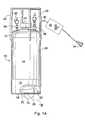
- FIG. 1Ais a schematic plan view of a container outfitted in accordance with one embodiment of the present invention with a partial section showing a bottom surface and sump.
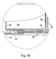
- FIG. 1Bis the partial section of FIG. 1 showing a sump and an external ultrasonic level sense positioned a spaced distance from a diptube.
- the present inventionis directed to a container for high purity chemical, such as is required in fabrication of semiconductor devices, flat panel displays and electronic devices. Such fabrication typically requires high purity raw materials or chemical precursors. High purity in this context typically is above 99.9 wt. %, frequently at least 99.999 wt. % and most recently at least 99.9999 wt. % pure. To maintain such purity in containers of high purity chemicals, such as liquid chemicals of the class of tetraethylorthosilicate (TEOS), containers must be designed for exacting purity and inertness.
- TEOStetraethylorthosilicate
- the diptubecan be used to dispense an inert carrier gas into the liquid chemical to bubble and entrain the chemical into the gas for removal through an outlet above the level of the liquid chemical, resulting in gas phase delivery from the container.
- inert carrier gassuch containers are known in the industry as bubblers.
- the diptubehas been a source of particle contamination in the past, because it is difficult to clean during the processing of containers to be filled with chemical.
- the diptubecan be designed to be removable from the container by utilizing a combination of an elastomer seal and a metal seal and/or a metal seal only.
- the diptubewill be sealed into the container via an elastomer O-ring or a metal seal, allowing chemical transfer through the tube and out of the container.
- the dip tubewill be sealed against environmental contamination via an all metal seal.
- the diptubecan then be cleaned much more thoroughly. Not only does this allow for more thorough cleaning during container processing, it also allows secondary devices to be added to the diptube, such as a removable filter. It will also allow for alternate materials to be used for the diptube. This has application in a non-corrosive, all metal, coated container.
- a non-intrusive level sensor that is attached to a non-wetted, permanent part of the containeris also contemplated by the present invention.
- a non-wetted, permanent part of the containerrefers to the level sensor being attached to a fixed, external surface or location on the container. The sensor would be attached one of two ways, permanently or so it is completely removable.
- completely removablethe present invention contemplates a level sensor that can be removed from the container without compromising the integrity of the chemical or the container. Attaching the level sensor to a non-wetted external surface part of the container increases the integrity of the chemical. Making the level sensor removable from the container allows for easy replacement in the field if the level sensor does fail.
- this present inventioncontemplates a removable chemical delivery piping or pressurizing gas inlet for bubbler or vapor delivery (“diptube”), and this may be installed in a number of equivalent fashions: a) from above the liquid level of the high purity chemical on the top surface of the container; b) from above the liquid level of the high purity chemical on the side surface of the container; c) from below the liquid level of the high purity chemical on the side surface of the container; d) from below the liquid level of the high purity chemical on the bottom surface of the container.
- Such top, side and bottom surfaces of the containerconstitute the external shell of the container.
- the interface or intersecting seams of the various surfacesmay be non-distinct, such as where the container has a generally spherical shape or the top and bottom surface represent a smooth curve continuation of the side surface or sidewall.
- the top surfaceis generally considered to be the area of the external surface which is at the highest point of the external surface of the container when it is in its normal service position.
- the bottom surfaceis the lowest most point of the external surface of the container when the container is in its normal service position. This excludes container skirts and chime rings.
- the external surfaces of the containerare the outside non-wetted surfaces of the external shell. All such variations and combinations are appropriate to meet the objectives of the present invention for high purity service, ease of cleaning and refurbishing and when liquid delivery is contemplated, removal of substantially all of the content of a high purity chemical container.
- the containers contemplated by the present inventioninclude containers that directly feed the furnace or tool of an electronic device fabrication furnace or tool where the chemical is actually used, sometimes referred to as an ampoule, canister or process container; and also to containers which refill such earlier described container, sometimes referred to as bulk containers.
- the containerscan be of any practical size, including from one or more liters to five or more liters. The size of the container is not critical.
- piping or valved manifoldswhich deliver chemical to or from the containers are well known in the industry and are not described further, but they are typically referred to as chemical delivery systems and include, in addition to piping and valved manifolds, sources of pressurized inert gas (carrier or push gas), an automated control unit, source of pneumatic air to operate pneumatic valves, vent lines, purge lines, sources of vacuum, flow control and monitoring hardware and other attendent devices, which are not the topic of the present invention.
- sources of pressurized inert gascarrier or push gas
- an automated control unitsource of pneumatic air to operate pneumatic valves
- vent linespurge lines
- sources of vacuumsources of vacuum
- flow control and monitoring hardware and other attendent deviceswhich are not the topic of the present invention.
- Chemicals that can be contained in the containers of the present inventionmay include: tetraethylorthosilicate (TEOS), borazine, aluminum trisec-butoxide, carbon tetrachloride, trichloroethanes, chloroform, trimethylphosphite, dichloroethylenes, trimethylborate, dichloromethane, titanium n-butoxide, dialkylsilane, diethylsilane, dibutylsilane, alkylsilanehydrides, hexafluoroacetylacetonatocopper(1)trimethylvinylsilane, isopropoxide, triethylphoshate, silicon tetrachloride, tantalum ethoxide, tetrakis(diethylamido)titanium, tetrakis(dimethylamido)titanium, bis-tertiarybutylamido silane, triethylborate, titanium
- an external ultrasonic level senseto sense liquid chemical level to avoid contamination of the chemical by the sensor and to facilitate sensor changeout without effecting the quality of the chemical.
- a significant aspect of the present inventionis the combination of an external ultrasonic level sensor positioned to detect liquid level in a container ultimately detecting residual chemical in a sump in the container which allows for accurate signals of chemical level in very small residual chemical volumes in the sump.
- the present inventionprovides a container with a sump adequate to accommodate the sensing function of the external ultrasonic level sensor and the lower end of a diptube for withdrawing chemical from the container.
- the sumpmust be sized adequately to not have the diptube interfere with the signals that the ultrasonic level sensor is generating and sensing in the liquid chemical in the sump.
- the external ultrasonic level sensoroperates by generating ultrasonic waves up through the bottom wall of the container, into the liquid and reflecting a portion of the waves off the surface of the liquid chemical.
- the reflected ultrasonic wavesare detected by the sensor and the time it takes the detection of the generated ultrasonic waves is proportional to the level of the liquid.
- Providing a sumpexcentuates the valid signal sensing by providing a larger column of liquid and thus a greater delta time interval to sense liquid level, yet on a smaller volume of liquid than a container that does not have a sump or a container that does not use its sump for the ultrasonic level sensing function, such as U.S. Pat. No. 6,077,356, which specifically teaches away from such a combination.
- the present inventionprovides the most accurate environment for level sensing to very small quantities of residual expensive chemical while allowing that residual chemical to be consumed by removal through the diptube terminating in the sump.
- sumpis cross-sectionally one half of the circle defined by the side wall of the container. Its bottom surface is approximately an inch below the bottom wall of the container, which bottom wall in this embodiment constitutes a generally smooth concave curving horizontal surface.
- Other sump geometriesare contemplated including horizontally circular cavities in the bottom wall, lower points in the bottom wall of the container, horizontally oval cavities, and horizontally dogbone shaped cavities. It is possible to use a bottom wall which is generally convex upward so that a continuous annular sump exists at the intersection of the bottom wall with the side wall of the container.
- the diptube and the ultrasonic sensorcould be placed diametrically opposite one another so as to have the greatest avoidance of any potential interference with the sensing of the sensor of the chemical level and the presence of the diptube, which could give a false reading of the chemical level.
- the size of the detection zone of the sump and the withdrawal zone of the sumpis dependent on the generation and detection parameters of the external ultrasonic level sensor.
- the detection zonemust be sufficiently large so that the reflected ultrasonic waves from the diptube do not cause significant interference with the reflected ultrasonic waves from the surface of the liquid in the container and especially the surface of the liquid residually left in the sump after chemical is emptied from the container above the sump. This will be effected by the placement of the diptube in the sump and its proximity to the detection zone and the bottom wall of the sump. This in turn is effected by the space at the top of the container to which the diptube is attached and the attachment configuration.
- the diptubeis connected to the outlet by one of: a metal to metal seal using a VCR® gland; an elastomeric seal between an outer wall of the dip tube and an inner diameter of the outlet of the container; and, a metal to metal seal of the outlet and a flange on the diptube or other known connection devices for connecting a pipe to an outlet in the process chemistry industry.
- the 0 -ring sealsare used with the diptube to allow chemical to flow from the container, through the diptube, out of the outlet and outlet valve when a pressure is applied to the container head space through the inlet and inlet valve using an inert pressurizing gas, such as nitrogen or helium.
- the metal gasketseals out any contamination from the environment.
- Removable diptube attachmentenhances the ability to clean or replace the diptube for high purity chemical service in the electronic fabrication industry.
- a removable diptubefacilitates the use of additional high purity options, such as the placement of filters, getters, membranes, dosing dispensers and similar devices which may need service or replacement over the life of the container.
- all componentsare manufactured from suitable metallic and non-metallic, compatible materials.
- suitable metallic and non-metallic, compatible materialscan include, but is not limited to, stainless steel (electropolished 316L), nickel, chromium, copper, glass, quartz, Teflon®, hastelloy, Vespel®, alumina, Kel-F, PEEK, Kynar®, silicon carbide or any other metallic, plastic or ceramic material, and variations and combinations are contemplated.
- a container 10with a side surface or wall 14 , a bottom or bottom surface 16 (in partial section) inside skirt 18 and attached to the lower or lowest most circumferential edge of side surface 14 , a top or top surface 12 , a chime ring assembly 46 for manually handling the container and protecting the valve and inlet/outlet orifices, an inlet pneumatic valve 40 connected to an inlet orifice 36 (valved inlet) typically connected to a source of inert pressurized gas (i.e., nitrogen, helium) to pressurize the headspace above the liquid level of the high purity liquid chemical to drive chemical out the diptube, an outlet orifice 38 with a removable diptube 22 (in this instance Teflon or similar inert plastic).
- inert pressurized gasi.e., nitrogen, helium
- the Teflon diptubeis removable from the container and disposable so that a new diptube can be used during refurbishing of the same material or a different material.
- the diptube 22has one end near outlet 38 and an other end which ends very near the bottom of the container sump 20 , shown in greater detail in FIG. 1B, so as, to remove most of the liquid high purity chemical during pressurization of the liquid's headspace.
- the present invention's level sensor 24can view the high purity chemical in the container 10 through the bottom surface of sump 20 .
- the bottom surface 16 of the external surface of the container 10has a generally concave downward curvature from said side surface 14 , and the sensor 24 is located at the lowest most point of the bottom surface 16 , which is the detection zone 48 of the sump 20 , so as to read the liquid level to the lowest fill of liquid chemical in the container.
- This placementoffers unique advantages because the sensor 24 is protected by the skirt 18 below the bottom surface 16 , which skirt 18 is a continuation of side wall 14 below the bottom surface 16 .
- the skirt 18 and the bottom surface 16form a protected cavity in which the sensor 24 can safely reside, isolated from external disturbance and in a position to avoid mishandling during transport.
- sensor 24would not project below the plane representing the lowest most circumferential edge of the skirt 18 , so as to avoid contact with any surface the container 10 may be placed upon.
- This placementalso provides the best performance of the ultrasonic level sensor 24 to sense the level of the liquid chemical contained in the container 10 and its sump 20 , because the sound waves pass through the liquid to the interface of the liquid chemical and the gaseous headspace to reflect off the interface and be sensed upon reflection to the sensor 24 .
- Liquidis a better conductor of sound waves than gas, so this placement affords the most precision and accuracy for an ultrasonic level sensor 24 to sense liquid level from an external surface of a container 10 .
- the ultrasonic signalis transmitted through the container and bounced off the surface or interface of the liquid high purity chemical and the gaseous headspace above the liquid surface in the container 10 .
- the levelis based on the speed of sound in the gas and/or liquid chemical.
- the signalwould be adjustable for different blanket gases used.
- Appropriate ultrasonic level sensorsare available commercially, such as the ML101 from Cosense, Inc. located at 155 Ricefield Lane, Hauppage, N.Y. 11788.
- the sensor signalis transmitted through its connector wire 26 , up the side wall 14 of container 10 through a protective shroud 28 to cable 30 connecting to appropriate process electronics 32 for amplifying or modulating the signal, and final to a connector 34 for connection and transmission of the sensor signal to any process controller the container may be operating with.
- the containerhas a standard chime ring 46 which facilitates carrying as well as protecting outlet 38 , inlet 36 , pneumatic valves 40 and 42 and fill port 44 , all situated on top surface or wall 12 .
- the sump 20is shown in enlarged detail.
- the sumpcan be seen to include a detection zone 48 unoccupied by the diptube 22 and a withdrawal zone 50 where liquid chemical is withdrawn by nearby diptube 22 occupying that portion of the sump 20 , which is terminated very close to the bottom surface of the sump 20 by a distance 52 sufficient to use most of the residual chemical in the sump 20 without drawing any particulates into the diptube that would otherwise collect in the bottom of the sump.
- the distance 52could be 0.5 to 1.0 cm, but the actual distance is dependent on the need for utilization of the chemical contained in the container.
- the ultrasonic level sensoris a continuous sensing device, providing specific liquid chemical level detail at all levels, but it can also be discrete in nature, providing data only at levels predetermined by appropriate input of setpoints, programming or electrical monitoring. It is also completely outside the container. This non-intrusive level sensor will allow for higher chemical purity, because it removes one more source of contamination. Also, making the level sensor completely removable from the container will allow replacement of the level sensor in the field if the level sensor fails whether the container is inservice or not. Most significantly, providing a sump to allow nearly complete utilization of the liquid chemical product and to enhance the accuracy of the level sensor provides a significant advantage over the prior art.
- Sizing the sump to accommodate not only the diptube, but also the sensing function of the sensorprovides significant performance over the prior art. It is important to use the sump not only for liquid chemical withdrawal, but also to enhance signal accuracy for the sensor. To accomplish that, the sump must be sized to accommodate a detection zone reserved for the signals generated and received by the sensor, as well as a withdrawal zone for removing liquid chemical through the diptube.
Landscapes
- Physics & Mathematics (AREA)
- Acoustics & Sound (AREA)
- Electromagnetism (AREA)
- Thermal Sciences (AREA)
- Fluid Mechanics (AREA)
- General Physics & Mathematics (AREA)
- Measurement Of Levels Of Liquids Or Fluent Solid Materials (AREA)
- Containers And Packaging Bodies Having A Special Means To Remove Contents (AREA)
Abstract
Description
Claims (18)
Priority Applications (3)
| Application Number | Priority Date | Filing Date | Title |
|---|---|---|---|
| US09/876,243US6526824B2 (en) | 2001-06-07 | 2001-06-07 | High purity chemical container with external level sensor and liquid sump |
| TW91103366ATW538003B (en) | 2001-02-12 | 2002-02-25 | High purity chemical container with external level sensor and liquid sump |
| JP2002165522AJP2003075234A (en) | 2001-06-07 | 2002-06-06 | Vessel for high purity chemical material and its liquid surface measuring method |
Applications Claiming Priority (1)
| Application Number | Priority Date | Filing Date | Title |
|---|---|---|---|
| US09/876,243US6526824B2 (en) | 2001-06-07 | 2001-06-07 | High purity chemical container with external level sensor and liquid sump |
Publications (2)
| Publication Number | Publication Date |
|---|---|
| US20020184945A1 US20020184945A1 (en) | 2002-12-12 |
| US6526824B2true US6526824B2 (en) | 2003-03-04 |
Family
ID=25367260
Family Applications (1)
| Application Number | Title | Priority Date | Filing Date |
|---|---|---|---|
| US09/876,243Expired - LifetimeUS6526824B2 (en) | 2001-02-12 | 2001-06-07 | High purity chemical container with external level sensor and liquid sump |
Country Status (2)
| Country | Link |
|---|---|
| US (1) | US6526824B2 (en) |
| JP (1) | JP2003075234A (en) |
Cited By (22)
| Publication number | Priority date | Publication date | Assignee | Title |
|---|---|---|---|---|
| US20040262327A1 (en)* | 2003-06-24 | 2004-12-30 | Birtcher Charles Michael | High purity chemical container with diptube and level sensor terminating in lowest most point of concave floor |
| US20050022848A1 (en)* | 2000-06-08 | 2005-02-03 | Crisp Harry Lee | Dishwasher operable with supply distribution, dispensing and use system method |
| US6857541B1 (en)* | 2000-06-08 | 2005-02-22 | Beverage Works, Inc. | Drink supply canister for beverage dispensing apparatus |
| US6896159B2 (en) | 2000-06-08 | 2005-05-24 | Beverage Works, Inc. | Beverage dispensing apparatus having fluid director |
| US7004355B1 (en) | 2000-06-08 | 2006-02-28 | Beverage Works, Inc. | Beverage dispensing apparatus having drink supply canister holder |
| US7083071B1 (en) | 2000-06-08 | 2006-08-01 | Beverage Works, Inc. | Drink supply canister for beverage dispensing apparatus |
| US20090009179A1 (en)* | 2007-07-05 | 2009-01-08 | Baxter International Inc. | Apparatus and method for verifying a seal between mutiple chambers |
| US20090012453A1 (en)* | 2007-07-05 | 2009-01-08 | Baxter International Inc. | Mobile dialysis system having supply container detection |
| US20090014477A1 (en)* | 2007-04-12 | 2009-01-15 | Ronald Brenes | Pressure module for dispensing chemical solutions |
| US20090212178A1 (en)* | 2008-02-27 | 2009-08-27 | Baxter International Inc. | Dialysate bag seal breakage sensor incorporated in dialysate bag management |
| US20100256826A1 (en)* | 2000-06-08 | 2010-10-07 | Beverage Works, Inc. | Appliance having a user interface panel and a beverage dispenser |
| US20100326646A1 (en)* | 2008-06-27 | 2010-12-30 | Yong-Bum Kim | Method for controlling a hot water temperature using low flux in hot water supply system |
| US8257299B2 (en) | 2007-07-05 | 2012-09-04 | Baxter International | Dialysis methods and systems having autoconnection and autoidentification |
| EP2639331A2 (en) | 2012-03-16 | 2013-09-18 | Air Products And Chemicals, Inc. | Catalyst synthesis for organosilane sol-gel reactions |
| EP2840164A1 (en) | 2013-08-22 | 2015-02-25 | Air Products And Chemicals, Inc. | Compositions and methods using same for flowable oxide deposition |
| US20160376056A1 (en)* | 2014-03-13 | 2016-12-29 | Wuxi Huaying Microelectronics Technology Co., Ltd. | Chemical Container And Method For Manufacturing The Same |
| US9586003B2 (en) | 2007-07-05 | 2017-03-07 | Baxter International Inc. | Medical fluid machine with supply autoconnection |
| US9809711B2 (en) | 2012-01-17 | 2017-11-07 | Versum Materials Us, Llc | Catalyst and formulations comprising same for alkoxysilanes hydrolysis reaction in semiconductor process |
| US20190024816A1 (en)* | 2017-07-18 | 2019-01-24 | Versum Materials Us, Llc | Removable Valve Guard For Ampoules |
| US10293091B2 (en) | 2007-07-05 | 2019-05-21 | Baxter International Inc. | Dialysis system having an autoconnection mechanism |
| WO2019241763A1 (en) | 2018-06-15 | 2019-12-19 | Versum Materials Us, Llc | Siloxane compositions and methods for using the compositions to deposit silicon containing films |
| EP3686533A1 (en) | 2019-01-24 | 2020-07-29 | Versum Materials US, LLC | System and method for drying and analytical testing of containers |
Families Citing this family (17)
| Publication number | Priority date | Publication date | Assignee | Title |
|---|---|---|---|---|
| DE102004053474B4 (en)* | 2003-11-21 | 2014-02-06 | Merck Patent Gmbh | Method and system for filling, transporting, storing and removing liquid crystals |
| WO2006009841A2 (en)* | 2004-06-17 | 2006-01-26 | Vincent Joseph Pietrorazio | A device for monitoring a beverage consumption level |
| KR100780864B1 (en)* | 2006-05-25 | 2007-11-29 | 삼성전자주식회사 | Chemical supply apparatus, semiconductor manufacturing equipment and chemical supply method having same |
| US8524321B2 (en)* | 2007-01-29 | 2013-09-03 | Praxair Technology, Inc. | Reagent dispensing apparatus and delivery method |
| CN104816877B (en) | 2009-07-09 | 2018-02-02 | 恩特格里斯公司 | Liner-based storage system and method of transporting materials |
| DE102010035008A1 (en)* | 2010-08-20 | 2012-02-23 | Emitec Gesellschaft Für Emissionstechnologie Mbh | Urea container with ultrasonic sensor |
| JP2013540080A (en)* | 2010-10-11 | 2013-10-31 | アドバンスド テクノロジー マテリアルズ,インコーポレイテッド | Substantially rigid collapsible liner, liner for container and / or glass bottle replacement and reinforced rigid liner |
| EP2643094A4 (en) | 2010-11-23 | 2017-05-24 | Advanced Technology Materials, Inc. | Liner-based dispenser |
| US9211993B2 (en) | 2011-03-01 | 2015-12-15 | Advanced Technology Materials, Inc. | Nested blow molded liner and overpack and methods of making same |
| DE102011111555A1 (en)* | 2011-08-26 | 2013-02-28 | Man Truck & Bus Ag | Operating procedure for a vehicle |
| US9978585B2 (en) | 2012-06-01 | 2018-05-22 | Versum Materials Us, Llc | Organoaminodisilane precursors and methods for depositing films comprising same |
| US9337018B2 (en) | 2012-06-01 | 2016-05-10 | Air Products And Chemicals, Inc. | Methods for depositing films with organoaminodisilane precursors |
| CA2879609C (en)* | 2014-01-29 | 2020-04-28 | Robert D. Thibodeau | Refillable material transfer system |
| CN104129750B (en)* | 2014-07-10 | 2016-05-18 | 江阴江化微电子材料股份有限公司 | Liquid electronic chemicals dosing filling machine |
| EP3385635B1 (en)* | 2016-03-03 | 2020-05-06 | Mitsubishi Electric Corporation | Air conditioner |
| US10323975B2 (en)* | 2016-12-29 | 2019-06-18 | Kegsafe Llc | Non-intrusive ultrasonic measuring of fluids in a beverage keg |
| CN107284673A (en)* | 2017-07-28 | 2017-10-24 | 四川雷神空天科技有限公司 | Liquid containing device |
Citations (16)
| Publication number | Priority date | Publication date | Assignee | Title |
|---|---|---|---|---|
| US3100885A (en)* | 1961-08-14 | 1963-08-13 | Gulton Ind Inc | Ultrasonic liquid level gauge |
| US4053085A (en) | 1975-10-10 | 1977-10-11 | Block Engineering, Inc. | Dissimilar materials seal for high pressure, high temperature and chemically reactive environments |
| US4440319A (en) | 1981-07-21 | 1984-04-03 | Nitchman Harold L | System, apparatus, and method of dispensing a liquid from a semi-bulk disposable container |
| US4580448A (en)* | 1982-09-15 | 1986-04-08 | Acumet Precision Instruments, Ltd. | Method and apparatus for ultrasonic measurement of a physical parameter |
| US4770038A (en)* | 1986-02-13 | 1988-09-13 | The United States Of America As Represented By The Administrator Of National Aeronautics And Space Administration | Ultrasonic depth gauge for liquids under high pressure |
| US4949878A (en)* | 1988-12-27 | 1990-08-21 | Monsanto Company | Reusable container system |
| GB2259508A (en)* | 1991-08-30 | 1993-03-17 | Dominic James Robinson | Valved liquid transfer systems |
| US5199603A (en) | 1991-11-26 | 1993-04-06 | Prescott Norman F | Delivery system for organometallic compounds |
| US5303585A (en)* | 1991-10-31 | 1994-04-19 | Jtl Medical Corporation | Fluid volume sensor |
| US5562132A (en) | 1993-04-28 | 1996-10-08 | Advanced Delivery & Chemical Systems, Inc. | Bulk containers for high purity chemical delivery systems |
| US5663503A (en) | 1995-09-08 | 1997-09-02 | Cosense, Inc. | Invasive and non-invasive ultrasonic sensor with continuous and demand self-test |
| US6077356A (en)* | 1996-12-17 | 2000-06-20 | Advanced Technology Materials, Inc. | Reagent supply vessel for chemical vapor deposition |
| US6202484B1 (en)* | 1996-01-03 | 2001-03-20 | Siemens Aktiengesellschaft | Method and device for determining a liquid level with the aid of ultrasonic pulses |
| US6264064B1 (en)* | 1999-10-14 | 2001-07-24 | Air Products And Chemicals, Inc. | Chemical delivery system with ultrasonic fluid sensors |
| US6397656B1 (en)* | 1999-01-25 | 2002-06-04 | Yamatake Corporation | System and method for detecting liquid serving as object to be detected in vessel using ultrasonic sensor |
| US20020108670A1 (en)* | 2001-02-12 | 2002-08-15 | Baker John Eric | High purity chemical container with external level sensor and removable dip tube |
- 2001
- 2001-06-07USUS09/876,243patent/US6526824B2/ennot_activeExpired - Lifetime
- 2002
- 2002-06-06JPJP2002165522Apatent/JP2003075234A/enactivePending
Patent Citations (16)
| Publication number | Priority date | Publication date | Assignee | Title |
|---|---|---|---|---|
| US3100885A (en)* | 1961-08-14 | 1963-08-13 | Gulton Ind Inc | Ultrasonic liquid level gauge |
| US4053085A (en) | 1975-10-10 | 1977-10-11 | Block Engineering, Inc. | Dissimilar materials seal for high pressure, high temperature and chemically reactive environments |
| US4440319A (en) | 1981-07-21 | 1984-04-03 | Nitchman Harold L | System, apparatus, and method of dispensing a liquid from a semi-bulk disposable container |
| US4580448A (en)* | 1982-09-15 | 1986-04-08 | Acumet Precision Instruments, Ltd. | Method and apparatus for ultrasonic measurement of a physical parameter |
| US4770038A (en)* | 1986-02-13 | 1988-09-13 | The United States Of America As Represented By The Administrator Of National Aeronautics And Space Administration | Ultrasonic depth gauge for liquids under high pressure |
| US4949878A (en)* | 1988-12-27 | 1990-08-21 | Monsanto Company | Reusable container system |
| GB2259508A (en)* | 1991-08-30 | 1993-03-17 | Dominic James Robinson | Valved liquid transfer systems |
| US5303585A (en)* | 1991-10-31 | 1994-04-19 | Jtl Medical Corporation | Fluid volume sensor |
| US5199603A (en) | 1991-11-26 | 1993-04-06 | Prescott Norman F | Delivery system for organometallic compounds |
| US5562132A (en) | 1993-04-28 | 1996-10-08 | Advanced Delivery & Chemical Systems, Inc. | Bulk containers for high purity chemical delivery systems |
| US5663503A (en) | 1995-09-08 | 1997-09-02 | Cosense, Inc. | Invasive and non-invasive ultrasonic sensor with continuous and demand self-test |
| US6202484B1 (en)* | 1996-01-03 | 2001-03-20 | Siemens Aktiengesellschaft | Method and device for determining a liquid level with the aid of ultrasonic pulses |
| US6077356A (en)* | 1996-12-17 | 2000-06-20 | Advanced Technology Materials, Inc. | Reagent supply vessel for chemical vapor deposition |
| US6397656B1 (en)* | 1999-01-25 | 2002-06-04 | Yamatake Corporation | System and method for detecting liquid serving as object to be detected in vessel using ultrasonic sensor |
| US6264064B1 (en)* | 1999-10-14 | 2001-07-24 | Air Products And Chemicals, Inc. | Chemical delivery system with ultrasonic fluid sensors |
| US20020108670A1 (en)* | 2001-02-12 | 2002-08-15 | Baker John Eric | High purity chemical container with external level sensor and removable dip tube |
Cited By (69)
| Publication number | Priority date | Publication date | Assignee | Title |
|---|---|---|---|---|
| US7689476B2 (en) | 2000-06-08 | 2010-03-30 | Beverage Works, Inc. | Washing machine operable with supply distribution, dispensing and use system method |
| US8606395B2 (en) | 2000-06-08 | 2013-12-10 | Beverage Works, Inc. | Appliance having a user interface panel and a beverage dispenser |
| US6857541B1 (en)* | 2000-06-08 | 2005-02-22 | Beverage Works, Inc. | Drink supply canister for beverage dispensing apparatus |
| US6896159B2 (en) | 2000-06-08 | 2005-05-24 | Beverage Works, Inc. | Beverage dispensing apparatus having fluid director |
| US20050121467A1 (en)* | 2000-06-08 | 2005-06-09 | Crisp Harry L.Iii | Refrigerator having a fluid director access door |
| US20050133532A1 (en)* | 2000-06-08 | 2005-06-23 | Crisp Harry L.Iii | Beverage dispensing apparatus having a valve actuator control system |
| US6915925B2 (en) | 2000-06-08 | 2005-07-12 | Beverage Works, Inc. | Refrigerator having a gas supply apparatus for pressurizing drink supply canisters |
| US20050167446A1 (en)* | 2000-06-08 | 2005-08-04 | Crisp Harry L.Iii | Refrigerator having a gas line which pressurizes a drink supply container for producing beverages |
| US20050177454A1 (en)* | 2000-06-08 | 2005-08-11 | Crisp Harry L.Iii | Drink supply canister having a drink supply outlet valve with a rotatable member |
| US6986263B2 (en) | 2000-06-08 | 2006-01-17 | Beverage Works, Inc. | Refrigerator having a beverage dispenser and a display device |
| US7004355B1 (en) | 2000-06-08 | 2006-02-28 | Beverage Works, Inc. | Beverage dispensing apparatus having drink supply canister holder |
| US7032779B2 (en) | 2000-06-08 | 2006-04-25 | Beverage Works, Inc. | Refrigerator having a beverage dispensing apparatus with a drink supply canister holder |
| US7032780B2 (en) | 2000-06-08 | 2006-04-25 | Beverage Works, Inc. | Refrigerator that displays beverage images, reads beverage data files and produces beverages |
| US20060151529A1 (en)* | 2000-06-08 | 2006-07-13 | Crisp Harry L Iii | Refrigerator operable to display an image and output a carbonated beverage |
| US20060157505A1 (en)* | 2000-06-08 | 2006-07-20 | Crisp Harry L Iii | Refrigerator which removably holds a drink supply container having a valve co-acting with an engager |
| US7083071B1 (en) | 2000-06-08 | 2006-08-01 | Beverage Works, Inc. | Drink supply canister for beverage dispensing apparatus |
| US20060196887A1 (en)* | 2000-06-08 | 2006-09-07 | Beverage Works, Inc. | Refrigerator having a valve engagement mechanism operable to engage multiple valves of one end of a liquid container |
| US20060219739A1 (en)* | 2000-06-08 | 2006-10-05 | Beverage Works, Inc. | Drink supply container having an end member supporting gas inlet and outlet valves which extend perpendicular to the end member |
| US9090447B2 (en) | 2000-06-08 | 2015-07-28 | Beverage Works, Inc. | Appliance having a user interface panel and a beverage dispenser |
| US7168592B2 (en) | 2000-06-08 | 2007-01-30 | Beverage Works, Inc. | Refrigerator having a gas line which pressurizes a drink supply container for producing beverages |
| US7203572B2 (en) | 2000-06-08 | 2007-04-10 | Beverage Works, Inc. | System and method for distributing drink supply containers |
| US7204259B2 (en) | 2000-06-08 | 2007-04-17 | Beverage Works, Inc. | Dishwasher operable with supply distribution, dispensing and use system method |
| US7278552B2 (en) | 2000-06-08 | 2007-10-09 | Beverage Works, Inc. | Water supplier for a beverage dispensing apparatus of a refrigerator |
| US7337924B2 (en) | 2000-06-08 | 2008-03-04 | Beverage Works, Inc. | Refrigerator which removably holds a drink supply container having a valve co-acting with an engager |
| US7356381B2 (en) | 2000-06-08 | 2008-04-08 | Beverage Works, Inc. | Refrigerator operable to display an image and output a carbonated beverage |
| US7367480B2 (en) | 2000-06-08 | 2008-05-06 | Beverage Works, Inc. | Drink supply canister having a self-closing pressurization valve operable to receive a pressurization pin |
| US7389895B2 (en) | 2000-06-08 | 2008-06-24 | Beverage Works, Inc. | Drink supply canister having a drink supply outlet valve with a rotatable member |
| US7416097B2 (en) | 2000-06-08 | 2008-08-26 | Beverage Works, Inc. | Drink supply container valve assembly |
| US7419073B2 (en) | 2000-06-08 | 2008-09-02 | Beverage Works, In.C | Refrigerator having a fluid director access door |
| US9090448B2 (en) | 2000-06-08 | 2015-07-28 | Beverage Works, Inc. | Appliance having a user interface panel and a beverage dispenser |
| US9090449B2 (en) | 2000-06-08 | 2015-07-28 | Beverage Works, Inc. | Appliance having a user interface panel and a beverage dispenser |
| US9090446B2 (en) | 2000-06-08 | 2015-07-28 | Beverage Works, Inc. | Appliance with dispenser |
| US7484388B2 (en) | 2000-06-08 | 2009-02-03 | Beverage Works, Inc. | Appliance operable with supply distribution, dispensing and use system and method |
| US7708172B2 (en) | 2000-06-08 | 2010-05-04 | Igt | Drink supply container having an end member supporting gas inlet and outlet valves which extend perpendicular to the end member |
| US20050022848A1 (en)* | 2000-06-08 | 2005-02-03 | Crisp Harry Lee | Dishwasher operable with supply distribution, dispensing and use system method |
| US7611031B2 (en) | 2000-06-08 | 2009-11-03 | Beverage Works, Inc. | Beverage dispensing apparatus having a valve actuator control system |
| US8565917B2 (en) | 2000-06-08 | 2013-10-22 | Beverage Works, Inc. | Appliance with dispenser |
| US8548624B2 (en) | 2000-06-08 | 2013-10-01 | Beverage Works, Inc. | Appliance having a user interface panel and a beverage dispenser |
| US20100256826A1 (en)* | 2000-06-08 | 2010-10-07 | Beverage Works, Inc. | Appliance having a user interface panel and a beverage dispenser |
| US20100307185A1 (en)* | 2000-06-08 | 2010-12-09 | Beverage Works, Inc. | Appliance with dispenser |
| US8290615B2 (en) | 2000-06-08 | 2012-10-16 | Beverage Works, Inc. | Appliance with dispenser |
| US7918368B2 (en) | 2000-06-08 | 2011-04-05 | Beverage Works, Inc. | Refrigerator having a valve engagement mechanism operable to engage multiple valves of one end of a liquid container |
| US8103378B2 (en) | 2000-06-08 | 2012-01-24 | Beverage Works, Inc. | Appliance having a user interface panel and a beverage dispenser |
| US8290616B2 (en) | 2000-06-08 | 2012-10-16 | Beverage Works, Inc. | Appliance having a user interface panel and a beverage dispenser |
| US8190290B2 (en) | 2000-06-08 | 2012-05-29 | Beverage Works, Inc. | Appliance with dispenser |
| US20040262327A1 (en)* | 2003-06-24 | 2004-12-30 | Birtcher Charles Michael | High purity chemical container with diptube and level sensor terminating in lowest most point of concave floor |
| US7124913B2 (en)* | 2003-06-24 | 2006-10-24 | Air Products And Chemicals, Inc. | High purity chemical container with diptube and level sensor terminating in lowest most point of concave floor |
| US20090014477A1 (en)* | 2007-04-12 | 2009-01-15 | Ronald Brenes | Pressure module for dispensing chemical solutions |
| US11730868B2 (en) | 2007-07-05 | 2023-08-22 | Baxter International Inc. | Dialysis system having an autoconnection mechanism |
| US8257299B2 (en) | 2007-07-05 | 2012-09-04 | Baxter International | Dialysis methods and systems having autoconnection and autoidentification |
| US8105266B2 (en) | 2007-07-05 | 2012-01-31 | Baxter International Inc. | Mobile dialysis system having supply container detection |
| US9586003B2 (en) | 2007-07-05 | 2017-03-07 | Baxter International Inc. | Medical fluid machine with supply autoconnection |
| US10293091B2 (en) | 2007-07-05 | 2019-05-21 | Baxter International Inc. | Dialysis system having an autoconnection mechanism |
| US7808246B2 (en) | 2007-07-05 | 2010-10-05 | Baxter International Inc. | Apparatus and method for verifying a seal between multiple chambers |
| US20090009179A1 (en)* | 2007-07-05 | 2009-01-08 | Baxter International Inc. | Apparatus and method for verifying a seal between mutiple chambers |
| US20090012453A1 (en)* | 2007-07-05 | 2009-01-08 | Baxter International Inc. | Mobile dialysis system having supply container detection |
| US20090212178A1 (en)* | 2008-02-27 | 2009-08-27 | Baxter International Inc. | Dialysate bag seal breakage sensor incorporated in dialysate bag management |
| US8152116B2 (en) | 2008-02-27 | 2012-04-10 | Baxter International Inc. | Dialysate bag seal breakage sensor incorporated in dialysate bag management |
| US20100326646A1 (en)* | 2008-06-27 | 2010-12-30 | Yong-Bum Kim | Method for controlling a hot water temperature using low flux in hot water supply system |
| US9809711B2 (en) | 2012-01-17 | 2017-11-07 | Versum Materials Us, Llc | Catalyst and formulations comprising same for alkoxysilanes hydrolysis reaction in semiconductor process |
| EP2639331A2 (en) | 2012-03-16 | 2013-09-18 | Air Products And Chemicals, Inc. | Catalyst synthesis for organosilane sol-gel reactions |
| US10170297B2 (en) | 2013-08-22 | 2019-01-01 | Versum Materials Us, Llc | Compositions and methods using same for flowable oxide deposition |
| EP2840164A1 (en) | 2013-08-22 | 2015-02-25 | Air Products And Chemicals, Inc. | Compositions and methods using same for flowable oxide deposition |
| US10196172B2 (en)* | 2014-03-13 | 2019-02-05 | Wuxi Huaying Microelectronics Technology Co., Ltd. | Chemical container and method for manufacturing the same |
| US20160376056A1 (en)* | 2014-03-13 | 2016-12-29 | Wuxi Huaying Microelectronics Technology Co., Ltd. | Chemical Container And Method For Manufacturing The Same |
| US20190024816A1 (en)* | 2017-07-18 | 2019-01-24 | Versum Materials Us, Llc | Removable Valve Guard For Ampoules |
| US10871238B2 (en)* | 2017-07-18 | 2020-12-22 | Versum Materials Us, Llc | Removable valve guard for ampoules |
| WO2019241763A1 (en) | 2018-06-15 | 2019-12-19 | Versum Materials Us, Llc | Siloxane compositions and methods for using the compositions to deposit silicon containing films |
| EP3686533A1 (en) | 2019-01-24 | 2020-07-29 | Versum Materials US, LLC | System and method for drying and analytical testing of containers |
Also Published As
| Publication number | Publication date |
|---|---|
| US20020184945A1 (en) | 2002-12-12 |
| JP2003075234A (en) | 2003-03-12 |
Similar Documents
| Publication | Publication Date | Title |
|---|---|---|
| US6526824B2 (en) | High purity chemical container with external level sensor and liquid sump | |
| US20020108670A1 (en) | High purity chemical container with external level sensor and removable dip tube | |
| US7124913B2 (en) | High purity chemical container with diptube and level sensor terminating in lowest most point of concave floor | |
| JP3527470B2 (en) | Chemical distribution system and method for detecting when a reservoir containing a liquid is empty | |
| EP3473747B1 (en) | Chemical precursor delivery method in a deposition process | |
| US6840252B2 (en) | Multiple contents container assembly for ultrapure solvent purging | |
| US20030131885A1 (en) | Cabinet for chemical delivery with solvent purging | |
| CN103101867A (en) | Liquid dispensing systems encompassing gas removal | |
| EP1006219B1 (en) | Ultrasonic level sensing in a chemical refill system | |
| US6581649B2 (en) | Methods and apparatus for delivering high purity liquids with low vapor pressure | |
| US20200131630A1 (en) | Aerosol-free vessel for bubbling chemical precursors in a deposition process | |
| WO2002088692A2 (en) | Apparatus for detecting the presence of liquid in a storage container and corresponding method | |
| US20030185690A1 (en) | Systems and methods for transferring and delivering a liquid chemical from a source to an end use station | |
| US6805848B2 (en) | Built-in purifier for horizontal liquefied gas cylinders | |
| TW538003B (en) | High purity chemical container with external level sensor and liquid sump |
Legal Events
| Date | Code | Title | Description |
|---|---|---|---|
| AS | Assignment | Owner name:AIR PRODUCTS AND CHEMICALS, INC., PENNSYLVANIA Free format text:ASSIGNMENT OF ASSIGNORS INTEREST;ASSIGNORS:CHASE, GEOFFREY L.;BAKER, JOHN ERIC;SENECAL, LEE;AND OTHERS;REEL/FRAME:011895/0403;SIGNING DATES FROM 20010530 TO 20010607 | |
| STCF | Information on status: patent grant | Free format text:PATENTED CASE | |
| FPAY | Fee payment | Year of fee payment:4 | |
| FEPP | Fee payment procedure | Free format text:PAYOR NUMBER ASSIGNED (ORIGINAL EVENT CODE: ASPN); ENTITY STATUS OF PATENT OWNER: LARGE ENTITY | |
| FPAY | Fee payment | Year of fee payment:8 | |
| FPAY | Fee payment | Year of fee payment:12 | |
| AS | Assignment | Owner name:CITIBANK, N.A., AS COLLATERAL AGENT, DELAWARE Free format text:PATENT SECURITY AGREEMENT;ASSIGNOR:VERSUM MATERIALS US, LLC;REEL/FRAME:040503/0442 Effective date:20160930 | |
| AS | Assignment | Owner name:VERSUM MATERIALS US, LLC, ARIZONA Free format text:ASSIGNMENT OF ASSIGNORS INTEREST;ASSIGNOR:AIR PRODUCTS AND CHEMICALS, INC.;REEL/FRAME:041772/0733 Effective date:20170214 | |
| AS | Assignment | Owner name:VERSUM MATERIALS US, LLC, ARIZONA Free format text:RELEASE BY SECURED PARTY;ASSIGNOR:CITIBANK, N.A., AS AGENT;REEL/FRAME:050647/0001 Effective date:20191007 |