US6526677B1 - Snowplow mounting assembly - Google Patents
Snowplow mounting assemblyDownload PDFInfo
- Publication number
- US6526677B1 US6526677B1US09/684,269US68426900AUS6526677B1US 6526677 B1US6526677 B1US 6526677B1US 68426900 AUS68426900 AUS 68426900AUS 6526677 B1US6526677 B1US 6526677B1
- Authority
- US
- United States
- Prior art keywords
- mount frame
- frame
- snowplow assembly
- assembly
- latch
- Prior art date
- Legal status (The legal status is an assumption and is not a legal conclusion. Google has not performed a legal analysis and makes no representation as to the accuracy of the status listed.)
- Expired - Lifetime
Links
- 230000000712assemblyEffects0.000claimsabstractdescription104
- 238000000429assemblyMethods0.000claimsabstractdescription104
- 230000007246mechanismEffects0.000claimsabstractdescription13
- 230000033001locomotionEffects0.000claimsdescription12
- 238000000926separation methodMethods0.000claims1
- 230000009471actionEffects0.000description6
- 230000006835compressionEffects0.000description4
- 238000007906compressionMethods0.000description4
- 230000008901benefitEffects0.000description3
- 238000010276constructionMethods0.000description1
- 230000001419dependent effectEffects0.000description1
- 238000009434installationMethods0.000description1
- 238000012986modificationMethods0.000description1
- 230000004048modificationEffects0.000description1
- 230000002250progressing effectEffects0.000description1
- 230000004044responseEffects0.000description1
- 230000000717retained effectEffects0.000description1
Images


Classifications
- E—FIXED CONSTRUCTIONS
- E01—CONSTRUCTION OF ROADS, RAILWAYS, OR BRIDGES
- E01H—STREET CLEANING; CLEANING OF PERMANENT WAYS; CLEANING BEACHES; DISPERSING OR PREVENTING FOG IN GENERAL CLEANING STREET OR RAILWAY FURNITURE OR TUNNEL WALLS
- E01H5/00—Removing snow or ice from roads or like surfaces; Grading or roughening snow or ice
- E01H5/04—Apparatus propelled by animal or engine power; Apparatus propelled by hand with driven dislodging or conveying levelling elements, conveying pneumatically for the dislodged material
- E01H5/06—Apparatus propelled by animal or engine power; Apparatus propelled by hand with driven dislodging or conveying levelling elements, conveying pneumatically for the dislodged material dislodging essentially by non-driven elements, e.g. scraper blades, snow-plough blades, scoop blades
- E01H5/065—Apparatus propelled by animal or engine power; Apparatus propelled by hand with driven dislodging or conveying levelling elements, conveying pneumatically for the dislodged material dislodging essentially by non-driven elements, e.g. scraper blades, snow-plough blades, scoop blades characterised by the form of the snow-plough blade, e.g. flexible, or by snow-plough blade accessories
- E01H5/066—Snow-plough blade accessories, e.g. deflector plates, skid shoes
Definitions
- This inventionrelates to snow removal equipment and, more particularly, to a snowplow mounting assembly for removably securing a snowplow to a vehicle.
- many different types of snowplowing arrangementshave been invented. Numerous of these snowplows have been configured to remove snow efficiently from a hill or other uneven surface.
- many of these snowplowshave been built with hydraulics in order to lift the snowplow into and out of engagement with the road surface.
- U.S. Pat. No. 3,605,906discloses a snowplow which is capable of rotating about a longitudinally extending axis as well as a transversely extending axis perpendicular to the direction of travel of the vehicle. By fixing the position of the snowplow along these two axes, the snowplow may be moved to a desired position.
- U.S. Pat. Nos. 3,822,751 and 4,821,436also disclose snowplow s which may be mounted to the front of a vehicle and rotated about at least two axes so as to adjust the snowplow blade to a desired position.
- a snowplow assemblyAnother desirable feature of a snowplow assembly is a jack stand or lift stand capable of supporting the snowplow assembly when not in use.
- Several patentsdisclose snowplow assemblies which have lift stands. Applicants' own U.S. Pat. No. 5,125,174, reissued as U.S. Pat. No. 35,700, discloses a snowplow assembly having a lift stand which is pivotable about a horizontal axis and may be lifted out of the way when the snowplow assembly is being used to plow snow.
- the invention of this applicationprovides a number of features and advantages over and above the noted prior art and comprises a snowplow mounting assembly comprising two principal elements: a mount frame adapted to be attached to a vehicle and a snowplow assembly removably attachable to the mount frame.
- the mount frame of the snowplow mounting assemblycomprises a first portion adapted to be attached to a vehicle and a second portion detachable from the first portion.
- the second portioncomprises a pair of spaced receivers, each having a generally rectangular cross-sectional configuration.
- Each receiverhas a top plate, a bottom plate and a pair of laterally spaced side plates.
- the bottom platehas a depending lip, and at least one of the side plates has a flared portion.
- a pair of spaced latch pinsare located outside of the receivers of the mount frame.
- the snowplow assembly of the snowplow mounting assemblyis releasably securable to the mount frame located on the front of a vehicle.
- the snowplow assemblycomprises a lift frame, a trunnion and an A-frame.
- the lift frameis generally vertically oriented and includes a pair of headlights.
- the trunnionis transversely oriented and pivotable about a first transverse horizontal axis relative to the lift frame.
- the A-frameis pivotable about a horizontal longitudinally extending axis relative to the trunnion.
- a snowplow bladeis attached to the front end of the A-frame.
- the lift frameincludes a lifter or hydraulic cylinder, which is used to lift the snowplow blade vertically upward.
- a chain or other similar structureextends between the front of the A-frame and lift arms pivotably secured to the lift frame.
- a piston rodpushes the lift arms upwardly causing the chain to pull the blade upwardly.
- the lift framealso includes a pair of stand assemblies which are pivotable about a second transversely extending horizontal pivot axis. These stand assemblies are movable between a down position in which the stand assemblies support the snowplow assembly and an up position in which the stand assemblies do not support the snowplow assembly.
- a latch hookis located on an upper end of each of the stand assemblies. When the stand assemblies are pivoted from their down position toward their up position, the latch hooks move rearwardly and downwardly into engagement with the latch pins of the mount frame to secure the snowplow assembly to the mount frame at the front of a vehicle.
- a lock pin assembly on each of the stand assembliesis adapted to lock the stand assemblies in either the up position or the down position.
- the lift framefurther comprises a pair of horns extending rearwardly from the lift frame.
- the horns of the lift frameare received in the receivers of the mount frame when the snowplow assembly and mount frame are secured together.
- Each of the stand assembliesis separately and continuously adjustable in length.
- This adjustable length featureenables the snowplow assembly to be placed on an uneven surface, such as a hill, in such a position that it can easily be mounted on the front of a vehicle.
- the driver of the vehiclemay drive the receivers of the mount frame into engagement with the horns projecting rearwardly from the lift frame of the snowplow assembly.
- the driverthen manually rotates the stand assemblies about the second transversely extending pivot axis until the latch hooks of the stand assemblies engage the latch pins of the mount frame.
- the driver of the vehiclemay secure the snowplow assembly to the mount frame secured to the vehicle and proceed to move snow.
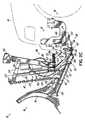
- FIG. 1is an exploded perspective view of the snowplow mounting assembly of the present invention including a mount frame and a snowplow assembly releasably securable to the mount frame.
- FIG. 2Ais a side elevational view of the snowplow mounting assembly of the present invention with the mount frame secured to a vehicle before the mount frame is engaged with the snowplow assembly.
- FIG. 2Bis a side elevational view of the mount frame and snowplow assembly of FIG. 2A secured with one another with the snowplow blade in a down position.
- FIG. 2Cis a view of the mount frame and snowplow assembly secured to one another like FIG. 2B but with the snowplow blade being raised to an up position.
- FIG. 3Ais a top view of the snowplow assembly of the present invention secured to the mount frame with the snowplow blade being perpendicular to the direction of travel of the vehicle.
- FIG. 3Bis a top view of the snowplow assembly of FIG. 3A illustrating the snowplow blade being angled to one side in order to push the snow to one side of the road as the vehicle travels down the road.
- FIG. 4is a perspective view of one of the stand assemblies of the present invention.
- FIG. 1there is illustrated a snowplow mounting assembly 10 and comprising a mount frame 12 adapted to be secured to a vehicle 14 and a snowplow assembly 16 .
- mount frame 12comprises a first portion 18 adapted to be attached or secured to the vehicle 14 and a second portion 20 quickly and readily detachable from the first portion 18 without the use of tools, i.e. not requiring wrenches, sockets, removing nuts from bolts, etc.
- Such a two piece designis advantageous in order that it provides improved, i.e. increased, ground clearance of the mount frame 12 on vehicle 14 , and/or increased “approach angle” of the vehicle 14 , when snowplow assembly 16 is removed from the vehicle 14 during nonuse, as second portion can also be removed leaving only first portion 18 mounted to the vehicle.
- approach anglerefers to the angle between the horizontal road surface and a straight line extending from the tangent point of the front tire contacting the road surface to the mount frame, at whatever mount frame location produces the smallest such angle. Stated otherwise, the approach angle is the angle formed between the road surface and a straight line originating at the tangent point of where the front tire contacts the road surface and swung upwardly to the point where that line first contacts any point on the mount frame.
- the second portion 20 of the mount frame 12comprises a pair of receivers 22 .
- Each of the receivers 22is detachably secured to a respective first portion 18 of the mount frame 12 with a fixed rear pin 24 and a removeable front pin 26 .
- a slot 30 in receiver 22engages fixed rear pin 24 which is welded to first portion 18 in rearward most hole 28 .
- a through passageway 31 in receiver 22is aligned with forward most hole 28 in first portion 18 and accepts removeable pin 26 .
- Removeable pin 26includes a tab 27 fixedly secured thereto with a hole 29 therein that engages over a latch pin 94 secured to receiver 22 , which will be described in more detail below.
- a “hairpin”(not shown) is manually installed in a hole (not shown) in latch pin 94 (without the use of tools) to secure tab 27 on latch pin 94 and consequently to secure pin 26 in passageway 31 .
- no tools, wrenches, sockets, etcare required to quickly and readily detach second portion 20 from first portion 18 .
- Each of the receivers 22has a generally rectangular cross-sectional configuration and has a bottom plate 34 , a top plate 35 and a pair of opposed, parallel, laterally spaced side plates 36 .
- the bottom plate 34 , top plate 35 and side plates 36define an interior 44 of each receiver 22 .
- Each laterally inboard side plate 36includes a notch or relief 36 a extending from a front edge of that side plate 36 rearwardly.
- a pair of horns 42extend rearwardly from a lift frame 46 of the snowplow assembly 16 .
- the horns 42are interconnected by a round tube 43 .
- the horns 42are received in the receivers 22 and the tube 43 is received in the notches 36 a .
- the laterally inboard side plates 36carry thrust loads from the snowplow assembly 16 transmitted to those side plates 36 by the tube 43
- the bottom 34 and top 35 platescarry moment loads from the snowplow assembly 16 transmitted to those plates 34 , 35 by the horns 42
- the outermost side plate 36 of each receiver 22has an outwardly flared portion 38
- the bottom plate 34has a depending lip 40 . This lip 40 and flared portion 38 aid in guiding each horn 42 into the interior 44 of its respective receiver 22 in a manner which will be described in more detail below.
- the snowplow assembly 16comprises three principal elements best illustrated in FIGS. 3 A and 3 B: a lift frame 46 , a trunnion 48 and an A-frame 50 .
- a lift frame 46a trunnion 48
- A-frame 50a trunnion 48
- the rearwardmost one of these elementsis the lift frame 46 best illustrated in FIG. 1 .
- the lift frame 46is generally vertically oriented and includes lower portion 47 and a pair of supports 56 extending upwardly from the lower portion 47 .
- a pair of headlights 52are located at the upper ends of the supports 56 .
- the lift frame 46further includes a pair of lift arms 54 extending forwardly from vertical supports 56 at the upper ends of the supports 56 .
- the lift arms 54are joined together with a lift bracket 55 .
- a hydraulically operated lifter 59comprising piston rod 60 and cylinder 62 extends between the front of the lift arms 54 and a bracket 58 secured to a lower portion of the lift frame 46 . This hydraulically operated lifter 59 functions to lift the A-frame 50 from a lowered position illustrated in FIG.
- the second component of the snowplow assembly 16is the trunnion 48 .
- the trunnion 48comprises a transversely extending bar which is pivotable about the prior-mentioned first transversely extending horizontal axis 64 relative to the lift frame 46 .
- both the A-frame 50 and trunnion 48pivot about the first transversely extending axis 64 .
- the trunnion 48is secured to the A-frame 50 with a bolt 66 or other fastener which defines a longitudinally extending axis 68 .
- the third and last element of the snowplow assemblyis the A-frame 50 best illustrated in FIGS. 3A and 3B.
- the A-frame 50comprises a back bar 70 and a pair of side bars 72 arranged in a triangular or “A” configuration.
- the back bar 70is secured to the trunnion 48 with the prior-mentioned fastener 66 .
- a snowplow blade 74is secured to the front of the A-frame 50 .
- the snowplow blade 74In order to adjust the snowplow blade 74 such that one is able to push the snow to one side of the road, the snowplow blade 74 is pivotable about a vertical axis 76 illustrated in FIGS. 3A and 3B.
- the snowplow blade 74is movable about this axis by the operation of a pair of hydraulic adjusters 77 .
- Each adjuster 78comprises a piston rod 80 extending forwardly from a cylinder 78 in order to push one side of the snowplow blade 74 forwardly relative to the other side of the snowplow blade 74 as illustrated in FIG. 3 B.
- the rears of the adjusters 78are secured to the side bars 72 of the A-frame with fasteners 82 .
- hydraulic adjustersare illustrated and described, other mechanisms may be used to rotate the snowplow blade 74 about the vertical axis 76 and fix its position.
- the A-frame 50is pivotable about the horizontal longitudinally extending axis 68 relative to the trunnion 48 in order to accommodate further adjustment of the snowplow blade 74 relative to the terrain as will be described below in more detail.
- the lift frame 46 of the snowplow assembly 16is supportable by a pair of stand assemblies 84 when the snowplow assembly 16 is separated from the vehicle 14 as illustrated in FIG. 2 A.
- Each of the stand assemblies 84is pivotable about a second horizontal transversely extending pivot axis 86 defined by bolt 97 securing stand assembly 84 to lift frame 46 , as illustrated in FIG. 1 .
- Each of the stand assemblies 84is independently pivotable about the axis 86 between a down position in which the stand assemblies 84 support the snowplow assembly 16 as illustrated in FIG. 2 A and an up position illustrated in FIG. 2B in which the stand assemblies 84 do not support the snowplow assembly 16 . As best illustrated in FIG.
- each of the stand assemblies 84has a latch hook 88 having a concave inner surface 90 and a convex outer surface 92 .
- the latch hooks 88are engageable with latch pins 94 (see also FIG. 1) which are a part of the mount frame 12 .
- the latch pins 94extend outwardly from the outermost side plates 36 of the receivers 22 of the mount frame 12 .
- the geometry and configuration of the pins 94 , hooks 88 and bolts 97are such that, when engaged, pin 94 exerts a force on hook 88 which passes through bolt 97 , i.e. pin 94 and hook 88 generate no moment load about bolt 97 .
- Each of the stand assemblies 84has a locking assembly 102 which functions to lock the stand assembly in either the up position or the down position.
- a first hole 104 and a second hole 106At each side of the lift frame 46 at the lower portion 47 thereof there is a first hole 104 and a second hole 106 , the second hole 106 being located above the first hole 104 (FIG. 2 A).
- Holes 104 and 106are located the same radial distance from axis 86 , i.e. are on the same radius.
- Each stand assemblyfurther comprises an L-shaped locking pin 108 , illustrated in FIG. 4 as being within the first hole 104 of the lower portion 47 of the lift frame 46 of the snowplow assembly 16 (FIG. 2 B).
- the stand assembly 84When the locking pin 108 is located inside the first hole 104 , the stand assembly 84 is locked in the down position. In order to move the stand assembly 84 from the down position to the up position, a user must pull outwardly on the locking pin 108 before raising the stand assembly 84 to its up position. To lock the stand assembly 84 in its up position the locking pin 108 is located inside the second hole 106 of the lift frame 46 as illustrated in FIG. 2 d .
- the locking pinis biased inwardly via a spring (not shown), i.e. is spring biased toward a locking position.
- a userneed only pull outwardly on locking pin 108 to free the stand assembly 84 relative to the lift frame 46 , move the stand assembly 84 to the desired position, i.e. either up or down, while maintaining locking pin 108 retracted, and then simply release the locking pin 108 which by action of the spring bias will automatically insert itself into either hole 104 or 106 as the case may be.
- each of the stand assemblies 84is pivoted upwardly about second transverse horizontal axis 86 (see FIG. 1) causing the latch hooks 88 to engage the latch pins 94 of the mount frame 12 .
- the inner surfaces 90 of the latch hooks 88surround the latch pins 94 of the mount frame 12 as illustrated in FIG. 2 B.
- the latch hooks 88 and the latch pins 94are so positioned and configured such that a camming action of hooks 88 upon pins 94 occurs thereby drawing the snowplow assembly 16 to the mount frame 12 and hence drawing horns 42 into receivers 22 .
- the resultant forces generated between hooks 88 and pins 94pass through the transverse horizontal axis 86 defined by the bolt 97 and in doing so avoid generating a moment about the pivot axis 86 .
- the stand 84is prevented from subjecting locking pin 108 to a shear force during plowing motions which cause plow assembly 16 to tend to be “separated” from the vehicle.
- Such plowing motionscan either be “back dragging,” i.e., dragging plow blade 74 backwardly during “backing up” of the vehicle, or during “windrowing,” i.e. plowing with only one lateral side of the blade 74 .
- pin 108By preventing lock pin 108 from being a shear force carrying member during such plowing actions pin 108 can be designed much smaller in diameter than it otherwise could.
- each stand assembly 84comprises a foot stand 96 and a foot 98 which telescopes into and out of the foot stand 96 .
- the overall combined height of the foot stand 96 and foot 98is set by passing a pin 100 through holes 101 in tube 103 of the foot 98 and through holes (not shown) in the foot stand 96 .
- the position of pins 100 and hence the overall combined height of foot stand 96 and foot 98are established by the dealer during initial installation of mount frame 12 and snowplow assembly 16 onto a particular vehicle and are dependent upon the particular vehicle on which the plow assembly 16 is to be mounted, the mount frame 12 for that particular vehicle, etc. Thereafter pins 100 are not adjusted.
- Each of the stand assemblies 84further comprises a mechanism to continuously or infinitely (within a range) adjust the height of the stand assembly 84 so that each of the stand assemblies has an independently, continuously adjustable height.
- a handle 110is fixedly secured to a locking plate 112 , which plate 112 has a hole 113 therein through which foot stand 96 passes.
- a C-shaped bracket 115includes upper and lower plates 117 and 119 respectively interconnected by connecting plate 121 .
- Foot stand 96passes through holes 123 , 125 in the plates 117 , 119 respectively.
- Slot 127 in connecting plate 121acts as a fulcrum pivotally supporting the locking plate 112 .
- the locking plate 112is normally biased upwardly by compression spring 129 operable between lower plate 119 of C-shaped bracket 115 and locking plate 112 .
- compression spring 129operable between lower plate 119 of C-shaped bracket 115 and locking plate 112 .
- a second compression spring 131is operable between upper plate 117 of C-shaped bracket 115 and a stop 133 secured to an upper end of stand 96 , normally biasing stand 96 to an upward position relative to C-shaped bracket 115 .
- snowplow assembly 16is situated parked with stand assemblies 84 deployed.
- Vehicle 14is “driven onto” snowplow assembly 16 , i.e. horns 42 are driven into and received within receivers 22 .
- each handle 110 for each stand assembly 84is lifted upwardly slightly, pivoting plate 112 downwardly against the biasing force of compression spring 129 thereby freeing foot stand 96 from the bite of the locking plate 112 .
- Foot stand 96is automatically driven upwardly in bracket 115 via compression spring 116 .
- Pin 100limits the upward travel of stand 96 .
- Locking pin 108is then pulled outwardly out of hole 104 (and retained there against the force of the spring bias).
- Handle 110is then rotated upwardly thus rotating the freed stand 84 upwardly. This action causes hooks 88 to “cam” against pins 94 thereby “camming” the snowplow assembly 16 toward the mount frame 12 . Once in the fully up (and latched) position, locking pin 108 is released and automatically inserts into hole 106 . After these steps are performed for each stand assembly 84 , and the vehicle wiring harness (not shown) is connected to the snowplow wiring harness (not shown) the vehicle 14 may be driven off with snowplow assembly 16 attached thereto.
- snowplow assembly 16is situated attached to mount frame 12 , with stand assemblies 84 in their up (and latching) positions. Locking pin 108 is retracted from hole 106 and is held there against the force of its spring bias while freed stand assembly 84 is pivoted downwardly with handle 110 . Once stand assembly 84 is in the fully down position locking pin 108 is released and automatically inserts into hole 104 thereby locking stand assembly 84 in the down position. The foot stand 96 is then pressed downwardly as by the action of an operator's hand or foot on disk or stop 133 in the direction of arrow 114 , until the foot 98 contacts the ground surface. After these steps are performed for each stand assembly 84 , and the vehicle wiring harness is disconnected from the snowplow wiring harness, the vehicle 14 may then be backed away from snowplow assembly 16 .
- the horns 42 of lift frame 46after snowplow assembly 16 is detached from vehicle 14 , remain positioned so as to still be aligned with receivers 22 of mount frame 12 during reattachment, i.e. during “drive on” of the vehicle 14 and mount frame 12 to the snowplow assembly 16 .
- the blade 74can naturally pivot, independently of the lift frame 46 , as it is lowered onto the ground surface so as to be supported at both ends, i.e. supported at two spaced points along the width of the blade 74 .
- the lift frame 46can likewise be supported at both transverse sides by stands 96 , which may require extending one of the stands 96 downwardly (relative to the lift frame 46 ) further than the other stand 96 depending on the terrain.
- stands 96which may require extending one of the stands 96 downwardly (relative to the lift frame 46 ) further than the other stand 96 depending on the terrain.
- the horns 42will already be aligned with receivers 22 (at least within a margin of error correctable by the flared portions of the receivers 22 ) and vehicle 14 and mount 12 can readily be driven back onto horns 42 and snowplow assembly 16 .
- An additional advantage of the ability of blade 74 to pivot about the longitudinal, horizontal axis 68 during operationis that it provides a “hugging” action of the blade 74 to the ground surface to provide a cleaner scrape and more even plow blade cutting edge wear.
- latching mechanism of latching snowplow assembly to mount framehas been described herein as being latch hooks cooperating with latch pins, many other latching mechanisms incorporating cooperating latching elements other than hooks and pins may be used in the practice of the present invention and yet still be within the scope thereof.
- the snowplow assemblyaccording to the principles of the present invention has been described herein as being comprised of a plow blade, an A-frame, a trunnion and a lift frame, other elements or subassemblies, and both greater in number and fewer in number, than those described and illustrated, may be employed in the practice of the present invention and yet still be within the scope thereof.
- A-framehas been used herein, it is to be understood that other configurations of frames other than “A's” may be substituted therefore in the practice of the present invention and yet still be within the scope thereof. Therefore, we do not intend to be limited except by the scope of the following claims and their equivalents.
Landscapes
- Engineering & Computer Science (AREA)
- Architecture (AREA)
- Civil Engineering (AREA)
- Structural Engineering (AREA)
- Cleaning Of Streets, Tracks, Or Beaches (AREA)
Abstract
Description
Claims (54)
Priority Applications (11)
| Application Number | Priority Date | Filing Date | Title |
|---|---|---|---|
| US09/684,269US6526677B1 (en) | 2000-10-06 | 2000-10-06 | Snowplow mounting assembly |
| CA2735837ACA2735837C (en) | 2000-10-06 | 2001-07-27 | Snowplow mounting assembly |
| CA2354257ACA2354257C (en) | 2000-10-06 | 2001-07-27 | Snowplow mounting assembly |
| CA2736022ACA2736022A1 (en) | 2000-10-06 | 2001-07-27 | Snowplow mounting assembly |
| CA2736023ACA2736023A1 (en) | 2000-10-06 | 2001-07-27 | Snowplow mounting assembly |
| CA2639052ACA2639052C (en) | 2000-10-06 | 2001-07-27 | Snowplow mounting assembly |
| CA2736017ACA2736017A1 (en) | 2000-10-06 | 2001-07-27 | Snowplow mounting assembly |
| US10/339,116US6928757B2 (en) | 2000-10-06 | 2003-01-09 | Snowplow mounting assembly |
| US10/376,808US6711837B2 (en) | 2000-10-06 | 2003-02-28 | Snowplow mounting assembly |
| US10/804,639US20040172858A1 (en) | 2000-10-06 | 2004-03-19 | Snowplow mounting assembly |
| US11/041,770US20050120595A1 (en) | 2000-10-06 | 2005-01-24 | Snowplow mounting assembly |
Applications Claiming Priority (1)
| Application Number | Priority Date | Filing Date | Title |
|---|---|---|---|
| US09/684,269US6526677B1 (en) | 2000-10-06 | 2000-10-06 | Snowplow mounting assembly |
Related Child Applications (2)
| Application Number | Title | Priority Date | Filing Date |
|---|---|---|---|
| US10/339,116DivisionUS6928757B2 (en) | 2000-10-06 | 2003-01-09 | Snowplow mounting assembly |
| US10/376,808ContinuationUS6711837B2 (en) | 2000-10-06 | 2003-02-28 | Snowplow mounting assembly |
Publications (1)
| Publication Number | Publication Date |
|---|---|
| US6526677B1true US6526677B1 (en) | 2003-03-04 |
Family
ID=24747372
Family Applications (5)
| Application Number | Title | Priority Date | Filing Date |
|---|---|---|---|
| US09/684,269Expired - LifetimeUS6526677B1 (en) | 2000-10-06 | 2000-10-06 | Snowplow mounting assembly |
| US10/339,116Expired - LifetimeUS6928757B2 (en) | 2000-10-06 | 2003-01-09 | Snowplow mounting assembly |
| US10/376,808Expired - LifetimeUS6711837B2 (en) | 2000-10-06 | 2003-02-28 | Snowplow mounting assembly |
| US10/804,639AbandonedUS20040172858A1 (en) | 2000-10-06 | 2004-03-19 | Snowplow mounting assembly |
| US11/041,770AbandonedUS20050120595A1 (en) | 2000-10-06 | 2005-01-24 | Snowplow mounting assembly |
Family Applications After (4)
| Application Number | Title | Priority Date | Filing Date |
|---|---|---|---|
| US10/339,116Expired - LifetimeUS6928757B2 (en) | 2000-10-06 | 2003-01-09 | Snowplow mounting assembly |
| US10/376,808Expired - LifetimeUS6711837B2 (en) | 2000-10-06 | 2003-02-28 | Snowplow mounting assembly |
| US10/804,639AbandonedUS20040172858A1 (en) | 2000-10-06 | 2004-03-19 | Snowplow mounting assembly |
| US11/041,770AbandonedUS20050120595A1 (en) | 2000-10-06 | 2005-01-24 | Snowplow mounting assembly |
Country Status (2)
| Country | Link |
|---|---|
| US (5) | US6526677B1 (en) |
| CA (6) | CA2736022A1 (en) |
Cited By (45)
| Publication number | Priority date | Publication date | Assignee | Title |
|---|---|---|---|---|
| US20040006895A1 (en)* | 2002-07-10 | 2004-01-15 | Schultz Lynn W. | Back blade wearstrip for efficient backward operation of snow plows and method for facilitating the same |
| US20040006898A1 (en)* | 2002-07-10 | 2004-01-15 | Koch Timothy G. | Snow plow having an in-line frame design and method of making the same |
| US20040074115A1 (en)* | 2002-09-20 | 2004-04-22 | Curtis Marc D. | Jack for a working implement and method |
| US20040088892A1 (en)* | 1999-11-29 | 2004-05-13 | The Louis Berkman Company, An Ohio Corporation | Snowplow mount |
| US20040148811A1 (en)* | 2003-01-13 | 2004-08-05 | Gary Harris | All terrain vehicle mount assembly for a utilitarian accessory |
| US6860039B2 (en) | 2002-07-10 | 2005-03-01 | Sno-Way International, Inc. | Snow plow quick connect/disconnect hitch mechanism and method |
| US6860040B2 (en) | 2002-07-10 | 2005-03-01 | Sno-Way International, Inc. | Cushion stop and method for absorbing bidirectional impact of snow plow blade tripping |
| US6892480B1 (en)* | 2002-02-07 | 2005-05-17 | The Gledhill Road Machinery Company, Inc. | Load reliever for plow moldboard |
| US6925735B2 (en)* | 2002-08-30 | 2005-08-09 | Deere & Co. | Bumper, skid plate and attachment system for utility vehicle |
| US20060010722A1 (en)* | 2001-06-11 | 2006-01-19 | Douglas Dynamics, L.L.C. | Snowplow and mount assembly |
| US20080073090A1 (en)* | 2006-09-26 | 2008-03-27 | Gary Harris | Automated snow plow |
| US20080115392A1 (en)* | 2006-11-21 | 2008-05-22 | Musso Charles S | Plow hitch with cam locking blocks |
| US7549243B1 (en)* | 2008-01-15 | 2009-06-23 | Ariens Company | Lawn mower attachment mechanism |
| US20090182471A1 (en)* | 2008-01-15 | 2009-07-16 | Corey Bucher | Lawn mower with weight transfer control system |
| US20090182470A1 (en)* | 2008-01-15 | 2009-07-16 | Paul Garvey | Lawn mower with weight transfer mechanism |
| US20090307940A1 (en)* | 2008-06-17 | 2009-12-17 | Maas Andrew J | Height Adjustment on Plow A-Frame |
| US20090307938A1 (en)* | 2008-06-17 | 2009-12-17 | Koch Timothy G | Plow Quick Connect/Disconnect Hitch Mechanism |
| US20090307937A1 (en)* | 2008-06-17 | 2009-12-17 | Koch Timothy G | V-Plow |
| US20110173847A1 (en)* | 2010-01-19 | 2011-07-21 | Meyer Products Llc | Dual compression spring ram |
| US8061063B2 (en) | 2008-06-17 | 2011-11-22 | Sno-Way International, Inc. | Plow wing blade |
| US20120117833A1 (en)* | 2010-11-12 | 2012-05-17 | Hill Curt J | Method and means for converting a blade attachment of an off-road vehicle to a quick-attach blade |
| US20120187263A1 (en)* | 2010-07-16 | 2012-07-26 | Alexandre Coulombe | Frame Assembly for Coupling an Implement to a Vehicle |
| US8695238B2 (en) | 2011-01-18 | 2014-04-15 | Meyer Products, Llc | Snowplow with auto angling and wireless controller |
| US20140196322A1 (en)* | 2012-09-04 | 2014-07-17 | Universal Truck Equipment, Inc. | Wing plow post |
| US20150086311A1 (en)* | 2008-07-29 | 2015-03-26 | Thomas F. Egan | Power lift and transfer system and method |
| US20150159343A1 (en)* | 2013-12-11 | 2015-06-11 | Pearson Engineering Ltd. | Demountable vehicle implement |
| US9085860B2 (en) | 2012-09-04 | 2015-07-21 | Universal Truck Equipment, Inc. | Wing plow post |
| US20150308060A1 (en)* | 2014-04-28 | 2015-10-29 | Robert L. Beaird, Iii | Snowplow apparatus for a motor vehicle |
| US20170215326A1 (en)* | 2016-01-29 | 2017-08-03 | Rad Technologies Inc | Hitch for connecting an implement to a vehicle |
| AT518406B1 (en)* | 2016-04-12 | 2017-10-15 | Mikl Markus | Plow, especially snow plow |
| US9869067B2 (en) | 2014-11-13 | 2018-01-16 | Douglas Dynamics, L.L.C. | Snow plow and mount assembly |
| US10053826B1 (en) | 2014-12-12 | 2018-08-21 | Alamo Group Inc. | Wing plow apparatus |
| US20190010676A1 (en)* | 2013-09-26 | 2019-01-10 | 9277-9347 Québec Inc. | Equipment for forming surfaces, method of manufacture and use of the equipment for forming surfaces and mobile unit including the equipment for forming surfaces |
| US10179986B1 (en) | 2017-11-01 | 2019-01-15 | Richard A Morrison, Sr. | Plow conversion kit |
| USD844673S1 (en)* | 2017-12-09 | 2019-04-02 | Samasz Sp. Z O.O. | Snowplow |
| US10428478B2 (en) | 2015-09-25 | 2019-10-01 | Meyer Products, Llc | Expandable containment plow |
| US10443783B1 (en) | 2013-02-21 | 2019-10-15 | Thomas F. Egan | Portable lifting and transferring techniques |
| US10604902B2 (en)* | 2016-12-13 | 2020-03-31 | Soucy International Inc. | Frame assembly for supporting an implement on a vehicle |
| US20200283977A1 (en)* | 2019-03-04 | 2020-09-10 | Buyers Products Company | Snow plow mounting assembly |
| US10870966B2 (en)* | 2016-12-13 | 2020-12-22 | Soucy International Inc. | Pivot offsetting implement assembly attachment system for a vehicle |
| US20210282308A1 (en)* | 2020-03-11 | 2021-09-16 | Old School Manufacturing LLC | Farm implement tractor mounting system |
| US11248354B2 (en) | 2020-03-12 | 2022-02-15 | Ricky A. Weihl | Plow assembly |
| US20220194309A1 (en)* | 2020-12-21 | 2022-06-23 | Bryce Harding | Removable brush guard apparatus and methods |
| US11466417B2 (en) | 2020-03-12 | 2022-10-11 | Ricky A. Weihl | Plow assembly |
| US12152356B2 (en) | 2019-10-01 | 2024-11-26 | 9277-9347 Quebec Inc. | Impeller for snowblower and combined snowblower and snowplow |
Families Citing this family (38)
| Publication number | Priority date | Publication date | Assignee | Title |
|---|---|---|---|---|
| US6874582B2 (en)* | 2002-09-06 | 2005-04-05 | Henderson Manufacturing Company | Plow hitch for vehicle |
| US7114270B2 (en)* | 2003-01-24 | 2006-10-03 | The Louis Berkman Company | Plow mounting apparatus and method |
| US6827155B1 (en)* | 2003-07-18 | 2004-12-07 | Ronald J. Hoffart | Implement mounting system |
| US6955229B1 (en) | 2003-07-18 | 2005-10-18 | Hoffart Ronald J | Implement pitch-yaw system |
| US6907941B1 (en) | 2003-07-18 | 2005-06-21 | Ronald J. Hoffart | Sliding quick attach system |
| US7028423B1 (en)* | 2004-07-28 | 2006-04-18 | Curry Floyd E | Snowplow blade lifting mechanism |
| US20060249293A1 (en)* | 2005-05-03 | 2006-11-09 | Christian Frank S | Front-end loader finish grading apparatus |
| US20070084089A1 (en)* | 2005-10-19 | 2007-04-19 | Snowbear Limited | Mounting assembly for coupling snowplow or the like to a vehicle |
| US20070128013A1 (en)* | 2005-12-01 | 2007-06-07 | Grant Hanson | Apparatus protecting vehicle with bucket when bucket strikes fixed object |
| US7565756B2 (en)* | 2006-03-03 | 2009-07-28 | Parker-Hannifin Corporation | Lost motion mechanism for movable vehicle implements |
| US20080066936A1 (en)* | 2006-08-30 | 2008-03-20 | Lavin Ralph L | Snowplow To 3 Point Hitch Adapter |
| US7975407B2 (en) | 2006-08-31 | 2011-07-12 | Mibar Products Ltd. | Plow systems for non-highway vehicles |
| US8151493B2 (en)* | 2006-08-31 | 2012-04-10 | Mibar Products, Ltd. | Plow system for non-highway vehicles |
| US7574820B2 (en)* | 2006-11-21 | 2009-08-18 | Sp Fabricators, Llc | Jack stand for plow hitch |
| US8732988B2 (en) | 2006-11-30 | 2014-05-27 | Glenridge, Inc. | Implement with linkage assembly and work assembly wherein work assembly has dynamic skid shoe and a scraping edge |
| US8881433B2 (en) | 2006-11-30 | 2014-11-11 | Glenridge, Inc. | Implement attaching to a forward motion-producing machine for elevating an edge encountering an immovable object |
| US20080172913A1 (en)* | 2007-01-22 | 2008-07-24 | Bailey Alan D | Quick-attach mechanism for attaching a blade to an off-road vehicle |
| US7562718B1 (en) | 2008-02-29 | 2009-07-21 | Buyers Products Company | Locking mechanism for mounting a plow to a vehicle |
| US7841109B2 (en)* | 2008-06-17 | 2010-11-30 | Sno-Way International, Inc. | Plow including independently moveable wings |
| US20090307943A1 (en)* | 2008-06-17 | 2009-12-17 | Buckbee Mark D | Snow plow blade including nut retaining plate |
| US9267305B1 (en)* | 2008-11-26 | 2016-02-23 | Mark A. Reynolds | Louvered snow plow |
| US20110016755A1 (en)* | 2009-07-24 | 2011-01-27 | Hill Curt J | Lift bar for a snowplow mounted on the forward end of a snowmobile |
| US8739436B2 (en) | 2010-11-12 | 2014-06-03 | Curt J. Hill | Quick-attach assembly for attaching an implement to an off-road vehicle |
| US8732990B1 (en) | 2011-04-15 | 2014-05-27 | Aaron Danreuther | Wing lock for side-mounted snow plow |
| US8540307B2 (en)* | 2011-09-19 | 2013-09-24 | Bill B Cunagin | Truck front end attachment mount |
| US9187139B2 (en)* | 2011-09-19 | 2015-11-17 | Bill B Cunagin | Truck front end attachment mount |
| US20130248211A1 (en)* | 2012-03-23 | 2013-09-26 | Marty Warchola | Method and apparatus for maintaining level plow when angling |
| US8967286B2 (en) | 2013-03-04 | 2015-03-03 | Kois Brothers Equipment Co., Inc. | Lateral mount for vehicle mounted implement |
| US10435864B2 (en) | 2016-02-01 | 2019-10-08 | Stonebrooke Equipment Inc. | Plow assembly with valve system for wings |
| US10119233B2 (en) | 2016-03-31 | 2018-11-06 | Stonebrooke Equipment, Inc. | Plow assembly with cushioning attachment |
| US10519615B2 (en)* | 2016-05-13 | 2019-12-31 | Thomas A. Miller | Actuatable plow blade ground support method and apparatus |
| US10358782B2 (en) | 2016-06-28 | 2019-07-23 | Stonebrooke Equipment, Inc. | Plow assembly with wings |
| US10801172B2 (en)* | 2018-02-20 | 2020-10-13 | Buyers Products Company | Snow plow assembly with floating a-frame |
| US12312759B2 (en) | 2020-09-23 | 2025-05-27 | Buyers Products Company | Snow plow assembly with floating a-frame |
| US12290023B2 (en) | 2021-01-20 | 2025-05-06 | Venture Products, Inc. | Method and apparatus for mounting a flail mower |
| US12256667B2 (en) | 2021-01-20 | 2025-03-25 | Venture Products, Inc. | Method and apparatus for mounting a flail mower |
| US12250901B2 (en) | 2021-01-20 | 2025-03-18 | Venture Products, Inc. | Method and apparatus for mounting a flail mower |
| US12178154B2 (en) | 2021-01-20 | 2024-12-31 | Venture Products, Inc. | Method and apparatus for mounting a flail mower |
Citations (121)
| Publication number | Priority date | Publication date | Assignee | Title |
|---|---|---|---|---|
| US1890730A (en) | 1932-05-05 | 1932-12-13 | Herbert R Hunt | Snow removing device |
| US1918771A (en) | 1929-04-16 | 1933-07-18 | Edward B Meyer | Snowplow |
| US2057326A (en) | 1934-10-31 | 1936-10-13 | Coates Frank | Snow plow |
| US2119263A (en) | 1937-12-27 | 1938-05-31 | Baumgardner Versal Forrest | Hitch means |
| US2141558A (en) | 1937-01-21 | 1938-12-27 | Alfred F Richter | Snow plow attachment for motor vehicles |
| US2426410A (en) | 1945-05-10 | 1947-08-26 | Benjamin F Owen | Farm land bulldozer, snowplow, and road maintainer |
| US2565337A (en) | 1948-03-18 | 1951-08-21 | Frederick W Allan | Mounting mechanism for bulldozer blades and similar implements |
| US2577145A (en) | 1948-04-22 | 1951-12-04 | Allan B Nearing | Coupling device |
| US2642294A (en) | 1950-10-31 | 1953-06-16 | Stanley G Wales Jr | Snowplow attachment |
| US2662459A (en) | 1949-06-17 | 1953-12-15 | Richard B Shore | Means for detachably securing implements to tractors |
| US2667708A (en) | 1950-08-25 | 1954-02-02 | Frederick H Gjesdahl | Snowplow and means for coupling the same to pusher trucks |
| US2697289A (en) | 1951-04-06 | 1954-12-21 | Burch Corp | Trip blade snowplow |
| US2703244A (en) | 1952-08-09 | 1955-03-01 | Allan B Nearing | Coupling device for implements or vehicles |
| US2710464A (en) | 1950-03-02 | 1955-06-14 | Liborius F Husting | Automatic coupling mechanism for snow-plows and the like |
| FR1272636A (en) | 1960-09-13 | 1961-09-29 | Safety release device for vineyard plows mounted and in particular carried by a three-point hitch | |
| US3098309A (en) | 1961-03-15 | 1963-07-23 | John E Koch | Snowplow attachment for automobiles |
| DE1164323B (en) | 1962-11-28 | 1964-02-27 | Erwin Baas | Fork bearings on the loading arm of mobile chargers |
| US3150884A (en) | 1962-01-09 | 1964-09-29 | Raymond E Drott | Quick connect hitch |
| US3157099A (en) | 1960-09-06 | 1964-11-17 | Ulrich Mfg Co | Earth materials handling apparatus |
| US3214138A (en) | 1963-12-23 | 1965-10-26 | Int Harvester Co | Hydraulic lift for dozer blade |
| US3250026A (en) | 1963-12-23 | 1966-05-10 | Int Harvester Co | Scraper blade |
| US3285625A (en) | 1964-12-29 | 1966-11-15 | Wausau Iron Works | Quick coupler |
| FR1489716A (en) | 1965-04-09 | 1967-07-28 | Improvements to agricultural tool coupling equipment | |
| US3343850A (en) | 1966-03-21 | 1967-09-26 | Anderson Engineering Co Inc | Snow plow hitch |
| DE1255376B (en) | 1966-06-01 | 1967-11-30 | Ade Werk G M B H | Top link for the quick coupling of tractor attachments, especially agricultural machinery |
| US3388929A (en) | 1966-10-20 | 1968-06-18 | Deere & Co | Implement mounting frame |
| US3410008A (en) | 1965-01-13 | 1968-11-12 | Burch Corp | Snow plow coupling mechanism |
| US3412489A (en) | 1966-09-08 | 1968-11-26 | Swenson Spreader & Mfg Co | Coupling apparatus |
| US3427046A (en) | 1965-12-04 | 1969-02-11 | Deere & Co | Quick-release hitch for implements |
| US3434737A (en) | 1966-03-02 | 1969-03-25 | Massey Ferguson Services Nv | Tractor hitch |
| US3483641A (en) | 1966-11-18 | 1969-12-16 | Schmidt Alfred Ing | Vehicle attachment and method of attaching the latter to a vehicle |
| US3512804A (en) | 1967-12-15 | 1970-05-19 | Arnold Siegert | Lock and hitch assembly |
| US3528685A (en) | 1968-10-28 | 1970-09-15 | Robert L Eastman | Quick hitch attachment for tractors |
| US3531140A (en) | 1968-01-26 | 1970-09-29 | Int Harvester Co | Tractor quick hitch attachment |
| US3605906A (en) | 1969-03-28 | 1971-09-20 | Coates Mfg Co | Snowplow with means to facilitate mounting |
| CA916646A (en) | 1972-12-12 | M. Jankowski Edward | Tractor loader | |
| US3746368A (en) | 1971-12-22 | 1973-07-17 | Gledhill Road Machinery Co | Vehicular carried plow coupling |
| US3760883A (en) | 1972-03-27 | 1973-09-25 | Balderson Inc | Quick hitch assembly |
| US3786368A (en) | 1972-10-20 | 1974-01-15 | Bell Telephone Labor Inc | Planar waveguide-type distributed feedback laser with angular tuning |
| US3793752A (en) | 1972-12-29 | 1974-02-26 | Loed Corp | Convertible snow plow with auxiliary ground support |
| US3815687A (en) | 1972-11-06 | 1974-06-11 | Fmc Corp | Hitch assembly |
| US3822751A (en) | 1973-06-12 | 1974-07-09 | Valley Engineering | Mounting assembly for attaching a material treating blade to a vehicle |
| US3851894A (en) | 1973-05-30 | 1974-12-03 | H Pierre | Connector |
| US3876092A (en) | 1974-07-26 | 1975-04-08 | Rivinius Inc | Implement connecting coupler mechanism |
| US3987562A (en) | 1975-06-02 | 1976-10-26 | American Equipment Corporation | Quick connect snow plow implement |
| US4074448A (en) | 1976-06-17 | 1978-02-21 | Niemela W Wally | Hinged snowplow, conversion kit, and method therefor |
| US4090725A (en) | 1975-03-19 | 1978-05-23 | Ste Fiat France S.A. | Devices for automatically coupling implements to self-propelled vehicles |
| US4127951A (en) | 1977-06-30 | 1978-12-05 | Hatch Richard W | Automatic coupling mechanism for snow-plows and the like |
| US4176727A (en) | 1975-03-19 | 1979-12-04 | Societe Fiat France, S.A. | Devices for automatically coupling implements to self-propelled articles |
| US4187624A (en) | 1978-03-08 | 1980-02-12 | Blau James R | Snow plow |
| US4205825A (en) | 1979-05-07 | 1980-06-03 | Stanford George H | Jack for snow plow frames |
| US4236329A (en) | 1979-07-12 | 1980-12-02 | Meyer Products, Inc. | Detachable blade mounting device |
| US4249323A (en) | 1978-06-19 | 1981-02-10 | De Lorean Manufacturing Company | Variable wing plow blade and mounting structure therefor |
| US4253793A (en) | 1979-06-11 | 1981-03-03 | Braml Michael T | Quick attachment for loader implements |
| US4255884A (en) | 1979-11-27 | 1981-03-17 | Williams Earl D | Apparatus for unattended conversion of a front end loader |
| US4259794A (en) | 1979-08-30 | 1981-04-07 | C.E.P. Industries Ltd. | Snowplow |
| US4265587A (en) | 1979-07-25 | 1981-05-05 | Envirotech Corporation | Quick-coupling locking mechanism |
| US4268058A (en) | 1979-08-10 | 1981-05-19 | Frink Sno-Plows | Coupler for snowplow |
| US4342163A (en) | 1980-09-02 | 1982-08-03 | Swenson Spreader Company | Apparatus for mounting a snowplow blade to a vehicle |
| US4391052A (en) | 1981-12-23 | 1983-07-05 | Guy Jr Burlin A | Snow blower |
| US4436477A (en) | 1982-03-25 | 1984-03-13 | Farmhand, Inc. | Quick attachment carrier assembly |
| US4439939A (en) | 1978-03-08 | 1984-04-03 | Blau James R | Snow plow |
| US4452560A (en) | 1982-06-07 | 1984-06-05 | J. I. Case Company | Quick coupler assembly |
| US4462172A (en) | 1982-09-29 | 1984-07-31 | Valley Engineering, Inc. | Quick disconnect blade tool mounting apparatus |
| US4528762A (en) | 1984-10-01 | 1985-07-16 | Meyer Products, Inc. | Plow blade mounting with engagable abutting elements |
| US4565018A (en) | 1984-01-19 | 1986-01-21 | Stiansen & Oya A/S | Plow frame for a front-mounted snowplow |
| US4574502A (en) | 1984-10-12 | 1986-03-11 | Blau James R | Transparent plow blade |
| US4619060A (en) | 1985-07-02 | 1986-10-28 | Knowlton Leland P | Plow coupling |
| CA1220022A (en) | 1984-05-04 | 1987-04-07 | William H. Guest | Snow plow clamp assembly |
| US4658519A (en) | 1985-08-05 | 1987-04-21 | W. Wally Niemela | Snowplow and implement attachment means for a vehicle |
| US4717166A (en) | 1987-03-02 | 1988-01-05 | Bertrand Vachon | Hook type quick coupling for tractor implement |
| US4744159A (en) | 1985-04-10 | 1988-05-17 | Tenco Machinery Ltd. | Readily detachable mounting for a wing plow |
| US4747612A (en) | 1986-03-26 | 1988-05-31 | Deere & Company | Quick attach coupling |
| US4802293A (en) | 1987-11-20 | 1989-02-07 | Smith Raymond H | Adjustable earth-moving attachment for a vehicle |
| US4807375A (en) | 1988-02-25 | 1989-02-28 | Ark Welding Co., Inc. | Plowing device |
| US4817728A (en) | 1987-07-23 | 1989-04-04 | Deere & Company | Implement structure for facilitating easy mounting to and disconnection from a lawn and garden tractor |
| US4821436A (en) | 1983-11-14 | 1989-04-18 | Slocum Alexander H | Blow system |
| US4821435A (en) | 1987-09-21 | 1989-04-18 | Pester William D | Snow plow alignment and storage system |
| CA1253003A (en) | 1986-08-06 | 1989-04-25 | Leland P. Knowlton | Plow lock |
| US4833799A (en) | 1988-08-08 | 1989-05-30 | Harte Francis A | Automotive snow plow with tow ring receiving push bar plates |
| US4962599A (en) | 1990-04-12 | 1990-10-16 | Dsp, Inc. | Quick connect-disconnect coupling for snow plow |
| US4976053A (en) | 1989-09-07 | 1990-12-11 | Caley Jeffrey H | Auxiliary equipment attachment adapter |
| US4999935A (en) | 1990-05-31 | 1991-03-19 | Douglas Dynamics, Inc. | Hydraulic system and apparatus for use with vehicle accessory units |
| US5014452A (en) | 1989-02-21 | 1991-05-14 | Berghefer Ray A | Plow mounting apparatus |
| US5027536A (en) | 1990-11-13 | 1991-07-02 | Cives Corporation | Snowplow mounting apparatus |
| US5031927A (en) | 1989-07-14 | 1991-07-16 | Frenette Albert E | Semi-automatic attach device for mounting snowplows |
| US5050322A (en) | 1990-01-25 | 1991-09-24 | Burkard David A | Snowplow apparatus |
| US5082065A (en) | 1990-08-15 | 1992-01-21 | Support Services International, Inc. | Quick attach implement coupler |
| US5088215A (en) | 1990-12-03 | 1992-02-18 | The Lewis Berkman Company | Plastic moldboards for snowplows and the like |
| US5094019A (en) | 1990-09-26 | 1992-03-10 | Paul DeVincenzo | Vehicle positioning method for mounting plows, trailers and the like |
| CA2027411A1 (en) | 1990-10-11 | 1992-04-12 | Jeffrey H. Caley | Auxiliary equipment attachment adapter |
| US5111603A (en) | 1990-08-29 | 1992-05-12 | Knowlton Leland P | Coupling for a snow plow |
| US5125174A (en) | 1991-04-15 | 1992-06-30 | Douglas Dynamics, Inc. | Removable snowflow with a pivotable lift stand |
| US5136795A (en) | 1991-12-31 | 1992-08-11 | Ivanhoe Rosenberg | Snow plow assembly |
| US5145313A (en) | 1991-06-28 | 1992-09-08 | Weyer Paul P | Quick disconnect bucket actuator |
| US5155929A (en) | 1992-05-05 | 1992-10-20 | Gaston Vachon | Vehicle snowplow attachment |
| US5195261A (en) | 1992-04-16 | 1993-03-23 | Bertrand Vachon | Quick-hitching device for detachably mounting an attachment to a vehicle frame |
| CA1318786C (en) | 1988-01-11 | 1993-06-08 | Hubco Industries, Inc. | Snowplow mounting assembly for front-end loaders |
| US5244047A (en) | 1991-08-05 | 1993-09-14 | Arthur H. Groover | Apparatus for coupling implements to a farm tractor |
| US5245771A (en) | 1992-08-07 | 1993-09-21 | The United States Of America As Represented By The Secretary Of The Army | Trailable snow plow for off road use |
| US5353530A (en) | 1992-09-02 | 1994-10-11 | Douglas Dynamics, Inc. | Quick mounting snow plow assembly |
| CA2121948A1 (en) | 1993-04-26 | 1994-10-27 | Aleck P. Aguado | Snow-plow system for attachment to a vehicle, comprising a reactive constant pressure snow plow mechanism, a quick connecting/disconnecting snow plow apparatus, and a lighting system |
| US5361519A (en) | 1993-02-09 | 1994-11-08 | The Louis Berkman Company | Control pad for a snowplow |
| US5368409A (en) | 1992-09-24 | 1994-11-29 | Pitney Bowes Inc. | Latching mechanism with independent biased latching members |
| US5397187A (en) | 1993-02-16 | 1995-03-14 | Cachinero; Angel C. | Harrow plow and method |
| US5415235A (en) | 1990-10-12 | 1995-05-16 | Jrb Company, Inc. | Cam locking coupler system |
| US5456030A (en) | 1993-06-21 | 1995-10-10 | Barone, Inc. | Quick coupler for heavy equipment implements |
| US5485690A (en) | 1994-01-18 | 1996-01-23 | Macqueen; James P. | Lightweight modular snowplow for quick attachment to and simple, economical operation for small vehicle |
| CA2090992C (en) | 1992-07-13 | 1996-05-28 | Philip J. Quenzi | Winged plow |
| US5524368A (en) | 1994-03-01 | 1996-06-11 | Sno-Way International, Inc. | Wireless snow plow control system |
| US5568694A (en) | 1993-12-15 | 1996-10-29 | M. J. Electric, Inc. | Behind the bumper, quick attachment system and mechanism for truck mounted snow plows |
| USRE35700E (en) | 1991-04-15 | 1997-12-30 | Douglas Dynamics, L.L.C. | Removable snowplow assembly with pivotable lift stand |
| US5743339A (en) | 1996-02-09 | 1998-04-28 | Alexander, Iii; William J. | Tractor hitch and method |
| US5778567A (en) | 1996-03-29 | 1998-07-14 | Snowbear Corporation | Mounting assembly for light duty snow plow |
| US5806214A (en) | 1997-01-06 | 1998-09-15 | Douglas Dynamics, L.L.C. | Support wheels mounted in the vicinity of the center of gravity of a snowplow |
| US5815956A (en) | 1996-04-30 | 1998-10-06 | Curtis International , Inc. | Vehicle mounting assembly for a snow plow with hidden actuator drive |
| US5915837A (en) | 1997-05-27 | 1999-06-29 | Caterpillar Inc. | Quick-disconnect coupling device |
| US5924223A (en) | 1998-06-11 | 1999-07-20 | Hone, Jr.; Frederick T. | Snowplow with a hydraulically assisted mounting system |
| US6145222A (en) | 1998-08-14 | 2000-11-14 | Curtis International, Inc. | Vehicle hitch mount assembly for a snow plow |
| US6178669B1 (en) | 1999-02-03 | 2001-01-30 | Blizzard Corporation | Plow hitch assembly for vehicles |
| US6209231B1 (en) | 1998-08-14 | 2001-04-03 | Curtis International, Inc. | Vehicle hitch mount assembly for a snow plow |
Family Cites Families (33)
| Publication number | Priority date | Publication date | Assignee | Title |
|---|---|---|---|---|
| US123640A (en)* | 1872-02-13 | Improvement in tab-plates of buckles | ||
| US32195A (en)* | 1861-04-30 | little | ||
| US13005A (en)* | 1855-06-05 | Improvement in the process, of manufacturing hats | ||
| US2566337A (en)* | 1946-07-26 | 1951-09-04 | Universal Oil Prod Co | Method of controlling exothermic gas reactions |
| US3214136A (en) | 1963-10-01 | 1965-10-26 | Eldon A Marks | Elevating mechanism for trailers |
| NO141840C (en)* | 1977-11-30 | 1980-05-21 | Akers Mek Verksted As | STIG ROER DEVICE. |
| US4658219A (en)* | 1985-12-27 | 1987-04-14 | At&T Bell Laboratories | Folded cascode field-effect transistor amplifier with increased gain |
| US5063506A (en)* | 1989-10-23 | 1991-11-05 | International Business Machines Corp. | Cost optimization system for supplying parts |
| US5854746A (en)* | 1990-04-28 | 1998-12-29 | Kanebo, Ltd. | Flexible production and material resource planning system using sales information directly acquired from POS terminals |
| JPH0430953A (en)* | 1990-05-23 | 1992-02-03 | Fujitsu Ltd | Manufacturing/purchasing management processing method |
| US5406477A (en)* | 1991-08-30 | 1995-04-11 | Digital Equipment Corporation | Multiple reasoning and result reconciliation for enterprise analysis |
| US5630070A (en)* | 1993-08-16 | 1997-05-13 | International Business Machines Corporation | Optimization of manufacturing resource planning |
| US5461699A (en)* | 1993-10-25 | 1995-10-24 | International Business Machines Corporation | Forecasting using a neural network and a statistical forecast |
| US5638519A (en)* | 1994-05-20 | 1997-06-10 | Haluska; John E. | Electronic method and system for controlling and tracking information related to business transactions |
| US5799286A (en)* | 1995-06-07 | 1998-08-25 | Electronic Data Systems Corporation | Automated activity-based management system |
| US5966695A (en)* | 1995-10-17 | 1999-10-12 | Citibank, N.A. | Sales and marketing support system using a graphical query prospect database |
| EP0770967A3 (en)* | 1995-10-26 | 1998-12-30 | Koninklijke Philips Electronics N.V. | Decision support system for the management of an agile supply chain |
| US5845270A (en)* | 1996-01-02 | 1998-12-01 | Datafusion, Inc. | Multidimensional input-output modeling for organizing information |
| US5793632A (en)* | 1996-03-26 | 1998-08-11 | Lockheed Martin Corporation | Cost estimating system using parametric estimating and providing a split of labor and material costs |
| US5970476A (en)* | 1996-09-19 | 1999-10-19 | Manufacturing Management Systems, Inc. | Method and apparatus for industrial data acquisition and product costing |
| KR100230455B1 (en)* | 1996-10-21 | 1999-11-15 | 윤종용 | Accounting apparatus and method of management automation system |
| US5787437A (en)* | 1996-10-29 | 1998-07-28 | Hewlett-Packard Company | Method and apparatus for shared management information via a common repository |
| US6038537A (en)* | 1997-03-19 | 2000-03-14 | Fujitsu Limited | Intra-organization cooperation system, commodity deal management method, and storage medium |
| US6006196A (en)* | 1997-05-01 | 1999-12-21 | International Business Machines Corporation | Method of estimating future replenishment requirements and inventory levels in physical distribution networks |
| CA2289473A1 (en)* | 1997-05-21 | 1998-11-26 | Khimetrics, Inc. | Method for controlled optimization of enterprise planning models |
| US6125355A (en)* | 1997-12-02 | 2000-09-26 | Financial Engines, Inc. | Pricing module for financial advisory system |
| US6249770B1 (en)* | 1998-01-30 | 2001-06-19 | Citibank, N.A. | Method and system of financial spreading and forecasting |
| US6044357A (en)* | 1998-05-05 | 2000-03-28 | International Business Machines Corporation | Modeling a multifunctional firm operating in a competitive market with multiple brands |
| US6078893A (en)* | 1998-05-21 | 2000-06-20 | Khimetrics, Inc. | Method for stabilized tuning of demand models |
| US6236977B1 (en)* | 1999-01-04 | 2001-05-22 | Realty One, Inc. | Computer implemented marketing system |
| US6175824B1 (en)* | 1999-07-14 | 2001-01-16 | Chi Research, Inc. | Method and apparatus for choosing a stock portfolio, based on patent indicators |
| US6354024B1 (en)* | 1999-11-29 | 2002-03-12 | The Louis Berkman Company | Snowplow mount |
| US7171770B2 (en)* | 2004-08-25 | 2007-02-06 | Sno-Way International, Inc. | Trip edge snow plow blade |
- 2000
- 2000-10-06USUS09/684,269patent/US6526677B1/ennot_activeExpired - Lifetime
- 2001
- 2001-07-27CACA2736022Apatent/CA2736022A1/ennot_activeAbandoned
- 2001-07-27CACA2639052Apatent/CA2639052C/ennot_activeExpired - Fee Related
- 2001-07-27CACA2736017Apatent/CA2736017A1/ennot_activeAbandoned
- 2001-07-27CACA2354257Apatent/CA2354257C/ennot_activeExpired - Lifetime
- 2001-07-27CACA2735837Apatent/CA2735837C/ennot_activeExpired - Fee Related
- 2001-07-27CACA2736023Apatent/CA2736023A1/ennot_activeAbandoned
- 2003
- 2003-01-09USUS10/339,116patent/US6928757B2/ennot_activeExpired - Lifetime
- 2003-02-28USUS10/376,808patent/US6711837B2/ennot_activeExpired - Lifetime
- 2004
- 2004-03-19USUS10/804,639patent/US20040172858A1/ennot_activeAbandoned
- 2005
- 2005-01-24USUS11/041,770patent/US20050120595A1/ennot_activeAbandoned
Patent Citations (128)
| Publication number | Priority date | Publication date | Assignee | Title |
|---|---|---|---|---|
| CA916646A (en) | 1972-12-12 | M. Jankowski Edward | Tractor loader | |
| US1918771A (en) | 1929-04-16 | 1933-07-18 | Edward B Meyer | Snowplow |
| US1890730A (en) | 1932-05-05 | 1932-12-13 | Herbert R Hunt | Snow removing device |
| US2057326A (en) | 1934-10-31 | 1936-10-13 | Coates Frank | Snow plow |
| US2141558A (en) | 1937-01-21 | 1938-12-27 | Alfred F Richter | Snow plow attachment for motor vehicles |
| US2119263A (en) | 1937-12-27 | 1938-05-31 | Baumgardner Versal Forrest | Hitch means |
| US2426410A (en) | 1945-05-10 | 1947-08-26 | Benjamin F Owen | Farm land bulldozer, snowplow, and road maintainer |
| US2565337A (en) | 1948-03-18 | 1951-08-21 | Frederick W Allan | Mounting mechanism for bulldozer blades and similar implements |
| US2577145A (en) | 1948-04-22 | 1951-12-04 | Allan B Nearing | Coupling device |
| US2662459A (en) | 1949-06-17 | 1953-12-15 | Richard B Shore | Means for detachably securing implements to tractors |
| US2710464A (en) | 1950-03-02 | 1955-06-14 | Liborius F Husting | Automatic coupling mechanism for snow-plows and the like |
| US2667708A (en) | 1950-08-25 | 1954-02-02 | Frederick H Gjesdahl | Snowplow and means for coupling the same to pusher trucks |
| US2642294A (en) | 1950-10-31 | 1953-06-16 | Stanley G Wales Jr | Snowplow attachment |
| US2697289A (en) | 1951-04-06 | 1954-12-21 | Burch Corp | Trip blade snowplow |
| US2703244A (en) | 1952-08-09 | 1955-03-01 | Allan B Nearing | Coupling device for implements or vehicles |
| US3157099A (en) | 1960-09-06 | 1964-11-17 | Ulrich Mfg Co | Earth materials handling apparatus |
| FR1272636A (en) | 1960-09-13 | 1961-09-29 | Safety release device for vineyard plows mounted and in particular carried by a three-point hitch | |
| US3098309A (en) | 1961-03-15 | 1963-07-23 | John E Koch | Snowplow attachment for automobiles |
| US3150884A (en) | 1962-01-09 | 1964-09-29 | Raymond E Drott | Quick connect hitch |
| DE1164323B (en) | 1962-11-28 | 1964-02-27 | Erwin Baas | Fork bearings on the loading arm of mobile chargers |
| US3214138A (en) | 1963-12-23 | 1965-10-26 | Int Harvester Co | Hydraulic lift for dozer blade |
| US3250026A (en) | 1963-12-23 | 1966-05-10 | Int Harvester Co | Scraper blade |
| US3285625A (en) | 1964-12-29 | 1966-11-15 | Wausau Iron Works | Quick coupler |
| US3410008A (en) | 1965-01-13 | 1968-11-12 | Burch Corp | Snow plow coupling mechanism |
| FR1489716A (en) | 1965-04-09 | 1967-07-28 | Improvements to agricultural tool coupling equipment | |
| US3427046A (en) | 1965-12-04 | 1969-02-11 | Deere & Co | Quick-release hitch for implements |
| US3434737A (en) | 1966-03-02 | 1969-03-25 | Massey Ferguson Services Nv | Tractor hitch |
| US3343850A (en) | 1966-03-21 | 1967-09-26 | Anderson Engineering Co Inc | Snow plow hitch |
| DE1255376B (en) | 1966-06-01 | 1967-11-30 | Ade Werk G M B H | Top link for the quick coupling of tractor attachments, especially agricultural machinery |
| US3412489A (en) | 1966-09-08 | 1968-11-26 | Swenson Spreader & Mfg Co | Coupling apparatus |
| US3388929A (en) | 1966-10-20 | 1968-06-18 | Deere & Co | Implement mounting frame |
| US3483641A (en) | 1966-11-18 | 1969-12-16 | Schmidt Alfred Ing | Vehicle attachment and method of attaching the latter to a vehicle |
| US3512804A (en) | 1967-12-15 | 1970-05-19 | Arnold Siegert | Lock and hitch assembly |
| US3531140A (en) | 1968-01-26 | 1970-09-29 | Int Harvester Co | Tractor quick hitch attachment |
| US3528685A (en) | 1968-10-28 | 1970-09-15 | Robert L Eastman | Quick hitch attachment for tractors |
| US3605906A (en) | 1969-03-28 | 1971-09-20 | Coates Mfg Co | Snowplow with means to facilitate mounting |
| US3746368A (en) | 1971-12-22 | 1973-07-17 | Gledhill Road Machinery Co | Vehicular carried plow coupling |
| US3760883A (en) | 1972-03-27 | 1973-09-25 | Balderson Inc | Quick hitch assembly |
| US3786368A (en) | 1972-10-20 | 1974-01-15 | Bell Telephone Labor Inc | Planar waveguide-type distributed feedback laser with angular tuning |
| US3815687A (en) | 1972-11-06 | 1974-06-11 | Fmc Corp | Hitch assembly |
| US3793752A (en) | 1972-12-29 | 1974-02-26 | Loed Corp | Convertible snow plow with auxiliary ground support |
| US3851894A (en) | 1973-05-30 | 1974-12-03 | H Pierre | Connector |
| US3822751A (en) | 1973-06-12 | 1974-07-09 | Valley Engineering | Mounting assembly for attaching a material treating blade to a vehicle |
| US3876092A (en) | 1974-07-26 | 1975-04-08 | Rivinius Inc | Implement connecting coupler mechanism |
| US4090725A (en) | 1975-03-19 | 1978-05-23 | Ste Fiat France S.A. | Devices for automatically coupling implements to self-propelled vehicles |
| US4176727A (en) | 1975-03-19 | 1979-12-04 | Societe Fiat France, S.A. | Devices for automatically coupling implements to self-propelled articles |
| US3987562A (en) | 1975-06-02 | 1976-10-26 | American Equipment Corporation | Quick connect snow plow implement |
| US4074448A (en) | 1976-06-17 | 1978-02-21 | Niemela W Wally | Hinged snowplow, conversion kit, and method therefor |
| US4127951A (en) | 1977-06-30 | 1978-12-05 | Hatch Richard W | Automatic coupling mechanism for snow-plows and the like |
| US4187624A (en) | 1978-03-08 | 1980-02-12 | Blau James R | Snow plow |
| US4439939A (en) | 1978-03-08 | 1984-04-03 | Blau James R | Snow plow |
| US4249323A (en) | 1978-06-19 | 1981-02-10 | De Lorean Manufacturing Company | Variable wing plow blade and mounting structure therefor |
| US4205825A (en) | 1979-05-07 | 1980-06-03 | Stanford George H | Jack for snow plow frames |
| US4253793A (en) | 1979-06-11 | 1981-03-03 | Braml Michael T | Quick attachment for loader implements |
| US4236329A (en) | 1979-07-12 | 1980-12-02 | Meyer Products, Inc. | Detachable blade mounting device |
| US4265587A (en) | 1979-07-25 | 1981-05-05 | Envirotech Corporation | Quick-coupling locking mechanism |
| US4268058A (en) | 1979-08-10 | 1981-05-19 | Frink Sno-Plows | Coupler for snowplow |
| US4259794A (en) | 1979-08-30 | 1981-04-07 | C.E.P. Industries Ltd. | Snowplow |
| US4255884A (en) | 1979-11-27 | 1981-03-17 | Williams Earl D | Apparatus for unattended conversion of a front end loader |
| US4342163A (en) | 1980-09-02 | 1982-08-03 | Swenson Spreader Company | Apparatus for mounting a snowplow blade to a vehicle |
| US4391052A (en) | 1981-12-23 | 1983-07-05 | Guy Jr Burlin A | Snow blower |
| US4436477A (en) | 1982-03-25 | 1984-03-13 | Farmhand, Inc. | Quick attachment carrier assembly |
| US4452560A (en) | 1982-06-07 | 1984-06-05 | J. I. Case Company | Quick coupler assembly |
| CA1182638A (en) | 1982-09-29 | 1985-02-19 | Ronald L. Caron | Tool mounting apparatus |
| US4462172A (en) | 1982-09-29 | 1984-07-31 | Valley Engineering, Inc. | Quick disconnect blade tool mounting apparatus |
| US4821436A (en) | 1983-11-14 | 1989-04-18 | Slocum Alexander H | Blow system |
| US4565018A (en) | 1984-01-19 | 1986-01-21 | Stiansen & Oya A/S | Plow frame for a front-mounted snowplow |
| CA1220022A (en) | 1984-05-04 | 1987-04-07 | William H. Guest | Snow plow clamp assembly |
| US4528762A (en) | 1984-10-01 | 1985-07-16 | Meyer Products, Inc. | Plow blade mounting with engagable abutting elements |
| US4574502A (en) | 1984-10-12 | 1986-03-11 | Blau James R | Transparent plow blade |
| US4744159A (en) | 1985-04-10 | 1988-05-17 | Tenco Machinery Ltd. | Readily detachable mounting for a wing plow |
| US4619060A (en) | 1985-07-02 | 1986-10-28 | Knowlton Leland P | Plow coupling |
| US4658519A (en) | 1985-08-05 | 1987-04-21 | W. Wally Niemela | Snowplow and implement attachment means for a vehicle |
| CA1300877C (en) | 1985-08-05 | 1992-05-19 | Philip J. Quenzi | Snowplow and implement attachment means for a vehicle |
| US4747612A (en) | 1986-03-26 | 1988-05-31 | Deere & Company | Quick attach coupling |
| CA1253003A (en) | 1986-08-06 | 1989-04-25 | Leland P. Knowlton | Plow lock |
| US4717166A (en) | 1987-03-02 | 1988-01-05 | Bertrand Vachon | Hook type quick coupling for tractor implement |
| US4817728A (en) | 1987-07-23 | 1989-04-04 | Deere & Company | Implement structure for facilitating easy mounting to and disconnection from a lawn and garden tractor |
| US4821435A (en) | 1987-09-21 | 1989-04-18 | Pester William D | Snow plow alignment and storage system |
| US4802293A (en) | 1987-11-20 | 1989-02-07 | Smith Raymond H | Adjustable earth-moving attachment for a vehicle |
| CA1318786C (en) | 1988-01-11 | 1993-06-08 | Hubco Industries, Inc. | Snowplow mounting assembly for front-end loaders |
| US4807375A (en) | 1988-02-25 | 1989-02-28 | Ark Welding Co., Inc. | Plowing device |
| US4833799A (en) | 1988-08-08 | 1989-05-30 | Harte Francis A | Automotive snow plow with tow ring receiving push bar plates |
| US5014452A (en) | 1989-02-21 | 1991-05-14 | Berghefer Ray A | Plow mounting apparatus |
| CA1303352C (en) | 1989-02-21 | 1992-06-16 | Ray A. Berghefer | Plow mounting apparatus |
| US5031927A (en) | 1989-07-14 | 1991-07-16 | Frenette Albert E | Semi-automatic attach device for mounting snowplows |
| US4976053A (en) | 1989-09-07 | 1990-12-11 | Caley Jeffrey H | Auxiliary equipment attachment adapter |
| US5050322A (en) | 1990-01-25 | 1991-09-24 | Burkard David A | Snowplow apparatus |
| US4962599A (en) | 1990-04-12 | 1990-10-16 | Dsp, Inc. | Quick connect-disconnect coupling for snow plow |
| CA2023065A1 (en) | 1990-04-12 | 1991-10-13 | Gary S. Harris | Quick connect-disconnect coupling for snow plow |
| US4999935A (en) | 1990-05-31 | 1991-03-19 | Douglas Dynamics, Inc. | Hydraulic system and apparatus for use with vehicle accessory units |
| US5082065A (en) | 1990-08-15 | 1992-01-21 | Support Services International, Inc. | Quick attach implement coupler |
| US5111603A (en) | 1990-08-29 | 1992-05-12 | Knowlton Leland P | Coupling for a snow plow |
| US5094019A (en) | 1990-09-26 | 1992-03-10 | Paul DeVincenzo | Vehicle positioning method for mounting plows, trailers and the like |
| CA2027411A1 (en) | 1990-10-11 | 1992-04-12 | Jeffrey H. Caley | Auxiliary equipment attachment adapter |
| US5415235A (en) | 1990-10-12 | 1995-05-16 | Jrb Company, Inc. | Cam locking coupler system |
| US5027536A (en) | 1990-11-13 | 1991-07-02 | Cives Corporation | Snowplow mounting apparatus |
| US5088215A (en) | 1990-12-03 | 1992-02-18 | The Lewis Berkman Company | Plastic moldboards for snowplows and the like |
| US5125174A (en) | 1991-04-15 | 1992-06-30 | Douglas Dynamics, Inc. | Removable snowflow with a pivotable lift stand |
| USRE35700E (en) | 1991-04-15 | 1997-12-30 | Douglas Dynamics, L.L.C. | Removable snowplow assembly with pivotable lift stand |
| US5145313A (en) | 1991-06-28 | 1992-09-08 | Weyer Paul P | Quick disconnect bucket actuator |
| US5244047A (en) | 1991-08-05 | 1993-09-14 | Arthur H. Groover | Apparatus for coupling implements to a farm tractor |
| US5136795A (en) | 1991-12-31 | 1992-08-11 | Ivanhoe Rosenberg | Snow plow assembly |
| US5195261A (en) | 1992-04-16 | 1993-03-23 | Bertrand Vachon | Quick-hitching device for detachably mounting an attachment to a vehicle frame |
| US5155929A (en) | 1992-05-05 | 1992-10-20 | Gaston Vachon | Vehicle snowplow attachment |
| CA2090992C (en) | 1992-07-13 | 1996-05-28 | Philip J. Quenzi | Winged plow |
| US5245771A (en) | 1992-08-07 | 1993-09-21 | The United States Of America As Represented By The Secretary Of The Army | Trailable snow plow for off road use |
| US5353530A (en) | 1992-09-02 | 1994-10-11 | Douglas Dynamics, Inc. | Quick mounting snow plow assembly |
| US5368409A (en) | 1992-09-24 | 1994-11-29 | Pitney Bowes Inc. | Latching mechanism with independent biased latching members |
| US5361519A (en) | 1993-02-09 | 1994-11-08 | The Louis Berkman Company | Control pad for a snowplow |
| US5397187A (en) | 1993-02-16 | 1995-03-14 | Cachinero; Angel C. | Harrow plow and method |
| CA2121948A1 (en) | 1993-04-26 | 1994-10-27 | Aleck P. Aguado | Snow-plow system for attachment to a vehicle, comprising a reactive constant pressure snow plow mechanism, a quick connecting/disconnecting snow plow apparatus, and a lighting system |
| US5456030A (en) | 1993-06-21 | 1995-10-10 | Barone, Inc. | Quick coupler for heavy equipment implements |
| CA2137853C (en) | 1993-12-15 | 1999-01-19 | Lawrence Capra | Behind the bumper, quick attachment system and mechanism for truck mounted snow plows |
| US5568694A (en) | 1993-12-15 | 1996-10-29 | M. J. Electric, Inc. | Behind the bumper, quick attachment system and mechanism for truck mounted snow plows |
| US5485690A (en) | 1994-01-18 | 1996-01-23 | Macqueen; James P. | Lightweight modular snowplow for quick attachment to and simple, economical operation for small vehicle |
| US5524368A (en) | 1994-03-01 | 1996-06-11 | Sno-Way International, Inc. | Wireless snow plow control system |
| US5743339A (en) | 1996-02-09 | 1998-04-28 | Alexander, Iii; William J. | Tractor hitch and method |
| US5778567A (en) | 1996-03-29 | 1998-07-14 | Snowbear Corporation | Mounting assembly for light duty snow plow |
| US5909960A (en) | 1996-03-29 | 1999-06-08 | Jager; Willem | Mounting assembly for light duty snow plow |
| US5815956A (en) | 1996-04-30 | 1998-10-06 | Curtis International , Inc. | Vehicle mounting assembly for a snow plow with hidden actuator drive |
| US5806214A (en) | 1997-01-06 | 1998-09-15 | Douglas Dynamics, L.L.C. | Support wheels mounted in the vicinity of the center of gravity of a snowplow |
| US5915837A (en) | 1997-05-27 | 1999-06-29 | Caterpillar Inc. | Quick-disconnect coupling device |
| US5924223A (en) | 1998-06-11 | 1999-07-20 | Hone, Jr.; Frederick T. | Snowplow with a hydraulically assisted mounting system |
| US6145222A (en) | 1998-08-14 | 2000-11-14 | Curtis International, Inc. | Vehicle hitch mount assembly for a snow plow |
| US6209231B1 (en) | 1998-08-14 | 2001-04-03 | Curtis International, Inc. | Vehicle hitch mount assembly for a snow plow |
| US6178669B1 (en) | 1999-02-03 | 2001-01-30 | Blizzard Corporation | Plow hitch assembly for vehicles |
| US6276076B1 (en) | 1999-02-03 | 2001-08-21 | Blizzard Corporation | Plow hitch assembly for vehicles |
Non-Patent Citations (10)
| Title |
|---|
| Boss Products, The Boss Snowplow Rapid Tach II(TM), Brochure, 1995. |
| Boss Products, The Boss Snowplow Rapid Tach II™, Brochure, 1995. |
| Boss Products, The Boss Straight Blade Snowplows, Brochure, 1996. |
| Curtis Tractor Cab Inc., Curtis Snowplows Hitch-N-Run System(TM) SNO-PRO(R) 3000 Series, Brochure, 1999. |
| Curtis Tractor Cab Inc., Curtis Snowplows Hitch-N-Run System™ SNO-PRO® 3000 Series, Brochure, 1999. |
| Curtis Tractor Cab, Inc., Curtis Truck Snow Plows SNO-PRO(R) 3000 Hitch-N-Run System(TM), Brochure, 2000. |
| Curtis Tractor Cab, Inc., Curtis Truck Snow Plows SNO-PRO® 3000 Hitch-N-Run System™, Brochure, 2000. |
| Hiniker Company, Hiniker Plows Quick Hitch Mounting System, Brochure, 1996. |
| Meyer Products, Meyer MD II(TM), Brochure, 2000. |
| Meyer Products, Meyer MD II™, Brochure, 2000. |
Cited By (104)
| Publication number | Priority date | Publication date | Assignee | Title |
|---|---|---|---|---|
| US7117617B2 (en)* | 1999-11-29 | 2006-10-10 | The Louis Berkman Company | Snowplow mount |
| US20040088892A1 (en)* | 1999-11-29 | 2004-05-13 | The Louis Berkman Company, An Ohio Corporation | Snowplow mount |
| US7430821B2 (en)* | 2001-06-11 | 2008-10-07 | Douglas Dynamics, L.L.C. | Snowplow and mount assembly |
| US20090031592A1 (en)* | 2001-06-11 | 2009-02-05 | Douglas Dynamics, L.L.C. | Snowplow and mount assembly |
| US20100175281A1 (en)* | 2001-06-11 | 2010-07-15 | Douglas Dynamics, Llc | Snowplow and mount assembly |
| US20060010722A1 (en)* | 2001-06-11 | 2006-01-19 | Douglas Dynamics, L.L.C. | Snowplow and mount assembly |
| US7681334B2 (en)* | 2001-06-11 | 2010-03-23 | Batesville Services, Inc. | Snowplow and mount assembly |
| US7797859B2 (en) | 2001-06-11 | 2010-09-21 | Douglas Dynamics, L.L.C. | Snowplow and mount assembly |
| US6892480B1 (en)* | 2002-02-07 | 2005-05-17 | The Gledhill Road Machinery Company, Inc. | Load reliever for plow moldboard |
| US7146754B2 (en) | 2002-07-10 | 2006-12-12 | Sno-Way International, Inc. | Snow plow quick connect/disconnect hitch mechanism and method |
| US20040006895A1 (en)* | 2002-07-10 | 2004-01-15 | Schultz Lynn W. | Back blade wearstrip for efficient backward operation of snow plows and method for facilitating the same |
| US20050150140A1 (en)* | 2002-07-10 | 2005-07-14 | Schultz Lynn W. | Snow plow quick connect/disconnect hitch mechanism and method |
| US20040006898A1 (en)* | 2002-07-10 | 2004-01-15 | Koch Timothy G. | Snow plow having an in-line frame design and method of making the same |
| US6860040B2 (en) | 2002-07-10 | 2005-03-01 | Sno-Way International, Inc. | Cushion stop and method for absorbing bidirectional impact of snow plow blade tripping |
| US6860039B2 (en) | 2002-07-10 | 2005-03-01 | Sno-Way International, Inc. | Snow plow quick connect/disconnect hitch mechanism and method |
| US6775933B2 (en)* | 2002-07-10 | 2004-08-17 | Sno-Way International, Inc. | Snow plow having an in-line frame design and method of making the same |
| US6925735B2 (en)* | 2002-08-30 | 2005-08-09 | Deere & Co. | Bumper, skid plate and attachment system for utility vehicle |
| US20040074115A1 (en)* | 2002-09-20 | 2004-04-22 | Curtis Marc D. | Jack for a working implement and method |
| US20050066552A1 (en)* | 2002-09-20 | 2005-03-31 | Curtis Marc D. | Jack for a working implement and method |
| US20050076543A1 (en)* | 2002-09-20 | 2005-04-14 | Curtis Marc D. | Jack for a working implement and method |
| US7228650B2 (en) | 2002-09-20 | 2007-06-12 | Curtis Industries Llc | Jack for a working implement and method |
| US7260902B2 (en) | 2002-09-20 | 2007-08-28 | Curtis Industries Llc | Jack for a working implement and method |
| US7103995B2 (en)* | 2002-09-20 | 2006-09-12 | Curtis Industries Holdings, Llc | Jack for a working implement and method |
| US6964121B2 (en)* | 2003-01-13 | 2005-11-15 | Curtis International, Inc. | All terrain vehicle mount assembly for a utilitarian accessory |
| US20050206126A1 (en)* | 2003-01-13 | 2005-09-22 | Gary Harris | All terrain vehicle mount assembly for a utilitarian accessory |
| US20040148811A1 (en)* | 2003-01-13 | 2004-08-05 | Gary Harris | All terrain vehicle mount assembly for a utilitarian accessory |
| US20080073090A1 (en)* | 2006-09-26 | 2008-03-27 | Gary Harris | Automated snow plow |
| US20080115392A1 (en)* | 2006-11-21 | 2008-05-22 | Musso Charles S | Plow hitch with cam locking blocks |
| US7526883B2 (en)* | 2006-11-21 | 2009-05-05 | Sp Fabricators, Llc | Plow hitch with cam locking blocks |
| US7549243B1 (en)* | 2008-01-15 | 2009-06-23 | Ariens Company | Lawn mower attachment mechanism |
| US20090182470A1 (en)* | 2008-01-15 | 2009-07-16 | Paul Garvey | Lawn mower with weight transfer mechanism |
| US20090178381A1 (en)* | 2008-01-15 | 2009-07-16 | Jeremy Gilles | Lawn mower attachment mechanism |
| US20090182471A1 (en)* | 2008-01-15 | 2009-07-16 | Corey Bucher | Lawn mower with weight transfer control system |
| US20110067273A1 (en)* | 2008-06-17 | 2011-03-24 | Koch Timothy G | Plow Quick Connect / Disconnect Hitch Mechanism |
| US7963052B2 (en)* | 2008-06-17 | 2011-06-21 | Sno-Way International, Inc. | Plow quick connect / disconnect hitch mechanism |
| US20090307937A1 (en)* | 2008-06-17 | 2009-12-17 | Koch Timothy G | V-Plow |
| US20090307938A1 (en)* | 2008-06-17 | 2009-12-17 | Koch Timothy G | Plow Quick Connect/Disconnect Hitch Mechanism |
| US20090308623A1 (en)* | 2008-06-17 | 2009-12-17 | Koch Timothy G | Blade Adjustment Apparatus |
| US7836613B2 (en) | 2008-06-17 | 2010-11-23 | Sno-Way International, Inc. | Blade adjustment apparatus |
| US7841110B2 (en)* | 2008-06-17 | 2010-11-30 | Sno-Way International, Inc. | Plow quick connect/disconnect hitch mechanism |
| US20090307940A1 (en)* | 2008-06-17 | 2009-12-17 | Maas Andrew J | Height Adjustment on Plow A-Frame |
| US7934328B2 (en) | 2008-06-17 | 2011-05-03 | Sno-Way International, Inc. | V-plow cutting edge interface |
| US20090307942A1 (en)* | 2008-06-17 | 2009-12-17 | Gamble Ii Robert N | Snow Plow Rebound Apparatus |
| US8832974B2 (en)* | 2008-06-17 | 2014-09-16 | Sno-Way International, Inc. | V-plow |
| US7992327B2 (en) | 2008-06-17 | 2011-08-09 | Sno-Way International, Inc. | Snow plow rebound apparatus |
| US8061063B2 (en) | 2008-06-17 | 2011-11-22 | Sno-Way International, Inc. | Plow wing blade |
| US8065822B2 (en) | 2008-06-17 | 2011-11-29 | Sno-Way International, Inc. | Height adjustment on plow a-frame |
| US8499477B2 (en) | 2008-06-17 | 2013-08-06 | Sno-Way International, Inc. | Plow wing blade |
| US8935862B1 (en) | 2008-06-17 | 2015-01-20 | Sno-Way International, Inc. | V-plow |
| US20150086311A1 (en)* | 2008-07-29 | 2015-03-26 | Thomas F. Egan | Power lift and transfer system and method |
| US9526663B2 (en)* | 2008-07-29 | 2016-12-27 | Egan Thomas F | Power lift and transfer system and method |
| US8453358B2 (en) | 2010-01-19 | 2013-06-04 | Meyer Products, Llc | Dual compression spring ram |
| US20110173847A1 (en)* | 2010-01-19 | 2011-07-21 | Meyer Products Llc | Dual compression spring ram |
| US8769847B2 (en)* | 2010-07-16 | 2014-07-08 | Soucy International Inc. | Frame assembly for coupling an implement to a vehicle |
| US20140283418A1 (en)* | 2010-07-16 | 2014-09-25 | Soucy International Inc. | Frame Assembly for Coupling an Implement to a Vehicle |
| US20120187263A1 (en)* | 2010-07-16 | 2012-07-26 | Alexandre Coulombe | Frame Assembly for Coupling an Implement to a Vehicle |
| US9145915B2 (en)* | 2010-07-16 | 2015-09-29 | Soucy International Inc. | Frame assembly for coupling an implement to a vehicle |
| US20120117833A1 (en)* | 2010-11-12 | 2012-05-17 | Hill Curt J | Method and means for converting a blade attachment of an off-road vehicle to a quick-attach blade |
| US8381422B2 (en)* | 2010-11-12 | 2013-02-26 | Curt J. Hill | Method and means for converting a blade attachment of an off-road vehicle to a quick-attach blade |
| US8695238B2 (en) | 2011-01-18 | 2014-04-15 | Meyer Products, Llc | Snowplow with auto angling and wireless controller |
| US20140196322A1 (en)* | 2012-09-04 | 2014-07-17 | Universal Truck Equipment, Inc. | Wing plow post |
| US9085860B2 (en) | 2012-09-04 | 2015-07-21 | Universal Truck Equipment, Inc. | Wing plow post |
| US9752293B2 (en)* | 2012-09-04 | 2017-09-05 | Universal Truck Equipment, Inc. | Wing plow post |
| US10837598B1 (en) | 2013-02-21 | 2020-11-17 | Thomas F. Egan | Portable lifting and transferring techniques |
| US11293588B1 (en) | 2013-02-21 | 2022-04-05 | Thomas F. Egan | Portable lifting and transferring techniques |
| US10443783B1 (en) | 2013-02-21 | 2019-10-15 | Thomas F. Egan | Portable lifting and transferring techniques |
| CN110080320B (en)* | 2013-09-26 | 2022-04-08 | 9277-9347 魁北克公司 | Surface forming apparatus and motorized surface forming apparatus |
| US11072907B2 (en)* | 2013-09-26 | 2021-07-27 | 9277-9347 Québec Inc. | Method for mounting a surface-formation equipment to a mobile unit |
| CN110080320A (en)* | 2013-09-26 | 2019-08-02 | 9277-9347 魁北克公司 | Shaping surface equipment and motorization shaping surface equipment |
| US20190010676A1 (en)* | 2013-09-26 | 2019-01-10 | 9277-9347 Québec Inc. | Equipment for forming surfaces, method of manufacture and use of the equipment for forming surfaces and mobile unit including the equipment for forming surfaces |
| US20150159343A1 (en)* | 2013-12-11 | 2015-06-11 | Pearson Engineering Ltd. | Demountable vehicle implement |
| GB2521178B (en)* | 2013-12-11 | 2021-05-05 | Pearson Eng Ltd | A demountable vehicle implement |
| EP2884220B1 (en) | 2013-12-11 | 2018-05-23 | Pearson Engineering Limited | A demountable vehicle implement |
| US10077542B2 (en)* | 2013-12-11 | 2018-09-18 | Pearson Engineering Limited | Demountable vehicle implement |
| US9765492B2 (en)* | 2014-04-28 | 2017-09-19 | Robert L. Beaird, Iii | Snowplow apparatus for a motor vehicle |
| US20150308060A1 (en)* | 2014-04-28 | 2015-10-29 | Robert L. Beaird, Iii | Snowplow apparatus for a motor vehicle |
| US9869067B2 (en) | 2014-11-13 | 2018-01-16 | Douglas Dynamics, L.L.C. | Snow plow and mount assembly |
| US11427978B2 (en) | 2014-11-13 | 2022-08-30 | Douglas Dynamics, L.L.C. | Snow plow and mount assembly |
| US11332899B2 (en) | 2014-11-13 | 2022-05-17 | Douglas Dynamics, L.L.C. | Snow plow and mount assembly |
| US10900183B2 (en) | 2014-11-13 | 2021-01-26 | Douglas Dynamics, L.L.C. | Snow plow and mount assembly |
| US10053826B1 (en) | 2014-12-12 | 2018-08-21 | Alamo Group Inc. | Wing plow apparatus |
| US10480141B1 (en) | 2014-12-12 | 2019-11-19 | Alamo Group Inc. | Wing plow apparatus |
| US10196790B1 (en) | 2014-12-12 | 2019-02-05 | Alamo Group Inc. | Wing plow apparatus |
| US10428478B2 (en) | 2015-09-25 | 2019-10-01 | Meyer Products, Llc | Expandable containment plow |
| US10736253B2 (en)* | 2016-01-29 | 2020-08-11 | Rad Technologies Inc. | Hitch for connecting an implement to a vehicle |
| US20170215326A1 (en)* | 2016-01-29 | 2017-08-03 | Rad Technologies Inc | Hitch for connecting an implement to a vehicle |
| AT518406A4 (en)* | 2016-04-12 | 2017-10-15 | Mikl Markus | Plow, especially snow plow |
| AT518406B1 (en)* | 2016-04-12 | 2017-10-15 | Mikl Markus | Plow, especially snow plow |
| US10870966B2 (en)* | 2016-12-13 | 2020-12-22 | Soucy International Inc. | Pivot offsetting implement assembly attachment system for a vehicle |
| US11225765B2 (en) | 2016-12-13 | 2022-01-18 | Soucy International Inc. | Frame assembly for supporting an implement on a vehicle |
| US12195941B2 (en) | 2016-12-13 | 2025-01-14 | Soucy International Inc. | Pivot offsetting implement assembly attachment system for a vehicle |
| US10604902B2 (en)* | 2016-12-13 | 2020-03-31 | Soucy International Inc. | Frame assembly for supporting an implement on a vehicle |
| US10179986B1 (en) | 2017-11-01 | 2019-01-15 | Richard A Morrison, Sr. | Plow conversion kit |
| USD844673S1 (en)* | 2017-12-09 | 2019-04-02 | Samasz Sp. Z O.O. | Snowplow |
| US20200283977A1 (en)* | 2019-03-04 | 2020-09-10 | Buyers Products Company | Snow plow mounting assembly |
| US12152356B2 (en) | 2019-10-01 | 2024-11-26 | 9277-9347 Quebec Inc. | Impeller for snowblower and combined snowblower and snowplow |
| US20210282308A1 (en)* | 2020-03-11 | 2021-09-16 | Old School Manufacturing LLC | Farm implement tractor mounting system |
| US12284929B2 (en)* | 2020-03-11 | 2025-04-29 | Benjamin D. Kroeger | Farm implement tractor mounting system |
| US11466417B2 (en) | 2020-03-12 | 2022-10-11 | Ricky A. Weihl | Plow assembly |
| US11466416B2 (en) | 2020-03-12 | 2022-10-11 | Ricky A. Weihl | Plow assembly |
| US11591761B2 (en) | 2020-03-12 | 2023-02-28 | Ricky A. Weihl | Plow assembly |
| US11248354B2 (en) | 2020-03-12 | 2022-02-15 | Ricky A. Weihl | Plow assembly |
| US11760290B2 (en)* | 2020-12-21 | 2023-09-19 | Bryce Harding | Removable brush guard apparatus and methods |
| US20220194309A1 (en)* | 2020-12-21 | 2022-06-23 | Bryce Harding | Removable brush guard apparatus and methods |
Also Published As
| Publication number | Publication date |
|---|---|
| US20030093927A1 (en) | 2003-05-22 |
| CA2354257A1 (en) | 2002-04-06 |
| CA2736017A1 (en) | 2002-04-06 |
| US6711837B2 (en) | 2004-03-30 |
| US20050120595A1 (en) | 2005-06-09 |
| US20040172858A1 (en) | 2004-09-09 |
| CA2639052A1 (en) | 2002-04-06 |
| CA2735837A1 (en) | 2002-04-06 |
| CA2354257C (en) | 2010-04-06 |
| CA2639052C (en) | 2012-01-10 |
| CA2735837C (en) | 2013-03-26 |
| US6928757B2 (en) | 2005-08-16 |
| CA2736023A1 (en) | 2002-04-06 |
| US20030140529A1 (en) | 2003-07-31 |
| CA2736022A1 (en) | 2002-04-06 |
Similar Documents
| Publication | Publication Date | Title |
|---|---|---|
| US6526677B1 (en) | Snowplow mounting assembly | |
| US6336281B2 (en) | Hitch mounted snowplow and method of using same | |
| US5778567A (en) | Mounting assembly for light duty snow plow | |
| US5595007A (en) | Trailer-type snowplow | |
| US7117617B2 (en) | Snowplow mount | |
| US4369590A (en) | Rear mounted scraper for vehicles | |
| US3944259A (en) | Trailer jacking device | |
| US7114270B2 (en) | Plow mounting apparatus and method | |
| US9145915B2 (en) | Frame assembly for coupling an implement to a vehicle | |
| CA2287747A1 (en) | Attachment for an all terrain vehicle | |
| US4873775A (en) | Vehicular attachment system for a snowplow or the like | |
| US20070187118A1 (en) | Vehicle implement attachment system | |
| US5408765A (en) | Removal and mounting apparatus for snowplows | |
| US6089818A (en) | Towing lift accessory | |
| US5909996A (en) | Wheel lift head | |
| US20070084089A1 (en) | Mounting assembly for coupling snowplow or the like to a vehicle | |
| CA2366064C (en) | Hitch mounted snowplow and method of using same | |
| US20180282961A1 (en) | Automatic Vehicle Plow Lifting System | |
| CA2555539A1 (en) | All terrain vehicle mount assembly for a utilitarian accessory | |
| CA2136605A1 (en) | Removal and mounting apparatus for snowplows |
Legal Events
| Date | Code | Title | Description |
|---|---|---|---|
| AS | Assignment | Owner name:DOUGLAS DYNAMICS, L.L.C., WISCONSIN Free format text:ASSIGNMENT OF ASSIGNORS INTEREST;ASSIGNORS:BLOXDORF, DAVID N.;BARKER, CHAD T.;DOORNEK, JAMES R.;AND OTHERS;REEL/FRAME:011505/0854;SIGNING DATES FROM 20010117 TO 20010123 | |
| AS | Assignment | Owner name:DOUGLAS DYNAMICS, L.L.C., WISCONSIN Free format text:ASSIGNMENT OF ASSIGNORS INTEREST;ASSIGNORS:BLOXDORF, DAVID N.;BARKER, CHAD T.;DOORNEK, JAMES R.;AND OTHERS;REEL/FRAME:012440/0739;SIGNING DATES FROM 20010823 TO 20010906 | |
| STCF | Information on status: patent grant | Free format text:PATENTED CASE | |
| AS | Assignment | Owner name:NEW DD, LLC, DELAWARE LIMITED LIABILITY COMPANY, W Free format text:ASSIGNMENT OF ASSIGNORS INTEREST;ASSIGNOR:DOUGLAS DYNAMICS, L.L.C., DELAWARE LIMITED LIABILITY COMPANY;REEL/FRAME:015348/0613 Effective date:20040331 | |
| AS | Assignment | Owner name:CREDIT SUISSE FIRST BOSTON (ACTING THROUGH ITS CAY Free format text:SECURITY INTEREST;ASSIGNOR:NEW DD, LLC;REEL/FRAME:015341/0585 Effective date:20030331 Owner name:CREDIT SUISSE FIRST BOSTON (ACTING THROUGH ITS CAY Free format text:SECURITY INTEREST;ASSIGNORS:NEW DD, LLC, A DELAWARE LIMITED LIABILITY COMPANY;DDL ACQUISITION CORP., A CORP. OF DE;DOUGLAS DYNAMICS HOLDINGS, INC., A CORP. OF DE;REEL/FRAME:015355/0372 Effective date:20040331 Owner name:DOUGLAS DYNAMICS, LLC, WISCONSIN Free format text:CHANGE OF NAME;ASSIGNOR:NEW DD, LLC DELAWARE LIMITED LIABILITY COMPANY;REEL/FRAME:015348/0370 Effective date:20040331 | |
| CC | Certificate of correction | ||
| FPAY | Fee payment | Year of fee payment:4 | |
| AS | Assignment | Owner name:JPMORGAN CHASE BANK, N.A., WISCONSIN Free format text:SECOND LIEN PATENT SECURITY AGREEMENT;ASSIGNORS:DOUGLAS DYNAMICS HOLDINGS, INC.;DOUGLAS DYNAMICS, L.L.C.;DOUGLAS DYNAMICS FINANCE COMPANY;AND OTHERS;REEL/FRAME:019668/0230 Effective date:20070521 Owner name:CREDIT SUISSE, CAYMAN ISLANDS BRANCH, NEW YORK Free format text:FIRST LIEN PATENT SECURITY AGREEMENT;ASSIGNORS:DOUGLAS DYNAMICS HOLDINGS, INC.;DOUGLAS DYNAMICS, L.L.C.;DOUGLAS DYNAMICS FINANCE COMPANY;AND OTHERS;REEL/FRAME:019580/0959 Effective date:20070521 | |
| FPAY | Fee payment | Year of fee payment:8 | |
| AS | Assignment | Owner name:DOUGLAS DYNAMICS, L.L.C., WISCONSIN Free format text:RELEASE OF SECURITY INTEREST IN PATENTS;ASSIGNOR:CREDIT SUISSE, CAYMAN ISLANDS BRANCH;REEL/FRAME:026159/0361 Effective date:20110418 Owner name:DOUGLAS DYNAMICS FINANCE COMPANY, WISCONSIN Free format text:RELEASE OF SECURITY INTEREST IN PATENTS;ASSIGNOR:CREDIT SUISSE, CAYMAN ISLANDS BRANCH;REEL/FRAME:026159/0361 Effective date:20110418 Owner name:FISHER, LLC, MAINE Free format text:RELEASE OF SECURITY INTEREST IN PATENTS;ASSIGNOR:CREDIT SUISSE, CAYMAN ISLANDS BRANCH;REEL/FRAME:026159/0361 Effective date:20110418 Owner name:DOUGLAS DYNAMICS, INC., WISCONSIN Free format text:RELEASE OF SECURITY INTEREST IN PATENTS;ASSIGNOR:CREDIT SUISSE, CAYMAN ISLANDS BRANCH;REEL/FRAME:026159/0361 Effective date:20110418 | |
| AS | Assignment | Owner name:DDL ACQUISITION CORP., WISCONSIN Free format text:RELEASE OF SECURITY INTEREST IN INTELLECTUAL PROPERTY (FIRST LIEN);ASSIGNOR:CREDIT SUISSE FIRST BOSTON;REEL/FRAME:026163/0012 Effective date:20110418 Owner name:NEW DD, LLC, WISCONSIN Free format text:RELEASE OF SECURITY INTEREST IN INTELLECTUAL PROPERTY (SECOND LIEN);ASSIGNOR:CREDIT SUISSE FIRST BOSTON;REEL/FRAME:026163/0065 Effective date:20110418 Owner name:DDL ACQUISITION CORP., WISCONSIN Free format text:RELEASE OF SECURITY INTEREST IN INTELLECTUAL PROPERTY (SECOND LIEN);ASSIGNOR:CREDIT SUISSE FIRST BOSTON;REEL/FRAME:026163/0065 Effective date:20110418 Owner name:NEW DD, LLC, WISCONSIN Free format text:RELEASE OF SECURITY INTEREST IN INTELLECTUAL PROPERTY (FIRST LIEN);ASSIGNOR:CREDIT SUISSE FIRST BOSTON;REEL/FRAME:026163/0012 Effective date:20110418 Owner name:DOUGLAS DYNAMICS HOLDINGS, INC. NOW KNOWN AS DOUGL Free format text:RELEASE OF SECURITY INTEREST IN INTELLECTUAL PROPERTY (FIRST LIEN);ASSIGNOR:CREDIT SUISSE FIRST BOSTON;REEL/FRAME:026163/0012 Effective date:20110418 Owner name:JPMORGAN CHASE BANK, N.A., WISCONSIN Free format text:FIRST LIEN PATENT SECURITY AGREEMENT;ASSIGNORS:DOUGLAS DYNAMICS, INC.;DOUGLAS DYNAMICS, L.L.C.;DOUGLAS DYNAMICS FINANCE COMPANY;AND OTHERS;REEL/FRAME:026165/0423 Effective date:20110418 Owner name:DOUGLAS DYNAMICS HOLDINGS, INC. NOW KNOWN AS DOUGL Free format text:RELEASE OF SECURITY INTEREST IN INTELLECTUAL PROPERTY (SECOND LIEN);ASSIGNOR:CREDIT SUISSE FIRST BOSTON;REEL/FRAME:026163/0065 Effective date:20110418 | |
| FPAY | Fee payment | Year of fee payment:12 | |
| AS | Assignment | Owner name:DOUGLAS DYNAMICS, L.L.C., WISCONSIN Free format text:NUNC PRO TUNC QUITCLAIM DEED;ASSIGNOR:BATESVILLE SERVICES, INC.;REEL/FRAME:035800/0626 Effective date:20150601 | |
| AS | Assignment | Owner name:DOUGLAS DYNAMICS HOLDINGS, INC., WISCONSIN Free format text:RELEASE OF SECURITY INTEREST IN PATENTS PREVIOUSLY RECORDED AT REEL/FRAME (019668/0230);ASSIGNOR:JPMORGAN CHASE BANK, N.A., AS COLLATERAL AGENT;REEL/FRAME:056540/0138 Effective date:20210609 Owner name:DOUGLAS DYNAMICS, L.L.C., WISCONSIN Free format text:RELEASE OF SECURITY INTEREST IN PATENTS PREVIOUSLY RECORDED AT REEL/FRAME (019668/0230);ASSIGNOR:JPMORGAN CHASE BANK, N.A., AS COLLATERAL AGENT;REEL/FRAME:056540/0138 Effective date:20210609 Owner name:DOUGLAS DYNAMICS FINANCE COMPANY, WISCONSIN Free format text:RELEASE OF SECURITY INTEREST IN PATENTS PREVIOUSLY RECORDED AT REEL/FRAME (019668/0230);ASSIGNOR:JPMORGAN CHASE BANK, N.A., AS COLLATERAL AGENT;REEL/FRAME:056540/0138 Effective date:20210609 Owner name:FISHER, LLC, MAINE Free format text:RELEASE OF SECURITY INTEREST IN PATENTS PREVIOUSLY RECORDED AT REEL/FRAME (019668/0230);ASSIGNOR:JPMORGAN CHASE BANK, N.A., AS COLLATERAL AGENT;REEL/FRAME:056540/0138 Effective date:20210609 Owner name:DOUGLAS DYNAMICS, L.L.C., WISCONSIN Free format text:RELEASE OF SECURITY INTEREST IN PATENTS PREVIOUSLY RECORDED AT REEL/FRAME (026165/0423);ASSIGNOR:JPMORGAN CHASE BANK, N.A., AS COLLATERAL AGENT;REEL/FRAME:056540/0199 Effective date:20210609 Owner name:DOUGLAS DYNAMICS, INC., WISCONSIN Free format text:RELEASE OF SECURITY INTEREST IN PATENTS PREVIOUSLY RECORDED AT REEL/FRAME (026165/0423);ASSIGNOR:JPMORGAN CHASE BANK, N.A., AS COLLATERAL AGENT;REEL/FRAME:056540/0199 Effective date:20210609 Owner name:DOUGLAS DYNAMICS FINANCE COMPANY, WISCONSIN Free format text:RELEASE OF SECURITY INTEREST IN PATENTS PREVIOUSLY RECORDED AT REEL/FRAME (026165/0423);ASSIGNOR:JPMORGAN CHASE BANK, N.A., AS COLLATERAL AGENT;REEL/FRAME:056540/0199 Effective date:20210609 Owner name:FISHER, LLC, MAINE Free format text:RELEASE OF SECURITY INTEREST IN PATENTS PREVIOUSLY RECORDED AT REEL/FRAME (026165/0423);ASSIGNOR:JPMORGAN CHASE BANK, N.A., AS COLLATERAL AGENT;REEL/FRAME:056540/0199 Effective date:20210609 |