US6526321B1 - Method for making cardiac leads with zone insulated electrodes - Google Patents
Method for making cardiac leads with zone insulated electrodesDownload PDFInfo
- Publication number
- US6526321B1 US6526321B1US09/638,963US63896300AUS6526321B1US 6526321 B1US6526321 B1US 6526321B1US 63896300 AUS63896300 AUS 63896300AUS 6526321 B1US6526321 B1US 6526321B1
- Authority
- US
- United States
- Prior art keywords
- electrode
- recited
- openings
- tubular sleeve
- lead
- Prior art date
- Legal status (The legal status is an assumption and is not a legal conclusion. Google has not performed a legal analysis and makes no representation as to the accuracy of the status listed.)
- Expired - Lifetime
Links
Images


Classifications
- A—HUMAN NECESSITIES
- A61—MEDICAL OR VETERINARY SCIENCE; HYGIENE
- A61N—ELECTROTHERAPY; MAGNETOTHERAPY; RADIATION THERAPY; ULTRASOUND THERAPY
- A61N1/00—Electrotherapy; Circuits therefor
- A61N1/02—Details
- A61N1/04—Electrodes
- A61N1/05—Electrodes for implantation or insertion into the body, e.g. heart electrode
- A61N1/056—Transvascular endocardial electrode systems
- A61N1/0565—Electrode heads
Definitions
- This inventionrelates generally to cardiac stimulator leads, and more particularly to a cardiac stimulator lead having an electrode selectively coated with an insulating material to define small conductive regions.
- Conventional cardiac stimulator systemsconsist of a cardiac stimulator and an elongated flexible cardiac lead that is connected proximally to a header structure on the cardiac stimulator and is implanted distally at one or more sites within the heart requiring cardiac stimulation or sensing.
- the cardiac stimulatoris normally a pacemaker, a cardioverter/defibrillator, a sensing instrument, or some combination of these devices.
- the distal end of a cardiac leadis inserted through an incision in the chest and manipulated by the physician to the site requiring electrical stimulation with the aid of a flexible stylet that is removed prior to closure.
- the distal end of the leadis anchored to the endocardium by an active mechanism, such as a screw-in electrode tip, or alternatively, by a passive mechanism, such as one or more radially spaced tines.
- the proximal end of the leadis then connected to the cardiac stimulator and the incision is closed.
- Implantable cardiac stimulatorsinclude a microprocessor or control circuit enclosed within a sealed housing or can.
- the circuit boardcontrols the delivery of electric pulses to the lead and may perform various other functions. Power is supplied by an internal battery.
- a conventional cardiac stimulator leadnormally consists of an elongated, flexible, tubular, electrically insulating sleeve connected proximally to a connector that is adapted to couple to the header of a cardiac stimulator can and connected distally to a tubular tip electrode.
- One or more ring-type electrodesmay be secured to the sleeve at various positions along the length of the sleeve.
- the proximal end of the lead sleeveis connected to the connector by application of various biocompatible adhesives to various portions of the connector and the sleeve.
- the tip electrodeordinarily consists of a tubular structure that has an increased diameter portion that forms an annular shoulder against which the distal end of the lead sleeve abuts.
- the exterior surface of the tubular structureis normally smooth as is the interior surface of the distal end of the lead sleeve.
- one or more ring-type electrodesmay be fitted over the sleeve.
- tip electrodes for most conventional leadsare anchored to myocardial tissue by a fixation mechanism of one sort or another.
- a corkscrew-like memberprojects from the tip electrode and penetrates the endocardium.
- the electrodeis fitted with one or more radially projecting tines that engage the trabeculae within the heart. Still others may employ both types of structures.
- tip electrodesserve at least two functions.
- tip electrodesprovide a conducting member to convey electrical stimulation and sensing signals to and from myocardial tissue.
- tip electrodesprovide structure to accommodate a fixation mechanism.
- conventional ring electrodesmay be fitted with tines, most ring electrodes serve primarily as signal conductors.
- the design of cardiac stimulation systemsinvolves a balancing of a number of competing design considerations. Some of these include can size, lead tip dimensions and power consumption. Can miniaturization has been an important design goal since the first implantable pacemakers were introduced over thirty years ago. Smaller cans yield better post-operative comfort and cosmetic results for the patient. However, can miniaturization has required downsizing in storage batteries, which has, in turn, placed a premium on power consumption. Power consumption is of great importance because for a given level of power consumption, smaller batteries generally translate into shorter cardiac stimulator life spans and more frequent surgical procedures for the patient.
- the distal end of the leadis provided with a distally projecting, small diameter circular electrode that has the potential to provide enhanced pacing impedance.
- this designmay be prone to micro-dislodgment. Since the lead is provided with a single small conducting surface on the distal end of the lead, normal heart motion may cause the small conducting surface to momentarily lose contact with or micro-dislodge from myocardial tissue and disrupt the flow of pacing pulses.
- the present inventionis directed to overcoming or reducing the effects of one or more of the foregoing disadvantages.
- a method of fabricating a high impedance cardiac lead electrodeincludes the steps of providing an electrode member and coating a first portion of the electrode member with an electrically insulating material and placing a tubular mask or shield over the electrode. Portions of the insulating material are removed to expose selected areas of the electrode.
- FIG. 1is a pictorial view of an exemplary embodiment of a cardiac stimulator lead and a cardiac stimulator in accordance with the present invention
- FIG. 2is an exploded side view of an exemplary cardiac lead electrode, sleeve and conductor in accordance with the present invention
- FIG. 3is an end view of the electrode shown in FIG. 2 in accordance with the present invention.
- FIG. 4is a cross-sectional view of FIG. 2 taken at section 4 — 4 in accordance with the present invention
- FIG. 5is a cross-sectional view like FIG. 4 showing the electrode prior to coating with an insulating material in accordance with the present invention
- FIG. 6is an exploded side view like FIG. 2 of an alternate exemplary electrode in accordance with the present invention.
- FIG. 7is an end view of the electrode depicted in FIG. 6 in accordance with the present invention.
- FIG. 8is a perspective view of a tubular shield being prepared for use in the method of the present invention.
- FIG. 9is a perspective view of the prepared shield of FIG. 8;
- FIG. 10is a cross sectional view of an electrode tip with shield
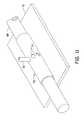
- FIG. 11is a perspective view of a tubular shield being prepared for use in an alternative fashion.
- FIG. 1there is shown an exemplary cardiac stimulator lead 10 that includes a flexible insulating sleeve 12 that has a proximal end 14 coupled to a connector 16 , and a distal end 18 coupled to a tip electrode 20 .
- the connector 16is designed to be inserted into a cardiac stimulator 22 , and is shown highly exaggerated in size relative to the cardiac stimulator 22 .
- the cardiac stimulator 22may be a pacemaker, a cardioverter/defibrillator, or other type of stimulator or a sensing instrument.
- the illustrated embodiment of the lead 10is bipolar.
- the distal end 18is provided with an electrode 24 located proximal to the tip electrode 20 .
- an electrode 24located proximal to the tip electrode 20 .
- a suture sleeve 26is slipped over the sleeve 12 . During implantation, the suture sleeve 26 is sewn to body tissue at the site of transvenous entry.
- the sleeve 12is a flexible tubular member that provides a robust, electrically insulating coupling between the connector 16 and the electrode 20 .
- the sleeve 12protects one or more fine gage conductor wires enclosed therein from body fluids and tissues, and is advantageously composed of a biocompatible, electrically insulating material, such as silicone, polyurethane, or like materials.
- the detailed structure of the electrode 20may be understood by referring now also to FIG. 2, which is an exploded side view of the electrode 20 and the end 18 of the sleeve positioned distal from the electrode 24 , and to FIG. 3 which is an end view of FIG. 2 .
- the electrode 20includes an electrode member 28 that has an elongated mandrel-like shank 30 that is provided with a set of external grooves or threads 32 at its proximal end 34 and terminates in an enlarged diameter tip 36 .
- the grooves 32may be formed integrally with the shank 30 or machined as a separate structure that may be welded or otherwise connected to the shank 30 .
- the transition from the shank 30 to the larger diameter tip 36defines a proximally facing annular shoulder 38 .
- the tip 36has a profile that tapers inwardly to a circular blunt or flat end surface 39 . Although the profile of the tip 36 is largely a matter of design discretion, an overall blunt profile of the distal end of the tip 36 reduces the potential for myocardial penetration and micro-dislodgment.
- the electrode member 28is advantageously fabricated from a biocompatible conductor or semiconductor material. Suitable materials include, for example, iridium oxide coated titanium, MP35N, stainless steel, platinum-iridium alloy consisting of approximately 90% platinum and 10% iridium, or some other biocompatible conducting metal, or a semiconductor material, such as silicon, or other semiconductor material. A portion of the electrode 20 may be composed of other than a conducting material so long as a conducting pathway is provided between the conductor wire 40 and the tip 36 .
- a conductor wire 40shown exploded from the electrode 20 , is slipped over the proximal end 34 of the shank 30 and spiraled around the grooves 32 when the lead 10 is assembled.
- the wire 40is depicted as a coiled metallic conductor wire that is individually insulated with a thin insulating jacket.
- An end 42 of the wire 40is stripped as shown to establish a good electrical contact with the exterior of the shank 30 .
- the end 42may also be spot welded by laser or other suitable techniques to the exterior of the shank 30 .
- the proximal end of the wire 40is coupled to the connector 16 shown in FIG. 1.
- a second conductor wire(not shown) is nested with the conductor wire 40 and is coupled distally to the annular electrode 24 and proximally to the connector 16 , and is positioned in a nested arrangement with the wire 40 within the sleeve 12 .
- the skilled artisanwill appreciate that other wiring arrangements may be incorporated in lieu of the individually insulated wire 40 and the companion wire (not shown). For example, commonly used coaxial wiring to arrangements may be incorporated where the individual wire coils are separated by an inner elongated tubular insulating sleeve.
- the distal end 18When the lead 10 is fully assembled, the distal end 18 is slipped over the shank 30 until a distally facing annular shoulder 44 on the distal end 18 abuts the proximally facing annular shoulder 38 of the tip 36 .
- a suitable medical grade, biocompatible adhesivemay be applied to the exterior of the shank 30 and/or the interior of the distal end 18 to secure the distal end 18 to the electrode member 28 .
- the adhesivemay be a silicone based adhesive, or one of a variety of commercially available two stage biocompatible adhesives.
- a low impedance electrode in a cardiac leadcan result in power consumption that is beyond the rate necessary for medically indicated cardiac stimulation and/or sensing.
- power supply depletionis inevitable in self-contained cells, unnecessary power consumption represents a real limit on battery life.
- the electrode 20may be fabricated with a higher impedance than would otherwise be possible in view of the conducting nature and structural requirements of the electrode 20 .
- a lead fitted with the electrode 20 in accordance with the present inventionmay reduce power consumption and prolong battery life for the cardiac stimulator 22 without sacrificing stimulation and/or sensing functions.
- FIGS. 2, 3 , 4 , and 5The impedance enhanced character of the electrode 20 may be understood now by referring to FIGS. 2, 3 , 4 , and 5 .
- FIG. 3is an end view
- FIGS. 4 and 5are sectional views taken, respectively, at sections 4 — 4 and 5 — 5 .
- a first portion 45 of the exterior of the electrode member 28 from the distal end of the grooves 32 to the end 39 of the tip 36is covered by a coating 46 composed of an electrically insulating material.
- a pre-selected second portion of the exterior of the electrode member 28 consisting of six peripherally spaced, circular spots 48 on the tip 36is re-exposed, as will be explained below.
- the coating 46substantially reduces the otherwise available conducting surface area of the electrode member 28 .
- the exposed circular areas or spots 48provide small conducting surfaces to contact and transmit electrical current between the electrode 20 and myocardial tissue.
- the reduced surface area of the electrode member 28 that may be exposed to myocardial tissuedramatically increases the impedance of the electrode 20 , thus lowering the power consumption of the lead 10 , and increasing the operating life of the power supply for the cardiac stimulator 22 shown in FIG. 1 .
- the first portion 45 of the electrode member 28includes all of the exterior of the electrode member 28 , save the exposed areas 48 , the grooves 32 , and the proximal end 34 .
- This configurationis illustrative as the desired increase in electrode impedance may be realized when the coating 46 is applied to at least the portion of the electrode member 28 that will be in contact with myocardial tissue. The skilled artisan will appreciate that enhanced impedance may also be achieved by covering a greater or a lesser amount of the exterior of the electrode member 28 .
- the grooves 32may also be coated if provision is made to establish a conducting connection between the stripped end 42 of the wire 40 and the grooves 32 .
- the coating 46may be applied only to the portion of the electrode member 28 that will contact myocardial tissue, i.e., the tip 36 , exclusive of the proximally facing annular shoulder 38 .
- FIG. 6which is a side view of an alternate embodiment of the electrode, now designated 20 ′
- FIGS. 6 and 7which are, respectively, an exploded side view and an end view of the electrode 20 ′.
- the tip 36 of the electrode member 28is provided with six peripherally spaced slots 50 that commonly intersect a circular bore 52 .
- the slots 50divide the tip 36 into a corresponding number of peripherally spaced projections 54 .
- Each projection 54has vertical sidewalls 58 , 60 , and 62 .
- Polymeric coatingssuch as parylene compounds, may be applied using a tool appropriate for the particular material.
- Parylene Cmay be applied using a parylene vacuum deposition system which delivers poly-para-xylylene into a vacuum chamber containing the targeted structure, e.g., the electrode member 28 .
- a tubular sleeve 70having a proximal end 80 and a distal end 82 , includes a pre-selected pattern of openings 74 corresponding to the pre-selected pattern of spots 48 .
- the sleeveshould be composed of a material that will withstand the removal process while protecting those portions of the coating 46 that are intended to remain intact.
- the tubeis comprised of medical grade silicon rubber. As illustrated in FIG.
- the sleeve 70is prepared by placing it on an anvil 72 or support table.
- a punch 76is driven through the sleeve to form a circumferential set of holes or openings 74 .
- the punchmay be a tube having a beveled cutting edge 78 .
- Other shapesare, of course, feasible.
- Driving the punch through the sleeve 70 into the anvil 72produces two diametrically opposed holes. This method produces an even number of openings, for example four or six openings, spaced around the circumference of the sleeve, as shown in FIG. 9 .
- the sleeveis placed over the tip electrode 20 as shown in FIG. 10 .
- Heptanemay be used to expand the silicon tube slightly, making it easier to place the sleeve on the electrode tip.
- the shieldis oriented so that the holes 74 are located over those areas where exposure of the conducting portion of the electrode is desired.
- the holescould be placed adjacent each segment 54 .
- a shieldwith an odd number of holes, or with a series of holes that are not symmetrically spaced around the circumference of the tube.
- a rod 88may be temporarily inserted in the sleeve 70 , as illustrated in FIG. 11 . DelronTM rods are suitable for this purpose. The punch 76 will then cut a hole in only one side of the sleeve at a time before being encountering the rod 88 .
Landscapes
- Health & Medical Sciences (AREA)
- Heart & Thoracic Surgery (AREA)
- Vascular Medicine (AREA)
- Cardiology (AREA)
- Engineering & Computer Science (AREA)
- Biomedical Technology (AREA)
- Nuclear Medicine, Radiotherapy & Molecular Imaging (AREA)
- Radiology & Medical Imaging (AREA)
- Life Sciences & Earth Sciences (AREA)
- Animal Behavior & Ethology (AREA)
- General Health & Medical Sciences (AREA)
- Public Health (AREA)
- Veterinary Medicine (AREA)
- Electrotherapy Devices (AREA)
Abstract
Description
This application is a continuation of U.S. patent application Ser. No. 09/366,400, filed on Aug. 3, 1999, now issued as U.S. Pat. No. 6,134,478, which in turn is a continuation-in-part of U.S. patent application Ser. No. 09/092,106, filed Jun. 5, 1998, now issued as U.S. Pat. No. 6,240,320, the specifications of which are incorporated herein by reference.
1. Field of the Invention
This invention relates generally to cardiac stimulator leads, and more particularly to a cardiac stimulator lead having an electrode selectively coated with an insulating material to define small conductive regions.
2. Description of the Related Art
Conventional cardiac stimulator systems consist of a cardiac stimulator and an elongated flexible cardiac lead that is connected proximally to a header structure on the cardiac stimulator and is implanted distally at one or more sites within the heart requiring cardiac stimulation or sensing. The cardiac stimulator is normally a pacemaker, a cardioverter/defibrillator, a sensing instrument, or some combination of these devices.
At the time of implantation, the distal end of a cardiac lead is inserted through an incision in the chest and manipulated by the physician to the site requiring electrical stimulation with the aid of a flexible stylet that is removed prior to closure. At the site requiring electrical stimulation, the distal end of the lead is anchored to the endocardium by an active mechanism, such as a screw-in electrode tip, or alternatively, by a passive mechanism, such as one or more radially spaced tines. The proximal end of the lead is then connected to the cardiac stimulator and the incision is closed.
Many implantable cardiac stimulators include a microprocessor or control circuit enclosed within a sealed housing or can. The circuit board controls the delivery of electric pulses to the lead and may perform various other functions. Power is supplied by an internal battery.
A conventional cardiac stimulator lead normally consists of an elongated, flexible, tubular, electrically insulating sleeve connected proximally to a connector that is adapted to couple to the header of a cardiac stimulator can and connected distally to a tubular tip electrode. One or more ring-type electrodes may be secured to the sleeve at various positions along the length of the sleeve. The proximal end of the lead sleeve is connected to the connector by application of various biocompatible adhesives to various portions of the connector and the sleeve. The tip electrode ordinarily consists of a tubular structure that has an increased diameter portion that forms an annular shoulder against which the distal end of the lead sleeve abuts. The exterior surface of the tubular structure is normally smooth as is the interior surface of the distal end of the lead sleeve. In multi-polar leads, one or more ring-type electrodes may be fitted over the sleeve.
To ensure that physical contact with the desired myocardial tissue is maintained after implantation, tip electrodes for most conventional leads are anchored to myocardial tissue by a fixation mechanism of one sort or another. In some leads, a corkscrew-like member projects from the tip electrode and penetrates the endocardium. In others, the electrode is fitted with one or more radially projecting tines that engage the trabeculae within the heart. Still others may employ both types of structures.
Most conventional tip electrodes serve at least two functions. First, tip electrodes provide a conducting member to convey electrical stimulation and sensing signals to and from myocardial tissue. Second, most tip electrodes provide structure to accommodate a fixation mechanism. Although conventional ring electrodes may be fitted with tines, most ring electrodes serve primarily as signal conductors.
The design of cardiac stimulation systems involves a balancing of a number of competing design considerations. Some of these include can size, lead tip dimensions and power consumption. Can miniaturization has been an important design goal since the first implantable pacemakers were introduced over thirty years ago. Smaller cans yield better post-operative comfort and cosmetic results for the patient. However, can miniaturization has required downsizing in storage batteries, which has, in turn, placed a premium on power consumption. Power consumption is of great importance because for a given level of power consumption, smaller batteries generally translate into shorter cardiac stimulator life spans and more frequent surgical procedures for the patient.
Some of the limitations associated with diminishing battery size have been offset by advances in cell chemistry. In addition, advances in pulse generation circuitry have dramatically increased the efficiency of power consumption. For example, many cardiac stimulators incorporate circuitry that automatically tailors pulse generation to the physiological demands of the patient.
However, despite advances in battery chemistry and circuitry, power consumption efficiency is still frequently limited by conventional lead electrode design. Most conventional lead electrodes operate as relatively low impedance, and thus, high current drawing devices. The low impedance levels are primarily a function of the relatively large conducting surface areas that these devices present to myocardial tissue. As noted above, the size of conventional lead electrodes is dictated in large part by mechanical considerations, such as the facilitation of fixation mechanisms. Furthermore, a certain degree of bluntness in a tip electrode is desirable to reduce the risk of myocardial perforation and micro-dislodgement, and to facilitate capture of the lead tip by post-implant developing fibrous tissue. Similarly, miniaturization of ring-type electrodes is generally limited by the size of the insulating lead sleeve and by the prevailing mechanical systems used to secure such ring-type electrodes to the lead sleeve.
As a result of these mechanical design considerations, current is often drawn by conventional low impedance electrodes at higher rates than necessary for appropriate stimulation. Some improvement in current drain may be realized by lowering the voltage output of the pulse generator. However, this technique is not possible in patients who require a threshold voltage for successful stimulation that is above the contemplated lowered output voltage. Thus, conventional lead electrode designs may represent an impediment to extended battery life.
In one conventional lead design, the distal end of the lead is provided with a distally projecting, small diameter circular electrode that has the potential to provide enhanced pacing impedance. However, this design may be prone to micro-dislodgment. Since the lead is provided with a single small conducting surface on the distal end of the lead, normal heart motion may cause the small conducting surface to momentarily lose contact with or micro-dislodge from myocardial tissue and disrupt the flow of pacing pulses.
The present invention is directed to overcoming or reducing the effects of one or more of the foregoing disadvantages.
In accordance with the present invention, a method of fabricating a high impedance cardiac lead electrode is provided. The method includes the steps of providing an electrode member and coating a first portion of the electrode member with an electrically insulating material and placing a tubular mask or shield over the electrode. Portions of the insulating material are removed to expose selected areas of the electrode.
The foregoing and other advantages of the invention will become apparent upon reading the following detailed description and upon reference to the drawings in which:
FIG. 1 is a pictorial view of an exemplary embodiment of a cardiac stimulator lead and a cardiac stimulator in accordance with the present invention;
FIG. 2 is an exploded side view of an exemplary cardiac lead electrode, sleeve and conductor in accordance with the present invention;
FIG. 3 is an end view of the electrode shown in FIG. 2 in accordance with the present invention;
FIG. 4 is a cross-sectional view of FIG. 2 taken atsection 4—4 in accordance with the present invention;
FIG. 5 is a cross-sectional view like FIG. 4 showing the electrode prior to coating with an insulating material in accordance with the present invention;
FIG. 6 is an exploded side view like FIG. 2 of an alternate exemplary electrode in accordance with the present invention;
FIG. 7 is an end view of the electrode depicted in FIG. 6 in accordance with the present invention;
FIG. 8 is a perspective view of a tubular shield being prepared for use in the method of the present invention;
FIG. 9 is a perspective view of the prepared shield of FIG. 8;
FIG. 10 is a cross sectional view of an electrode tip with shield; and
FIG. 11 is a perspective view of a tubular shield being prepared for use in an alternative fashion.
In the drawings described below, reference numerals are generally repeated where identical elements appear in more than one figure. Turning now to the drawings, and in particular to FIG. 1, there is shown an exemplarycardiac stimulator lead 10 that includes a flexible insulatingsleeve 12 that has aproximal end 14 coupled to aconnector 16, and adistal end 18 coupled to atip electrode 20. Theconnector 16 is designed to be inserted into acardiac stimulator 22, and is shown highly exaggerated in size relative to thecardiac stimulator 22. Thecardiac stimulator 22 may be a pacemaker, a cardioverter/defibrillator, or other type of stimulator or a sensing instrument. The illustrated embodiment of thelead 10 is bipolar. Accordingly, thedistal end 18 is provided with anelectrode 24 located proximal to thetip electrode 20. However, unipolar or other multi-polar arrangements are possible as well. Asuture sleeve 26 is slipped over thesleeve 12. During implantation, thesuture sleeve 26 is sewn to body tissue at the site of transvenous entry.
Thesleeve 12 is a flexible tubular member that provides a robust, electrically insulating coupling between theconnector 16 and theelectrode 20. Thesleeve 12 protects one or more fine gage conductor wires enclosed therein from body fluids and tissues, and is advantageously composed of a biocompatible, electrically insulating material, such as silicone, polyurethane, or like materials.
The detailed structure of theelectrode 20 may be understood by referring now also to FIG. 2, which is an exploded side view of theelectrode 20 and theend 18 of the sleeve positioned distal from theelectrode 24, and to FIG. 3 which is an end view of FIG.2. Theelectrode 20 includes anelectrode member 28 that has an elongated mandrel-like shank 30 that is provided with a set of external grooves orthreads 32 at itsproximal end 34 and terminates in anenlarged diameter tip 36. Thegrooves 32 may be formed integrally with theshank 30 or machined as a separate structure that may be welded or otherwise connected to theshank 30. The transition from theshank 30 to thelarger diameter tip 36 defines a proximally facingannular shoulder 38. Thetip 36 has a profile that tapers inwardly to a circular blunt orflat end surface 39. Although the profile of thetip 36 is largely a matter of design discretion, an overall blunt profile of the distal end of thetip 36 reduces the potential for myocardial penetration and micro-dislodgment.
Theelectrode member 28 is advantageously fabricated from a biocompatible conductor or semiconductor material. Suitable materials include, for example, iridium oxide coated titanium, MP35N, stainless steel, platinum-iridium alloy consisting of approximately 90% platinum and 10% iridium, or some other biocompatible conducting metal, or a semiconductor material, such as silicon, or other semiconductor material. A portion of theelectrode 20 may be composed of other than a conducting material so long as a conducting pathway is provided between theconductor wire 40 and thetip 36.
Aconductor wire 40, shown exploded from theelectrode 20, is slipped over theproximal end 34 of theshank 30 and spiraled around thegrooves 32 when thelead 10 is assembled. Thewire 40 is depicted as a coiled metallic conductor wire that is individually insulated with a thin insulating jacket. Anend 42 of thewire 40 is stripped as shown to establish a good electrical contact with the exterior of theshank 30. Theend 42 may also be spot welded by laser or other suitable techniques to the exterior of theshank 30. The proximal end of thewire 40 is coupled to theconnector 16 shown in FIG. 1. A second conductor wire (not shown) is nested with theconductor wire 40 and is coupled distally to theannular electrode 24 and proximally to theconnector 16, and is positioned in a nested arrangement with thewire 40 within thesleeve 12. The skilled artisan will appreciate that other wiring arrangements may be incorporated in lieu of the individually insulatedwire 40 and the companion wire (not shown). For example, commonly used coaxial wiring to arrangements may be incorporated where the individual wire coils are separated by an inner elongated tubular insulating sleeve.
When thelead 10 is fully assembled, thedistal end 18 is slipped over theshank 30 until a distally facingannular shoulder 44 on thedistal end 18 abuts the proximally facingannular shoulder 38 of thetip 36. A suitable medical grade, biocompatible adhesive may be applied to the exterior of theshank 30 and/or the interior of thedistal end 18 to secure thedistal end 18 to theelectrode member 28. The adhesive may be a silicone based adhesive, or one of a variety of commercially available two stage biocompatible adhesives.
As noted above, a low impedance electrode in a cardiac lead can result in power consumption that is beyond the rate necessary for medically indicated cardiac stimulation and/or sensing. Although power supply depletion is inevitable in self-contained cells, unnecessary power consumption represents a real limit on battery life. However, in accordance with the present invention, theelectrode 20 may be fabricated with a higher impedance than would otherwise be possible in view of the conducting nature and structural requirements of theelectrode 20. A lead fitted with theelectrode 20 in accordance with the present invention may reduce power consumption and prolong battery life for thecardiac stimulator 22 without sacrificing stimulation and/or sensing functions.
The impedance enhanced character of theelectrode 20 may be understood now by referring to FIGS. 2,3,4, and5. Relative to FIG. 2, FIG. 3 is an end view, and FIGS. 4 and 5 are sectional views taken, respectively, atsections 4—4 and5—5. Afirst portion 45 of the exterior of theelectrode member 28 from the distal end of thegrooves 32 to theend 39 of thetip 36 is covered by acoating 46 composed of an electrically insulating material. A pre-selected second portion of the exterior of theelectrode member 28 consisting of six peripherally spaced,circular spots 48 on thetip 36 is re-exposed, as will be explained below. Thecoating 46 substantially reduces the otherwise available conducting surface area of theelectrode member 28. The exposed circular areas or spots48 provide small conducting surfaces to contact and transmit electrical current between theelectrode 20 and myocardial tissue. The reduced surface area of theelectrode member 28 that may be exposed to myocardial tissue dramatically increases the impedance of theelectrode 20, thus lowering the power consumption of thelead 10, and increasing the operating life of the power supply for thecardiac stimulator 22 shown in FIG.1.
In the embodiment illustrated in FIGS. 2,3,4, and5, thefirst portion 45 of theelectrode member 28 includes all of the exterior of theelectrode member 28, save the exposedareas 48, thegrooves 32, and theproximal end 34. This configuration is illustrative as the desired increase in electrode impedance may be realized when thecoating 46 is applied to at least the portion of theelectrode member 28 that will be in contact with myocardial tissue. The skilled artisan will appreciate that enhanced impedance may also be achieved by covering a greater or a lesser amount of the exterior of theelectrode member 28. For example, thegrooves 32 may also be coated if provision is made to establish a conducting connection between the strippedend 42 of thewire 40 and thegrooves 32. Conversely, thecoating 46 may be applied only to the portion of theelectrode member 28 that will contact myocardial tissue, i.e., thetip 36, exclusive of the proximally facingannular shoulder 38.
The size, and configuration of the portion of the exterior of theelectrode member 28 that is exposed following application of thecoating 46 is largely a matter of design discretion and will depend on factors such as the electrical requirements of the cardiac stimulator and the medically indicated stimulation voltage, among others. For example, as shown in FIG. 6, which is a side view of an alternate embodiment of the electrode, now designated20′, may be understood by referring now to FIGS. 6 and 7, which are, respectively, an exploded side view and an end view of theelectrode 20′. In this embodiment, thetip 36 of theelectrode member 28 is provided with six peripherally spacedslots 50 that commonly intersect acircular bore 52. Theslots 50 divide thetip 36 into a corresponding number of peripherally spacedprojections 54. Eachprojection 54 hasvertical sidewalls
Polymeric coatings, such as parylene compounds, may be applied using a tool appropriate for the particular material. For example, Parylene C may be applied using a parylene vacuum deposition system which delivers poly-para-xylylene into a vacuum chamber containing the targeted structure, e.g., theelectrode member 28.
After the polymeric coating has been applied to the electrode, selected areas of the coating are removed to expose the conductive surface under the coating. This is accomplished by applying an abrasive process through a mask or shield. Plasma etching is a suitable abrasive process where a parylene compound is used for thecoating 46. Atubular sleeve 70, having aproximal end 80 and adistal end 82, includes a pre-selected pattern ofopenings 74 corresponding to the pre-selected pattern ofspots 48. The sleeve should be composed of a material that will withstand the removal process while protecting those portions of thecoating 46 that are intended to remain intact. Preferably, the tube is comprised of medical grade silicon rubber. As illustrated in FIG. 8, thesleeve 70 is prepared by placing it on ananvil 72 or support table. Apunch 76 is driven through the sleeve to form a circumferential set of holes oropenings 74. The punch may be a tube having abeveled cutting edge 78. Other shapes are, of course, feasible. Driving the punch through thesleeve 70 into theanvil 72 produces two diametrically opposed holes. This method produces an even number of openings, for example four or six openings, spaced around the circumference of the sleeve, as shown in FIG.9.
After theholes 74 have been punched in the sleeve, the sleeve is placed over thetip electrode 20 as shown in FIG.10. Heptane may be used to expand the silicon tube slightly, making it easier to place the sleeve on the electrode tip. The shield is oriented so that theholes 74 are located over those areas where exposure of the conducting portion of the electrode is desired. For example, in the hexagonally notched electrode tip illustrated in FIG.10 and described in connection with FIG.6 and FIG. 7 above, the holes could be placed adjacent eachsegment 54. After the sleeve is placed over the tip, thedistal end 82 of the sleeve is filled with medical grade adhesive, forming a complete shield around the tip. The tip is then exposed to plasma from aplasma source 86 to abrade the polymeric coating. After the polymeric coating has been removed in the desired locations, the sleeve is removed from the electrode tip.
It may also be desirable to provide a shield with an odd number of holes, or with a series of holes that are not symmetrically spaced around the circumference of the tube. For instance, it may be desired to provide conducting areas on only three of the sixsegments 54 of the electrode tip of FIG.6. In such cases, arod 88 may be temporarily inserted in thesleeve 70, as illustrated in FIG.11. Delron™ rods are suitable for this purpose. Thepunch 76 will then cut a hole in only one side of the sleeve at a time before being encountering therod 88.
While the invention may be susceptible to various modifications and alternative forms, specific embodiments have been shown by way of example in the drawings and have been described in detail herein. However, it should be understood that the invention is not intended to be limited to the particular forms disclosed. Rather, the invention is to cover all modifications, equivalents and alternatives falling within the spirit and scope of the invention as defined by the following appended claims.
Claims (20)
1. An apparatus, comprising:
an electrode;
an electrically insulative coating on the electrode;
a tubular sleeve with one or more radial openings, wherein the electrode is partially exposed through the one or more radial openings.
2. The apparatus ofclaim 1 , including an abrasion source, where the abrasion source abrades the electrically insulative coating exposed through the openings of the tubular sleeve to expose the electrode and enhance the impedance of the electrode.
3. The apparatus ofclaim 2 , where the abrasion source is a plasma source.
4. The apparatus ofclaim 1 , where the tubular sleeve is medical grade silicon rubber.
5. The apparatus ofclaim 1 , wherein the electrically insulating material comprises parylene C.
6. The apparatus ofclaim 1 , where electrode has an iridium oxide coating.
7. The apparatus as recited inclaim 11 , wherein the tubular sleeve includes a plurality of radically spaced circular openings.
8. An apparatus comprising:
a lead including a lead body extending from a body proximal end to a body distal end;
an electrode coupled associated with the lead body adjacent to the body distal end;
a connector coupled with the lead body at the body proximal end;
at least one conductor electrically coupled with the connector and the electrode;
a polymeric coating disposed over a portion of the electrode; and
a tubular sleeve including one or more openings therein, the tubular sleeve configured to be temporarily and removably disposed over the lead body and the polymeric coating.
9. The apparatus as recited inclaim 8 , wherein the openings are symmetrically spaced about the circumference of the sleeve.
10. The apparatus as recited inclaim 8 , wherein the electrode includes a plurality of slots therein, the slots defining peripherally spaced projection therebetween, and the polymeric coating is disposed over the projections.
11. The apparatus as recited inclaim 8 , wherein the tubular sleeve includes two or more openings therein, and the openings and asymmetrically spaced about the circumference of the tubular sleeve.
12. The apparatus as recited inclaim 8 , further comprising a means for temporarily placing the tubular sleeve over the polymeric coating.
13. The apparatus as recited inclaim 8 , wherein the electrode includes a tubular shank having external grooves thereon, and the conductor is spiraled within the external grooves.
14. The apparatus as recited inclaim 8 , further comprising a means for forming openings in the tubular sleeve.
15. The apparatus as recited inclaim 8 , wherein the electrode includes a plurality of peripherally spaced openings, where the polymeric coating has been removed from the electrode to form the plurality of openings.
16. An apparatus comprising:
a lead including a lead body extending from a body proximal end to a body distal end;
an electrode coupled associated with the lead body adjacent to the body distal end;
a connector coupled with the lead body at the body proximal end;
at least one conductor electrically coupled with the connector and the electrode;
a polymeric coating disposed over a portion of the electrode; and
a means for selectively removing a portion of the polymeric coating, including a means for selectively blocking one or more portions of the polymeric coating.
17. The apparatus as recited inclaim 16 , wherein the means for selectively removing a portion of the polymeric includes an abrasion source.
18. The apparatus as recited inclaim 16 , wherein the abrasion source comprises a plasma source.
19. The apparatus as recited inclaim 16 , further comprising a means for temporarily placing the tubular sleeve over the polymeric coating.
20. The apparatus as recited inclaim 16 , wherein the electrode includes a tubular shank having external grooves thereon, and the conductor is spiraled within the external grooves.
Priority Applications (1)
| Application Number | Priority Date | Filing Date | Title |
|---|---|---|---|
| US09/638,963US6526321B1 (en) | 1998-06-05 | 2000-08-15 | Method for making cardiac leads with zone insulated electrodes |
Applications Claiming Priority (3)
| Application Number | Priority Date | Filing Date | Title |
|---|---|---|---|
| US09/092,106US6240320B1 (en) | 1998-06-05 | 1998-06-05 | Cardiac lead with zone insulated electrodes |
| US09/366,400US6134478A (en) | 1998-06-05 | 1999-08-03 | Method for making cardiac leads with zone insulated electrodes |
| US09/638,963US6526321B1 (en) | 1998-06-05 | 2000-08-15 | Method for making cardiac leads with zone insulated electrodes |
Related Parent Applications (1)
| Application Number | Title | Priority Date | Filing Date |
|---|---|---|---|
| US09/366,400ContinuationUS6134478A (en) | 1998-06-05 | 1999-08-03 | Method for making cardiac leads with zone insulated electrodes |
Publications (1)
| Publication Number | Publication Date |
|---|---|
| US6526321B1true US6526321B1 (en) | 2003-02-25 |
Family
ID=23442853
Family Applications (2)
| Application Number | Title | Priority Date | Filing Date |
|---|---|---|---|
| US09/366,400Expired - LifetimeUS6134478A (en) | 1998-06-05 | 1999-08-03 | Method for making cardiac leads with zone insulated electrodes |
| US09/638,963Expired - LifetimeUS6526321B1 (en) | 1998-06-05 | 2000-08-15 | Method for making cardiac leads with zone insulated electrodes |
Family Applications Before (1)
| Application Number | Title | Priority Date | Filing Date |
|---|---|---|---|
| US09/366,400Expired - LifetimeUS6134478A (en) | 1998-06-05 | 1999-08-03 | Method for making cardiac leads with zone insulated electrodes |
Country Status (3)
| Country | Link |
|---|---|
| US (2) | US6134478A (en) |
| AU (1) | AU6514000A (en) |
| WO (1) | WO2001008744A1 (en) |
Cited By (58)
| Publication number | Priority date | Publication date | Assignee | Title |
|---|---|---|---|---|
| US20020183817A1 (en)* | 2000-12-07 | 2002-12-05 | Paul Van Venrooij | Directional brain stimulation and recording leads |
| US20030220676A1 (en)* | 2002-05-21 | 2003-11-27 | John R. Helland | Electrode arrangements for body implantable pacing and sensing leads |
| US20030229387A1 (en)* | 2000-02-08 | 2003-12-11 | Medtronic, Inc. | Surgical lead body |
| US20050038489A1 (en)* | 2003-08-14 | 2005-02-17 | Grill Warren M. | Electrode array for use in medical stimulation and methods thereof |
| US20050222660A1 (en)* | 2004-03-30 | 2005-10-06 | Cardiac Pacemakers, Inc. | Electrode and insulation assembly for a lead and method therefor |
| US20060122682A1 (en)* | 2004-12-03 | 2006-06-08 | Sommer John L | High impedance active fixation electrode of an electrical medical lead |
| US20060168805A1 (en)* | 2005-01-31 | 2006-08-03 | Michael Hegland | Method of manufacturing a medical lead |
| US20070092591A1 (en)* | 2005-10-24 | 2007-04-26 | Cyberonics, Inc. | Vacuum mandrel for use in fabricating an implantable electrode |
| US20070142879A1 (en)* | 2005-12-20 | 2007-06-21 | The Cleveland Clinic Foundation | Apparatus and method for modulating the baroreflex system |
| US7489971B1 (en) | 2004-06-05 | 2009-02-10 | Advanced Neuromodulation Systems, Inc. | Notched electrode for electrostimulation lead |
| US20090138058A1 (en)* | 2004-12-17 | 2009-05-28 | Cardiac Pacemakers, Inc. | Mri operation modes for implantable medical devices |
| US7561915B1 (en) | 2004-12-17 | 2009-07-14 | Cardiac Pacemakers, Inc. | MRI system having implantable device safety features |
| US20090192580A1 (en)* | 2008-01-28 | 2009-07-30 | Shrojalkumar Desai | Medical electrical lead with biocompatible lead body coating |
| US20090192577A1 (en)* | 2008-01-28 | 2009-07-30 | Shrojalkumar Desai | Medical electrical lead with coated conductor |
| US20090312825A1 (en)* | 2008-06-17 | 2009-12-17 | W.C. Heraeus Gmbh | Selective parylene coating for cardiac pacemaker electrodes |
| US20100001387A1 (en)* | 2007-03-23 | 2010-01-07 | Fujitsu Limited | Electronic device, electronic apparatus mounted with electronic device, article equipped with electronic device and method of producing electronic device |
| US20100010602A1 (en)* | 2006-11-30 | 2010-01-14 | Wedan Steven R | Rf rejecting lead |
| US20100087892A1 (en)* | 2008-10-02 | 2010-04-08 | Stubbs Scott R | Implantable medical device responsive to mri induced capture threshold changes |
| US20100211123A1 (en)* | 2009-02-19 | 2010-08-19 | Stubbs Scott R | Systems and methods for providing arrhythmia therapy in mri environments |
| US20100234929A1 (en)* | 2009-03-12 | 2010-09-16 | Torsten Scheuermann | Thin profile conductor assembly for medical device leads |
| US20100331936A1 (en)* | 2009-06-26 | 2010-12-30 | Christopher Perrey | Medical device lead including a unifilar coil with improved torque transmission capacity and reduced mri heating |
| DE102009033770A1 (en)* | 2009-07-17 | 2011-01-20 | W.C. Heraeus Gmbh | Connection between stimulation electrode and conduction coil |
| US20110015710A1 (en)* | 2009-07-17 | 2011-01-20 | W. C. Heraeus Gmbh | Crimp connection between stimulation electrode and conduction coil |
| US20110015709A1 (en)* | 2009-07-17 | 2011-01-20 | W. C. Heraeus Gmbh | Connection element for conduction coil |
| US20110047795A1 (en)* | 2009-09-01 | 2011-03-03 | Kevin Turner | Medical leads with segmented electrodes and methods of fabrication thereof |
| US20110087299A1 (en)* | 2009-10-08 | 2011-04-14 | Masoud Ameri | Medical device lead including a flared conductive coil |
| US20110160818A1 (en)* | 2009-12-30 | 2011-06-30 | Roger Struve | Mri-conditionally safe medical device lead |
| US20110160829A1 (en)* | 2009-12-31 | 2011-06-30 | Foster Arthur J | Mri conditionally safe lead with multi-layer conductor |
| US20110160828A1 (en)* | 2009-12-31 | 2011-06-30 | Foster Arthur J | Mri conditionally safe lead with low-profile multi-layer conductor for longitudinal expansion |
| US8032228B2 (en) | 2007-12-06 | 2011-10-04 | Cardiac Pacemakers, Inc. | Method and apparatus for disconnecting the tip electrode during MRI |
| US8086321B2 (en) | 2007-12-06 | 2011-12-27 | Cardiac Pacemakers, Inc. | Selectively connecting the tip electrode during therapy for MRI shielding |
| US8103360B2 (en) | 2008-05-09 | 2012-01-24 | Foster Arthur J | Medical lead coil conductor with spacer element |
| US8160717B2 (en) | 2008-02-19 | 2012-04-17 | Cardiac Pacemakers, Inc. | Model reference identification and cancellation of magnetically-induced voltages in a gradient magnetic field |
| US8244346B2 (en) | 2008-02-06 | 2012-08-14 | Cardiac Pacemakers, Inc. | Lead with MRI compatible design features |
| US8311637B2 (en) | 2008-02-11 | 2012-11-13 | Cardiac Pacemakers, Inc. | Magnetic core flux canceling of ferrites in MRI |
| US8565874B2 (en) | 2009-12-08 | 2013-10-22 | Cardiac Pacemakers, Inc. | Implantable medical device with automatic tachycardia detection and control in MRI environments |
| US8666512B2 (en) | 2011-11-04 | 2014-03-04 | Cardiac Pacemakers, Inc. | Implantable medical device lead including inner coil reverse-wound relative to shocking coil |
| US8731685B2 (en) | 2007-12-06 | 2014-05-20 | Cardiac Pacemakers, Inc. | Implantable lead having a variable coil conductor pitch |
| US8825181B2 (en) | 2010-08-30 | 2014-09-02 | Cardiac Pacemakers, Inc. | Lead conductor with pitch and torque control for MRI conditionally safe use |
| US8825179B2 (en) | 2012-04-20 | 2014-09-02 | Cardiac Pacemakers, Inc. | Implantable medical device lead including a unifilar coiled cable |
| US8954168B2 (en) | 2012-06-01 | 2015-02-10 | Cardiac Pacemakers, Inc. | Implantable device lead including a distal electrode assembly with a coiled component |
| US8958889B2 (en) | 2012-08-31 | 2015-02-17 | Cardiac Pacemakers, Inc. | MRI compatible lead coil |
| US8983623B2 (en) | 2012-10-18 | 2015-03-17 | Cardiac Pacemakers, Inc. | Inductive element for providing MRI compatibility in an implantable medical device lead |
| US9242088B2 (en) | 2013-11-22 | 2016-01-26 | Simon Fraser University | Apparatus and methods for assisted breathing by transvascular nerve stimulation |
| US9254380B2 (en) | 2009-10-19 | 2016-02-09 | Cardiac Pacemakers, Inc. | MRI compatible tachycardia lead |
| US9504821B2 (en) | 2014-02-26 | 2016-11-29 | Cardiac Pacemakers, Inc. | Construction of an MRI-safe tachycardia lead |
| US10039920B1 (en) | 2017-08-02 | 2018-08-07 | Lungpacer Medical, Inc. | Systems and methods for intravascular catheter positioning and/or nerve stimulation |
| US10293164B2 (en) | 2017-05-26 | 2019-05-21 | Lungpacer Medical Inc. | Apparatus and methods for assisted breathing by transvascular nerve stimulation |
| US10391314B2 (en) | 2014-01-21 | 2019-08-27 | Lungpacer Medical Inc. | Systems and related methods for optimization of multi-electrode nerve pacing |
| US10406367B2 (en) | 2012-06-21 | 2019-09-10 | Lungpacer Medical Inc. | Transvascular diaphragm pacing system and methods of use |
| US10512772B2 (en) | 2012-03-05 | 2019-12-24 | Lungpacer Medical Inc. | Transvascular nerve stimulation apparatus and methods |
| US10561843B2 (en) | 2007-01-29 | 2020-02-18 | Lungpacer Medical, Inc. | Transvascular nerve stimulation apparatus and methods |
| US10940308B2 (en) | 2017-08-04 | 2021-03-09 | Lungpacer Medical Inc. | Systems and methods for trans-esophageal sympathetic ganglion recruitment |
| US10987511B2 (en) | 2018-11-08 | 2021-04-27 | Lungpacer Medical Inc. | Stimulation systems and related user interfaces |
| US11357979B2 (en) | 2019-05-16 | 2022-06-14 | Lungpacer Medical Inc. | Systems and methods for sensing and stimulation |
| US11771900B2 (en) | 2019-06-12 | 2023-10-03 | Lungpacer Medical Inc. | Circuitry for medical stimulation systems |
| US11883658B2 (en) | 2017-06-30 | 2024-01-30 | Lungpacer Medical Inc. | Devices and methods for prevention, moderation, and/or treatment of cognitive injury |
| US12029903B2 (en) | 2017-12-11 | 2024-07-09 | Lungpacer Medical Inc. | Systems and methods for strengthening a respiratory muscle |
Families Citing this family (81)
| Publication number | Priority date | Publication date | Assignee | Title |
|---|---|---|---|---|
| EP1080684A3 (en)* | 1999-09-03 | 2003-04-16 | Nihon Kohden Corporation | Sensor for measuring a gas or ion concentration in living tissue |
| US6925328B2 (en) | 2000-04-20 | 2005-08-02 | Biophan Technologies, Inc. | MRI-compatible implantable device |
| US8527046B2 (en) | 2000-04-20 | 2013-09-03 | Medtronic, Inc. | MRI-compatible implantable device |
| US20020116028A1 (en) | 2001-02-20 | 2002-08-22 | Wilson Greatbatch | MRI-compatible pacemaker with pulse carrying photonic catheter providing VOO functionality |
| US6829509B1 (en) | 2001-02-20 | 2004-12-07 | Biophan Technologies, Inc. | Electromagnetic interference immune tissue invasive system |
| US6731979B2 (en) | 2001-08-30 | 2004-05-04 | Biophan Technologies Inc. | Pulse width cardiac pacing apparatus |
| US7054686B2 (en) | 2001-08-30 | 2006-05-30 | Biophan Technologies, Inc. | Pulsewidth electrical stimulation |
| US6988001B2 (en) | 2001-10-31 | 2006-01-17 | Biophan Technologies, Inc. | Hermetic component housing for photonic catheter |
| US6968236B2 (en) | 2002-01-28 | 2005-11-22 | Biophan Technologies, Inc. | Ceramic cardiac electrodes |
| US6711440B2 (en) | 2002-04-11 | 2004-03-23 | Biophan Technologies, Inc. | MRI-compatible medical device with passive generation of optical sensing signals |
| US6725092B2 (en) | 2002-04-25 | 2004-04-20 | Biophan Technologies, Inc. | Electromagnetic radiation immune medical assist device adapter |
| US7860570B2 (en) | 2002-06-20 | 2010-12-28 | Boston Scientific Neuromodulation Corporation | Implantable microstimulators and methods for unidirectional propagation of action potentials |
| US6925322B2 (en) | 2002-07-25 | 2005-08-02 | Biophan Technologies, Inc. | Optical MRI catheter system |
| EP1622677B1 (en)* | 2003-04-02 | 2013-09-18 | Medtronic, Inc. | Device for preventing magnetic-device imaging induced damage |
| US20040199069A1 (en)* | 2003-04-02 | 2004-10-07 | Connelly Patrick R. | Device and method for preventing magnetic resonance imaging induced damage |
| WO2007022192A2 (en)* | 2005-08-15 | 2007-02-22 | Synecor, Llc | Electrodes for implantable medical devices |
| US7583999B2 (en) | 2006-07-31 | 2009-09-01 | Cranial Medical Systems, Inc. | Multi-channel connector for brain stimulation system |
| US8321025B2 (en) | 2006-07-31 | 2012-11-27 | Cranial Medical Systems, Inc. | Lead and methods for brain monitoring and modulation |
| US8359107B2 (en) | 2008-10-09 | 2013-01-22 | Boston Scientific Neuromodulation Corporation | Electrode design for leads of implantable electric stimulation systems and methods of making and using |
| AU2010236196B2 (en) | 2009-04-16 | 2015-11-12 | Boston Scientific Neuromodulation Corporation | Deep brain stimulation current steering with split electrodes |
| US8887387B2 (en) | 2009-07-07 | 2014-11-18 | Boston Scientific Neuromodulation Corporation | Methods of manufacture of leads with a radially segmented electrode array |
| US8875391B2 (en) | 2009-07-07 | 2014-11-04 | Boston Scientific Neuromodulation Corporation | Methods for making leads with radially-aligned segmented electrodes for electrical stimulation systems |
| US8295944B2 (en) | 2009-11-30 | 2012-10-23 | Boston Scientific Neuromodulation Corporation | Electrode array with electrodes having cutout portions and methods of making the same |
| US8874232B2 (en)* | 2009-11-30 | 2014-10-28 | Boston Scientific Neuromodulation Corporation | Electrode array having concentric split ring electrodes and methods of making the same |
| US8391985B2 (en) | 2009-11-30 | 2013-03-05 | Boston Scientific Neuromodulation Corporation | Electrode array having concentric windowed cylinder electrodes and methods of making the same |
| US8788063B2 (en) | 2009-11-30 | 2014-07-22 | Boston Scientific Neuromodulation Corporation | Electrode array having a rail system and methods of manufacturing the same |
| US8571665B2 (en)* | 2010-03-23 | 2013-10-29 | Boston Scientific Neuromodulation Corporation | Helical radial spacing of contacts on a cylindrical lead |
| EP2582425B1 (en) | 2010-06-18 | 2018-04-04 | Boston Scientific Neuromodulation Corporation | Method of making electrode array having embedded electrodes |
| US9675795B2 (en) | 2010-07-16 | 2017-06-13 | Boston Scientific Neuromodulation Corporation | Systems and methods for radial steering of electrode arrays |
| US8583237B2 (en) | 2010-09-13 | 2013-11-12 | Cranial Medical Systems, Inc. | Devices and methods for tissue modulation and monitoring |
| AU2011305914B2 (en) | 2010-09-21 | 2016-05-12 | Boston Scientific Neuromodulation Corporation | Systems and methods for making and using radially-aligned segmented electrodes for leads of electrical stimulation systems |
| CA2822343A1 (en) | 2010-12-23 | 2012-06-28 | Boston Scientific Neuromodulation Corporation | Methods for making leads with segmented electrodes for electrical stimulation systems |
| US8700179B2 (en) | 2011-02-02 | 2014-04-15 | Boston Scientific Neuromodulation Corporation | Leads with spiral of helical segmented electrode arrays and methods of making and using the leads |
| ES2801326T3 (en) | 2011-02-08 | 2021-01-11 | Boston Scient Neuromodulation Corp | Spirally arranged lead wires with segmented electrodes and lead wire manufacturing and use procedures |
| JP2014511227A (en) | 2011-02-08 | 2014-05-15 | ボストン サイエンティフィック ニューロモデュレイション コーポレイション | Method of manufacturing a lead having segmented electrodes for an electrical stimulation system |
| US20120203316A1 (en) | 2011-02-08 | 2012-08-09 | Boston Scientific Neuromodulation Corporation | Leads with segmented electrodes for electrical stimulation of planar regions and methods of making and using |
| WO2013112905A1 (en) | 2012-01-26 | 2013-08-01 | Boston Scientific Neuromodulation Corporation | Systems and methods for identifying the circumferential positioning of electrodes of leads for electrical stimulation systems |
| WO2013148092A1 (en) | 2012-03-30 | 2013-10-03 | Boston Scientific Neuromodulation Corporation | Leads with x-ray fluorescent capsules for electrode identification and methods of manufacture and use |
| EP3111989B1 (en) | 2012-06-01 | 2021-09-01 | Boston Scientific Neuromodulation Corporation | Leads with tip electrode for electrical stimulation systems |
| US8897891B2 (en) | 2012-08-03 | 2014-11-25 | Boston Scientific Neuromodulation Corporation | Leads with electrode carrier for segmented electrodes and methods of making and using |
| WO2014186122A2 (en) | 2013-05-15 | 2014-11-20 | Boston Scientific Neuromodulation Corporation | Systems and methods for making and using tip electrodes for leads of electrical stimulation systems |
| WO2014193762A2 (en) | 2013-05-31 | 2014-12-04 | Boston Scientific Neuromodulation Corporation | Leads containing segmented electrodes with non-perpendicular legs and methods of making and using |
| CN105263567A (en) | 2013-05-31 | 2016-01-20 | 波士顿科学神经调制公司 | Segmented electrode leads formed from pre-electrodes with alignment features and mehods of making and using the leads |
| AU2014274414A1 (en) | 2013-05-31 | 2015-11-19 | Boston Scientific Neuromodulation Corporation | Leads with segmented electrodes and methods of making the leads |
| JP2016519984A (en) | 2013-05-31 | 2016-07-11 | ボストン サイエンティフィック ニューロモデュレイション コーポレイション | Segment electrode lead formed from a pre-electrode having a recess or a hole, and a method for manufacturing the same |
| JP6072986B2 (en) | 2013-07-12 | 2017-02-01 | ボストン サイエンティフィック ニューロモデュレイション コーポレイション | Lead having segment electrode and method of manufacturing and using lead |
| AU2014293477A1 (en) | 2013-07-22 | 2016-01-28 | Boston Scientific Neuromodulation Corporation | Methods of manufacturing molded segmented electrode leads |
| US9089689B2 (en) | 2013-08-30 | 2015-07-28 | Boston Scientific Neuromodulation Corporation | Methods of making segmented electrode leads using flanged carrier |
| WO2015084745A1 (en) | 2013-12-02 | 2015-06-11 | Boston Scientific Neuromodulation Corporation | Electrical stimulation leads with helically arranged electrodes and methods for their manufacture |
| WO2015192058A1 (en) | 2014-06-13 | 2015-12-17 | Boston Scientific Neuromodulation Corporation | Leads with electrode carriers for segmented electrodes and methods of making and using |
| US9770598B2 (en) | 2014-08-29 | 2017-09-26 | Boston Scientific Neuromodulation Corporation | Systems and methods for making and using improved connector contacts for electrical stimulation systems |
| US10743960B2 (en) | 2014-09-04 | 2020-08-18 | AtaCor Medical, Inc. | Cardiac arrhythmia treatment devices and delivery |
| US10328268B2 (en) | 2014-09-04 | 2019-06-25 | AtaCor Medical, Inc. | Cardiac pacing |
| US9604068B2 (en) | 2014-11-10 | 2017-03-28 | Boston Scientific Neuromodulation Corporation | Systems and methods for making and using improved connector contacts for electrical stimulation systems |
| US9561362B2 (en) | 2014-11-10 | 2017-02-07 | Boston Scientific Neuromodulation Corporation | Systems and methods for making and using improved contact arrays for electrical stimulation systems |
| US11097109B2 (en) | 2014-11-24 | 2021-08-24 | AtaCor Medical, Inc. | Cardiac pacing sensing and control |
| EP3229891B1 (en) | 2015-02-06 | 2019-08-14 | Boston Scientific Neuromodulation Corporation | Systems with improved contact arrays for electrical stimulation systems |
| WO2016164361A1 (en) | 2015-04-10 | 2016-10-13 | Boston Scientific Neuromodulation Corporation | Systems and methods for making and using improved contact arrays for electrical stimulation systems |
| US9656093B2 (en) | 2015-07-16 | 2017-05-23 | Boston Scientific Neuromodulation Corporation | Systems and methods for making and using connector contact arrays for electrical stimulation systems |
| US9956394B2 (en) | 2015-09-10 | 2018-05-01 | Boston Scientific Neuromodulation Corporation | Connectors for electrical stimulation systems and methods of making and using |
| US10413737B2 (en) | 2015-09-25 | 2019-09-17 | Boston Scientific Neuromodulation Corporation | Systems and methods for providing therapy using electrical stimulation to disrupt neuronal activity |
| US10342983B2 (en) | 2016-01-14 | 2019-07-09 | Boston Scientific Neuromodulation Corporation | Systems and methods for making and using connector contact arrays for electrical stimulation systems |
| US10201713B2 (en) | 2016-06-20 | 2019-02-12 | Boston Scientific Neuromodulation Corporation | Threaded connector assembly and methods of making and using the same |
| US10307602B2 (en) | 2016-07-08 | 2019-06-04 | Boston Scientific Neuromodulation Corporation | Threaded connector assembly and methods of making and using the same |
| US10543374B2 (en) | 2016-09-30 | 2020-01-28 | Boston Scientific Neuromodulation Corporation | Connector assemblies with bending limiters for electrical stimulation systems and methods of making and using same |
| US10576269B2 (en) | 2017-01-03 | 2020-03-03 | Boston Scientific Neuromodulation Corporation | Force-decoupled and strain relieving lead and methods of making and using |
| US10905871B2 (en) | 2017-01-27 | 2021-02-02 | Boston Scientific Neuromodulation Corporation | Lead assemblies with arrangements to confirm alignment between terminals and contacts |
| US10814136B2 (en) | 2017-02-28 | 2020-10-27 | Boston Scientific Neuromodulation Corporation | Toolless connector for latching stimulation leads and methods of making and using |
| US10603499B2 (en) | 2017-04-07 | 2020-03-31 | Boston Scientific Neuromodulation Corporation | Tapered implantable lead and connector interface and methods of making and using |
| WO2019023067A1 (en) | 2017-07-25 | 2019-01-31 | Boston Scientific Neuromodulation Corporation | Systems and methods for making and using an enhanced connector of an electrical stimulation system |
| US11045656B2 (en) | 2017-09-15 | 2021-06-29 | Boston Scientific Neuromodulation Corporation | Biased lead connector for operating room cable assembly and methods of making and using |
| US10639485B2 (en) | 2017-09-15 | 2020-05-05 | Boston Scientific Neuromodulation Corporation | Actuatable lead connector for an operating room cable assembly and methods of making and using |
| US11139603B2 (en) | 2017-10-03 | 2021-10-05 | Boston Scientific Neuromodulation Corporation | Connectors with spring contacts for electrical stimulation systems and methods of making and using same |
| US11103712B2 (en) | 2018-01-16 | 2021-08-31 | Boston Scientific Neuromodulation Corporation | Connector assemblies with novel spacers for electrical stimulation systems and methods of making and using same |
| US11172959B2 (en) | 2018-05-02 | 2021-11-16 | Boston Scientific Neuromodulation Corporation | Long, flexible sheath and lead blank and systems and methods of making and using |
| US11052259B2 (en) | 2018-05-11 | 2021-07-06 | Boston Scientific Neuromodulation Corporation | Connector assembly for an electrical stimulation system and methods of making and using |
| US11167128B2 (en) | 2018-11-16 | 2021-11-09 | Boston Scientific Neuromodulation Corporation | Directional electrical stimulation leads, systems and methods for spinal cord stimulation |
| US11357992B2 (en) | 2019-05-03 | 2022-06-14 | Boston Scientific Neuromodulation Corporation | Connector assembly for an electrical stimulation system and methods of making and using |
| EP4527449A3 (en) | 2019-05-29 | 2025-04-30 | Atacor Medical, Inc. | Implantable electrical leads and associated delivery systems |
| JP7688170B2 (en) | 2021-02-25 | 2025-06-03 | ボストン サイエンティフィック ニューロモデュレイション コーポレイション | Method and system for deep brain stimulation of the nucleus basalis of meynert |
| US12343547B2 (en) | 2021-08-19 | 2025-07-01 | Boston Scientific Neuromodulation Corporation | Connectors for an electrical stimulation system and methods of making and using |
Citations (69)
| Publication number | Priority date | Publication date | Assignee | Title |
|---|---|---|---|---|
| FR2225179A1 (en) | 1973-04-14 | 1974-11-08 | Lagergren Hans | |
| US4026303A (en) | 1975-11-17 | 1977-05-31 | Vitatron Medical B.V. | Endocardial pacing electrode |
| US4044774A (en) | 1976-02-23 | 1977-08-30 | Medtronic, Inc. | Percutaneously inserted spinal cord stimulation lead |
| EP0054781A1 (en) | 1980-12-23 | 1982-06-30 | Kontron Ag | Implantable electrode |
| US4502492A (en) | 1983-04-28 | 1985-03-05 | Medtronic, Inc. | Low-polarization low-threshold electrode |
| EP0191238A1 (en) | 1985-01-16 | 1986-08-20 | Intermedics, Inc. | Pacemaker lead with enhanced sensitivity |
| US4611604A (en) | 1983-01-11 | 1986-09-16 | Siemens Aktiengesellschaft | Bipolar electrode for medical applications |
| US4630611A (en) | 1981-02-02 | 1986-12-23 | Medtronic, Inc. | Orthogonally-sensing lead |
| US4649937A (en) | 1985-01-28 | 1987-03-17 | Cordis Corporation | Etched grooved electrode for pacing lead and method for making same |
| US4760852A (en) | 1985-09-09 | 1988-08-02 | Siemens Aktiengesellschaft | Heart pacemaker electrode having two portions of different conductive properties for stimulating and sensing |
| US4765341A (en) | 1981-06-22 | 1988-08-23 | Mieczyslaw Mirowski | Cardiac electrode with attachment fin |
| EP0296001A1 (en) | 1987-06-04 | 1988-12-21 | Ela Medical | Conducting extremites of cardiac stimulation electrodes |
| US5029585A (en)* | 1989-07-14 | 1991-07-09 | Baxter International Inc. | Comformable intralumen electrodes |
| WO1993000130A1 (en) | 1991-06-20 | 1993-01-07 | Possis Medical, Inc. | Cardiac lead with retractable fixators |
| US5222506A (en) | 1991-07-29 | 1993-06-29 | Medtronic, Inc. | Implantable medical lead with electrical cross-over adaptor |
| US5231996A (en) | 1992-01-28 | 1993-08-03 | Medtronic, Inc. | Removable endocardial lead |
| US5306292A (en)* | 1992-05-25 | 1994-04-26 | Siemens-Elema Ab | Heart stimulation apparatus |
| US5324322A (en) | 1992-04-20 | 1994-06-28 | Case Western Reserve University | Thin film implantable electrode and method of manufacture |
| US5405375A (en) | 1994-01-21 | 1995-04-11 | Incontrol, Inc. | Combined mapping, pacing, and defibrillating catheter |
| US5405373A (en)* | 1993-02-12 | 1995-04-11 | Siemens-Elema Ab | Electrode device for intracorporeal tissue stimulation |
| US5456254A (en) | 1991-02-15 | 1995-10-10 | Cardiac Pathways Corp | Flexible strip assembly having insulating layer with conductive pads exposed through insulating layer and device utilizing the same |
| US5514173A (en) | 1993-01-05 | 1996-05-07 | Rebell; Allan K. | Active fixation lead with a dual-pitch, free spinning compound screw |
| US5515848A (en) | 1991-10-22 | 1996-05-14 | Pi Medical Corporation | Implantable microelectrode |
| US5522877A (en) | 1992-12-22 | 1996-06-04 | Schering Aktiengesellschaft | Methods for measuring uterine electrical and mechanical activity |
| US5578067A (en)* | 1994-04-14 | 1996-11-26 | Pacesetter Ab | Medical electrode system having a sleeve body and control element therefor for selectively positioning an exposed conductor area |
| US5579764A (en) | 1993-01-08 | 1996-12-03 | Goldreyer; Bruce N. | Method and apparatus for spatially specific electrophysiological sensing in a catheter with an enlarged ablating electrode |
| US5645580A (en)* | 1992-12-03 | 1997-07-08 | Pacesetter, Inc. | Implantable medical device lead assembly having high efficiency, flexible electrode head |
| US5658321A (en) | 1995-06-09 | 1997-08-19 | Ventritex, Inc. | Conductive housing for implantable cardiac device |
| US5683443A (en) | 1995-02-07 | 1997-11-04 | Intermedics, Inc. | Implantable stimulation electrodes with non-native metal oxide coating mixtures |
| US5713944A (en)* | 1996-02-13 | 1998-02-03 | Angeion Corporation | Cardioversion-defibrillation catheter lead having selectively exposable outer conductors |
| US5779699A (en) | 1996-03-29 | 1998-07-14 | Medtronic, Inc. | Slip resistant field focusing ablation catheter electrode |
| US5782900A (en) | 1997-06-23 | 1998-07-21 | Irvine Biomedical, Inc. | Catheter system having safety means |
| WO1998031419A1 (en) | 1997-01-16 | 1998-07-23 | Cardiac Pacemakers, Inc. | Electrode for high impedance heart stimulation |
| US5785706A (en) | 1996-11-18 | 1998-07-28 | Daig Corporation | Nonsurgical mapping and treatment of cardiac arrhythmia using a catheter contained within a guiding introducer containing openings |
| US5807399A (en) | 1996-10-23 | 1998-09-15 | Medtronic, Inc. | Method for removal of chronically implanted leads and leads optimized for use therewith |
| US5836874A (en) | 1996-04-08 | 1998-11-17 | Ep Technologies, Inc. | Multi-function electrode structures for electrically analyzing and heating body tissue |
| US5860974A (en) | 1993-07-01 | 1999-01-19 | Boston Scientific Corporation | Heart ablation catheter with expandable electrode and method of coupling energy to an electrode on a catheter shaft |
| US5861023A (en) | 1997-12-16 | 1999-01-19 | Pacesetter, Inc. | Thrombus and tissue ingrowth inhibiting overlays for defibrillator shocking coil electrodes |
| US5871531A (en) | 1997-09-25 | 1999-02-16 | Medtronic, Inc. | Medical electrical lead having tapered spiral fixation |
| US5871532A (en) | 1997-05-22 | 1999-02-16 | Sulzer Intermedics Inc. | Epicardial lead for minimally invasive implantation |
| US5873894A (en) | 1998-02-17 | 1999-02-23 | Sulzer Intermedics Inc. | Diagnostic test protocol in an implantable medical device |
| US5876408A (en) | 1997-06-12 | 1999-03-02 | Sulzer Intermedics, Inc. | Method for enhancing implantation of thin leads |
| US5876431A (en) | 1997-07-30 | 1999-03-02 | Sulzer Intermedics Inc. | Small cable endocardial lead with exposed guide tube |
| US5876424A (en) | 1997-01-23 | 1999-03-02 | Cardiac Pacemakers, Inc. | Ultra-thin hermetic enclosure for implantable medical devices |
| US5885221A (en) | 1995-12-28 | 1999-03-23 | Cardiac Pacemakers, Inc. | Discrimination of atrial and ventricular signals from a single cardiac lead |
| US5908447A (en) | 1998-02-06 | 1999-06-01 | Intermedics Inc. | Breakaway structure for body implantable medical device |
| US5913887A (en) | 1996-03-01 | 1999-06-22 | Cardiac Pacemakers, Inc. | Device for the transvenous cardioversion of atrial fibrillation or atrial flutter including three coil electrodes |
| US5916238A (en) | 1990-04-25 | 1999-06-29 | Cardiac Pacemakers, Inc. | Implantable intravenous cardiac stimulation system with pulse generator housing serving as optional additional electrode |
| US5925069A (en) | 1997-11-07 | 1999-07-20 | Sulzer Intermedics Inc. | Method for preparing a high definition window in a conformally coated medical device |
| US5925073A (en) | 1998-02-23 | 1999-07-20 | Cardiac Pacemakers, Inc. | Intravenous cardiac lead with wave shaped fixation segment |
| US5931858A (en) | 1998-01-12 | 1999-08-03 | Cardiac Pacemakers, Inc. | Implantable device for monitoring aerobic capacity of patients |
| US5931864A (en) | 1998-02-20 | 1999-08-03 | Cardiac Pacemakers, Inc. | Coronary venous lead having fixation mechanism |
| US5935154A (en) | 1997-01-24 | 1999-08-10 | Cardiac Pacemakers, Inc. | Implantable tissue stimulator incorporating deposited multilayer capacitor |
| US5935465A (en) | 1996-11-05 | 1999-08-10 | Intermedics Inc. | Method of making implantable lead including laser wire stripping |
| US5935160A (en) | 1997-01-24 | 1999-08-10 | Cardiac Pacemakers, Inc. | Left ventricular access lead for heart failure pacing |
| US5941903A (en) | 1998-04-30 | 1999-08-24 | Cardiac Pacemakers, Inc | Pacemaker for detection of evoked response |
| US5941904A (en) | 1997-09-12 | 1999-08-24 | Sulzer Intermedics Inc. | Electromagnetic acceleration transducer for implantable medical device |
| US5944744A (en) | 1998-02-06 | 1999-08-31 | Sulzer Intermedics Inc. | Implantable cardiac stimulator with automatic electrogram profiling |
| US5951597A (en) | 1998-04-14 | 1999-09-14 | Cardiac Pacemakers, Inc. | Coronary sinus lead having expandable matrix anchor |
| US5954753A (en) | 1997-06-12 | 1999-09-21 | Sulzer Intermedics, Inc. | Implantable defibrillator with improved testing of capability to defibrillate |
| US5957966A (en) | 1998-02-18 | 1999-09-28 | Intermedics Inc. | Implantable cardiac lead with multiple shape memory polymer structures |
| US5978707A (en) | 1997-04-30 | 1999-11-02 | Cardiac Pacemakers, Inc. | Apparatus and method for treating ventricular tachyarrhythmias |
| US5978710A (en) | 1998-01-23 | 1999-11-02 | Sulzer Intermedics Inc. | Implantable cardiac stimulator with safe noise mode |
| US5983138A (en) | 1997-04-04 | 1999-11-09 | Cardiac Pacemakers, Inc. | Device and method for ventricular tracking and pacing |
| US5991657A (en) | 1998-08-06 | 1999-11-23 | Cardiac Pacemakers, Inc. | Atrial cardioverter with window based atrial tachyarrhythmia detection system and method |
| US5991662A (en) | 1998-06-23 | 1999-11-23 | Cardiac Pacemakers, Inc. | Method and system for detecting dislodgment of an implanted right atrial endocardial lead using sensing periods established with one other lead |
| US5989077A (en) | 1998-03-13 | 1999-11-23 | Intermedics Inc | Connector for implantable medical device |
| US6002969A (en) | 1998-08-05 | 1999-12-14 | Intermedics Inc. | Cardiac lead with shape-memory structure |
| US6018684A (en) | 1998-07-30 | 2000-01-25 | Cardiac Pacemakers, Inc. | Slotted pacing/shocking electrode |
- 1999
- 1999-08-03USUS09/366,400patent/US6134478A/ennot_activeExpired - Lifetime
- 2000
- 2000-08-03AUAU65140/00Apatent/AU6514000A/ennot_activeAbandoned
- 2000-08-03WOPCT/US2000/021164patent/WO2001008744A1/enactiveApplication Filing
- 2000-08-15USUS09/638,963patent/US6526321B1/ennot_activeExpired - Lifetime
Patent Citations (73)
| Publication number | Priority date | Publication date | Assignee | Title |
|---|---|---|---|---|
| US3911928A (en) | 1973-04-14 | 1975-10-14 | Hans Lagergren | Endocardial electrode |
| FR2225179A1 (en) | 1973-04-14 | 1974-11-08 | Lagergren Hans | |
| US3911928B1 (en) | 1973-04-14 | 1988-11-08 | ||
| US4026303A (en) | 1975-11-17 | 1977-05-31 | Vitatron Medical B.V. | Endocardial pacing electrode |
| US4044774A (en) | 1976-02-23 | 1977-08-30 | Medtronic, Inc. | Percutaneously inserted spinal cord stimulation lead |
| EP0054781A1 (en) | 1980-12-23 | 1982-06-30 | Kontron Ag | Implantable electrode |
| US4440178A (en) | 1980-12-23 | 1984-04-03 | Kontron Ag | Implantable electrode |
| US4630611A (en) | 1981-02-02 | 1986-12-23 | Medtronic, Inc. | Orthogonally-sensing lead |
| US4765341A (en) | 1981-06-22 | 1988-08-23 | Mieczyslaw Mirowski | Cardiac electrode with attachment fin |
| US4611604A (en) | 1983-01-11 | 1986-09-16 | Siemens Aktiengesellschaft | Bipolar electrode for medical applications |
| US4502492A (en) | 1983-04-28 | 1985-03-05 | Medtronic, Inc. | Low-polarization low-threshold electrode |
| EP0191238A1 (en) | 1985-01-16 | 1986-08-20 | Intermedics, Inc. | Pacemaker lead with enhanced sensitivity |
| US4649937A (en) | 1985-01-28 | 1987-03-17 | Cordis Corporation | Etched grooved electrode for pacing lead and method for making same |
| US4760852A (en) | 1985-09-09 | 1988-08-02 | Siemens Aktiengesellschaft | Heart pacemaker electrode having two portions of different conductive properties for stimulating and sensing |
| EP0296001A1 (en) | 1987-06-04 | 1988-12-21 | Ela Medical | Conducting extremites of cardiac stimulation electrodes |
| US5029585A (en)* | 1989-07-14 | 1991-07-09 | Baxter International Inc. | Comformable intralumen electrodes |
| US5916238A (en) | 1990-04-25 | 1999-06-29 | Cardiac Pacemakers, Inc. | Implantable intravenous cardiac stimulation system with pulse generator housing serving as optional additional electrode |
| US5456254A (en) | 1991-02-15 | 1995-10-10 | Cardiac Pathways Corp | Flexible strip assembly having insulating layer with conductive pads exposed through insulating layer and device utilizing the same |
| WO1993000130A1 (en) | 1991-06-20 | 1993-01-07 | Possis Medical, Inc. | Cardiac lead with retractable fixators |
| US5222506A (en) | 1991-07-29 | 1993-06-29 | Medtronic, Inc. | Implantable medical lead with electrical cross-over adaptor |
| US5515848A (en) | 1991-10-22 | 1996-05-14 | Pi Medical Corporation | Implantable microelectrode |
| US5231996A (en) | 1992-01-28 | 1993-08-03 | Medtronic, Inc. | Removable endocardial lead |
| US5324322A (en) | 1992-04-20 | 1994-06-28 | Case Western Reserve University | Thin film implantable electrode and method of manufacture |
| US5306292A (en)* | 1992-05-25 | 1994-04-26 | Siemens-Elema Ab | Heart stimulation apparatus |
| US5645580A (en)* | 1992-12-03 | 1997-07-08 | Pacesetter, Inc. | Implantable medical device lead assembly having high efficiency, flexible electrode head |
| US5522877A (en) | 1992-12-22 | 1996-06-04 | Schering Aktiengesellschaft | Methods for measuring uterine electrical and mechanical activity |
| US5514173A (en) | 1993-01-05 | 1996-05-07 | Rebell; Allan K. | Active fixation lead with a dual-pitch, free spinning compound screw |
| US5579764A (en) | 1993-01-08 | 1996-12-03 | Goldreyer; Bruce N. | Method and apparatus for spatially specific electrophysiological sensing in a catheter with an enlarged ablating electrode |
| US5405373A (en)* | 1993-02-12 | 1995-04-11 | Siemens-Elema Ab | Electrode device for intracorporeal tissue stimulation |
| US5860974A (en) | 1993-07-01 | 1999-01-19 | Boston Scientific Corporation | Heart ablation catheter with expandable electrode and method of coupling energy to an electrode on a catheter shaft |
| US5405375A (en) | 1994-01-21 | 1995-04-11 | Incontrol, Inc. | Combined mapping, pacing, and defibrillating catheter |
| US5578067A (en)* | 1994-04-14 | 1996-11-26 | Pacesetter Ab | Medical electrode system having a sleeve body and control element therefor for selectively positioning an exposed conductor area |
| US5683443A (en) | 1995-02-07 | 1997-11-04 | Intermedics, Inc. | Implantable stimulation electrodes with non-native metal oxide coating mixtures |
| US5658321A (en) | 1995-06-09 | 1997-08-19 | Ventritex, Inc. | Conductive housing for implantable cardiac device |
| US5885221A (en) | 1995-12-28 | 1999-03-23 | Cardiac Pacemakers, Inc. | Discrimination of atrial and ventricular signals from a single cardiac lead |
| US5713944A (en)* | 1996-02-13 | 1998-02-03 | Angeion Corporation | Cardioversion-defibrillation catheter lead having selectively exposable outer conductors |
| US5913887A (en) | 1996-03-01 | 1999-06-22 | Cardiac Pacemakers, Inc. | Device for the transvenous cardioversion of atrial fibrillation or atrial flutter including three coil electrodes |
| US5779699A (en) | 1996-03-29 | 1998-07-14 | Medtronic, Inc. | Slip resistant field focusing ablation catheter electrode |
| US5836874A (en) | 1996-04-08 | 1998-11-17 | Ep Technologies, Inc. | Multi-function electrode structures for electrically analyzing and heating body tissue |
| US5807399A (en) | 1996-10-23 | 1998-09-15 | Medtronic, Inc. | Method for removal of chronically implanted leads and leads optimized for use therewith |
| US5935465A (en) | 1996-11-05 | 1999-08-10 | Intermedics Inc. | Method of making implantable lead including laser wire stripping |
| US5785706A (en) | 1996-11-18 | 1998-07-28 | Daig Corporation | Nonsurgical mapping and treatment of cardiac arrhythmia using a catheter contained within a guiding introducer containing openings |
| WO1998031419A1 (en) | 1997-01-16 | 1998-07-23 | Cardiac Pacemakers, Inc. | Electrode for high impedance heart stimulation |
| US5871529A (en) | 1997-01-16 | 1999-02-16 | Cardiac Pacemakers, Inc. | Electrode for high impedance heart stimulation |
| US5876424A (en) | 1997-01-23 | 1999-03-02 | Cardiac Pacemakers, Inc. | Ultra-thin hermetic enclosure for implantable medical devices |
| US5935160A (en) | 1997-01-24 | 1999-08-10 | Cardiac Pacemakers, Inc. | Left ventricular access lead for heart failure pacing |
| US5935154A (en) | 1997-01-24 | 1999-08-10 | Cardiac Pacemakers, Inc. | Implantable tissue stimulator incorporating deposited multilayer capacitor |
| US5983138A (en) | 1997-04-04 | 1999-11-09 | Cardiac Pacemakers, Inc. | Device and method for ventricular tracking and pacing |
| US5978707A (en) | 1997-04-30 | 1999-11-02 | Cardiac Pacemakers, Inc. | Apparatus and method for treating ventricular tachyarrhythmias |
| US5871532A (en) | 1997-05-22 | 1999-02-16 | Sulzer Intermedics Inc. | Epicardial lead for minimally invasive implantation |
| US5954753A (en) | 1997-06-12 | 1999-09-21 | Sulzer Intermedics, Inc. | Implantable defibrillator with improved testing of capability to defibrillate |
| US5876408A (en) | 1997-06-12 | 1999-03-02 | Sulzer Intermedics, Inc. | Method for enhancing implantation of thin leads |
| US5782900A (en) | 1997-06-23 | 1998-07-21 | Irvine Biomedical, Inc. | Catheter system having safety means |
| US5876431A (en) | 1997-07-30 | 1999-03-02 | Sulzer Intermedics Inc. | Small cable endocardial lead with exposed guide tube |
| US5941904A (en) | 1997-09-12 | 1999-08-24 | Sulzer Intermedics Inc. | Electromagnetic acceleration transducer for implantable medical device |
| US5871531A (en) | 1997-09-25 | 1999-02-16 | Medtronic, Inc. | Medical electrical lead having tapered spiral fixation |
| US5925069A (en) | 1997-11-07 | 1999-07-20 | Sulzer Intermedics Inc. | Method for preparing a high definition window in a conformally coated medical device |
| US5861023A (en) | 1997-12-16 | 1999-01-19 | Pacesetter, Inc. | Thrombus and tissue ingrowth inhibiting overlays for defibrillator shocking coil electrodes |
| US5931858A (en) | 1998-01-12 | 1999-08-03 | Cardiac Pacemakers, Inc. | Implantable device for monitoring aerobic capacity of patients |
| US5978710A (en) | 1998-01-23 | 1999-11-02 | Sulzer Intermedics Inc. | Implantable cardiac stimulator with safe noise mode |
| US5908447A (en) | 1998-02-06 | 1999-06-01 | Intermedics Inc. | Breakaway structure for body implantable medical device |
| US5944744A (en) | 1998-02-06 | 1999-08-31 | Sulzer Intermedics Inc. | Implantable cardiac stimulator with automatic electrogram profiling |
| US5873894A (en) | 1998-02-17 | 1999-02-23 | Sulzer Intermedics Inc. | Diagnostic test protocol in an implantable medical device |
| US5957966A (en) | 1998-02-18 | 1999-09-28 | Intermedics Inc. | Implantable cardiac lead with multiple shape memory polymer structures |
| US5931864A (en) | 1998-02-20 | 1999-08-03 | Cardiac Pacemakers, Inc. | Coronary venous lead having fixation mechanism |
| US5925073A (en) | 1998-02-23 | 1999-07-20 | Cardiac Pacemakers, Inc. | Intravenous cardiac lead with wave shaped fixation segment |
| US5989077A (en) | 1998-03-13 | 1999-11-23 | Intermedics Inc | Connector for implantable medical device |
| US5951597A (en) | 1998-04-14 | 1999-09-14 | Cardiac Pacemakers, Inc. | Coronary sinus lead having expandable matrix anchor |
| US5941903A (en) | 1998-04-30 | 1999-08-24 | Cardiac Pacemakers, Inc | Pacemaker for detection of evoked response |
| US5991662A (en) | 1998-06-23 | 1999-11-23 | Cardiac Pacemakers, Inc. | Method and system for detecting dislodgment of an implanted right atrial endocardial lead using sensing periods established with one other lead |
| US6018684A (en) | 1998-07-30 | 2000-01-25 | Cardiac Pacemakers, Inc. | Slotted pacing/shocking electrode |
| US6002969A (en) | 1998-08-05 | 1999-12-14 | Intermedics Inc. | Cardiac lead with shape-memory structure |
| US5991657A (en) | 1998-08-06 | 1999-11-23 | Cardiac Pacemakers, Inc. | Atrial cardioverter with window based atrial tachyarrhythmia detection system and method |
Cited By (136)
| Publication number | Priority date | Publication date | Assignee | Title |
|---|---|---|---|---|
| US20030229387A1 (en)* | 2000-02-08 | 2003-12-11 | Medtronic, Inc. | Surgical lead body |
| US7319904B2 (en) | 2000-02-08 | 2008-01-15 | Medtronic, Inc. | Percutaneous Surgical lead body |
| US7212867B2 (en) | 2000-12-07 | 2007-05-01 | Medtronic, Inc. | Directional brain stimulation and recording leads |
| US20020183817A1 (en)* | 2000-12-07 | 2002-12-05 | Paul Van Venrooij | Directional brain stimulation and recording leads |
| US20030220676A1 (en)* | 2002-05-21 | 2003-11-27 | John R. Helland | Electrode arrangements for body implantable pacing and sensing leads |
| US7027852B2 (en)* | 2002-05-21 | 2006-04-11 | Pacesetter, Inc. | Lead with distal tip surface electrodes connected in parallel |
| US20050038489A1 (en)* | 2003-08-14 | 2005-02-17 | Grill Warren M. | Electrode array for use in medical stimulation and methods thereof |
| US7212868B2 (en) | 2004-03-30 | 2007-05-01 | Cardiac Pacemakers, Inc. | Electrode and insulation assembly for a lead and method therefor |
| US20050222660A1 (en)* | 2004-03-30 | 2005-10-06 | Cardiac Pacemakers, Inc. | Electrode and insulation assembly for a lead and method therefor |
| US8036755B2 (en) | 2004-06-05 | 2011-10-11 | Advanced Neuromodulation Systems, Inc. | Notched electrode for electrostimulation lead |
| US7489971B1 (en) | 2004-06-05 | 2009-02-10 | Advanced Neuromodulation Systems, Inc. | Notched electrode for electrostimulation lead |
| US8718788B2 (en) | 2004-06-05 | 2014-05-06 | Advanced Neuromodulation Systems, Inc. | Notched electrode for electrostimulation lead |
| US20090143845A1 (en)* | 2004-06-05 | 2009-06-04 | Advanced Neuromodulation Systems, Inc. | Notched electrode for electrostimulation lead |
| US20100292768A1 (en)* | 2004-12-03 | 2010-11-18 | Medtronic, Inc. | High impedance active fixation electrode of an electrical medical lead |
| WO2006060760A3 (en)* | 2004-12-03 | 2006-08-17 | Medtronic Inc | High impedance active fixation electrode of an electrical medical lead |
| US7720550B2 (en) | 2004-12-03 | 2010-05-18 | Medtronic, Inc. | High impedance active fixation electrode of an electrical medical lead |
| US20060122682A1 (en)* | 2004-12-03 | 2006-06-08 | Sommer John L | High impedance active fixation electrode of an electrical medical lead |
| US8332051B2 (en) | 2004-12-03 | 2012-12-11 | Medtronic, Inc. | High impedance active fixation electrode of an electrical medical lead |
| US7561915B1 (en) | 2004-12-17 | 2009-07-14 | Cardiac Pacemakers, Inc. | MRI system having implantable device safety features |
| US8886317B2 (en) | 2004-12-17 | 2014-11-11 | Cardiac Pacemakers, Inc. | MRI operation modes for implantable medical devices |
| US20090138058A1 (en)* | 2004-12-17 | 2009-05-28 | Cardiac Pacemakers, Inc. | Mri operation modes for implantable medical devices |
| US8543207B2 (en) | 2004-12-17 | 2013-09-24 | Cardiac Pacemakers, Inc. | MRI operation modes for implantable medical devices |
| US8014867B2 (en) | 2004-12-17 | 2011-09-06 | Cardiac Pacemakers, Inc. | MRI operation modes for implantable medical devices |
| US20060168805A1 (en)* | 2005-01-31 | 2006-08-03 | Michael Hegland | Method of manufacturing a medical lead |
| US8739403B2 (en) | 2005-01-31 | 2014-06-03 | Medtronic, Inc. | Method of manufacturing a medical lead |
| US7761985B2 (en) | 2005-01-31 | 2010-07-27 | Medtronic, Inc. | Method of manufacturing a medical lead |
| US20060173262A1 (en)* | 2005-01-31 | 2006-08-03 | Medtronic, Inc. | Medical lead with segmented electrode |
| US8000808B2 (en) | 2005-01-31 | 2011-08-16 | Medtronic, Inc. | Medical lead with segmented electrode |
| US20070092591A1 (en)* | 2005-10-24 | 2007-04-26 | Cyberonics, Inc. | Vacuum mandrel for use in fabricating an implantable electrode |
| US20070142879A1 (en)* | 2005-12-20 | 2007-06-21 | The Cleveland Clinic Foundation | Apparatus and method for modulating the baroreflex system |
| US20100010602A1 (en)* | 2006-11-30 | 2010-01-14 | Wedan Steven R | Rf rejecting lead |
| US8170688B2 (en) | 2006-11-30 | 2012-05-01 | Cardiac Pacemakers, Inc. | RF rejecting lead |
| US7986999B2 (en) | 2006-11-30 | 2011-07-26 | Cardiac Pacemakers, Inc. | RF rejecting lead |
| US20110238146A1 (en)* | 2006-11-30 | 2011-09-29 | Wedan Steven R | Rf rejecting lead |
| US8401671B2 (en) | 2006-11-30 | 2013-03-19 | Cardiac Pacemakers, Inc. | RF rejecting lead |
| US8670840B2 (en) | 2006-11-30 | 2014-03-11 | Cardiac Pacemakers, Inc. | RF rejecting lead |
| US10864374B2 (en) | 2007-01-29 | 2020-12-15 | Lungpacer Medical Inc. | Transvascular nerve stimulation apparatus and methods |
| US10765867B2 (en) | 2007-01-29 | 2020-09-08 | Lungpacer Medical Inc. | Transvascular nerve stimulation apparatus and methods |
| US10561843B2 (en) | 2007-01-29 | 2020-02-18 | Lungpacer Medical, Inc. | Transvascular nerve stimulation apparatus and methods |
| US12268877B2 (en) | 2007-01-29 | 2025-04-08 | Lungpacer Medical Inc. | Transvascular nerve stimulation apparatus and methods |
| US11027130B2 (en) | 2007-01-29 | 2021-06-08 | Lungpacer Medical Inc. | Transvascular nerve stimulation apparatus and methods |
| US10792499B2 (en) | 2007-01-29 | 2020-10-06 | Lungpacer Medical Inc. | Transvascular nerve stimulation apparatus and methods |
| US20100001387A1 (en)* | 2007-03-23 | 2010-01-07 | Fujitsu Limited | Electronic device, electronic apparatus mounted with electronic device, article equipped with electronic device and method of producing electronic device |
| US8731685B2 (en) | 2007-12-06 | 2014-05-20 | Cardiac Pacemakers, Inc. | Implantable lead having a variable coil conductor pitch |
| US8032228B2 (en) | 2007-12-06 | 2011-10-04 | Cardiac Pacemakers, Inc. | Method and apparatus for disconnecting the tip electrode during MRI |
| US8086321B2 (en) | 2007-12-06 | 2011-12-27 | Cardiac Pacemakers, Inc. | Selectively connecting the tip electrode during therapy for MRI shielding |
| US8897875B2 (en) | 2007-12-06 | 2014-11-25 | Cardiac Pacemakers, Inc. | Selectively connecting the tip electrode during therapy for MRI shielding |
| US8554335B2 (en) | 2007-12-06 | 2013-10-08 | Cardiac Pacemakers, Inc. | Method and apparatus for disconnecting the tip electrode during MRI |
| US20090192580A1 (en)* | 2008-01-28 | 2009-07-30 | Shrojalkumar Desai | Medical electrical lead with biocompatible lead body coating |
| US20090192577A1 (en)* | 2008-01-28 | 2009-07-30 | Shrojalkumar Desai | Medical electrical lead with coated conductor |
| US8666508B2 (en) | 2008-02-06 | 2014-03-04 | Cardiac Pacemakers, Inc. | Lead with MRI compatible design features |
| US8244346B2 (en) | 2008-02-06 | 2012-08-14 | Cardiac Pacemakers, Inc. | Lead with MRI compatible design features |
| US8311637B2 (en) | 2008-02-11 | 2012-11-13 | Cardiac Pacemakers, Inc. | Magnetic core flux canceling of ferrites in MRI |
| US8160717B2 (en) | 2008-02-19 | 2012-04-17 | Cardiac Pacemakers, Inc. | Model reference identification and cancellation of magnetically-induced voltages in a gradient magnetic field |
| US8103360B2 (en) | 2008-05-09 | 2012-01-24 | Foster Arthur J | Medical lead coil conductor with spacer element |
| US8688236B2 (en) | 2008-05-09 | 2014-04-01 | Cardiac Pacemakers, Inc. | Medical lead coil conductor with spacer element |
| US8355802B2 (en) | 2008-06-17 | 2013-01-15 | Heraeus Precious Metals Gmbh & Co. Kg | Selective parylene coating for cardiac pacemaker electrodes |
| DE102008028410B4 (en)* | 2008-06-17 | 2011-04-07 | W.C. Heraeus Gmbh | Selective parylene coating for pacemaker electrodes |
| DE102008028410A1 (en)* | 2008-06-17 | 2009-12-31 | W.C. Heraeus Gmbh | Selective parylene coating for pacemaker electrodes |
| US20090312825A1 (en)* | 2008-06-17 | 2009-12-17 | W.C. Heraeus Gmbh | Selective parylene coating for cardiac pacemaker electrodes |
| US8571661B2 (en) | 2008-10-02 | 2013-10-29 | Cardiac Pacemakers, Inc. | Implantable medical device responsive to MRI induced capture threshold changes |
| US9561378B2 (en) | 2008-10-02 | 2017-02-07 | Cardiac Pacemakers, Inc. | Implantable medical device responsive to MRI induced capture threshold changes |
| US20100087892A1 (en)* | 2008-10-02 | 2010-04-08 | Stubbs Scott R | Implantable medical device responsive to mri induced capture threshold changes |
| US20100211123A1 (en)* | 2009-02-19 | 2010-08-19 | Stubbs Scott R | Systems and methods for providing arrhythmia therapy in mri environments |
| US8977356B2 (en) | 2009-02-19 | 2015-03-10 | Cardiac Pacemakers, Inc. | Systems and methods for providing arrhythmia therapy in MRI environments |
| US8639331B2 (en) | 2009-02-19 | 2014-01-28 | Cardiac Pacemakers, Inc. | Systems and methods for providing arrhythmia therapy in MRI environments |
| US9084883B2 (en) | 2009-03-12 | 2015-07-21 | Cardiac Pacemakers, Inc. | Thin profile conductor assembly for medical device leads |
| US20100234929A1 (en)* | 2009-03-12 | 2010-09-16 | Torsten Scheuermann | Thin profile conductor assembly for medical device leads |
| US20100331936A1 (en)* | 2009-06-26 | 2010-12-30 | Christopher Perrey | Medical device lead including a unifilar coil with improved torque transmission capacity and reduced mri heating |
| US8744600B2 (en) | 2009-06-26 | 2014-06-03 | Cardiac Pacemakers, Inc. | Medical device lead including a unifilar coil with improved torque transmission capacity and reduced MRI heating |
| US8332050B2 (en) | 2009-06-26 | 2012-12-11 | Cardiac Pacemakers, Inc. | Medical device lead including a unifilar coil with improved torque transmission capacity and reduced MRI heating |
| US8606370B2 (en) | 2009-07-17 | 2013-12-10 | W. C. Heraeus Gmbh | Connection element for conduction coil |
| DE102009033769B4 (en)* | 2009-07-17 | 2012-09-20 | Heraeus Precious Metals Gmbh & Co. Kg | Crimp connection between stimulation electrode and conduction coil |
| DE102009033770A1 (en)* | 2009-07-17 | 2011-01-20 | W.C. Heraeus Gmbh | Connection between stimulation electrode and conduction coil |
| US20110015710A1 (en)* | 2009-07-17 | 2011-01-20 | W. C. Heraeus Gmbh | Crimp connection between stimulation electrode and conduction coil |
| DE102009033769A1 (en)* | 2009-07-17 | 2011-01-27 | W.C. Heraeus Gmbh | Crimp connection between stimulation electrode and conduction coil |
| US20110015711A1 (en)* | 2009-07-17 | 2011-01-20 | W. C. Heraeus Gmbh | Connection between stimulation electrode and conduction coil |
| DE102009033770B4 (en)* | 2009-07-17 | 2012-11-08 | Heraeus Precious Metals Gmbh & Co. Kg | Connection between stimulation electrode and conduction coil |
| US20110015709A1 (en)* | 2009-07-17 | 2011-01-20 | W. C. Heraeus Gmbh | Connection element for conduction coil |
| US20110047795A1 (en)* | 2009-09-01 | 2011-03-03 | Kevin Turner | Medical leads with segmented electrodes and methods of fabrication thereof |
| US8335572B2 (en) | 2009-10-08 | 2012-12-18 | Cardiac Pacemakers, Inc. | Medical device lead including a flared conductive coil |
| US20110087299A1 (en)* | 2009-10-08 | 2011-04-14 | Masoud Ameri | Medical device lead including a flared conductive coil |
| US9254380B2 (en) | 2009-10-19 | 2016-02-09 | Cardiac Pacemakers, Inc. | MRI compatible tachycardia lead |
| US8565874B2 (en) | 2009-12-08 | 2013-10-22 | Cardiac Pacemakers, Inc. | Implantable medical device with automatic tachycardia detection and control in MRI environments |
| US9381371B2 (en) | 2009-12-08 | 2016-07-05 | Cardiac Pacemakers, Inc. | Implantable medical device with automatic tachycardia detection and control in MRI environments |
| US9750944B2 (en) | 2009-12-30 | 2017-09-05 | Cardiac Pacemakers, Inc. | MRI-conditionally safe medical device lead |
| US20110160818A1 (en)* | 2009-12-30 | 2011-06-30 | Roger Struve | Mri-conditionally safe medical device lead |
| US8676351B2 (en) | 2009-12-31 | 2014-03-18 | Cardiac Pacemakers, Inc. | MRI conditionally safe lead with low-profile multi-layer conductor for longitudinal expansion |
| US9050457B2 (en) | 2009-12-31 | 2015-06-09 | Cardiac Pacemakers, Inc. | MRI conditionally safe lead with low-profile conductor for longitudinal expansion |
| US9199077B2 (en) | 2009-12-31 | 2015-12-01 | Cardiac Pacemakers, Inc. | MRI conditionally safe lead with multi-layer conductor |
| US8798767B2 (en) | 2009-12-31 | 2014-08-05 | Cardiac Pacemakers, Inc. | MRI conditionally safe lead with multi-layer conductor |
| US20110160828A1 (en)* | 2009-12-31 | 2011-06-30 | Foster Arthur J | Mri conditionally safe lead with low-profile multi-layer conductor for longitudinal expansion |
| US20110160829A1 (en)* | 2009-12-31 | 2011-06-30 | Foster Arthur J | Mri conditionally safe lead with multi-layer conductor |
| US8391994B2 (en) | 2009-12-31 | 2013-03-05 | Cardiac Pacemakers, Inc. | MRI conditionally safe lead with low-profile multi-layer conductor for longitudinal expansion |
| US8825181B2 (en) | 2010-08-30 | 2014-09-02 | Cardiac Pacemakers, Inc. | Lead conductor with pitch and torque control for MRI conditionally safe use |
| US8666512B2 (en) | 2011-11-04 | 2014-03-04 | Cardiac Pacemakers, Inc. | Implantable medical device lead including inner coil reverse-wound relative to shocking coil |
| US10512772B2 (en) | 2012-03-05 | 2019-12-24 | Lungpacer Medical Inc. | Transvascular nerve stimulation apparatus and methods |
| US11369787B2 (en) | 2012-03-05 | 2022-06-28 | Lungpacer Medical Inc. | Transvascular nerve stimulation apparatus and methods |
| US8825179B2 (en) | 2012-04-20 | 2014-09-02 | Cardiac Pacemakers, Inc. | Implantable medical device lead including a unifilar coiled cable |
| US9333344B2 (en) | 2012-06-01 | 2016-05-10 | Cardiac Pacemakers, Inc. | Implantable device lead including a distal electrode assembly with a coiled component |
| US8954168B2 (en) | 2012-06-01 | 2015-02-10 | Cardiac Pacemakers, Inc. | Implantable device lead including a distal electrode assembly with a coiled component |
| US10561844B2 (en) | 2012-06-21 | 2020-02-18 | Lungpacer Medical Inc. | Diaphragm pacing systems and methods of use |
| US11357985B2 (en) | 2012-06-21 | 2022-06-14 | Lungpacer Medical Inc. | Transvascular diaphragm pacing systems and methods of use |
| US10406367B2 (en) | 2012-06-21 | 2019-09-10 | Lungpacer Medical Inc. | Transvascular diaphragm pacing system and methods of use |
| US10589097B2 (en) | 2012-06-21 | 2020-03-17 | Lungpacer Medical Inc. | Transvascular diaphragm pacing systems and methods of use |
| US8958889B2 (en) | 2012-08-31 | 2015-02-17 | Cardiac Pacemakers, Inc. | MRI compatible lead coil |
| US9504822B2 (en) | 2012-10-18 | 2016-11-29 | Cardiac Pacemakers, Inc. | Inductive element for providing MRI compatibility in an implantable medical device lead |
| US8983623B2 (en) | 2012-10-18 | 2015-03-17 | Cardiac Pacemakers, Inc. | Inductive element for providing MRI compatibility in an implantable medical device lead |
| US11707619B2 (en) | 2013-11-22 | 2023-07-25 | Lungpacer Medical Inc. | Apparatus and methods for assisted breathing by transvascular nerve stimulation |
| US12239838B2 (en) | 2013-11-22 | 2025-03-04 | Lungpacer Medical Inc. | Apparatus and methods for assisted breathing by transvascular nerve stimulation |
| US9545511B2 (en) | 2013-11-22 | 2017-01-17 | Simon Fraser University | Apparatus and methods for assisted breathing by transvascular nerve stimulation |
| US9242088B2 (en) | 2013-11-22 | 2016-01-26 | Simon Fraser University | Apparatus and methods for assisted breathing by transvascular nerve stimulation |
| US9931504B2 (en) | 2013-11-22 | 2018-04-03 | Lungpacer Medical, Inc. | Apparatus and methods for assisted breathing by transvascular nerve stimulation |
| US10035017B2 (en) | 2013-11-22 | 2018-07-31 | Lungpacer Medical, Inc. | Apparatus and methods for assisted breathing by transvascular nerve stimulation |
| US11311730B2 (en) | 2014-01-21 | 2022-04-26 | Lungpacer Medical Inc. | Systems and related methods for optimization of multi-electrode nerve pacing |
| US10391314B2 (en) | 2014-01-21 | 2019-08-27 | Lungpacer Medical Inc. | Systems and related methods for optimization of multi-electrode nerve pacing |
| US12172020B2 (en) | 2014-01-21 | 2024-12-24 | Lungpacer Medical Inc. | Systems and related methods for optimization of multi-electrode nerve pacing |
| US9682231B2 (en) | 2014-02-26 | 2017-06-20 | Cardiac Pacemakers, Inc. | Construction of an MRI-safe tachycardia lead |
| US9504821B2 (en) | 2014-02-26 | 2016-11-29 | Cardiac Pacemakers, Inc. | Construction of an MRI-safe tachycardia lead |
| US10293164B2 (en) | 2017-05-26 | 2019-05-21 | Lungpacer Medical Inc. | Apparatus and methods for assisted breathing by transvascular nerve stimulation |
| US12029901B2 (en) | 2017-06-30 | 2024-07-09 | Lungpacer Medical Inc. | Devices and methods for prevention, moderation, and/or treatment of cognitive injury |
| US11883658B2 (en) | 2017-06-30 | 2024-01-30 | Lungpacer Medical Inc. | Devices and methods for prevention, moderation, and/or treatment of cognitive injury |
| US11090489B2 (en) | 2017-08-02 | 2021-08-17 | Lungpacer Medical, Inc. | Systems and methods for intravascular catheter positioning and/or nerve stimulation |
| US10926087B2 (en) | 2017-08-02 | 2021-02-23 | Lungpacer Medical Inc. | Systems and methods for intravascular catheter positioning and/or nerve stimulation |
| US10195429B1 (en) | 2017-08-02 | 2019-02-05 | Lungpacer Medical Inc. | Systems and methods for intravascular catheter positioning and/or nerve stimulation |
| US10039920B1 (en) | 2017-08-02 | 2018-08-07 | Lungpacer Medical, Inc. | Systems and methods for intravascular catheter positioning and/or nerve stimulation |
| US12029902B2 (en) | 2017-08-02 | 2024-07-09 | Lungpacer Medical Inc. | Intravascular catheter methods |
| US10940308B2 (en) | 2017-08-04 | 2021-03-09 | Lungpacer Medical Inc. | Systems and methods for trans-esophageal sympathetic ganglion recruitment |
| US11944810B2 (en) | 2017-08-04 | 2024-04-02 | Lungpacer Medical Inc. | Systems and methods for trans-esophageal sympathetic ganglion recruitment |
| US12029903B2 (en) | 2017-12-11 | 2024-07-09 | Lungpacer Medical Inc. | Systems and methods for strengthening a respiratory muscle |
| US11890462B2 (en) | 2018-11-08 | 2024-02-06 | Lungpacer Medical Inc. | Stimulation systems and related user interfaces |
| US11717673B2 (en) | 2018-11-08 | 2023-08-08 | Lungpacer Medical Inc. | Stimulation systems and related user interfaces |
| US10987511B2 (en) | 2018-11-08 | 2021-04-27 | Lungpacer Medical Inc. | Stimulation systems and related user interfaces |
| US11357979B2 (en) | 2019-05-16 | 2022-06-14 | Lungpacer Medical Inc. | Systems and methods for sensing and stimulation |
| US11771900B2 (en) | 2019-06-12 | 2023-10-03 | Lungpacer Medical Inc. | Circuitry for medical stimulation systems |
| US12403312B2 (en) | 2019-06-12 | 2025-09-02 | Lungpacer Medical Inc. | Circuitry for medical stimulation systems |
Also Published As
| Publication number | Publication date |
|---|---|
| WO2001008744A1 (en) | 2001-02-08 |
| AU6514000A (en) | 2001-02-19 |
| US6134478A (en) | 2000-10-17 |
| WO2001008744A8 (en) | 2001-04-05 |
Similar Documents
| Publication | Publication Date | Title |
|---|---|---|
| US6526321B1 (en) | Method for making cardiac leads with zone insulated electrodes | |
| US6240320B1 (en) | Cardiac lead with zone insulated electrodes | |
| US6370434B1 (en) | Cardiac lead and method for lead implantation | |
| US4030508A (en) | Low output electrode for cardiac pacing | |
| US5423865A (en) | Electrode system for a defibrillator | |
| US5954761A (en) | Implantable endocardial lead assembly having a stent | |
| US6493590B1 (en) | Flexible band electrodes for medical leads | |
| EP0428279B1 (en) | Braid electrode leads and catheters for using the same | |
| US7386351B2 (en) | Method and apparatus for placing a coronary sinus/cardiac vein pacing and defibriliation lead with adjustable electrode spacing | |
| US7711437B1 (en) | Lead fixation device | |
| CA1081327A (en) | Bipolar body tissue electrode | |
| EP1363697B1 (en) | Coronary veins lead for pacing or sensing | |
| US6516232B2 (en) | Ring electrode with porous member | |
| US5431683A (en) | Electrode system for a defibrillator | |
| US10709888B2 (en) | Systems and methods for making and using an electrical stimulation system for peripheral nerve stimulation | |
| EP2674191B1 (en) | A medical implantable lead with dual helix | |
| US6944505B2 (en) | Ultrasound echogenic cardiac lead | |
| US5562715A (en) | Cardiac pulse generator | |
| US5713944A (en) | Cardioversion-defibrillation catheter lead having selectively exposable outer conductors | |
| US20050038476A1 (en) | Coating/covering materials for the enhancement of defibrillation thresholds of implantable defibrillators/leads | |
| US7379776B1 (en) | Stylet design | |
| US12257430B2 (en) | Implantable medical lead systems and adapters | |
| US20210085966A1 (en) | Implantable medical lead including fixation ridge |
Legal Events
| Date | Code | Title | Description |
|---|---|---|---|
| STCF | Information on status: patent grant | Free format text:PATENTED CASE | |
| FPAY | Fee payment | Year of fee payment:4 | |
| FPAY | Fee payment | Year of fee payment:8 | |
| FPAY | Fee payment | Year of fee payment:12 |