US6526026B1 - Digit transmission over wireless communication link - Google Patents
Digit transmission over wireless communication linkDownload PDFInfo
- Publication number
- US6526026B1 US6526026B1US08/987,893US98789397AUS6526026B1US 6526026 B1US6526026 B1US 6526026B1US 98789397 AUS98789397 AUS 98789397AUS 6526026 B1US6526026 B1US 6526026B1
- Authority
- US
- United States
- Prior art keywords
- communication unit
- wireless access
- access communication
- base station
- wireless
- Prior art date
- Legal status (The legal status is an assumption and is not a legal conclusion. Google has not performed a legal analysis and makes no representation as to the accuracy of the status listed.)
- Expired - Fee Related
Links
- 238000004891communicationMethods0.000titleclaimsabstractdescription446
- 230000005540biological transmissionEffects0.000titleabstractdescription34
- 238000000034methodMethods0.000claimsdescription102
- 230000011664signalingEffects0.000claimsdescription88
- 238000012546transferMethods0.000claimsdescription17
- 230000004044responseEffects0.000claimsdescription14
- 238000001514detection methodMethods0.000claimsdescription5
- 230000001172regenerating effectEffects0.000claims2
- 230000001413cellular effectEffects0.000abstractdescription10
- 238000006243chemical reactionMethods0.000abstractdescription3
- 238000007726management methodMethods0.000description75
- 238000010586diagramMethods0.000description43
- 230000006870functionEffects0.000description42
- 238000012545processingMethods0.000description11
- 238000001228spectrumMethods0.000description11
- 238000012937correctionMethods0.000description5
- 238000012423maintenanceMethods0.000description5
- 125000000524functional groupChemical group0.000description4
- 238000012986modificationMethods0.000description4
- 230000004048modificationEffects0.000description4
- 230000000737periodic effectEffects0.000description4
- 230000008569processEffects0.000description4
- 238000010295mobile communicationMethods0.000description3
- 230000009471actionEffects0.000description2
- 230000008901benefitEffects0.000description2
- 238000007906compressionMethods0.000description2
- 230000000881depressing effectEffects0.000description2
- 238000013461designMethods0.000description2
- 238000001914filtrationMethods0.000description2
- 230000003993interactionEffects0.000description2
- 230000007246mechanismEffects0.000description2
- 230000002250progressing effectEffects0.000description2
- 230000007704transitionEffects0.000description2
- MHKLKWCYGIBEQF-UHFFFAOYSA-N4-(1,3-benzothiazol-2-ylsulfanyl)morpholineChemical compoundC1COCCN1SC1=NC2=CC=CC=C2S1MHKLKWCYGIBEQF-UHFFFAOYSA-N0.000description1
- 102100022103Histone-lysine N-methyltransferase 2AHuman genes0.000description1
- 102100022102Histone-lysine N-methyltransferase 2BHuman genes0.000description1
- 101001045846Homo sapiens Histone-lysine N-methyltransferase 2AProteins0.000description1
- 101001045848Homo sapiens Histone-lysine N-methyltransferase 2BProteins0.000description1
- 206010000210abortionDiseases0.000description1
- 230000009286beneficial effectEffects0.000description1
- 230000015556catabolic processEffects0.000description1
- 230000008859changeEffects0.000description1
- 230000006835compressionEffects0.000description1
- 125000004122cyclic groupChemical group0.000description1
- 238000013144data compressionMethods0.000description1
- 230000009977dual effectEffects0.000description1
- 230000000694effectsEffects0.000description1
- 230000030279gene silencingEffects0.000description1
- 230000008571general functionEffects0.000description1
- 230000000977initiatory effectEffects0.000description1
- 238000007689inspectionMethods0.000description1
- 238000013507mappingMethods0.000description1
- 238000005259measurementMethods0.000description1
- 238000011084recoveryMethods0.000description1
- 230000009131signaling functionEffects0.000description1
- 230000003068static effectEffects0.000description1
- 238000012360testing methodMethods0.000description1
- 238000013519translationMethods0.000description1
- 230000007723transport mechanismEffects0.000description1
- 230000000007visual effectEffects0.000description1
Images


Classifications
- H—ELECTRICITY
- H04—ELECTRIC COMMUNICATION TECHNIQUE
- H04W—WIRELESS COMMUNICATION NETWORKS
- H04W84/00—Network topologies
- H04W84/02—Hierarchically pre-organised networks, e.g. paging networks, cellular networks, WLAN [Wireless Local Area Network] or WLL [Wireless Local Loop]
- H04W84/10—Small scale networks; Flat hierarchical networks
- H04W84/14—WLL [Wireless Local Loop]; RLL [Radio Local Loop]
- H—ELECTRICITY
- H04—ELECTRIC COMMUNICATION TECHNIQUE
- H04W—WIRELESS COMMUNICATION NETWORKS
- H04W76/00—Connection management
- H04W76/10—Connection setup
- H04W76/12—Setup of transport tunnels
- H—ELECTRICITY
- H04—ELECTRIC COMMUNICATION TECHNIQUE
- H04W—WIRELESS COMMUNICATION NETWORKS
- H04W24/00—Supervisory, monitoring or testing arrangements
- H—ELECTRICITY
- H04—ELECTRIC COMMUNICATION TECHNIQUE
- H04W—WIRELESS COMMUNICATION NETWORKS
- H04W4/00—Services specially adapted for wireless communication networks; Facilities therefor
- H04W4/18—Information format or content conversion, e.g. adaptation by the network of the transmitted or received information for the purpose of wireless delivery to users or terminals
- H—ELECTRICITY
- H04—ELECTRIC COMMUNICATION TECHNIQUE
- H04W—WIRELESS COMMUNICATION NETWORKS
- H04W74/00—Wireless channel access
- H—ELECTRICITY
- H04—ELECTRIC COMMUNICATION TECHNIQUE
- H04W—WIRELESS COMMUNICATION NETWORKS
- H04W76/00—Connection management
- H04W76/10—Connection setup
- H04W76/11—Allocation or use of connection identifiers
Definitions
- the field of the present inventionrelates to a method and system for providing communication services, including a method and system for transmitting digits (such as DTMF tones) over a communication path.
- digitssuch as DTMF tones
- PBXsprivate branch exchanges
- key type systemshave for many years been available to business offices and other establishments as an alternative or adjunct to public telephone service.
- a PBX or key systemallows users connected to the system to place intra-system telephone calls without accessing the public telephone service.
- Such a systemcan provide significant economic benefits, particularly if intra-system telephone traffic is heavy.
- call routing over the selected linesmay be automatic.
- the usermay select an intra-system call or a call over the public telephone network according to the first digit dialed, and the PBX or key system then analyzes the first digit and routes the call to the proper destination using the appropriate vehicle.
- PBX and key systemsare useful for providing economical coverage within a private local telephone system
- the PBX users or key system usersmay still be required to rely on a local exchange carrier (LEC) whose landlines are connected to the PBX.
- LEClocal exchange carrier
- the local exchange carrierthen routes the call to along distance carrier. Because the user must pay both the local exchange carrier and long distance carrier for each long distance telephone call, long distance telephone service can be quite costly, particularly if the volume of long distance calls is large.
- PBX or key telephone systemsBesides high costs for long distance service, another potential disadvantage of existing PBX or key telephone systems is that deployment can be difficult or expensive in remote areas. For example, if long distance service or other public network services are required, then deployment of a PBX or key system is generally limited to where landlines have been laid, so that the PBX or key system can have a connection to a local exchange carrier which connects to the long distance provider. If no landlines are present in the desired deployment location, then it can be expensive to connect landlines to provide long distance access for the PBX or key system. Also, conventional PBX or key systems are generally not very mobile where they require an interface with landlines for long distance access or other types of public network services.
- the inventionprovides in one aspect a communication system having a wireless trunk for connecting multiple phone lines over wireless communication links to a cellular network.
- a central telephone switch or customer premises equipment (CPE)such as a private branch exchange or key system, is connected through one or more trunks to a wireless access communication unit.
- the wireless access communication unitprovides the CPE with one or more wireless communication channels to a cellular network. Calls may be selectively routed by the CPE over landlines to a network or, instead, to the wireless access communication unit, thereby bypassing landlines.
- Multiple wireless access communication units in a geographical regioncan communicate with a single base station of the cellular network, so long as the base station capacity and current traffic load permit.
- a wireless access communication unitwhich has multiple trunk interfaces for connection to a CPE, and a radio transceiver for establishing one or more wireless communication links to a cellular network.
- Each trunk interfaceis connected to a line card comprising a vocoder and a subscriber interface.
- a controllerinterfaces the line cards with the radio transceiver, and assists in the conversion of data from a format suitable for wireless transmission to a format suitable for transmission over the CPE trunk, and vice versa.
- Data communicated between the wireless access communication unit and the networkmay be encrypted at the wireless access communication unit and decrypted at the mobile switching center or else at a separate transcoding unit interposed between the mobile switching center and the base station subsystem.
- dialed digitsare transmitted over a communication path that includes at least one wireless link.
- dialed digitsare transmitted from the wireless access communication unit to the base station as signaling messages.
- dialed digitsare transmitted from the wireless access communication unit to the network using GSM DTAP messages to indicate the start and stop of each digit.
- the DTAP messagesare relayed transparently through the base station subsystem.
- the wireless access communication unitoperates according to a protocol utilizing aspects of frequency division multiple access (FDMA), time division multiple access (TDMA) and/or code division multiple access (CDMA), whereby communication channels are assigned to the wireless communication unit on a demand basis.
- FDMAfrequency division multiple access
- TDMAtime division multiple access
- CDMAcode division multiple access
- communication between the wireless access communication unit and a base station of the cellular networkis carried out over a plurality of wireless duplex communication channels, one channel for each CPE trunk, with base transmissions in time slots on one frequency band and user transmissions (including those from the wireless access communication unit) in time slots on a different frequency band.
- the user time slotsmay be offset in time from the base time slots, and radio transmissions may be carried out using spread spectrum techniques.
- the wireless access communication unitregisters each CPE trunk to which it is connected such that each CPE trunk appears as a subscriber to the network. Each CPE trunk may therefore be addressed by a unique subscriber identifier.
- the wireless access communication unitpreferably utilizes aspects of GSM signaling to communicate information to the network, such that communication with a GSM-based network is carried out transparently by the wireless access communication unit.
- the wireless access communication unitperiodically re-registers each of its CPE trunks.
- the base stationreceives and monitors the re-registration signals from the wireless access communication unit and, if the re-registration signals are absent for a predefined period of time, issues an alarm message to the network.
- the wireless access communication unitmay be provided with a unique equipment identifier so that the base station can correlate the different wireless links to a single wireless access communication unit.
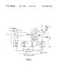
- FIG. 1is a diagram of an overall system architecture in accordance with a preferred embodiment of the present invention.
- FIG. 2is a block diagram of a basic architecture for a wireless access communication unit in accordance with various aspects of the present invention.
- FIG. 3is a diagram of a software architecture for the wireless access communication unit of FIG. 2 .
- FIG. 4is a block diagram of a basic architecture for a base station.
- FIG. 5is a diagram of a software structure for the base station of FIG. 4 .
- FIG. 6is a block diagram illustrating addressing of multiple trunks connected to a wireless access communication unit according to a preferred embodiment of the present invention.
- FIG. 7is a diagram illustrating an interface signaling structure between a base station and a base station controller.
- FIG. 8is an abstract diagram of a system protocol architecture.
- FIG. 9is a diagram illustrating a division of bearer path functions among a wireless access communication unit (CPRU), base station and base station controller components of a preferred communication system.
- CPRUwireless access communication unit
- FIG. 10is a diagram showing interfaces between the different components of a preferred system.
- FIG. 11is a diagram of multiple wireless access communication units in different location areas connected to a single base station controller.
- FIG. 12is a call flow diagram for a network-level registration procedure.
- FIG. 13is a call flow diagram for a network-level de-registration procedure.
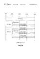
- FIG. 14is a call flow diagram for dial tone, digit transmission and digit analysis for a communication system having a PBX.
- FIG. 15is a call flow diagram for dial tone, digit transmission and digit analysis for a communication system including a key system (KTS).
- KTSkey system
- FIG. 16is a call flow diagram for dial tone, digit transmission and digit analysis for a communication system having another type of PBX.
- FIG. 17is a call flow diagram for dial tone, digit transmission and digit analysis for a communication system having another type of KTS.
- FIG. 18is a call flow diagram for a successful outgoing call setup without PSTN interworking.
- FIG. 19is a call flow diagram for a successful outgoing call setup with PSTN interworking.
- FIG. 20is a call flow diagram for a scenario involving call waiting.
- FIG. 21is a call flow diagram for a scenario involving three-way calling.
- FIG. 22is a call flow diagram for DTMF tone transmission.
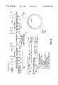
- FIG. 23is a timing diagram of an over-the-air protocol that may be used in the communication system shown in FIG. 1 .
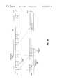
- FIG. 24is a timing diagram of an alternative over-the-air protocol for the communication system shown in FIG. 1 .
- FIG. 1is a diagram showing an overall system architecture of a communication system 101 in accordance with a preferred embodiment of the present invention.
- a plurality of telephone stations 102are connected to a central telephone switch 105 .
- telephone stations 102could comprise telephones, modems, fax machines, or other devices that are capable of communicating over a completed call connection.
- the central telephone switch 105will be referred to herein as a “customer premises equipment” or “CPE.”
- the CPE 105may comprise, for example, a private-branch exchange (PBX) system or a key system.
- PBXprivate-branch exchange
- key systemThe design of various types of PBX and key systems is well known in the art.
- the CPEis connected to both a public switched telephone network (PSTN) 125 and a wireless access communication unit 106 (also referred to occasionally herein, or in the drawings, as a “customer premises radio unit” or “CPRU”).
- PSTNpublic switched telephone network
- CPRUcustomer premises radio unit
- callsare selectively placed over the PSTN 125 and the wireless access communication unit 106 according to the type of call.
- the wireless access communication unit 106communicates over a wireless trunk 108 (which comprises a plurality of wireless communication links) to a base station 109 .
- the base station 109is connected, along with other base stations 109 in adjacent or nearby geographical regions, to a base station controller 112 .
- the base station controller 112is connected to a transcoding unit 115 , which is connected to a mobile switching center (MSC) 116 .
- MSCmobile switching center
- the base station controller 112may be connected directly to the mobile switching center 116 , without the intermediary transcoding unit 115 .
- the mobile switching center 116is connected to the PSTN 125 .
- the base station controller 112is also connected to an operations and maintenance center 120 , which is in turn connected to an operations support system (OSS) 122 .
- the mobile switching center 116is connected to a home location register and authentication center (HLR/AuC) 123 and to the operations support system 122 , as shown in FIG. 1 .
- the base station 109may also be connected to a local management terminal 121 .
- the inventionprovides in one aspect for the transmission of dialed digits (such as DTMF tones) over a communication path that includes at least one wireless link.
- dialed digitsare transmitted from the wireless access communication unit 106 to the base station 109 as signaling messages.
- dialed digitsare transmitted from the wireless access communication unit 106 to the network using GSM DTAP messages to indicate the start and stop of each digit.
- the DTAP messagesare relayed transparently through the base station 109 and base station controller 112 to the mobile switching center 116 . Further details relating to digit transmission are described later herein, after a description of some of the structure and operation of basic components of a preferred system.
- callsmay be placed from telephone stations 102 directly over the PSTN 125 (i.e., over a landline connection), or over the wireless trunk 108 to the PSTN 125 by utilizing the wireless access communication unit 106 .
- a callWhen a call is to be initiated at one of the telephone stations 102 , it may be routed either directly to the PSTN 125 or to the wireless access communication unit 106 .
- the routing of the callmay be either based on manual selection, or accomplished automatically based on the number dialed, as further described herein.
- local telephone callsare routed directly to the PSTN 125 , while long distance telephone calls are routed through the wireless access communication unit 106 .
- the CPE 105may comprise, for example, a PBX or a key-type system.
- the PBXis preferably capable of routing an outgoing call placed from a telephone station 102 to the PSTN 125 or to the wireless access communication unit 106 based on either an access digit or the number dialed by the user.
- the usermay, for example, dial a certain first digit (e.g., an ‘8’) for access to the wireless access communication unit 106 , and a different first digit (e.g., a ‘9’) for direct LEC access to the PSTN 125 .
- a certain first digite.g., an ‘8’
- a different first digite.g., a ‘9’
- the usercould, for example, access the wireless access communication unit 106 to make outgoing long distance telephone calls, or the PSTN 125 for other types of outgoing calls.
- some types of PBXscan be configured to analyze the dialed number, and to route long distance and local calls. Utilizing this ability, the PBX can be configured to route long distance calls through the wireless access communication unit 106 and local or emergency calls through the PSTN 125 .
- the usermay manually select a line (either for the wireless access communication unit 106 or the PSTN 125 ) by depressing a key on the telephone deskset.
- the usercould, for example, select the call processing unit 106 for outgoing long distance calls, and the PSTN 125 for other types of outgoing calls.
- Some key systemscan, like certain PBXs, be configured to analyze the dialed number, and to route a call either to the wireless access communication unit 106 or the PSTN 125 depending on the initial digits of the call and/or the number of digits dialed. In this manner, the key system can, for example, be configured to route long distance calls through the wireless access communication unit 106 , and local or emergency calls through the PSTN 125 .
- the systemmay be configured with less flexibility but a potentially simpler architecture.
- the systemcan be configured such that all incoming calls are routed directly from the PSTN 125 to the CPE 105 , and that all outgoing local calls (whether voice or data), all outgoing long distance data calls, and all TTY calls for persons with disabilities are also routed directly through the PSTN 125 .
- the wireless access communication unit 106would generally provide outgoing long distance voice communication capabilities.
- the CPE 105is connected to the wireless access communication unit 106 across a CPE trunk interface 104 .
- the CPE trunk interface 104comprises a plurality of CPE trunks, each of which may comprise, for example, loop-start trunks or ground-start trunks.
- the design of both loop-start trunks and ground-start trunksis well known in the art.
- both loop-start trunks and ground-start trunkscan be supported by the same local area switching equipment (i.e, the same PBX or KTS).
- the PBXpreferably has certain operating characteristics.
- the PBXIn addition to supporting loop-start trunks or ground-start trunks (or both) on the CPE trunk interface 104 between the PBX and the wireless access communication unit 106 , the PBX also preferably supports DTMF address signaling on the loop-start trunks or ground-start trunks.
- the PBXmay be configured to route calls through either the PSTN 125 or the wireless access communication unit 106 , as described previously, and therefore has the ability to identify which trunks lead to the PSTN 125 and which trunks lead to the wireless access communication unit 106 .
- the PBXpreferably has the ability to specify the order in which the trunk groups are tried when an outgoing call is placed and to re-route outgoing long-distance calls through the PSTN 125 instead of the wireless access communication unit 106 in case of access problems from the wireless access communication unit 106 to the wireless system.
- the KTSpreferably has certain operational characteristics.
- the KTSalso preferably supports DTMF address signaling on the loop-start trunks or ground-start trunks, and has the ability to route calls through either the PSTN 125 or the wireless access communication unit 106 , as described above.
- the KTSmay also be provided with supplementary call support features and a route selection feature (i.e., the ability to identify trunk groups leading to the wireless access communication unit 106 and the PSTN 125 , and to specify on the KTS the order in which the trunk groups should be tried). If a route selection feature is provided, the KTS should have the ability to re-route outgoing long-distance calls through the PSTN 125 instead of the wireless access communication unit 106 , in case there are access problems from the wireless access communication unit 106 to the wireless system.
- a route selection featurei.e., the ability to identify trunk groups leading to the wireless access communication unit 106 and the PSTN 125 , and to specify on the KTS the order in which the trunk groups should be tried. If a route selection feature is provided, the KTS should have the ability to re-route outgoing long-distance calls through the PSTN 125 instead of the wireless access communication unit 106 , in case there are access problems from the wireless access communication unit 106 to the wireless system.
- FIG. 6is a diagram illustrating an embodiment of a wireless access communication unit 605 connected to a CPE 105 (see FIG. 1) across a plurality of CPE trunks 602 (in this example, four CPE trunks 602 ).
- the wireless access communication unit 605also is connected over a plurality of wireless communication links (or “pipes”) 609 to a wireless network and, in particular, to a base station (not shown in FIG. 6 ).
- the wireless access communication unit 605establishes the wireless communication links 609 and correlates therewith the CPE trunks 602 , so that communication for a particular CPE trunk 602 is carried out over an assigned wireless communication link 609 .
- Users connected to the CPE 105can obtain access to the wireless access communication unit 605 (and, hence, to the wireless network) by being connected through the CPE 105 to one of CPE trunks 602 .
- a potentially large number of users connected to the CPE 105can have the ability to complete calls to the wireless network, with the number of users able to make calls simultaneously equaling the number of CPE trunks 602 (and wireless communication links 609 ) available.
- the wireless access communication unit 106acts as the gateway for the CPE 105 to the wireless network, and preferably performs a variety of functions.
- the wireless access communication unit 106performs off-hook detection for outgoing calls and supports provision of a dial tone to the CPE 105 (and thereby to the telephone station 102 initiating the call).
- the wireless access communication unit 106also initiates acquisition of a wireless communication channel (such as an over-the-air time slot, for example, if the wireless network is a TDMA and/or TDD system), and initiates call control procedures.
- a wireless communication channelsuch as an over-the-air time slot, for example, if the wireless network is a TDMA and/or TDD system
- the wireless access communication unit 106detects dialed address digits (i.e., DTMF tones) and passes the received digits via call control signaling to the network. The wireless access communication unit 106 decides whether to launch a normal or emergency call depending upon an end-of-dialing indication received from the base station 109 indicating the type of call (based on digit analysis performed at the base station 109 ). In addition, the wireless access communication unit 106 detects off-hook transitions from the CPE 105 , and initiates call release procedures towards the network in response to an off-hook transition. When a call is completed, the wireless access communication unit 106 provides landline-transparent control of disconnect procedures for clearing initiated by the CPE 105 . As part of this function, the wireless access communication unit 106 implements the release guard times supported by conventional wireline systems.
- dialed address digitsi.e., DTMF tones
- the wireless access communication unit 106decides whether to launch a normal or emergency call depending upon an end-of-dialing indication
- the wireless access communication unit 106also supports the signaling of DTMF digits during an active call. As part of this function, the wireless access communication unit 106 detects DTMF tones from the CPE 105 during an active call and relays the digits to the network via DTAP signaling. Also during a call, the wireless access communication unit 106 may pass call progress tones received from the network transparently over the bearer path to the CPE 105 . Whenever call progress DTAP signaling is received from the network, the wireless access communication unit 106 converts the call progress DTAP signals into call progress tones towards the CPE 105 . The wireless access communication unit 106 may generate reorder tones to the CPE 105 when needed, so as to indicate congestion of the wireless network or permanent signal timer expiry conditions to the CPE 105 .
- the wireless access communication unit 106also preferably performs a number of functions related to bearer processing.
- the wireless access communication unit 106performs vocoding for voice communication.
- vocodingincludes encoding/compression of speech towards the network and decoding/de-compression of speech in the reverse direction (i.e., towards the CPE 105 ).
- the wireless access communication unit 106also preferably performs forward error correction (FEC), encryption and decryption for the bearer voice (with the wireless access communication unit 106 and transcoding unit 115 being peer-to-peer endpoints for ciphering), and echo cancellation functions.
- FECforward error correction
- the wireless access communication unit 106encrypts the bearer data prior to transmission over the air (i.e., over the wireless trunk 108 ), and decrypts bearer data received from the network. Echo cancellation functions are supported by the wireless access communication unit 106 so as to suppress the echo potentially generated towards the wireless network if, for example, a 2-4 wire hybrid structure is present at the interface with the CPE 105 .
- the wireless access communication unit 106in conjunction with the wireless system supports management and security features such as call registration, de-registration, user authentication, ciphering of bearer information, and network management functions.
- the wireless access communication unit 106may also support outgoing emergency (i.e., “911”) calls and end-to-end DTMF signaling during active calls.
- the wireless access communication unit 201comprises a plurality of subscriber ports 203 , which are provided for connecting the CPE 105 (see FIG. 1) to the wireless access communication unit 201 across a trunk interface (e.g., trunk interface 104 shown in FIG. 1 ).
- Each subscriber port 203can support one call connection over the wireless access communication unit 201 , and may comprise, for example, an RJ-11 interface. While four subscriber ports 203 are shown in FIG. 2, it will be understood that the number of subscriber ports 203 may vary depending upon the particular application or environment in which the wireless access communication unit 201 is deployed.
- the wireless access communication unit 201may be configured with only a single subscriber port 203 , or may have any number of subscriber ports 203 limited only by practical considerations such as the number of wireless communication channels generally accessible and available to the wireless communication unit 201 .
- the subscriber ports 203may comprise any suitable interface, with an RJ-11 interface being but one example of such an interface.
- Each subscriber port 203is connected to an individual line interface unit or line card section 205 .
- the wireless access communication unit 201comprises four line card sections 205 , one for each subscriber port 203 .
- the line card section 205provides a physical subscriber line interface from the CPE 105 to the wireless access communication unit 201 , and in addition provides digitizing and data compression functions.
- the line card section 205comprises a subscriber interface 207 which is connected to one of the subscriber ports 203 .
- the subscriber interface 207comprises a subscriber line interface circuit (SLIC) 217 , which provides conventional loop interface functions including battery feed, overload protection. supervision, and 2-4 wire hybrid. Both loop-start and ground-start signaling are preferably supported by the line card section 205 .
- SLICsubscriber line interface circuit
- each line card section 205may be individually configured to interface with a loop-start or ground-start trunk.
- the subscriber interface 207further comprises a standard CODEC or, alternatively, a subscriber line audio processing circuit (SLAC) 215 which carries out analog-to-digital and digital-to-analog conversion between the line card section 205 and the user station (e.g., telephone station 102 shown in FIG. 1) connected to the subscriber port 203 .
- the CODEC or SLAC 215provides a standard ⁇ -law pulse code modulation (PCM) interface.
- PCM⁇ -law pulse code modulation
- the subscriber interface 207also comprises a ring generator 216 for generating a ringback tone.
- a digitized data streamis output from the CODEC or SLAC 215 and provided across signal line(s) 214 to a vocoder 206 , which compresses the digitized data stream into a compressed data signal.
- the vocoder 206comprises a relatively high-speed digital signal processor 211 (operating at, e.g., a rate of twenty million instructions per second or other suitable rate), along with support modules such as a high-speed static random-access memory (SRAM) 212 and an EPROM 213 .
- SRAMstatic random-access memory
- the vocoder 206preferably provides, as part of its decoding function, an interpolation capability for deriving predicted speech patterns, so as to handle situations where, for example, the wireless access communication unit 201 detects data frames that contain errors, or else the data frames contain errors that cannot be corrected by forward error correction (FEC).
- the decoding function of the vocoder 206also preferably provides a mute capability for silencing the output to the CPE 105 when beneficial to do so, such as during control traffic exchanges.
- the vocoder 206outputs a compressed data signal at a rate of, e.g., 8 Kbps, which is sent to a control line card assembly (LCA) 226 located in a control section 220 . Control section 220 thereby receives four compressed data signals, one from each of the line card sections 205 .
- LCAcontrol line card assembly
- Each line card section 205also hosts a subscriber interface module (SIM) 208 .
- SIMsubscriber interface module
- the general functions of the SIM 208are to provide system security and store subscriber-specific information, including such things as subscriber authentication information and subscriber-specific data.
- the SIM functionis duplicated for each CPE trunk supported by the wireless access communication unit 201 , as each CPE trunk may be viewed as a different subscriber by the network. This duplication may be explained with reference to FIG. 6 .
- a plurality of CPE trunks 602are shown connected to the wireless access communication unit 605 (each CPE trunk 602 being connected to a subscriber port 203 shown in the more detailed diagram of FIG. 2 ).
- a separate SIM 606is associated with each of the CPE trunks 602 .
- the wireless access communication unit 605comprises four SIMs 606 .
- the wireless access communication unit 605further comprises a plurality of radio interface units 607 , one for each of CPE trunk 602 , for the purpose of passing data and other information to the wireless transceiver (not shown) which handles the physical wireless communication links 609 .
- each subscriber within the communication systemrequires unique identification and possibly different system parameters.
- each CPE trunkis associated with a unique identifier and, preferably, unique authentication and other system parameters, which are implemented at least in part with the separate SIM 208 used in each line card 205 .
- the SIM 208are used in the wireless access communication unit 201 .
- the functionality of the SIM 208may be implemented as one or more non-removable SIM chips within the wireless access communication unit hardware architecture.
- the SIM 208stores within a non-volatile memory (such as a ROM, or non-volatile RAM) subscriber information such as a subscriber identifier.
- the subscriber identifiercomprises an international mobile subscriber identity (IMSI) number.
- IMSIinternational mobile subscriber identity
- the SIM 208also runs an authentication procedure such as, for example, an “A3” and/or “A8” authentication procedure conventionally used in certain GSM applications. Further details regarding authentication may be found in copending U.S. patent application Ser. No. 08/988,505, previously incorporated herein by reference.
- the control section 220 of the wireless access communication unit 201provides timing and control for virtually all aspects of the wireless access communication unit 201 .
- the control section 220comprises a processor 225 which may comprise, for example, a 16-bit RISC processor (such as a C 165 or C 163 processor manufactured by Siemens Corp.) and associated support modules (i.e., SRAM, flash memory, etc.). Access to the SIM 208 is initiated by the host processor 225 and controlled and formatted by the control line card assembly (LCA) in the control section 220 .
- the processor 225also coordinates most system activities and moves data between the various modules.
- the processor 225is connected to the control LCA 226 which, as noted above, is connected to the vocoder 206 from each of the line card sections 205 .
- the control LCA 226is also connected to a radio interface line card assembly (RIF LCA) 227 .
- the control LCA 226provides the interface between the radio section and the line card section of the wireless access communication unit 201 .
- the control LCA 226packages and formats data, and coordinates and controls the over-the-air (OTA) protocol. It thereby maintains coordination between up to four compressed serial data streams (one from each of the line card sections 205 ) and their respective over-the-air communication channels.
- OTAover-the-air
- the radio interface LCA 227is connected to a baseband processor 228 , which may include a digital radio ASIC (DRA) 229 .
- the baseband processor 228is connected to a radio section 240 .
- the radio section 240preferably comprises a plurality of antennas 243 which are selectable by a selector 242 which is connected to the control LCA 226 . Signals from one or more antennas 243 are thereby provided to a radio transceiver 241 (possibly including multiple radio receivers, one for each antenna 243 ).
- antenna diversity techniquesare utilized such that the wireless access communication unit 201 selects the best antenna (and/or radio receiver) for each frame of time in which it communicates.
- Various antenna selection techniquesare known in the art, or are described in, for example, U.S. patent application Ser. No. 08/826,773 filed Apr. 7, 1997, hereby incorporated by reference as if set forth fully herein.
- the wireless access communication unit 201may be powered either through an external DC power supply 250 or an on-board battery 251 .
- the battery 251may be used as a reserve power supply, being brought into service automatically if the external DC supply 250 is cutoff or otherwise unavailable.
- a power section 221 for the wireless access communication unit 201may comprise local voltage regulators to supply required power to the logic and radio sections, and a switching regulator to supply any requisite loop battery voltage.
- the wireless access communication unit 201may be provided with an LED 231 or other visual display mechanism(s) to indicate the status of the device to an observer.
- the types of status conditions to be displayedmay include, for example, whether the power is on, whether the device is functional (i.e., all self tests have been passed), or whether the device is in service (i.e., is currently registered with a base station).
- compressed serial datais transferred to and from the multiple line cards 205 under the direction of the control LCA 226 .
- the control LCA 226places the compressed serial data in a format suitable for the radio interface LCA 227 . It also performs any desired encryption or adds forward error correction information.
- the control LCA 226transfers the data to the radio interface LCA 227 which passes the data to the baseband processor 228 .
- the radio interface LCA 227keeps track of channel and timing information, and instructs the baseband processor 228 to process the data according to the channel and timing parameters.
- the baseband processor 228comprises a transmitter for formulating continuous phase modulated spread-spectrum signals, or other types of quadrature or related signals, as described, for example, with respect to transmitters shown in U.S. Pat. Nos. 5,629,956, 5,610,940 or 5,548,253, all of which are hereby incorporated herein by reference as if set forth fully herein.
- the baseband processor 228sends the data to the radio section 240 which converts the signal to the appropriate transmission frequency and performs any necessary filtering for transmission over the air.
- the frequency band utilized by the wireless access communication unit 201is generally dictated by the overall communication system within which the unit is deployed. For example, the frequency band may be within the PCS frequency band of 1930 MHz to 1990 MHz, or may be any other suitable frequency band or bands.
- Incoming message signalsare received by one or more of antennas 243 and sent to the radio transceiver 241 for downconversion and/or filtering as needed.
- the downconverted and/or filtered datais then sent to the baseband processor 228 which demodulates the received signal.
- the wireless access communication unit 201transmits and receives messages using a spread spectrum format.
- the baseband processor 228preferably comprises a spread spectrum correlator.
- spread spectrum correlatorsare known in the art, examples of which include embodiments illustrated or described in U.S. Pat. Nos. 5,629,956, 5,610,940, 5,396,515 or 5,499,265, each of which is hereby incorporated by reference as if set forth fully herein.
- the baseband processor 228outputs, among other things, a received signal strength indicator (RSSI), which is used by the control LCA 226 in selecting the best antenna 243 (and/or radio receiver) for reception of the incoming signal.
- RSSIreceived signal strength indicator
- the baseband processor 228provides a stream of data bits to the radio interface LCA 227 , which transfers the data to the appropriate line card 205 based upon the over-the-air communication channel over which the data was received.
- the datais then processed by the line card 205 and sent to the CPE 105 via the particular subscriber port 203 connected to the line card 205 .
- FIG. 3A diagram of a preferred software structure for the wireless access communication unit 201 is shown in FIG. 3 .
- the software of the wireless access communication unit 201is functionally divided into two main components, based on the physical interfaces supported by the wireless access communication unit 201 . These two main components are referred to in FIG. 3 as the line manager 350 and the over-the-air manager 351 .
- the line manager 350generally handles the CPE trunk management and communication between the wireless access communication unit 201 and the CPE 105 . In addition to CPE trunk management and communication interface functions, the line manager 350 is also responsible for call signaling, DTMF recognition, and transfer of collected DTMF digits to the over-the-air manager 351 .
- the line manager 350comprises a plurality of line drivers 303 and a plurality of SIM drivers 304 , one line driver 303 and one SIM driver 304 for each CPE trunk supported by the wireless access communication unit 201 .
- a single line driver 303 and SIM driver 304collectively comprise a CPE line software component 302 .
- the over-the-air manager 351handles the communication interface and link management to the base station 109 (see FIG. 1 ).
- the over-the-air line manager 351is also responsible for receiving DTMF digits from the CPE 105 (via the line manager 350 ) and relaying the DTMF digits to the base station 109 (which ultimately conveys them to the PSTN 125 ), as set forth in more detail hereinafter.
- the over-the-air line manager 351also implements the over-the-air communication protocol, including end-to-end communication with various network entities such as the base station controller 112 and mobile switching center 116 (shown in FIG. 1 ).
- over-the-air communication protocolsthat may be implemented by the over-the-air manager 351 include, for example, the GSM direct application transfer part (DTAP) protocol, or the IS-661 over-the-air (“O-Notes”) protocol as described in the OMNI_Notes_RMT Protocols Rev. 02.03D (release date June 30, 1997), appearing as a Technical Appendix A filed herewith, and hereby incorporated by reference as if set forth fully herein.
- the over-the-air manager 351 of the wireless access communication unit 201preferably implements the IS-661 protocol as set forth in the above-referenced OMNI_Notes_RMT Protocols publication, or a variation thereof.
- the over-the-air manager 351comprises a plurality of CPE line link objects 310 , one for each CPE trunk (i.e., subscriber port 203 ) supported by the wireless access communication unit 201 .
- Each CPE line link object 310provides the signaling resource for a single CPE line or trunk, and comprises several components which together form a signaling protocol stack.
- the components of the signaling protocol stackwork together to interface with a CPE line to provide call management, mobility management and radio resource functionality required to complete a voice call, and the registration functionality required to utilize network resources.
- Each CPE line link object 310comprises a CPE line manager 311 , the purpose of which is to interface with the CPE line software component 302 for the appropriate CPE line or trunk.
- the CPE line managerinterfaces with a GSM call management component 312 and a GSM call registration component 313 , both of which interface with a GSM mobility management component 314 .
- the GSM mobility management component 314interfaces with a protocol adaption (PAL) component 315 , which interfaces with an over-the-air state (OTA) machine 316 .
- PALprotocol adaption
- OTAover-the-air state
- the OTA state machine 316is generally responsible for managing the physical radio interface, and communicates with the radio transmit/receiver interface and slot management (RTRX) component 321 .
- the CPE line manager 311signals the GSM mobility management component 314 to initiate connection establishment procedures, as described in more detail hereinafter with respect to the call flow diagrams appearing in FIGS. 13 through 22.
- the CPE line manager 311also controls transmission of DTMF digits to the network, the enabling of the speech path, generation of ringback tones, generation of a busy tone (in non-PSTN interworking situations), and passing of on-hook indication to the CPE 105 .
- the CPE line manager 311manages CPE-initiated call clearing as well as normal and emergency call procedures.
- the GSM call management component 312 , GSM registration component 313 , and GSM mobility management component 314provide a degree of GSM functionality relating to call management, registration, and mobility management, respectively.
- the protocol adaption component 315adapts, if necessary, the GSM signaling protocol to the over-the-air protocol (such as, for example, to the IS-661 over-the-air protocol).
- the OTA state machine 316implements the over-the-air protocol and, as noted, manages the physical radio interface.
- the OTA manager 351further comprises a hardware services component 320 which provides a programming interface to the hardware (including hardware controlled by the line drivers 303 and SIM drivers 304 ) of the wireless access communication unit 201 .
- the OTA manager 351may comprise a realtime operating system (RTOS) 330 , which may be a multi-tasking operating system, as well as a power-on/reset initialization (POST) component 323 and a debug port manager 322 .
- RTOSrealtime operating system
- POSTpower-on/reset initialization
- the debug port manager 322if provided, allows access externally to the internal status of the software, and also permits software downloads.
- the OTA manager 351also comprises an operations, administration and management (OAM) component 324 .
- the OAM componentruns at the application level, and performs such functions as recognition of faults, creating and sending alarms, and communicating with the line manager 350 for call processing data needed in fault detection and alarms.
- the types of faults or failures monitoredmay include, for example, hardware failures (such as power supply failures, radio unit failures, line card failures, and so on), software failures, communication failures, and quality of service failures (e.g., unsuccessful call attempts per time period, time slot interchange requests per time period, unsuccessful time slot interchanges per time period, number of dropped calls per time period, channel quality as indicated by bit error rate, and so on), among others.
- Fault reportingmay be coordinated such that a single fault that causes multiple failures due to the dependency of the software, hardware and telecom functions will result in a single fault being reported.
- the functionality of the over-the-air manager 351 used to support the wireless access communication unit 201may be viewed as a subset or modification of the functionality that would be used to support a mobile user application.
- the mobility management interface (MMI) software component used in a conventional GSM system to support a mobile useris, in the software architecture shown in FIG. 3, replaced with a CPE line manager 311 .
- a logical instance of the signaling protocol stackis provided for each CPE line connected to the wireless access communication unit 201 (as opposed to having a single logical instance of the signaling protocol stack for a mobile user application), and the SIM driver is modified over a mobile user application to accommodate multiple SIMs (or their logical equivalents) by, for example, the provision of multiple independent STM drivers 304 .
- an abilityis added to associate a hardware voice path from the CPE 105 with a base station communication link.
- the signaling protocolmay also be modified, as further described herein, to support digit analysis by the base station 109 (see FIG. 1 ). DSAT and DTA adaptor software components conventionally used in certain mobile user applications are not needed by the wireless access communication unit 201 , and are therefore not implemented.
- a base station 109interfaces with the wireless access communication unit 106 to allow access to the PSTN 125 .
- a block diagram of a preferred base station 401is shown in FIG. 4 .
- the base station 401comprises a number of separate components connected together by a common global bus backplane, as illustrated in FIG. 4 . These components include a digital line card 404 , an over-the-air (OTA) processor card 405 , a power supply module 407 , and a plurality of radio cards 406 , all of which reside on an electronics module 420 .
- the electronics module 420is connected to an I/O module 421 , which comprises protection circuitry 403 to prevent such things as damage from short circuits.
- Each radio card 406is connected, via the protection circuitry 403 , to one of a plurality of antennas 403 .
- the digital line card 404is connected, via protection circuitry 403 , to the PSTN 125 (through base station controller 112 and MSC 116 , as shown in FIG. 1) over a backhaul line 430 , and possibly to other base stations 109 as well over other physical connections.
- the base station 401may be connected to a local AC power supply line 425 , if available.
- the wireless access communication unit(identified by reference numeral 412 in FIG. 4) transmits over-the-air messages to and receives over-the-air messages from the base station 401 .
- the multiple antennas 411 and radio cards 406are used at the base station 401 for achieving antenna diversity. Typically one antenna 411 is selected at a given time for transmitting or receiving over-the-air signals.
- the OTA processor card 405may comprise a spread spectrum correlator and other baseband processing circuitry for correlating a spread spectrum signal received from the wireless access communication unit 412 and converting it to data bits.
- the OTA processor card 405transfers data to the digital line card 404 , which formats the data and sends it over a backhaul line 430 to the PSTN 125 via the other intervening system components (such as the base station controller 112 and MSC 116 ). Similarly, the digital line card 404 receives data from the PSTN 125 , and transfers the data to the OTA processor card 405 which formats the data for the over-the-air protocol and transmits the formatted data using a selected radio card 406 and antenna 411 .
- the primary functions of the radio cards 406are to transmit and receive RF data packs, to perform packet data integrity services (e.g., cyclic redundancy checks), and to support diversity algorithms.
- the primary function of the OTS processor card 405is to move bearer data between the radio cards 406 and the digital line card 404 .
- the OTA processor card 405also executes operations, administration, management and provisioning (OAM&P) requests from the digital line card 404 , communicates signaling information (using internal base station messages or “I-Notes”) with the digital line card 404 , and communicates signaling information (using over-the-air signaling messages or “O-Notes”) with the wireless access communication unit 412 .
- OAM&Poperations, administration, management and provisioning
- the primary functions of the digital line card 404are to handle link access procedures for the “D-channel” (LAPD) transport on the backhaul line 430 , to exchange bearer data between the OTA processor card 405 and the network-side backhaul components (such as the base station controller 112 ), and to multiplex and demultiplex bearer data on the backhaul line 430 .
- LAPD“D-channel”
- the digital line card 404include synchronizing the over-the-air bearer frame timing with the timing on the backhaul line 430 (such as a T 1 line), to provide translation between the OAM&P procedures supported on the network and radio interfaces, to map internal base station messages (e.g., I-Notes) to/from the LAPD transport on the backhaul, and to communicate signaling information (using, e.g., signaling I-Notes) with the OTA processor card 405 .
- I-Notesinternal base station messages
- signaling informationusing, e.g., signaling I-Notes
- FIG. 5A preferred high level software architecture for the base station 401 is depicted in FIG. 5 .
- the software of the base station 401is split into two functional groups, one functional group relating to the over-the-air functions and the other functional group relating to the line card functions. These two main functional groups are shown in FIG. 5 as the OTA manager 502 and the line card manager 503 , each of which preferably runs on its own processor board. Further details regarding the software architecture for the base station 401 may be found in the copending patent applications previously incorporated herein by reference.
- FIG. 5Various interfaces associated with the base station 401 are shown diagrammatically in FIG. 5 as dotted lines, and include an over-the-air interface or “O-interface” 560 between the wireless access communication unit 412 and the base station 401 , an internal interface or “I-interface” 561 between the OTA manager 502 and the line card manager 503 , and a network interface or “N-interface” 562 between the base station 401 and the network-side backhaul components (such as the base station controller 112 , MSC 116 , and PSTN 125 shown in FIG. 1 ). Further information regarding these interfaces may be found in copending U.S. patent Application Ser. No. 08/532,466, previously incorporated herein by reference, or in copending U.S. patent application Ser. Nos. 08/988,482 and 08/988,546, previously incorporated herein by reference. These interfaces are also shown at an abstract level in FIG. 10, described later herein.
- the base station 401manages the radio resources for the wireless access communication unit 412 , and thereby provides support for the network side of the wireless trunk 108 (see FIG. 1 ).
- a wide variety of different communication schemes and radio resource protocolsmay be used. If, for example, the base station 401 implements an IS-661 protocol for over-the-air communication, then the base station 401 manages the resources necessary to support the wireless communication channels between the wireless access communication unit 412 and the base station 401 , including time slots and spread spectrum codes.
- the base station 401also provides multiplexing functions for the transfer of data to and from the backhaul line 430 providing the connection to the PSTN 125 .
- the base station 401may, for example, multiplex data over a T 1 (or fractional T 1 ) backhaul line 430 to the base station controller 112 , which, as noted, pipes the data to and from the PSTN 125 via the MSC 116 .
- Protocol signaling over the N-Interface 562which connects the base station 401 (or 109 in FIG. 1) to the base station controller 112 (see FIG. 1 ), may be transported using the Q9.21 LAPD protocol.
- Protocol signaling over the O-Interface 560which connects the base station 401 to the wireless access communication unit 412 , may be accomplished using over-the-air signaling messages (“O-Notes”) according to the IS-661 protocol.
- the O-Notesmay be transmitted along with bearer data in IS-661 RF packets.
- the base station 401connects and manages radio and terrestrial bearer channels for call-related features, and supports system administration via OAM&P controlled by the system operator through the operations management center 120 (see FIG. 1 ). As part of its radio resource management functionality, the base station 401 supports outgoing voice calls (normal and emergency) from the wireless access communication unit 412 . Incoming pages to the wireless access communication unit 412 may optionally be supported by the base station 401 .
- the base station 401manages mapping of the radio channels (including the wireless communication channels of the wireless trunk 108 ) to the terrestrial (i.e., backhaul) channels.
- the base station 401also provides, through its OAM&P functionality, support for administrative state changes, configuration, provisioning of the radio resources, fault management and alarm management for the radio resources.
- the base station 401manages and allocates the backhaul channels (such as T 1 time slots) over the backhaul line 430 .
- the base station 401indicates backhaul channel allocation to the base station controller 112 through signaling messages.
- the base station 401is involved in establishing, maintaining and tearing down outgoing voice calls received from the wireless access communication unit 412 .
- Preferred call flows pertaining to such functionsare shown in, e.g., FIGS. 14 through 19, and described in more detail hereinafter.
- the base station 401also relays DTMF signaling from the end user to the PSTN 125 , if necessary, during an active telephone call. This signaling is relayed transparently through the base station 401 , and is supported by the I-interface and N-interface transport procedures.
- the base station 401also provides digit analysis for outgoing telephone calls.
- the base station 109is connected to the base station controller 112 over an interface such as an N-interface (such as the N-interface 562 described previously with respect to FIG. 5 ).
- Data(including signaling messages and bearer traffic) are passed between the base station 109 and the base station controller 112 across the N-interface.
- a preferred base station controller 112may be viewed in one aspect as a base station subsystem controller that is used for managing one or more base stations 109 .
- a primary responsibility of the base station controller 112is to provide an interface between the MSC 116 and the radio access subsystem (i.e., the system components responsible for establishing and maintaining the physical radio channels).
- the base station controller 112incorporates aspects of the IS-661 communication protocol and the GSM communication protocol, thereby using what may be referred to as a “hybrid” protocol. Details of a preferred communication protocol may be found in, for example, copending U.S. patent application Ser. Nos. 08/988,482 and 08/988,546 both previously incorporated herein by reference. In an alternative embodiments, the base station controller 112 may be implemented using the IS-661 protocol in its entirety, or the GSM communication protocol in its entirety.
- Call control messages and proceduresrun end-to-end between the wireless access communication unit 106 and the MSC 116 , and are relayed transparently through the base station controller 112 .
- the base station controller 112provides a signaling path between the wireless access communication unit 106 and the MSC 116 to carry out call control signaling.
- the base station controller 112transmits and receives information to the transcoding unit 115 , shown in FIG. 1 .
- the transcoding unit 115in one aspect comprises a base station subsystem (BSS) entity located, in one embodiment, between the base station controller 112 and the MSC 116 .
- BSSbase station subsystem
- the transcoding unit 115is under management control of the base station controller 112 , but is physically located on the premises of the MSC 116 , thereby allowing the base station controller 112 to be remotely located from the site of the MSC 116 .
- the transcoding unit 115comprises a number of transcoding unit shelves, operating independently of one another but under the control of the base station controller 112 .
- each transcoding unit shelfsupports up to 92 bearer channels.
- the transcoding unit 115generally provides the network side processing of key functions on the bearer path. This processing may include, for example, speech transcoding, network-side forward error correction (FEC), and network-side enciphering and deciphering of bearer voice.
- FECforward error correction
- FIG. 9is a high level diagram illustrating a preferred breakdown of bearer path functions performed at the wireless access communication unit 106 , the base station 109 , and the base station controller and/or transcoding unit 115 .
- the wireless access communication unit bearer path functions 901include voice encoding and decoding. 911 forward error correction (FEC), 912 encryption and decryption, 913 and tone generation 914 .
- FECforward error correction
- the speech encoding/decoding, encryption/decryption and FEC functions performed in the wireless access communication unit 106are mirrored in the based station controller 112 and/or transcoding unit 115 .
- the transcoding unit 115is connected to the mobile switching center (MSC) 116 , which is connected to the PSTN 125 .
- the MSC 116is a cellular switch that acts as an interface between the base station subsystem (BSS) and the PSTN 125 , and acts as the gateway to the long-distance network.
- the MSC 116has telephone exchange capabilities including call setup, routing selection, switching between incoming and outgoing channels, control of communications, and release of connections.
- the MSC 116performs its functions while taking into account mobility management aspects of the subscriber, including authentication, ciphering, radio resource management, and location register updating procedures.
- the MSC 116also allows the wireless access communication unit 106 interworking to the PSTN 125 .
- the 116may be part of a digital multiplex system (DMS) “super-node” based switching system, capable of providing the switching functions in a cellular network.
- DMSdigital multiplex system
- VLRvisitor location register
- the wireless access communication unit 106For “outgoing” voice call establishment initiated by the CPE 105 , the wireless access communication unit 106 handles acquisition of an over-the-air communication channel, mobility management connectivity, and call setup, and in addition is preferably capable of handling various error or exception conditions.
- the wireless access communication unit 106detects a trunk seizure by the CPE 105 , the wireless access communication unit 106 marks the CPE trunk as “busy” and issues a dial tone (assuming that it is able to communicate with a base station 109 ).
- the wireless access communication unitinitiates an over-the-air communication channel acquisition procedure.
- the dial toneis removed when the wireless access communication unit 106 detects the first dialed digit from the CPE 105 , or if it detects an on-hook from the CPE 105 prior to receiving any digits therefrom.
- the wireless access communication unit 106On receiving a trigger from the CPE 105 to set up an outgoing call or perform a registration, the wireless access communication unit 106 attempts to acquire an over-the-air communication channel.
- the acquisition of an over-the-air communication channelis accomplished by interacting with a control channel of the wireless system.
- the channel acquisition processmay entail acquiring a time slot in a time frame established by the base station 109 . Acquisition of a time slot may be carried out, for example, according to a handshake protocol described in more detail in U.S. Pat. No. 5,455,822, assigned to the assignee of the present invention, and hereby incorporated by reference as if set forth fully herein.
- the wireless access communication unit 106proceeds with digit transmission and analysis. On detecting the first dialed digit, the wireless access communication unit 106 removes the dial tone and initiates a digit analysis procedure. In a preferred embodiment, digits are relayed from the wireless access communication unit 106 as they are received after the over-the-air communication channel has been established, and digit analysis is performed at the base station 109 . The base station 109 stores the digits and analyzes them, determining the type of call and the end of the dialing sequence. Examples of techniques for digit analysis by a base station are further described in copending U.S. patent application Ser. No. 08/676,975 filed Jun. 8, 1996, hereby incorporated by reference as if set forth fully herein.
- the base station 109analyzes the digits as follows. If the base station 109 detects the digit pattern “X11,” where “X” is a “4” or a “9”, it will consider dialing to be complete. If the digit sequence is “911,” the base station 109 marks the call type as an emergency call. Any other type of call is marked as a normal call. If the first three digits are not “411” or “911,” then the base station 109 continues to receive digits, and uses a dialing-complete timeout period (of, e.g., four seconds) to detect the end of dialing.
- a dialing-complete timeout periodof, e.g., four seconds
- a dialing timeris activated when the first digit is received by the base station 109 , and is reset each time a new digit is received.
- the dialing timerexpires, the base station 109 considers dialing to be complete.
- the base station 109On determining that the dialing sequence is complete, the base station 109 issues a trigger to the wireless access communication unit 106 to continue with call establishment, including mobility management connection establishment and call setup. This trigger also indicates the type of call (i.e., normal versus emergency).
- the wireless access communication unit 106may not generate a dial tone. Instead, it will issue a reorder tone to the user via the CPE 105 . If no digit is received by the wireless access communication unit for a predetermined timeout period (e.g., 16 seconds) after the trunk seizure is recognized by the wireless access communication unit 106 , then it applies permanent signal treatment on the trunk (i.e., treats it as an extended off-hook situation), as further described below.
- a predetermined timeout periode.g. 16 seconds
- the MSC 116takes appropriate action. In such situations, the base station 109 generally detects end-of-dialing and triggers the wireless access communication unit 106 to set up the call. The incomplete or invalid digit sequence is then filled into a DTAP Setup message by the base station 109 and sent to the MSC 116 . The digit analysis performed at the MSC 116 detects the exception condition, causing the MSC 116 to return a DTAP Release Complete message to the wireless access communication unit 106 , indicating that the dialed number is invalid.
- the wireless access communication unit 106provides the capability to establish, maintain and tear down normal outgoing voice calls through a GSM-based segment that provides connectivity to the long distance functionality of the PSTN 125 .
- the wireless access communication unit 106 and other system componentsprovide wireline transparency to a CPE 105 by supporting standard signaling functions on the CPE interface, including trunk supervisory signaling, address signaling, and provision of call progress tones to the CPE 105 .
- the wireless access communication unit 106registers with a nearby base station 109 and also with the PSTN 125 .
- registrationmay generally be described as the process by which a subscriber (i.e., a CPE trunk 602 ) connected to the wireless access communication unit 106 identifies itself to the network. Since each CPE trunk connected to the wireless access communication unit 106 is looked upon by the network as an individual subscriber, the registration procedure is typically carried out on behalf of an individual CPE trunk, and may need to be repeated for multiple CPE trunks.
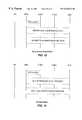
- FIG. 12is a call flow diagram illustrating a network-level registration procedure.
- the wireless access communication unit 106acquires a wireless communication channel (e.g., a time slot in a TDMA or TDD system, or a frequency channel in an FDD system, or other defined channel) to a nearby base station 109 .
- the wireless communication channelis acquired according to the particular protocol utilized by the wireless system.
- the wireless access communication unit 106then performs a network-level registration procedure, according to the particular registration protocol utilized by the system.
- the registration proceduremay involve, for example, a location updating procedure on the A-interface.
- the wireless access communication unit 106performs network-level registration at regular intervals thereafter, with periodicity controlled by the network infrastructure.
- the wireless access communication unit 106may also perform network-level registration if it starts communicating through a base station 109 in a different location area from the base station with which it had been previously communicating. After registration, the wireless communication channel is surrendered, and the MSC 116 initiates a resource release procedure, as illustrated in FIG. 12 .
- the wireless access communication unit 106may also perform periodic registration with the base station 109 at regular intervals, with a periodicity controlled by the base station 109 and/or configurable through OAM&P. For each registration attempt, the wireless access communication unit 106 acquires a wireless communication channel, registers, and then surrenders the wireless communication channel, unless a call is in progress. If a call is in progress, the wireless communication unit 106 need not acquire a new channel, but can, if possible under the particular wireless protocol, send registration information over the existing communication channel. In addition to periodic base-level registration, the wireless access communication unit 106 also performs initial registration with a base station 109 when it starts communicating through a base station different from but in the same location area as a base station with which it was previously communicating.
- FIG. 13is a call flow diagram illustrating a network level de-registration procedure.
- the wireless access communication unit 106acquires a wireless communication channel (e.g., a TDMA time slot) to a nearby base station 109 .
- the wireless communication channelis acquired according to the particular RF protocol utilized by the wireless system.
- the wireless access communication unit 106then performs a network-level de-registration procedure, such as an IMSI detach procedure, according to the particular protocol utilized by the system.
- the wireless communication channelis surrendered, and the MSC 116 initiates a resource release procedure, as illustrated in FIG. 13 .
- FIGS. 14 through 19are call flow diagrams illustrating dial tone, digit transmission, digit analysis and call setup for outgoing calls under various types of CPE embodiments, including PBXs and KTSs with different levels of routing intelligence.
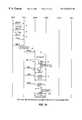
- FIG. 14, for example,is a call flow diagram illustrating dial tone, digit transmission and digit analysis for a CPE 105 embodied as a “dumb” PBX—i.e., a PBX without the ability to route calls based on analysis of the dialed number. As shown in FIG.
- the user 102e.g., a telephone station, as shown in FIG. 1 goes off-hook, sending an off-hook stimulus to the CPE 105 (i.e., the PBX).
- the PBX 105Upon detecting the off-hook signal, the PBX 105 issues a dial tone to the user 102 .
- the user 102dials an access code (i.e., a predetermined digit, such as ‘8’) to access the wireless trunk offered by the wireless access communication unit 106 .
- an access codei.e., a predetermined digit, such as ‘8’
- the PBX 105removes the dial tone and seizes a trunk connected to the wireless access communication unit 106 .
- the wireless access communication unit 106On detecting seizure of a trunk, the wireless access communication unit 106 issues a secondary dial tone to the user 102 .
- the secondary dial toneis delivered via the PBX 105 to the user 102 .
- the wireless access communication unit 106commences acquisition of an over-the-air communication channel. In a TDMA or TDD system, for example, this step in the procedure generally entails seizing an over-the-air time slot.
- the user 102Upon detecting the dial tone, the user 102 starts dialing the digits of the party to be called.
- the wireless access communication unit 106detects the first digit, after which it removes the secondary dial tone. If acquisition of the over-the-air communication channel has not been completed by this time, the wireless access communication unit 106 stores the received digits in a temporary buffer.
- the wireless access communication unit 106After it successfully acquires an over-the-air communication channel, as shown in FIG. 14, the wireless access communication unit 106 sends a control traffic service request (CT-SRQ) message to the base station 109 requesting service from the digit analysis application in the base station 109 .
- the base station 109commences the digit analysis application, and returns a control traffic acknowledgment (CT-ACK) message to the wireless access communication unit 106 .
- the wireless access communication unit 106then transmits the digits received from the user 102 to the base station 109 one-by-one as they are received from the user 102 . Each digit is sent as part of a control traffic transport (CT-TRA) message.
- CT-TRAcontrol traffic transport
- each digitmay be indicated by a field of, e.g., four bits in the CT-TRA message.
- the base station 109stores each received digit. After all address digits have been received at the base station 109 , the base station 109 detects that the dialing sequence is complete (according to its digit analysis), and returns a control traffic transport (CT-TRA) message to the central call processing unit 106 , with a message content indicating that dialing is complete. The wireless access communication unit 106 is then able to proceed with the launching of the call.
- CT-TRAcontrol traffic transport
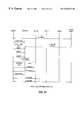
- FIG. 15is similar to FIG. 14, but illustrates dial tone, digit transmission and digit analysis for a CPE 105 embodied as a “dumb” KTS—i.e., a key type system without the ability to route calls based on analysis of the dialed number.
- the user 102first selects an outgoing line to the wireless access communication unit 106 .
- the user 102then goes off-hook, sending an off-hook stimulus to the CPE 105 (i.e., the KTS).
- the CPE 105seizes a trunk connected to the wireless access communication unit 106 .
- the wireless access communication unit 106detects the trunk seizure, and in response issues a dial tone to the user 102 .
- the wireless access communication unitproceeds to acquire an over-the-air communication channel. In a TDMA or TDD system, this step generally entails seizing an over-the-air time slot.
- the wireless access communication unit 106When the user 102 detects the dial tone, the user 102 starts dialing the digits of the party to be called. After detecting the first digit, the wireless access communication unit 106 removes the dial tone. If acquisition of the over-the-air communication channel has not been completed by this time, the wireless access communication unit 106 stores the digits in a temporary buffer.
- the wireless access communication unit 106When it successfully acquires an over-the-air communication channel, the wireless access communication unit 106 sends a control traffic service request (CT-SRQ) message to the base station 109 , as shown in FIG. 15, requesting service from the digit analysis application in the base station 109 .
- the base station 109commences the digit analysis application, and returns a control traffic acknowledgment (CT-ACK) message to the wireless access communication unit 106 .
- the wireless access communication unit 106then transmits the digits received from the user 102 to the base station 109 one-by-one as they are received from the user 102 . Each digit is sent as part of a control traffic transport (CT-TRA) message, as described with respect to FIG. 14 .
- CT-TRAcontrol traffic transport
- the base station 109After all address digits have been received at the base station 109 , the base station 109 detects that the dialing sequence is complete (according to its digit analysis), and returns a control traffic transport (CT-TRA) message to the central call processing unit 106 , with a message content indicating that dialing is complete. The wireless access communication unit 106 is then able to proceed with the launching of the call.
- CT-TRAcontrol traffic transport
- FIG. 16in a fashion similar to FIGS. 14 and 16, illustrates dial tone, digit transmission and digit analysis, but for a CPE 105 embodied as a PBX system which has sufficient built-in intelligence to route calls based on analysis of the dialed number.
- the user 102first goes off-hook, sending an off-hook stimulus to the CPE 105 (i.e., the PBX).
- the CPE 105Upon detecting the off-hook signal, the CPE 105 issues a dial tone to the user 102 .
- the user 102dials an access code (i.e., a predetermined digit, such as ‘8’ or ‘9’) to access an outside line.
- an access codei.e., a predetermined digit, such as ‘8’ or ‘9’
- the CPE 105Upon detecting the access code digit, the CPE 105 removes the dial tone and starts digit analysis. On detecting that the dialed number is the predetermined digit of the access code, the CPE 105 issues a secondary dial tone to the user 102 .
- the user 102then starts dialing the digits of the party to be called.
- the CPE 105removes the dial tone and starts digit analysis.
- the CPE 105determines from its digit analysis that a complete telephone number has been dialed.
- the CPE 105also determines from its digit analysis whether or not the call is long distance (e.g., the first digit of the call to be placed following the access code is a ‘1’), and if the call is long distance seizes a trunk connected to the wireless access communication unit 106 . If the call is not long distance, the CPE 105 routes the call directly to the PSTN 125 .
- the wireless access communication unit 106Upon detecting seizure of a CPE trunk, the wireless access communication unit 106 issues a secondary dial tone to the user 102 .
- This secondary dial toneis muted by the CPE 105 on the user side—i.e., it is not passed along to the user 102 .
- the wireless access communication unit 106proceeds to acquire an over-the-air communication channel. In a TDMA or TDD system, for example, this step generally entails seizing an over-the-air time slot.
- the secondary dial toneis detected by the CPE 105 , the CPE 105 begins to outpulse to the wireless access communication unit 106 the digits earlier received from the user 102 as DTMF tones.
- the wireless access communication unit 106Upon detecting the first digit (i.e., DTMF tone), the wireless access communication unit 106 removes the secondary dial tone. If acquisition of the over-the-air communication channel has not been completed by this time, the wireless access communication unit 106 stores the digits in a temporary buffer until such time as a wireless communication channel is obtained.
- the first digiti.e., DTMF tone
- the wireless access communication unit 106After it successfully acquires an over-the-air communication channel, the wireless access communication unit 106 sends a control traffic service request (CT-SRQ) message to the base station 109 requesting service from the digit analysis application in the base station 109 .
- the base station 109commences the digit analysis application, and returns a control traffic acknowledgment (CT-ACK) message to the wireless access communication unit 106 .
- the wireless access communication unit 106then transmits the digits received from the user 102 to the base station 109 one-by-one as they are received from the user 102 . Each digit is sent as part of a control traffic transport (CT-TRA) message.
- CT-TRAcontrol traffic transport
- the base station 109After all address digits have been received at the base station 109 , the base station 109 detects that the dialing sequence is complete, and returns a control traffic transport (CT-TRA) message to the central call processing unit 106 , with a message content indicating that dialing is complete. The wireless access communication unit 106 is then able to proceed with the launching of the call.
- CT-TRAcontrol traffic transport
- FIG. 17is similar to FIGS. 14, 15 and 16 , but illustrates dial tone, digit transmission and digit analysis for a CPE 105 embodied as a key type system (KTS) which has sufficient built-in intelligence to route calls based on analysis of the dialed number.
- KTSkey type system
- the user 102first goes off-hook, sending an off-hook stimulus to the CPE 105 (i.e., the KTS).
- the CPE 105Upon detecting the off-hook signal, the CPE 105 issues a dial tone to the user 102 .
- the user 102then starts dialing the digits of the party to be called.
- the CPE 105removes the dial tone and starts digit analysis.
- the CPE 105determines from its digit analysis that a complete telephone number has been dialed. The CPE 105 also determines from its digit analysis whether or not the call is long distance (e.g., the first digit dialed is a ‘1’), and if the call is long distance seizes a trunk connected to the wireless access communication unit 106 . If the call is not long distance, the CPE 105 routes the call directly to the PSTN 125 .
- the wireless access communication unit 106When a trunk is seized, the wireless access communication unit 106 issues a secondary dial tone to the CPE 105 .
- This secondary dial toneis muted by the CPE 105 on the user side—i.e., it is not passed to the user 102 .
- the wireless access communication unit 106proceeds to acquire an over-the-air communication channel. In a TDMA or TDD system, this step generally entails seizing an over-the-air time slot.
- the secondary dial toneis detected by the CPE 105 , the CPE 105 begins to outpulse the digits earlier received from the user 102 to the wireless access communication unit 106 .
- the wireless access communication unit 106Upon detecting the first digit, the wireless access communication unit 106 removes the secondary dial tone. If acquisition of the over-the-air communication channel has not been completed by this time, the wireless access communication unit 106 stores the digits in a temporary buffer.
- the wireless access communication unit 106After it successfully acquires an over-the-air communication channel, the wireless access communication unit 106 sends a control traffic service request (CT-SRQ) message to the base station 109 requesting service from the digit analysis application in the base station 109 .
- the base station 109commences the digit analysis application, and returns a control traffic acknowledgment (CT-ACK) message to the wireless access communication unit 106 .
- the wireless access communication unit 106then transmits the digits received from the user 102 to the base station 109 one-by-one as they are received from the user 102 . Each digit is sent as part of a control traffic transport (CT-TRA) message.
- CT-TRAcontrol traffic transport
- the base station 109After all address digits have been received at the base station 109 , the base station 109 detects that the dialing sequence is complete, and returns a control traffic transport (CT-TRA) message to the central call processing unit 106 , with a message content indicating that dialing is complete. The wireless access communication unit 106 is then able to proceed with the launching of the call.
- CT-TRAcontrol traffic transport
- the wireless access communication unit 106issues a dial tone (or a secondary dial tone) and does not receive digits from the CPE 105 within a preset amount of time, a dial timeout condition will occur. In such a case, the wireless access communication unit 106 releases any over-the-air communication channel that it may have seized and issues permanent treatment to the user (i.e., preforms a de-registration procedure, if necessary, and causes the MSC 116 to release any resources allocated for the call).
- a dial toneor a secondary dial tone
- FIGS. 18 and 19are call flow diagrams illustrating successful call setup procedures in two scenarios.
- FIG. 18illustrates a call flow for a successful CPE-originated normal (i.e., non-emergency) call setup sequence, with non-PSTN interworking at the MSC 116 .
- provision of the dial tone, transmission of digits and digit analysisis carried out according to any of the scenarios illustrated in the call flow diagrams of FIGS. 14 through 17.
- the call flowterminates with an end of dialing indication from the base station 109 to the wireless access communication unit 106 .
- the wireless access communication unit 106Upon receiving the end of dialing indication from the base station 109 , the wireless access communication unit 106 initiates a mobility management connection establishment procedure for a normal call.
- This procedureresults in an SCCP link being established for the call across the A-interface (assuming a GSM system), and further results in a mobility management connection being set up with the MSC 116 for handling the call.
- Part of this proceduremay, if desired, entail authentication and cipher mode setting procedures for the call.
- the wireless access communication unit 106sends a direct transfer application part (DTAP) Setup message to the base station 109 , as illustrated in FIG. 18 .
- the DTAP Setup messagecontains an empty called party address field, and is directed towards the MSC 116 .
- the base station 109intercepts the DTAP Setup message and fills in the called address field with the digits received from the wireless access communication unit earlier during the digit analysis step.
- the base station 109then forwards the DTAP Setup message, via the base station controller 112 , to the MSC 116 .
- the MSC 116acknowledges the receipt of the DTAP Setup message by sending a DTAP Call Proceeding message to the wireless access communication unit 106 , as illustrated in FIG. 18 .
- a bearer resource assignment procedureis then executed on each interface of the wireless fixed-access system, starting from the A-interface 571 and progressing to the O-interface 560 .
- the bearer resource assignment procedureresults in bearer channels being assigned on the A-interface 571 , N-interface 562 and O-interface 560 , and a switched connection being set up through the base station controller 112 .
- the MSC 116sends a DTAP Alerting message to the wireless access communication unit 106 .
- the wireless access communication unit 106provides a ringback tone to the user 102 , via the inband path through the CPE 105 (i.e., the PBX or KTS, or other similar system).
- the MSC 116sends a DTAP Connect message to the wireless access communication unit 106 .
- the wireless access communication unit 106attaches its speech path and removes the ringback tone to the user 102 .
- the wireless access communication unit 106responds to the MSC 116 with a DTAP Connect Acknowledgment message, and the call is then in a conversation state.
- provision of the dial tone, transmission of digits and digit analysisis carried out according to any of the scenarios illustrated in the call flow diagrams of FIGS. 14 through 17.
- the wireless access communication unit 106Upon receiving an end of dialing indication from the base station 109 , the wireless access communication unit 106 initiates a mobility management connection establishment procedure for a normal call. Similar to the call flow of FIG. 18, this procedure results in an SCCP link being established for the call across the A-interface (assuming a GSM system), and further results in a mobility management connection being set up with the MSC 116 for handling the call. Part of this procedure may, if desired, entail authentication and cipher mode setting procedures for the call.
- the wireless access communication unit 106sends a DTAP Setup message to the base station 109 .
- the DTAP Setup messagecontains an empty called party address field, and is directed towards the MSC 116 .
- the base station 109intercepts the DTAP Setup message ancf fills in the called address field with the digits received from the wireless access communication unit earlier during the digit analysis step.
- the base station 109then forwards the DTAP Setup message, via the base station controller 112 , to the MSC 116 .
- the MSC 116acknowledges the receipt of the DTAP Setup message by sending a DTAP Call Proceeding message to the wireless access communication unit 106 , as illustrated in FIG. 19.
- a bearer resource assignment procedureis then executed on each interface of the wireless fixed-access system, starting from the A-interface and progressing to the O-interface, similar to the call flow of FIG. 18 .
- the bearer resource assignment procedureresults in bearer channels being assigned on the A-interface, N-interface and O-interface, and a switched connection being set up through the base station controller 112 .
- the MSC 116sends a DTAP Progress message to the wireless access communication unit 106 , indicating interworking with the PSTN 125 .
- the wireless access communication unit 106attaches its speech path at this point.
- the networksenses the ringback tone over the connected speech path, and the ringback tone is relayed by the wireless access communication unit 106 to the user 102 , via the CPE 105 (i.e., the KTS or PBX, or other similar system).
- the CPE 105i.e., the KTS or PBX, or other similar system.
- the MSC 116sends a DTAP Connect message to the wireless access communication unit 106 .
- the wireless access communication unit 106responds with a DTAP Connect Acknowledgment message, and the call then moves to a conversation state.
- a busy toneis sent from the wireless access communication unit 106 to the user 102 in response to a DTAP Disconnect message from the MSC 116 , and a DTAP release procedure is initiated.
- the wireless access communication unit 106initiates a call resource release procedure.
- the busy toneis sent from the PSTN 125 .
- the CPE 105detects an on-hook signal from the user 102 , it sends a disconnect message to the wireless access communication unit 106 , which then initiates a DTAP release procedure followed by a call resource release procedure.
- the wireless access communication unit 106In the case of ISDN interworking on the long-distance network interface, the wireless access communication unit 106 generates the appropriate call progress tones to the CPE 105 based on DTAP signaling received from the MSC 116 . Such call progress tones include busy tones and ringback tones, for example. In case of PSTN interworking, these call progress tones are generated by the PSTN 125 and passed inband to the wireless access communication unit 106 , which relays them to the CPE 105 . The dial tone is always generated by the wireless access communication unit 106 . Also, a reorder tone may be generated by the wireless access communication unit 106 during congestion conditions or as part of permanent treatment.
- FIGS. 20 through 22are call flow diagrams depicting various call scenarios.
- FIG. 20illustrates a call flow for a call waiting situation during an active call.
- FIG. 21is a call flow diagram illustrating a three-way call setup scenario. Details of these two call flow diagrams are provided in the copending patent applications previously incorporated by reference herein.
- the wireless access communication unit 106supports transmission of DTMF tones during an active call, as may be described with respect to FIG. 22 .
- the wireless access communication unit 106detects DTMF tones generated by the CPE 105 and converts these tones into DTAP signaling towards the MSC 116 .
- the MSC 116upon receiving the DTAP DTMF signaling messages, re-generates the DTMF tones towards the PSTN 125 .
- DTMF tone signaling during an active call in such a manneris not generally supported by current GSM protocols.
- FIG. 22illustrates a DTMF signaling procedure during an active call from the CPE 105 to the PSTN 125 .
- the wireless access communication unit 106On detecting a DTMF tone from the CPE 105 which exceeds a predefined minimum DTMF timeout period (e.g., 20 milliseconds), the wireless access communication unit 106 sends a DTAP Start DTMF message to the MSC 116 .
- the DTAP Start DTMF messageindicates that a digit is being sent.
- the MSC 116receives this message, it re-generates the DTMF tone towards the network, and returns a DTAP Start DTMF Acknowledgment message to the wireless access communication unit 106 .
- the wireless access communication unit 106When the wireless access communication unit 106 detects the DTAP Start DTMF Acknowledgment message, it sends a DTAP Stop DTMF message to the MSC 116 . Upon receiving the DTAP Stop DTMF message, the MSC 116 stops sending the DTMF tone towards the network. The MSC 116 returns a DTAP Stop DTMF Acknowledgment message to the wireless access communication unit 106 . The procedure is repeated for each DTMF tone sent by the CPE 105 .
- the DTAP Start DTMF message and DTAP Stop DTMF messageare both messages supported by existing GSM protocol.
- the wireless access communication unit 106makes use of the DTAP Start DTMF message and DTAP Stop DTMF message to transfer information relating to DTMF tones during an active call, in a transparent manner to the base station 109 and base station controller 112 .
- the DTMF tonescan thereby be related across the wireless communication channel and regenerated at the MSC 116 before being relayed to the network.
- Emergency callsare preferably routed by the CPE 105 directly to the PSTN 125 . This may be accomplished in the same manner other calls are routed.
- the usermay dial a PSTN access code for an emergency call (in the case of a PBX), or may select a PSTN trunk from the desksets (in the case of a KTS).
- the CPE 105can be configured to route emergency calls to a PSTN trunk by analyzing the received digits. It may nevertheless be desirable to provide the wireless access communication unit 106 with the capability to establish, maintain and tear down emergency calls if it receives a trigger to initiate such a call.
- the wireless access communication unit 106may perform these emergency call operations using a GSM-based segment.
- the “O-interface” 560is a wireless connection preferably comprising one or more wireless, over-the-air communication channels, each channel preferably (but not necessarily) including a forward communication link and a reverse communication link to support full duplex communication.
- the over-the-air communication channel(s) of the O-interface 560may be implemented according to any of a variety of different multiple-access communication protocols, including protocols utilizing time division multiple access (TDMA), frequency division multiple access (FDMA), or code division multiple access (CDMA), or various combinations thereof.
- TDMAtime division multiple access
- FDMAfrequency division multiple access
- CDMAcode division multiple access
- FIG. 23One possible communication protocol that may be used for communicating across the O-interface 560 in one embodiment of the present invention is depicted in FIG. 23 .
- the protocol depicted in FIG. 23makes use of time division multiple access (TDMA) and spread spectrum techniques.
- a polling loop 1380(“major frame”) comprises a plurality of time slots 1381 (“minor frames”).
- Each minor frame 1381comprises communication between a base station (e.g., cellular station) and a user station (e.g., mobile user) in time division duplex—that is, the base station transmits to a user station and the user station transmits back to the base station within the same minor frame 1381 .
- a base statione.g., cellular station
- a user statione.g., mobile user
- FIG. 24Another communication protocol that may be used for communication across the O-interface 560 is depicted in FIG. 24 .
- the protocol depicted in FIG. 24uses aspects of both FDMA (in the sense that transmissions are distinguished by different frequency allocations) and TDMA (in the sense that transmissions are distinguished by separate time allocations).
- one frequency band 1510is allocated to a base station 109 for base-to-user transmissions
- another frequency band 1511is allocated to user stations (e.g., handsets, or other wireless units) for user-to-base transmissions.
- a repeating major time frame (or “polling loop”) 1501is defined for communication over each frequency band 1510 , 1511 .
- a plurality (e.g., sixteen) of base time slots 1502 and user time slots 1503are defined within the repeating major time frame 1501 , with the user time slots 1503 preferably lagging behind the base time slots 1502 by an amount of time.
- the time lag 1505 between the first base time slot 1502 and first user time slot 1503is a preset amount of time corresponding to a number of time slots, such as eight time slots, and is therefore referred to as a “slot offset.”
- a single base time slot 1502 and a single user time slot 1503collectively comprise a duplex communication channel.
- the time frame 1501 of the protocol described with reference to FIG. 26supports sixteen base time slots 1502 and sixteen corresponding user time slots 1503 , for a total of sixteen possible duplex communication channels.
- each base time slot 1502 and user time slot 1503is 1.35 milliseconds in duration, and each time slot permits 9.6 kilobits/second for the transmission of encoded speech or other data.
- I-interface 561Details of a preferred I-interface 561 may be found in, e.g., U.S. patent application Ser. No. 08/610,193 filed on Mar. 4, 1996, hereby incorporated by reference as if set forth fully herein; further details of the I-interface are also discussed herein with respect to FIG. 5 .
- the N-interface 562connects the base station 109 to the base station controller 112 , and comprises both traffic and signaling communication channels.
- the N-interface 562uses a fractional T 1 service as the transport mechanism.
- Each fractional T 1 linksupports transfer rates from 64 kilobits/second up to 1.536 megabits/second.
- Each time slot on the T 1 linksupports up to four 16 kilobit/second bearer channels.
- LAPD terminal endpoint identifiersare used for the transfer of signaling and OAM&P information between the base station controller 112 and a base station 109 , as well as control information between a local management terminal (if provided) and the base station 109 .
- TEIsare preferably assigned to the base common function (see FIG. 7, described below) and the transceivers which transmit and receive messages over the N-interface 562 .
- a base common function TEIis permanently assigned to a T 1 time slot on the N-interface 562 , and is derived from the T 1 time slot number.
- Transceiver TEIsare semi-permanent and are established from configuration parameters.
- SAPIsservice access point identifiers
- a single backhaul transceiveris supported by the base station 109 , and hence in such an embodiment only one transceiver TEI is used.
- FIG. 7shows in more detail the interface signaling structures for the N-interface 562 used in conjunction with a preferred embodiment of the invention.
- a base station controller (BSC) 702is connected to a base station (OBTS) 703 over a plurality of logical links 711 through 715 , all of which are, from a physical standpoint, multiplexed onto a single digital timeslot channel (or DSO) and transmitted using pulse code modulation (PCM).
- PCMpulse code modulation
- transceivers 706 , 707(designated “TRX1” and TRX2,” respectively), which are identified by terminal endpoint identifiers TEI B and TEI C, respectively, and a base common function (BCF) 705 , which is identified by terminal endpoint identifier TEI A.
- TRX1terminal endpoint identifier
- TRX2terminal endpoint identifier
- BCFbase common function
- Signaling messages for traffic controlare transmitted on two of the logical links 713 and 715 , one of each connected to transceivers 706 and 707 .
- Signaling messages carried by logical links 713 and 715 for interactions between the base station 703 and base station controller 702relate to functions such as, for example, backhaul and radio resource management, and mobility management.
- Signaling messages carried by channels 713 and 715also relate to end-to-end call control and mobility management signaling between the wireless access communication unit 106 and the MSC 116 , and are encapsulated within transport notes.
- observation counters and operation measurements sent by the base station 703 to the base station controller 702 , and encapsulated within transport notescan be conveyed across logical links 713 and 715 .
- OAM&PManagement functions
- the OAM&P messagingprovides for management of the base station 703 by the base station controller 703 .
- GSM A-interfaceDetails of the GSM A-interface are described in, for example, “Mobile Switching Center (MSC) to Base Station Subsystem (BSS) Interface; Layer 3 Specification,” GSM Recommendation 08.08.
- MSCMobile Switching Center
- BSSBase Station Subsystem
- Layer 3 SpecificationGSM Recommendation 08.08
- modificationsare made to the standard GSM A-interface to support the features and functionality of the preferred embodiment or embodiments described herein. Such modifications may include, for example, using a T 1 line as the physical interface to carry both traffic and signaling, and using ⁇ -law coding in certain geographical regions (such as North America).
- Signaling links for the A-interfacein general, logically run between the base station controller 112 and the MSC 116 , whereas the bearer links span between the transcoding unit 115 and the MSC 116 .
- the transcoding unit 115processes the 16 kilobits/second bearer links received over the T-interface, and generates 64 kilobits/second pulse-code modulation links towards the MSC 116 .
- the A-interface signaling channelscarry signaling connection control part (SCCP) logical signaling links.
- SCCPsignaling connection control part
- Signaling information carried over the A-interfaceincludes SS7 signaling between the base station controller 112 and the MSC 116 for management of the link, A-interface radio resource management signaling, A-interface mobility management signaling, call control signaling between the wireless access communication unit 106 and the MSC 116 relayed through the base station controller 112 , and, optionally, OAM&P signaling between the base station controller 112 and the OMC 120 .
- the A-interface signaling trafficpasses through the transcoding unit 115 (if provided), and the transcoding unit 115 , as noted, relays the signaling information transparently between the base station controller 112 and the MSC 116 .
- GSM and non-GSM aspects of signalingare utilized in a preferred communication system 101 in accordance with the present invention.
- aspects of GSM signaling and messagingare used within the communication system 101 such that the interworkings of the physical protocol are essentially transparent at the network level.
- a non-GSM physical layeris employed, while communication with the MSC is packaged using a GSM signaling format so that the non-GSM aspects of the wireless system are transparent to the network. Details of the various interfaces used in a preferred system have been described above, while details of signaling and protocols carried out within the communication system 101 are described in more detail below. While the signaling and protocols are described with reference to the specific interfaces shown in FIGS. 1, 7 and 10 , aspects of the signaling and protocols may also be employed using other interface configurations as well.
- FIG. 8is a diagram showing a protocol architecture for one particular embodiment of the preferred communication system 101 , and further depicts a preferred relationship of connections among the wireless access communication unit 106 , base station 109 , base station controller 112 , and MSC 116 across the O-interface 560 , N-interface 562 and A-interface 571 .
- the protocol architecture shown in FIG. 8is a diagram showing a protocol architecture for one particular embodiment of the preferred communication system 101 , and further depicts a preferred relationship of connections among the wireless access communication unit 106 , base station 109 , base station controller 112 , and MSC 116 across the O-interface 560 , N-interface 562 and A-interface 571 .
- CMrelates to connection management
- MMrelates to mobility management
- OTArelates to the over-the-air protocol
- LAPDrelates to link access protocol for the D channel
- IWFrelates to an interworking function
- Ph Lrelates to the physical layer
- BSSMAPrelates to the base station subsystem management application part
- SCCPrelates to SS7 signaling connection control part
- MTPmessage transfer part (MTP Layers 2 and 3 )
- OAMrelates to operations, maintenance and administration
- NTS-MMrelates to N-Notes mobility management
- NTS-RRrelates to N-Notes radio resource management.
- the call control protocolis the GSM direction transfer application part (DTAP) call control entity, shown as the GSM-CM layer in FIG. 8 .
- This GSM DTAP call control entityi.e., GSM-CM layer
- GSM-CM layersupports a variety of features, including (1) the establishment, maintenance and release of normal outgoing voice calls (i.e., originating from the CPE 105 ) between the wireless access communication unit 106 and the MSC 116 ; (2) the establishment, maintenance and release of emergency (i.e., “911”) outgoing voice calls between the wireless access communication unit 106 and the MSC 116 ; and (3) the signaling of DTMF tones from the CPE 105 in the network direction during active calls.
- DTAPGSM direction transfer application part
- transparent digit transmissionis provided between the wireless access communication unit 106 and the base station 109 , since digit analysis is preferably carried out at the base station 109 .
- the systemalso preferably provides transport capability via control transfer (CT-TRA) O-Notes for DTAP protocol messages.
- CT-TRAcontrol transfer
- a GSM DTAP mobility management entityshown as the GSM-MM layer in FIG. 8, is used end-to-end (between the wireless access communication unit 106 and the MSC 116 ) to run various mobility management procedures, including authentication and subscriber identification.
- Other mobility management proceduresare supported on the O-interface 560 and the N-interface 562 as part of the protocols utilizing O-Notes and N-Notes, and are shown as the OTA-MM entity and NTS-MM entity in FIG. 8 .
- These other mobility management proceduresinclude location updating or network-level registration (both normal and periodic), IMSI detach or de-registration, temporary mobile subscriber identity (TMSI) reallocation, and mobility management connection establishment (for both normal and emergency calls).
- the GSM-CM and GSM-MM protocolruns end-to-end between the wireless access communication unit 106 and the MSC 116 , and the protocol messages are relayed transparently through the base station 109 and the base station controller 112 .
- the protocol messagesmay be encapsulated within transport O-Notes (CT-TRA) messages across the O-interface 560 , transport N-Notes messages across the N-interface 562 using the LAPD signaling link between the base station 109 and base station controller 112 , and BSSMAP messages over the A-interface 571 using the SCCP signaling link.
- CT-TRAtransport O-Notes
- the over-the-air mobility management proceduresare interworked in the base station 109 with N-Notes mobility management procedures, shown as the NTS-MM Layer in FIG. 8 .
- the NTS-MM proceduresrun over the LAPD signaling link of the N-interface 562 , and are interworked in the base station controller 112 with corresponding DTAP mobility management (GSM-MM) procedures on the A-interface 571 .
- GSM-MM protocoltherefore runs partly end-to-end between the wireless access communication unit 106 and the MSC 116 , and partly between the base station controller 112 and the MSC 116 .
- Over-the-air radio resource management functionsare provided by an OTA radio resource (OTA-RR) management protocol entity shown in FIG. 8 .
- Such radio resource management functionsinclude link acquisition, lost link recovery, bearer message ciphering, over-the-air slot negotiation and time slot interchange (in a TDMA system), digit transmission and analysis, assignment and mode change, link release (whether initiated by the network or wireless access communication unit 106 ), base assist information, and surrounding base table information.
- the radio resource managementis carried out as part of the O-Notes protocol by the OTA-RR entity.
- the signaling linkis based on the LAPD protocol.
- the BSSMAP messagesare carried over SCCP connections.
- the SCCP and MTP layersare used to provide a robust signaling link between the base station controller 112 and the MSC 116 .
- Mobility management connection establishment for normal callsis initiated by the mobility management entity (i.e., GSM-MM entity shown in FIG. 8) of the wireless access communication unit 106 .
- the mobility management entitysends a Connection Management (CM) Service Request message to the MSC 116 , with the Service Type field indicating a normal call.
- the MSC 116responds by sending a CM Service Accept message.
- the wireless access communication unit 106continues with normal call set-up, as further described herein and/or in related patent applications incorporated by reference elsewhere herein.
- the mobility management connection establishment proceduremay encompass an authentication procedure.
- Such a proceduremay be based on the DTAP mobility management signaling for authentication, and may run end-to-end between the MSC 116 and the wireless access communication unit 106 .
- the mobility management entityi.e., GSM-MM entity shown in FIG. 8
- the MSC 116transmits a CM Service Accept message to the wireless access communication unit 106 .
- the wireless access communication unit 106continues with emergency call setup.
- the networkneed not invoke an authentication procedure.
- the wireless access communication unit 106may issue a reorder tone to the CPE 105 , and abort the call establishment procedure.
- the wireless access communication unit 106preferably utilizes a mobility management connection establishment procedure in the establishment of a call connection
- the CPE trunkstypically do not constitute mobile components of the system.
- the communication system 101adapts techniques utilized in a mobile communication system for facilitating setup and maintenance of a wireless trunk 108 through the wireless access communication unit 106 , as generally described herein.
- Using aspects of a mobile communication system in the communication system 101 which includes the wireless access communication unit 106has the advantage of allowing existing mobile communication system infrastructures to support a wireless trunk in accordance with the present invention, without requiring a separate base station subsystem or other dedicated wireless path to the PSTN 125 to be constructed.
- the wireless access communication unit 106exchanges DTAP signaling with the MSC 116 to set up an outgoing call.
- the primary difference between normal and emergency call setup proceduresis in the way the call is initiated.
- the wireless access communication unit 106sends a DTAP Setup message to the base station 109 with the Called Address field empty.
- the base station 109fills in the Called Address field of the Setup message with the digits stored earlier as part of the digit analysis procedure, before relaying the Setup message to the MSC 116 across the base station controller 112 .
- the wireless access communication unit 106sends a DTAP Emergency Setup message to the MSC 116 .
- the DTAP Emergency Setup messageis relayed transparently through the base station 109 and the base station controller 112 .
- the MSC 116returns a DTAP Call Proceeding message to indicate acceptance of the call request.
- the wireless access communication unit 106If the wireless access communication unit 106 receives a DTAP Progress message from the MSC 116 indicating PSTN interworking, the wireless access communication unit 106 connects its speech path between the CPE trunk and the wireless communication link (e.g., an over-the-air time slot, if the wireless communication channel is a TDMA time slot). The wireless access communication unit 106 then expects the call progress tones (busy/ringback) to arrive from the network (i.e., PSTN 125 ) inband. As the call progresses, the wireless access communication unit 106 translates the call progress signals received from the MSC 116 to appropriate tones or signals on the CPE trunk.
- the wireless access communication unit 106translates the call progress signals received from the MSC 116 to appropriate tones or signals on the CPE trunk.
- the wireless access communication unit 106If the wireless access communication unit 106 receives a DTAP Alerting message from the MSC 116 , the wireless access communication unit 106 generates a ringback tone towards the CPE 105 .
- the toneis removed under certain conditions, including: (1) a DTAP Connect message is received from the MSC 116 , indicating that the called user has answered the call; (2) the call is cleared from the network end, with a DTAP Disconnect or Release Complete message; (3) the call is released via a link level (over-the-air) release; (4) timer expiry occurs at the wireless access communication unit 106 ; or (5) the wireless access communication unit 106 detects an on-hook indication from the CPE 105 .
- the wireless access communication unit 106If the wireless access communication unit 106 receives a DTAP Disconnect or Release Complete message, indicating that the called party is busy, the action by the wireless access communication unit 106 depends on whether or not there is PSTN interworking. If the wireless access communication unit 106 has received no indication of PSTN interworking, the wireless access communication unit 106 issues a busy tone to the CPE 105 and starts a busy tone timer. The busy tone is removed by the wireless access communication unit 106 if it detects an on-hook indication from the CPE 105 , or upon expiration of busy tone timeout period timed by the busy tone timer.
- a busy toneis issued inband over the bearer path by the PSTN 125 , and is relayed through the wireless access communication unit 106 all the way to the CPE 105 .
- the wireless access communication unit 106If the wireless access communication unit 106 receives a DTAP Connect message from the network, indicating that a connection has been achieved, the wireless access communication unit 106 connects the bearer path if it has not already done so, and returns a DTAP Connect Acknowledgment message to the PSTN 125 .
- the wireless access communication unit 106In the event of an exception condition during call establishment, the wireless access communication unit 106 aborts the call establishment procedure. For a ground-start CPE trunk, it also passes a disconnect indication to the CPE 105 .
- the functionality of the CPE 105 and the wireless access communication unit 106can be combined into a single unit.
- one or more telephone stations 102can be connected directly to the wireless access communication unit 106 , bypassing the CPE 105 .
- the CPE 105need not be connected to the telephone stations 102 with telephone lines, but may be wirelessly connected thereto (i.e., a wireless PBX).
- the principles of the present inventionneed not be limited to use with a wireless access communication unit 106 such as specifically described herein. Aspects of the invention may be employed for the purpose of transmitting digits over many types of communication paths, particularly those which have a wireless link as part of the communication path.
Landscapes
- Engineering & Computer Science (AREA)
- Computer Networks & Wireless Communication (AREA)
- Signal Processing (AREA)
- Mobile Radio Communication Systems (AREA)
Abstract
Description
Claims (18)
Priority Applications (16)
| Application Number | Priority Date | Filing Date | Title |
|---|---|---|---|
| US08/987,893US6526026B1 (en) | 1997-12-10 | 1997-12-10 | Digit transmission over wireless communication link |
| AT98963806TATE358951T1 (en) | 1997-12-10 | 1998-12-08 | COMMUNICATION SYSTEM AND METHOD FOR ADDRESSING MULTI-CAPACITY WIRELESS CONNECTION LINES |
| JP2000528115AJP4344087B2 (en) | 1997-12-10 | 1998-12-08 | Communication system and method for addressing in multiple capacity wireless trunks |
| EP98963806AEP1040691B1 (en) | 1997-12-10 | 1998-12-08 | Communication system and method for addressing multiple capacity wireless trunk |
| CNB02154056XACN100486391C (en) | 1997-12-10 | 1998-12-08 | Communication system |
| KR1020007006379AKR100577658B1 (en) | 1997-12-10 | 1998-12-08 | Communication system and method for addressing multi-capacity wireless trunks |
| DE69837494TDE69837494T2 (en) | 1997-12-10 | 1998-12-08 | Communication system and method for addressing wireless multi-capacity interconnections |
| PCT/US1998/026049WO1999035865A1 (en) | 1997-12-10 | 1998-12-08 | Communication system and method for addressing multiple capacity wireless trunk |
| CN98813429ACN1130088C (en) | 1997-12-10 | 1998-12-08 | Communication system and method for multi-capability wireless trunk addressing |
| AU19051/99AAU1905199A (en) | 1997-12-10 | 1998-12-31 | Communication system and method for addressing multiple capacity wireless trunk |
| US10/338,973US7079500B2 (en) | 1997-12-10 | 2003-01-08 | Digit transmission over wireless communication link |
| JP2009044465AJP4391578B2 (en) | 1997-12-10 | 2009-02-26 | Communication system and method for addressing in multiple capacity wireless trunks |
| JP2009044466AJP4391579B2 (en) | 1997-12-10 | 2009-02-26 | Communication system and method for addressing in multiple capacity wireless trunks |
| JP2009044468AJP4391581B2 (en) | 1997-12-10 | 2009-02-26 | Communication system and method for addressing in multiple capacity wireless trunks |
| JP2009044464AJP4496271B2 (en) | 1997-12-10 | 2009-02-26 | Communication system and method for addressing in multiple capacity wireless trunks |
| JP2009044467AJP4391580B2 (en) | 1997-12-10 | 2009-02-26 | Communication system and method for addressing in multiple capacity wireless trunks |
Applications Claiming Priority (1)
| Application Number | Priority Date | Filing Date | Title |
|---|---|---|---|
| US08/987,893US6526026B1 (en) | 1997-12-10 | 1997-12-10 | Digit transmission over wireless communication link |
Related Child Applications (1)
| Application Number | Title | Priority Date | Filing Date |
|---|---|---|---|
| US10/338,973DivisionUS7079500B2 (en) | 1997-12-10 | 2003-01-08 | Digit transmission over wireless communication link |
Publications (1)
| Publication Number | Publication Date |
|---|---|
| US6526026B1true US6526026B1 (en) | 2003-02-25 |
Family
ID=25533670
Family Applications (2)
| Application Number | Title | Priority Date | Filing Date |
|---|---|---|---|
| US08/987,893Expired - Fee RelatedUS6526026B1 (en) | 1997-12-10 | 1997-12-10 | Digit transmission over wireless communication link |
| US10/338,973Expired - Fee RelatedUS7079500B2 (en) | 1997-12-10 | 2003-01-08 | Digit transmission over wireless communication link |
Family Applications After (1)
| Application Number | Title | Priority Date | Filing Date |
|---|---|---|---|
| US10/338,973Expired - Fee RelatedUS7079500B2 (en) | 1997-12-10 | 2003-01-08 | Digit transmission over wireless communication link |
Country Status (1)
| Country | Link |
|---|---|
| US (2) | US6526026B1 (en) |
Cited By (103)
| Publication number | Priority date | Publication date | Assignee | Title |
|---|---|---|---|---|
| US20020006133A1 (en)* | 2000-07-14 | 2002-01-17 | Mitsuaki Kakemizu | Communications service providing system, and mobile terminal device, address server device, and router device for use therewith |
| US20020039358A1 (en)* | 2000-08-21 | 2002-04-04 | Shin-Hyun Yang | Method for separating and processing signal and bearer in all IP radio access network |
| US20020093990A1 (en)* | 1997-05-19 | 2002-07-18 | Preston Dan A. | In-band signaling for data communications over digital wireless telecommunications networks |
| US20020151302A1 (en)* | 2001-04-11 | 2002-10-17 | Telefonaktiebolaget L.M. Ericsson | Lifeline backup system and method for telephone networks |
| US20020172193A1 (en)* | 1997-05-19 | 2002-11-21 | Preston Dan A. | In-band signaling for data communications over digital wireless telecommunications networks |
| US20030104828A1 (en)* | 2001-12-05 | 2003-06-05 | Nhut Nguyen | System and method for providing a distributed processing element unit in a mobile telecommunications network |
| US20030123478A1 (en)* | 2001-12-27 | 2003-07-03 | Omry Paiss | Method and system for recording conversation |
| US20030186699A1 (en)* | 2002-03-28 | 2003-10-02 | Arlene Havlark | Wireless telecommunications location based services scheme selection |
| US6674767B1 (en)* | 1999-10-04 | 2004-01-06 | Microsoft Corporation | Flexible system and method for communicating between a broad range of networks and devices |
| US6775556B1 (en)* | 1999-05-25 | 2004-08-10 | Lg Information & Communications, Ltd. | Device and method for processing call between private exchange network and mobile communication network |
| US20040203597A1 (en)* | 2002-03-28 | 2004-10-14 | Pitt Lance Douglas | Mobile subscriber privacy evaluation using solicited vs. unsolicited differentiation |
| US20040228471A1 (en)* | 2003-05-16 | 2004-11-18 | Lucent Technologies Inc. | DTMF tone generation in a media gateway |
| US20050143017A1 (en)* | 2003-12-31 | 2005-06-30 | Lopp Carl G. | Docking station for enabling landline telephones to send/receive calls via a docked walkie-talkie-type mobile telephone |
| US20050277383A1 (en)* | 2004-06-10 | 2005-12-15 | Reid Jeffrey T | Trunking tone remote adapter and method for using the same |
| US20060259430A1 (en)* | 2005-03-14 | 2006-11-16 | Ntt Docomo, Inc | Electronic value exchange method, user device, and third-party device |
| US20070021125A1 (en)* | 2005-07-19 | 2007-01-25 | Yinjun Zhu | Location service requests throttling |
| US20070049288A1 (en)* | 2005-08-24 | 2007-03-01 | Lamprecht Leslie J | Creating optimum temporal location trigger for multiple requests |
| US20070082650A1 (en)* | 2005-09-26 | 2007-04-12 | Yinjun Zhu | Automatic location identification (ALI) service requests steering, connection sharing and protocol translation |
| US20070091831A1 (en)* | 2005-10-06 | 2007-04-26 | Jon Croy | Voice over internet protocol (VoIP) multi-user conferencing |
| US20070121798A1 (en)* | 2005-10-20 | 2007-05-31 | Jon Croy | Public service answering point (PSAP) proxy |
| US20070190968A1 (en)* | 2006-02-16 | 2007-08-16 | Richard Dickinson | Enhanced E911 network access for call centers |
| US20070201623A1 (en)* | 2006-02-24 | 2007-08-30 | John Gordon Hines | Automatic location identification (ALI) emergency services pseudo key (ESPK) |
| US20070202851A1 (en)* | 2002-03-28 | 2007-08-30 | Hines Gordon J | Area watcher for wireless network |
| US20080025273A1 (en)* | 2006-07-31 | 2008-01-31 | Fujitsu Limited | Communication apparatus, network apparatus, communication system, communication method, communication program, and recording medium |
| US20080046542A1 (en)* | 2006-07-31 | 2008-02-21 | Fujitsu Limited | Communication apparatus, relay apparatus, communication system, communication method, and communication program |
| US20080057975A1 (en)* | 2006-08-29 | 2008-03-06 | Gordon John Hines | Consequential location derived information |
| US20080069073A1 (en)* | 2006-09-14 | 2008-03-20 | Fujitsu Limited | Communication apparatus, network apparatus, communication system, communicating method, communicating program, and recording medium |
| US20080089318A1 (en)* | 2006-10-17 | 2008-04-17 | Marshall Roger S | Automated location determination to support VoIP E911 using self-surveying techniques for Ad Hoc wireless network |
| US20080119204A1 (en)* | 2002-03-28 | 2008-05-22 | Hines Gordon J | Location derived presence information |
| US20080126535A1 (en)* | 2006-11-28 | 2008-05-29 | Yinjun Zhu | User plane location services over session initiation protocol (SIP) |
| US20080154966A1 (en)* | 2006-05-04 | 2008-06-26 | Gerhard Geldenbott | Extended efficient usage of emergency services keys |
| US20080167018A1 (en)* | 2007-01-10 | 2008-07-10 | Arlene Havlark | Wireless telecommunications location based services scheme selection |
| US20080187129A1 (en)* | 2007-02-01 | 2008-08-07 | 3Com Corporation | Method and System for Echo Cancellation In A Network Switch |
| US20080242296A1 (en)* | 2006-11-03 | 2008-10-02 | D Souza Myron | Roaming gateway enabling location based services (LBS) roaming for user plane in CDMA networks without requiring use of a mobile positioning center (MPC) |
| US20080242260A1 (en)* | 2002-03-28 | 2008-10-02 | Arlene Havlark | Wireless telecommunications location based services scheme selection |
| US20080249796A1 (en)* | 2007-02-06 | 2008-10-09 | Croy Jonathan A | Voice over internet protocol (VoIP) location based commercial prospect conferencing |
| US20080259908A1 (en)* | 2006-09-26 | 2008-10-23 | John Gordon Hines | Location object proxy |
| US20090034514A1 (en)* | 1999-08-12 | 2009-02-05 | Palm, Inc. | Integrated Mobile Computing and Telephony Device and Services |
| US20090061931A1 (en)* | 1999-06-24 | 2009-03-05 | Parkervision, Inc. | Wireless communications interface |
| US20090077077A1 (en)* | 2007-09-18 | 2009-03-19 | Gerhard Geldenbott | Optimal selection of MSAG address for valid civic/postal address |
| US20090088126A1 (en)* | 2007-09-28 | 2009-04-02 | Rhodes Jeffrey C | Public safety access point (PSAP) selection for E911 wireless callers in a GSM type system |
| US7542951B1 (en)* | 2005-10-31 | 2009-06-02 | Amazon Technologies, Inc. | Strategies for providing diverse recommendations |
| US7584159B1 (en) | 2005-10-31 | 2009-09-01 | Amazon Technologies, Inc. | Strategies for providing novel recommendations |
| US20090238343A1 (en)* | 2008-03-19 | 2009-09-24 | Gerhard Geldenbott | End-to-end logic tracing of complex call flows in a distributed call system |
| US20090275350A1 (en)* | 2008-05-05 | 2009-11-05 | Todd Poremba | Ingress/Egress call module |
| US20090306975A1 (en)* | 2008-06-05 | 2009-12-10 | Qualcomm Incorporated | System and method of an in-band modem for data communications over digital wireless communication networks |
| US20090304057A1 (en)* | 2008-06-05 | 2009-12-10 | Qualcomm Incorporated | System and method of an in-band modem for data communications over digital wireless communication networks |
| US20090306976A1 (en)* | 2008-06-05 | 2009-12-10 | Qualcomm Incorporated | System and method of an in-band modem for data communications over digital wireless communication networks |
| US20090306974A1 (en)* | 2008-06-05 | 2009-12-10 | Qualcomm Incorporated | System and method of an in-band modem for data communications over digital wireless communication networks |
| US20090304058A1 (en)* | 2008-06-05 | 2009-12-10 | Qualcomm Incorporated | System and method of an in-band modem for data communications over digital wireless communication networks |
| US20100015965A1 (en)* | 1999-08-12 | 2010-01-21 | Palm, Inc. | Integrated handheld computing and telephony device |
| US20100034122A1 (en)* | 2005-10-06 | 2010-02-11 | Jon Croy | Voice over internet protocol (VoIP) location based conferencing |
| US20100046721A1 (en)* | 2008-08-22 | 2010-02-25 | Gerhard Geldenbott | Nationwide table routing of voice over internet protocol (VoIP) emergency calls |
| US20100046489A1 (en)* | 2003-12-19 | 2010-02-25 | Richard Dickinson | Enhanced E911 network access for a call center using session initiation protocol (SIP) messaging |
| US20100074418A1 (en)* | 2008-06-05 | 2010-03-25 | Todd Poremba | Emergency services selective router interface translator |
| US20100074419A1 (en)* | 2008-05-30 | 2010-03-25 | Todd Poremba | Protocol converting 9-1-1 emergency messaging center |
| US20100074148A1 (en)* | 2008-05-30 | 2010-03-25 | Todd Poremba | Wireless emergency services protocols translator between ansi-41 and VoIP emergency services protocols |
| US20100080216A1 (en)* | 2008-09-29 | 2010-04-01 | Jonathan Alan Croy | Real-time communication blocking for Dot Not Call" registered information |
| US7733853B2 (en) | 2005-01-31 | 2010-06-08 | Airbiquity, Inc. | Voice channel control of wireless packet data communications |
| US20100227584A1 (en)* | 2009-03-03 | 2010-09-09 | Airbiquity Inc. | In-vehicle system (ivs) control of emergency data communications |
| US20100272242A1 (en)* | 2005-10-06 | 2010-10-28 | Jon Croy | Voice over internet protocol (VolP) location based 911 conferencing |
| US7848763B2 (en) | 2001-11-01 | 2010-12-07 | Airbiquity Inc. | Method for pulling geographic location data from a remote wireless telecommunications mobile unit |
| US20100323674A1 (en)* | 2003-06-12 | 2010-12-23 | Yinjun Zhu | Mobile based area event handling when currently visited network does not cover area |
| US20110009086A1 (en)* | 2009-07-10 | 2011-01-13 | Todd Poremba | Text to 9-1-1 emergency communication |
| US20110012930A1 (en)* | 2003-05-01 | 2011-01-20 | Palm, Inc. | Dynamic sizing user interface method and system for data display |
| US20110019664A1 (en)* | 2005-08-26 | 2011-01-27 | Richard Dickinson | Emergency alert for voice over internet protocol (VoIP) |
| US20110076996A1 (en)* | 2009-09-28 | 2011-03-31 | Burton Victor C | Automatic short messaging system and/or call suspension for wireless devices in motion |
| US7924934B2 (en) | 2006-04-07 | 2011-04-12 | Airbiquity, Inc. | Time diversity voice channel data communications |
| US20110142030A1 (en)* | 2009-06-16 | 2011-06-16 | Qualcomm Incorporated | System and method for supporting higher-layer protocol messaging in an in-band modem |
| US20110149847A1 (en)* | 2009-06-16 | 2011-06-23 | Qualcomm Incorporated | System and method for supporting higher-layer protocol messaging in an in-band modem |
| US20110149953A1 (en)* | 2009-12-23 | 2011-06-23 | William Helgeson | Tracking results of a v2 query in voice over internet (VoIP) emergency call systems |
| US7979095B2 (en) | 2007-10-20 | 2011-07-12 | Airbiquity, Inc. | Wireless in-band signaling with in-vehicle systems |
| US7983310B2 (en) | 2008-09-15 | 2011-07-19 | Airbiquity Inc. | Methods for in-band signaling through enhanced variable-rate codecs |
| US8036600B2 (en) | 2009-04-27 | 2011-10-11 | Airbiquity, Inc. | Using a bluetooth capable mobile phone to access a remote network |
| US8249865B2 (en) | 2009-11-23 | 2012-08-21 | Airbiquity Inc. | Adaptive data transmission for a digital in-band modem operating over a voice channel |
| US8385964B2 (en) | 2005-04-04 | 2013-02-26 | Xone, Inc. | Methods and apparatuses for geospatial-based sharing of information by multiple devices |
| US8418039B2 (en) | 2009-08-03 | 2013-04-09 | Airbiquity Inc. | Efficient error correction scheme for data transmission in a wireless in-band signaling system |
| US8532266B2 (en) | 2006-05-04 | 2013-09-10 | Telecommunication Systems, Inc. | Efficient usage of emergency services keys |
| US8594138B2 (en) | 2008-09-15 | 2013-11-26 | Airbiquity Inc. | Methods for in-band signaling through enhanced variable-rate codecs |
| US8666397B2 (en) | 2002-12-13 | 2014-03-04 | Telecommunication Systems, Inc. | Area event handling when current network does not cover target area |
| US8682321B2 (en) | 2011-02-25 | 2014-03-25 | Telecommunication Systems, Inc. | Mobile internet protocol (IP) location |
| US8688087B2 (en) | 2010-12-17 | 2014-04-01 | Telecommunication Systems, Inc. | N-dimensional affinity confluencer |
| US8831556B2 (en) | 2011-09-30 | 2014-09-09 | Telecommunication Systems, Inc. | Unique global identifier header for minimizing prank emergency 911 calls |
| US8848825B2 (en) | 2011-09-22 | 2014-09-30 | Airbiquity Inc. | Echo cancellation in wireless inband signaling modem |
| US8942743B2 (en) | 2010-12-17 | 2015-01-27 | Telecommunication Systems, Inc. | iALERT enhanced alert manager |
| US8984591B2 (en) | 2011-12-16 | 2015-03-17 | Telecommunications Systems, Inc. | Authentication via motion of wireless device movement |
| US8983047B2 (en) | 2013-03-20 | 2015-03-17 | Telecommunication Systems, Inc. | Index of suspicion determination for communications request |
| US9083521B2 (en) | 2008-06-05 | 2015-07-14 | Qualcomm Incorporated | System and method of an in-band modem for data communications over digital wireless communication networks |
| US9208346B2 (en) | 2012-09-05 | 2015-12-08 | Telecommunication Systems, Inc. | Persona-notitia intellection codifier |
| US9232062B2 (en) | 2007-02-12 | 2016-01-05 | Telecommunication Systems, Inc. | Mobile automatic location identification (ALI) for first responders |
| US9264537B2 (en) | 2011-12-05 | 2016-02-16 | Telecommunication Systems, Inc. | Special emergency call treatment based on the caller |
| US9301191B2 (en) | 2013-09-20 | 2016-03-29 | Telecommunication Systems, Inc. | Quality of service to over the top applications used with VPN |
| US9307372B2 (en) | 2012-03-26 | 2016-04-05 | Telecommunication Systems, Inc. | No responders online |
| US9313637B2 (en) | 2011-12-05 | 2016-04-12 | Telecommunication Systems, Inc. | Wireless emergency caller profile data delivery over a legacy interface |
| US9313638B2 (en) | 2012-08-15 | 2016-04-12 | Telecommunication Systems, Inc. | Device independent caller data access for emergency calls |
| US9338153B2 (en) | 2012-04-11 | 2016-05-10 | Telecommunication Systems, Inc. | Secure distribution of non-privileged authentication credentials |
| US9384339B2 (en) | 2012-01-13 | 2016-07-05 | Telecommunication Systems, Inc. | Authenticating cloud computing enabling secure services |
| US9408034B2 (en) | 2013-09-09 | 2016-08-02 | Telecommunication Systems, Inc. | Extended area event for network based proximity discovery |
| US9456301B2 (en) | 2012-12-11 | 2016-09-27 | Telecommunication Systems, Inc. | Efficient prisoner tracking |
| US9479897B2 (en) | 2013-10-03 | 2016-10-25 | Telecommunication Systems, Inc. | SUPL-WiFi access point controller location based services for WiFi enabled mobile devices |
| US9479344B2 (en) | 2011-09-16 | 2016-10-25 | Telecommunication Systems, Inc. | Anonymous voice conversation |
| US9516104B2 (en) | 2013-09-11 | 2016-12-06 | Telecommunication Systems, Inc. | Intelligent load balancer enhanced routing |
| US9544260B2 (en) | 2012-03-26 | 2017-01-10 | Telecommunication Systems, Inc. | Rapid assignment dynamic ownership queue |
Families Citing this family (5)
| Publication number | Priority date | Publication date | Assignee | Title |
|---|---|---|---|---|
| US7411941B2 (en)* | 2004-03-02 | 2008-08-12 | Mindspeed Technologies, Inc. | Text telephone modem communications over packet networks |
| CN101019440B (en)* | 2004-09-16 | 2010-12-08 | 艾利森电话股份有限公司 | Routing Based on Transport Utilization |
| US7792268B2 (en)* | 2005-03-30 | 2010-09-07 | Alcatel-Lucent Usa Inc. | Trunk architecture for coupling central offices associated with public switched telephone networks |
| US7509146B2 (en)* | 2005-08-03 | 2009-03-24 | Purewave Networks, Inc. | Beamforming using subset of antenna array |
| CN101064961B (en)* | 2006-04-29 | 2012-08-29 | 朗迅科技公司 | Method for processing user input during switch period between switches of communication system |
Citations (75)
| Publication number | Priority date | Publication date | Assignee | Title |
|---|---|---|---|---|
| US3711647A (en) | 1969-12-23 | 1973-01-16 | Cit Alcatel | Circuit for interconnection of telephone and radio-telephone networks |
| US3856982A (en) | 1972-05-11 | 1974-12-24 | Int Standard Electric Corp | Telephone dialing arrangement |
| US3912875A (en) | 1972-04-03 | 1975-10-14 | Paul Katz | Radio-telephone communication system |
| US3974343A (en) | 1975-01-10 | 1976-08-10 | North Electric Company | Small modular communications switching system with distributed programmable control |
| US4005269A (en) | 1975-01-06 | 1977-01-25 | Harry H. Hicks, Jr. | Apparatus for interfacing between telephone and wireless communication systems |
| US4012596A (en) | 1975-08-06 | 1977-03-15 | Reach Electronics Inc. | Telephone patch |
| US4028500A (en) | 1973-05-15 | 1977-06-07 | Martin Marietta Corporation | Mobile unit supervisory control sequencer and method |
| US4071711A (en) | 1974-08-02 | 1978-01-31 | Farinon Electric Of Canada Ltd. | Telephone subscriber distribution system |
| US4122304A (en) | 1977-04-01 | 1978-10-24 | Motorola, Inc. | Control circuitry for a radio telephone |
| US4176254A (en) | 1977-12-27 | 1979-11-27 | Telcom, Inc. | Emergency roadside telephone system |
| US4234764A (en) | 1979-01-22 | 1980-11-18 | Ronald Beebe | Long distance telephone call security system |
| US4369516A (en) | 1980-09-15 | 1983-01-18 | Motorola, Inc. | Self-clocking data transmission system |
| US4425480A (en) | 1981-11-20 | 1984-01-10 | Communication Equipment And Engineering Co. | Telephone station apparatus with selective restricting of local calls |
| US4555592A (en) | 1983-05-23 | 1985-11-26 | Teleconferencing Systems International, Inc. | Wireless hands-free conference telephone system |
| US4562307A (en) | 1983-08-17 | 1985-12-31 | Thomson-Csf | Transmitter-receiver station having low power consumption for a two-way communication link |
| US4567588A (en) | 1984-03-23 | 1986-01-28 | Sangamo Weston, Inc. | Synchronization system for use in direct sequence spread spectrum signal receiver |
| US4568800A (en) | 1983-03-30 | 1986-02-04 | Nec Corporation | Multi-channel access (MCA) radio telephone system |
| US4577182A (en) | 1984-04-10 | 1986-03-18 | Peter Miller | Alarm system |
| US4601047A (en) | 1984-03-23 | 1986-07-15 | Sangamo Weston, Inc. | Code division multiplexer using direct sequence spread spectrum signal processing |
| US4635285A (en) | 1984-04-12 | 1987-01-06 | Motorola, Inc. | Communication system with voice priority for remote stations |
| US4658096A (en) | 1984-09-18 | 1987-04-14 | Metrofone, Inc. | System for interfacing a standard telephone set with a radio transceiver |
| US4658304A (en) | 1978-04-23 | 1987-04-14 | Canon Kabushiki Kaisha | Image recording system |
| US4677656A (en) | 1984-06-19 | 1987-06-30 | Motorola, Inc. | Telephone-radio interconnect system |
| US4688210A (en) | 1985-03-29 | 1987-08-18 | U.S. Philips Corporation | Method of and arrangement for synchronizing the receiver arrangements in a digital multiplex transmission system |
| US4724435A (en) | 1985-11-06 | 1988-02-09 | Applied Spectrum Technologies, Inc. | Bi-directional data telemetry system |
| US4724538A (en) | 1985-09-06 | 1988-02-09 | Comstock Group, Inc. | Emergency roadside telephone communications system |
| US4737975A (en) | 1984-09-18 | 1988-04-12 | Metrofone, Inc. | Programmable system for interfacing a standard telephone set with a radio transceiver |
| US4765753A (en) | 1986-03-08 | 1988-08-23 | U.S. Philips Corporation | Method and apparatus for handing-over a radio connection from one radio cell to another radio cell of a digital radio transmission system |
| US4775997A (en) | 1984-09-18 | 1988-10-04 | Metrofone, Inc. | System for interfacing a standard telephone set with a radio transceiver |
| US4868519A (en) | 1988-11-02 | 1989-09-19 | Dnic Brokerage Company | Microprocessor-controlled amplifier |
| US4922517A (en) | 1987-04-08 | 1990-05-01 | Metrofone, Inc. | System for interfacing a standard telephone set with a radio transceiver |
| US4937852A (en) | 1988-02-29 | 1990-06-26 | Margaret Weiser | Corded to cordless telephone converter |
| US4959851A (en) | 1989-05-10 | 1990-09-25 | Motorola, Inc. | Dialing features for cellular telephone with standard telephone set |
| US4975926A (en) | 1989-03-30 | 1990-12-04 | Guenther Knapp | Wireless indoor data communication system |
| US4984247A (en) | 1988-09-29 | 1991-01-08 | Ascom Zelcom Ag | Digital radio transmission system for a cellular network, using the spread spectrum method |
| US5046066A (en) | 1987-02-09 | 1991-09-03 | Telesystems Slw Inc. | Wireless local area network |
| US5099493A (en) | 1990-08-27 | 1992-03-24 | Zeger-Abrams Incorporated | Multiple signal receiver for direct sequence, code division multiple access, spread spectrum signals |
| US5117450A (en) | 1989-05-10 | 1992-05-26 | Motorola, Inc. | Cellular telephone with standard telephone set |
| US5134654A (en) | 1991-01-14 | 1992-07-28 | Quadrum Telecommunications, Inc. | High security upper housing shield for telephone paystation |
| US5151920A (en) | 1991-09-10 | 1992-09-29 | Ncr Corporation | Radio LAN station with improved frame delimiter detection in a spread spectrum environment |
| US5200956A (en) | 1989-05-26 | 1993-04-06 | U.S. Philips Corporation | Communications system for data transmission over a time division duplex frequency channel |
| US5206881A (en) | 1992-04-15 | 1993-04-27 | Telesystems Slw Inc. | Wireless local area network |
| US5231646A (en) | 1992-03-16 | 1993-07-27 | Kyros Corporation | Communications system |
| US5243641A (en) | 1990-08-01 | 1993-09-07 | At&T Bell Laboratories | Extended range cordless telephone system |
| US5260967A (en) | 1992-01-13 | 1993-11-09 | Interdigital Technology Corporation | CDMA/TDMA spread-spectrum communications system and method |
| US5276703A (en) | 1992-01-13 | 1994-01-04 | Windata, Inc. | Wireless local area network communications system |
| US5278890A (en) | 1991-11-27 | 1994-01-11 | At&T Bell Laboratories | Paging arrangements in a cellular mobile switching system |
| US5285469A (en) | 1991-06-03 | 1994-02-08 | Omnipoint Data Corporation | Spread spectrum wireless telephone system |
| US5303286A (en) | 1991-03-29 | 1994-04-12 | Space Systems/Loral, Inc. | Wireless telephone/satellite roaming system |
| US5303287A (en) | 1992-08-13 | 1994-04-12 | Hughes Aircraft Company | Integrated personal/cellular communications system architecture |
| US5319634A (en) | 1991-10-07 | 1994-06-07 | Phoenix Corporation | Multiple access telephone extension systems and methods |
| US5337342A (en) | 1991-09-14 | 1994-08-09 | Robert Bosch Gmbh | Emergency call system |
| US5343496A (en) | 1993-09-24 | 1994-08-30 | Bell Communications Research, Inc. | Interference suppression in CDMA systems |
| US5361297A (en) | 1991-04-18 | 1994-11-01 | Telular Corporation | Method and apparatus for providing answer supervision and an autonomous pay telephone incorporating the same |
| US5396543A (en)* | 1991-11-27 | 1995-03-07 | At&T Corp. | Signaling arrangements in a cellular mobile telecommunications switching system |
| US5402413A (en) | 1991-04-08 | 1995-03-28 | Omnipoint Corporation | Three-cell wireless communication system |
| US5428821A (en) | 1991-06-28 | 1995-06-27 | Motorola, Inc. | Base site with remote calibration capability |
| US5455822A (en) | 1990-10-23 | 1995-10-03 | Omnipoint Corporation | Method and apparatus for establishing spread spectrum communication |
| US5467367A (en) | 1991-06-07 | 1995-11-14 | Canon Kabushiki Kaisha | Spread spectrum communication apparatus and telephone exchange system |
| US5475735A (en) | 1993-12-02 | 1995-12-12 | Motorola, Inc. | Method of providing wireless local loop operation with local mobility for a subscribed unit |
| US5481533A (en) | 1994-05-12 | 1996-01-02 | Bell Communications Research, Inc. | Hybrid intra-cell TDMA/inter-cell CDMA for wireless networks |
| US5488631A (en) | 1994-10-31 | 1996-01-30 | Radio Connect Corporation | Wireless direct-sequence spread spectrum TDMA communications system |
| US5506837A (en) | 1993-02-11 | 1996-04-09 | U.S. Philips Corporation | Cellular radio communication system which is selectively convertible into a trunked radio communication system for group calls |
| US5535260A (en) | 1994-02-24 | 1996-07-09 | Gte Mobile Communictions Services | Cellular radiotelephone with dialed number analysis |
| US5537458A (en) | 1992-08-17 | 1996-07-16 | Nokia Telecommunications Oy | Facsimile transmission in a digital cellular radio network |
| US5548583A (en) | 1992-11-24 | 1996-08-20 | Stanford Telecommuncations, Inc. | Wireless telephone user location capability for enhanced 911 application |
| US5577029A (en) | 1995-05-04 | 1996-11-19 | Interwave Communications | Cellular communication network having intelligent switching nodes |
| US5596625A (en) | 1994-09-28 | 1997-01-21 | U S West Technologies, Inc. | Method for routing emergency calls during busy interface channel conditions |
| US5664004A (en)* | 1995-01-13 | 1997-09-02 | Nokia Telecommunications Oy | Support of multiplicity of radio interfaces over an interface between a base station system and a mobile switch |
| US5671219A (en) | 1993-11-01 | 1997-09-23 | Omnipoint Corporation | Communication protocol for spread spectrum communication |
| US5724647A (en) | 1988-02-29 | 1998-03-03 | Canon Kabushiki Kaisha | Wireless communication system |
| US5818824A (en)* | 1995-05-04 | 1998-10-06 | Interwave Communications International, Ltd. | Private multiplexing cellular network |
| US5966660A (en)* | 1997-05-28 | 1999-10-12 | Telefonaktiebolaget L/M Ericsson (Publ) | User controlled call setup through manual switchboard |
| US6097817A (en)* | 1997-12-10 | 2000-08-01 | Omnipoint Corporation | Encryption and decryption in communication system with wireless trunk |
| US6324402B1 (en)* | 1997-10-07 | 2001-11-27 | Nortel Dasa Network System Gmbh & Co. Kg | Integration scheme for a mobile telephone |
Family Cites Families (1)
| Publication number | Priority date | Publication date | Assignee | Title |
|---|---|---|---|---|
| US5787355A (en) | 1994-04-22 | 1998-07-28 | Northern Telecom Limited | Method and apparatus for wireless trunking to private branch exchanges |
- 1997
- 1997-12-10USUS08/987,893patent/US6526026B1/ennot_activeExpired - Fee Related
- 2003
- 2003-01-08USUS10/338,973patent/US7079500B2/ennot_activeExpired - Fee Related
Patent Citations (75)
| Publication number | Priority date | Publication date | Assignee | Title |
|---|---|---|---|---|
| US3711647A (en) | 1969-12-23 | 1973-01-16 | Cit Alcatel | Circuit for interconnection of telephone and radio-telephone networks |
| US3912875A (en) | 1972-04-03 | 1975-10-14 | Paul Katz | Radio-telephone communication system |
| US3856982A (en) | 1972-05-11 | 1974-12-24 | Int Standard Electric Corp | Telephone dialing arrangement |
| US4028500A (en) | 1973-05-15 | 1977-06-07 | Martin Marietta Corporation | Mobile unit supervisory control sequencer and method |
| US4071711A (en) | 1974-08-02 | 1978-01-31 | Farinon Electric Of Canada Ltd. | Telephone subscriber distribution system |
| US4005269A (en) | 1975-01-06 | 1977-01-25 | Harry H. Hicks, Jr. | Apparatus for interfacing between telephone and wireless communication systems |
| US3974343A (en) | 1975-01-10 | 1976-08-10 | North Electric Company | Small modular communications switching system with distributed programmable control |
| US4012596A (en) | 1975-08-06 | 1977-03-15 | Reach Electronics Inc. | Telephone patch |
| US4122304A (en) | 1977-04-01 | 1978-10-24 | Motorola, Inc. | Control circuitry for a radio telephone |
| US4176254A (en) | 1977-12-27 | 1979-11-27 | Telcom, Inc. | Emergency roadside telephone system |
| US4658304A (en) | 1978-04-23 | 1987-04-14 | Canon Kabushiki Kaisha | Image recording system |
| US4234764A (en) | 1979-01-22 | 1980-11-18 | Ronald Beebe | Long distance telephone call security system |
| US4369516A (en) | 1980-09-15 | 1983-01-18 | Motorola, Inc. | Self-clocking data transmission system |
| US4425480A (en) | 1981-11-20 | 1984-01-10 | Communication Equipment And Engineering Co. | Telephone station apparatus with selective restricting of local calls |
| US4568800A (en) | 1983-03-30 | 1986-02-04 | Nec Corporation | Multi-channel access (MCA) radio telephone system |
| US4555592A (en) | 1983-05-23 | 1985-11-26 | Teleconferencing Systems International, Inc. | Wireless hands-free conference telephone system |
| US4562307A (en) | 1983-08-17 | 1985-12-31 | Thomson-Csf | Transmitter-receiver station having low power consumption for a two-way communication link |
| US4601047A (en) | 1984-03-23 | 1986-07-15 | Sangamo Weston, Inc. | Code division multiplexer using direct sequence spread spectrum signal processing |
| US4567588A (en) | 1984-03-23 | 1986-01-28 | Sangamo Weston, Inc. | Synchronization system for use in direct sequence spread spectrum signal receiver |
| US4577182A (en) | 1984-04-10 | 1986-03-18 | Peter Miller | Alarm system |
| US4635285A (en) | 1984-04-12 | 1987-01-06 | Motorola, Inc. | Communication system with voice priority for remote stations |
| US4677656A (en) | 1984-06-19 | 1987-06-30 | Motorola, Inc. | Telephone-radio interconnect system |
| US4737975A (en) | 1984-09-18 | 1988-04-12 | Metrofone, Inc. | Programmable system for interfacing a standard telephone set with a radio transceiver |
| US4658096A (en) | 1984-09-18 | 1987-04-14 | Metrofone, Inc. | System for interfacing a standard telephone set with a radio transceiver |
| US4775997A (en) | 1984-09-18 | 1988-10-04 | Metrofone, Inc. | System for interfacing a standard telephone set with a radio transceiver |
| US4688210A (en) | 1985-03-29 | 1987-08-18 | U.S. Philips Corporation | Method of and arrangement for synchronizing the receiver arrangements in a digital multiplex transmission system |
| US4724538A (en) | 1985-09-06 | 1988-02-09 | Comstock Group, Inc. | Emergency roadside telephone communications system |
| US4724435A (en) | 1985-11-06 | 1988-02-09 | Applied Spectrum Technologies, Inc. | Bi-directional data telemetry system |
| US4765753A (en) | 1986-03-08 | 1988-08-23 | U.S. Philips Corporation | Method and apparatus for handing-over a radio connection from one radio cell to another radio cell of a digital radio transmission system |
| US5046066A (en) | 1987-02-09 | 1991-09-03 | Telesystems Slw Inc. | Wireless local area network |
| US4922517A (en) | 1987-04-08 | 1990-05-01 | Metrofone, Inc. | System for interfacing a standard telephone set with a radio transceiver |
| US5724647A (en) | 1988-02-29 | 1998-03-03 | Canon Kabushiki Kaisha | Wireless communication system |
| US4937852A (en) | 1988-02-29 | 1990-06-26 | Margaret Weiser | Corded to cordless telephone converter |
| US4984247A (en) | 1988-09-29 | 1991-01-08 | Ascom Zelcom Ag | Digital radio transmission system for a cellular network, using the spread spectrum method |
| US4868519A (en) | 1988-11-02 | 1989-09-19 | Dnic Brokerage Company | Microprocessor-controlled amplifier |
| US4975926A (en) | 1989-03-30 | 1990-12-04 | Guenther Knapp | Wireless indoor data communication system |
| US5117450A (en) | 1989-05-10 | 1992-05-26 | Motorola, Inc. | Cellular telephone with standard telephone set |
| US4959851A (en) | 1989-05-10 | 1990-09-25 | Motorola, Inc. | Dialing features for cellular telephone with standard telephone set |
| US5200956A (en) | 1989-05-26 | 1993-04-06 | U.S. Philips Corporation | Communications system for data transmission over a time division duplex frequency channel |
| US5243641A (en) | 1990-08-01 | 1993-09-07 | At&T Bell Laboratories | Extended range cordless telephone system |
| US5099493A (en) | 1990-08-27 | 1992-03-24 | Zeger-Abrams Incorporated | Multiple signal receiver for direct sequence, code division multiple access, spread spectrum signals |
| US5455822A (en) | 1990-10-23 | 1995-10-03 | Omnipoint Corporation | Method and apparatus for establishing spread spectrum communication |
| US5134654A (en) | 1991-01-14 | 1992-07-28 | Quadrum Telecommunications, Inc. | High security upper housing shield for telephone paystation |
| US5303286A (en) | 1991-03-29 | 1994-04-12 | Space Systems/Loral, Inc. | Wireless telephone/satellite roaming system |
| US5402413A (en) | 1991-04-08 | 1995-03-28 | Omnipoint Corporation | Three-cell wireless communication system |
| US5361297A (en) | 1991-04-18 | 1994-11-01 | Telular Corporation | Method and apparatus for providing answer supervision and an autonomous pay telephone incorporating the same |
| US5285469A (en) | 1991-06-03 | 1994-02-08 | Omnipoint Data Corporation | Spread spectrum wireless telephone system |
| US5467367A (en) | 1991-06-07 | 1995-11-14 | Canon Kabushiki Kaisha | Spread spectrum communication apparatus and telephone exchange system |
| US5428821A (en) | 1991-06-28 | 1995-06-27 | Motorola, Inc. | Base site with remote calibration capability |
| US5151920A (en) | 1991-09-10 | 1992-09-29 | Ncr Corporation | Radio LAN station with improved frame delimiter detection in a spread spectrum environment |
| US5337342A (en) | 1991-09-14 | 1994-08-09 | Robert Bosch Gmbh | Emergency call system |
| US5319634A (en) | 1991-10-07 | 1994-06-07 | Phoenix Corporation | Multiple access telephone extension systems and methods |
| US5278890A (en) | 1991-11-27 | 1994-01-11 | At&T Bell Laboratories | Paging arrangements in a cellular mobile switching system |
| US5396543A (en)* | 1991-11-27 | 1995-03-07 | At&T Corp. | Signaling arrangements in a cellular mobile telecommunications switching system |
| US5276703A (en) | 1992-01-13 | 1994-01-04 | Windata, Inc. | Wireless local area network communications system |
| US5260967A (en) | 1992-01-13 | 1993-11-09 | Interdigital Technology Corporation | CDMA/TDMA spread-spectrum communications system and method |
| US5231646A (en) | 1992-03-16 | 1993-07-27 | Kyros Corporation | Communications system |
| US5206881A (en) | 1992-04-15 | 1993-04-27 | Telesystems Slw Inc. | Wireless local area network |
| US5303287A (en) | 1992-08-13 | 1994-04-12 | Hughes Aircraft Company | Integrated personal/cellular communications system architecture |
| US5537458A (en) | 1992-08-17 | 1996-07-16 | Nokia Telecommunications Oy | Facsimile transmission in a digital cellular radio network |
| US5548583A (en) | 1992-11-24 | 1996-08-20 | Stanford Telecommuncations, Inc. | Wireless telephone user location capability for enhanced 911 application |
| US5506837A (en) | 1993-02-11 | 1996-04-09 | U.S. Philips Corporation | Cellular radio communication system which is selectively convertible into a trunked radio communication system for group calls |
| US5343496A (en) | 1993-09-24 | 1994-08-30 | Bell Communications Research, Inc. | Interference suppression in CDMA systems |
| US5671219A (en) | 1993-11-01 | 1997-09-23 | Omnipoint Corporation | Communication protocol for spread spectrum communication |
| US5475735A (en) | 1993-12-02 | 1995-12-12 | Motorola, Inc. | Method of providing wireless local loop operation with local mobility for a subscribed unit |
| US5535260A (en) | 1994-02-24 | 1996-07-09 | Gte Mobile Communictions Services | Cellular radiotelephone with dialed number analysis |
| US5481533A (en) | 1994-05-12 | 1996-01-02 | Bell Communications Research, Inc. | Hybrid intra-cell TDMA/inter-cell CDMA for wireless networks |
| US5596625A (en) | 1994-09-28 | 1997-01-21 | U S West Technologies, Inc. | Method for routing emergency calls during busy interface channel conditions |
| US5488631A (en) | 1994-10-31 | 1996-01-30 | Radio Connect Corporation | Wireless direct-sequence spread spectrum TDMA communications system |
| US5664004A (en)* | 1995-01-13 | 1997-09-02 | Nokia Telecommunications Oy | Support of multiplicity of radio interfaces over an interface between a base station system and a mobile switch |
| US5577029A (en) | 1995-05-04 | 1996-11-19 | Interwave Communications | Cellular communication network having intelligent switching nodes |
| US5818824A (en)* | 1995-05-04 | 1998-10-06 | Interwave Communications International, Ltd. | Private multiplexing cellular network |
| US5966660A (en)* | 1997-05-28 | 1999-10-12 | Telefonaktiebolaget L/M Ericsson (Publ) | User controlled call setup through manual switchboard |
| US6324402B1 (en)* | 1997-10-07 | 2001-11-27 | Nortel Dasa Network System Gmbh & Co. Kg | Integration scheme for a mobile telephone |
| US6097817A (en)* | 1997-12-10 | 2000-08-01 | Omnipoint Corporation | Encryption and decryption in communication system with wireless trunk |
Non-Patent Citations (41)
| Title |
|---|
| "90935/36 Remote and Master Telephone/Radio Interface Modules", Installation & Maintenance Practice, Dantel, Inc., 1981. |
| "Celldata launched", British Telecom Journal, No. 3, (1985) vol. 6, Autumn. |
| "Cellnet adds data to cellular service" International News, Telephone Engineer & Management, Nov. 1, 1985. |
| "Low Bit-Rate Speech Coders Applicable in Mobile Satellite Communication Systems", Neviano Dal Degan and Fulvio Rusina, Cselt-Centrol Studie Laboratori Telecommunication S.p.A.-Via G. Reiss Rom oli, 274-10148. |
| "Notes on the Network" by AT&T Network Planning Division Fundamental Network Planning Section, AT&T, 1980. |
| "Radio Linked Exchange and Concentrator Rural Telephone System" (RTS) 1975. |
| "Low Bit-Rate Speech Coders Applicable in Mobile Satellite Communication Systems", Neviano Dal Degan and Fulvio Rusina, Cselt—Centrol Studie Laboratori Telecommunication S.p.A.—Via G. Reiss Rom oli, 274-10148. |
| An Automatic, Fully Interconnected HF Radio Telephone System, E.W. Derbyshire, Canadian Marconi Company, Montreal, Canada (Applicant believes that the date of publication is prior to Jul., 1995). |
| Cellular Radio Telephony; Ericsson Review, 1987. |
| Copy of letter from Valtion Teknillinen Tutkimuskeskus to PTT confirming acceptance of proposal dated Aug. 4, 1982 and English Translation. |
| Copy of minutes ov Valtion Teknillinen Tutkimuskeskus confirming completion of project to develop a prototype to test feasibility of wireless NMT coin telephone service dated Jun. 27, 1983 and English Translation. |
| Copy of PTT request for proposal for wireless NMT coin telephone service and English translation, dated Apr. 19, 1982. |
| Description of Automatic Coastal Radio Network (ARRV) and English Translation (Applicant believes that the date of publication is prior to Jul., 1995). |
| Design of a Multiple Access Radio System for Rural Telephony, A. Golderos Sanchez, Telecommunications Journal, Nov. 1983. |
| E.F. Johnson, 1154 Cellular Mobile Transceiver Service Manual; Jun. 1985. |
| Ericsson Radio Systems, "Coinbox-Interface", Dec. 19, 1984, Rev. A. |
| Ericsson Radio Systems, "Coinbox-Interface", Dec. 20, 1984. |
| Ericsson Radio Systems, "PayPhone", Dec. 19, 1984, Rev. A. |
| Ericsson Radio Systems, "Payphone", Dec. 20, 1984, Rev. A. |
| Ericsson Radio Systems, "Radio Interference", Dec. 20, 1984 Rev. A. |
| Exlocra: Local Extension by Radio, Francois P.M. Grandchanp, Telecommunications Journal, Aug. 1982. |
| Fixed Subscriber Radio Systems at V.H.F. and U.H.F., Radio & Elec. Eng. Australia, A.J. Edwards, Dec. 1972. |
| Glenayre, GL2020 Mobile Telephone Operating Instructions; Glenayre Electronics (Applicant believes that the date of publication is prior to Jul. 1995). |
| GM's Hughes Unites is Said to Receive China Phone Job, Wall Street Journal Article, Jeff Cole, Apr. 13, 1993. |
| Indoor Radio Communications Using Time-Division Multiple Access with Cyclical Slow Frequency Hopping and Coding, Adel A.M. Saleh, Leonard J. Cimini, Jr. IEEE Journal on Selected Areas in Communications, vol. 7, No. 1, Jan. 1989, pp. 59-70. |
| New Rural Radiotelephone Brings Normal Service to Near-Impossible Areas, John W. Hagen, Telephony, Sep. 1975. |
| Original PTT project specification for wireless NMT coin telephone service (3 versions) Nov. 9, 1981, Sep. 6, 1983 and Jan. 15, 1985. |
| PTT memo on proposal implementation of NMT coin telephone system dated Apr. 3, 1981 in Finnish language and English Translation. |
| PTT press release of successful trial of Valtion Teknillinen Tutkimuskeskus developed adaptor for connecting coin telephone to NMT dated May 13, 1983. |
| PTT purchase order accepting Valtion Teknillinen Tutkimskeskus proposal set forth in their proposal dated Jun. 18, 1982 and English translation. |
| Radio Subscriber System, NEC Res. Develop. (Japan) T. Miyawaki, M. Tanka, H. Oridasa, I. Hotta, Apr. 1979. |
| Subscriber Radio Telephone System for Rural Areas, M. Komura, T. Miyaagawa, Y. Suzuki, J. Uehara, Japanese Telecommunications Journal, Apr. 1976. |
| System Description; Nordic Mobile Telephone 1977. |
| Technical Manual; Canadian Marconi Company, Nov. 22, 1984. |
| Telular Prospectus, Jan. 27, 1994. |
| The Problem of Radio Telephone Systems for Rural Subscribers; F. Barresi, D. Ongaro, M. Saba, S. Urbano, I.C.C., Jun. 1978. |
| Universal Digital Portable Radio Communications, Donald C. Cox, Proceedings of the IEEE, vol. 75, No. 4, Apr. 1987. |
| User's Guide for AT&T 3730/3710 or OKI 900/910 Portable Cellular Telephones; Cellular/Data Link, 1993. |
| Valtion Teknillinen Tutkimuskeskus documentation of prototype for NMT coin telephone adapter dated Apr. 30, 1983 and English translation. |
| Valtion Teknillinen Tutkimuskeskus press release of successful trial of Valtion Teknillinen Tutkimuskeskus developed adaptor for connecting coin telephone to NMT, (Applicant believes that the date of publication is prior to Jul, 1995) and English Translation. |
| Valtion Teknillinen Tutkimuskeskus proposal for developing adaptor for coin telephone connection to NMT system dated May 17, 1982 and English Translation. |
Cited By (237)
| Publication number | Priority date | Publication date | Assignee | Title |
|---|---|---|---|---|
| US7206305B2 (en)* | 1997-05-19 | 2007-04-17 | Airbiquity, Inc. | Software code for improved in-band signaling for data communications over digital wireless telecommunications networks |
| US7747281B2 (en) | 1997-05-19 | 2010-06-29 | Airbiquity Inc. | Method for in-band signaling of data over digital wireless telecommunications networks |
| US20020093990A1 (en)* | 1997-05-19 | 2002-07-18 | Preston Dan A. | In-band signaling for data communications over digital wireless telecommunications networks |
| US20020093924A1 (en)* | 1997-05-19 | 2002-07-18 | Integrated Data Communications, Inc. | In-band signaling for data communications over digital wireless telecommunications networks |
| US20020097706A1 (en)* | 1997-05-19 | 2002-07-25 | Preston Dan A. | In-band signaling for data communications over digital wireless telecommunications networks |
| US20080108389A1 (en)* | 1997-05-19 | 2008-05-08 | Airbiquity Inc | Method for in-band signaling of data over digital wireless telecommunications networks |
| US20020172193A1 (en)* | 1997-05-19 | 2002-11-21 | Preston Dan A. | In-band signaling for data communications over digital wireless telecommunications networks |
| US7317696B2 (en)* | 1997-05-19 | 2008-01-08 | Airbiquity Inc. | Method for in-band signaling of data over digital wireless telecommunications networks |
| US7151768B2 (en)* | 1997-05-19 | 2006-12-19 | Airbiquity, Inc. | In-band signaling for data communications over digital wireless telecommunications networks |
| US7221669B2 (en)* | 1997-05-19 | 2007-05-22 | Airbiquity, Inc. | Cellular telephone having improved in-band signaling for data communications over digital wireless telecommunications networks |
| US20080056469A1 (en)* | 1998-05-19 | 2008-03-06 | Airbiquity Inc. | In-band signaling for data communications over digital wireless telecommunications networks |
| US8068792B2 (en) | 1998-05-19 | 2011-11-29 | Airbiquity Inc. | In-band signaling for data communications over digital wireless telecommunications networks |
| US7286522B2 (en)* | 1998-05-19 | 2007-10-23 | Airbiquity, Inc. | Synchronizer for use with improved in-band signaling for data communications over digital wireless telecommunications networks |
| US6775556B1 (en)* | 1999-05-25 | 2004-08-10 | Lg Information & Communications, Ltd. | Device and method for processing call between private exchange network and mobile communication network |
| US9232038B2 (en) | 1999-06-24 | 2016-01-05 | Parkervision, Inc. | Wireless communications interface |
| US20090061931A1 (en)* | 1999-06-24 | 2009-03-05 | Parkervision, Inc. | Wireless communications interface |
| US8224382B2 (en) | 1999-06-24 | 2012-07-17 | Parkervision, Inc. | Wireless communications interface |
| US8676259B2 (en) | 1999-06-24 | 2014-03-18 | Parkervision, Inc. | Wireless communications interface |
| US20090034514A1 (en)* | 1999-08-12 | 2009-02-05 | Palm, Inc. | Integrated Mobile Computing and Telephony Device and Services |
| US8855722B2 (en) | 1999-08-12 | 2014-10-07 | Hewlett-Packard Development Company, L.P. | Integrated handheld computing and telephony device |
| US20100015965A1 (en)* | 1999-08-12 | 2010-01-21 | Palm, Inc. | Integrated handheld computing and telephony device |
| US6674767B1 (en)* | 1999-10-04 | 2004-01-06 | Microsoft Corporation | Flexible system and method for communicating between a broad range of networks and devices |
| US20020006133A1 (en)* | 2000-07-14 | 2002-01-17 | Mitsuaki Kakemizu | Communications service providing system, and mobile terminal device, address server device, and router device for use therewith |
| US7123594B2 (en)* | 2000-08-21 | 2006-10-17 | Utstarcom Korea Limited | Method for separating and processing signal and bearer in all IP radio access network |
| USRE44243E1 (en) | 2000-08-21 | 2013-05-28 | Yamazaki Holdings, Llc | Method for separating and processing signal and bearer in all IP radio access network |
| US20020039358A1 (en)* | 2000-08-21 | 2002-04-04 | Shin-Hyun Yang | Method for separating and processing signal and bearer in all IP radio access network |
| US20020151302A1 (en)* | 2001-04-11 | 2002-10-17 | Telefonaktiebolaget L.M. Ericsson | Lifeline backup system and method for telephone networks |
| US7848763B2 (en) | 2001-11-01 | 2010-12-07 | Airbiquity Inc. | Method for pulling geographic location data from a remote wireless telecommunications mobile unit |
| US6947758B2 (en)* | 2001-12-05 | 2005-09-20 | Samsung Electronics Co., Ltd. | System and method for providing a distributed processing element unit in a mobile telecommunications network |
| US20030104828A1 (en)* | 2001-12-05 | 2003-06-05 | Nhut Nguyen | System and method for providing a distributed processing element unit in a mobile telecommunications network |
| US20030123478A1 (en)* | 2001-12-27 | 2003-07-03 | Omry Paiss | Method and system for recording conversation |
| US8918073B2 (en) | 2002-03-28 | 2014-12-23 | Telecommunication Systems, Inc. | Wireless telecommunications location based services scheme selection |
| US9599717B2 (en) | 2002-03-28 | 2017-03-21 | Telecommunication Systems, Inc. | Wireless telecommunications location based services scheme selection |
| US20070202851A1 (en)* | 2002-03-28 | 2007-08-30 | Hines Gordon J | Area watcher for wireless network |
| US20030186699A1 (en)* | 2002-03-28 | 2003-10-02 | Arlene Havlark | Wireless telecommunications location based services scheme selection |
| US8032112B2 (en) | 2002-03-28 | 2011-10-04 | Telecommunication Systems, Inc. | Location derived presence information |
| US20110211494A1 (en)* | 2002-03-28 | 2011-09-01 | Rhodes Jeffrey C | Public safety access point (PSAP) selection for E911 wireless callers in a GSM type system |
| US9154906B2 (en) | 2002-03-28 | 2015-10-06 | Telecommunication Systems, Inc. | Area watcher for wireless network |
| US9220958B2 (en) | 2002-03-28 | 2015-12-29 | Telecommunications Systems, Inc. | Consequential location derived information |
| US20080119204A1 (en)* | 2002-03-28 | 2008-05-22 | Hines Gordon J | Location derived presence information |
| US20040203597A1 (en)* | 2002-03-28 | 2004-10-14 | Pitt Lance Douglas | Mobile subscriber privacy evaluation using solicited vs. unsolicited differentiation |
| US9602968B2 (en) | 2002-03-28 | 2017-03-21 | Telecommunication Systems, Inc. | Area watcher for wireless network |
| US20080242260A1 (en)* | 2002-03-28 | 2008-10-02 | Arlene Havlark | Wireless telecommunications location based services scheme selection |
| US8666397B2 (en) | 2002-12-13 | 2014-03-04 | Telecommunication Systems, Inc. | Area event handling when current network does not cover target area |
| US8677286B2 (en) | 2003-05-01 | 2014-03-18 | Hewlett-Packard Development Company, L.P. | Dynamic sizing user interface method and system for data display |
| US20110012930A1 (en)* | 2003-05-01 | 2011-01-20 | Palm, Inc. | Dynamic sizing user interface method and system for data display |
| US20040228471A1 (en)* | 2003-05-16 | 2004-11-18 | Lucent Technologies Inc. | DTMF tone generation in a media gateway |
| US7630488B2 (en)* | 2003-05-16 | 2009-12-08 | Alcatel-Lucent Usa Inc. | DTMF tone generation in a media gateway |
| US8249589B2 (en) | 2003-06-12 | 2012-08-21 | Telecommunication Systems, Inc. | Mobile based area event handling when currently visited network does not cover area |
| US20100323674A1 (en)* | 2003-06-12 | 2010-12-23 | Yinjun Zhu | Mobile based area event handling when currently visited network does not cover area |
| US9125039B2 (en) | 2003-12-19 | 2015-09-01 | Telecommunication Systems, Inc. | Enhanced E911 network access for a call center using session initiation protocol (SIP) messaging |
| US20100046489A1 (en)* | 2003-12-19 | 2010-02-25 | Richard Dickinson | Enhanced E911 network access for a call center using session initiation protocol (SIP) messaging |
| US9088614B2 (en) | 2003-12-19 | 2015-07-21 | Telecommunications Systems, Inc. | User plane location services over session initiation protocol (SIP) |
| US8150364B2 (en) | 2003-12-19 | 2012-04-03 | Telecommunication Systems, Inc. | Enhanced E911 network access for a call center using session initiation protocol (SIP) messaging |
| US8369825B2 (en) | 2003-12-19 | 2013-02-05 | Telecommunication Systems, Inc. | Enhanced E911 network access for a call center using session initiation protocol (SIP) messaging |
| US9197992B2 (en) | 2003-12-19 | 2015-11-24 | Telecommunication Systems, Inc. | User plane location services over session initiation protocol (SIP) |
| US20050143017A1 (en)* | 2003-12-31 | 2005-06-30 | Lopp Carl G. | Docking station for enabling landline telephones to send/receive calls via a docked walkie-talkie-type mobile telephone |
| US20050277383A1 (en)* | 2004-06-10 | 2005-12-15 | Reid Jeffrey T | Trunking tone remote adapter and method for using the same |
| US8036201B2 (en) | 2005-01-31 | 2011-10-11 | Airbiquity, Inc. | Voice channel control of wireless packet data communications |
| US7733853B2 (en) | 2005-01-31 | 2010-06-08 | Airbiquity, Inc. | Voice channel control of wireless packet data communications |
| US20100094757A1 (en)* | 2005-03-14 | 2010-04-15 | Ntt Docomo, Inc | Electronic value exchange user device and third-party device |
| US7865438B2 (en)* | 2005-03-14 | 2011-01-04 | Ntt Docomo, Inc. | Electronic value exchange method, user device, and third-party device |
| US20060259430A1 (en)* | 2005-03-14 | 2006-11-16 | Ntt Docomo, Inc | Electronic value exchange method, user device, and third-party device |
| US9942705B1 (en) | 2005-04-04 | 2018-04-10 | X One, Inc. | Location sharing group for services provision |
| US8831635B2 (en) | 2005-04-04 | 2014-09-09 | X One, Inc. | Methods and apparatuses for transmission of an alert to multiple devices |
| US9167558B2 (en) | 2005-04-04 | 2015-10-20 | X One, Inc. | Methods and systems for sharing position data between subscribers involving multiple wireless providers |
| US10341809B2 (en) | 2005-04-04 | 2019-07-02 | X One, Inc. | Location sharing with facilitated meeting point definition |
| US8538458B2 (en) | 2005-04-04 | 2013-09-17 | X One, Inc. | Location sharing and tracking using mobile phones or other wireless devices |
| US8798593B2 (en) | 2005-04-04 | 2014-08-05 | X One, Inc. | Location sharing and tracking using mobile phones or other wireless devices |
| US9253616B1 (en) | 2005-04-04 | 2016-02-02 | X One, Inc. | Apparatus and method for obtaining content on a cellular wireless device based on proximity |
| US10750309B2 (en) | 2005-04-04 | 2020-08-18 | X One, Inc. | Ad hoc location sharing group establishment for wireless devices with designated meeting point |
| US10341808B2 (en) | 2005-04-04 | 2019-07-02 | X One, Inc. | Location sharing for commercial and proprietary content applications |
| US9031581B1 (en) | 2005-04-04 | 2015-05-12 | X One, Inc. | Apparatus and method for obtaining content on a cellular wireless device based on proximity to other wireless devices |
| US9854394B1 (en) | 2005-04-04 | 2017-12-26 | X One, Inc. | Ad hoc location sharing group between first and second cellular wireless devices |
| US9736618B1 (en) | 2005-04-04 | 2017-08-15 | X One, Inc. | Techniques for sharing relative position between mobile devices |
| US8798645B2 (en) | 2005-04-04 | 2014-08-05 | X One, Inc. | Methods and systems for sharing position data and tracing paths between mobile-device users |
| US10149092B1 (en) | 2005-04-04 | 2018-12-04 | X One, Inc. | Location sharing service between GPS-enabled wireless devices, with shared target location exchange |
| US9854402B1 (en) | 2005-04-04 | 2017-12-26 | X One, Inc. | Formation of wireless device location sharing group |
| US9654921B1 (en) | 2005-04-04 | 2017-05-16 | X One, Inc. | Techniques for sharing position data between first and second devices |
| US10750311B2 (en) | 2005-04-04 | 2020-08-18 | X One, Inc. | Application-based tracking and mapping function in connection with vehicle-based services provision |
| US9883360B1 (en) | 2005-04-04 | 2018-01-30 | X One, Inc. | Rendez vous management using mobile phones or other mobile devices |
| US9584960B1 (en) | 2005-04-04 | 2017-02-28 | X One, Inc. | Rendez vous management using mobile phones or other mobile devices |
| US10299071B2 (en) | 2005-04-04 | 2019-05-21 | X One, Inc. | Server-implemented methods and systems for sharing location amongst web-enabled cell phones |
| US9615204B1 (en) | 2005-04-04 | 2017-04-04 | X One, Inc. | Techniques for communication within closed groups of mobile devices |
| US11778415B2 (en) | 2005-04-04 | 2023-10-03 | Xone, Inc. | Location sharing application in association with services provision |
| US9749790B1 (en) | 2005-04-04 | 2017-08-29 | X One, Inc. | Rendez vous management using mobile phones or other mobile devices |
| US9185522B1 (en) | 2005-04-04 | 2015-11-10 | X One, Inc. | Apparatus and method to transmit content to a cellular wireless device based on proximity to other wireless devices |
| US10750310B2 (en) | 2005-04-04 | 2020-08-18 | X One, Inc. | Temporary location sharing group with event based termination |
| US10200811B1 (en) | 2005-04-04 | 2019-02-05 | X One, Inc. | Map presentation on cellular device showing positions of multiple other wireless device users |
| US11356799B2 (en) | 2005-04-04 | 2022-06-07 | X One, Inc. | Fleet location sharing application in association with services provision |
| US10313826B2 (en) | 2005-04-04 | 2019-06-04 | X One, Inc. | Location sharing and map support in connection with services request |
| US10856099B2 (en) | 2005-04-04 | 2020-12-01 | X One, Inc. | Application-based two-way tracking and mapping function with selected individuals |
| US8385964B2 (en) | 2005-04-04 | 2013-02-26 | Xone, Inc. | Methods and apparatuses for geospatial-based sharing of information by multiple devices |
| US10791414B2 (en) | 2005-04-04 | 2020-09-29 | X One, Inc. | Location sharing for commercial and proprietary content applications |
| US8712441B2 (en) | 2005-04-04 | 2014-04-29 | Xone, Inc. | Methods and systems for temporarily sharing position data between mobile-device users |
| US8750898B2 (en) | 2005-04-04 | 2014-06-10 | X One, Inc. | Methods and systems for annotating target locations |
| US9955298B1 (en) | 2005-04-04 | 2018-04-24 | X One, Inc. | Methods, systems and apparatuses for the formation and tracking of location sharing groups |
| US9467832B2 (en) | 2005-04-04 | 2016-10-11 | X One, Inc. | Methods and systems for temporarily sharing position data between mobile-device users |
| US10165059B2 (en) | 2005-04-04 | 2018-12-25 | X One, Inc. | Methods, systems and apparatuses for the formation and tracking of location sharing groups |
| US9967704B1 (en) | 2005-04-04 | 2018-05-08 | X One, Inc. | Location sharing group map management |
| US8798647B1 (en) | 2005-04-04 | 2014-08-05 | X One, Inc. | Tracking proximity of services provider to services consumer |
| US8660573B2 (en) | 2005-07-19 | 2014-02-25 | Telecommunications Systems, Inc. | Location service requests throttling |
| US9288615B2 (en) | 2005-07-19 | 2016-03-15 | Telecommunication Systems, Inc. | Location service requests throttling |
| US20070021125A1 (en)* | 2005-07-19 | 2007-01-25 | Yinjun Zhu | Location service requests throttling |
| US20070049288A1 (en)* | 2005-08-24 | 2007-03-01 | Lamprecht Leslie J | Creating optimum temporal location trigger for multiple requests |
| US20090149193A1 (en)* | 2005-08-24 | 2009-06-11 | Leslie Johann Lamprecht | Creating optimum temporal location trigger for multiple requests |
| US20110019664A1 (en)* | 2005-08-26 | 2011-01-27 | Richard Dickinson | Emergency alert for voice over internet protocol (VoIP) |
| US9390615B2 (en) | 2005-08-26 | 2016-07-12 | Telecommunication Systems, Inc. | Emergency alert for voice over internet protocol (VoIP) |
| US20070082650A1 (en)* | 2005-09-26 | 2007-04-12 | Yinjun Zhu | Automatic location identification (ALI) service requests steering, connection sharing and protocol translation |
| US9282451B2 (en) | 2005-09-26 | 2016-03-08 | Telecommunication Systems, Inc. | Automatic location identification (ALI) service requests steering, connection sharing and protocol translation |
| US20100272242A1 (en)* | 2005-10-06 | 2010-10-28 | Jon Croy | Voice over internet protocol (VolP) location based 911 conferencing |
| US20100034122A1 (en)* | 2005-10-06 | 2010-02-11 | Jon Croy | Voice over internet protocol (VoIP) location based conferencing |
| US20110013541A1 (en)* | 2005-10-06 | 2011-01-20 | Jon Croy | Voice over internet protocol (VoIP) location based 911 conferencing |
| US8467320B2 (en) | 2005-10-06 | 2013-06-18 | Telecommunication Systems, Inc. | Voice over internet protocol (VoIP) multi-user conferencing |
| US20070091831A1 (en)* | 2005-10-06 | 2007-04-26 | Jon Croy | Voice over internet protocol (VoIP) multi-user conferencing |
| US20070121798A1 (en)* | 2005-10-20 | 2007-05-31 | Jon Croy | Public service answering point (PSAP) proxy |
| US7584159B1 (en) | 2005-10-31 | 2009-09-01 | Amazon Technologies, Inc. | Strategies for providing novel recommendations |
| US7542951B1 (en)* | 2005-10-31 | 2009-06-02 | Amazon Technologies, Inc. | Strategies for providing diverse recommendations |
| US8406728B2 (en) | 2006-02-16 | 2013-03-26 | Telecommunication Systems, Inc. | Enhanced E911 network access for call centers |
| US20070190968A1 (en)* | 2006-02-16 | 2007-08-16 | Richard Dickinson | Enhanced E911 network access for call centers |
| US8150363B2 (en) | 2006-02-16 | 2012-04-03 | Telecommunication Systems, Inc. | Enhanced E911 network access for call centers |
| US9420444B2 (en) | 2006-02-16 | 2016-08-16 | Telecommunication Systems, Inc. | Enhanced E911 network access for call centers |
| US20070201623A1 (en)* | 2006-02-24 | 2007-08-30 | John Gordon Hines | Automatic location identification (ALI) emergency services pseudo key (ESPK) |
| US8059789B2 (en) | 2006-02-24 | 2011-11-15 | Telecommunication Systems, Inc. | Automatic location identification (ALI) emergency services pseudo key (ESPK) |
| US7924934B2 (en) | 2006-04-07 | 2011-04-12 | Airbiquity, Inc. | Time diversity voice channel data communications |
| US9584661B2 (en) | 2006-05-04 | 2017-02-28 | Telecommunication Systems, Inc. | Extended efficient usage of emergency services keys |
| US8208605B2 (en) | 2006-05-04 | 2012-06-26 | Telecommunication Systems, Inc. | Extended efficient usage of emergency services keys |
| US8885796B2 (en) | 2006-05-04 | 2014-11-11 | Telecommunications Systems, Inc. | Extended efficient usage of emergency services keys |
| US8532266B2 (en) | 2006-05-04 | 2013-09-10 | Telecommunication Systems, Inc. | Efficient usage of emergency services keys |
| US20080154966A1 (en)* | 2006-05-04 | 2008-06-26 | Gerhard Geldenbott | Extended efficient usage of emergency services keys |
| US20080046542A1 (en)* | 2006-07-31 | 2008-02-21 | Fujitsu Limited | Communication apparatus, relay apparatus, communication system, communication method, and communication program |
| US20080025273A1 (en)* | 2006-07-31 | 2008-01-31 | Fujitsu Limited | Communication apparatus, network apparatus, communication system, communication method, communication program, and recording medium |
| US8781481B2 (en) | 2006-07-31 | 2014-07-15 | Fujitsu Limited | Communication apparatus, network apparatus, communication system, communication method, and recording medium |
| US20080057975A1 (en)* | 2006-08-29 | 2008-03-06 | Gordon John Hines | Consequential location derived information |
| US8290505B2 (en) | 2006-08-29 | 2012-10-16 | Telecommunications Systems, Inc. | Consequential location derived information |
| US20080069073A1 (en)* | 2006-09-14 | 2008-03-20 | Fujitsu Limited | Communication apparatus, network apparatus, communication system, communicating method, communicating program, and recording medium |
| US20080261619A1 (en)* | 2006-09-26 | 2008-10-23 | John Gordon Hines | Injection of location object into routing SIP message |
| US20080267172A1 (en)* | 2006-09-26 | 2008-10-30 | Hines John G | Location object proxy broker |
| US20080259908A1 (en)* | 2006-09-26 | 2008-10-23 | John Gordon Hines | Location object proxy |
| US20080089318A1 (en)* | 2006-10-17 | 2008-04-17 | Marshall Roger S | Automated location determination to support VoIP E911 using self-surveying techniques for Ad Hoc wireless network |
| US9160572B2 (en) | 2006-10-17 | 2015-10-13 | Telecommunication Systems, Inc. | Automated location determination to support VoIP E911 using self-surveying techniques for ad hoc wireless network |
| US8190151B2 (en) | 2006-11-03 | 2012-05-29 | Telecommunication Systems, Inc. | Roaming gateway enabling location based services (LBS) roaming for user plane in CDMA networks without requiring use of a mobile positioning center (MPC) |
| US7966013B2 (en) | 2006-11-03 | 2011-06-21 | Telecommunication Systems, Inc. | Roaming gateway enabling location based services (LBS) roaming for user plane in CDMA networks without requiring use of a mobile positioning center (MPC) |
| US20110223909A1 (en)* | 2006-11-03 | 2011-09-15 | D Souza Myron | Roaming gateway enabling location based services (LBS) roaming for user plane in CDMA networks without requiring use of a mobile positioning center (MPC) |
| US20080242296A1 (en)* | 2006-11-03 | 2008-10-02 | D Souza Myron | Roaming gateway enabling location based services (LBS) roaming for user plane in CDMA networks without requiring use of a mobile positioning center (MPC) |
| US20080126535A1 (en)* | 2006-11-28 | 2008-05-29 | Yinjun Zhu | User plane location services over session initiation protocol (SIP) |
| US20080167018A1 (en)* | 2007-01-10 | 2008-07-10 | Arlene Havlark | Wireless telecommunications location based services scheme selection |
| US20080187129A1 (en)* | 2007-02-01 | 2008-08-07 | 3Com Corporation | Method and System for Echo Cancellation In A Network Switch |
| US7860236B2 (en)* | 2007-02-01 | 2010-12-28 | Hewlet-Packard Company | Method and system for echo cancellation in a network switch |
| US20080249796A1 (en)* | 2007-02-06 | 2008-10-09 | Croy Jonathan A | Voice over internet protocol (VoIP) location based commercial prospect conferencing |
| US9232062B2 (en) | 2007-02-12 | 2016-01-05 | Telecommunication Systems, Inc. | Mobile automatic location identification (ALI) for first responders |
| US20090077077A1 (en)* | 2007-09-18 | 2009-03-19 | Gerhard Geldenbott | Optimal selection of MSAG address for valid civic/postal address |
| US20090092232A1 (en)* | 2007-09-18 | 2009-04-09 | Gerhard Geldenbott | House number normalization for master street address guide (MSAG) address matching |
| US9413889B2 (en) | 2007-09-18 | 2016-08-09 | Telecommunication Systems, Inc. | House number normalization for master street address guide (MSAG) address matching |
| US8027697B2 (en) | 2007-09-28 | 2011-09-27 | Telecommunication Systems, Inc. | Public safety access point (PSAP) selection for E911 wireless callers in a GSM type system |
| US20090088126A1 (en)* | 2007-09-28 | 2009-04-02 | Rhodes Jeffrey C | Public safety access point (PSAP) selection for E911 wireless callers in a GSM type system |
| US7979095B2 (en) | 2007-10-20 | 2011-07-12 | Airbiquity, Inc. | Wireless in-band signaling with in-vehicle systems |
| US8369393B2 (en) | 2007-10-20 | 2013-02-05 | Airbiquity Inc. | Wireless in-band signaling with in-vehicle systems |
| US20090238343A1 (en)* | 2008-03-19 | 2009-09-24 | Gerhard Geldenbott | End-to-end logic tracing of complex call flows in a distributed call system |
| US8576991B2 (en) | 2008-03-19 | 2013-11-05 | Telecommunication Systems, Inc. | End-to-end logic tracing of complex call flows in a distributed call system |
| US9467560B2 (en) | 2008-03-19 | 2016-10-11 | Telecommunication Systems, Inc. | End-to-end logic tracing of complex call flows in a distributed call system |
| US9042522B2 (en) | 2008-03-19 | 2015-05-26 | Telecommunication Systems, Inc. | End-to-end logic tracing of complex call flows in a distributed call system |
| US8787872B2 (en) | 2008-05-05 | 2014-07-22 | Telecommunication Systems, Inc. | Ingress/egress call module |
| US20090275350A1 (en)* | 2008-05-05 | 2009-11-05 | Todd Poremba | Ingress/Egress call module |
| US9008612B2 (en) | 2008-05-05 | 2015-04-14 | Telecommunication Systems, Inc. | Ingress/egress call module |
| US20130148555A1 (en)* | 2008-05-30 | 2013-06-13 | Todd Poremba, JR. | Wireless Emergency Services Protocols Translator Between ANSI-41 and VoIP Emergency Services Protocols |
| US9001719B2 (en)* | 2008-05-30 | 2015-04-07 | Telecommunication Systems, Inc. | Wireless emergency services protocols translator between ANSI-41 and VoIP emergency services protocols |
| US8149997B2 (en) | 2008-05-30 | 2012-04-03 | Telecommunication Systems, Inc. | Protocol converting 9-1-1 emergency messaging center |
| US20100074148A1 (en)* | 2008-05-30 | 2010-03-25 | Todd Poremba | Wireless emergency services protocols translator between ansi-41 and VoIP emergency services protocols |
| US8369316B2 (en) | 2008-05-30 | 2013-02-05 | Telecommunication Systems, Inc. | Wireless emergency services protocols translator between ANSI-41 and VoIP emergency services protocols |
| US20110149954A1 (en)* | 2008-05-30 | 2011-06-23 | Todd Poremba | Wireless emergency services protocols translator between ANSI-41 and VoIP emergency services protocols |
| US20100074419A1 (en)* | 2008-05-30 | 2010-03-25 | Todd Poremba | Protocol converting 9-1-1 emergency messaging center |
| US7903587B2 (en)* | 2008-05-30 | 2011-03-08 | Telecommunication Systems, Inc. | Wireless emergency services protocols translator between ansi-41 and VoIP emergency services protocols |
| US9167403B2 (en) | 2008-05-30 | 2015-10-20 | Telecommunication Systems, Inc. | Wireless emergency services protocols translator between ANSI-41 and VoIP emergency services protocols |
| US20090306974A1 (en)* | 2008-06-05 | 2009-12-10 | Qualcomm Incorporated | System and method of an in-band modem for data communications over digital wireless communication networks |
| US8725502B2 (en) | 2008-06-05 | 2014-05-13 | Qualcomm Incorporated | System and method of an in-band modem for data communications over digital wireless communication networks |
| US20090304058A1 (en)* | 2008-06-05 | 2009-12-10 | Qualcomm Incorporated | System and method of an in-band modem for data communications over digital wireless communication networks |
| US20100074418A1 (en)* | 2008-06-05 | 2010-03-25 | Todd Poremba | Emergency services selective router interface translator |
| US20090306976A1 (en)* | 2008-06-05 | 2009-12-10 | Qualcomm Incorporated | System and method of an in-band modem for data communications over digital wireless communication networks |
| US20090304057A1 (en)* | 2008-06-05 | 2009-12-10 | Qualcomm Incorporated | System and method of an in-band modem for data communications over digital wireless communication networks |
| US20090306975A1 (en)* | 2008-06-05 | 2009-12-10 | Qualcomm Incorporated | System and method of an in-band modem for data communications over digital wireless communication networks |
| US9083521B2 (en) | 2008-06-05 | 2015-07-14 | Qualcomm Incorporated | System and method of an in-band modem for data communications over digital wireless communication networks |
| US20100318351A1 (en)* | 2008-06-05 | 2010-12-16 | Qualcomm Incorporated | System and method for obtaining a message type identifier through an in-band modem |
| US8503517B2 (en) | 2008-06-05 | 2013-08-06 | Qualcomm Incorporated | System and method of an in-band modem for data communications over digital wireless communication networks |
| US8825480B2 (en) | 2008-06-05 | 2014-09-02 | Qualcomm Incorporated | Apparatus and method of obtaining non-speech data embedded in vocoder packet |
| US8958441B2 (en)* | 2008-06-05 | 2015-02-17 | Qualcomm Incorporated | System and method of an in-band modem for data communications over digital wireless communication networks |
| US8102972B2 (en) | 2008-06-05 | 2012-01-24 | Telecommunication Systems, Inc. | Emergency services selective router interface translator |
| US8964788B2 (en)* | 2008-06-05 | 2015-02-24 | Qualcomm Incorporated | System and method of an in-band modem for data communications over digital wireless communication networks |
| US8364482B2 (en) | 2008-06-05 | 2013-01-29 | Qualcomm Incorporated | System and method for obtaining a message type identifier through an in-band modem |
| US20100046721A1 (en)* | 2008-08-22 | 2010-02-25 | Gerhard Geldenbott | Nationwide table routing of voice over internet protocol (VoIP) emergency calls |
| US8068587B2 (en) | 2008-08-22 | 2011-11-29 | Telecommunication Systems, Inc. | Nationwide table routing of voice over internet protocol (VOIP) emergency calls |
| US7983310B2 (en) | 2008-09-15 | 2011-07-19 | Airbiquity Inc. | Methods for in-band signaling through enhanced variable-rate codecs |
| US8594138B2 (en) | 2008-09-15 | 2013-11-26 | Airbiquity Inc. | Methods for in-band signaling through enhanced variable-rate codecs |
| US20100080216A1 (en)* | 2008-09-29 | 2010-04-01 | Jonathan Alan Croy | Real-time communication blocking for Dot Not Call" registered information |
| US20100227584A1 (en)* | 2009-03-03 | 2010-09-09 | Airbiquity Inc. | In-vehicle system (ivs) control of emergency data communications |
| US8971839B2 (en) | 2009-03-03 | 2015-03-03 | Airbiquity Inc. | In-vehicle system (IVS) control of emergency data communications |
| US8417211B2 (en) | 2009-03-03 | 2013-04-09 | Airbiquity Inc. | In-vehicle system (IVS) control of emergency data communications |
| US8346227B2 (en) | 2009-04-27 | 2013-01-01 | Airbiquity Inc. | Automatic gain control in a navigation device |
| US8036600B2 (en) | 2009-04-27 | 2011-10-11 | Airbiquity, Inc. | Using a bluetooth capable mobile phone to access a remote network |
| US8452247B2 (en) | 2009-04-27 | 2013-05-28 | Airbiquity Inc. | Automatic gain control |
| US8195093B2 (en) | 2009-04-27 | 2012-06-05 | Darrin Garrett | Using a bluetooth capable mobile phone to access a remote network |
| US8073440B2 (en) | 2009-04-27 | 2011-12-06 | Airbiquity, Inc. | Automatic gain control in a personal navigation device |
| US20110149847A1 (en)* | 2009-06-16 | 2011-06-23 | Qualcomm Incorporated | System and method for supporting higher-layer protocol messaging in an in-band modem |
| US20110142030A1 (en)* | 2009-06-16 | 2011-06-16 | Qualcomm Incorporated | System and method for supporting higher-layer protocol messaging in an in-band modem |
| US8743864B2 (en) | 2009-06-16 | 2014-06-03 | Qualcomm Incorporated | System and method for supporting higher-layer protocol messaging in an in-band modem |
| US8855100B2 (en) | 2009-06-16 | 2014-10-07 | Qualcomm Incorporated | System and method for supporting higher-layer protocol messaging in an in-band modem |
| US20110009086A1 (en)* | 2009-07-10 | 2011-01-13 | Todd Poremba | Text to 9-1-1 emergency communication |
| US8418039B2 (en) | 2009-08-03 | 2013-04-09 | Airbiquity Inc. | Efficient error correction scheme for data transmission in a wireless in-band signaling system |
| US20110076996A1 (en)* | 2009-09-28 | 2011-03-31 | Burton Victor C | Automatic short messaging system and/or call suspension for wireless devices in motion |
| US8249865B2 (en) | 2009-11-23 | 2012-08-21 | Airbiquity Inc. | Adaptive data transmission for a digital in-band modem operating over a voice channel |
| US20110149953A1 (en)* | 2009-12-23 | 2011-06-23 | William Helgeson | Tracking results of a v2 query in voice over internet (VoIP) emergency call systems |
| US9210548B2 (en) | 2010-12-17 | 2015-12-08 | Telecommunication Systems, Inc. | iALERT enhanced alert manager |
| US8688087B2 (en) | 2010-12-17 | 2014-04-01 | Telecommunication Systems, Inc. | N-dimensional affinity confluencer |
| US8942743B2 (en) | 2010-12-17 | 2015-01-27 | Telecommunication Systems, Inc. | iALERT enhanced alert manager |
| US8682321B2 (en) | 2011-02-25 | 2014-03-25 | Telecommunication Systems, Inc. | Mobile internet protocol (IP) location |
| US9173059B2 (en) | 2011-02-25 | 2015-10-27 | Telecommunication Systems, Inc. | Mobile internet protocol (IP) location |
| US9479344B2 (en) | 2011-09-16 | 2016-10-25 | Telecommunication Systems, Inc. | Anonymous voice conversation |
| US8848825B2 (en) | 2011-09-22 | 2014-09-30 | Airbiquity Inc. | Echo cancellation in wireless inband signaling modem |
| US9401986B2 (en) | 2011-09-30 | 2016-07-26 | Telecommunication Systems, Inc. | Unique global identifier header for minimizing prank emergency 911 calls |
| US8831556B2 (en) | 2011-09-30 | 2014-09-09 | Telecommunication Systems, Inc. | Unique global identifier header for minimizing prank emergency 911 calls |
| US9178996B2 (en) | 2011-09-30 | 2015-11-03 | Telecommunication Systems, Inc. | Unique global identifier header for minimizing prank 911 calls |
| US9264537B2 (en) | 2011-12-05 | 2016-02-16 | Telecommunication Systems, Inc. | Special emergency call treatment based on the caller |
| US9313637B2 (en) | 2011-12-05 | 2016-04-12 | Telecommunication Systems, Inc. | Wireless emergency caller profile data delivery over a legacy interface |
| US9326143B2 (en) | 2011-12-16 | 2016-04-26 | Telecommunication Systems, Inc. | Authentication via motion of wireless device movement |
| US8984591B2 (en) | 2011-12-16 | 2015-03-17 | Telecommunications Systems, Inc. | Authentication via motion of wireless device movement |
| US9384339B2 (en) | 2012-01-13 | 2016-07-05 | Telecommunication Systems, Inc. | Authenticating cloud computing enabling secure services |
| US9307372B2 (en) | 2012-03-26 | 2016-04-05 | Telecommunication Systems, Inc. | No responders online |
| US9544260B2 (en) | 2012-03-26 | 2017-01-10 | Telecommunication Systems, Inc. | Rapid assignment dynamic ownership queue |
| US9338153B2 (en) | 2012-04-11 | 2016-05-10 | Telecommunication Systems, Inc. | Secure distribution of non-privileged authentication credentials |
| US9313638B2 (en) | 2012-08-15 | 2016-04-12 | Telecommunication Systems, Inc. | Device independent caller data access for emergency calls |
| US9208346B2 (en) | 2012-09-05 | 2015-12-08 | Telecommunication Systems, Inc. | Persona-notitia intellection codifier |
| US9456301B2 (en) | 2012-12-11 | 2016-09-27 | Telecommunication Systems, Inc. | Efficient prisoner tracking |
| US8983047B2 (en) | 2013-03-20 | 2015-03-17 | Telecommunication Systems, Inc. | Index of suspicion determination for communications request |
| US9408034B2 (en) | 2013-09-09 | 2016-08-02 | Telecommunication Systems, Inc. | Extended area event for network based proximity discovery |
| US9516104B2 (en) | 2013-09-11 | 2016-12-06 | Telecommunication Systems, Inc. | Intelligent load balancer enhanced routing |
| US9301191B2 (en) | 2013-09-20 | 2016-03-29 | Telecommunication Systems, Inc. | Quality of service to over the top applications used with VPN |
| US9479897B2 (en) | 2013-10-03 | 2016-10-25 | Telecommunication Systems, Inc. | SUPL-WiFi access point controller location based services for WiFi enabled mobile devices |
Also Published As
| Publication number | Publication date |
|---|---|
| US7079500B2 (en) | 2006-07-18 |
| US20030137952A1 (en) | 2003-07-24 |
Similar Documents
| Publication | Publication Date | Title |
|---|---|---|
| US6526026B1 (en) | Digit transmission over wireless communication link | |
| US7774278B2 (en) | Wireless access unit with trunk interface | |
| US6580906B2 (en) | Authentication and security in wireless communication system | |
| US6097817A (en) | Encryption and decryption in communication system with wireless trunk | |
| EP1040691B1 (en) | Communication system and method for addressing multiple capacity wireless trunk | |
| US6496694B1 (en) | Wireless local loop with intelligent base station | |
| US5884148A (en) | Wireless local loop system and method | |
| RU2172077C2 (en) | Radio communication system using radio frequency signal modulated under condition of multiple access with code division of channels jointly with network communication protocol a-interface , standard gsm | |
| US7359364B2 (en) | Monitoring in communication system with wireless trunk | |
| FI103169B (en) | Method of establishing a telecommunications connection | |
| JPH1155753A (en) | System and method for executing local service to radio telephone receiving service by other system | |
| CA2340632C (en) | System supporting data/fax connection with a dual mode mobile telephone |
Legal Events
| Date | Code | Title | Description |
|---|---|---|---|
| AS | Assignment | Owner name:OMNIPOINT CORPORATION, MARYLAND Free format text:ASSIGNMENT OF ASSIGNORS INTEREST;ASSIGNOR:MENON, NARAYAN P.;REEL/FRAME:009192/0054 Effective date:19980424 | |
| AS | Assignment | Owner name:OMNIPOINT TECHNOLOGIES, INC., COLORADO Free format text:ASSIGNMENT OF ASSIGNORS INTEREST;ASSIGNOR:OMNIPOINT CORPORATION;REEL/FRAME:011621/0558 Effective date:20000626 | |
| AS | Assignment | Owner name:XIRCOM WIRELESS, INC., COLORADO Free format text:ASSIGNMENT OF ASSIGNORS INTEREST;ASSIGNOR:OMNIPOINT TECHNOLOGIES, INC.;REEL/FRAME:011604/0629 Effective date:20000627 | |
| AS | Assignment | Owner name:INTEL CORPORATION, CALIFORNIA Free format text:ASSIGNMENT OF ASSIGNORS INTEREST;ASSIGNOR:XIRCOM WIRELESS, INC.;REEL/FRAME:013294/0388 Effective date:20020613 | |
| CC | Certificate of correction | ||
| AS | Assignment | Owner name:XIRCOM II WIRELESS, INC., COLORADO Free format text:ASSIGNMENT OF ASSIGNORS INTEREST;ASSIGNOR:INTEL CORPORATION;REEL/FRAME:014327/0157 Effective date:20021227 | |
| AS | Assignment | Owner name:INTEL CORPORATION, CALIFORNIA Free format text:ASSIGNMENT OF ASSIGNORS INTEREST;ASSIGNOR:XIRCOM II WIRELESS, INC.;REEL/FRAME:014420/0537 Effective date:20030821 | |
| FEPP | Fee payment procedure | Free format text:PAYOR NUMBER ASSIGNED (ORIGINAL EVENT CODE: ASPN); ENTITY STATUS OF PATENT OWNER: LARGE ENTITY | |
| FPAY | Fee payment | Year of fee payment:4 | |
| AS | Assignment | Owner name:MERRILL LYNCH CAPITAL CORPORATION, AS COLLATERAL A Free format text:SECURITY AGREEMENT;ASSIGNORS:LEVEL 3 COMMUNICATIONS, INC.;ICG COMMUNICATIONS, INC.;REEL/FRAME:018207/0120 Effective date:20060627 | |
| REMI | Maintenance fee reminder mailed | ||
| FPAY | Fee payment | Year of fee payment:8 | |
| SULP | Surcharge for late payment | Year of fee payment:7 | |
| REMI | Maintenance fee reminder mailed | ||
| LAPS | Lapse for failure to pay maintenance fees | ||
| STCH | Information on status: patent discontinuation | Free format text:PATENT EXPIRED DUE TO NONPAYMENT OF MAINTENANCE FEES UNDER 37 CFR 1.362 | |
| FP | Lapsed due to failure to pay maintenance fee | Effective date:20150225 |