US6525688B2 - Location-determination method and apparatus - Google Patents
Location-determination method and apparatusDownload PDFInfo
- Publication number
- US6525688B2 US6525688B2US09/885,870US88587001AUS6525688B2US 6525688 B2US6525688 B2US 6525688B2US 88587001 AUS88587001 AUS 88587001AUS 6525688 B2US6525688 B2US 6525688B2
- Authority
- US
- United States
- Prior art keywords
- gps
- satellite
- receiver
- signal
- location
- Prior art date
- Legal status (The legal status is an assumption and is not a legal conclusion. Google has not performed a legal analysis and makes no representation as to the accuracy of the status listed.)
- Expired - Lifetime
Links
- 238000000034methodMethods0.000titleclaimsdescription171
- 238000012937correctionMethods0.000claimsdescription33
- 230000000737periodic effectEffects0.000claims2
- 239000000523sampleSubstances0.000description44
- 230000005540biological transmissionEffects0.000description18
- 238000012545processingMethods0.000description15
- 238000004891communicationMethods0.000description9
- 238000013459approachMethods0.000description6
- 230000007704transitionEffects0.000description6
- 230000018199S phaseEffects0.000description4
- 238000004364calculation methodMethods0.000description3
- 230000008054signal transmissionEffects0.000description3
- 230000001360synchronised effectEffects0.000description3
- 230000001413cellular effectEffects0.000description2
- 239000002131composite materialSubstances0.000description2
- 230000001934delayEffects0.000description2
- 238000012544monitoring processMethods0.000description2
- 238000005070samplingMethods0.000description2
- 208000028257Joubert syndrome with oculorenal defectDiseases0.000description1
- 230000003321amplificationEffects0.000description1
- 230000002238attenuated effectEffects0.000description1
- 230000015556catabolic processEffects0.000description1
- 238000005314correlation functionMethods0.000description1
- 238000013500data storageMethods0.000description1
- 238000006731degradation reactionMethods0.000description1
- 238000010586diagramMethods0.000description1
- 239000000203mixtureSubstances0.000description1
- 238000010295mobile communicationMethods0.000description1
- 238000003199nucleic acid amplification methodMethods0.000description1
- 230000001151other effectEffects0.000description1
- 238000012360testing methodMethods0.000description1
- 230000017105transpositionEffects0.000description1
Images


Classifications
- G—PHYSICS
- G01—MEASURING; TESTING
- G01S—RADIO DIRECTION-FINDING; RADIO NAVIGATION; DETERMINING DISTANCE OR VELOCITY BY USE OF RADIO WAVES; LOCATING OR PRESENCE-DETECTING BY USE OF THE REFLECTION OR RERADIATION OF RADIO WAVES; ANALOGOUS ARRANGEMENTS USING OTHER WAVES
- G01S5/00—Position-fixing by co-ordinating two or more direction or position line determinations; Position-fixing by co-ordinating two or more distance determinations
- G01S5/0009—Transmission of position information to remote stations
- G01S5/0018—Transmission from mobile station to base station
- G01S5/0036—Transmission from mobile station to base station of measured values, i.e. measurement on mobile and position calculation on base station
- G—PHYSICS
- G01—MEASURING; TESTING
- G01S—RADIO DIRECTION-FINDING; RADIO NAVIGATION; DETERMINING DISTANCE OR VELOCITY BY USE OF RADIO WAVES; LOCATING OR PRESENCE-DETECTING BY USE OF THE REFLECTION OR RERADIATION OF RADIO WAVES; ANALOGOUS ARRANGEMENTS USING OTHER WAVES
- G01S19/00—Satellite radio beacon positioning systems; Determining position, velocity or attitude using signals transmitted by such systems
- G01S19/01—Satellite radio beacon positioning systems transmitting time-stamped messages, e.g. GPS [Global Positioning System], GLONASS [Global Orbiting Navigation Satellite System] or GALILEO
- G01S19/03—Cooperating elements; Interaction or communication between different cooperating elements or between cooperating elements and receivers
- G01S19/05—Cooperating elements; Interaction or communication between different cooperating elements or between cooperating elements and receivers providing aiding data
- G01S19/06—Cooperating elements; Interaction or communication between different cooperating elements or between cooperating elements and receivers providing aiding data employing an initial estimate of the location of the receiver as aiding data or in generating aiding data
- G—PHYSICS
- G01—MEASURING; TESTING
- G01S—RADIO DIRECTION-FINDING; RADIO NAVIGATION; DETERMINING DISTANCE OR VELOCITY BY USE OF RADIO WAVES; LOCATING OR PRESENCE-DETECTING BY USE OF THE REFLECTION OR RERADIATION OF RADIO WAVES; ANALOGOUS ARRANGEMENTS USING OTHER WAVES
- G01S19/00—Satellite radio beacon positioning systems; Determining position, velocity or attitude using signals transmitted by such systems
- G01S19/01—Satellite radio beacon positioning systems transmitting time-stamped messages, e.g. GPS [Global Positioning System], GLONASS [Global Orbiting Navigation Satellite System] or GALILEO
- G01S19/03—Cooperating elements; Interaction or communication between different cooperating elements or between cooperating elements and receivers
- G01S19/09—Cooperating elements; Interaction or communication between different cooperating elements or between cooperating elements and receivers providing processing capability normally carried out by the receiver
- G—PHYSICS
- G01—MEASURING; TESTING
- G01S—RADIO DIRECTION-FINDING; RADIO NAVIGATION; DETERMINING DISTANCE OR VELOCITY BY USE OF RADIO WAVES; LOCATING OR PRESENCE-DETECTING BY USE OF THE REFLECTION OR RERADIATION OF RADIO WAVES; ANALOGOUS ARRANGEMENTS USING OTHER WAVES
- G01S19/00—Satellite radio beacon positioning systems; Determining position, velocity or attitude using signals transmitted by such systems
- G01S19/01—Satellite radio beacon positioning systems transmitting time-stamped messages, e.g. GPS [Global Positioning System], GLONASS [Global Orbiting Navigation Satellite System] or GALILEO
- G01S19/13—Receivers
- G01S19/24—Acquisition or tracking or demodulation of signals transmitted by the system
- G01S19/25—Acquisition or tracking or demodulation of signals transmitted by the system involving aiding data received from a cooperating element, e.g. assisted GPS
- G01S19/252—Employing an initial estimate of location in generating assistance data
- G—PHYSICS
- G01—MEASURING; TESTING
- G01S—RADIO DIRECTION-FINDING; RADIO NAVIGATION; DETERMINING DISTANCE OR VELOCITY BY USE OF RADIO WAVES; LOCATING OR PRESENCE-DETECTING BY USE OF THE REFLECTION OR RERADIATION OF RADIO WAVES; ANALOGOUS ARRANGEMENTS USING OTHER WAVES
- G01S19/00—Satellite radio beacon positioning systems; Determining position, velocity or attitude using signals transmitted by such systems
- G01S19/01—Satellite radio beacon positioning systems transmitting time-stamped messages, e.g. GPS [Global Positioning System], GLONASS [Global Orbiting Navigation Satellite System] or GALILEO
- G01S19/13—Receivers
- G01S19/24—Acquisition or tracking or demodulation of signals transmitted by the system
- G01S19/30—Acquisition or tracking or demodulation of signals transmitted by the system code related
- G—PHYSICS
- G01—MEASURING; TESTING
- G01S—RADIO DIRECTION-FINDING; RADIO NAVIGATION; DETERMINING DISTANCE OR VELOCITY BY USE OF RADIO WAVES; LOCATING OR PRESENCE-DETECTING BY USE OF THE REFLECTION OR RERADIATION OF RADIO WAVES; ANALOGOUS ARRANGEMENTS USING OTHER WAVES
- G01S19/00—Satellite radio beacon positioning systems; Determining position, velocity or attitude using signals transmitted by such systems
- G01S19/38—Determining a navigation solution using signals transmitted by a satellite radio beacon positioning system
- G01S19/39—Determining a navigation solution using signals transmitted by a satellite radio beacon positioning system the satellite radio beacon positioning system transmitting time-stamped messages, e.g. GPS [Global Positioning System], GLONASS [Global Orbiting Navigation Satellite System] or GALILEO
- G01S19/42—Determining position
Definitions
- the inventionis related to location-determination method and apparatus.
- GPSglobal positioning system
- GPS satellitestransmit signals from which GPS receivers can estimate their locations on Earth.
- a GPS satellite signaltypically includes a composition of: (1) carrier signals, (2) pseudorandom noise (PRN) codes, and (3) navigation data.
- GPS satellitestransmit at two carrier frequencies. The first carrier frequency is approximately 1575.42 MHz, while the second is approximately 1227.60 MHz. The second carrier frequency is predominantly used for military applications.
- the first codeis a coarse acquisition (C/A) code. This code is a sequence of 1023 elements, called chips, and it modulates at an approximately 1 MHz rate.
- the second codeis a precise (P) code, which repeats on a seven-day cycle and modulates at a 10 MHz rate.
- Different PRN codesare assigned to different satellites in order to distinguish GPS signals transmitted by different satellites.
- the navigation datais superimposed on the first carrier signal and the PRN codes.
- the navigation datais transmitted as a sequence of five frames. Each frame is six seconds long, and it contains a time stamp for when the frame was transmitted.
- the navigation-data framesalso provide information about the satellite's clock errors, the satellite's orbit (i.e., ephemeris data) and other system status data.
- a GPS satellitereceives its ephemeris data from monitoring stations that monitor ephemeris errors in its altitude, position, and speed.
- GPS techniquesBased on the signals transmitted by the GPS satellites, GPS techniques typically estimate the location of a GPS receiver by using a triangulation method, which typically requires the acquisition and tracking of at least four satellite signals at the 1.57542 GHz frequency.
- GPS signal acquisitionoften involves correlation calculations between the received GPS signal and the C/A code of each satellite at various phase offsets and Doppler-shifted frequencies. Code phase and phase delay are other names for phase offset.
- GPS acquisition techniquesFor each satellite, GPS acquisition techniques record the largest-calculated correlation value as well as the phase offset and Doppler-shifted frequency resulting in this value. GPS acquisition techniques then identify several satellites (e.g., the four satellites) that resulted in the highest-recorded correlation values.
- a signal tracking processdecodes the signals from the identified satellites at the phase offsets and Doppler values associated with the recorded correlation values for these satellites. Specifically, the signal tracking process uses the identified phase offset and Doppler values for the identified satellites to extract each identified satellite's navigation data. Part of the extracted data is the time stamp information.
- the signal tracking processcan compute the distance between the receiver and the identified satellites.
- a satellite's signal-transmission delayi.e., the time for a signal to travel from the satellite to the receiver
- the satellite's transmission timei.e., the satellite's extracted time stamp
- the distance between the receiver and a satellitecan be computed by multiplying the satellite's signal-transmission delay by the speed of light.
- the estimated or exact distance between the receiver and a satelliteis often referred to as the satellite's pseudorange.
- a triangulation processtypically computes the location of the GPS receiver based on the computed pseudoranges and the locations of the satellites.
- the location of each satellite identified during signal acquisitioncan be calculated from the satellite's ephemeris data.
- triangulationrequires the computation of pseudoranges and locations of only three satellites.
- triangulation methodsoften use the pseudoranges and locations of four satellites because of inaccuracies in the receiver clock.
- differential GPS techniquesSome GPS systems also improve their accuracy by using differential GPS techniques. Such a technique requires the operation of differential GPS receivers at known locations. Unlike regular GPS receivers that use timing signals to calculate their positions, the differential GPS receivers use their known locations to calculate timing errors due to the signal path. These differential GPS receivers determine what the travel time of the GPS signals should be, and compare them with what they actually are. Based on these comparisons, the differential GPS receivers generate “error correction” factors, which they relay to nearby GPS receivers. The GPS receivers then factor these errors into their calculation of the transmission delay.
- Signal trackinghas a number of disadvantages. For instance, it is computationally intensive, and hence quite time consuming. Also, signal tracking at worst needs 6 seconds, and on average needs 3 seconds, of GPS data to extract a selected satellite's time stamp, as the time stamp is embedded in the navigation-data frames that are 6 seconds long. This requirement, in turn, reduces the speed of the location-determination process. Finally, signal tracking and reliable decoding of data require higher signal power than that needed for acquisition. This becomes a significant impediment when the GPS signal is attenuated, as in indoor or urban environments.
- Some embodiments of the inventionprovide a location-determination system that includes several transmitters and at least one receiver. Each transmitter transmits a signal that includes a unique periodically-repeating component, and the receiver receives a reference signal. Based on the received reference signal, the location-determination system identifies an estimated location of the receiver as follows. For each transmitter in a set of transmitters, the system computes a phase offset between the received reference signal and a replica of the transmitter's periodically-repeating component. The system also identifies an approximate location of the receiver and an approximate receive time for the received signal. The system then uses the identified approximate location and time, and the computed phase offsets, to compute pseudoranges for the set of transmitters. Finally, the system identifies the estimated location of the receiver by using the computed pseudoranges.
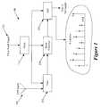
- FIG. 1illustrates a signal processing circuit that receives a GPS signal and generates a number of digital samples from this GPS signal.
- FIG. 2illustrates a process that determines the location of the GPS receiver from the digital samples generated by the signal-processing circuit.
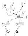
- FIG. 3illustrates a location-determination system
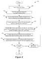
- FIG. 4illustrates a process that calculates the approximate location of GPS satellites at a particular transmission time.
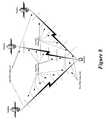
- FIG. 5illustrates one satellite that is “over” an approximate location and another satellite that is not “over” the approximate location.
- FIG. 6illustrates a process that identifies satellites that are over an approximate location.
- FIG. 7illustrates a process that computes phase offsets for several satellites.
- FIG. 8illustrates the type of code segments that a GPS receiver receives from several GPS satellites.
- FIG. 9illustrates a process for computing pseudoranges.
- FIG. 10illustrates a PRN code received by a GPS receiver, a replica of this code stored by the GPS receiver, and a phase-shifted version of this replica.
- the inventionprovides location-determination method and apparatus.
- numerous detailsare set forth for purpose of explanation. However, one of ordinary skill in the art will realize that the invention may be practiced without the use of these specific details. For instance, some embodiments of the invention are described below by reference to global positioning systems. One of ordinary skill will understand that other embodiments of the invention are used in other types of location-determination systems. In other instances, well-known structures and devices are shown in block diagram form in order not to obscure the description of the invention with unnecessary detail.
- a reference signalmeans any type of signal from which location information may be derived.
- the reference signalcan be a GPS (“global positioning system”) signal, a CDMA (“code division multiple access”) signal, a GSM (“global system for mobile communication”) signal, a TDMA (“time division multiple access”) signal, a CDPD (“cellular digital packet data”) signal, or any other signal from which location information may be derived.
- the reference signalis a GPS signal that can be used to estimate the location of GPS receivers.
- a GPS receivertypically receives a GPS signal that is a composite of several signals transmitted by GPS satellites that orbit the Earth. The characteristics of such GPS-satellite signals were described in the background section.
- the GPS receivercan be a standalone device, can be part of another mobile device (e.g., a personal digital assistant (“PDA”), wireless telephone, etc.), or can communicatively connect to another mobile device (e.g., connect to a Handspring Visor PDA through its proprietary Springboard).
- PDApersonal digital assistant
- Several such architectures for the GPS receiverare described in U.S. patent application, entitled “Method and Apparatus for Determining Location Using a Thin-Client Device,” filed on Dec. 4, 2000, and having Ser. No. 09/730,324.
- the disclosure of this applicationi.e., U.S. patent application, entitled “Method and Apparatus for Determining Location Using a Thin-Client Device,” filed on Dec. 4, 2000, and having Ser. No. 09/730,324.
- U.S. patent applicationentitled “Method and Apparatus for Determining Location Using a Thin-Client Device,” filed on Dec.
- Some embodimentsestimate the location of a GPS receiver by (1) initially generating K-digital samples s 1 , . . . , s K from the GPS reference signal received by the receiver, and then (2) using the digitized GPS reference data to estimate the location of the GPS receiver.
- the GPS receivertypically performs the digitization operation. Also, in some embodiments, the GPS receiver digitizes only a portion of the received GPS signal. An example of a signal-processing circuit that a GPS receiver can use to generate such samples will be described below by reference to FIG. 1 .
- Some embodimentsestimate the location of the GPS receiver from the digitized GPS reference data by using a location-determination process that can be performed either (1) completely by the GPS receiver, (2) completely by another device or computer in communication with the GPS receiver, or (3) partially by the GPS receiver and partially by another device or computer in communication with the GPS receiver.
- the location-determination processcomputes pseudoranges for a set of satellites without performing signal tracking on the received GPS reference data. In some of these embodiments, the process computes for each satellite in the set a phase offset between the samples of the received reference signal and a replica of the satellite's PRN code. The system also identifies an approximate location of the receiver and an approximate receive time (e.g., an approximate time for the start of the received signal).
- the systemuses the receiver's approximate location, approximate receive time, and the computed phase offsets to compute pseudoranges for the set of satellites.
- To compute a satellite's pseudorangesome embodiments use the satellite's computed phase offset and the receiver's approximate location to calculate the length of all or most of the PRN codes transmitted by the satellite from the time that it transmitted the signal resulting in the first sample s 1 to the time the receiver generated the first sample s 1 .
- the systemidentifies the estimated location of the receiver by using the computed pseudoranges.
- the estimated receiver locationmatches the exact receiver location. In other circumstances, the estimated receiver location matches the exact receiver location to such a high degree of accuracy that it is indistinguishable from the exact location to an observer. In yet other situations, however, the estimated location differs from the actual location of the GPS receiver by a certain error amount; in these situations, some embodiments take steps to ensure that this error (between the estimated and actual receiver locations) is tolerable for the particular location-determination application. Several more specific location-determination processes will be explained by reference to FIGS. 2-10.
- FIG. 1illustrates a signal processing circuit 100 that receives a GPS signal and generates K-digital samples from the GPS signal.
- the signal processing circuit 100includes a GPS antenna 105 , a GPS tuner 110 , a clock 115 , a down-converter 120 , and an analog to digital (“A/D”) converter 125 .
- GPS antenna 105receives a GPS signal and generates K-digital samples from the GPS signal.
- the signal processing circuit 100includes a GPS antenna 105 , a GPS tuner 110 , a clock 115 , a down-converter 120 , and an analog to digital (“A/D”) converter 125 .
- A/Danalog to digital
- the GPS antenna 105receives a GPS signal ⁇ haeck over (s) ⁇ (t), which on Earth is a composite of noise and several signals transmitted by several GPS satellites that orbit the Earth.
- the antenna 105 and its associated circuitryare configured to receive the reference GPS signal ⁇ haeck over (s) ⁇ (t) at a GPS carrier frequency, which currently is around 1.57 gigahertz (“Ghz”).
- the RF tuner 110receives the GPS signal ⁇ haeck over (s) ⁇ (t) from the antenna 105 . This tuner 110 is tuned to capture signals at the approximate frequency of the GPS signal. Hence, the tuner captures the GPS reference signal ⁇ haeck over (s) ⁇ (t) received by the antenna 105 .
- the RF tunercommunicatively couples to the clock 115 to receive a clock signal.
- the clock 115generates one or more clock signals to synchronize the operation of the components of the signal-processing circuit 100 .
- This clockalso receives a synchronizing clock signal 130 .
- the clock 115can receive the synchronizing signal 130 from a variety of sources.
- the signal-processing circuit 100includes an RF processing circuit that (1) captures a radio signal with the synchronizing signal, and (2) supplies this signal to the clock 115 .
- the synchronizing signalallows the clock to set initially its internal time. It also allows the clock to synchronize with a reference clock.
- the receiveris part of a network (e.g., a wireless telephone network) and its clock 115 is synchronized with the network clock so as to keep the receiver clock within a few micro- or milli-seconds of the GPS clock. Some embodiments synchronize the clock 115 to be within 1 millisecond or less of the GPS clock.
- the degree of the receiver clock's inaccuracywill depend on (1) source and manner of obtaining the synchronizing signal 130 , (2) the accuracy of the clock of the synchronizing-signal source, and (3) the accuracy of the GPS-receiver clock.
- embodimentsuse other techniques to maintain the receiver clock within a desired time interval of GPS time. For instance, some embodiments might have the receiver estimate and compensate for its clock drift internally. Other embodiments use high-precision clocks in their receivers.
- the down converter 120receives the tuner's output (i.e., receives the captured GPS reference signal ⁇ haeck over (s) ⁇ (t)).
- the down converter 120transforms the captured GPS reference signal to an intermediate frequency (“IF”) reference signal ⁇ haeck over (s) ⁇ (t).
- IFintermediate frequency
- the down converterincludes in some embodiments an IF mixer that converts the frequency of the captured GPS signal to an IF frequency, such as 50 Mhz.
- the down converteralso includes one or more band pass and amplification stages to filter and amplify the input and/or output of the IF mixer.
- the signal-processing circuit 100utilizes a down converter so that the A/D converter 125 can sample the reference signal at an intermediate frequency as opposed to a radio frequency.
- a down converterso that the A/D converter 125 can sample the reference signal at an intermediate frequency as opposed to a radio frequency.
- One of ordinary skillwill understand that other embodiments can include more than one down converter in their signal-processing circuits. Also, some embodiments use one or more down converters to convert the GPS reference signal to a baseband reference signal, which can then be sampled by the A/D converter.
- the A/D converter's sampling rateis at least twice the size of the frequency band, while in other embodiments the sampling rate differs from this rate.
- the A/D converter 125samples the IF reference GPS signal ⁇ overscore (s) ⁇ (t) that it receives from the down converter 120 , and outputs K-digital samples s 1 , . . . , s K of the IF GPS signal ⁇ overscore (s) ⁇ (t). These samples are from only a portion of the received GPS signal, and serve as digital GPS reference data that the location determination processes use.
- ⁇ tilde over (t) ⁇ 1represent the receiver clock time recorded when the first sample of the GPS signal is received at the receiver.
- the first-sample time ⁇ tilde over (t) ⁇ 1represents the approximate time for when the first sample was generated because it is measured according to the receiver's clock, which is not completely synchronized with the GPS time in the embodiments described below.
- the A/D converteralso outputs the first-sample time ⁇ tilde over (t) ⁇ 1 .
- a “tilde”is generally placed over a variable (like ⁇ tilde over (t) ⁇ 1 ) to indicate that the value of the variable is an approximation of the actual value of the item represented by the variable.
- FIG. 3illustrates a location-determination server 300 that performs the process 200 .
- this serveris just one computer, while in other embodiments several computers form this server. In some embodiments, these several computers may be geographically distributed.
- This servercan be a standalone device or it can be part of other devices.
- the location-determination server 300receives digital GPS reference data s 1 , . . . , s K from client devices 305 through one or more base stations 310 .
- a client device 305is either a GPS receiver, contains a GPS receiver, or communicatively connects to a GPS receiver.
- each base stationdetects GPS-receiver signal transmissions within a particular region, and relays this information to the location-determination server.
- the base stationcan use a variety of communication architectures and networks to relay the signals from the GPS receivers to the location-determination server.
- the base stationis a cell tower that provides wireless communications to the client device 305 .
- the location-determination server 300performs the process 200 for a particular GPS receiver whenever it receives the digital GPS reference data s 1 , . . . , s K from the particular GPS receiver.
- the server 300uses several other data items to perform process 200 , in some embodiments of the invention. For instance, some embodiments use an approximate location of the GPS receiver to compute pseudoranges for several satellites. In the embodiments described below, the approximate location is represented in terms of a three-dimensional vector ⁇ tilde over (l) ⁇ , which represents a point in an Earth-centered, Earth-fixed coordinate system. Some embodiments specify this approximate location to be within ⁇ 150 Km of the actual GPS receiver location.
- the approximate locationis the location of the base station 310 that relays the GPS reference data generated by the receiver. Some of these embodiments extract the approximate-location information from the signal forwarded by the base station.
- the server 300uses the base-station's identification to retrieve the base-station location information from a storage structure (such as database 315 of FIG. 3) that stores the location of all base stations.
- Other embodimentsdetermine the approximate location ⁇ tilde over (l) ⁇ by measuring signal strength between the base station 310 and the client device 305 , using time-difference of arrival (TDOA), angle of arrival (AOA), and/or sector of arrival (SOA) methods at the base stations.
- TDOAtime-difference of arrival
- AOAangle of arrival
- SOAsector of arrival
- Yet other embodimentsidentify the approximate location as the last GPS-receiver's location that was recorded within a predetermined time interval of the current first-sample time.
- One of ordinary skillwill realize that other embodiments use numerous other approaches to identify the approximate GPS-receiver location.
- the data-processing serveralso needs to have access to differential GPS data, satellite clock-correction data, navigation bits, and ephemeris data.
- the servercan receive such data from a variety of sources. For instance, as shown in FIG. 3, the server can receive such data from one or more reference GPS receivers 320 through one or more communication networks 325 , such as the Internet.
- the location-determination server 300To perform the process 200 for a particular GPS receiver, the location-determination server 300 initially computes (at 205 ) the approximate location of all GPS satellites at the time that these satellites transmitted the signals resulting in the first sample s 1 of the GPS reference data. This computation is further described below in Section II.A by reference to FIG. 4 .
- the processnext identifies (at 210 ) N GPS satellites that are over the GPS receiver's approximate location ⁇ tilde over (l) ⁇ . This identification is further described below in Section II.B by reference to FIGS. 5 and 6. After identifying the N overhead satellites for the approximate location ⁇ tilde over (l) ⁇ , the process 200 computes (at 215 ) phase offsets for P satellites, where P is a number equal to or less than N. This computation is further described below in Section II.C by reference to FIG. 7 .
- each of the P satellitesthe process then computes (at 220 ) a pseudorange from its computed code phase, the GPS-receiver's approximate location, and the satellite's approximate location.
- each satellite's approximate locationis computed based on the approximate first-sample time ⁇ tilde over (t) ⁇ 1 , which is based on the receiver clock.
- the computation of the pseudorangesis further described below in Section II.D by reference to FIGS. 8-10.
- the process 200uses (at 225 ) the computed pseudoranges to calculate the GPS receiver's estimated location.
- Some embodimentsuse triangulation techniques to calculate the GPS receiver's estimated location from the computed pseudoranges, as described below in Section II.E.
- the location-determination process 200initially computes the approximate locations of the satellites at the time that these satellites transmitted the signals that resulted in the first sample s 1 .
- the receivergenerated this first sample at time ⁇ tilde over (t) ⁇ 1 .
- a location y i of a satellite iis for all practical purposes a deterministic function of the GPS time t.
- One set of equations for deriving a satellite's location from ephemeris and differential datais provided in Table 2.3 on page 38 of “Understanding GPS Principles and Applications,” by Elliott Kaplan, Artech House, 1996.
- the computed satellite locationis typically a three-dimensional vector (y i ⁇ 3 ) that is defined in an Earth-centered, Earth-fixed coordinate system.
- the process 200To compute the location of a satellite i, the process 200 needs to first compute the time that this satellite transmitted the signal resulting in the first sample. However, the exact transmission time is difficult to compute without performing signal tracking. Hence, the process 200 computes an approximate transmission time and location for each satellite, instead of computing the precise values of these parameters.
- the exact transmission time for each satellite iequals the actual first-sample time t 1 minus the actual signal-transit delay ⁇ i for the satellite.
- the signal-transit delay ⁇ iis the time between the satellite's transmission of the signal resulting in the first sample s 1 and the receiver's generation of the first sample. Equation (1) illustrates one manner of computing the exact signal transit delay ⁇ i of a satellite i.
- lis the receiver's exact position at first-sample time t 1
- y i (t 1 ⁇ i )is the satellite's precise location at exact transmission time (t 1 ⁇ i )
- cis the speed of light
- ⁇ i ais delay due to atmospheric conditions
- ⁇ ris delay caused by analog processing at the receiver.
- the location-determination process 200can determine atmospheric-delay ⁇ i a by using differential data. It can also retrieve from a storage structure (such as data storage 315 ) the processing-delay ⁇ r associated with each GPS receiver. However, it is difficult to ascertain (1) the exact first-sample time t 1 , (2) the receiver's precise location l at exact first-sample time t 1 , or (3) the satellite's precise location y i (t 1 ⁇ i ) at precise transmission time (t 1 ⁇ i ). Hence, it is difficult to solve the Equation (1) to obtain an exact value for the signal-transit delay ⁇ i .
- the location-determination process 200(at 205 ) computes for each satellite i the approximate signal transit delay ⁇ tilde over ( ⁇ ) ⁇ i of the satellite.
- Equation (2)illustrates one manner of computing an approximate signal-transit delay ⁇ tilde over ( ⁇ ) ⁇ i . This equation assumes that (1) the first-sample time is ⁇ tilde over (t) ⁇ 1 , (2) the receiver is located at the approximate location ⁇ tilde over (l) ⁇ , and (3) the satellite's location at transmission time equals its location at the approximate first-sample time ⁇ tilde over (t) ⁇ 1 .
- some embodimentsuse the base-station tower location as the approximate GPS-receiver location ⁇ tilde over (l) ⁇ , and retrieve the tower location from a database by using the received cell tower identification.
- this processcan thus compute an approximate transmission time ( ⁇ tilde over (t) ⁇ 1 ⁇ tilde over ( ⁇ ) ⁇ i ) based on the approximate first-sample time ⁇ tilde over (t) ⁇ 1 and the satellite's approximated signal-transit delay ⁇ tilde over ( ⁇ ) ⁇ i . Accordingly, for each satellite i, the process computes the satellite's approximate location y i ( ⁇ tilde over (t) ⁇ 1 ⁇ tilde over ( ⁇ ) ⁇ i ) at the computed approximate transmission time ( ⁇ tilde over (t) ⁇ 1 ⁇ tilde over ( ⁇ ) ⁇ i ), by using the ephemeris and differential data. As mentioned above, one set of equations for deriving a satellite's location given ephemeris and differential data are provided in Table 2.3 on page 38 of “Understanding GPS Principles and Applications,” by Elliott Kaplan, Artech House, 1996.
- the approximate satellite location that is computed under this approachis no more than few meters off from the true satellite location at the time of transmission. Approximate location errors of less than 150 km will lead to no loss in accuracy, while errors in the receive time are less than four meters per millisecond. When receiver are part of a network (such as a cellular network), the receiver clocks are much more accurate than one millisecond.
- the symbol ⁇ tilde over (y) ⁇ iis used as shorthand for the approximate satellite location y i ( ⁇ tilde over (t) ⁇ 1 ⁇ tilde over ( ⁇ ) ⁇ i ).
- FIG. 4illustrates a process 400 that uses the above-described approach to calculate the approximate location of each GPS satellite i at the approximate time ( ⁇ tilde over (t) ⁇ 1 ⁇ tilde over ( ⁇ ) ⁇ i ) that the satellite transmitted the signal resulting in the first generated sample.
- This processis used by process 200 at 205 , in some embodiments of the invention.
- the process 400initially selects (at 405 ) a first GPS satellite i from a list of GPS satellites that it has. The process then determines (at 410 ) the signal-processing delay ⁇ r associate with receiver. Some embodiments store in a storage structure the processing-delay ⁇ r associated with each GPS receiver that can be used with the process 200 and the location-determination server 300 . Hence, in these embodiments, the process 400 retrieves from the storage structure the processing-delay ⁇ r associated with the particular GPS receiver at issue.
- the processcomputes (at 415 ) the atmospheric delay ⁇ i a .
- This atmospheric delaycan be derived from the received differential GPS data and the approximate receiver location ⁇ tilde over (l) ⁇ .
- One manner for deriving atmospheric delay at a location from received differential GPS datais disclosed in Chapter 8 of “Understanding GPS Principles and Applications,” by Elliott Kaplan, Artech House, 1996.
- the processthen computes the selected satellite's approximate location y i ( ⁇ tilde over (t) ⁇ 1 ) at the approximate first-sample time ⁇ tilde over (t) ⁇ 1 .
- the processcomputes this location at the time ⁇ tilde over (t) ⁇ 1 from the ephemeris and differential data by using the set of equations provided in Table 2.3 on page 38 of “Understanding GPS Principles and Applications,” by Elliott Kaplan, Artech House, 1996.
- the process 400computes (at 425 ) the approximate signal-transit delay ⁇ tilde over ( ⁇ ) ⁇ i of the selected satellite.
- This processuses the above-described Equation (2) to compute the approximate signal-transit delay ⁇ tilde over ( ⁇ ) ⁇ i from the approximate satellite location y i ( ⁇ tilde over (t) ⁇ 1 ) (computed at 420 ), the signal-processing and atmospheric delays ⁇ r and ⁇ i a (respectively obtained at 410 and 415 ), and the approximate receiver location ⁇ tilde over (l) ⁇ .
- the processcomputes (at 430 ) the approximate transmission time ( ⁇ tilde over (t) ⁇ 1 ⁇ tilde over ( ⁇ ) ⁇ i ) for the selected satellite by subtracting the approximate signal-transit delay ⁇ tilde over ( ⁇ ) ⁇ i (computed at 425 ) from the approximate first-sample time ⁇ tilde over (t) ⁇ 1 .
- the processthen computes (at 440 ) the selected satellite's approximate location ⁇ tilde over (y) ⁇ i at the approximate transmission time ( ⁇ tilde over (t) ⁇ 1 ⁇ tilde over ( ⁇ ) ⁇ i ) computed at 435 .
- the processcomputes this location from the ephemeris and differential data by using the set of equations provided in Table 2.3 on page 38 of “Understanding GPS Principles and Applications,” by Elliott Kaplan, Artech House, 1996.
- the processdetermines (at 440 ) whether the selected satellite is the last GPS satellite on its GPS-satellite list. If not, the process selects (at 445 ) another GPS satellite from this list, and repeats 415 to 435 in order to determine this newly-selected satellite's approximate location. Otherwise, the process end as it has computed location of all the GPS satellites at the approximate time they transmitted their signals that resulted in the first generated sample.
- the process 200identifies (at 210 ) the satellites that are currently “overhead.” In some embodiments, the process 200 identifies the “overhead” satellites by making a simplifying assumption that satellites are overhead relative to the client device 305 if and only if they are overhead relative to the approximate location ⁇ tilde over (l) ⁇ .
- the process 200examines each satellite i and determines whether the satellite is over the approximate location ⁇ tilde over (l) ⁇ .
- the processspecifies a satellite i as an overhead satellite if and only if ⁇ tilde over (l) ⁇ ′ ⁇ tilde over (l) ⁇ tilde over (l) ⁇ ′ ⁇ tilde over (y) ⁇ i .
- the “prime”denotes vector transposition.
- the processdesignates satellite i as an overhead satellite if and only if the inner product of the satellite's approximate position vector s i with the approximate location vector ⁇ tilde over (l) ⁇ is greater than or equal to the inner product of the approximate location vector with itself.
- This designation criterionessentially determines whether the magnitude of the projection of a satellite's approximate position vector y i onto the approximate location vector ⁇ tilde over (l) ⁇ is greater than or equal to the magnitude of the approximate location vector ⁇ tilde over (l) ⁇ . If so, the satellite is an overhead satellite.
- FIG. 5pictorially illustrates this designation criterion.
- This figurepresents a GPS receiver 505 at the approximate location ⁇ tilde over (l) ⁇ on Earth 510 , and two satellites 515 and 520 that orbit the Earth.
- the satellite 515is not an overhead satellite as it is beneath the horizon 525 of the location ⁇ tilde over (l) ⁇ . Accordingly, the magnitude of the projection of its position vector y 515 onto the approximate location vector ⁇ tilde over (l) ⁇ is less than the magnitude of the approximate location vector ⁇ tilde over (l) ⁇ .
- the satellite 520is an overhead satellite as it is above the horizon 525 of the location ⁇ tilde over (l) ⁇ . Hence, the magnitude of the projection of its position vector y 520 onto the approximate location vector ⁇ tilde over (l) ⁇ is greater than the magnitude of the approximate location vector ⁇ tilde over (l) ⁇ .
- FIG. 6illustrates a process 600 that uses the above-described approach to identify the overhead satellites. This process is used by process 200 at 210 , in some embodiments of the invention. As shown in FIG. 6, the process 600 initially computes (at 605 ) the inner product of the approximate location vector ⁇ tilde over (l) ⁇ with itself.
- the process 600next selects (at 610 ) a GPS satellite from a list of GPS satellites that it has. The process then computes (at 615 ) the inner product of the approximate location vector ⁇ tilde over (l) ⁇ with the selected satellite's approximate location vector ⁇ tilde over (y) ⁇ i , which was computed at 205 .
- the processdetermines whether it has examined all the GPS satellites on its list of GPS satellites. If not, the process returns to 610 to select another GPS satellite from this list, and repeats the above-described operations in order to determine whether the newly-selected satellite is an overhead satellite or not.
- phase offsetsFor the overhead satellite.
- One method for computing phase offsetsis described below. However, one of ordinary skill will realize that a variety of other methods may be used to compute phase offsets.
- a phase offset for a satelliteis the phase difference between (1) the satellite's PRN code that is part of the received GPS reference data, and (2) a replica of the satellite's PRN code that is used by process 200 .
- the process 200computes a satellite's phase offset by computing an ambiguity function A i ( ⁇ circumflex over ( ⁇ ) ⁇ , ⁇ circumflex over ( ⁇ ) ⁇ D ), which is the square of the magnitude of the inner product R i ( ⁇ circumflex over ( ⁇ ) ⁇ , ⁇ circumflex over ( ⁇ ) ⁇ D ) between the received GPS reference data with the replica of the satellite's PRN code at various candidate phase offsets ⁇ circumflex over ( ⁇ ) ⁇ and Doppler-shift values ⁇ circumflex over ( ⁇ ) ⁇ D .
- Equations (3) and (4)provide mathematical representations of the ambiguity and correlation functions.
- t kdenotes the GPS time of the k th sample
- ⁇ tilde over (s) ⁇ k ⁇ circumflex over ( ⁇ ) ⁇ Dis the k th sample after the candidate Doppler-shift value has been applied to it
- the candidate Doppler-shift value ⁇ circumflex over ( ⁇ ) ⁇ Drepresents the sum of the satellite Doppler and the clock Doppler values
- ⁇ overscore (x) ⁇ i (t)is a bandpass filtered version of the satellite's C/A code replica x i (t) (modulated by the navigation bits) that the process 200 uses.
- the Doppler-shift valueis applied to the k th sample by multiplying this sample by e ⁇ 2 ⁇ j( ⁇ IF + ⁇ circumflex over ( ⁇ ) ⁇ D )(t k ⁇ t 1 ) .
- the search through candidates( ⁇ circumflex over ( ⁇ ) ⁇ , ⁇ circumflex over ( ⁇ ) ⁇ D ) is exhaustive, and the phase offset of the candidate pair that resulted in the maximum ambiguity value for the satellite is selected as the phase offset of the satellite.
- some embodimentstake this selection a step further.
- These embodimentsuse an ambiguity threshold ratio to detect useful phase offsets, and disregard satellites without useful phase offsets. For instance, some embodiments require a satellite's maximum ambiguity to exceed the average ambiguity by a constant ratio in order for its phase offset to be considered valid. In other embodiments, a variety of threshold tests can be used, such as ratio between highest ambiguity peak and next highest ambiguity peak.
- the process 700enumerates (at 710 ) a number of candidate phase offsets ⁇ circumflex over ( ⁇ ) ⁇ 's and Doppler-shift values ⁇ circumflex over ( ⁇ ) ⁇ D 's for the selected satellite.
- the processselects (at 715 ) a candidate phase offset ⁇ circumflex over ( ⁇ ) ⁇ and Doppler-shift value ⁇ circumflex over ( ⁇ ) ⁇ D , and computes (at 720 ) the ambiguity value for the selected candidate pair by using Equations (3) and (4) above.
- the processtransitions to 750 .
- the processalso transitions to 750 if it determines (at 740 ) that the selected satellite's maximum ambiguity value does not exceed the threshold ambiguity value.
- the processdetermines whether it has examined all the overhead satellites. If not, the process returns to 705 to select another satellite. Otherwise, the process ends.
- signal-transit delayrefers to this time duration (i.e., it is the time between the satellite's transmission of the signal resulting in the first sample s 1 and the receiver's generation of the first sample s 1 ).
- satellite itransmits several PRN codes.
- FIG. 8illustrates that these PRN codes can be grouped in three categories.
- the first categoryis the PRN code segment 805 that contains the signal resulting in the first sample s 1 .
- this PRN code segmentis referred to as the first PRN code segment.
- the first PRN code segment 805is said to be a complete or practically complete segment when the signal resulting in the first sample is part of the first PRN-code chip, and it is said to be a partial segment when the signal resulting in the first sample is part of a chip after the first PRN-code chip.
- the second categoryincludes the full PRN codes 810 that the satellite transmitted after the first PRN code but before the first-sample time. In the discussion below, these PRN codes are referred to as the full PRN codes.
- the third categoryis the PRN code 815 that the satellite is transmitting when the receiver generates the first sample. In the discussion below, this PRN code segment is referred to as the last PRN code segment 815 .
- the last PRN code segment 815is said to be a complete or practically complete segment when at the first-sample time the satellite is transmitting the last chip of this code, and it is said to be a partial segment when at the first-sample time the satellite is transmitting a chip before the last chip of this code
- Equation (5)illustrates one manner of computing the estimated distance between the GPS receiver and the i th satellite by summing the length first, last, and full PRN code segments after accounting for differential corrections and the satellite-clock's error.
- Equation (5)provides the mathematical representation of a pseudorange 92 i for the i th satellite.
- ⁇ ip i +m i l +( cv i +d i ⁇ )+ d i (5)
- (1) p iis the length of the first code segment
- (2) m iis the number of full PRN codes
- (3) lis the full-PRN-code length, which is about 300 Km
- v iis the i th satellite's transmission phase
- (5) cis the speed of light
- (6) cv iis the length of the last PRN code without adjustment for the satellite clock error
- (7) d i ⁇is the satellite-clock-error correction factor
- (8) d iis the atmospheric-error-correction factor.
- Equation (5)(1) the first term (p i ) accounts for the length of the first code segment, (2) the second term (m i l) accounts for the length of the full PRN codes, (3) the third term (cv i +d i ⁇ ) accounts for the length of the last PRN code after adjustment for satellite-clock error, and (4) the fourth term (d i ) accounts for atmospheric delay.
- Equation (6)provides the mathematical representation for computing another pseudorange ⁇ i for the i th satellite. Equation (6) is similar to Equation (5) except that it does not include cv i , which is the last-PRN-code's length without adjustment for satellite clock error. As further described below, the process 900 does not compute cv i , but rather leaves it to a subsequent triangulation operation to account for this term for all the P satellites together.
- the length p i of the first code segment 805 of satellite iis the code length associated with the phase offset ⁇ i of this satellite. Accordingly, this code length is referred to as phase length in the discussion below.
- FIG. 10illustrates the relationship between the phase length and phase offset of satellite i. This figure presents three codes.
- the first code 1005is the i th satellite's PRN code in the received signal. (In this figure, the illustration of the received PRN code disregards degradation and distortion in the received signal.)
- the second codeis a replica 1010 of the i th satellite's PRN code that the location-determination process uses.
- FIG. 10illustrates the length of complete code replica.
- the third codeis a version 1015 of the replica that has been shifted by a phase offset to perfectly match the received code 1005 . As shown in FIG. 10, the phase length associated with the phase offset equals the length of the first code segment in the received signal.
- phase offset ⁇ iis represented as a normalized-time value between 0 to 1
- i th satellite's phase length p iis represented by Equation (7) below:
- the phase lengthcan be expressed differently. For instance, it can be expressed differently when the phase offset is represented differently.
- the number of full PRN codescan be estimated based on the i th satellite's approximate location ⁇ tilde over (y) ⁇ i , the GPS-receiver's approximate location ⁇ tilde over (l) ⁇ , the i th satellite's computed phase length p i , and the PRN-code-length l. Specifically, this number can be estimated by (1) subtracting the satellite's approximate location from the GPS-receiver's approximate location to obtain an approximate distance between the satellite and receiver, (2) subtracting the phase length plus distance correction factor d i ⁇ from this distance, (3) dividing the resulting value by the PRN-code-length l, and (4) rounding the result of the division to the closest integer value. The calculation of the distance correction factor d i ⁇ is discussed in the following subsection. Once the number of full PRN codes is estimated, the length of these codes can be obtained by multiplying this number by the PRN-code-length l, as mentioned above.
- ⁇ iis the satellite-clock error, which in some embodiments is retrieved by the location-determination process from a GPS receiver 320 through the communication networks 325 .
- Equation (6)includes a differential correction factor d i .
- This correction factoris to account for signal-path delays due to atmospheric conditions and other effects.
- This differential correction factorcan be obtained from a variety of sources, including third-party vendors, publicly available data via the communication network 325 (e.g. www.ngs.noaa.gov/CORS/cors-data.html), readings of an independent GPS receiver and other sources.
- the pseudorange-computing process 900 of FIG. 9will now be described. This process initially selects (at 905 ) one of the P satellites that the process 700 selected for computing their pseudoranges. Next, the process uses (at 910 ) the above-described Equation (7) to compute the selected satellite's phase length p i from its phase offset ⁇ i , which was computed by process 700 .
- the processuses (at 915 ) Equation (9) to compute distance correction factor d i ⁇ due to the satellite-clock error.
- some embodimentsretrieve the satellite-clock error ⁇ i from a GPS receiver 320 through the communication networks 325 .
- the processuses Equation (8) to compute the number of the full PRN codes 810 that the selected satellite transmitted after the first PRN code 805 but before the first-sample time.
- the process 900next computes (at 925 ) the length of these full PRN codes by multiplying the number computed at 915 by the PRN-code-length l, which is about 300 Km.
- the processthen identifies an atmospheric-delay correction factor d i .
- the processthen computes (at 935 ) the selected satellite's pseudorange by summing the values computed at 910 , 920 , 925 , and 930 .
- the process 900determines (at 940 ) whether it has generated pseudoranges for all the P satellites identified by process 700 . If not, the process returns to 905 to select the next satellite, and repeat 910 - 935 to compute the newly-selected satellite's pseudorange. Otherwise, the process ends.
- the process 200uses (at 225 ) the computed pseudoranges to calculate the GPS receiver's estimated location.
- Some embodimentsuse triangulation techniques to calculate the GPS receiver's estimated location from the computed pseudoranges.
- these embodimentsdo not perform signal tracking to compute the pseudoranges of satellites. Accordingly, these embodiments are faster than some of the prior techniques. In addition, these embodiments do not need several seconds of GPS data, as they do not extract the satellite time stamps.
Landscapes
- Engineering & Computer Science (AREA)
- Radar, Positioning & Navigation (AREA)
- Remote Sensing (AREA)
- Physics & Mathematics (AREA)
- General Physics & Mathematics (AREA)
- Computer Networks & Wireless Communication (AREA)
- Position Fixing By Use Of Radio Waves (AREA)
Abstract
Description


Claims (28)
Priority Applications (7)
| Application Number | Priority Date | Filing Date | Title |
|---|---|---|---|
| US09/885,870US6525688B2 (en) | 2000-12-04 | 2001-06-20 | Location-determination method and apparatus |
| CNB018062024ACN100442078C (en) | 2000-12-04 | 2001-12-03 | Positioning method and device |
| EP01999830AEP1344085A2 (en) | 2000-12-04 | 2001-12-03 | Location-determination method and apparatus |
| KR1020027009803AKR100657445B1 (en) | 2000-12-04 | 2001-12-03 | Positioning method and apparatus |
| AU2002220135AAU2002220135A1 (en) | 2000-12-04 | 2001-12-03 | Location-determination method and apparatus |
| JP2002548469AJP3921172B2 (en) | 2000-12-04 | 2001-12-03 | Positioning method, pseudorange calculation method, and positioning system |
| PCT/US2001/045828WO2002046786A2 (en) | 2000-12-04 | 2001-12-03 | Location-determination method and apparatus |
Applications Claiming Priority (2)
| Application Number | Priority Date | Filing Date | Title |
|---|---|---|---|
| US73032400A | 2000-12-04 | 2000-12-04 | |
| US09/885,870US6525688B2 (en) | 2000-12-04 | 2001-06-20 | Location-determination method and apparatus |
Related Parent Applications (1)
| Application Number | Title | Priority Date | Filing Date |
|---|---|---|---|
| US73032400AContinuation-In-Part | 2000-08-08 | 2000-12-04 |
Publications (2)
| Publication Number | Publication Date |
|---|---|
| US20020097181A1 US20020097181A1 (en) | 2002-07-25 |
| US6525688B2true US6525688B2 (en) | 2003-02-25 |
Family
ID=27112029
Family Applications (1)
| Application Number | Title | Priority Date | Filing Date |
|---|---|---|---|
| US09/885,870Expired - LifetimeUS6525688B2 (en) | 2000-12-04 | 2001-06-20 | Location-determination method and apparatus |
Country Status (7)
| Country | Link |
|---|---|
| US (1) | US6525688B2 (en) |
| EP (1) | EP1344085A2 (en) |
| JP (1) | JP3921172B2 (en) |
| KR (1) | KR100657445B1 (en) |
| CN (1) | CN100442078C (en) |
| AU (1) | AU2002220135A1 (en) |
| WO (1) | WO2002046786A2 (en) |
Cited By (49)
| Publication number | Priority date | Publication date | Assignee | Title |
|---|---|---|---|---|
| US20030187803A1 (en)* | 2002-03-28 | 2003-10-02 | Pitt Lance Douglas | Location fidelity adjustment based on mobile subscriber privacy profile |
| US6650288B1 (en)* | 2002-05-23 | 2003-11-18 | Telecommunication Systems | Culled satellite ephemeris information for quick assisted GPS location determination |
| US20040078142A1 (en)* | 1999-04-23 | 2004-04-22 | Global Locate Inc. | Method and apparatus for correlating a satellite signal with a reference code |
| US20050168381A1 (en)* | 2003-07-03 | 2005-08-04 | Navcom Technology, Inc. | Polarization sensitive synthetic aperture radar system and method for local positioning |
| US20050195107A1 (en)* | 2004-03-05 | 2005-09-08 | Kotaro Wakamatsu | Satellite positioning apparatus and method |
| US20050210234A1 (en)* | 2004-03-17 | 2005-09-22 | Best Fiona S | Reach-back communications terminal with selectable networking options |
| US20050208986A1 (en)* | 2004-03-17 | 2005-09-22 | Best Fiona S | Four frequency band single GSM antenna |
| US20050210235A1 (en)* | 2004-03-17 | 2005-09-22 | Best Fiona S | Encryption STE communications through private branch exchange (PBX) |
| US20050225482A1 (en)* | 2003-07-03 | 2005-10-13 | Stephens Scott A | Positioning system with co-polarized and cross-polarized mapping |
| US20050237259A1 (en)* | 2003-07-03 | 2005-10-27 | Stephens Scott A | Decoherence plate for use in a communications system |
| US20050270229A1 (en)* | 2003-07-03 | 2005-12-08 | Stephens Scott A | Positioning system with a sparse antenna array |
| US20050270227A1 (en)* | 2003-07-03 | 2005-12-08 | Stephens Scott A | Positioning system with intentional multi-path signal |
| US20050270228A1 (en)* | 2003-07-03 | 2005-12-08 | Stephens Scott A | Radar system for local positioning |
| US7050247B2 (en)* | 2001-11-20 | 2006-05-23 | Canon Kabushiki Kaisha | Optical unit, exposure unit and optical devices |
| US20060224317A1 (en)* | 2003-05-07 | 2006-10-05 | Koninklijke Philips Electronics N.V. | Method of determining a gps position fix and a gps receiver for the same |
| US20060270451A1 (en)* | 2004-03-17 | 2006-11-30 | Best Fiona S | Secure transmission over satellite phone network |
| US20070075848A1 (en)* | 2005-10-05 | 2007-04-05 | Pitt Lance D | Cellular augmented vehicle alarm |
| US20070075849A1 (en)* | 2005-10-05 | 2007-04-05 | Pitt Lance D | Cellular augmented vehicle alarm notification together with location services for position of an alarming vehicle |
| US20070138978A1 (en)* | 2003-06-23 | 2007-06-21 | Advanced Optical Technologies, Llc | Conversion of solid state source output to virtual source |
| US20070164553A1 (en)* | 2006-01-17 | 2007-07-19 | Dov Katz | Coloring book with embedded inwardly foldable stencils |
| US20070207797A1 (en)* | 2006-03-01 | 2007-09-06 | Pitt Lance D | Cellular augmented radar/laser detection using local mobile network within cellular network |
| US20080020783A1 (en)* | 2004-10-15 | 2008-01-24 | Pitt Lance D | Other cell sites used as reference point to cull satellite ephemeris information for quick, accurate assisted locating satellite location determination |
| US20080036655A1 (en)* | 2004-10-15 | 2008-02-14 | Lance Douglas Pitt | Culled satellite ephemeris information based on limiting a span of an inverted cone for locating satellite in-range determinations |
| US7471236B1 (en) | 2006-03-01 | 2008-12-30 | Telecommunication Systems, Inc. | Cellular augmented radar/laser detector |
| US20090015469A1 (en)* | 2004-10-15 | 2009-01-15 | Lance Douglas Pitt | Culled satellite ephemeris information for quick, accurate assisted locating satellite location determination for cell site antennas |
| US20090051590A1 (en)* | 2004-10-15 | 2009-02-26 | Lance Douglas Pitt | Culled satellite ephemeris information for quick, accurate assisted locating satellite location determination for cell site antennas |
| US20090289841A1 (en)* | 2005-02-18 | 2009-11-26 | Mitsubishi Electric Corporation | Positioning apparatus |
| US20100093371A1 (en)* | 2008-10-14 | 2010-04-15 | Todd Gehrke | Location based geo-reminders |
| US20100201569A1 (en)* | 2009-01-06 | 2010-08-12 | Hun Lee | System and method for detecting location using data communication network |
| US20110153632A1 (en)* | 2008-06-27 | 2011-06-23 | Fraunhofer-Gesellschaft Zur Foerderung Der Angewandten Forschung E.V. | Apparatus and method for allocating a current measurement value for a geographical position to a map object |
| US8315599B2 (en) | 2010-07-09 | 2012-11-20 | Telecommunication Systems, Inc. | Location privacy selector |
| US8336664B2 (en) | 2010-07-09 | 2012-12-25 | Telecommunication Systems, Inc. | Telematics basic mobile device safety interlock |
| US8369967B2 (en) | 1999-02-01 | 2013-02-05 | Hoffberg Steven M | Alarm system controller and a method for controlling an alarm system |
| US8525681B2 (en) | 2008-10-14 | 2013-09-03 | Telecommunication Systems, Inc. | Location based proximity alert |
| WO2013184701A1 (en)* | 2012-06-05 | 2013-12-12 | Arun Raghupathy | Systems and methods for location positioning of user device |
| US8629803B2 (en) | 2008-09-10 | 2014-01-14 | Nextnav, Llc | Wide area positioning system |
| US8688174B2 (en) | 2012-03-13 | 2014-04-01 | Telecommunication Systems, Inc. | Integrated, detachable ear bud device for a wireless phone |
| US8874398B2 (en) | 2010-11-12 | 2014-10-28 | Nextnav, Llc | Wide area positioning system |
| US8892495B2 (en) | 1991-12-23 | 2014-11-18 | Blanding Hovenweep, Llc | Adaptive pattern recognition based controller apparatus and method and human-interface therefore |
| US8917209B2 (en) | 2009-09-10 | 2014-12-23 | Nextnav, Llc | Coding in a wide area positioning system (WAPS) |
| US9035829B2 (en) | 2008-09-10 | 2015-05-19 | Nextnav, Llc | Wide area positioning systems and methods |
| US9167553B2 (en) | 2006-03-01 | 2015-10-20 | Telecommunication Systems, Inc. | GeoNexus proximity detector network |
| US9176217B2 (en) | 2011-08-02 | 2015-11-03 | Nextnav, Llc | Cell organization and transmission schemes in a wide area positioning system (WAPS) |
| US9198054B2 (en) | 2011-09-02 | 2015-11-24 | Telecommunication Systems, Inc. | Aggregate location dynometer (ALD) |
| US9286490B2 (en) | 2013-09-10 | 2016-03-15 | Nextnav, Llc | Systems and methods for providing conditional access to transmitted information |
| US9291712B2 (en) | 2009-09-10 | 2016-03-22 | Nextnav, Llc | Cell organization and transmission schemes in a wide area positioning system (WAPS) |
| US9372266B2 (en) | 2009-09-10 | 2016-06-21 | Nextnav, Llc | Cell organization and transmission schemes in a wide area positioning system (WAPS) |
| US9390279B2 (en) | 2012-09-11 | 2016-07-12 | Nextnav, Llc | Systems and methods for providing conditional access to transmitted information |
| US10361802B1 (en) | 1999-02-01 | 2019-07-23 | Blanding Hovenweep, Llc | Adaptive pattern recognition based control system and method |
Families Citing this family (37)
| Publication number | Priority date | Publication date | Assignee | Title |
|---|---|---|---|---|
| US6999430B2 (en)* | 2000-11-30 | 2006-02-14 | Qualcomm Incorporated | Method and apparatus for transmitting data traffic on a wireless communication channel |
| EP1382217B1 (en)* | 2001-04-24 | 2010-04-28 | QUALCOMM Incorporated | Method and apparatus for estimating the position of a terminal based on identification codes for transmission sources |
| FR2826447B1 (en)* | 2001-06-26 | 2003-09-19 | Sagem | HYBRID INERTIAL NAVIGATION METHOD AND DEVICE |
| US7499710B2 (en)* | 2001-08-30 | 2009-03-03 | Alcatel-Lucent Usa Inc. | Integrity monitoring for geo-location systems |
| FI112976B (en)* | 2002-10-08 | 2004-02-13 | Nokia Corp | Positioning method for electronic device e.g. positioning receiver, by converting assistance information to meta data format for subsequent transmission to electronic device which in turn uses the assistance information when necessary |
| KR100498480B1 (en) | 2003-01-23 | 2005-07-01 | 삼성전자주식회사 | Method and apparatus for estimating position utilizing GPS satellite signal |
| US7286624B2 (en)* | 2003-07-03 | 2007-10-23 | Navcom Technology Inc. | Two-way RF ranging system and method for local positioning |
| CN1332215C (en)* | 2003-10-24 | 2007-08-15 | 中兴通讯股份有限公司 | Moving localization method |
| EP1804072B1 (en)* | 2004-02-27 | 2010-04-28 | Research In Motion Limited | Method and apparatus for facilitating the determination of GPS location information for a mobile station without disrupting communications of a voice call |
| US7477906B2 (en)* | 2004-02-27 | 2009-01-13 | Research In Motion Limited | Methods and apparatus for facilitating the determination of GPS location information for a mobile station without disrupting communications of a voice call |
| US7479922B2 (en)* | 2005-03-31 | 2009-01-20 | Deere & Company | Method and system for determining the location of a vehicle |
| US7647177B2 (en)* | 2005-03-31 | 2010-01-12 | Deere & Company | System and method for determining a position of a vehicle |
| US7026992B1 (en) | 2005-03-31 | 2006-04-11 | Deere & Company | Method for configuring a local positioning system |
| US7720598B2 (en)* | 2005-03-31 | 2010-05-18 | Deere & Company | System and method for determining a position of a vehicle with compensation for noise or measurement error |
| US7653483B2 (en)* | 2005-03-31 | 2010-01-26 | Deere & Company | System and method for determining a position of a vehicle |
| US7593811B2 (en)* | 2005-03-31 | 2009-09-22 | Deere & Company | Method and system for following a lead vehicle |
| US8798638B2 (en)* | 2005-07-20 | 2014-08-05 | Qualcomm Incorporated | Methods and apparatus for providing base station position information and using position information to support timing and/or frequency corrections |
| US7991362B2 (en)* | 2005-07-20 | 2011-08-02 | Qualcomm Incorporated | Methods and apparatus for supporting timing and/or frequency corrections in a wireless communications system |
| US7062381B1 (en) | 2005-08-30 | 2006-06-13 | Deere & Company | Method and system for determining relative position of mobile vehicles |
| US7970534B2 (en) | 2006-08-24 | 2011-06-28 | Blackbird Technologies, Inc. | Mobile unit and system having integrated mapping, communications and tracking |
| US7843335B2 (en)* | 2007-03-13 | 2010-11-30 | Blackbird Technologies, Inc. | Mobile asset tracking unit, system and method |
| FR2914430B1 (en)* | 2007-03-29 | 2011-03-04 | Centre Nat Detudes Spatiales Cnes | PROCESS FOR PROCESSING RADIONAVIGATION SIGNALS. |
| US8600406B2 (en)* | 2007-06-01 | 2013-12-03 | ShaoWei Pan | System and method for location determination for mobile clients |
| US7826862B2 (en)* | 2007-06-28 | 2010-11-02 | Symbol Technologies, Inc. | Methods and apparatus for improved locationing in a wireless network |
| JP4798168B2 (en)* | 2008-04-23 | 2011-10-19 | トヨタ自動車株式会社 | Relative position detection device and relative position detection system |
| WO2010034351A1 (en)* | 2008-09-26 | 2010-04-01 | Telecom Italia S.P.A. | Method and system for localizing mobile communications terminals |
| US9279879B2 (en) | 2009-06-26 | 2016-03-08 | Qualcomm Incorporated | Positioning in the presence of passive distributed elements |
| CA2780675A1 (en)* | 2009-11-17 | 2011-05-26 | Topcon Positioning Systems, Inc. | Detection and correction of anomalous measurements and ambiguity resolution in a global navigation satellite system receiver |
| US8538373B2 (en) | 2011-05-25 | 2013-09-17 | Blackbird Technologies, Inc. | Methods and apparatus for emergency tracking |
| US9482742B1 (en) | 2015-05-12 | 2016-11-01 | Qualcomm Incorporated | Positioning reference signal (PRS) generation for multiple transmit antenna systems |
| EP3226034B1 (en)* | 2016-04-01 | 2025-03-26 | Centre National d'Etudes Spatiales | Improved gnss receiver using velocity integration |
| CN106154228B (en)* | 2016-06-17 | 2018-10-19 | 清华大学 | Localization method and its equipment based on no text navigation signal |
| JP6626015B2 (en)* | 2017-01-04 | 2019-12-25 | 株式会社東芝 | Synchronization device, synchronization method, synchronization program, and synchronization system |
| US10641903B2 (en)* | 2017-09-29 | 2020-05-05 | Bnsf Railway Company | Optimized global positioning system correction message for interoperable train control messaging transport |
| CN110161545B (en)* | 2018-02-12 | 2022-04-15 | 清华大学 | Positioning system and method for generating positioning signal |
| CN110333478B (en)* | 2018-03-30 | 2022-05-17 | 华为技术有限公司 | Method for determining arrival angle and departure angle and communication device |
| KR102487201B1 (en)* | 2018-08-24 | 2023-01-10 | 현대자동차 주식회사 | System and method for aiming radar sensor angle |
Citations (2)
| Publication number | Priority date | Publication date | Assignee | Title |
|---|---|---|---|---|
| US6121923A (en)* | 1999-02-19 | 2000-09-19 | Motorola, Inc. | Fixed site and satellite data-aided GPS signal acquisition method and system |
| US6191731B1 (en)* | 1999-08-25 | 2001-02-20 | Trimble Navigation Limited | GPS receiver having a fast time to first fix |
Family Cites Families (5)
| Publication number | Priority date | Publication date | Assignee | Title |
|---|---|---|---|---|
| US5736961A (en)* | 1995-10-06 | 1998-04-07 | Novatel, Inc. | Dual Frequency global positioning system |
| US5874914A (en)* | 1995-10-09 | 1999-02-23 | Snaptrack, Inc. | GPS receiver utilizing a communication link |
| US6118977A (en)* | 1997-09-11 | 2000-09-12 | Lucent Technologies, Inc. | Telecommunications-assisted satellite positioning system |
| US6204808B1 (en)* | 1998-08-13 | 2001-03-20 | Ericsson Inc. | Method and system for aiding GPS receivers via a cellular or PCS network |
| US6408178B1 (en)* | 1999-03-29 | 2002-06-18 | Ericsson Inc. | Systems and methods for resolving GPS pseudo-range ambiguity |
- 2001
- 2001-06-20USUS09/885,870patent/US6525688B2/ennot_activeExpired - Lifetime
- 2001-12-03CNCNB018062024Apatent/CN100442078C/ennot_activeExpired - Fee Related
- 2001-12-03AUAU2002220135Apatent/AU2002220135A1/ennot_activeAbandoned
- 2001-12-03WOPCT/US2001/045828patent/WO2002046786A2/enactiveApplication Filing
- 2001-12-03EPEP01999830Apatent/EP1344085A2/ennot_activeWithdrawn
- 2001-12-03KRKR1020027009803Apatent/KR100657445B1/ennot_activeExpired - Fee Related
- 2001-12-03JPJP2002548469Apatent/JP3921172B2/ennot_activeExpired - Fee Related
Patent Citations (2)
| Publication number | Priority date | Publication date | Assignee | Title |
|---|---|---|---|---|
| US6121923A (en)* | 1999-02-19 | 2000-09-19 | Motorola, Inc. | Fixed site and satellite data-aided GPS signal acquisition method and system |
| US6191731B1 (en)* | 1999-08-25 | 2001-02-20 | Trimble Navigation Limited | GPS receiver having a fast time to first fix |
Cited By (107)
| Publication number | Priority date | Publication date | Assignee | Title |
|---|---|---|---|---|
| US8892495B2 (en) | 1991-12-23 | 2014-11-18 | Blanding Hovenweep, Llc | Adaptive pattern recognition based controller apparatus and method and human-interface therefore |
| US10361802B1 (en) | 1999-02-01 | 2019-07-23 | Blanding Hovenweep, Llc | Adaptive pattern recognition based control system and method |
| US8369967B2 (en) | 1999-02-01 | 2013-02-05 | Hoffberg Steven M | Alarm system controller and a method for controlling an alarm system |
| US9535563B2 (en) | 1999-02-01 | 2017-01-03 | Blanding Hovenweep, Llc | Internet appliance system and method |
| US20040078142A1 (en)* | 1999-04-23 | 2004-04-22 | Global Locate Inc. | Method and apparatus for correlating a satellite signal with a reference code |
| US6795771B2 (en)* | 1999-04-23 | 2004-09-21 | Global Locate, Inc. | Method and apparatus for correlating a satellite signal with a reference code |
| US7050247B2 (en)* | 2001-11-20 | 2006-05-23 | Canon Kabushiki Kaisha | Optical unit, exposure unit and optical devices |
| US8126889B2 (en) | 2002-03-28 | 2012-02-28 | Telecommunication Systems, Inc. | Location fidelity adjustment based on mobile subscriber privacy profile |
| US20030187803A1 (en)* | 2002-03-28 | 2003-10-02 | Pitt Lance Douglas | Location fidelity adjustment based on mobile subscriber privacy profile |
| US6650288B1 (en)* | 2002-05-23 | 2003-11-18 | Telecommunication Systems | Culled satellite ephemeris information for quick assisted GPS location determination |
| US20030218567A1 (en)* | 2002-05-23 | 2003-11-27 | Pitt Lance Douglas | Culled satellite ephemeris information for quick assisted gps location determination |
| US20060224317A1 (en)* | 2003-05-07 | 2006-10-05 | Koninklijke Philips Electronics N.V. | Method of determining a gps position fix and a gps receiver for the same |
| US8560233B2 (en)* | 2003-05-07 | 2013-10-15 | Nxp B.V. | Method of determining a GPS position fix and a GPS receiver for the same |
| JP2006525505A (en)* | 2003-05-07 | 2006-11-09 | コーニンクレッカ フィリップス エレクトロニクス エヌ ヴィ | Method and GPS receiver for GPS positioning |
| US20070138978A1 (en)* | 2003-06-23 | 2007-06-21 | Advanced Optical Technologies, Llc | Conversion of solid state source output to virtual source |
| US20050270227A1 (en)* | 2003-07-03 | 2005-12-08 | Stephens Scott A | Positioning system with intentional multi-path signal |
| US20050168381A1 (en)* | 2003-07-03 | 2005-08-04 | Navcom Technology, Inc. | Polarization sensitive synthetic aperture radar system and method for local positioning |
| US20050270228A1 (en)* | 2003-07-03 | 2005-12-08 | Stephens Scott A | Radar system for local positioning |
| US20050270229A1 (en)* | 2003-07-03 | 2005-12-08 | Stephens Scott A | Positioning system with a sparse antenna array |
| US20050237259A1 (en)* | 2003-07-03 | 2005-10-27 | Stephens Scott A | Decoherence plate for use in a communications system |
| US7385551B2 (en) | 2003-07-03 | 2008-06-10 | Navcom Technology, Inc. | Polarization sensitive synthetic aperture radar system and method for local positioning |
| US20050225482A1 (en)* | 2003-07-03 | 2005-10-13 | Stephens Scott A | Positioning system with co-polarized and cross-polarized mapping |
| US7466262B2 (en) | 2003-07-03 | 2008-12-16 | Navcom Technology, Inc. | Positioning system with a sparse antenna array |
| US7450080B2 (en) | 2003-07-03 | 2008-11-11 | Navcom Technology, Inc. | Decoherence plate for use in a communications system |
| US7315275B2 (en) | 2003-07-03 | 2008-01-01 | Navcom Technology, Inc. | Positioning system with intentional multi-path signal |
| US7427945B2 (en) | 2003-07-03 | 2008-09-23 | Navcom Technology, Inc. | Positioning system with co-polarized and cross-polarized mapping |
| US20050195107A1 (en)* | 2004-03-05 | 2005-09-08 | Kotaro Wakamatsu | Satellite positioning apparatus and method |
| US7295155B2 (en)* | 2004-03-05 | 2007-11-13 | Alpine Electronics, Inc. | Satellite positioning apparatus and method |
| US8913989B2 (en) | 2004-03-17 | 2014-12-16 | Telecommunication Systems, Inc. | Secure transmission over satellite phone network |
| US20100124330A1 (en)* | 2004-03-17 | 2010-05-20 | Best Fiona S | Secure transmission over satellite phone network |
| US20110237247A1 (en)* | 2004-03-17 | 2011-09-29 | Best Fiona S | Secure transmission over satellite phone network |
| US8239669B2 (en) | 2004-03-17 | 2012-08-07 | Telecommunication Systems, Inc. | Reach-back communications terminal with selectable networking options |
| US20050210234A1 (en)* | 2004-03-17 | 2005-09-22 | Best Fiona S | Reach-back communications terminal with selectable networking options |
| US8280466B2 (en) | 2004-03-17 | 2012-10-02 | Telecommunication Systems, Inc. | Four frequency band single GSM antenna |
| US20050208986A1 (en)* | 2004-03-17 | 2005-09-22 | Best Fiona S | Four frequency band single GSM antenna |
| US20050210235A1 (en)* | 2004-03-17 | 2005-09-22 | Best Fiona S | Encryption STE communications through private branch exchange (PBX) |
| US8489874B2 (en) | 2004-03-17 | 2013-07-16 | Telecommunication Systems, Inc. | Encryption STE communications through private branch exchange (PBX) |
| US7890051B2 (en) | 2004-03-17 | 2011-02-15 | Telecommunication Systems, Inc. | Secure transmission over satellite phone network |
| US20060270451A1 (en)* | 2004-03-17 | 2006-11-30 | Best Fiona S | Secure transmission over satellite phone network |
| US20060271779A1 (en)* | 2004-03-17 | 2006-11-30 | Best Fiona S | Faceplate for quick removal and securing of encryption device |
| US7761095B2 (en) | 2004-03-17 | 2010-07-20 | Telecommunication Systems, Inc. | Secure transmission over satellite phone network |
| US7724902B2 (en) | 2004-03-17 | 2010-05-25 | Telecommunication Systems, Inc. | Faceplate for quick removal and securing of encryption device |
| US8681044B2 (en) | 2004-10-15 | 2014-03-25 | Telecommunication Systems, Inc. | Culled satellite ephemeris information for quick, accurate assisted locating satellite location determination for cell site antennas |
| US20080020783A1 (en)* | 2004-10-15 | 2008-01-24 | Pitt Lance D | Other cell sites used as reference point to cull satellite ephemeris information for quick, accurate assisted locating satellite location determination |
| US20100045520A1 (en)* | 2004-10-15 | 2010-02-25 | Lance Douglas Pitt | Culled satellite ephemeris information for quick, accurate assisted locating satellite location determination for cell site antennas |
| US7629926B2 (en) | 2004-10-15 | 2009-12-08 | Telecommunication Systems, Inc. | Culled satellite ephemeris information for quick, accurate assisted locating satellite location determination for cell site antennas |
| US20090051590A1 (en)* | 2004-10-15 | 2009-02-26 | Lance Douglas Pitt | Culled satellite ephemeris information for quick, accurate assisted locating satellite location determination for cell site antennas |
| US20080036655A1 (en)* | 2004-10-15 | 2008-02-14 | Lance Douglas Pitt | Culled satellite ephemeris information based on limiting a span of an inverted cone for locating satellite in-range determinations |
| US7782254B2 (en)* | 2004-10-15 | 2010-08-24 | Telecommunication Systems, Inc. | Culled satellite ephemeris information based on limiting a span of an inverted cone for locating satellite in-range determinations |
| US8089401B2 (en) | 2004-10-15 | 2012-01-03 | Telecommunication Systems, Inc. | Culled satellite ephemeris information for quick, accurate assisted locating satellite location determination for cell site antennas |
| US7489273B2 (en) | 2004-10-15 | 2009-02-10 | Telecommunication Systems, Inc. | Culled satellite ephemeris information for quick, accurate assisted locating satellite location determination for cell site antennas |
| US20090015469A1 (en)* | 2004-10-15 | 2009-01-15 | Lance Douglas Pitt | Culled satellite ephemeris information for quick, accurate assisted locating satellite location determination for cell site antennas |
| US7411546B2 (en) | 2004-10-15 | 2008-08-12 | Telecommunication Systems, Inc. | Other cell sites used as reference point to cull satellite ephemeris information for quick, accurate assisted locating satellite location determination |
| US20090289841A1 (en)* | 2005-02-18 | 2009-11-26 | Mitsubishi Electric Corporation | Positioning apparatus |
| US7764227B2 (en)* | 2005-02-18 | 2010-07-27 | Mitsubishi Electric Corporation | Positioning apparatus |
| US7825780B2 (en) | 2005-10-05 | 2010-11-02 | Telecommunication Systems, Inc. | Cellular augmented vehicle alarm notification together with location services for position of an alarming vehicle |
| US20070075849A1 (en)* | 2005-10-05 | 2007-04-05 | Pitt Lance D | Cellular augmented vehicle alarm notification together with location services for position of an alarming vehicle |
| US20070075848A1 (en)* | 2005-10-05 | 2007-04-05 | Pitt Lance D | Cellular augmented vehicle alarm |
| US20070164553A1 (en)* | 2006-01-17 | 2007-07-19 | Dov Katz | Coloring book with embedded inwardly foldable stencils |
| US8515414B2 (en) | 2006-03-01 | 2013-08-20 | Telecommunication Systems, Inc. | Cellular augmented radar/laser detection using local mobile network within cellular network |
| US20090079614A1 (en)* | 2006-03-01 | 2009-03-26 | Lance Douglas Pitt | Cellular augmented radar/laser detector |
| US20110149933A1 (en)* | 2006-03-01 | 2011-06-23 | Lance Douglas Pitt | Cellular augmented radar/laser detection using local mobile network within cellular network |
| US7471236B1 (en) | 2006-03-01 | 2008-12-30 | Telecommunication Systems, Inc. | Cellular augmented radar/laser detector |
| US20070207797A1 (en)* | 2006-03-01 | 2007-09-06 | Pitt Lance D | Cellular augmented radar/laser detection using local mobile network within cellular network |
| US7965222B2 (en) | 2006-03-01 | 2011-06-21 | Telecommunication Systems, Inc. | Cellular augmented radar/laser detector |
| US7899450B2 (en) | 2006-03-01 | 2011-03-01 | Telecommunication Systems, Inc. | Cellular augmented radar/laser detection using local mobile network within cellular network |
| US9167553B2 (en) | 2006-03-01 | 2015-10-20 | Telecommunication Systems, Inc. | GeoNexus proximity detector network |
| US9002347B2 (en) | 2006-03-01 | 2015-04-07 | Telecommunication Systems, Inc. | Transmitter augmented radar/laser detection using local mobile network within a wide area network |
| US7764219B2 (en) | 2006-03-01 | 2010-07-27 | Telecommunication Systems, Inc. | Cellular augmented radar/laser detector |
| US20090015461A1 (en)* | 2006-03-01 | 2009-01-15 | Lance Douglas Pitt | Cellular augmented radar/laser detector |
| US20110153632A1 (en)* | 2008-06-27 | 2011-06-23 | Fraunhofer-Gesellschaft Zur Foerderung Der Angewandten Forschung E.V. | Apparatus and method for allocating a current measurement value for a geographical position to a map object |
| US8392108B2 (en) | 2008-06-27 | 2013-03-05 | Fraunhofer-Gesellschaft Zur Foerderung Der Angewandten Forschung E.V. | Apparatus and method for allocating a current measurement value for a geographical position to a map object |
| US11705936B2 (en) | 2008-09-10 | 2023-07-18 | Nextnav, Llc | Wide area positioning system |
| US8643540B2 (en) | 2008-09-10 | 2014-02-04 | Nextnav, Llc | Wide area positioning system |
| US9408024B2 (en) | 2008-09-10 | 2016-08-02 | Nextnav, Llc | Wide area positioning system |
| US8629803B2 (en) | 2008-09-10 | 2014-01-14 | Nextnav, Llc | Wide area positioning system |
| US11115078B2 (en) | 2008-09-10 | 2021-09-07 | Nextnav, Llc | Wide area positioning system |
| US12289131B2 (en) | 2008-09-10 | 2025-04-29 | Nextnav, Llc | Wide area positioning system |
| US9035829B2 (en) | 2008-09-10 | 2015-05-19 | Nextnav, Llc | Wide area positioning systems and methods |
| US20100093371A1 (en)* | 2008-10-14 | 2010-04-15 | Todd Gehrke | Location based geo-reminders |
| US9467810B2 (en) | 2008-10-14 | 2016-10-11 | Telecommunication Systems, Inc. | Location based geo-reminders |
| US8892128B2 (en) | 2008-10-14 | 2014-11-18 | Telecommunication Systems, Inc. | Location based geo-reminders |
| US8525681B2 (en) | 2008-10-14 | 2013-09-03 | Telecommunication Systems, Inc. | Location based proximity alert |
| US7973708B2 (en)* | 2009-01-06 | 2011-07-05 | Telace Inc. | System and method for detecting location using data communication network |
| US20100201569A1 (en)* | 2009-01-06 | 2010-08-12 | Hun Lee | System and method for detecting location using data communication network |
| US9119165B2 (en) | 2009-09-10 | 2015-08-25 | Nextnav, Llc | Coding in a wide area positioning system (WAPS) |
| US11650330B2 (en) | 2009-09-10 | 2023-05-16 | Nextnav, Llc | Coding in a positioning system |
| US8917209B2 (en) | 2009-09-10 | 2014-12-23 | Nextnav, Llc | Coding in a wide area positioning system (WAPS) |
| US9372266B2 (en) | 2009-09-10 | 2016-06-21 | Nextnav, Llc | Cell organization and transmission schemes in a wide area positioning system (WAPS) |
| US9057606B2 (en) | 2009-09-10 | 2015-06-16 | Nextnav, Llc | Wide area positioning system |
| US9291712B2 (en) | 2009-09-10 | 2016-03-22 | Nextnav, Llc | Cell organization and transmission schemes in a wide area positioning system (WAPS) |
| US9204294B2 (en) | 2010-07-09 | 2015-12-01 | Telecommunication Systems, Inc. | Location privacy selector |
| US8336664B2 (en) | 2010-07-09 | 2012-12-25 | Telecommunication Systems, Inc. | Telematics basic mobile device safety interlock |
| US8315599B2 (en) | 2010-07-09 | 2012-11-20 | Telecommunication Systems, Inc. | Location privacy selector |
| US8874398B2 (en) | 2010-11-12 | 2014-10-28 | Nextnav, Llc | Wide area positioning system |
| US11047991B2 (en) | 2011-06-28 | 2021-06-29 | Nextnav, Llc | Coding in a positioning system |
| US9176217B2 (en) | 2011-08-02 | 2015-11-03 | Nextnav, Llc | Cell organization and transmission schemes in a wide area positioning system (WAPS) |
| US9198054B2 (en) | 2011-09-02 | 2015-11-24 | Telecommunication Systems, Inc. | Aggregate location dynometer (ALD) |
| US9402158B2 (en) | 2011-09-02 | 2016-07-26 | Telecommunication Systems, Inc. | Aggregate location dynometer (ALD) |
| US8688174B2 (en) | 2012-03-13 | 2014-04-01 | Telecommunication Systems, Inc. | Integrated, detachable ear bud device for a wireless phone |
| WO2013184701A1 (en)* | 2012-06-05 | 2013-12-12 | Arun Raghupathy | Systems and methods for location positioning of user device |
| EP3139193A1 (en)* | 2012-06-05 | 2017-03-08 | NextNav, LLC | Systems and methods for location positioning of user device |
| AU2013271771B2 (en)* | 2012-06-05 | 2016-07-28 | Nextnav, Llc | Systems and methods for location positioning of user device |
| US9247392B2 (en) | 2012-06-05 | 2016-01-26 | Nextnav, Llc | Systems and methods for location positioning of user device |
| CN104583802A (en)* | 2012-06-05 | 2015-04-29 | 耐克斯特纳威公司 | Systems and methods for location positioning of user device |
| US9390279B2 (en) | 2012-09-11 | 2016-07-12 | Nextnav, Llc | Systems and methods for providing conditional access to transmitted information |
| US9286490B2 (en) | 2013-09-10 | 2016-03-15 | Nextnav, Llc | Systems and methods for providing conditional access to transmitted information |
Also Published As
| Publication number | Publication date |
|---|---|
| KR100657445B1 (en) | 2007-02-28 |
| KR20030007405A (en) | 2003-01-23 |
| CN1416530A (en) | 2003-05-07 |
| EP1344085A2 (en) | 2003-09-17 |
| US20020097181A1 (en) | 2002-07-25 |
| AU2002220135A1 (en) | 2002-06-18 |
| JP2004515766A (en) | 2004-05-27 |
| CN100442078C (en) | 2008-12-10 |
| WO2002046786A3 (en) | 2002-10-31 |
| JP3921172B2 (en) | 2007-05-30 |
| WO2002046786A2 (en) | 2002-06-13 |
Similar Documents
| Publication | Publication Date | Title |
|---|---|---|
| US6525688B2 (en) | Location-determination method and apparatus | |
| US6525687B2 (en) | Location-determination method and apparatus | |
| US6285316B1 (en) | Locating a mobile unit using signals from both mobile beacons and stationary beacons | |
| CN1979216B (en) | Method and apparatus for estimating velocity of a terminal in a wireless communication system | |
| US7471244B2 (en) | Monitor units for television signals | |
| US8255160B2 (en) | Integrated mobile terminal navigation | |
| US20250116781A1 (en) | TDOA-Based Positioning System Using Low-Earth-Orbit-Based Satellites | |
| US7602334B1 (en) | Method and system of a mobile subscriber estimating position | |
| EP1148344A1 (en) | Positioning of a wireless terminal with satellite positioning signals or base station signals | |
| US20080272909A1 (en) | Position detection with frequency smoothing | |
| WO2000065367A1 (en) | Method and apparatus for locating and providing services to mobile devices | |
| US6476762B2 (en) | Method for performing positioning and an electronic device | |
| EP1160582A2 (en) | Method and device for determining the phase of information, and its use in a positioning system | |
| US6417800B1 (en) | Method for determining reference time error and an electronic device | |
| US7403155B2 (en) | Method for the accelerated acquisition of satellite signals | |
| KR20020076254A (en) | Locating a mobile unit using coherently processed satellite signals combined with signals from stationary beacons | |
| US6985542B1 (en) | Coherent processing of satellite signals to locate a mobile unit | |
| JP2005221331A (en) | GPS receiver | |
| US6433733B2 (en) | Method for determining the position of an object, a positioning system, a receiver and an electronic device | |
| JP2013127470A (en) | Method of positioning receiver, positioning system, and electronic apparatus | |
| US20030224802A1 (en) | Locating a mobile unit | |
| US20060031696A1 (en) | Method and apparatus for determining time | |
| KR100880716B1 (en) | Transient Delay Estimation Using Total Received Power | |
| EP1735633B1 (en) | System and method for location-finding using communication signals | |
| HK1100576A (en) | Method and apparatus for estimating velocity of a terminal in a wireless communication system |
Legal Events
| Date | Code | Title | Description |
|---|---|---|---|
| AS | Assignment | Owner name:ENUVIS, INC., CALIFORNIA Free format text:ASSIGNMENT OF ASSIGNORS INTEREST;ASSIGNORS:CHOU, ANDREW CHOU;VAN ROY, BENJAMIN;TSITSIKLIS, JOHN;REEL/FRAME:012493/0942;SIGNING DATES FROM 20010920 TO 20011008 | |
| STCF | Information on status: patent grant | Free format text:PATENTED CASE | |
| AS | Assignment | Owner name:SIRF TECHNOLOGY HOLDINGS, INC., CALIFORNIA Free format text:MERGER;ASSIGNOR:ENUVIS, INC.;REEL/FRAME:014491/0784 Effective date:20030214 | |
| FPAY | Fee payment | Year of fee payment:4 | |
| AS | Assignment | Owner name:SIRF TECHNOLOGY, INC., CALIFORNIA Free format text:ASSIGNMENT OF ASSIGNORS INTEREST;ASSIGNOR:SIRF TECHNOLOGY HOLDINGS, INC.;REEL/FRAME:017663/0053 Effective date:20060522 | |
| AS | Assignment | Owner name:TEXAS CAPITAL BANK, NATIONAL ASSOCIATION, TEXAS Free format text:SECURITY AGREEMENT;ASSIGNOR:TWR LIGHTING, INC.;REEL/FRAME:023319/0539 Effective date:20090929 | |
| FEPP | Fee payment procedure | Free format text:PAT HOLDER NO LONGER CLAIMS SMALL ENTITY STATUS, ENTITY STATUS SET TO UNDISCOUNTED (ORIGINAL EVENT CODE: STOL); ENTITY STATUS OF PATENT OWNER: LARGE ENTITY | |
| FPAY | Fee payment | Year of fee payment:8 | |
| AS | Assignment | Owner name:CSR TECHNOLOGY INC., CALIFORNIA Free format text:CHANGE OF NAME;ASSIGNOR:SIRF TECHNOLOGY, INC.;REEL/FRAME:027437/0324 Effective date:20101119 | |
| FPAY | Fee payment | Year of fee payment:12 | |
| AS | Assignment | Owner name:ENUVIS, INC., CALIFORNIA Free format text:MERGER;ASSIGNOR:SIRF ACQUISITION CORP.;REEL/FRAME:045410/0443 Effective date:20030328 Owner name:CSR TECHNOLOGY HOLDINGS, INC., CALIFORNIA Free format text:MERGER;ASSIGNOR:ENUVIS, INC.;REEL/FRAME:045410/0568 Effective date:20130925 |