US6524320B2 - Cannula for receiving surgical instruments - Google Patents
Cannula for receiving surgical instrumentsDownload PDFInfo
- Publication number
- US6524320B2 US6524320B2US09/855,358US85535801AUS6524320B2US 6524320 B2US6524320 B2US 6524320B2US 85535801 AUS85535801 AUS 85535801AUS 6524320 B2US6524320 B2US 6524320B2
- Authority
- US
- United States
- Prior art keywords
- slot
- tubular portion
- cannula
- guide member
- tubular
- Prior art date
- Legal status (The legal status is an assumption and is not a legal conclusion. Google has not performed a legal analysis and makes no representation as to the accuracy of the status listed.)
- Expired - Lifetime, expires
Links
- 238000001356surgical procedureMethods0.000claimsabstractdescription9
- 238000002674endoscopic surgeryMethods0.000description5
- 238000012976endoscopic surgical procedureMethods0.000description5
- 239000000463materialSubstances0.000description4
- 239000012530fluidSubstances0.000description3
- 230000002262irrigationEffects0.000description3
- 238000003973irrigationMethods0.000description3
- 238000005452bendingMethods0.000description2
- 239000011248coating agentSubstances0.000description2
- 238000000576coating methodMethods0.000description2
- 230000004313glareEffects0.000description2
- 238000012986modificationMethods0.000description2
- 230000004048modificationEffects0.000description2
- 229910001220stainless steelInorganic materials0.000description2
- 239000010935stainless steelSubstances0.000description2
- 239000004677NylonSubstances0.000description1
- 230000008602contractionEffects0.000description1
- 229920001778nylonPolymers0.000description1
- 239000004033plasticSubstances0.000description1
Images


Classifications
- A—HUMAN NECESSITIES
- A61—MEDICAL OR VETERINARY SCIENCE; HYGIENE
- A61B—DIAGNOSIS; SURGERY; IDENTIFICATION
- A61B17/00—Surgical instruments, devices or methods
- A61B17/34—Trocars; Puncturing needles
- A61B17/3417—Details of tips or shafts, e.g. grooves, expandable, bendable; Multiple coaxial sliding cannulas, e.g. for dilating
- A61B17/3421—Cannulas
- A61B17/3439—Cannulas with means for changing the inner diameter of the cannula, e.g. expandable
- A—HUMAN NECESSITIES
- A61—MEDICAL OR VETERINARY SCIENCE; HYGIENE
- A61B—DIAGNOSIS; SURGERY; IDENTIFICATION
- A61B17/00—Surgical instruments, devices or methods
- A61B17/02—Surgical instruments, devices or methods for holding wounds open, e.g. retractors; Tractors
- A61B17/0293—Surgical instruments, devices or methods for holding wounds open, e.g. retractors; Tractors with ring member to support retractor elements
Definitions
- the present inventionrelates to a cannula for receiving surgical instruments for performing a surgical procedure on a body.
- U.S. Pat. No. 6,187,000discloses a cannula having an expandable portion.
- the expandable portionhas a slot and a guide member disposed in the slot.
- the guide memberis movable from a first terminal end of the slot to a second terminal end of the slot to enable the cross-sectional area of a passage in the cannula to increase.
- the present inventionis a cannula for receiving surgical instruments for performing a surgical procedure on a body.
- the cannulaincludes a tube structure defining a passage through which the surgical instruments are inserted into the body.
- the tube structureincludes an expandable portion for enabling an increase in the cross-sectional area of the passage.
- the expandable portion of the tube structurehas a slot and a guide member disposed in the slot.
- the guide memberis movable from a first end of the slot toward a second end of the slot to enable the cross-sectional area of the passage to increase.
- the expandable portionhas a stop between the first and second ends of the slot engageable with the guide member. The stop retains the guide member in a position relative to the slot and resists movement of the guide member relative to the slot from the position.
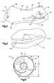
- FIG. 1is an exploded perspective view of a surgical cannula constructed in accordance with a first embodiment of the present invention, the cannula being shown in an expanded condition;
- FIG. 2is a perspective view of the cannula of FIG. 1, the cannula being shown in a contracted condition;
- FIG. 3is a rollout view of an arcuate segment of the cannula of FIG. 1;
- FIG. 4is an enlarged view of a slot in the arcuate segment of FIG. 3;
- FIG. 5is a schematic end view showing the cannula of FIG. 1 in the expanded condition
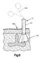
- FIG. 6is a schematic sectional view of the cannula of FIG. 1 during a surgical procedure
- FIG. 7is a schematic perspective view of a surgical cannula constructed in accordance with a second embodiment of the present invention, the cannula being shown in an expanded condition;
- FIG. 8is a rollout view of an arcuate segment of the cannula of FIG. 7;
- FIG. 9is a schematic perspective view of a surgical cannula constructed in accordance with a third embodiment of the present invention, the cannula being shown in an expanded condition;
- FIG. 10is a rollout view of an arcuate segment of the cannula of FIG. 9;
- FIG. 11is a schematic perspective view of a surgical cannula constructed in accordance with a fourth embodiment of the present invention, the cannula being shown in an expanded condition;
- FIG. 12is an enlarged rollout view of an arcuate segment of the cannula of FIG. 11;
- FIG. 13is a schematic sectional view of a surgical cannula constructed in accordance with a fifth embodiment of the present invention.
- the present inventionis directed to a cannula for receiving surgical instruments during a surgical procedure.
- the present inventionis applicable to a variety of surgical procedures in which endoscopic surgical techniques are used.
- FIG. 1illustrates a cannula 10 constructed according to a first embodiment of the present invention.
- the cannula 10is a tubular structure 12 centered on an axis 14 .
- the tubular structure 12defines a passage 16 through the cannula 10 .
- Surgical instrumentsare inserted into the body during endoscopic surgery through the passage 16 .
- the tubular structure 12comprises a first tubular portion 20 and a second tubular portion 40 attached to the first tubular portion.
- the first tubular portion 20is preferably made of a length of stainless steel tubing, but could alternatively be made of another suitable material, such as a radiolucent material.
- the first tubular portion 20has a proximal end 22 and a distal end 24 .
- Parallel cylindrical inner and outer surfaces 26 and 28extend between the ends 22 , 24 of the first tubular portion 20 .
- the first tubular portion 20has a thickness measured perpendicular to the surfaces 26 and 28 in the range of 0.02 inches to 0.04 inches or approximately 0.5 mm to approximately 1.0 mm.
- the inner surface 26defines a first passage portion 30 of the passage 16 through the cannula 10 .
- the first passage portion 30has a diameter D 1 which is preferably in the range from 10 mm to 20 mm or approximately 0.4 inches to approximately 0.8 inches.
- the inner surface 26may have a non-reflective coating to reduce glare on any video image produced by a video camera inserted through the passage 16 .
- the second tubular portion 40 of the tubular structure 12is attached to the distal end 24 of the first tubular portion 20 .
- the second tubular portion 40is preferably made from stainless steel, but could alternatively be made from another suitable material, such as a radiolucent material.
- the second tubular portion 40includes an arcuate segment 42 of sheet stock.
- the arcuate segment 42includes first and second edges 44 and 46 .
- the arcuate segment 42also includes first and second planar edges 48 and 50 extending between the edges 44 and 46 .
- the first and second planar edges 48 and 50are rolled in an overlapping manner to form the tubular configuration of the second tubular portion 40 .
- first and second edges 44 and 46define oppositely disposed first and second ends 60 and 62 of the second tubular portion.
- the first and second ends 60 and 62are connected by a central portion 64 .
- the first end 60 of the second tubular portion 40is attached to the distal end 24 of the first tubular portion 20 by a suitable fastener, such as a rivet 66 . It is contemplated that a screw could be used instead of the rivet 66 .
- the rivet 66extends through two aligned apertures 68 at the first end 60 of the second tubular portion 40 .
- the rivet 66has a first portion 70 and a second portion 72 .
- the first portion 70has a shaft 74 extending from a head 76 .
- the shaft 74extends through the apertures 68 in the tubular portion 40 and the head 76 engages the inner surface 26 of the first tubular portion 20 .
- a cylindrical opening 78extends through the shaft 74 and the head 76 .
- the second portion 72 of the rivet 66has a shaft 80 extending from a head 82 .
- the shaft 80extends into the opening 78 in the first portion 68 of the rivet 66 and the head 82 engages the second tubular portion 40 .
- the shaft 80 of the second portion 72extends into the opening 78 in the first portion 70 to connect the first and second portions of the rivet 66 and pivotally connect the second tubular portion 40 to the first tubular portion 20 .
- the second tubular portion 40(FIG. 1) includes parallel inner and outer surfaces 90 and 92 extending between the first and second ends 60 and 62 .
- the inner surface 90defines a second passage portion 94 of the passage 16 through the cannula 10 which extends as a continuation of the first passage portion 30 in the first tubular portion 20 .
- the second tubular portion 40has a thickness measured perpendicular to the surfaces 90 and 92 in the range of 0.003 inches to 0.005 inches or approximately 0.075 mm to approximately 0.125 mm.
- the inner surfacemay have a non-reflective coating that reduces glare on any video image produced by a camera inserted through the passage 16 .
- An arcuate slot 100(FIGS. 1 and 3) is formed in the second tubular portion 40 and extends between the inner and outer surfaces 90 and 92 of the second tubular portion.
- the arcuate slot 100extends in a direction along a curvilinear path in the central portion 64 of the second tubular portion 40 toward the end 62 of the second tubular portion.
- the arcuate slot 100has a first end 102 located in the central portion 64 of the second tubular portion 40 .
- a second end 104 of the arcuate slot 100is located adjacent the intersection of the second edge 46 and the planar edge 48 of the arcuate segment 42 .
- the arcuate slot 100(FIGS. 3 and 4) has three notches or stops 106 between the ends 102 and 104 .
- the notches 106define three expanded conditions of the second tubular portion 40 .
- the notches 106extend in directions transverse to the arcuate direction in which the slot 100 extends. Although the present invention shows three stops 106 , it is contemplated that the slot could have any number of stops.
- a guide member or rivet 114(FIGS. 1 and 3) is attached to the inner surface 90 of the second tubular portion 40 adjacent the intersection of the second edge 46 and the planar edge 50 . It is contemplated that a guide pin or screw could be used instead of the rivet 114 . In the tubular configuration of the second tubular portion 40 , the guide member 114 is located in the arcuate slot 100 and is movable along the curvilinear path of the arcuate slot.
- the rivet 114(FIG. 1) is generally similar to the rivet 66 and, therefore, will not be described in detail.
- the rivet 114has a first portion 116 and a second portion 118 .
- the first portion 116has a shaft 120 extending from a head 122 .
- the shaft 120extends through the slot 100 and the head 122 engages a washer 124 .
- a cylindrical opening 126extends through the shaft 120 and the head 122 .
- the second portion 118 of the rivet 114has a shaft 128 extending from a head 130 .
- the shaft 128extends into the opening 126 in the first portion 116 of the rivet 114 and the head 130 engages the outer surface 92 of the second tubular portion 40 .
- the shaft 120extends into the opening 126 to connect the first portion 116 of the rivet 114 to the second portion 118 .
- the second tubular portion 40 of the tubular structure 12is expandable from a contracted condition, shown in FIG. 2, to any one of three expanded conditions, one of which is shown in FIG. 1 .
- the guide member 114In the contracted condition, the guide member 114 is located in the first end 102 of the arcuate slot 100 in the second tubular portion 40 .
- the second passage portion 94 defined by the second tubular portion 40is cylindrical in shape.
- the second passage portion 94has a generally constant diameter D 2 which is approximately equal to the diameter D 1 of the first tubular portion 20 .
- the cross-sectional area of the second passage portion 94 at the second end 62 of the second tubular portion 40is approximately the same as the cross-sectional area at the first end 60 of the second tubular portion and is approximately the same as the cross-sectional area of the first passage portion 30 in the first tubular portion 20 .
- the guide member 114engages one of the stops 106 and is located in one of the notches 106 in the arcuate slot 100 in the second tubular portion 40 . It is also contemplated that the guide member 114 could engage one of the stops 106 and be located between adjacent notches 106 .
- the stops 106retain the guide member 114 in one of a plurality of positions relative to the slot 100 and resist movement of the guide member from one of the plurality of positions relative to the slot. Accordingly, the stops 106 resist contraction of the second tubular portion 40 .
- the second tubular portion 40has a conical configuration when in the expanded conditions.
- the second passage portion 94has a diameter D 3 which is larger than the diameter D 2 of the second passage portion at the first end 60 .
- the cross-sectional area of the second passage portion 94 at the second end 62 of the second tubular portion 40is greater than the cross-sectional area of the second passage portion at the first end 60 of the second tubular portion.
- the cannula 10may include an outer member (not shown) for maintaining the second tubular portion 40 of the cannula in the contracted condition. It is contemplated that other suitable means for maintaining the second tubular portion 40 in the contracted condition could be employed.
- the outer membermay be a layer of plastic tubing which is heat shrunk over both the first and second tubular portions 20 and 40 to hold the second tubular portion in the contracted condition.
- a loop of nylon string(not shown) for tearing the heat shrink tubing is wrapped around the heat shrink tubing so that it extends both underneath and on top of the tubing. An outer end of the string extends beyond the tubing.
- the cannula 10(FIG. 6) is inserted through an incision into a body 138 of a patient in the contracted condition.
- the second tubular portion 40is inserted inside the body 138 .
- the first tubular portion 20is inserted into the incision so that the first tubular portion extends from an exterior of the body 138 to inside the body.
- the outer end of the stringis then manually pulled on by the surgeon. Pulling on the string tears the heat shrink tubing.
- the heat shrink tubingremains on the cannula 10 . With the heat shrink tubing torn, the second tubular portion 40 of the cannula 10 is thereby released for expansion toward one of the expanded conditions.
- an expansion tool(not shown) is inserted into the passage 16 in the cannula 10 .
- the expansion toolis manually operated, causing a radially outwardly directed force to be exerted on the inner surface 90 of the second tubular portion 40 by the tool.
- the second tubular portion 40expands toward one of the expanded conditions.
- the guide member 114slides from the first end 102 of the arcuate slot 100 toward the second end 102 of the arcuate slot to permit the expansion of the second tubular portion 40 .
- the guide member 114engages a first stop 106 to position the guide member relative to the slot 100 . If the second tubular portion 40 needs to be expanded further, additional force is applied to the second tubular portion to move the guide member 114 .
- Expansion of the second tubular portion 40can be stopped when the guide member 114 engages one of the stops 106 .
- the guide member 114engages the stops 106 to position the guide member in any one of the plurality of positions relative to the slot 100 .
- the stops 106resist movement of the guide member 114 relative to the slot 100 .
- the second tubular portion 40has a plurality of expanded conditions.
- the expansion toolis then removed so that one or more surgical instruments (indicated schematically at 140 in FIG. 6) can be received through the cannula 10 and inserted into a patient's body 138 .
- the expandable second tubular portion 40 of the cannula 10provides a large working area for the surgeon inside the body 140 within the confines of the cannula. Furthermore, the second tubular portion 40 provides a working area that is only as large as needed. As a result, the simultaneous use of a number of endoscopic surgical instruments, including but not limited to steerable instruments, shavers, dissectors, scissors, forceps, retractors, dilators, and video cameras, is made possible by the expandable cannula 10 .
- FIGS. 7-8A cannula 210 constructed according to a second embodiment of the present invention is illustrated in FIGS. 7-8.
- the cannula 210includes a tubular structure 212 .
- the tubular structure 212defines a passage 216 through the cannula 210 .
- Surgical instrumentsare inserted into the body during endoscopic surgery through the passage 216 .
- the tubular structure 212comprises a first tubular portion 220 and a second tubular portion 240 attached to the first tubular portion.
- the first tubular portion 220is identical to the first tubular portion 20 described in connection with the embodiment disclosed in FIGS. 1-6. Accordingly, the first tubular portion 220 will not be described in detail.
- the second tubular portion 240 of the tubular structure 212is attached to a distal end 224 of the first tubular portion 220 .
- the second tubular portion 240includes an arcuate segment 242 of sheet stock.
- the arcuate segment 242includes first and second edges 244 and 246 .
- the arcuate segment 242also includes first and second planar edges 248 and 250 extending between the edges 244 and 246 .
- the first and second planar edges 248 and 250are rolled in an overlapping manner to form the tubular configuration of the second tubular portion 240 .
- first and second arcuate edges 244 and 246define oppositely disposed first and second ends 260 and 262 (FIG. 7) of the second tubular portion.
- the first and second ends 260 and 262are connected by a central portion 264 .
- the first end 260 of the second tubular portion 240is attached to the distal end 224 of the first tubular portion 220 by a suitable fastener, such as a rivet 266 .
- the rivet 266extends through two aligned apertures 268 (FIG. 8) at the first end 260 of the second tubular portion 240 .
- the rivet 266is identical to the rivet 66 described in connection with the embodiment illustrated in FIGS. 1-6. Accordingly, the rivet 266 will not be described in detail.
- the second tubular portion 240(FIG. 7) includes parallel inner and outer surfaces 290 and 292 extending between the first and second ends 260 and 262 .
- the inner surface 290defines a second passage portion 294 of the passage 216 through the cannula 210 which extends as a continuation of a first passage portion 230 in the first tubular portion 220 .
- An arcuate slot 270(FIGS. 7 and 8) is formed in the second tubular portion 240 and extends between the inner and outer surfaces 290 and 292 of the second tubular portion.
- the arcuate slot 270extends in a direction along a curvilinear path in the central portion 264 of the second tubular portion 240 toward the end 262 of the second tubular portion.
- the arcuate slot 270has a first end 272 located in the central portion 264 of the second tubular portion 240 .
- a second end 274 of the arcuate slot 270is located adjacent the intersection of the second edge 246 and the planar edge 248 of the arcuate segment 242 .
- a guide member or tab 280extends from the second tubular portion 240 at a location adjacent the intersection of the second edge 246 and the planar edge 250 of the arcuate segment 242 .
- the tab 280is formed by bending a cut-out of the arcuate segment 242 to extend through the slot 270 .
- the tab 280is located in the arcuate slot 270 and is movable along the curvilinear path of the arcuate slot.
- the second tubular portion 240 of the tubular structure 212is expandable from a contracted condition to an expanded condition.
- the guide member 280is located in the first end 272 of the arcuate slot 270 in the second tubular portion 240 .
- the second passage portion 294 defined by the second tubular portion 240is cylindrical in shape.
- the second passage portion 294has a generally constant diameter which is approximately equal to the diameter of the first tubular portion 220 .
- the cross-sectional area of the second passage portion 294 at the second end 262 of the second tubular portion 240is approximately the same as a cross-sectional area at the first end 260 of the second tubular portion and is approximately the same as a cross-sectional area of the first passage portion 230 in the first tubular portion 220 .
- the guide member 280is located in the second end 274 of the arcuate slot 270 in the second tubular portion 240 .
- the second tubular portion 240has a conical configuration.
- the second passage portion 294has a diameter which is larger than the diameter of the second passage portion at the first end 260 .
- the cross-sectional area of the second passage portion 294 at the second end 262 of the second tubular portion 240is greater than the cross-sectional area of the second passage portion at the first end 260 of the second tubular portion.
- the cannula 210is inserted through an incision into the body of a patient in the contracted condition.
- the second tubular portion 240is inserted inside the body.
- the first tubular portion 220is inserted into the incision so that the first tubular portion extends from an exterior of the body to inside the body.
- An expansion tool(not shown) is inserted into the passage 216 in the cannula 210 .
- the expansion toolis manually operated, causing a radially outwardly directed force to be exerted on the inner surface 290 of the second tubular portion 240 by the tool.
- the second tubular portion 240expands toward the expanded condition.
- the guide member 280slides from the first end 272 of the arcuate slot 270 to the second end 274 of the arcuate slot to permit the expansion of the second tubular portion 240 .
- the expansion toolis then removed so that one or more surgical instruments can be received through the cannula 210 and inserted into a patient's body.
- the expandable second tubular portion 240 of the cannula 210provides a large working area for the surgeon inside the body within the confines of the cannula.
- simultaneous use of a number of endoscopic surgical instrumentsincluding but not limited to steerable instruments, shavers, dissectors, scissors, forceps, retractors, dilators, and video cameras, is made possible by the expandable cannula 210 .
- FIGS. 9-10A cannula 310 constructed according to a third embodiment of the present invention is illustrated in FIGS. 9-10.
- the cannula 310includes a tubular structure 312 .
- the tubular structure 312defines a passage 316 through the cannula 310 .
- Surgical instrumentsare inserted into the body during endoscopic surgery through the passage 316 .
- the tubular structure 312comprises a first tubular portion 320 and a second tubular portion 340 attached to the first tubular portion.
- the first tubular portion 320has a proximal end 322 and a distal end 324 .
- Parallel cylindrical inner and outer surfacesextend between the ends 322 and 324 of the first tubular portion 320 .
- the inner surfacedefines a first passage portion 330 of the passage 316 through the cannula 310 .
- the second tubular portion 340 of the tubular structure 312is attached to the distal end 324 of the first tubular portion 320 .
- the second tubular portion 340includes an arcuate segment 342 of sheet stock.
- the arcuate segment 342includes first and second edges 344 and 346 .
- the arcuate segment 342also includes first and second planar edges 348 and 350 extending between the edges 344 and 346 .
- the first and second planar edges 348 and 350are rolled in an overlapping manner to form the tubular configuration of the second tubular portion 340 .
- first and second arcuate edges 344 and 346define oppositely disposed first and second ends 360 and 362 of the second tubular portion.
- the first and second ends 360 and 362are connected by a central portion 364 .
- the first end 360 of the second tubular portion 340is attached to the distal end 324 of the first tubular portion 320 by a suitable fastener, such a rivet 366 .
- the rivet 366is identical to the rivet 66 described in connection with the embodiment illustrated in FIGS. 1-6. Accordingly, the rivet 366 will not be described in detail.
- the rivet 366extends through aligned apertures 368 (FIG. 10) at the first end 360 of the second tubular portion 340 .
- the first end 360 (FIGS. 9 and 10) of the second tubular portion 340is also attached to the distal end 324 of the first tubular portion 320 by a tab 368 extending from the distal end 324 of the first tubular portion 320 .
- the tab 368extends through an opening 370 in the second tubular portion 340 and is bent over to connect the second tubular portion to the first tubular portion 320 .
- the end of the tab 368 extending through the opening 370may also be spot welded, soldered, or braized to the first tubular portion 320 .
- the second tubular portion 340includes parallel inner and outer surfaces 390 and 392 extending between the first and second ends 360 and 362 .
- the inner surface 390defines a second passage portion 394 of the passage 316 through the cannula 310 which extends as a continuation of the first passage portion 330 in the first tubular portion 320 .
- An arcuate slot 372is formed in the second tubular portion 340 and extends between the inner and outer surfaces 390 and 392 of the second tubular portion.
- the arcuate slot 372extends along a curvilinear path in the central portion 364 of the second tubular portion 340 toward the end 362 of the second tubular portion.
- the arcuate slot 372has a first end 374 located in the central portion 364 of the second tubular portion 340 .
- a second end 376 of the arcuate slot 372is located adjacent the intersection of the second edge 346 and the planar edge 348 of the arcuate segment 342 .
- Guide members or tabs 378 and 380extend from the second tubular portion 340 adjacent the intersection of the second edge 346 and the planar edge 350 of the arcuate segment 342 .
- the tabs 378 and 380are formed by bending cut-outs of the arcuate segment 342 to extend through the slot 370 .
- the tabs 378 and 380are located in the arcuate slot 372 and are movable along the curvilinear path of the arcuate slot.
- the second tubular portion 340 of the tubular structure 312is expandable from a contracted condition to an expanded condition.
- the tabs 378 and 380are located in the first end 374 of the arcuate slot 372 in the second tubular portion 340 .
- the second passage portion 394 defined by the second tubular portion 340is cylindrical in shape.
- the second passage 394has a generally constant diameter which is approximately equal to the diameter of the first tubular portion 320 .
- the cross-sectional area of the second passage portion 394 at the second end 362 of the second tubular portion 340is approximately the same as the cross-sectional area at the first end 360 of the second tubular portion and is approximately the same as the cross-sectional area of the first passage portion 330 in the first tubular portion 320 .
- the tabs 378 and 380are located in the second end 376 of the arcuate slot 372 in the second tubular portion 340 .
- the second tubular portion 340has a conical configuration.
- the second passage portion 394has a diameter which is larger than the diameter of the second passage portion at the first end 360 .
- the cross-sectional area of the second passage portion 394 at the second end 362 of the second tubular portion 340is greater than the cross-sectional area of the second passage portion at the first end 360 of the second tubular portion.
- the cannula 310is inserted through an incision into the body of a patient in the contracted condition.
- the second tubular portion 340is inserted inside the body.
- the first tubular portion 320is inserted into the incision so that the first tubular portion extends from an exterior of the body to inside the body.
- An expansion tool(not shown) is inserted into the passage 316 in the cannula 310 .
- the expansion toolis manually operated, causing a radially outwardly directed force to be exerted on the inner surface 390 of the second tubular portion 340 by the tool.
- the second tubular portion 340expands toward the expanded condition.
- the tabs 378 and 380slide from the first end 374 of the arcuate slot 372 to the second end 376 of the arcuate slot to permit the expansion of the second tubular portion 340 .
- the expandable second tubular portion 340 of the cannula 310provides a large working area for the surgeon inside the body within the confines of the cannula. As a result, the simultaneous use of a number of endoscopic surgical instruments is made possible by the expandable cannula 310 .
- FIGS. 11-12A cannula 410 constructed according to a fourth embodiment of the present invention is illustrated in FIGS. 11-12.
- the cannula 410includes a tubular structure 412 .
- the tubular structure 412defines a passage 416 through the cannula 410 .
- Surgical instrumentsare inserted into the body during endoscopic surgery through the passage 416 .
- the tubular structure 412comprises a first tubular portion 420 and a second tubular portion 440 attached to the first tubular portion.
- the first tubular portion 420has a proximal end 422 and a distal end 424 .
- Parallel cylindrical inner and outer surfacesextend between the ends 422 and 424 of the first tubular portion 420 .
- the inner surfacedefines a first passage portion 430 of the passage 416 through the cannula 410 .
- the second tubular portion 440 of the tubular structure 412is attached to the distal end 424 of the first tubular portion 420 .
- the second tubular portion 440includes a plurality of arcuate segments 442 of sheet stock.
- the present inventionhas five arcuate segments 442 . However, it is contemplated that any number of arcuate segments 442 could be used.
- the arcuate segments 442are identical. Accordingly, only one of the arcuate segments 442 will be described in detail.
- the arcuate segment 442(FIG. 12) includes first and second arcuate edges 444 and 446 .
- the arcuate segment 442also includes first and second planar edges 448 and 450 extending between the arcuate edges 444 and 446 .
- the planar edges 448 and 450 of the arcuate segments 442overlap each other to form the tubular configuration of the second tubular portion 440 .
- the arcuate edges 444 and 446define oppositely disposed first and second ends 460 and 462 of the second tubular portion.
- the first and second ends 460 and 462are connected by central portions 464 of the arcuate segments 442 .
- the first end 460 of the second tubular portion 440is attached to the distal end 424 of the first tubular portion 420 by suitable fasteners, such as rivets 466 .
- the rivets 466extend through aligned apertures 468 at the first end 460 of the second tubular portion 440 .
- Each of the arcuate segments 442includes parallel inner and outer surfaces 490 and 492 extending between the first and second ends 460 and 462 of the second tubular portion 440 .
- the inner surfaces 490define a second passage portion 494 of the passage 416 through the cannula 410 which extends as a continuation of the first passage portion 430 in the first tubular portion 420 .
- Arcuate slots 470are formed in the arcuate segments 442 and extend between the inner and outer surfaces 490 and 492 of the second tubular portion 440 .
- the arcuate slots 470extend along curvilinear paths in the central portions 464 of the arcuate segments 442 toward the end 462 of the second tubular portion.
- the arcuate slots 470have first ends 472 located in the central portions 464 .
- Second ends 474 of the arcuate slots 470are located adjacent the end 462 of the second tubular portion 440 .
- Guide members or rivets 478are attached to the arcuate segments 442 .
- the guide members 478are identical to the guide member 114 described in connection with the embodiment illustrated in FIGS. 1-6. Accordingly, the guide members 478 will not be described in detail.
- the guide members 478are located in the arcuate slots 470 and are movable along the curvilinear paths of the arcuate slots.
- the second tubular portion 440 of the tubular structure 412is expandable from a contracted condition to an expanded condition.
- the guide members 478are located in the first ends 472 of the arcuate slots 470 in the second tubular portion 440 .
- the second passage portion 494 defined by the second tubular portion 440is cylindrical in shape.
- the second passage 494has a generally constant diameter which is approximately equal to the diameter of the first tubular portion 420 .
- the cross-sectional area of the second passage portion 494 at the second end 462 of the second tubular portion 440is approximately the same as the cross-sectional area at the first end 460 of the second tubular portion and is approximately the same as the cross-sectional area of the first passage portion 430 in the first tubular portion 420 .
- the guide members 478are located in the second ends 474 of the arcuate slots 470 in the second tubular portion 440 .
- the second tubular portion 440has a conical configuration.
- the second passage portion 494has a diameter which is larger than the diameter of the second passage portion at the first end 460 .
- the cross-sectional area of the second passage portion 494 at the second end 462 of the second tubular portion 440is greater than the cross-sectional area of the second passage portion at the first end 460 of the second tubular portion.
- the cannula 410is inserted through an incision into the body of a patient in the contracted condition.
- the second tubular portion 440is inserted inside the body.
- the first tubular portion 420is inserted into the incision so that the first tubular portion extends from an exterior of the body to inside the body.
- An expansion tool(not shown) is inserted into the passage 416 in the cannula 410 .
- the expansion toolis manually operated, causing a radially outwardly directed force to be exerted on the inner surfaces 490 of the second tubular portion 440 by the tool.
- the second tubular portion 440expands toward the expanded condition.
- the guide members 478slide from the first ends 472 of the arcuate slots 470 to the second ends 474 of the arcuate slots to permit the expansion of the second tubular portion 440 .
- the expandable second tubular portion 440 of the cannula 410provides a large working area for the surgeon inside the body within the confines of the cannula. As a result, the simultaneous use of a number of endoscopic surgical instruments is made possible by the expandable cannula 410 .
- the slots 470are shown as not having stops, it is contemplated that the slots could have stops or notches similar to the stops 106 described in connection with the embodiment illustrated in FIGS. 1-6.
- a cannula 510 constructed according to a fifth embodiment of the present inventionis illustrated in FIG. 13 .
- the cannula 510includes a tubular structure 512 .
- the tubular structure 512defines a passage 516 through the cannula 510 .
- Surgical instrumentsare inserted into the body during endoscopic surgery through the passage 516 .
- the tubular structure 512comprises a first tubular portion 520 and a second tubular portion 540 attached to the first tubular portion.
- the first and second tubular portions 520 and 540are identical to the first and second tubular portions 20 and 40 described in connection with the embodiment disclosed in FIGS. 1-6. Accordingly, the first and second tubular portions 520 and 540 will not be described in detail.
- the second tubular portion 540 of the tubular structure 512is attached to a distal end 524 of the first tubular portion 520 .
- a first end 560 of the second tubular portion 540is attached to the distal end 524 of the first tubular portion 520 by a suitable fastener (not shown), such as a rivet.
- the second tubular portion 540includes parallel inner and outer surfaces 590 and 592 extending between first and second ends 560 and 562 .
- the inner surface 590defines a second passage portion 594 of the passage 516 through the cannula 510 which extends as a continuation of a first passage portion 530 in the first tubular portion 520 .
- the second tubular portion 540 of the tubular structure 512is expandable from a contracted condition to an expanded condition.
- the second passage portion 594 defined by the second tubular portion 540is cylindrical in shape.
- the second passage portion 594has a generally constant diameter which is approximately equal to the diameter of the first tubular portion 520 .
- the cross-sectional area of the second passage portion 594 at the second end 562 of the second tubular portion 540is approximately the same as a cross-sectional area at the first end 560 of the second tubular portion and is approximately the same as a cross-sectional area of the first passage portion 530 in the first tubular portion 520 .
- the second tubular portion 540has a conical configuration.
- the second passage portion 594has a diameter which is larger than the diameter of the second passage portion at the first end 560 .
- the cross-sectional area of the second passage portion 594 at the second end 562 of the second tubular portion 540is greater than the cross-sectional area of the second passage portion at the first end 560 of the second tubular portion.
- a second tubular structure 600extends into the first tubular portion 520 of the tubular structure 512 .
- the second tubular portion 600extends into the first passage portion 530 .
- the second tubular structure 600has a radially extending flange 602 with openings 604 for receiving endoscopic surgical instruments and/or for application of suction or irrigation fluid.
- a tube 608may extend from the flange 602 adjacent one of the openings 604 for receiving a surgical instrument and/or the application of suction or irrigation fluid.
- the second tubular structure 600includes parallel inner and outer surfaces 610 and 612 .
- the inner surface 610defines a passage 616 through the second tubular structure 600 .
- the outer surface 612 and the inner surface 626 of the first tubular portion 520define an annular passage 620 .
- the openings 604 in the flange 602 of the second tubular structure 600communicate with the annular passage 620 . Accordingly, surgical instruments extend through the openings 604 into the annular passage 620 .
- the cannula 510is inserted through an incision into the body of a patient in the contracted condition.
- the second tubular portion 540is inserted inside the body.
- the first tubular portion 520is inserted into the incision so that the first tubular portion extends from an exterior of the body to inside the body.
- an expansion tool(not shown) is inserted into the passage 516 in the cannula 510 .
- the expansion toolis manually operated, causing a radially outwardly directed force to be exerted on the inner surface 590 of the second tubular portion 540 by the tool.
- the second tubular portion 540expands toward the expanded condition.
- the expansion toolis then removed so that the second tubular structure 600 may be inserted into the passage 516 .
- the second tubular structure 600is inserted into the passage 516 to define the annular passage 620 .
- Surgical instrumentscan be received through the openings 604 in the flange 602 and into the annular passage 620 and one or more surgical instruments can be received through the passage 616 and/or suction or irrigation fluid can be applied through the passage 616 .
- suction or irrigation fluidcan be applied through the passage 616 .
Landscapes
- Health & Medical Sciences (AREA)
- Surgery (AREA)
- Life Sciences & Earth Sciences (AREA)
- Biomedical Technology (AREA)
- Nuclear Medicine, Radiotherapy & Molecular Imaging (AREA)
- Engineering & Computer Science (AREA)
- Pathology (AREA)
- Heart & Thoracic Surgery (AREA)
- Medical Informatics (AREA)
- Molecular Biology (AREA)
- Animal Behavior & Ethology (AREA)
- General Health & Medical Sciences (AREA)
- Public Health (AREA)
- Veterinary Medicine (AREA)
- Surgical Instruments (AREA)
Abstract
Description
Claims (19)
Priority Applications (5)
| Application Number | Priority Date | Filing Date | Title |
|---|---|---|---|
| US09/855,358US6524320B2 (en) | 2001-05-15 | 2001-05-15 | Cannula for receiving surgical instruments |
| US10/361,887US7144393B2 (en) | 2001-05-15 | 2003-02-10 | Structure for receiving surgical instruments |
| US10/686,063US7766930B2 (en) | 2001-05-15 | 2003-10-15 | Cannula for receiving surgical instruments |
| US10/973,745US8007492B2 (en) | 2001-05-15 | 2004-10-26 | Cannula for receiving surgical instruments |
| US11/634,372US7985218B2 (en) | 2001-05-15 | 2006-12-05 | Structure for receiving surgical instruments |
Applications Claiming Priority (1)
| Application Number | Priority Date | Filing Date | Title |
|---|---|---|---|
| US09/855,358US6524320B2 (en) | 2001-05-15 | 2001-05-15 | Cannula for receiving surgical instruments |
Related Child Applications (2)
| Application Number | Title | Priority Date | Filing Date |
|---|---|---|---|
| US10/361,877Continuation-In-PartUS6969646B2 (en) | 2003-02-10 | 2003-02-10 | Method of activating polysilicon gate structure dopants after offset spacer deposition |
| US10/361,887Continuation-In-PartUS7144393B2 (en) | 2001-05-15 | 2003-02-10 | Structure for receiving surgical instruments |
Publications (2)
| Publication Number | Publication Date |
|---|---|
| US20020173798A1 US20020173798A1 (en) | 2002-11-21 |
| US6524320B2true US6524320B2 (en) | 2003-02-25 |
Family
ID=25321040
Family Applications (1)
| Application Number | Title | Priority Date | Filing Date |
|---|---|---|---|
| US09/855,358Expired - LifetimeUS6524320B2 (en) | 2001-05-15 | 2001-05-15 | Cannula for receiving surgical instruments |
Country Status (1)
| Country | Link |
|---|---|
| US (1) | US6524320B2 (en) |
Cited By (104)
| Publication number | Priority date | Publication date | Assignee | Title |
|---|---|---|---|---|
| US20030073998A1 (en)* | 2000-08-01 | 2003-04-17 | Endius Incorporated | Method of securing vertebrae |
| US20030153927A1 (en)* | 2001-05-15 | 2003-08-14 | Endius Incorporated | Structure for receiving surgical instruments |
| US20030195493A1 (en)* | 1998-08-20 | 2003-10-16 | Davison Thomas W. | Cannula for receiving surgical instruments |
| US20030236529A1 (en)* | 2002-06-24 | 2003-12-25 | Endius Incorporated | Surgical instrument for moving vertebrae |
| US20040116954A1 (en)* | 1998-08-20 | 2004-06-17 | Endius Inc. | Surgical tool for use in expanding a cannula |
| US20040133201A1 (en)* | 2000-08-01 | 2004-07-08 | Alan Shluzas | Methods and apparatuses for treating the spine through an access device |
| US20040181231A1 (en)* | 2003-03-13 | 2004-09-16 | Centerpulse Spine-Tech, Inc. | Spinal access instrument |
| US20040230100A1 (en)* | 2003-05-16 | 2004-11-18 | Shluzas Alan E. | Access device for minimally invasive surgery |
| US20040250266A1 (en)* | 2001-09-26 | 2004-12-09 | Sanyo Electric Co., Ltd | Disk recording or reproducing device with retractable tray |
| US20050065517A1 (en)* | 2003-09-24 | 2005-03-24 | Chin Kingsley Richard | Methods and devices for improving percutaneous access in minimally invasive surgeries |
| US20050070765A1 (en)* | 2003-09-18 | 2005-03-31 | Howmedica Osteonics Corp. | Surgical retractor with removable scissor arms |
| US20050075644A1 (en)* | 2003-10-02 | 2005-04-07 | Dipoto Gene | Methods and apparatuses for minimally invasive replacement of intervertebral discs |
| US20050090833A1 (en)* | 2003-10-24 | 2005-04-28 | Dipoto Gene | Methods and apparatuses for fixation of the spine through an access device |
| US20050090822A1 (en)* | 2003-10-24 | 2005-04-28 | Dipoto Gene | Methods and apparatus for stabilizing the spine through an access device |
| US20050090899A1 (en)* | 2003-10-24 | 2005-04-28 | Dipoto Gene | Methods and apparatuses for treating the spine through an access device |
| US20050125021A1 (en)* | 2003-12-05 | 2005-06-09 | Nance Edward J. | Expandable percutaneous sheath |
| US20050124937A1 (en)* | 2003-12-05 | 2005-06-09 | Kick George F. | Expandable percutaneous sheath |
| US20050149035A1 (en)* | 2003-10-17 | 2005-07-07 | Nuvasive, Inc. | Surgical access system and related methods |
| US20050209627A1 (en)* | 2004-03-18 | 2005-09-22 | Kick George F | Expandable medical access device |
| US20050222576A1 (en)* | 2004-03-18 | 2005-10-06 | Kick George F | Expandable medical access device |
| US20050234425A1 (en)* | 2004-04-16 | 2005-10-20 | Innospine, Inc. | Spinal diagnostic methods and apparatus |
| US20050240209A1 (en)* | 2002-10-25 | 2005-10-27 | Hamada James S | Minimal access lumbar diskectomy instrumentation and method |
| US20050245942A1 (en)* | 2003-08-26 | 2005-11-03 | Dipoto Gene P | Adjustable height access device for treating the spine of a patient |
| US20050251192A1 (en)* | 2004-03-31 | 2005-11-10 | Shluzas Alan E | Access device having discrete visualization locations |
| US20060030850A1 (en)* | 2004-07-23 | 2006-02-09 | Keegan Thomas E | Methods and apparatuses for percutaneous implant delivery |
| US20060052812A1 (en)* | 2004-09-07 | 2006-03-09 | Michael Winer | Tool for preparing a surgical site for an access device |
| US20060052750A1 (en)* | 2004-09-09 | 2006-03-09 | Jay Lenker | Expandable transluminal sheath |
| US20060089662A1 (en)* | 1998-08-20 | 2006-04-27 | Davison Thomas W | Method and apparatus for securing vertebrae |
| US20060089652A1 (en)* | 2004-10-26 | 2006-04-27 | Concept Matrix, Llc | Working channel for minimally invasive spine surgery |
| US20060167487A1 (en)* | 2002-10-25 | 2006-07-27 | Hamada James S | Minimal access lumbar diskectomy instrumentation and method |
| US20060178693A1 (en)* | 2002-10-25 | 2006-08-10 | Hamada James S | Minimal access lumbar diskectomy instrumentation and method |
| US20060195017A1 (en)* | 2004-11-22 | 2006-08-31 | Shluzas Alan E | Expandable device for providing access to the spine |
| US20060217806A1 (en)* | 2005-03-28 | 2006-09-28 | Peterman Marc M | Spinal system and method including lateral approach |
| US20060217807A1 (en)* | 2005-03-28 | 2006-09-28 | Peterman Marc M | Spinal device including lateral approach |
| US20060235279A1 (en)* | 2005-03-18 | 2006-10-19 | Hawkes David T | Less invasive access port system and method for using the same |
| US20060264962A1 (en)* | 2003-09-24 | 2006-11-23 | Chin Kingsley R | System and method for spinal implant placement |
| US20060271057A1 (en)* | 2003-08-26 | 2006-11-30 | Shluzas Alan E | Minimally invasive access device and method |
| US20070016223A1 (en)* | 2002-10-25 | 2007-01-18 | Pagliuca James J | Apparatus and methods for shielding body structures during surgery |
| US20070021656A1 (en)* | 2005-01-07 | 2007-01-25 | Stryker Spine | Three-prong retractor with elastomeric sheath |
| US20070032703A1 (en)* | 2005-07-11 | 2007-02-08 | Sankaran Meera L | Radially expansive surgical instruments for tissue retraction and methods for using the same |
| US20070038230A1 (en)* | 2005-08-11 | 2007-02-15 | Arthrotek, Inc. | Steerable suture passing device |
| US20070038216A1 (en)* | 2002-10-25 | 2007-02-15 | Hamada James S | Minimal incision maximal access MIS spine instrumentation and method |
| US20070060939A1 (en)* | 2005-09-02 | 2007-03-15 | Zimmer Spine, Inc. | Expandable and retractable cannula |
| US20070233089A1 (en)* | 2006-02-17 | 2007-10-04 | Endius, Inc. | Systems and methods for reducing adjacent level disc disease |
| US20080015417A1 (en)* | 2006-07-11 | 2008-01-17 | Hawkes David T | Selectively locking minimally traumatic access port |
| US20080058606A1 (en)* | 2002-10-08 | 2008-03-06 | Nuvasive, Inc. | Surgical access system and related methods |
| US20080065144A1 (en)* | 1998-12-23 | 2008-03-13 | Marino James F | Nerve surveillance cannulae systems |
| US20080097164A1 (en)* | 2003-01-16 | 2008-04-24 | Nuvasive, Inc. | Surgical access system and related methods |
| US20080234550A1 (en)* | 2005-05-26 | 2008-09-25 | Hawkes David T | Minimally Traumatic Portal |
| US20080262318A1 (en)* | 2007-04-17 | 2008-10-23 | K2M, Inc. | Minimally open interbody access retraction device and surgical method |
| US20090099605A1 (en)* | 2006-02-06 | 2009-04-16 | Stryker Spine | Rod contouring apparatus for percutaneous pedicle screw extension |
| US20090124860A1 (en)* | 2003-02-27 | 2009-05-14 | Nuvasive, Inc. | Surgical access system and related methods |
| US20090192403A1 (en)* | 2001-09-25 | 2009-07-30 | Nuvasive, Inc. | System And Methods For Performing Surgical Procedures and Assessments |
| US20090209879A1 (en)* | 2001-07-11 | 2009-08-20 | Nuvasive, Inc. | System and Methods for Determining Nerve Proximity, Direction, and Pathology During Surgery |
| US20090259108A1 (en)* | 2002-06-26 | 2009-10-15 | Nuvasive, Inc. | Surgical Access System and Related Methods |
| US7618444B2 (en) | 2002-09-06 | 2009-11-17 | Zimmer Spine, Inc. | Surgical instrument for moving a vertebra |
| US7641670B2 (en) | 1998-08-20 | 2010-01-05 | Zimmer Spine, Inc. | Cannula for receiving surgical instruments |
| US7658739B2 (en) | 2005-09-27 | 2010-02-09 | Zimmer Spine, Inc. | Methods and apparatuses for stabilizing the spine through an access device |
| US20100069783A1 (en)* | 2003-09-25 | 2010-03-18 | Nuvasive, Inc. | Surgical access system and related methods |
| US20100145267A1 (en)* | 2008-11-10 | 2010-06-10 | Onset Medical Corporation | Expandable spinal sheath and method of use |
| US20100217090A1 (en)* | 2009-02-26 | 2010-08-26 | Heiges Bradley A | Retractor and mounting pad |
| US20100217088A1 (en)* | 2009-02-26 | 2010-08-26 | Heiges Bradley A | Surgical dilator, retractor and mounting pad |
| US7824390B2 (en) | 2004-04-16 | 2010-11-02 | Kyphon SÀRL | Spinal diagnostic methods and apparatus |
| US20100286784A1 (en)* | 2005-07-28 | 2010-11-11 | Matthew Curran | Total disc replacement system and related methods |
| US7850608B2 (en) | 2002-10-25 | 2010-12-14 | K2M, Inc. | Minimal incision maximal access MIS spine instrumentation and method |
| US20110087257A1 (en)* | 2009-04-02 | 2011-04-14 | Spine View, Inc. | Minimally invasive discectomy |
| US20110098705A1 (en)* | 2009-10-23 | 2011-04-28 | Chappuis James L | Devices and Methods for Temporarily Retaining Spinal Rootlets within Dural Sac |
| US20110137128A1 (en)* | 2009-12-09 | 2011-06-09 | Poo Ramon E | Atrial lift retractor |
| US20110144469A1 (en)* | 2008-05-07 | 2011-06-16 | Patraicia Connolly | Bacterial/Cellular Recognition Impedance Algorithm |
| US8043212B1 (en)* | 2004-11-05 | 2011-10-25 | Zimmer Spine, Inc. | Methods for treating cervical vertebrae through an access device |
| US8287597B1 (en) | 2009-04-16 | 2012-10-16 | Nuvasive, Inc. | Method and apparatus for performing spine surgery |
| US8313430B1 (en) | 2006-01-11 | 2012-11-20 | Nuvasive, Inc. | Surgical access system and related methods |
| USRE44268E1 (en) | 1997-07-15 | 2013-06-04 | Zimmer Spine, Inc. | Method and instruments for percutaneous arthroscopic disc removal, bone biopsy and fixation of the vertebral |
| US8597277B2 (en) | 2004-09-09 | 2013-12-03 | Onset Medical Corporation | Expandable transluminal sheath |
| US8663227B2 (en) | 2011-12-03 | 2014-03-04 | Ouroboros Medical, Inc. | Single-unit cutting head systems for safe removal of nucleus pulposus tissue |
| US8790406B1 (en) | 2011-04-01 | 2014-07-29 | William D. Smith | Systems and methods for performing spine surgery |
| US20140275797A1 (en)* | 2013-03-15 | 2014-09-18 | Ib Medical, Llc | Expandable Cannula with Distal Locking Mechanism |
| US20140296649A1 (en)* | 2013-03-27 | 2014-10-02 | Fehling Medical Corporation | Spreader for the atrium of the heart |
| US20150080896A1 (en) | 2013-07-19 | 2015-03-19 | Ouroboros Medical, Inc. | Anti-clogging device for a vacuum-assisted, tissue removal system |
| US9198765B1 (en) | 2011-10-31 | 2015-12-01 | Nuvasive, Inc. | Expandable spinal fusion implants and related methods |
| US20160100857A1 (en)* | 2014-04-23 | 2016-04-14 | Applied Medical Resources Corporation | System and methods for tissue removal |
| US9351845B1 (en) | 2009-04-16 | 2016-05-31 | Nuvasive, Inc. | Method and apparatus for performing spine surgery |
| US9408716B1 (en) | 2013-12-06 | 2016-08-09 | Stryker European Holdings I, Llc | Percutaneous posterior spinal fusion implant construction and method |
| US20160262794A1 (en)* | 2014-11-13 | 2016-09-15 | Applied Medical Resources Corporation | Systems and methods for tissue removal |
| US9510875B2 (en) | 2013-03-14 | 2016-12-06 | Stryker European Holdings I, Llc | Systems and methods for percutaneous spinal fusion |
| WO2017040275A1 (en) | 2015-08-28 | 2017-03-09 | Bhdl Holdings, Llc | Surgical dilator, retractor and mounting pad |
| US9622732B2 (en) | 2004-10-08 | 2017-04-18 | Nuvasive, Inc. | Surgical access system and related methods |
| US9675334B2 (en) | 2009-02-26 | 2017-06-13 | Bhdl Holdings, Llc | Surgical dilator, retractor and mounting pad |
| US9687225B2 (en) | 2013-12-20 | 2017-06-27 | Biomet Sports Medicine, Llc | Suture passer with tissue reinforcement positioner |
| US9743853B2 (en) | 1999-11-24 | 2017-08-29 | Nuvasive, Inc. | Electromyography system |
| US9744050B1 (en) | 2013-12-06 | 2017-08-29 | Stryker European Holdings I, Llc | Compression and distraction system for percutaneous posterior spinal fusion |
| US9827020B2 (en) | 2013-03-14 | 2017-11-28 | Stryker European Holdings I, Llc | Percutaneous spinal cross link system and method |
| US9827109B2 (en) | 1999-03-07 | 2017-11-28 | Nuvasive, Inc. | Methods and apparatus for performing spine surgery |
| US10034690B2 (en) | 2014-12-09 | 2018-07-31 | John A. Heflin | Spine alignment system |
| US10045768B2 (en) | 2014-07-06 | 2018-08-14 | Javier Garcia-Bengochea | Methods and devices for surgical access |
| US10149674B2 (en) | 2015-08-12 | 2018-12-11 | K2M, Inc. | Orthopedic surgical system including surgical access systems, distraction systems, and methods of using same |
| WO2018231830A1 (en) | 2017-06-12 | 2018-12-20 | Bhdl Holdings, Llc | Surgical dilator, retractor and mounting pad |
| US10159579B1 (en) | 2013-12-06 | 2018-12-25 | Stryker European Holdings I, Llc | Tubular instruments for percutaneous posterior spinal fusion systems and methods |
| US10413287B2 (en) | 2009-02-26 | 2019-09-17 | Bhdl Holdings, Llc | Surgical dilator, retractor and mounting pad |
| US10499894B2 (en) | 2015-08-12 | 2019-12-10 | K2M, Inc. | Orthopedic surgical system including surgical access systems, distraction systems, and methods of using same |
| US10687830B2 (en) | 2015-07-06 | 2020-06-23 | Javier Garcia-Bengochea | Methods and devices for surgical access |
| US10959860B2 (en) | 2008-12-26 | 2021-03-30 | Pantheon Spinal, Llc | Method of retroperitoneal lateral insertion of spinal implants |
| US11793504B2 (en) | 2011-08-19 | 2023-10-24 | Nuvasive, Inc. | Surgical retractor system and methods of use |
| US20240398398A1 (en)* | 2023-06-01 | 2024-12-05 | Chap-Med, Inc. | Apparatus and method for repair of dural tear |
Families Citing this family (3)
| Publication number | Priority date | Publication date | Assignee | Title |
|---|---|---|---|---|
| US7261688B2 (en)* | 2002-04-05 | 2007-08-28 | Warsaw Orthopedic, Inc. | Devices and methods for percutaneous tissue retraction and surgery |
| US20070276190A1 (en)* | 2003-12-10 | 2007-11-29 | Paul Tsahakis | Surgical Retractor, And Method For Establishing An Enlarged Operating Portal In A Patient |
| US8480576B2 (en) | 2005-12-07 | 2013-07-09 | Faheem A. Sandhu | Access system for minimally invasive spinal surgery |
Citations (10)
| Publication number | Priority date | Publication date | Assignee | Title |
|---|---|---|---|---|
| US3044461A (en) | 1960-01-21 | 1962-07-17 | Murdock Barbara | Procto-sigmoidoscope |
| US4899729A (en) | 1985-05-30 | 1990-02-13 | Gill Steven S | Expansible cannula |
| US5163949A (en) | 1990-03-02 | 1992-11-17 | Bonutti Peter M | Fluid operated retractors |
| US5197971A (en) | 1990-03-02 | 1993-03-30 | Bonutti Peter M | Arthroscopic retractor and method of using the same |
| US5354302A (en) | 1992-11-06 | 1994-10-11 | Ko Sung Tao | Medical device and method for facilitating intra-tissue visual observation and manipulation of distensible tissues |
| US5601690A (en)* | 1994-07-11 | 1997-02-11 | Gauld Equipment Company | Method for screening pulp |
| EP0807415A2 (en) | 1996-05-09 | 1997-11-19 | Olympus Optical Co., Ltd. | A cavity retaining tool for bone surgery, a cavity retaining tool for general surgery, an endoscopic surgery system involving the use of a cavity retaining tool, and a procedure for surgery |
| US5707359A (en) | 1995-11-14 | 1998-01-13 | Bufalini; Bruno | Expanding trocar assembly |
| US5902231A (en) | 1996-03-22 | 1999-05-11 | Sdgi Holdings, Inc. | Devices and methods for percutaneous surgery |
| US6187000B1 (en)* | 1998-08-20 | 2001-02-13 | Endius Incorporated | Cannula for receiving surgical instruments |
- 2001
- 2001-05-15USUS09/855,358patent/US6524320B2/ennot_activeExpired - Lifetime
Patent Citations (10)
| Publication number | Priority date | Publication date | Assignee | Title |
|---|---|---|---|---|
| US3044461A (en) | 1960-01-21 | 1962-07-17 | Murdock Barbara | Procto-sigmoidoscope |
| US4899729A (en) | 1985-05-30 | 1990-02-13 | Gill Steven S | Expansible cannula |
| US5163949A (en) | 1990-03-02 | 1992-11-17 | Bonutti Peter M | Fluid operated retractors |
| US5197971A (en) | 1990-03-02 | 1993-03-30 | Bonutti Peter M | Arthroscopic retractor and method of using the same |
| US5354302A (en) | 1992-11-06 | 1994-10-11 | Ko Sung Tao | Medical device and method for facilitating intra-tissue visual observation and manipulation of distensible tissues |
| US5601690A (en)* | 1994-07-11 | 1997-02-11 | Gauld Equipment Company | Method for screening pulp |
| US5707359A (en) | 1995-11-14 | 1998-01-13 | Bufalini; Bruno | Expanding trocar assembly |
| US5902231A (en) | 1996-03-22 | 1999-05-11 | Sdgi Holdings, Inc. | Devices and methods for percutaneous surgery |
| EP0807415A2 (en) | 1996-05-09 | 1997-11-19 | Olympus Optical Co., Ltd. | A cavity retaining tool for bone surgery, a cavity retaining tool for general surgery, an endoscopic surgery system involving the use of a cavity retaining tool, and a procedure for surgery |
| US6187000B1 (en)* | 1998-08-20 | 2001-02-13 | Endius Incorporated | Cannula for receiving surgical instruments |
Non-Patent Citations (2)
| Title |
|---|
| A manual entitled MED(TM)-MicroEndoscopic Discectomy System by Sofamor Danek USA, dated 1996 (pp. 1-33). |
| A manual entitled MED™—MicroEndoscopic Discectomy System by Sofamor Danek USA, dated 1996 (pp. 1-33). |
Cited By (401)
| Publication number | Priority date | Publication date | Assignee | Title |
|---|---|---|---|---|
| USRE44268E1 (en) | 1997-07-15 | 2013-06-04 | Zimmer Spine, Inc. | Method and instruments for percutaneous arthroscopic disc removal, bone biopsy and fixation of the vertebral |
| US20040093002A1 (en)* | 1998-08-20 | 2004-05-13 | Davison Thomas W. | Cannula for receiving surgical instruments |
| US20060276822A1 (en)* | 1998-08-20 | 2006-12-07 | Davison Thomas W | Cannula for receiving surgical instruments |
| US20030195550A1 (en)* | 1998-08-20 | 2003-10-16 | Davison Thomas W. | Cannula for receiving surgical instruments |
| US20030195549A1 (en)* | 1998-08-20 | 2003-10-16 | Davison Thomas W. | Cannula for receiving surgical instruments |
| US20030195551A1 (en)* | 1998-08-20 | 2003-10-16 | Davison Thomas W. | Cannula for receiving surgical instruments |
| US20030199885A1 (en)* | 1998-08-20 | 2003-10-23 | Davison Thomas W. | Cannula for receiving surgical instruments |
| US20030199884A1 (en)* | 1998-08-20 | 2003-10-23 | Endius Incorporated | Method for performing a surgical procedure and a cannula for use in performing the surgical procedure |
| US7892171B2 (en) | 1998-08-20 | 2011-02-22 | Zimmer Spine, Inc. | Cannula for receiving surgical instruments |
| US8968351B2 (en) | 1998-08-20 | 2015-03-03 | Zimmer Spine, Inc. | Cannula for receiving surgical instruments |
| US6837891B2 (en)* | 1998-08-20 | 2005-01-04 | Endius Incorporated | Cannula for receiving surgical instruments |
| US7799036B2 (en) | 1998-08-20 | 2010-09-21 | Zimmer Spine, Inc. | Method and apparatus for securing vertebrae |
| US20040116954A1 (en)* | 1998-08-20 | 2004-06-17 | Endius Inc. | Surgical tool for use in expanding a cannula |
| US7001397B2 (en) | 1998-08-20 | 2006-02-21 | Endius Incorporated | Cannula for receiving surgical instruments |
| US7985237B2 (en) | 1998-08-20 | 2011-07-26 | Zimmer Spine, Inc. | Cannula for receiving surgical instruments |
| US6800084B2 (en) | 1998-08-20 | 2004-10-05 | Endius Incorporated | Method for performing a surgical procedure and a cannula for use in performing the surgical procedure |
| US7033369B2 (en)* | 1998-08-20 | 2006-04-25 | Endius, Inc. | Cannula for receiving surgical instruments |
| US6811558B2 (en)* | 1998-08-20 | 2004-11-02 | Endius Incorporated | Method for performing a surgical procedure and a cannula for use in performing the surgical procedure |
| US7223278B2 (en) | 1998-08-20 | 2007-05-29 | Endius, Inc. | Cannula for receiving surgical instruments |
| US20030195493A1 (en)* | 1998-08-20 | 2003-10-16 | Davison Thomas W. | Cannula for receiving surgical instruments |
| US20060089662A1 (en)* | 1998-08-20 | 2006-04-27 | Davison Thomas W | Method and apparatus for securing vertebrae |
| US20040098012A1 (en)* | 1998-08-20 | 2004-05-20 | Davison Thomas W. | Cannula for receiving surgical instruments |
| US20060276821A1 (en)* | 1998-08-20 | 2006-12-07 | Davison Thomas W | Cannula for receiving surgical instruments |
| US20060264999A1 (en)* | 1998-08-20 | 2006-11-23 | Davison Thomas W | Cannula for receiving surgical instruments |
| US20050043754A1 (en)* | 1998-08-20 | 2005-02-24 | Davison Thomas W. | Method for performing a surgical procedure and a cannula for use in performing the surgical procedure |
| US8317817B2 (en) | 1998-08-20 | 2012-11-27 | Zimmer Spine, Inc. | Cannula for receiving surgical instruments |
| US7674273B2 (en) | 1998-08-20 | 2010-03-09 | Zimmer Spine, Inc. | Method for performing a surgical procedure and a cannula for use in performing the surgical procedure |
| US7892249B2 (en) | 1998-08-20 | 2011-02-22 | Zimmer Spine, Inc. | Cannula for receiving surgical instruments |
| US7682370B2 (en) | 1998-08-20 | 2010-03-23 | Zimmer Spine, Inc. | Surgical tool for use in expanding a cannula |
| US7670354B2 (en) | 1998-08-20 | 2010-03-02 | Zimmer Spine, Inc. | Cannula for receiving surgical instruments |
| US7641670B2 (en) | 1998-08-20 | 2010-01-05 | Zimmer Spine, Inc. | Cannula for receiving surgical instruments |
| US7108705B2 (en) | 1998-08-20 | 2006-09-19 | Endius, Inc. | Cannula for receiving surgical instruments |
| US8540746B2 (en) | 1998-08-20 | 2013-09-24 | Zimmer Spine, Inc. | Cannula for receiving surgical instruments |
| US8165653B2 (en) | 1998-12-23 | 2012-04-24 | Nuvasive, Inc. | Surgical access and nerve surveillance |
| US20080065144A1 (en)* | 1998-12-23 | 2008-03-13 | Marino James F | Nerve surveillance cannulae systems |
| US7962191B2 (en) | 1998-12-23 | 2011-06-14 | Nuvasive, Inc. | Nerve surveillance cannulae systems |
| US9014776B2 (en) | 1998-12-23 | 2015-04-21 | Nuvasive, Inc. | Surgical access and nerve surveillance |
| US9827109B2 (en) | 1999-03-07 | 2017-11-28 | Nuvasive, Inc. | Methods and apparatus for performing spine surgery |
| US9743853B2 (en) | 1999-11-24 | 2017-08-29 | Nuvasive, Inc. | Electromyography system |
| US20050021030A1 (en)* | 2000-08-01 | 2005-01-27 | Endius Incorporated | Method of securing vertebrae |
| US7985247B2 (en) | 2000-08-01 | 2011-07-26 | Zimmer Spine, Inc. | Methods and apparatuses for treating the spine through an access device |
| US9101353B2 (en) | 2000-08-01 | 2015-08-11 | Zimmer Spine, Inc. | Method of securing vertebrae |
| US7850695B2 (en) | 2000-08-01 | 2010-12-14 | Zimmer Spine, Inc. | Method of securing vertebrae |
| US20050033297A1 (en)* | 2000-08-01 | 2005-02-10 | Davison Thomas W. | Method of securing vertebrae |
| US7722530B2 (en) | 2000-08-01 | 2010-05-25 | Zimmer Spine, Inc. | Method of securing vertebrae |
| US8864785B2 (en) | 2000-08-01 | 2014-10-21 | Zimmer Spine, Inc. | Method for securing vertebrae |
| US9622735B2 (en) | 2000-08-01 | 2017-04-18 | Zimmer Spine, Inc. | Method for securing vertebrae |
| US20050113833A1 (en)* | 2000-08-01 | 2005-05-26 | Davison Thomas W. | Method of securing vertebrae |
| US20040133201A1 (en)* | 2000-08-01 | 2004-07-08 | Alan Shluzas | Methods and apparatuses for treating the spine through an access device |
| US8777997B2 (en) | 2000-08-01 | 2014-07-15 | Zimmer Spine, Inc. | Method for securing vertebrae |
| US8277486B2 (en) | 2000-08-01 | 2012-10-02 | Zimmer Spine, Inc. | System for performing a procedure at a spinal location |
| US7699877B2 (en) | 2000-08-01 | 2010-04-20 | Zimmer Spine, Inc. | Method of securing vertebrae |
| US20030073998A1 (en)* | 2000-08-01 | 2003-04-17 | Endius Incorporated | Method of securing vertebrae |
| US20040236317A1 (en)* | 2000-08-01 | 2004-11-25 | Davison Thomas W. | Method of securing vertebrae |
| US7056321B2 (en) | 2000-08-01 | 2006-06-06 | Endius, Incorporated | Method of securing vertebrae |
| US8007492B2 (en) | 2001-05-15 | 2011-08-30 | Zimmer Spine, Inc. | Cannula for receiving surgical instruments |
| US7766930B2 (en) | 2001-05-15 | 2010-08-03 | Zimmer Spine, Inc. | Cannula for receiving surgical instruments |
| US20070142857A1 (en)* | 2001-05-15 | 2007-06-21 | Dipoto Gene P | Structure for receiving surgical instruments |
| US20050149106A1 (en)* | 2001-05-15 | 2005-07-07 | Dipoto Gene P. | Cannula for receiving surgical instruments |
| US7985218B2 (en) | 2001-05-15 | 2011-07-26 | Zimmer Spine, Inc. | Structure for receiving surgical instruments |
| US20040097907A1 (en)* | 2001-05-15 | 2004-05-20 | Dipoto Gene P. | Cannula for receiving surgical instruments |
| US7144393B2 (en) | 2001-05-15 | 2006-12-05 | Dipoto Gene P | Structure for receiving surgical instruments |
| US20030153927A1 (en)* | 2001-05-15 | 2003-08-14 | Endius Incorporated | Structure for receiving surgical instruments |
| US10716509B2 (en) | 2001-07-11 | 2020-07-21 | Nuvasive, Inc. | System and methods for determining nerve proximity, direction and pathology during surgery |
| US9037250B2 (en) | 2001-07-11 | 2015-05-19 | Nuvasive, Inc. | System and methods for determining nerve proximity, direction and pathology during surgery |
| US9456783B2 (en) | 2001-07-11 | 2016-10-04 | Nuvasive, Inc. | System and methods for determining nerve proximity, direction and pathology during surgery |
| US8812116B2 (en) | 2001-07-11 | 2014-08-19 | Nuvasive, Inc. | System and methods for determining nerve proximity, direction, and pathology during surgery |
| US9931077B2 (en) | 2001-07-11 | 2018-04-03 | Nuvasive, Inc. | System and methods for determining nerve proximity, direction and pathology during surgery |
| US20110184308A1 (en)* | 2001-07-11 | 2011-07-28 | Nuvasive, Inc. | System and methods for determining nerve proximity, direction, and pathology during surgery |
| US8050769B2 (en) | 2001-07-11 | 2011-11-01 | Nuvasive, Inc. | System and methods for determining nerve proximity, direction, and pathology during surgery |
| US8055349B2 (en) | 2001-07-11 | 2011-11-08 | Nuvasive, Inc. | System and methods for determining nerve proximity, direction, and pathology during surgery |
| US20090209879A1 (en)* | 2001-07-11 | 2009-08-20 | Nuvasive, Inc. | System and Methods for Determining Nerve Proximity, Direction, and Pathology During Surgery |
| US8634904B2 (en) | 2001-07-11 | 2014-01-21 | Nuvasive, Inc. | System and methods for determining nerve proximity, direction, and pathology during surgery |
| US20100076335A1 (en)* | 2001-09-25 | 2010-03-25 | James Gharib | System and Methods for Performing Surgical Procedures and Assessments |
| US8005535B2 (en) | 2001-09-25 | 2011-08-23 | Nuvasive, Inc. | System and methods for performing surgical procedures and assessments |
| US8548579B2 (en) | 2001-09-25 | 2013-10-01 | Nuvasive, Inc. | System and methods for performing surgical procedures and assessments |
| US8768450B2 (en) | 2001-09-25 | 2014-07-01 | Nuvasive, Inc. | System and methods for performing surgical procedures and assessments |
| US8027716B2 (en) | 2001-09-25 | 2011-09-27 | Nuvasive, Inc. | System and methods for performing surgical procedures and assessments |
| US10507120B2 (en) | 2001-09-25 | 2019-12-17 | Nuvasive, Inc. | Systems and methods for performing surgical procedures and assessments |
| US8977352B2 (en) | 2001-09-25 | 2015-03-10 | Nuvasive, Inc. | Systems and methods for performing surgical procedures and assessments |
| US20090192403A1 (en)* | 2001-09-25 | 2009-07-30 | Nuvasive, Inc. | System And Methods For Performing Surgical Procedures and Assessments |
| US8738123B2 (en) | 2001-09-25 | 2014-05-27 | Nuvasive, Inc. | System and methods for performing surgical procedures and assessments |
| US8265744B2 (en) | 2001-09-25 | 2012-09-11 | Nuvasive, Inc. | Systems and methods for performing surgical procedures and assessments |
| US20090204016A1 (en)* | 2001-09-25 | 2009-08-13 | Nuvasive, Inc. | System And Methods For Performing Surgical Procedures and Assessments |
| US8244343B2 (en) | 2001-09-25 | 2012-08-14 | Nuvasive, Inc. | System and methods for performing surgical procedures and assessments |
| US8000782B2 (en) | 2001-09-25 | 2011-08-16 | Nuvasive, Inc. | System and methods for performing surgical procedures and assessments |
| US20040250266A1 (en)* | 2001-09-26 | 2004-12-09 | Sanyo Electric Co., Ltd | Disk recording or reproducing device with retractable tray |
| US7713274B2 (en) | 2002-06-24 | 2010-05-11 | Zimmer Spine, Inc. | Surgical instrument for moving vertebrae |
| US20040199170A1 (en)* | 2002-06-24 | 2004-10-07 | Endius Incorporated | Surgical instrument for moving vertebrae |
| US7341594B2 (en) | 2002-06-24 | 2008-03-11 | Endius Incorporated | Surgical instrument for moving vertebrae |
| US7815650B2 (en) | 2002-06-24 | 2010-10-19 | Zimmer Spine, Inc. | Surgical instrument for moving vertebrae |
| US7004947B2 (en) | 2002-06-24 | 2006-02-28 | Endius Incorporated | Surgical instrument for moving vertebrae |
| US20030236529A1 (en)* | 2002-06-24 | 2003-12-25 | Endius Incorporated | Surgical instrument for moving vertebrae |
| US20050159757A1 (en)* | 2002-06-24 | 2005-07-21 | Endius Incorporated | Surgical instrument for moving vertebrae |
| US7988700B2 (en) | 2002-06-24 | 2011-08-02 | Zimmer Spine, Inc. | Surgical instrument for moving vertebrae |
| US9848861B2 (en) | 2002-06-26 | 2017-12-26 | Nuvasive, Inc. | Surgical access system and related methods |
| US8915846B2 (en) | 2002-06-26 | 2014-12-23 | Nuvasive, Inc. | Surgical access system and related methods |
| US8182423B2 (en) | 2002-06-26 | 2012-05-22 | Nuvasive, Inc. | Surgical access system and related methods |
| US8187179B2 (en) | 2002-06-26 | 2012-05-29 | Nuvasive, Inc. | Surgical access system and related methods |
| US8192356B2 (en) | 2002-06-26 | 2012-06-05 | Nuvasive, Inc. | Surgical access system and related methods |
| US20090259108A1 (en)* | 2002-06-26 | 2009-10-15 | Nuvasive, Inc. | Surgical Access System and Related Methods |
| US8672840B2 (en) | 2002-06-26 | 2014-03-18 | Nuvasive, Inc. | Surgical access system and related methods |
| US10980524B2 (en) | 2002-06-26 | 2021-04-20 | Nuvasive, Inc. | Surgical access system and related methods |
| US8708899B2 (en) | 2002-06-26 | 2014-04-29 | Nuvasive, Inc. | Surgical access system and related methods |
| US7935051B2 (en) | 2002-06-26 | 2011-05-03 | Nuvasive, Inc. | Surgical access system and related methods |
| US9750490B2 (en) | 2002-06-26 | 2017-09-05 | Nuvasive, Inc. | Surgical access system and related methods |
| US20100113884A1 (en)* | 2002-06-26 | 2010-05-06 | Patrick Miles | Surgical Access System and Related Methods |
| US20100105986A1 (en)* | 2002-06-26 | 2010-04-29 | Nuvasive, Inc. | Surgical Access System and Related Methods |
| US9826968B2 (en) | 2002-06-26 | 2017-11-28 | Nuvasive, Inc. | Surgical access system and related methods |
| US20100094093A1 (en)* | 2002-06-26 | 2010-04-15 | Nuvasive, Inc. | Surgical Access System and Related Methods |
| US9833227B2 (en) | 2002-06-26 | 2017-12-05 | Nuvasive, Inc. | Surgical access system and related methods |
| US10251633B2 (en) | 2002-06-26 | 2019-04-09 | Nuvasive, Inc. | Surgical access system and related methods |
| US7618444B2 (en) | 2002-09-06 | 2009-11-17 | Zimmer Spine, Inc. | Surgical instrument for moving a vertebra |
| US8192357B2 (en) | 2002-10-08 | 2012-06-05 | Nuvasive, Inc. | Surgical access system and related methods |
| US8679006B2 (en) | 2002-10-08 | 2014-03-25 | Nuvasive, Inc. | Surgical access system and related methods |
| US8137284B2 (en) | 2002-10-08 | 2012-03-20 | Nuvasive, Inc. | Surgical access system and related methods |
| US9204871B2 (en) | 2002-10-08 | 2015-12-08 | Nuvasive, Inc. | Surgical access system and related methods |
| US8663100B2 (en) | 2002-10-08 | 2014-03-04 | Nuvasive, Inc. | Surgical access system and related methods |
| US20140180016A1 (en)* | 2002-10-08 | 2014-06-26 | Nuvasive, Inc. | Surgical access system and related methods |
| US20100174146A1 (en)* | 2002-10-08 | 2010-07-08 | Patrick Miles | Surgical access system and related methods |
| US9572562B2 (en) | 2002-10-08 | 2017-02-21 | Nuvasive, Inc. | Surgical access system and related methods |
| US9820729B2 (en) | 2002-10-08 | 2017-11-21 | Nuvasive, Inc. | Surgical access system and related methods |
| US10695044B2 (en) | 2002-10-08 | 2020-06-30 | Nuvasive, Inc. | Surgical access system and related methods |
| US20080058606A1 (en)* | 2002-10-08 | 2008-03-06 | Nuvasive, Inc. | Surgical access system and related methods |
| US8512235B2 (en) | 2002-10-08 | 2013-08-20 | Nuvasive, Inc. | Surgical access system and related methods |
| US8956283B2 (en)* | 2002-10-08 | 2015-02-17 | Nuvasive, Inc. | Surgical access system and related methods |
| US8303499B2 (en) | 2002-10-25 | 2012-11-06 | K2M, Inc. | Minimal incision maximal access MIS spine instrumentation and method |
| US8636657B2 (en) | 2002-10-25 | 2014-01-28 | K2M, Inc. | Minimal incision maximal access MIS spine instrumentation and method |
| US8298139B2 (en) | 2002-10-25 | 2012-10-30 | K2M, Inc. | Minimal incision maximal access MIS spine instrumentation and method |
| US7935054B2 (en) | 2002-10-25 | 2011-05-03 | K2M, Inc. | Minimal access lumbar diskectomy instrumentation and method |
| US20050240209A1 (en)* | 2002-10-25 | 2005-10-27 | Hamada James S | Minimal access lumbar diskectomy instrumentation and method |
| US7887482B2 (en) | 2002-10-25 | 2011-02-15 | K2M, Inc. | Minimal access lumbar diskectomy instrumentation and method |
| US7883522B2 (en) | 2002-10-25 | 2011-02-08 | K2M, Inc. | Minimal access lumbar diskectomy instrumentation and method |
| US7946982B2 (en) | 2002-10-25 | 2011-05-24 | K2M, Inc. | Minimal incision maximal access MIS spine instrumentation and method |
| US9095301B2 (en) | 2002-10-25 | 2015-08-04 | K2M, Inc. | Minimal incision maximal access MIS spine instrumentation and method |
| US7988623B2 (en) | 2002-10-25 | 2011-08-02 | Zimmer Spine, Inc. | Apparatus and methods for shielding body structures during surgery |
| US20070016223A1 (en)* | 2002-10-25 | 2007-01-18 | Pagliuca James J | Apparatus and methods for shielding body structures during surgery |
| US7850608B2 (en) | 2002-10-25 | 2010-12-14 | K2M, Inc. | Minimal incision maximal access MIS spine instrumentation and method |
| US20070038216A1 (en)* | 2002-10-25 | 2007-02-15 | Hamada James S | Minimal incision maximal access MIS spine instrumentation and method |
| US20060167487A1 (en)* | 2002-10-25 | 2006-07-27 | Hamada James S | Minimal access lumbar diskectomy instrumentation and method |
| US20060178693A1 (en)* | 2002-10-25 | 2006-08-10 | Hamada James S | Minimal access lumbar diskectomy instrumentation and method |
| US20100160738A1 (en)* | 2003-01-16 | 2010-06-24 | Nuvasive, Inc. | Surgical access system and related methods |
| US8439832B2 (en) | 2003-01-16 | 2013-05-14 | Nuvasive, Inc. | Surgical access system and related methods |
| US8114019B2 (en) | 2003-01-16 | 2012-02-14 | Nuvasive, Inc. | Surgical access system and related methods |
| US8133173B2 (en) | 2003-01-16 | 2012-03-13 | Nuvasive, Inc. | Surgical access system and related methods |
| US9301743B2 (en) | 2003-01-16 | 2016-04-05 | Nuvasive, Inc. | Surgical access system and related methods |
| US7691057B2 (en) | 2003-01-16 | 2010-04-06 | Nuvasive, Inc. | Surgical access system and related methods |
| US8747307B2 (en) | 2003-01-16 | 2014-06-10 | Nuvasive, Inc. | Surgical access system and related methods |
| US8753270B2 (en) | 2003-01-16 | 2014-06-17 | Nuvasive, Inc. | Surgical access system and related methods |
| US20110196210A1 (en)* | 2003-01-16 | 2011-08-11 | Nuvasive, Inc. | Surgical access system and related methods |
| US8172750B2 (en) | 2003-01-16 | 2012-05-08 | Nuvasive, Inc. | Surgical access system and related methods |
| US11219440B2 (en) | 2003-01-16 | 2022-01-11 | Nuvasive, Inc. | Surgical access system and related methods |
| US10357238B2 (en) | 2003-01-16 | 2019-07-23 | Nuvasive, Inc. | Surgical access system and related methods |
| US20080097164A1 (en)* | 2003-01-16 | 2008-04-24 | Nuvasive, Inc. | Surgical access system and related methods |
| US8602982B2 (en) | 2003-01-16 | 2013-12-10 | Nuvasive, Inc. | Surgical access system and related methods |
| US8343046B2 (en) | 2003-01-16 | 2013-01-01 | Nuvasive, Inc. | Surgical access system and related methods |
| US8562521B2 (en) | 2003-01-16 | 2013-10-22 | Nuvasive, Inc. | Surgical access system and related methods |
| US8403841B2 (en) | 2003-01-16 | 2013-03-26 | Nuvasive, Inc. | Surgical access system and related methods |
| US9795371B2 (en) | 2003-01-16 | 2017-10-24 | Nuvasive, Inc. | Surgical access system and related methods |
| US8523768B2 (en) | 2003-01-16 | 2013-09-03 | Nuvasive, Inc. | Surgical access system and related methods |
| US20100137690A1 (en)* | 2003-01-16 | 2010-06-03 | Nuvasive, Inc. | Surgical access system and related methods |
| US9468405B2 (en) | 2003-02-27 | 2016-10-18 | Nuvasive, Inc. | Surgical access system and related methods |
| US8696559B2 (en) | 2003-02-27 | 2014-04-15 | Nuvasive, Inc. | Surgical access system and related methods |
| US20090124860A1 (en)* | 2003-02-27 | 2009-05-14 | Nuvasive, Inc. | Surgical access system and related methods |
| US8550994B2 (en) | 2003-02-27 | 2013-10-08 | Nuvasive, Inc. | Surgical access system and related methods |
| US7819801B2 (en) | 2003-02-27 | 2010-10-26 | Nuvasive, Inc. | Surgical access system and related methods |
| US8303498B2 (en) | 2003-02-27 | 2012-11-06 | Nuvasive, Inc. | Surgical access system and related methods |
| US7892173B2 (en) | 2003-02-27 | 2011-02-22 | Nuvasive, Inc. | Surgical access system and related methods |
| US20110144439A1 (en)* | 2003-02-27 | 2011-06-16 | Nuvasive, Inc. | Surgical access system and related methods |
| US20040181231A1 (en)* | 2003-03-13 | 2004-09-16 | Centerpulse Spine-Tech, Inc. | Spinal access instrument |
| US7641659B2 (en)* | 2003-03-13 | 2010-01-05 | Zimmer Spine, Inc. | Spinal access instrument |
| US20090143829A1 (en)* | 2003-05-16 | 2009-06-04 | Zimmer Spine, Inc. | Access device for minimally invasive surgery |
| US7645232B2 (en) | 2003-05-16 | 2010-01-12 | Zimmer Spine, Inc. | Access device for minimally invasive surgery |
| US20040230100A1 (en)* | 2003-05-16 | 2004-11-18 | Shluzas Alan E. | Access device for minimally invasive surgery |
| US8608651B2 (en) | 2003-05-16 | 2013-12-17 | Zimmer Spine, Inc. | Access device for minimally invasive surgery |
| US7691120B2 (en)* | 2003-08-26 | 2010-04-06 | Zimmer Spine, Inc. | Access systems and methods for minimally invasive surgery |
| US20060271057A1 (en)* | 2003-08-26 | 2006-11-30 | Shluzas Alan E | Minimally invasive access device and method |
| US7736305B2 (en) | 2003-08-26 | 2010-06-15 | Zimmer Spine, Inc. | Adjustable height access device for treating the spine of a patient |
| US20050245942A1 (en)* | 2003-08-26 | 2005-11-03 | Dipoto Gene P | Adjustable height access device for treating the spine of a patient |
| US7226451B2 (en) | 2003-08-26 | 2007-06-05 | Shluzas Alan E | Minimally invasive access device and method |
| US20050273133A1 (en)* | 2003-08-26 | 2005-12-08 | Shluzas Alan E | Access systems and methods for minimally invasive surgery |
| US20050273132A1 (en)* | 2003-08-26 | 2005-12-08 | Shluzas Alan E | Access systems and methods for minimally invasive surgery |
| US7976464B2 (en) | 2003-08-26 | 2011-07-12 | Zimmer Spine, Inc. | Access systems and methods for minimally invasive surgery |
| US7179225B2 (en) | 2003-08-26 | 2007-02-20 | Shluzas Alan E | Access systems and methods for minimally invasive surgery |
| US7988625B2 (en) | 2003-09-18 | 2011-08-02 | Stryker Spine | Surgical retractor with removable scissor arms |
| US7182729B2 (en) | 2003-09-18 | 2007-02-27 | Stryker Spine | Surgical retractor with removable scissor arms |
| US20070123753A1 (en)* | 2003-09-18 | 2007-05-31 | Stryker Spine | Surgical retractor with removable scissor arms |
| US20050070765A1 (en)* | 2003-09-18 | 2005-03-31 | Howmedica Osteonics Corp. | Surgical retractor with removable scissor arms |
| US20060264962A1 (en)* | 2003-09-24 | 2006-11-23 | Chin Kingsley R | System and method for spinal implant placement |
| USRE45676E1 (en) | 2003-09-24 | 2015-09-29 | Stryker Spine | System and method for spinal implant placement |
| US8685063B2 (en) | 2003-09-24 | 2014-04-01 | Stryker Spine | Methods and devices for improving percutaneous access in minimally invasive surgeries |
| USRE45338E1 (en) | 2003-09-24 | 2015-01-13 | Stryker Spine | System and method for spinal implant placement |
| US8002798B2 (en) | 2003-09-24 | 2011-08-23 | Stryker Spine | System and method for spinal implant placement |
| US20050065517A1 (en)* | 2003-09-24 | 2005-03-24 | Chin Kingsley Richard | Methods and devices for improving percutaneous access in minimally invasive surgeries |
| US7955355B2 (en) | 2003-09-24 | 2011-06-07 | Stryker Spine | Methods and devices for improving percutaneous access in minimally invasive surgeries |
| US9700357B2 (en) | 2003-09-24 | 2017-07-11 | Stryker European Holdings I, Llc | Methods and devices for improving percutaneous access in minimally invasive surgeries |
| USRE46432E1 (en) | 2003-09-24 | 2017-06-13 | Stryker European Holdings I, Llc | System and method for spinal implant placement |
| US8591432B2 (en) | 2003-09-25 | 2013-11-26 | Nuvasive, Inc. | Surgical access system and related methods |
| US8945004B2 (en) | 2003-09-25 | 2015-02-03 | Nuvasive, Inc. | Surgical access system and related methods |
| US8753271B1 (en) | 2003-09-25 | 2014-06-17 | Nuvasive, Inc. | Surgical access system and related methods |
| US8764649B2 (en) | 2003-09-25 | 2014-07-01 | Nuvasive, Inc. | Surgical access system and related methods |
| US9610071B2 (en) | 2003-09-25 | 2017-04-04 | Nuvasive, Inc. | Surgical access system and related methods |
| US9265493B2 (en) | 2003-09-25 | 2016-02-23 | Nuvasive, Inc. | Surgical access system and related methods |
| US8821396B1 (en) | 2003-09-25 | 2014-09-02 | Nuvasive, Inc. | Surgical access system and related methods |
| US11064934B2 (en) | 2003-09-25 | 2021-07-20 | Nuvasive, Inc. | Surgical access system and related methods |
| US20100069783A1 (en)* | 2003-09-25 | 2010-03-18 | Nuvasive, Inc. | Surgical access system and related methods |
| US20100105987A1 (en)* | 2003-09-25 | 2010-04-29 | Nuvasive, Inc. | Surgical access system and related method |
| US9788822B2 (en) | 2003-09-25 | 2017-10-17 | Nuvasive, Inc. | Surgical access system and related methods |
| US10357233B2 (en) | 2003-09-25 | 2019-07-23 | Nuvasive, Inc. | Surgical access system and related methods |
| US8303515B2 (en) | 2003-09-25 | 2012-11-06 | Nuvasive, Inc. | Surgical access system and related methods |
| US9974531B2 (en) | 2003-09-25 | 2018-05-22 | Nuvasive, Inc. | Surgical access system and related methods |
| US8628469B2 (en) | 2003-09-25 | 2014-01-14 | Nuvasive, Inc. | Surgical access system and related methods |
| US9314152B2 (en) | 2003-09-25 | 2016-04-19 | Nuvasive, Inc. | Surgical access system and related methods |
| US20100130827A1 (en)* | 2003-09-25 | 2010-05-27 | Nuvasive, Inc. | Surgical access system and related methods |
| US8016767B2 (en) | 2003-09-25 | 2011-09-13 | Nuvasive, Inc. | Surgical access system and related methods |
| US8355780B2 (en) | 2003-09-25 | 2013-01-15 | Nuvasive, Inc. | Surgical access system and related methods |
| US8388527B2 (en) | 2003-09-25 | 2013-03-05 | Nuvasive, Inc. | Surgical access system and related method |
| US8556808B2 (en) | 2003-09-25 | 2013-10-15 | Nuvasive, Inc. | Surgical access system and related methods |
| US8942801B2 (en) | 2003-09-25 | 2015-01-27 | Nuvasive, Inc. | Surgical access system and related methods |
| US8500634B2 (en) | 2003-09-25 | 2013-08-06 | Nuvasive, Inc. | Surgical access system and related methods |
| US7655012B2 (en) | 2003-10-02 | 2010-02-02 | Zimmer Spine, Inc. | Methods and apparatuses for minimally invasive replacement of intervertebral discs |
| US20050075644A1 (en)* | 2003-10-02 | 2005-04-07 | Dipoto Gene | Methods and apparatuses for minimally invasive replacement of intervertebral discs |
| US7905840B2 (en) | 2003-10-17 | 2011-03-15 | Nuvasive, Inc. | Surgical access system and related methods |
| US10653308B2 (en) | 2003-10-17 | 2020-05-19 | Nuvasive, Inc. | Surgical access system and related methods |
| US20050149035A1 (en)* | 2003-10-17 | 2005-07-07 | Nuvasive, Inc. | Surgical access system and related methods |
| US20050090833A1 (en)* | 2003-10-24 | 2005-04-28 | Dipoto Gene | Methods and apparatuses for fixation of the spine through an access device |
| US20050090899A1 (en)* | 2003-10-24 | 2005-04-28 | Dipoto Gene | Methods and apparatuses for treating the spine through an access device |
| US7731737B2 (en) | 2003-10-24 | 2010-06-08 | Zimmer Spine, Inc. | Methods and apparatuses for fixation of the spine through an access device |
| US20050090822A1 (en)* | 2003-10-24 | 2005-04-28 | Dipoto Gene | Methods and apparatus for stabilizing the spine through an access device |
| US10143502B2 (en) | 2003-11-08 | 2018-12-04 | Stryker European Holdings I, Llc | Methods and devices for improving percutaneous access in minimally invasive surgeries |
| USRE48376E1 (en) | 2003-11-08 | 2021-01-05 | Stryker European Operations Holdings Llc | System and method for spinal implant placement |
| USRE49432E1 (en) | 2003-11-08 | 2023-02-28 | Stryker European Operations Holdings Llc | System and method for spinal implant placement |
| US10993747B2 (en) | 2003-11-08 | 2021-05-04 | Stryker European Operations Holdings Llc | Methods and devices for improving percutaneous access in minimally invasive surgeries |
| USRE47348E1 (en) | 2003-11-08 | 2019-04-16 | Stryker European Holdings I, Llc | System and method for spinal implant placement |
| US8282664B2 (en) | 2003-12-05 | 2012-10-09 | Onset Medical Corporation | Expandable percutaneous sheath |
| US7713193B2 (en) | 2003-12-05 | 2010-05-11 | Onset Medical Corporation | Expandable percutaneous sheath |
| US10349976B2 (en) | 2003-12-05 | 2019-07-16 | Onset Medical, Inc. | Expandable percutaneous sheath |
| US20060200189A1 (en)* | 2003-12-05 | 2006-09-07 | Nance Edward J | Expandable percutaneous sheath |
| US20060200188A1 (en)* | 2003-12-05 | 2006-09-07 | Nance Edward J | Expandable percutaneous sheath |
| US20050125021A1 (en)* | 2003-12-05 | 2005-06-09 | Nance Edward J. | Expandable percutaneous sheath |
| US20050124937A1 (en)* | 2003-12-05 | 2005-06-09 | Kick George F. | Expandable percutaneous sheath |
| US9241735B2 (en) | 2003-12-05 | 2016-01-26 | Onset Medical Corporation | Expandable percutaneous sheath |
| US7780692B2 (en) | 2003-12-05 | 2010-08-24 | Onset Medical Corporation | Expandable percutaneous sheath |
| US7699864B2 (en) | 2004-03-18 | 2010-04-20 | Onset Medical Corporation | Expandable medical access device |
| US20050209627A1 (en)* | 2004-03-18 | 2005-09-22 | Kick George F | Expandable medical access device |
| US20050222576A1 (en)* | 2004-03-18 | 2005-10-06 | Kick George F | Expandable medical access device |
| US20060069404A1 (en)* | 2004-03-31 | 2006-03-30 | Shluzas Alan E | Access device having discrete visualization locations |
| US20050251192A1 (en)* | 2004-03-31 | 2005-11-10 | Shluzas Alan E | Access device having discrete visualization locations |
| US7955312B2 (en) | 2004-04-16 | 2011-06-07 | Kyphon Sarl | Spinal diagnostic methods and apparatus |
| US20080077172A1 (en)* | 2004-04-16 | 2008-03-27 | Kyphon, Inc. | Spinal diagnostic methods and apparatus |
| US20080077117A1 (en)* | 2004-04-16 | 2008-03-27 | Kyphon, Inc. | Spinal diagnostic methods and apparatus |
| US8157786B2 (en) | 2004-04-16 | 2012-04-17 | Kyphon Sarl | Spinal diagnostic methods and apparatus |
| US7905874B2 (en) | 2004-04-16 | 2011-03-15 | Kyphon Sarl | Spinal diagnostic methods and apparatus |
| US7452351B2 (en) | 2004-04-16 | 2008-11-18 | Kyphon Sarl | Spinal diagnostic methods and apparatus |
| US20050234425A1 (en)* | 2004-04-16 | 2005-10-20 | Innospine, Inc. | Spinal diagnostic methods and apparatus |
| US20080021435A1 (en)* | 2004-04-16 | 2008-01-24 | Kyphon, Inc. | Spinal diagnostic methods and apparatus |
| US7824390B2 (en) | 2004-04-16 | 2010-11-02 | Kyphon SÀRL | Spinal diagnostic methods and apparatus |
| US20060030850A1 (en)* | 2004-07-23 | 2006-02-09 | Keegan Thomas E | Methods and apparatuses for percutaneous implant delivery |
| US7651496B2 (en)* | 2004-07-23 | 2010-01-26 | Zimmer Spine, Inc. | Methods and apparatuses for percutaneous implant delivery |
| US20060052812A1 (en)* | 2004-09-07 | 2006-03-09 | Michael Winer | Tool for preparing a surgical site for an access device |
| US9801619B2 (en) | 2004-09-09 | 2017-10-31 | Onset Medical Corporation | Expandable transluminal sheath |
| US8348892B2 (en) | 2004-09-09 | 2013-01-08 | Onset Medical Corporation | Expandable transluminal sheath |
| US7892203B2 (en) | 2004-09-09 | 2011-02-22 | Onset Medical Corporation | Expandable transluminal sheath |
| US8597277B2 (en) | 2004-09-09 | 2013-12-03 | Onset Medical Corporation | Expandable transluminal sheath |
| US20060052750A1 (en)* | 2004-09-09 | 2006-03-09 | Jay Lenker | Expandable transluminal sheath |
| US8764704B2 (en) | 2004-09-09 | 2014-07-01 | Onset Medical Corporation | Expandable transluminal sheath |
| US9622732B2 (en) | 2004-10-08 | 2017-04-18 | Nuvasive, Inc. | Surgical access system and related methods |
| US11723644B2 (en) | 2004-10-08 | 2023-08-15 | Nuvasive, Inc. | Surgical access system and related methods |
| US7651499B2 (en) | 2004-10-26 | 2010-01-26 | Concept Matrix, Llc | Working channel for minimally invasive spine surgery |
| US8206292B2 (en)* | 2004-10-26 | 2012-06-26 | Concept Matrix, Llc | Working channel for minimally invasive spine surgery |
| US20060089652A1 (en)* | 2004-10-26 | 2006-04-27 | Concept Matrix, Llc | Working channel for minimally invasive spine surgery |
| US20100081884A1 (en)* | 2004-10-26 | 2010-04-01 | Concept Matrix, Llc | Working Channel for Minimally Invasive Spine Surgery |
| US8043212B1 (en)* | 2004-11-05 | 2011-10-25 | Zimmer Spine, Inc. | Methods for treating cervical vertebrae through an access device |
| US20060195017A1 (en)* | 2004-11-22 | 2006-08-31 | Shluzas Alan E | Expandable device for providing access to the spine |
| US7618367B2 (en) | 2005-01-07 | 2009-11-17 | Stryker Spine | Three-prong retractor with elastomeric sheath |
| US20070021656A1 (en)* | 2005-01-07 | 2007-01-25 | Stryker Spine | Three-prong retractor with elastomeric sheath |
| US20060235279A1 (en)* | 2005-03-18 | 2006-10-19 | Hawkes David T | Less invasive access port system and method for using the same |
| US7763078B2 (en) | 2005-03-28 | 2010-07-27 | Warsaw Orthopedic, Inc. | Spinal device including lateral approach |
| US7776095B2 (en) | 2005-03-28 | 2010-08-17 | Warsaw Orthopedic, Inc. | Spinal system and method including lateral approach |
| US20060217807A1 (en)* | 2005-03-28 | 2006-09-28 | Peterman Marc M | Spinal device including lateral approach |
| US7988734B2 (en) | 2005-03-28 | 2011-08-02 | Warsaw Orthopedic, Inc. | Spinal system and method including lateral approach |
| US7749269B2 (en) | 2005-03-28 | 2010-07-06 | Warsaw Orthopedic, Inc. | Spinal system and method including lateral approach |
| US20060217806A1 (en)* | 2005-03-28 | 2006-09-28 | Peterman Marc M | Spinal system and method including lateral approach |
| US20080234550A1 (en)* | 2005-05-26 | 2008-09-25 | Hawkes David T | Minimally Traumatic Portal |
| US20070032703A1 (en)* | 2005-07-11 | 2007-02-08 | Sankaran Meera L | Radially expansive surgical instruments for tissue retraction and methods for using the same |
| US9168149B2 (en) | 2005-07-28 | 2015-10-27 | NaVasive, Inc. | Total disc replacement system and related methods |
| US9610171B2 (en) | 2005-07-28 | 2017-04-04 | Nuvasive, Inc. | Total disc replacement system and related methods |
| US20100286784A1 (en)* | 2005-07-28 | 2010-11-11 | Matthew Curran | Total disc replacement system and related methods |
| US8870960B2 (en) | 2005-07-28 | 2014-10-28 | Nuvasive, Inc. | Total disc replacement system and related methods |
| US8328851B2 (en) | 2005-07-28 | 2012-12-11 | Nuvasive, Inc. | Total disc replacement system and related methods |
| US20070038230A1 (en)* | 2005-08-11 | 2007-02-15 | Arthrotek, Inc. | Steerable suture passing device |
| US9271720B2 (en) | 2005-08-11 | 2016-03-01 | Biomet Sports Medicine, Llc | Steerable suture passing device |
| US20070060939A1 (en)* | 2005-09-02 | 2007-03-15 | Zimmer Spine, Inc. | Expandable and retractable cannula |
| US7658739B2 (en) | 2005-09-27 | 2010-02-09 | Zimmer Spine, Inc. | Methods and apparatuses for stabilizing the spine through an access device |
| US8016828B2 (en) | 2005-09-27 | 2011-09-13 | Zimmer Spine, Inc. | Methods and apparatuses for stabilizing the spine through an access device |
| US8313430B1 (en) | 2006-01-11 | 2012-11-20 | Nuvasive, Inc. | Surgical access system and related methods |
| US8827900B1 (en) | 2006-01-11 | 2014-09-09 | Nuvasive, Inc. | Surgical access system and related methods |
| US8894655B2 (en) | 2006-02-06 | 2014-11-25 | Stryker Spine | Rod contouring apparatus and method for percutaneous pedicle screw extension |
| US9247977B2 (en) | 2006-02-06 | 2016-02-02 | Stryker European Holdings I, Llc | Rod contouring apparatus for percutaneous pedicle screw extension |
| US10070936B2 (en) | 2006-02-06 | 2018-09-11 | Stryker European Holdings I, Llc | Rod contouring apparatus for percutaneous pedicle screw extension |
| US9655685B2 (en) | 2006-02-06 | 2017-05-23 | Stryker European Holdings I, Llc | Rod contouring apparatus for percutaneous pedicle screw extension |
| US10765488B2 (en) | 2006-02-06 | 2020-09-08 | Stryker European Holdings I, Llc | Rod contouring apparatus for percutaneous pedicle screw extension |
| US8979851B2 (en) | 2006-02-06 | 2015-03-17 | Stryker Spine | Rod contouring apparatus for percutaneous pedicle screw extension |
| US20090099605A1 (en)* | 2006-02-06 | 2009-04-16 | Stryker Spine | Rod contouring apparatus for percutaneous pedicle screw extension |
| US9119684B2 (en) | 2006-02-06 | 2015-09-01 | Stryker Spine | Rod contouring method for percutaneous pedicle screw extension |
| US20070233089A1 (en)* | 2006-02-17 | 2007-10-04 | Endius, Inc. | Systems and methods for reducing adjacent level disc disease |
| US20100069961A1 (en)* | 2006-02-17 | 2010-03-18 | Zimmer Spine, Inc. | Systems and methods for reducing adjacent level disc disease |
| US20080015417A1 (en)* | 2006-07-11 | 2008-01-17 | Hawkes David T | Selectively locking minimally traumatic access port |
| US10405841B2 (en) | 2007-04-17 | 2019-09-10 | K2M, Inc. | Minimally open interbody access retraction device and surgical method |
| US8979749B2 (en) | 2007-04-17 | 2015-03-17 | K2M, Inc. | Minimally open interbody access retraction device and surgical method |
| US9675337B2 (en) | 2007-04-17 | 2017-06-13 | K2M, Inc. | Minimally open interbody access retraction device and surgical method |
| US11083447B2 (en) | 2007-04-17 | 2021-08-10 | K2M, Inc. | Minimally open interbody access retraction device and surgical method |
| US11812940B2 (en) | 2007-04-17 | 2023-11-14 | K2M, Inc. | Minimally open interbody access retraction device and surgical method |
| US20080262318A1 (en)* | 2007-04-17 | 2008-10-23 | K2M, Inc. | Minimally open interbody access retraction device and surgical method |
| US20110144469A1 (en)* | 2008-05-07 | 2011-06-16 | Patraicia Connolly | Bacterial/Cellular Recognition Impedance Algorithm |
| US9044577B2 (en) | 2008-11-10 | 2015-06-02 | Onset Medical Corporation | Expandable spinal sheath and method of use |
| US20100145267A1 (en)* | 2008-11-10 | 2010-06-10 | Onset Medical Corporation | Expandable spinal sheath and method of use |
| US7951110B2 (en) | 2008-11-10 | 2011-05-31 | Onset Medical Corporation | Expandable spinal sheath and method of use |
| US11969359B2 (en) | 2008-12-26 | 2024-04-30 | Pantheon Spinal, Llc | Method of retroperitoneal lateral insertion of spinal implants |
| US10959860B2 (en) | 2008-12-26 | 2021-03-30 | Pantheon Spinal, Llc | Method of retroperitoneal lateral insertion of spinal implants |
| US12383411B2 (en) | 2008-12-26 | 2025-08-12 | Pantheon Spinal, Llc | Spinal surgery methods and devices |
| US20100217088A1 (en)* | 2009-02-26 | 2010-08-26 | Heiges Bradley A | Surgical dilator, retractor and mounting pad |
| US9585648B2 (en) | 2009-02-26 | 2017-03-07 | Bhdl Holdings, Llc | Surgical dilator, retractor and mounting pad |
| WO2010099413A2 (en) | 2009-02-26 | 2010-09-02 | Bhdl Holdings, Llc | Surgical dilator, retractor and mounting pad |
| US8870760B2 (en) | 2009-02-26 | 2014-10-28 | Bhdl Holdings, Llc | Surgical dilator, retractor and mounting pad |
| US20100217090A1 (en)* | 2009-02-26 | 2010-08-26 | Heiges Bradley A | Retractor and mounting pad |
| US8480704B2 (en) | 2009-02-26 | 2013-07-09 | Bhdl Holdings, Llc | Surgical dilator, retractor and mounting pad |
| US11272912B2 (en) | 2009-02-26 | 2022-03-15 | Curiteva, Inc. | Surgical dilator, retractor and mounting pad |
| US10413287B2 (en) | 2009-02-26 | 2019-09-17 | Bhdl Holdings, Llc | Surgical dilator, retractor and mounting pad |
| US9675334B2 (en) | 2009-02-26 | 2017-06-13 | Bhdl Holdings, Llc | Surgical dilator, retractor and mounting pad |
| US20110087257A1 (en)* | 2009-04-02 | 2011-04-14 | Spine View, Inc. | Minimally invasive discectomy |
| US9168047B2 (en) | 2009-04-02 | 2015-10-27 | John T. To | Minimally invasive discectomy |
| US10327750B1 (en) | 2009-04-16 | 2019-06-25 | Nuvasive, Inc. | Method and apparatus for performing spine surgery |
| US11246713B2 (en) | 2009-04-16 | 2022-02-15 | Nuvasive, Inc. | Methods and apparatus for performing spine surgery |
| US10426627B2 (en) | 2009-04-16 | 2019-10-01 | Nuvasive, Inc. | Methods and apparatus for performing spine surgery |
| US8920500B1 (en) | 2009-04-16 | 2014-12-30 | Nuvasive, Inc. | Methods and apparatus for performing spine surgery |
| US12396863B2 (en) | 2009-04-16 | 2025-08-26 | Globus Medical Inc. | Methods and apparatus for performing spine surgery |
| US9757246B1 (en) | 2009-04-16 | 2017-09-12 | Nuvasive, Inc. | Methods and apparatus for performing spine surgery |
| US9192482B1 (en) | 2009-04-16 | 2015-11-24 | Nuvasive, Inc. | Methods and apparatus for performing spine surgery |
| US8287597B1 (en) | 2009-04-16 | 2012-10-16 | Nuvasive, Inc. | Method and apparatus for performing spine surgery |
| US11647999B1 (en) | 2009-04-16 | 2023-05-16 | Nuvasive, Inc. | Method and apparatus for performing spine surgery |
| US9351845B1 (en) | 2009-04-16 | 2016-05-31 | Nuvasive, Inc. | Method and apparatus for performing spine surgery |
| US20150182212A1 (en)* | 2009-10-23 | 2015-07-02 | James L. Chappuis | Devices and Methods for Temporarily Retaining Spinal Rootlets within Dural Sac |
| US8979748B2 (en)* | 2009-10-23 | 2015-03-17 | James L. Chappuis | Devices and methods for temporarily retaining spinal rootlets within dural sac |
| US20110098705A1 (en)* | 2009-10-23 | 2011-04-28 | Chappuis James L | Devices and Methods for Temporarily Retaining Spinal Rootlets within Dural Sac |
| US9439640B2 (en)* | 2009-10-23 | 2016-09-13 | James L. Chappuis | Devices and methods for temporarily retaining spinal rootlets within dural sac |
| US8388525B2 (en)* | 2009-12-09 | 2013-03-05 | Miami Instruments Llc | Atrial lift retractor |
| US20110137128A1 (en)* | 2009-12-09 | 2011-06-09 | Poo Ramon E | Atrial lift retractor |
| US9949840B1 (en) | 2011-04-01 | 2018-04-24 | William D. Smith | Systems and methods for performing spine surgery |
| US8790406B1 (en) | 2011-04-01 | 2014-07-29 | William D. Smith | Systems and methods for performing spine surgery |
| US11793504B2 (en) | 2011-08-19 | 2023-10-24 | Nuvasive, Inc. | Surgical retractor system and methods of use |
| US12256916B2 (en) | 2011-08-19 | 2025-03-25 | Nuvasive, Inc. | Surgical retractor system and methods of use |
| US9198765B1 (en) | 2011-10-31 | 2015-12-01 | Nuvasive, Inc. | Expandable spinal fusion implants and related methods |
| US9655744B1 (en) | 2011-10-31 | 2017-05-23 | Nuvasive, Inc. | Expandable spinal fusion implants and related methods |
| US9119659B2 (en) | 2011-12-03 | 2015-09-01 | Ouroboros Medical, Inc. | Safe cutting heads and systems for fast removal of a target tissue |
| US9220528B2 (en) | 2011-12-03 | 2015-12-29 | Ouroboros Medical, Inc. | Tubular cutter having a talon with opposing, lateral cutting surfaces |
| US9265521B2 (en) | 2011-12-03 | 2016-02-23 | Ouroboros Medical, Inc. | Tissue removal systems with articulating cutting heads |
| US8663227B2 (en) | 2011-12-03 | 2014-03-04 | Ouroboros Medical, Inc. | Single-unit cutting head systems for safe removal of nucleus pulposus tissue |
| US10448967B2 (en) | 2011-12-03 | 2019-10-22 | DePuy Synthes Products, Inc. | Discectomy kits with an obturator, guard cannula |
| US10912590B2 (en) | 2013-03-14 | 2021-02-09 | Stryker European Operations Holdings Llc | Percutaneous spinal cross link system and method |
| US9827020B2 (en) | 2013-03-14 | 2017-11-28 | Stryker European Holdings I, Llc | Percutaneous spinal cross link system and method |
| US9510875B2 (en) | 2013-03-14 | 2016-12-06 | Stryker European Holdings I, Llc | Systems and methods for percutaneous spinal fusion |
| US12059178B2 (en) | 2013-03-14 | 2024-08-13 | Stryker European Operations Holdings Llc | Percutaneous spinal cross link system and method |
| US10568669B2 (en) | 2013-03-14 | 2020-02-25 | Stryker European Holdings I, Llc | Systems and methods for percutaneous spinal fusion |
| US11779377B2 (en) | 2013-03-14 | 2023-10-10 | Stryker European Operations Holdings Llc | Systems and methods for percutaneous spinal fusion |
| US20140275797A1 (en)* | 2013-03-15 | 2014-09-18 | Ib Medical, Llc | Expandable Cannula with Distal Locking Mechanism |
| US20140296649A1 (en)* | 2013-03-27 | 2014-10-02 | Fehling Medical Corporation | Spreader for the atrium of the heart |
| US9402614B2 (en)* | 2013-03-27 | 2016-08-02 | Fehling Medical Corporation | Spreader for the atrium of the heart |
| US20150080896A1 (en) | 2013-07-19 | 2015-03-19 | Ouroboros Medical, Inc. | Anti-clogging device for a vacuum-assisted, tissue removal system |
| US10342563B2 (en) | 2013-07-19 | 2019-07-09 | DePuy Synthes Products, Inc. | Anti-clogging device for a vacuum-assisted, tissue removal system |
| US9744050B1 (en) | 2013-12-06 | 2017-08-29 | Stryker European Holdings I, Llc | Compression and distraction system for percutaneous posterior spinal fusion |
| US10159579B1 (en) | 2013-12-06 | 2018-12-25 | Stryker European Holdings I, Llc | Tubular instruments for percutaneous posterior spinal fusion systems and methods |
| US9408716B1 (en) | 2013-12-06 | 2016-08-09 | Stryker European Holdings I, Llc | Percutaneous posterior spinal fusion implant construction and method |
| US12127949B1 (en) | 2013-12-06 | 2024-10-29 | Stryker European Operations Holdings Llc | Percutaneous posterior spinal fusion implant construction and method |
| US9687225B2 (en) | 2013-12-20 | 2017-06-27 | Biomet Sports Medicine, Llc | Suture passer with tissue reinforcement positioner |
| US10278689B2 (en) | 2013-12-20 | 2019-05-07 | Biomet Manufacturing, Llc | Suture passer with tissue reinforcement positioner |
| US20160100857A1 (en)* | 2014-04-23 | 2016-04-14 | Applied Medical Resources Corporation | System and methods for tissue removal |
| US10219830B2 (en)* | 2014-04-23 | 2019-03-05 | Applied Medical Resources Corporation | System and methods for tissue removal |
| US10987132B2 (en)* | 2014-04-23 | 2021-04-27 | Applied Medical Resources Corporation | Systems and methods for tissue removal |
| US20210259733A1 (en)* | 2014-04-23 | 2021-08-26 | Applied Medical Resources Corporation | Systems and methods for tissue removal |
| US11737782B2 (en)* | 2014-04-23 | 2023-08-29 | Applied Medical Resources Corporation | Systems and methods for tissue removal |
| US12349891B2 (en) | 2014-07-06 | 2025-07-08 | Jgmg Bengochea, Llc | Apparatus for positioning a patient during surgery to maximize access to a surgical site of interest |
| US12070202B2 (en) | 2014-07-06 | 2024-08-27 | Jgmg Bengochea, Llc | Methods and devices for surgical access |
| US10045768B2 (en) | 2014-07-06 | 2018-08-14 | Javier Garcia-Bengochea | Methods and devices for surgical access |
| US10219831B2 (en)* | 2014-11-13 | 2019-03-05 | Applied Medical Resources Corporation | Systems and methods for tissue removal |
| US10842530B2 (en)* | 2014-11-13 | 2020-11-24 | Applied Medical Resources Corporation | Systems and methods for tissue removal |
| US11547444B2 (en)* | 2014-11-13 | 2023-01-10 | Applied Medical Resources Corporation | Systems and methods for tissue removal |
| US20160262794A1 (en)* | 2014-11-13 | 2016-09-15 | Applied Medical Resources Corporation | Systems and methods for tissue removal |
| US20210085364A1 (en)* | 2014-11-13 | 2021-03-25 | Applied Medical Resources Corporation | Systems and methods for tissue removal |
| US12274473B2 (en)* | 2014-11-13 | 2025-04-15 | Applied Medical Resources Corporation | Systems and methods for tissue removal |
| US11419637B2 (en) | 2014-12-09 | 2022-08-23 | John A. Heflin | Spine alignment system |
| US10736668B2 (en) | 2014-12-09 | 2020-08-11 | John A. Heflin | Spine alignment system |
| US10034690B2 (en) | 2014-12-09 | 2018-07-31 | John A. Heflin | Spine alignment system |
| US10687830B2 (en) | 2015-07-06 | 2020-06-23 | Javier Garcia-Bengochea | Methods and devices for surgical access |
| US12048426B2 (en) | 2015-08-12 | 2024-07-30 | K2M, Inc. | Orthopedic surgical system including surgical access systems, distraction systems, and methods of using same |
| US11006942B2 (en) | 2015-08-12 | 2021-05-18 | K2M, Inc. | Orthopedic surgical system including surgical access systems, distraction systems, and methods of using same |
| US10149674B2 (en) | 2015-08-12 | 2018-12-11 | K2M, Inc. | Orthopedic surgical system including surgical access systems, distraction systems, and methods of using same |
| US10499894B2 (en) | 2015-08-12 | 2019-12-10 | K2M, Inc. | Orthopedic surgical system including surgical access systems, distraction systems, and methods of using same |
| WO2017040275A1 (en) | 2015-08-28 | 2017-03-09 | Bhdl Holdings, Llc | Surgical dilator, retractor and mounting pad |
| WO2018231830A1 (en) | 2017-06-12 | 2018-12-20 | Bhdl Holdings, Llc | Surgical dilator, retractor and mounting pad |
| US20240398398A1 (en)* | 2023-06-01 | 2024-12-05 | Chap-Med, Inc. | Apparatus and method for repair of dural tear |
Also Published As
| Publication number | Publication date |
|---|---|
| US20020173798A1 (en) | 2002-11-21 |
Similar Documents
| Publication | Publication Date | Title |
|---|---|---|
| US6524320B2 (en) | Cannula for receiving surgical instruments | |
| US8007492B2 (en) | Cannula for receiving surgical instruments | |
| US7674273B2 (en) | Method for performing a surgical procedure and a cannula for use in performing the surgical procedure | |
| US7641670B2 (en) | Cannula for receiving surgical instruments | |
| US7682370B2 (en) | Surgical tool for use in expanding a cannula | |
| US6652553B2 (en) | Surgical tool for use in expanding a cannula | |
| US20050251196A1 (en) | Surgical tool for use in expanding a tubular structure |
Legal Events
| Date | Code | Title | Description |
|---|---|---|---|
| AS | Assignment | Owner name:ENDIUS INCORPORATED, MASSACHUSETTS Free format text:ASSIGNMENT OF ASSIGNORS INTEREST;ASSIGNOR:DIPOTO, GENE P.;REEL/FRAME:011817/0913 Effective date:20010508 | |
| STCF | Information on status: patent grant | Free format text:PATENTED CASE | |
| FEPP | Fee payment procedure | Free format text:PAT HOLDER CLAIMS SMALL ENTITY STATUS, ENTITY STATUS SET TO SMALL (ORIGINAL EVENT CODE: LTOS); ENTITY STATUS OF PATENT OWNER: LARGE ENTITY | |
| REFU | Refund | Free format text:REFUND - PAYMENT OF MAINTENANCE FEE, 4TH YEAR, LARGE ENTITY (ORIGINAL EVENT CODE: R1551); ENTITY STATUS OF PATENT OWNER: LARGE ENTITY | |
| FEPP | Fee payment procedure | Free format text:PAYOR NUMBER ASSIGNED (ORIGINAL EVENT CODE: ASPN); ENTITY STATUS OF PATENT OWNER: LARGE ENTITY Free format text:PAYER NUMBER DE-ASSIGNED (ORIGINAL EVENT CODE: RMPN); ENTITY STATUS OF PATENT OWNER: LARGE ENTITY | |
| FEPP | Fee payment procedure | Free format text:PAT HOLDER NO LONGER CLAIMS SMALL ENTITY STATUS, ENTITY STATUS SET TO UNDISCOUNTED (ORIGINAL EVENT CODE: STOL); ENTITY STATUS OF PATENT OWNER: LARGE ENTITY | |
| FPAY | Fee payment | Year of fee payment:4 | |
| SULP | Surcharge for late payment | ||
| AS | Assignment | Owner name:ZIMMER SPINE, INC., MINNESOTA Free format text:MERGER;ASSIGNOR:ENDIUS INCORPORATED;REEL/FRAME:022143/0280 Effective date:20071221 Owner name:ZIMMER SPINE, INC.,MINNESOTA Free format text:MERGER;ASSIGNOR:ENDIUS INCORPORATED;REEL/FRAME:022143/0280 Effective date:20071221 | |
| FPAY | Fee payment | Year of fee payment:8 | |
| FPAY | Fee payment | Year of fee payment:12 |