US6524283B1 - Method and apparatus for anchoring laparoscopic instruments - Google Patents
Method and apparatus for anchoring laparoscopic instrumentsDownload PDFInfo
- Publication number
- US6524283B1 US6524283B1US08/447,794US44779495AUS6524283B1US 6524283 B1US6524283 B1US 6524283B1US 44779495 AUS44779495 AUS 44779495AUS 6524283 B1US6524283 B1US 6524283B1
- Authority
- US
- United States
- Prior art keywords
- balloon
- sheath
- outside surface
- instrument
- profile
- Prior art date
- Legal status (The legal status is an assumption and is not a legal conclusion. Google has not performed a legal analysis and makes no representation as to the accuracy of the status listed.)
- Expired - Lifetime
Links
Images


Classifications
- A—HUMAN NECESSITIES
- A61—MEDICAL OR VETERINARY SCIENCE; HYGIENE
- A61M—DEVICES FOR INTRODUCING MEDIA INTO, OR ONTO, THE BODY; DEVICES FOR TRANSDUCING BODY MEDIA OR FOR TAKING MEDIA FROM THE BODY; DEVICES FOR PRODUCING OR ENDING SLEEP OR STUPOR
- A61M25/00—Catheters; Hollow probes
- A61M25/01—Introducing, guiding, advancing, emplacing or holding catheters
- A61M25/02—Holding devices, e.g. on the body
- A61M25/04—Holding devices, e.g. on the body in the body, e.g. expansible
- A—HUMAN NECESSITIES
- A61—MEDICAL OR VETERINARY SCIENCE; HYGIENE
- A61B—DIAGNOSIS; SURGERY; IDENTIFICATION
- A61B17/00—Surgical instruments, devices or methods
- A61B17/34—Trocars; Puncturing needles
- A61B17/3417—Details of tips or shafts, e.g. grooves, expandable, bendable; Multiple coaxial sliding cannulas, e.g. for dilating
- A61B17/3421—Cannulas
- A—HUMAN NECESSITIES
- A61—MEDICAL OR VETERINARY SCIENCE; HYGIENE
- A61B—DIAGNOSIS; SURGERY; IDENTIFICATION
- A61B17/00—Surgical instruments, devices or methods
- A61B17/34—Trocars; Puncturing needles
- A61B2017/348—Means for supporting the trocar against the body or retaining the trocar inside the body
- A61B2017/3482—Means for supporting the trocar against the body or retaining the trocar inside the body inside
- A61B2017/3484—Anchoring means, e.g. spreading-out umbrella-like structure
- A61B2017/3486—Balloon
- A—HUMAN NECESSITIES
- A61—MEDICAL OR VETERINARY SCIENCE; HYGIENE
- A61B—DIAGNOSIS; SURGERY; IDENTIFICATION
- A61B17/00—Surgical instruments, devices or methods
- A61B17/34—Trocars; Puncturing needles
- A61B2017/348—Means for supporting the trocar against the body or retaining the trocar inside the body
- A61B2017/3492—Means for supporting the trocar against the body or retaining the trocar inside the body against the outside of the body
- A—HUMAN NECESSITIES
- A61—MEDICAL OR VETERINARY SCIENCE; HYGIENE
- A61M—DEVICES FOR INTRODUCING MEDIA INTO, OR ONTO, THE BODY; DEVICES FOR TRANSDUCING BODY MEDIA OR FOR TAKING MEDIA FROM THE BODY; DEVICES FOR PRODUCING OR ENDING SLEEP OR STUPOR
- A61M25/00—Catheters; Hollow probes
- A61M25/01—Introducing, guiding, advancing, emplacing or holding catheters
- A61M25/02—Holding devices, e.g. on the body
- A61M2025/0213—Holding devices, e.g. on the body where the catheter is attached by means specifically adapted to a part of the human body
- A61M2025/0233—Holding devices, e.g. on the body where the catheter is attached by means specifically adapted to a part of the human body specifically adapted for attaching to a body wall by means which are on both sides of the wall, e.g. for attaching to an abdominal wall
Definitions
- the present inventionrelates to an improved anchor for securing laparoscopic instruments within puncture openings during surgery.
- the inventionis concerned with a balloon anchor adapted to be secured to the outside surface of virtually any laparoscopic instrument, without the necessity of modifying the structure of the instrument.
- Laparoscopic surgeryprovides a minimally invasive approach to a wide variety of surgical procedures in, for example, the abdominal and thoracic cavities.
- small incisionsare made to provide access for instruments needed to perform surgery.
- the instrumentssuch as trocars, endoscopes, clip appliers, cautery devices and other tools, are commonly inserted through these small incisions using cannulas which are adapted to provide a pressure seal when using pneumoperitoneum. It is desirable to secure or anchor these cannulas into position in the incision to allow easy insertion and withdrawal of instruments through the cannula without corresponding movement of the cannula. Likewise, it is sometimes desirable to secure or anchor an instrument itself in an incision and prevent unwanted distal or proximal movement of the instrument.
- Prior anchors for laparoscopic instrumentshave employed threaded sleeves adapted to be secured to the instruments and screwed into a laparoscopic puncture opening to secure the instrument in place.
- An anchor of this typeis found in U.S. Pat. No. 5,217,441.
- Such anchorsrequire a specific size for each size of instrument, since the sleeve must be of a configuration complemental to that of the instrument.
- the screw threadsalso must be twisted into place and are relatively traumatic.
- the prior artalso teaches adhesive anchors, sometimes called “grippers,” for securing laparoscopic instruments in place within puncture openings.
- Such anchorsemploy a tubular boss configured to snugly engage the instrument and a flexible disk carried by the boss for adhesion to the outside surface of the punctured tissue.
- the bossmust be specifically configured to match the configuration of the instrument being anchored. Blood emitting from the puncture opening often intrudes between the disk and the tissue so as to destroy the integrity of the anchor during surgery.
- the present inventionis an improvement over the prior art in that it provides a universal balloon anchor which may be secured to the outside of a laparoscopic instrument and inflated to anchor the instrument in place within a puncture opening.
- the balloonis configured so as to have a low profile generally contiguous with the outside surface of the instrument to facilitate its low insertion force placement and removal, without significant trauma to the tissue defining a small laparoscopic opening.
- the anchoring system of the inventionprovides a low profile balloon adapted to be engaged with the outside surface of a laparoscopic instrument.
- the balloonis adhesively secured to the instrument.
- Certain embodimentsalso employ mechanical structure to constrain the balloon and hold it in place.
- Conduit means for inflating the balloonis also secured externally of the instrument being anchored.
- the balloonis secured to the outer surface of an instrument to be anchored with the balloon in a deflated low profile configuration essentially contiguous with the outer surface of the instrument.
- the instrumentis then extended through the puncture opening within which it is to be anchored so as to dispose at least a portion of the balloon to the inside of the opening.
- the balloonis then inflated to anchor the instrument.
- a principal object of the inventionis to provide a universal anchor which may be secured to virtually any instrument used for laparoscopic surgery to anchor the instrument within a puncture opening.
- Another and related objectis to provide such an anchor which is inexpensive and may be used with a minimum of trauma to the punctured tissue.
- Yet another object of the inventionis to provide such an anchor which can accommodate puncture openings formed in tissues of different wall thicknesses.
- Still another object of the inventionis to provide such an anchor which may form a seal around the puncture.
- Still another and more specific object of the inventionis to provide such an anchor which may lock the instrument against movement either into or out of a puncture opening.
- a further object of the inventionis to provide such an anchor which may be used for both gasless- and gas-(insufflation) type laparoscopic surgery.
- Another object of the inventionis to provide such an anchor which may be located anywhere along the length of a laparoscopic instrument and which can be used in multiples, if desired.
- Yet a further object of the inventionis to provide such an anchor which is ideally suited for one-time use and does not have such bulk as to create undue disposal problems.
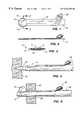
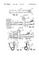
- FIG. 1is a plan of a first embodiment of the anchor, employing a balloon provided with an adhesive backing wherein a shielding strip is temporarily disposed over the backing;
- FIG. 2is an elevational view of the anchor shown in FIG. 1;
- FIG. 3is a cross-sectional view of the anchor shown in FIG. 1, taken on the plane designated by line 3 — 3 ;
- FIG. 4is an elevational view of the FIG. 1 anchor in place on a trocar sheath, with the balloon of the anchor in a deflated condition and a trocar extended through the sheath in the process of forming a puncture opening in a tissue layer;
- FIG. 5is an elevational view similar to that of FIG. 4, showing the sheath fully extended through the puncture opening, with the balloon inflated and the trocar removed from the sheath;
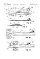
- FIG. 6is a plan view of a second embodiment of the anchor, employing a balloon of an elongate generally hourglass-shaped configuration provided with an adhesive backing wherein a shielding strip is temporarily disposed over the backing;
- FIG. 7is an elevational view of the anchor shown in FIG. 6;
- FIG. 8is an cross-sectional view of the anchor shown in FIG. 6, taken on the plane designated by line 8 — 8 ;
- FIG. 9is an elevational view of the FIG. 6 anchor in place on a trocar sheath with the balloon of the anchor in a deflated condition and a trocar extended through the sheath in the process of forming a puncture opening in a tissue layer;
- FIG. 10is an elevational view similar to FIG. 9, showing the sheath fully extended through the puncture opening, with the balloon inflated and the trocar removed from the sheath;
- FIG. 11is a plan view of a third embodiment of the anchor, employing a balloon having a securing patch disposed thereover wherein the patch is provided with an adhesive backing and a shielding strip is temporarily disposed over the backing;
- FIG. 12is an elevational view of the anchor shown in FIG. 11;
- FIG. 13is a cross-sectional view of the anchor shown in FIG. 11, taken on the plane designated by line 13 — 13 ;
- FIG. 14is an elevational view of the FIG. 11 anchor in place on a trocar sheath, with the balloon of the anchor in a deflated condition and a trocar extended through the sheath in the process of forming a puncture opening in a tissue layer;
- FIG. 15is an elevational view similar to that of FIG. 14, showing the sheath fully extended through the puncture opening, with the balloon inflated and the trocar removed from the sheath;
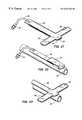
- FIG. 16is a plan view of a fourth embodiment of the anchor employing a balloon, wherein the balloon has two separately inflatable chambers and an adhesive backing with a shielding strip temporarily disposed over the backing;
- FIG. 17is an elevational view of the anchor shown in FIG. 16;
- FIG. 18is a cross-sectional view of the anchor shown in FIG. 16, taken on the plane designated by line 18 — 18 ;
- FIG. 19is an elevational view of the FIG. 16 anchor in place on a trocar sheath with the balloon of the anchor in a deflated condition and the trocar extended through the sheath in the process of forming a puncture opening in a tissue layer;
- FIG. 20is an elevational view similar to that of FIG. 19, showing the sheath fully extended through the puncture opening, with both chambers of the balloon inflated and the trocar removed from the sheath;
- FIG. 21is a perspective view of a fifth embodiment of the anchor employing a balloon with an adhesive backing, wherein the balloon is elongate and extends across the backing;
- FIG. 22is a perspective view of the anchor shown in FIG. 21 adhesively secured to a trocar sheath, with the balloon in a deflated condition folded against the sheath;
- FIG. 23is a perspective view similar to that of FIG. 22, showing the balloon inflated and extending transversely to either side of the sheath;
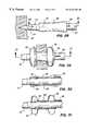
- FIG. 24is an elevational view of a sixth embodiment of the anchor in place on a trocar sheath, with the balloon of the anchor in a deflated condition and a trocar extended through the sheath in the process of forming a puncture opening in a tissue layer;
- FIG. 25is an elevational view similar to that of FIG. 24, showing the sheath fully extended through the puncture opening, with the balloon inflated and the trocar removed from the sheath;
- FIG. 26is a cross-sectional view taken on the plane designated by line 26 — 26 of FIG. 24;
- FIG. 27is a cross-sectional view taken on the plane designated by line 27 — 27 of FIG. 25;
- FIG. 28is an elevational view of a seventh embodiment of the anchor in place on a trocar sheath, with the balloon of the anchor in a deflated condition and a trocar extended through the sheath in the process of forming a puncture opening in a tissue layer;
- FIG. 29is an elevational view similar to that of FIG. 28, showing the sheath fully extended through the puncture opening, with the balloon inflated and the trocar removed from the sheath;
- FIG. 30is a cross-sectional view taken on the plane designated by line 30 — 30 of FIG. 28;
- FIG. 31is a cross-sectional view taken on the plane designated by line 31 — 31 of FIG. 29;
- FIG. 32is an elevational view of an eighth embodiment of the anchor in place on a trocar sheath with the balloon of the anchor in a deflated condition and a trocar extended through the sheath in the process of forming a puncture opening in a tissue layer;
- FIG. 33is an elevational view similar to that of FIG. 32, showing the sheath fully extended through the puncture opening, with the balloons of the anchor inflated and the trocar removed from the sheath;
- FIG. 34is a cross-sectional view taken on the plane designated by line 34 — 34 of FIG. 33;
- FIG. 35is a plan view of a flat balloon adapted to be wrapped around a trocar sheath to provide a generally angular balloon in a ninth embodiment of the anchor;
- FIG. 36is an elevational view of the ninth embodiment of the anchor in place on a trocar sheath, with the balloons of the anchor in a deflated condition and a trocar extending through the sheath in the process of forming a puncture opening in a tissue layer;
- FIG. 37is an elevational view similar to that of FIG. 36, showing the sheath fully extended through the puncture opening, with the balloons inflated and the trocar removed from the sheath;
- FIG. 38is a cross-sectional view taken on the plane designated by line 38 — 38 of the FIG. 36;
- FIG. 39is a cross-sectional view taken on the plane designated by line 39 — 39 of FIG. 37;
- FIG. 40is a plan view of a tenth embodiment of the anchor employing a distal balloon corresponding generally to that of the first embodiment and a proximal balloon connected to the distal balloon by a web;
- FIG. 41is a plan view of the tenth embodiment anchor wherein the proximal balloon has been folded over and wrapped around the air passage leading to the distal balloon;
- FIG. 42is an elevational view of the tenth embodiment anchor in place on a trocar sheath, with the balloons of the anchor in a deflated condition and a trocar extending through the sheath in the process of forming a puncture opening in a tissue layer;
- FIG. 43is an elevational view similar to that of FIG. 42, showing the sheath fully extended through the puncture opening, with the balloons inflated and the trocar removed from the sheath; and,
- FIG. 44is a cross-sectional view taken on the plane designated by line 44 — 44 of FIG. 43 .
- this embodimentcomprises an elastomeric balloon 10 having a first film layer 11 of elastic or semi-elastic material, and a second film layer 12 of elastic, semi-elastic or inelastic material.
- Second film layer 12is ideally very flexible so that it can easily confirm to the outside surface of an instrument such as a trocar sheath.
- first film layer 11 and second film layer 12are made of material suitable for medical applications having a good strength to thickness ratio. Thinner materials facilitate lower deflated profiles and thus lower incision insertion forces.
- First film layer 11can be made of urethane or other appropriate film.
- PS-8010 polyurethane filmmanufactured by Deerfield Urethane of Deerfield, Mass.
- Second film layer 12is preferably a flexible inelastic material, such as polyester.
- a suitable materialis Rexham 705517 manufactured by Rexham Industrial, Inc. of Matthews, N.C.
- first and second film layers 11 , 12can be made of the same elastic or semi-elastic material if desired.
- a contact adhesive 14is adhered to the undersurface of second layer 12 and covered by a removable paper or plastic shielding strip 16 . Contact adhesive 14 and corresponding shielding strip 16 are cut-away at portions 13 to facilitate unrestrained expansion of the balloon upon inflation.
- An inflation tube 18is integrally formed by bonding first and second film layers 11 , 12 together.
- a check valve or stop cock 20is secured to the proximal end of the tube 18 for purposes of introducing inflation fluid (liquid or gas) into the tube 18 .
- the balloon 10is formed by peripherally bonding first layer 11 and second layer 12 together thereby creating a sealed inflatable chamber 9 therebetween.
- An alternative construction for the balloonwould be to fabricate the balloon as a closed elastomeric envelope with contact adhesive applied directly one side of the envelope. With such a construction, a removable paper or plastic shielding strip would also be provided over the adhesive.
- the balloon of such a constructionwould be adhered directly to an instrument with the contact adhesive. The surface of the instrument would serve as the inelastic backing restraining the balloon from elongation upon inflation.
- FIG. 4illustrates the first embodiment balloon attached to the smooth outer surface of an instrument, in this case a conventional trocar sheath 22 .
- the shielding strip 16has been removed from the adhesive 14 and the second film layer 12 is adhered to the sheath by the adhesive.
- the balloon 10 and tube 18have a low profile essentially contiguous with the outside surface of the sheath 22 .
- FIG. 4also shows a sharp tipped trocar 24 extending through the sheath 22 and into piercing engagement with a layer of living tissue 26 such as an abdominal wall.
- the sheath 22is telescopically received on the trocar 24 and moves with the trocar through the tissue 26 .
- FIG. 5shows the sheath 22 extended fully through a puncture opening 28 which has been formed by the trocar 24 , with the trocar removed from the sheath.
- the balloon 12has been inflated to the interior of the tissue to anchor the sheath distally against removal from the puncture. With the sheath so anchored, other instruments can be passed therethrough for diagnostic or surgical purposes and withdrawn from the sheath without unwanted proximal movement of the sheath.
- the balloon 12is deflated to return to the condition shown in FIG. 4 and the sheath may be removed from the incision with a minimum of trauma.
- FIGS. 6-10This embodiment is illustrated in FIGS. 6-10 and is similar to the first embodiment, with the exception that the balloon 10 a is of an elongate hourglass-shaped configuration.
- Parts of the second embodiment corresponding to those of the first embodimentare designated by like numerals followed by the letter a, as follows: elastic balloon 10 a ; first layer 11 a; second layer 12 a; chamber 9 a; adhesive cut-away portions 13 a; contact adhesive 14 a; shielding strip 16 a; inflation tube 18 a; and check valve or stop cock 20 a.
- the second embodiment balloonis applied and used in the same way as that of the first embodiment.
- the balloonis adhered to the outside surface of a trocar sheath 22 so as to extend longitudinally of the sheath.
- the hourglass shape of the balloon 10 aprovides distal and proximal portions 30 and 32 , respectively.
- these portionsUpon extension of the sheath 22 through the tissue as shown in FIG. 10, these portions are disposed to either side of the tissue 26 to anchor the sheath 22 against movement distally into or proximally out of the opening 28 through which the sheath extends.
- the necked-down portion of the balloon 10 adesignated 34 , does not significantly expand upon inflation of the portions 30 and 32 . Constraint of the portion 34 is provided both by its reduced dimension, as compared to the portions 30 and 32 , and its adherence to the second film layer 12 a.
- the balloon 10 awhen in the deflated condition the balloon 10 a assumes a low profile configuration essentially contiguous with the outside surface of the sheath 12 . This minimizes trauma to the tissue both during insertion and removal of the sheath.
- the third embodimentis similar to that of the first embodiment, with the exception that the balloon, designated 10 b, is a closed elastomeric envelope having top and bottom surfaces; and the backing strip is a patch 36 adhered to and extending over the balloon.
- the patch 36is provided with contact adhesive 38 to either side of the balloon 10 b.
- a removable paper or plastic shielding strip 16 bextends across the balloon 10 b and over the adhesive 38 .
- Inflation tube 18 b for the third embodimentis contiguous with the balloon 10 b and also adhered beneath the patch 36 .
- Contact adhesive 38 on the patch 36is disposed to either side of the tube 18 b and covered by the removable shielding strip 16 b.
- a check valve or stop cock 20 bis secured in the proximal end of the inflation tube 18 b.
- FIG. 14shows the balloon so applied to a trocar sheath 22 having a trocar 24 extended therethrough.
- the adhesive 38 to either side of the balloon 10 b and inflation tube 18 badheres directly to the smooth outside surface of the trocar sheath 22 .
- a perforated tear line 40is formed in the patch 36 over the balloon 10 b.
- the third embodiment balloon 10 bis extended through the tissue 26 in the same manner as the first embodiment balloon. After being extended fully through the tissue as shown in FIG. 40, the balloon is inflated to the inside of the tissue. Such inflation functions to tear the patch 36 along the frangible tear line 40 . Upon completion of the surgical procedure or as otherwise desired, the balloon may be deflated to return to its condition closely contiguous to the sheath so that the sheath may be removed with a minimum of trauma.
- the third embodiment sheath shown in FIGS. 11-15is provided with a thin spacer string 42 between the inner and outer sides of the balloon 10 b.
- this stringextends over the full length of the balloon 10 b and inflation tube 18 b so as to prevent the sides of the balloon and tube from fully closing against one another when the balloon is in the deflated condition.
- the space provided by the stringprovides a fluid passage and facilitates inflation of the balloon with a minimum of pressure.
- the fourth embodimentcorresponds to the first embodiment, with the addition that it is provided with a second balloon 44 of an elongate-divergent configuration.
- the balloon 44diverges from the distal balloon, designated 10 c.
- the balloons 10 c and 44provide separate inflation chambers.
- a separate inflation tube 46 having a check valve or stop cock 48is provided for inflation of the balloon 44 .
- the elements of the fourth embodiment corresponding to those of the first embodimentare designated by like numerals, followed by the letter c, as follows: balloon 10 c; first film layer 12 c; second film layer 12 c; adhesive cut-away portions 13 c; contact adhesive 14 c; shielding strip 16 c; inflation tube 18 c; and, check valve or stop cock 20 c.
- the fourth embodiment anchoris applied to an instrument and surgically inserted in the same manner as the first embodiment anchor.
- FIG. 19wherein the fourth embodiment anchor is shown attached to the smooth outside surface of the trocar sheath 22 having a sharp tipped trocar 24 extended therethrough into piercing engagement with a layer of living tissue 26 .
- the balloon 10 cis first inflated to the interior of the tissue to anchor the sheath against removal in the proximal direction.
- the second balloon 44is then inflated to anchor the sheath against movement interiorally of the tissue in the distal direction relative to the user.
- the elongate tapered configuration of the balloon 44accommodates tissue of virtually any thickness and can also serve to form a seal between the interior of the puncture 28 and the sheath 22 .
- both balloonsare deflated and the sheath is removed, with a minimum of trauma.
- the balloon of this embodimentis of a generally T-shaped configuration and fabricated of superimposed sheets of flexible inelastic film.
- the commercially available film known as Rexham 705517has been found suitable.
- FIG. 21shows the fifth embodiment anchor in deflated condition as it would be supplied for use with any desired surgical instrument.
- the anchorcomprises a balloon 52 fabricated of superimposed peripherally connected sheets of elastic, semi-elastic or inelastic flexible film. Preferably, semi-elastic urethane material is used.
- the balloonhas an elongate transverse section 56 and a longitudinally extending section 58 .
- An inflation tube 60 having a check valve or stop cock 62is secured in fluid communication with the section 58 .
- a contact adhesive layeris secured to and extends over the section 58 .
- a removable shielding strip 66is disposed over the adhesive 64 . As shown, the adhesive 64 is adhered directly to the balloon 52 .
- the fifth embodiment anchoris adhered to the outside surface of an instrument and used in essentially the same manner as the first embodiment anchor.
- FIG. 22shows the anchor secured to a trocar sheath 22 .
- the shielding strip 66has been removed from the adhesive and the section 58 has been adhered longitudinally of the sheath with the adhesive 64 .
- FIG. 22shows the ends of the transverse balloon section 56 folded over the section 58 , it should be understood that these ends are not adhered to the sheath.
- the folded over conditionis simply for purposes of reducing the profile of the balloon during insertion.
- FIG. 23shows the balloon as it would appear after inserted into place through a puncture and inflated. Such insertion would be carried out in essentially the same manner shown in FIGS. 4 and 5.
- inflation of the anchorfunctions to expand the transverse section transversely of the trocar sheath 22 , thus securely anchoring the sheath against removal from the puncture opening.
- the balloonis deflated and may collapse against the sheath upon removal, with a minimum of trauma.
- the sixth embodiment anchoris of an elongate toroidal configuration and adapted to be slipped over and around a surgical instrument, without need for an adhesive.
- this embodimentcomprises: an elongate toroidal elastic balloon 68 ; spaced proximal and distal rings 70 and 72 , respectively, disposed within the balloon 68 ; an intermediate ring 74 disposed around the balloon between the proximal and distal rings; and, an inflation tube 76 communicating with the interior of the balloon through a flange 78 on the ring 70 .
- the balloon 68is fabricated of a sleeve folded over upon itself with one end of the sleeve tied to the ring 72 by a cord 80 and the other end of the sleeve tied to the outside of the flange 78 by a cord 82 .
- the sixth embodiment anchoris simply slipped over the instrument to which it is applied.
- the instrumentcomprises a trocar sheath 22 .
- the balloonis deflated and a sharp tipped trocar 24 extends through the sheath 22 into piercing engagement with a layer of living tissue 26 .
- the balloon 68is inflated as shown in FIG. 25 to expand to either side of the tissue.
- the balloonforms donut-shaped barriers to either side of the tissue. Expansion of the balloon within the thickness of the tissue is prevented by the ring 74 .
- the space between the rings 72 and 70permits the interior wall of the balloon to expand into gripping engagement with the sheath, as shown in FIG. 27 .
- the sheathis anchored against movement into or out of the pierced tissue.
- the balloonis deflated and returns to the condition shown in FIG. 26, thus permitting removal of the anchor with a minimum of trauma.
- one or more thin ribsmay be provided between the proximal and distal rings 70 and 72 . These ribs (not illustrated) are so proportioned and spaced so as not to interfere with inward expansion of the balloon into gripping engagement with the sheath, as shown in FIG. 27 .
- the outer intermediate ring 74may be adhered to the outside surface of the balloon 68 to prevent its displacement along the balloon.
- the seventh embodiment anchoris similar to that of the sixth embodiment in that it employs an elongate toroidal balloon adapted to be received around the instrument to be anchored.
- the balloonis preferably fabricated so that the distal portion of the balloon is elastomeric and the proximal portion is inelastic.
- FIG. 30shows such a construction wherein an inner elastomeric sleeve 84 is folded upon itself to provide a distal balloon section 86 .
- An inelastic sleeve 88is extended over the sleeve 84 .
- the inelastic sleeve 84is circumferentially welded to the folded over end of the inner sleeve 84 at a weld line 90 . From the weld line to the distal end of the inelastic sleeve a perforated tear line 92 is provided to permit the sleeve to break upon expansion of the distal balloon section 86 .
- the proximal end of the outer inelastic sleeve 88is folded upon itself and circumferentially sealed to a flange member 94 by a tie.
- An inflation tube 96extends through the flange member 94 into fluid communication with the interior of the balloon formed by the sleeves 84 and 88 .
- the seventh embodiment anchoris slipped around the instrument to be anchored.
- the instrumentcomprises a trocar sheath 22 having a sharp tipped trocar 24 extending therethrough in the process of piercing an opening in a layer of living tissue 26 .
- the trocaris pushed fully through the tissue, together with the anchor.
- the trocaris removed and the balloon is inflated.
- Inflationfunctions to form toroidal balloon sections to either side of the tissue and to interiorally expand the balloon into gripping engagement with the sheath.
- the sheathis anchored against movement into or out of the tissue.
- the inelastic sleevetears along the tear line 92 . That portion of the sleeve 88 within the tissue remains intact and functions to constrain the balloon.
- the proximal end of the balloondesignated 98 , expands to a toroidal configuration by unfolding the folded over portions of the sleeve 88 (see FIG. 30 ).
- the balloonis deflated, thus permitting the anchor to be removed with a minimum of trauma.
- FIGS. 32-34This embodiment is illustrated in FIGS. 32-34 and corresponds to the first embodiment, with the addition that it is provided with a toroidal balloon assembly 100 adapted to be slidably received around the balloon 10 and its air passage 18 .
- Elements of the eighth embodiment corresponding to those of the first embodimentare designated by like numerals.
- the purpose of the torodial balloon assembly 100is to provide an anchor “ring” which can be freely moved along a trocar sheath or other instrument to which the balloon 10 is adhered to provide a skin-side anchor which may be adjusted to accommodate the thickness of the tissue (e.g., abdominal wall) through which the sheath is extended.
- the balloon assemblyis in a deflated condition and freely movable along the sheath.
- the assemblyUpon being adjusted to the desired position (see FIG. 33 ), the assembly is inflated, thus causing its inner diameter to decrease into secure gripping engagement with the sheath.
- the balloon assembly 100is fabricated with an elastic or semi-elastic inner film layer 102 and an elastic or semi-elastic outer film layer 104 which are peripherally RF welded together.
- the materials for these layersmay be the same as those suggested for the balloon of the first embodiment.
- a check valve or stop cock 20is sealingly secured in the open end of the balloon assembly 100 .
- the inner construction of the toroidal balloon assembly 100is illustrated in FIG. 34 . As there seen, the assembly is elongate and wrapped upon itself to form a toroidal configuration. The proximal and distal ends of the elongate balloon are adhered or welded together at area 106 . The trocar sheath 22 is shown slidably received within the toroid provided by the assembly.
- the balloon 10would be secured to the sheath in a manner identical to that described with respect to the first embodiment.
- the toroidal balloon assembly 100would then be slid over the sheath in a deflated condition. Then the sheath would be passed through the tissue 26 and anchored against removal by inflation of the balloon 10 , as shown in FIG. 29 .
- the deflated toroidal assembly 100would then be adjusted along is the length of the sheath to engage the outside of the tissue and then inflated, as shown in FIG. 33 .
- the latter inflationfunctions to expand the assembly 100 into gripping engagement with the sheath and anchor the sheath against movement distally relative to the tissue.
- FIGS. 35-39This embodiment is shown in FIGS. 35-39 and is similar to the eighth embodiment in that it is used with the distal balloon 10 of the first embodiment and provides a skin-side anchor. It differs from the eighth embodiment only in the construction of the skin-side anchor assembly, designated 108 . Elements of the ninth embodiment corresponding to those of the first embodiment are designated by like numerals.
- the anchor assembly 108is similar to the assembly 100 in that it is fabricated of an elastic or semi-elastic inner film layer 110 and an inelastic or semi-elastic outer film layer 112 peripherally RF welded together to provide a balloon.
- a weld line 114is formed to extend across the assembly intermediate its length so that the balloon only extends over approximately one-half of the length of the assembly (see FIG. 35 ).
- the distal and proximal ends of the assemblyare not welded together, but rather are provided with contact adhesive 14 whereby they may be selectively secured together after being wrapped around an instrument.
- a check valve or stock cock 20is sealingly received in the open end of the balloon provided by the assembly 108 .
- FIGS. 38 and 39show how the assembly 108 is placed around the trocar sheath 22 .
- the assemblyis being wrapped around the sheath.
- the distal and proximal ends of the assemblyhave been secured together by the adhesive 14 and the balloon has been inflated to expand the assembly into gripping engagement with the sheath.
- the ninth embodiment anchoris passed through a tissue layer in the same manner as the first embodiment anchor and the distal balloon 10 is then inflated, as seen in FIG. 37 . Then the assembly 108 is slid along the sheath 22 into engagement with the outside surface of the tissue. Once so engaged, the assembly is inflated to securely engage the assembly with the outside surface of the sheath and anchor the sheath against distal movement relative to the tissue.
- FIG. 36shows the assembly 108 in place around the sheath prior to extension of the sheath through the tissue layer 26 .
- the assemblycould be wrapped around the sheath after it has been extended through the tissue. Such a procedure is possible because the assembly is capable of being wrapped around the sheath after it is in place within a layer of body tissue.
- FIGS. 40-44This embodiment is shown in FIGS. 40-44 and also incorporates the distal balloon of the first embodiment.
- a skin-side anchor assembly 116is connected in transverse relationship to the inflation tube 18 by a flexible web 118 .
- Elements of the tenth embodiment corresponding to those of the first embodimentare designated by like numerals.
- the assembly 116 and web 118are fabricated from continuations of the film layers forming the balloon 10 and the tube 18 . These layers are peripherally welded together at a weld line 120 extending around the assembly 116 . One end of the assembly 116 is open and sealingly receives a check valve or stock cock 20 . An aperture 122 proportioned for receipt over the distal end of the valve 20 is formed in the end of the assembly 116 opposite that which receives the valve.
- the web 118is folded over the tube 18 to dispose the first elastic film layer 11 of the assembly in opposition to the tube 18 . Then the assembly is wrapped around the inflation tube 118 to engage the aperture 122 over the distal end of the valve 20 , as shown in FIG. 41 .
- the generally toroidal balloon provided by the anchormay be slipped over an instrument, such as a trocar sheath, with which it is used. Initially, the shielding strip 16 would be left in place as the anchor is so positioned. Once the balloon 10 is positioned as desired, its distal end would be lifted and the shielding strip would be removed. Then the balloon 10 and the inflation tube 18 would be pressed into secure adhered relationship with the outside of the instrument, as shown in FIG. 42 .
- the sheathWith the tenth embodiment anchor in place on a trocar sheath as shown in FIG. 42 and the balloons in deflated condition, the sheath is initially passed through a tissue layer and anchored with the distal balloon 10 in same manner as the first embodiment. Once so in place, the assembly 116 is slid along the sheath into engagement with the outside of the tissue, as shown in FIG. 43, and inflated. The flexibility of the web 118 facilitates such adjustment. Inflation of the assembly 116 serves to secure the assembly against movement relative to the sheath and anchor the sheath against distal movement.
- the present inventionenables the attainment of the objects initially set forth herein.
- itprovides an anchor which may be readily applied to any surgical instrument without modification of the instrument and which may be used with a minimum of trauma to the patient. While all embodiments serve as effective anchors, the tenth embodiment is considered the preferred embodiment because of its ease of manufacture from two layers of film material and the secure anchor which it provides against both proximal and distal movement. It should be understood, however, that the invention is not intended to be limited to the specifics of the illustrated embodiments, but rather is defined by the accompanying claims.
Landscapes
- Health & Medical Sciences (AREA)
- Life Sciences & Earth Sciences (AREA)
- Public Health (AREA)
- General Health & Medical Sciences (AREA)
- Veterinary Medicine (AREA)
- Engineering & Computer Science (AREA)
- Biomedical Technology (AREA)
- Heart & Thoracic Surgery (AREA)
- Surgery (AREA)
- Animal Behavior & Ethology (AREA)
- Molecular Biology (AREA)
- Medical Informatics (AREA)
- Pathology (AREA)
- Nuclear Medicine, Radiotherapy & Molecular Imaging (AREA)
- Biophysics (AREA)
- Pulmonology (AREA)
- Anesthesiology (AREA)
- Hematology (AREA)
- Surgical Instruments (AREA)
Abstract
Description
Claims (34)
Priority Applications (3)
| Application Number | Priority Date | Filing Date | Title |
|---|---|---|---|
| US08/447,794US6524283B1 (en) | 1994-10-07 | 1995-05-23 | Method and apparatus for anchoring laparoscopic instruments |
| US10/373,487US7235064B2 (en) | 1994-10-07 | 2003-02-25 | Method and apparatus for anchoring laparoscopic instruments |
| US11/804,130US20070225643A1 (en) | 1994-10-07 | 2007-05-17 | Method and apparatus for anchoring laparoscopic instruments |
Applications Claiming Priority (2)
| Application Number | Priority Date | Filing Date | Title |
|---|---|---|---|
| US08/320,042US5697946A (en) | 1994-10-07 | 1994-10-07 | Method and apparatus for anchoring laparoscopic instruments |
| US08/447,794US6524283B1 (en) | 1994-10-07 | 1995-05-23 | Method and apparatus for anchoring laparoscopic instruments |
Related Parent Applications (1)
| Application Number | Title | Priority Date | Filing Date |
|---|---|---|---|
| US08/320,042DivisionUS5697946A (en) | 1994-10-07 | 1994-10-07 | Method and apparatus for anchoring laparoscopic instruments |
Related Child Applications (1)
| Application Number | Title | Priority Date | Filing Date |
|---|---|---|---|
| US10/373,487ContinuationUS7235064B2 (en) | 1994-10-07 | 2003-02-25 | Method and apparatus for anchoring laparoscopic instruments |
Publications (1)
| Publication Number | Publication Date |
|---|---|
| US6524283B1true US6524283B1 (en) | 2003-02-25 |
Family
ID=23244626
Family Applications (4)
| Application Number | Title | Priority Date | Filing Date |
|---|---|---|---|
| US08/320,042Expired - LifetimeUS5697946A (en) | 1994-10-07 | 1994-10-07 | Method and apparatus for anchoring laparoscopic instruments |
| US08/447,794Expired - LifetimeUS6524283B1 (en) | 1994-10-07 | 1995-05-23 | Method and apparatus for anchoring laparoscopic instruments |
| US10/373,487Expired - Fee RelatedUS7235064B2 (en) | 1994-10-07 | 2003-02-25 | Method and apparatus for anchoring laparoscopic instruments |
| US11/804,130AbandonedUS20070225643A1 (en) | 1994-10-07 | 2007-05-17 | Method and apparatus for anchoring laparoscopic instruments |
Family Applications Before (1)
| Application Number | Title | Priority Date | Filing Date |
|---|---|---|---|
| US08/320,042Expired - LifetimeUS5697946A (en) | 1994-10-07 | 1994-10-07 | Method and apparatus for anchoring laparoscopic instruments |
Family Applications After (2)
| Application Number | Title | Priority Date | Filing Date |
|---|---|---|---|
| US10/373,487Expired - Fee RelatedUS7235064B2 (en) | 1994-10-07 | 2003-02-25 | Method and apparatus for anchoring laparoscopic instruments |
| US11/804,130AbandonedUS20070225643A1 (en) | 1994-10-07 | 2007-05-17 | Method and apparatus for anchoring laparoscopic instruments |
Country Status (1)
| Country | Link |
|---|---|
| US (4) | US5697946A (en) |
Cited By (78)
| Publication number | Priority date | Publication date | Assignee | Title |
|---|---|---|---|---|
| US20030139758A1 (en)* | 1994-10-07 | 2003-07-24 | Hopper Phillip K. | Method and apparatus for anchoring laparoscopic instruments |
| US20030236544A1 (en)* | 1991-05-29 | 2003-12-25 | Lunsford John P. | Method and inflatable chamber apparatus for separating layers of tissue |
| US20040106900A1 (en)* | 2002-11-30 | 2004-06-03 | Triebes Thomas Gregory | Catheter with unitary component |
| US20040106901A1 (en)* | 2002-11-30 | 2004-06-03 | Letson William W. | Catheter having a balloon member invertedly attached thereto |
| US20040103518A1 (en)* | 2002-11-30 | 2004-06-03 | Triebes Thomas Gregory | Process for securing a tip member to a catheter during production of the tip member |
| US20040106899A1 (en)* | 2002-11-30 | 2004-06-03 | Mcmichael Donald J. | Gastric balloon catheter with improved balloon orientation |
| US20040138702A1 (en)* | 2001-05-31 | 2004-07-15 | Kenneth Peartree | Balloon cannula with over-center clamp |
| US20050038381A1 (en)* | 2003-08-11 | 2005-02-17 | Kimberly-Clark Worldwide, Inc. | Catheter having a balloon member recessedly attached thereto |
| US20050107803A1 (en)* | 2003-11-14 | 2005-05-19 | Guanche Carlos A. | Cannula delivery and support system |
| US20050165378A1 (en)* | 2002-04-16 | 2005-07-28 | Russell Heinrich | Method and apparatus for anastomosis including an expandable anchor |
| US20050165432A1 (en)* | 2002-05-09 | 2005-07-28 | Russell Heinrich | Adjustable balloon anchoring trocar |
| US20050165449A1 (en)* | 2003-12-02 | 2005-07-28 | Board Of Regents, The University Of Texas System | Surgical anchor and system |
| US20050228445A1 (en)* | 1995-05-19 | 2005-10-13 | Mollenauer Kenneth H | Skin seal with inflatable membrane |
| WO2006031934A3 (en)* | 2004-09-15 | 2006-05-26 | Light Sciences Corp | Surgical sheath with instrument fixation structures |
| US20060167482A1 (en)* | 2003-04-04 | 2006-07-27 | Swain Christopher P | Device for transfixing and joining tissue |
| US20070106522A1 (en)* | 2005-11-08 | 2007-05-10 | Bruce Collins | System for distributing packages and channels to a device |
| US20070213675A1 (en)* | 2006-03-13 | 2007-09-13 | Applied Medical Resources Corporation | Balloon trocar |
| US20070225650A1 (en)* | 2006-03-21 | 2007-09-27 | Applied Medical Resources Corporation | Cannula stabilization seal |
| US20070239108A1 (en)* | 2006-03-13 | 2007-10-11 | Applied Medical Resources Corporation | Balloon trocar |
| US20070255273A1 (en)* | 2006-04-29 | 2007-11-01 | Board Of Regents, The University Of Texas System | Devices for use in Transluminal and Endoluminal Surgery |
| US20090043314A1 (en)* | 2007-07-16 | 2009-02-12 | The Cleveland Clinic Foundation | Access device for body tissue and method of using same |
| US20090105659A1 (en)* | 2007-10-17 | 2009-04-23 | Tyco Healthcare Group Lp | Anchoring cannula |
| US20090264913A1 (en)* | 2008-04-21 | 2009-10-22 | Applied Medical Resources Corporation | Tamponade trocar device and method |
| US20090287045A1 (en)* | 2008-05-15 | 2009-11-19 | Vladimir Mitelberg | Access Systems and Methods of Intra-Abdominal Surgery |
| US20100198257A1 (en)* | 2006-09-06 | 2010-08-05 | Joshua Stopek | Bioactive Substance in a Barbed Suture |
| US20100204729A1 (en)* | 2008-09-11 | 2010-08-12 | Ahmad Robert Hadba | Tapered Looped Suture |
| US20100204730A1 (en)* | 2008-10-09 | 2010-08-12 | Nicholas Maiorino | Knotted Suture End Effector |
| US20100211097A1 (en)* | 2008-02-20 | 2010-08-19 | Ahmad Robert Hadba | Compound Barb Medical Device and Method |
| US20100211098A1 (en)* | 2008-02-20 | 2010-08-19 | Ahmad Robert Hadba | Compound Barb Medical Device and Method |
| US20100274095A1 (en)* | 2009-02-24 | 2010-10-28 | The Hospital For Special Surgery | Expanding cannula and retractor device and methods of use |
| US20110009704A1 (en)* | 2009-07-08 | 2011-01-13 | Stanislaw Marczyk | Apparatus and Method for Transvaginal Surgery |
| US20110087224A1 (en)* | 2009-10-09 | 2011-04-14 | Cadeddu Jeffrey A | Magnetic surgical sled with variable arm |
| US20110196205A1 (en)* | 2010-02-05 | 2011-08-11 | Tyco Healthcare Group Lp | Surgical portal locking system |
| WO2011093635A3 (en)* | 2010-01-29 | 2012-01-05 | 연세대학교 산학협력단 | Balloon catheter and a blood-vessel expanding device using the same |
| US8157833B2 (en) | 2005-11-09 | 2012-04-17 | Applied Medical Resources Corporation | Trocars with advanced fixation |
| US8206291B2 (en) | 2009-03-27 | 2012-06-26 | Tyco Healthcare Group Lp | Portal device |
| US20120245510A1 (en)* | 2011-03-22 | 2012-09-27 | Rakower Stephen R | Adhesiolysis system |
| US8753267B2 (en) | 2011-01-24 | 2014-06-17 | Covidien Lp | Access assembly insertion device |
| USD712034S1 (en) | 2007-10-05 | 2014-08-26 | Covidien Lp | Seal anchor for use in surgical procedures |
| US8888692B1 (en) | 2011-08-26 | 2014-11-18 | Applied Medical Resources Corporation | Trocar cannula assembly and method of manufacture |
| KR20150000447A (en)* | 2011-08-17 | 2015-01-02 | 존 스티븐 파카크 | Trocar support |
| USD738500S1 (en) | 2008-10-02 | 2015-09-08 | Covidien Lp | Seal anchor for use in surgical procedures |
| US9271752B2 (en) | 2013-03-13 | 2016-03-01 | Swan Valley Medical Incorporated | Method and apparatus for placing a cannula in a bladder |
| WO2016049560A1 (en)* | 2014-09-26 | 2016-03-31 | Vanderbilt University | Movement dampening system for a surgical tool |
| US9522265B2 (en) | 2013-03-15 | 2016-12-20 | Applied Medical Resources Corporation | Trocar cannula assembly with low profile insertion configuration and method of manufacture |
| US9554788B1 (en)* | 2005-08-12 | 2017-01-31 | Michael R. Redler | Methods and apparatus for performing arthroscopic surgery |
| US9707011B2 (en) | 2014-11-12 | 2017-07-18 | Covidien Lp | Attachments for use with a surgical access device |
| US10064649B2 (en) | 2014-07-07 | 2018-09-04 | Covidien Lp | Pleated seal for surgical hand or instrument access |
| US10327809B2 (en) | 2016-02-29 | 2019-06-25 | Covidien Lp | Clip collar advanced fixation |
| US10675056B2 (en) | 2017-09-07 | 2020-06-09 | Covidien Lp | Access apparatus with integrated fluid connector and control valve |
| US10792071B2 (en) | 2019-02-11 | 2020-10-06 | Covidien Lp | Seals for surgical access assemblies |
| US10828065B2 (en) | 2017-08-28 | 2020-11-10 | Covidien Lp | Surgical access system |
| US10988371B2 (en) | 2017-05-10 | 2021-04-27 | Stephen Nicholas Logsdon | Methods of manufacturing medical pads |
| US11000313B2 (en) | 2019-04-25 | 2021-05-11 | Covidien Lp | Seals for surgical access devices |
| US11051845B2 (en)* | 2017-01-14 | 2021-07-06 | Choon Kee Lee | Non-surgical chest tube introducer |
| US11160682B2 (en) | 2017-06-19 | 2021-11-02 | Covidien Lp | Method and apparatus for accessing matter disposed within an internal body vessel |
| US11166748B2 (en) | 2019-02-11 | 2021-11-09 | Covidien Lp | Seal assemblies for surgical access assemblies |
| US11259840B2 (en) | 2019-06-21 | 2022-03-01 | Covidien Lp | Valve assemblies for surgical access assemblies |
| US11259841B2 (en) | 2019-06-21 | 2022-03-01 | Covidien Lp | Seal assemblies for surgical access assemblies |
| US11357542B2 (en) | 2019-06-21 | 2022-06-14 | Covidien Lp | Valve assembly and retainer for surgical access assembly |
| US11389193B2 (en) | 2018-10-02 | 2022-07-19 | Covidien Lp | Surgical access device with fascial closure system |
| US11399865B2 (en) | 2019-08-02 | 2022-08-02 | Covidien Lp | Seal assemblies for surgical access assemblies |
| US11413068B2 (en) | 2019-05-09 | 2022-08-16 | Covidien Lp | Seal assemblies for surgical access assemblies |
| US11413065B2 (en) | 2019-06-28 | 2022-08-16 | Covidien Lp | Seal assemblies for surgical access assemblies |
| US11432843B2 (en) | 2019-09-09 | 2022-09-06 | Covidien Lp | Centering mechanisms for a surgical access assembly |
| US11446058B2 (en) | 2020-03-27 | 2022-09-20 | Covidien Lp | Fixture device for folding a seal member |
| US11457949B2 (en) | 2018-10-12 | 2022-10-04 | Covidien Lp | Surgical access device and seal guard for use therewith |
| US11464540B2 (en) | 2020-01-17 | 2022-10-11 | Covidien Lp | Surgical access device with fixation mechanism |
| US11523842B2 (en) | 2019-09-09 | 2022-12-13 | Covidien Lp | Reusable surgical port with disposable seal assembly |
| US11541218B2 (en) | 2020-03-20 | 2023-01-03 | Covidien Lp | Seal assembly for a surgical access assembly and method of manufacturing the same |
| US11576701B2 (en) | 2020-03-05 | 2023-02-14 | Covidien Lp | Surgical access assembly having a pump |
| US11622790B2 (en) | 2020-05-21 | 2023-04-11 | Covidien Lp | Obturators for surgical access assemblies and methods of assembly thereof |
| US11642153B2 (en) | 2020-03-19 | 2023-05-09 | Covidien Lp | Instrument seal for surgical access assembly |
| US11717321B2 (en) | 2020-04-24 | 2023-08-08 | Covidien Lp | Access assembly with retention mechanism |
| US11751908B2 (en) | 2020-06-19 | 2023-09-12 | Covidien Lp | Seal assembly for surgical access assemblies |
| US11812991B2 (en) | 2019-10-18 | 2023-11-14 | Covidien Lp | Seal assemblies for surgical access assemblies |
| US12324606B2 (en) | 2020-01-28 | 2025-06-10 | Covidien Lp | Seal assemblies for surgical access assemblies |
| US12408944B2 (en) | 2021-01-11 | 2025-09-09 | Covidien Lp | Cannula assembly including a suction cup seal |
Families Citing this family (86)
| Publication number | Priority date | Publication date | Assignee | Title |
|---|---|---|---|---|
| US6033407A (en)* | 1998-01-27 | 2000-03-07 | Behrens; Alfred F. | Apparatus and method for intramedullary nailing and intramedullary nail therefor |
| US6659105B2 (en)* | 1998-02-26 | 2003-12-09 | Senorx, Inc. | Tissue specimen isolating and damaging device and method |
| US6540693B2 (en) | 1998-03-03 | 2003-04-01 | Senorx, Inc. | Methods and apparatus for securing medical instruments to desired locations in a patients body |
| US6056766A (en)* | 1998-06-09 | 2000-05-02 | Thompson; Ronald J. | Stabilized trocar, and method of using same |
| US6860892B1 (en)* | 1999-05-28 | 2005-03-01 | General Surgical Innovations, Inc. | Specially shaped balloon device for use in surgery and method of use |
| DE10022861C2 (en)* | 2000-05-10 | 2002-04-04 | Wolf Gmbh Richard | Guide rod for tubular shaft instruments to be inserted into a body cavity |
| US6811546B1 (en)* | 2000-08-25 | 2004-11-02 | Origin Medsystems, Inc. | Endoscopic surgical access port and method |
| US7041055B2 (en) | 2002-10-07 | 2006-05-09 | Mark LoGuidice | Instruments and methods for use in laparoscopic surgery |
| AU2003215196A1 (en) | 2002-02-15 | 2003-09-09 | Taut, Inc. | Anchoring assembly for a medical instrument |
| US7331933B2 (en)* | 2002-12-31 | 2008-02-19 | Advanced Cardiovascular Systems, Inc. | Balloon catheter with a compression member for balloon bonding |
| CA2522617C (en) | 2003-04-25 | 2012-04-17 | Tyco Healthcare Group Lp | Surgical access apparatus |
| US8105231B2 (en)* | 2003-10-31 | 2012-01-31 | Olympus Corporation | Living-body tissue removing apparatus |
| US7662164B2 (en)* | 2003-10-31 | 2010-02-16 | Olympus Corporation | Living-body tissue removing apparatus |
| US20050149094A1 (en)* | 2003-10-31 | 2005-07-07 | Olympus Corporation | Trocar |
| EP1750589A2 (en)* | 2004-05-13 | 2007-02-14 | Medtronic, Inc. | Percutaneous vein harvester |
| WO2006007410A2 (en) | 2004-06-16 | 2006-01-19 | Medtronic, Inc. | Minimally invasive coring vein harvester |
| US20060079838A1 (en)* | 2004-10-08 | 2006-04-13 | Walker Steven C | Movable Balloon anchor for medical devices |
| US20060079845A1 (en)* | 2004-10-08 | 2006-04-13 | Eben Howard And Pamela A. Howard | Movable inflatable anchor for medical devices |
| US7654979B2 (en)* | 2004-12-21 | 2010-02-02 | Advanced Cardiovascular System, Inc. | Balloon catheter having improved balloon seal |
| US20080015569A1 (en) | 2005-02-02 | 2008-01-17 | Voyage Medical, Inc. | Methods and apparatus for treatment of atrial fibrillation |
| US9345604B2 (en)* | 2005-05-02 | 2016-05-24 | Almuhannad Alfrhan | Percutaneous intragastric balloon device and method |
| US20070060884A1 (en)* | 2005-09-13 | 2007-03-15 | The Cleveland Clinic Foundation | Apparatus for insertion between a medical tube and a body tissue opening |
| US20070167967A1 (en)* | 2006-01-13 | 2007-07-19 | Olympus Medical Systems Corp. | Medical procedure via natural orifice and puncture device |
| US7998128B2 (en)* | 2006-05-15 | 2011-08-16 | Therataxis, LLC. | Active delivery and flow redirection: novel devices and method of delivery of materials to patients |
| US9055906B2 (en) | 2006-06-14 | 2015-06-16 | Intuitive Surgical Operations, Inc. | In-vivo visualization systems |
| WO2008048575A2 (en)* | 2006-10-16 | 2008-04-24 | Medtronic, Inc. | Vessel support device and method of vessel harvesting |
| US9226648B2 (en)* | 2006-12-21 | 2016-01-05 | Intuitive Surgical Operations, Inc. | Off-axis visualization systems |
| US8095213B1 (en)* | 2007-05-31 | 2012-01-10 | Purdue Pharma L.P. | Transdermal patch |
| US7853320B1 (en) | 2007-05-31 | 2010-12-14 | Purdue Pharma L.P. | Transdermal device having mechanical assist for porator-to-skin contact |
| US8047399B1 (en) | 2007-07-05 | 2011-11-01 | Purdue Pharma L.P. | Dispenser for transdermal devices |
| WO2009045265A1 (en)* | 2007-10-05 | 2009-04-09 | Maquet Cardiovascular, Llc | Devices and methods for minimally-invasive surgical procedures |
| US20090204081A1 (en)* | 2008-02-13 | 2009-08-13 | Depuy Mitek, Inc. | Compression expanded cannula |
| AU2009222028A1 (en)* | 2008-03-03 | 2009-09-11 | Applied Medical Resources Corporation | Balloon trocar advanced fixation |
| CN103961049B (en)* | 2008-03-31 | 2017-04-12 | 智能医疗系统有限公司 | Assemblies for use with an endoscope |
| US7998113B2 (en)* | 2008-09-30 | 2011-08-16 | Tyco Healthcare Group Lp | Medical device having prefilled balloon |
| US20100160947A1 (en)* | 2008-12-18 | 2010-06-24 | IMDS, Inc. | Systems and methods for dilation and dissection of tissues |
| US8992558B2 (en)* | 2008-12-18 | 2015-03-31 | Osteomed, Llc | Lateral access system for the lumbar spine |
| US10172669B2 (en) | 2009-10-09 | 2019-01-08 | Ethicon Llc | Surgical instrument comprising an energy trigger lockout |
| US8353873B2 (en)* | 2009-12-11 | 2013-01-15 | Ethicon Endo-Surgery, Inc. | Methods and devices for providing access through tissue to a surgical site |
| US8517932B2 (en)* | 2009-12-11 | 2013-08-27 | Ethicon Endo-Surgery, Inc. | Methods and devices for providing access through tissue to a surgical site |
| US8460186B2 (en)* | 2009-12-11 | 2013-06-11 | Ethicon Endo-Surgery, Inc. | Methods and devices for providing access through tissue to a surgical site |
| US8444557B2 (en)* | 2009-12-11 | 2013-05-21 | Ethicon Endo-Surgery, Inc. | Methods and devices for providing access through tissue to a surgical site |
| US8500633B2 (en)* | 2009-12-11 | 2013-08-06 | Ethicon Endo-Surgery, Inc. | Methods and devices for providing surgical access through tissue to a surgical site |
| US8926508B2 (en)* | 2009-12-17 | 2015-01-06 | Covidien Lp | Access assembly with dual anchor and seal capabilities |
| KR101142569B1 (en)* | 2010-01-29 | 2012-05-08 | 국립암센터 | Trocar apparatus |
| US8728162B2 (en) | 2010-04-15 | 2014-05-20 | Osteomed, Llc | Direct lateral spine system instruments, implants and associated methods |
| GB2480498A (en) | 2010-05-21 | 2011-11-23 | Ethicon Endo Surgery Inc | Medical device comprising RF circuitry |
| US9333025B2 (en) | 2011-10-24 | 2016-05-10 | Ethicon Endo-Surgery, Llc | Battery initialization clip |
| US9402612B2 (en)* | 2013-03-14 | 2016-08-02 | Precient Surgical, Inc. | Methods and devices for the prevention of incisional surgical site infections |
| WO2015116003A1 (en)* | 2014-01-30 | 2015-08-06 | Singapore Health Services Pte Ltd | Arterial cannula which allows proximal and distal perfusion within a cannulated vessel |
| US10159524B2 (en) | 2014-12-22 | 2018-12-25 | Ethicon Llc | High power battery powered RF amplifier topology |
| US10314638B2 (en) | 2015-04-07 | 2019-06-11 | Ethicon Llc | Articulating radio frequency (RF) tissue seal with articulating state sensing |
| US10959771B2 (en) | 2015-10-16 | 2021-03-30 | Ethicon Llc | Suction and irrigation sealing grasper |
| JP7093917B2 (en) | 2015-11-17 | 2022-07-01 | サージカル スタビライゼーション テクノロジーズ インク. | Trocar support |
| US10959806B2 (en) | 2015-12-30 | 2021-03-30 | Ethicon Llc | Energized medical device with reusable handle |
| US10856934B2 (en) | 2016-04-29 | 2020-12-08 | Ethicon Llc | Electrosurgical instrument with electrically conductive gap setting and tissue engaging members |
| US10987156B2 (en) | 2016-04-29 | 2021-04-27 | Ethicon Llc | Electrosurgical instrument with electrically conductive gap setting member and electrically insulative tissue engaging members |
| WO2018039228A1 (en) | 2016-08-23 | 2018-03-01 | Stryker European Holdings I, Llc | Instrumentation for the implantation of spinal implants |
| US10751117B2 (en) | 2016-09-23 | 2020-08-25 | Ethicon Llc | Electrosurgical instrument with fluid diverter |
| US11033325B2 (en) | 2017-02-16 | 2021-06-15 | Cilag Gmbh International | Electrosurgical instrument with telescoping suction port and debris cleaner |
| CN106963456A (en)* | 2017-03-08 | 2017-07-21 | 施爱德(厦门)医疗器材有限公司 | Puncture outfit with fixed structure |
| US10799284B2 (en) | 2017-03-15 | 2020-10-13 | Ethicon Llc | Electrosurgical instrument with textured jaws |
| US11497546B2 (en) | 2017-03-31 | 2022-11-15 | Cilag Gmbh International | Area ratios of patterned coatings on RF electrodes to reduce sticking |
| US10603117B2 (en) | 2017-06-28 | 2020-03-31 | Ethicon Llc | Articulation state detection mechanisms |
| US11484358B2 (en) | 2017-09-29 | 2022-11-01 | Cilag Gmbh International | Flexible electrosurgical instrument |
| US11033323B2 (en) | 2017-09-29 | 2021-06-15 | Cilag Gmbh International | Systems and methods for managing fluid and suction in electrosurgical systems |
| US11490951B2 (en) | 2017-09-29 | 2022-11-08 | Cilag Gmbh International | Saline contact with electrodes |
| WO2019094502A1 (en) | 2017-11-07 | 2019-05-16 | Prescient Surgical, Inc. | Methods and apparatus for prevention of surgical site infection |
| US11251635B2 (en) | 2017-12-19 | 2022-02-15 | Welch Allyn, Inc. | Vital signs monitor with a removable and dischargable battery |
| US10709475B2 (en)* | 2018-03-07 | 2020-07-14 | Edward J. Mikol | Pumping surgical cannula |
| US11202654B2 (en)* | 2018-03-07 | 2021-12-21 | Edward J. Mikol | Surgical cannula |
| EP3545857B1 (en) | 2018-03-30 | 2024-01-03 | Stryker European Operations Holdings LLC | Lateral access retractor and core insertion |
| US11564674B2 (en) | 2019-11-27 | 2023-01-31 | K2M, Inc. | Lateral access system and method of use |
| US11617857B2 (en)* | 2020-01-30 | 2023-04-04 | Medtronic Vascular, Inc. | Endovascular catheter with internal balloon |
| US20210267630A1 (en) | 2020-02-27 | 2021-09-02 | Covidien Lp | Access assembly with retention mechanism |
| US11633211B2 (en) | 2020-05-01 | 2023-04-25 | Cilag Gmbh International | Pinch to release cannula depth limiter |
| US11980392B2 (en) | 2020-05-01 | 2024-05-14 | Cilag Gmbh International | Pinch-to-clamp cannula depth limiter |
| US11986215B2 (en) | 2020-05-01 | 2024-05-21 | Cilag Gmbh International | Universal size multi-walled elastomer cannula depth limiter |
| US11712267B2 (en) | 2020-05-01 | 2023-08-01 | Cilag Gmbh International | Tilting tang cannula depth limiter |
| US12402912B2 (en) | 2020-05-01 | 2025-09-02 | Cilag Gmbh International | Multi-diameter cannula depth limiter |
| US12213699B2 (en) | 2020-05-01 | 2025-02-04 | Cilag Gmbh International | Threaded cannula depth limiter |
| US20210369300A1 (en) | 2020-05-27 | 2021-12-02 | Covidien Lp | Surgical access device with an anchor and a removable retainer |
| US12226167B2 (en) | 2021-07-19 | 2025-02-18 | The Cleveland Clinic Foundation | Systems and methods for use with MRI-guided focused ultrasound |
| US11957342B2 (en) | 2021-11-01 | 2024-04-16 | Cilag Gmbh International | Devices, systems, and methods for detecting tissue and foreign objects during a surgical operation |
| CN217548771U (en)* | 2022-03-03 | 2022-10-11 | 上海市徐汇区中心医院 | Sealing device and drainage tube assembly |
| GB202315175D0 (en)* | 2023-10-03 | 2023-11-15 | Combat Medical Holdings Ltd | Fixation system |
Citations (33)
| Publication number | Priority date | Publication date | Assignee | Title |
|---|---|---|---|---|
| US2912981A (en) | 1958-04-10 | 1959-11-17 | Frank J Keough | Inflatable retention catheter |
| US3039468A (en) | 1959-01-07 | 1962-06-19 | Joseph L Price | Trocar and method of treating bloat |
| US3050066A (en) | 1958-12-31 | 1962-08-21 | Wilbur R Koehn | Retention catheters |
| US3253594A (en) | 1963-07-30 | 1966-05-31 | Frank E Matthews | Peritoneal cannula |
| US3459175A (en) | 1966-04-08 | 1969-08-05 | Roscoe E Miller | Medical device for control of enemata |
| US3528869A (en) | 1968-02-28 | 1970-09-15 | Davol Inc | Manufacture of plastic catheter |
| US3543759A (en) | 1969-07-14 | 1970-12-01 | Kendall & Co | Catheter with safety indicator |
| US3817251A (en) | 1972-10-04 | 1974-06-18 | H Hasson | Laparoscope cannula |
| US3896816A (en) | 1971-05-03 | 1975-07-29 | Martin Mattler | Disposable catheter |
| US3961632A (en) | 1974-12-13 | 1976-06-08 | Moossun Mohamed H | Stomach intubation and catheter placement system |
| US4003382A (en) | 1975-07-25 | 1977-01-18 | Ethicon, Inc. | Retention catheter and method of manufacture |
| US4018231A (en) | 1974-01-24 | 1977-04-19 | Airco, Inc. | Disposable balloon type catheter |
| US4091816A (en) | 1977-01-28 | 1978-05-30 | Elam James O | Double cuffed endotracheal tube |
| US4531519A (en)* | 1979-06-21 | 1985-07-30 | Dunn David C | Vascular clamp |
| US5002557A (en) | 1989-04-06 | 1991-03-26 | Hasson Harrith M | Laparoscopic cannula |
| US5074869A (en)* | 1988-09-26 | 1991-12-24 | Daicoff George R | Vascular occlusion device |
| US5122122A (en)* | 1989-11-22 | 1992-06-16 | Dexide, Incorporated | Locking trocar sleeve |
| US5147316A (en)* | 1990-11-19 | 1992-09-15 | Castillenti Thomas A | Laparoscopic trocar with self-locking port sleeve |
| US5176697A (en) | 1989-04-06 | 1993-01-05 | Hasson Harrith M | Laparoscopic cannula |
| EP0526721A1 (en) | 1991-08-03 | 1993-02-10 | Richard Wolf GmbH | Endoscope for inserting into a cavity of an organ of a living being |
| US5188630A (en)* | 1991-03-25 | 1993-02-23 | Christoudias George C | Christoudias endospongestick probe |
| US5201742A (en)* | 1991-04-16 | 1993-04-13 | Hasson Harrith M | Support jig for a surgical instrument |
| WO1993009722A1 (en) | 1991-11-19 | 1993-05-27 | Origin Medsystems, Inc. | Endoscopic inflatable retraction devices for separating layers of tissue, and methods of using |
| US5217441A (en) | 1989-08-15 | 1993-06-08 | United States Surgical Corporation | Trocar guide tube positioning device |
| US5290249A (en) | 1990-10-09 | 1994-03-01 | Vance Products Incorporated | Surgical access sheath |
| EP0589452A1 (en) | 1992-09-23 | 1994-03-30 | United States Surgical Corporation | A tissue gripping apparatus for use with a cannula or trocar assembly |
| US5330497A (en) | 1989-11-22 | 1994-07-19 | Dexide, Inc. | Locking trocar sleeve |
| US5331975A (en)* | 1990-03-02 | 1994-07-26 | Bonutti Peter M | Fluid operated retractors |
| US5336176A (en)* | 1991-12-06 | 1994-08-09 | Inbae Yoon | Automatic retractable safety penetrating instrument |
| US5445615A (en)* | 1991-11-06 | 1995-08-29 | Yoon; Inbae | Surgical instrument stabilizer |
| US5496345A (en)* | 1992-06-02 | 1996-03-05 | General Surgical Innovations, Inc. | Expansible tunneling apparatus for creating an anatomic working space |
| US5656013A (en)* | 1988-07-22 | 1997-08-12 | Yoon; Inbae | Method of using an expandable multifunctional manipulating instrument for various medical procedures |
| US5697946A (en)* | 1994-10-07 | 1997-12-16 | Origin Medsystems, Inc. | Method and apparatus for anchoring laparoscopic instruments |
Family Cites Families (7)
| Publication number | Priority date | Publication date | Assignee | Title |
|---|---|---|---|---|
| US2849001A (en)* | 1955-10-17 | 1958-08-26 | Vincent J Oddo | Haemostatic catheter |
| US3882852A (en)* | 1974-01-11 | 1975-05-13 | Manfred Sinnreich | Surgical dilators having insufflating means |
| US4083369A (en)* | 1976-07-02 | 1978-04-11 | Manfred Sinnreich | Surgical instruments |
| US5345927A (en)* | 1990-03-02 | 1994-09-13 | Bonutti Peter M | Arthroscopic retractors |
| US5681342A (en)* | 1995-08-17 | 1997-10-28 | Benchetrit; Salomon | Device and method for laparoscopic inguinal hernia repair |
| EP0929259B1 (en)* | 1996-03-20 | 2006-12-06 | General Surgical Innovations, Inc. | Apparatus for combined dissection and retraction |
| US6345927B1 (en)* | 2000-03-08 | 2002-02-12 | General Electric Company | Weld reinforcement |
- 1994
- 1994-10-07USUS08/320,042patent/US5697946A/ennot_activeExpired - Lifetime
- 1995
- 1995-05-23USUS08/447,794patent/US6524283B1/ennot_activeExpired - Lifetime
- 2003
- 2003-02-25USUS10/373,487patent/US7235064B2/ennot_activeExpired - Fee Related
- 2007
- 2007-05-17USUS11/804,130patent/US20070225643A1/ennot_activeAbandoned
Patent Citations (34)
| Publication number | Priority date | Publication date | Assignee | Title |
|---|---|---|---|---|
| US2912981A (en) | 1958-04-10 | 1959-11-17 | Frank J Keough | Inflatable retention catheter |
| US3050066A (en) | 1958-12-31 | 1962-08-21 | Wilbur R Koehn | Retention catheters |
| US3039468A (en) | 1959-01-07 | 1962-06-19 | Joseph L Price | Trocar and method of treating bloat |
| US3253594A (en) | 1963-07-30 | 1966-05-31 | Frank E Matthews | Peritoneal cannula |
| US3459175A (en) | 1966-04-08 | 1969-08-05 | Roscoe E Miller | Medical device for control of enemata |
| US3528869A (en) | 1968-02-28 | 1970-09-15 | Davol Inc | Manufacture of plastic catheter |
| US3543759A (en) | 1969-07-14 | 1970-12-01 | Kendall & Co | Catheter with safety indicator |
| US3896816A (en) | 1971-05-03 | 1975-07-29 | Martin Mattler | Disposable catheter |
| US3817251A (en) | 1972-10-04 | 1974-06-18 | H Hasson | Laparoscope cannula |
| US4018231A (en) | 1974-01-24 | 1977-04-19 | Airco, Inc. | Disposable balloon type catheter |
| US3961632A (en) | 1974-12-13 | 1976-06-08 | Moossun Mohamed H | Stomach intubation and catheter placement system |
| US4077412A (en) | 1974-12-13 | 1978-03-07 | Moossun Mohamed H | Stomach intubation and catheter placement system |
| US4003382A (en) | 1975-07-25 | 1977-01-18 | Ethicon, Inc. | Retention catheter and method of manufacture |
| US4091816A (en) | 1977-01-28 | 1978-05-30 | Elam James O | Double cuffed endotracheal tube |
| US4531519A (en)* | 1979-06-21 | 1985-07-30 | Dunn David C | Vascular clamp |
| US5656013A (en)* | 1988-07-22 | 1997-08-12 | Yoon; Inbae | Method of using an expandable multifunctional manipulating instrument for various medical procedures |
| US5074869A (en)* | 1988-09-26 | 1991-12-24 | Daicoff George R | Vascular occlusion device |
| US5176697A (en) | 1989-04-06 | 1993-01-05 | Hasson Harrith M | Laparoscopic cannula |
| US5002557A (en) | 1989-04-06 | 1991-03-26 | Hasson Harrith M | Laparoscopic cannula |
| US5217441A (en) | 1989-08-15 | 1993-06-08 | United States Surgical Corporation | Trocar guide tube positioning device |
| US5122122A (en)* | 1989-11-22 | 1992-06-16 | Dexide, Incorporated | Locking trocar sleeve |
| US5330497A (en) | 1989-11-22 | 1994-07-19 | Dexide, Inc. | Locking trocar sleeve |
| US5331975A (en)* | 1990-03-02 | 1994-07-26 | Bonutti Peter M | Fluid operated retractors |
| US5290249A (en) | 1990-10-09 | 1994-03-01 | Vance Products Incorporated | Surgical access sheath |
| US5147316A (en)* | 1990-11-19 | 1992-09-15 | Castillenti Thomas A | Laparoscopic trocar with self-locking port sleeve |
| US5188630A (en)* | 1991-03-25 | 1993-02-23 | Christoudias George C | Christoudias endospongestick probe |
| US5201742A (en)* | 1991-04-16 | 1993-04-13 | Hasson Harrith M | Support jig for a surgical instrument |
| EP0526721A1 (en) | 1991-08-03 | 1993-02-10 | Richard Wolf GmbH | Endoscope for inserting into a cavity of an organ of a living being |
| US5445615A (en)* | 1991-11-06 | 1995-08-29 | Yoon; Inbae | Surgical instrument stabilizer |
| WO1993009722A1 (en) | 1991-11-19 | 1993-05-27 | Origin Medsystems, Inc. | Endoscopic inflatable retraction devices for separating layers of tissue, and methods of using |
| US5336176A (en)* | 1991-12-06 | 1994-08-09 | Inbae Yoon | Automatic retractable safety penetrating instrument |
| US5496345A (en)* | 1992-06-02 | 1996-03-05 | General Surgical Innovations, Inc. | Expansible tunneling apparatus for creating an anatomic working space |
| EP0589452A1 (en) | 1992-09-23 | 1994-03-30 | United States Surgical Corporation | A tissue gripping apparatus for use with a cannula or trocar assembly |
| US5697946A (en)* | 1994-10-07 | 1997-12-16 | Origin Medsystems, Inc. | Method and apparatus for anchoring laparoscopic instruments |
Cited By (145)
| Publication number | Priority date | Publication date | Assignee | Title |
|---|---|---|---|---|
| US20030236544A1 (en)* | 1991-05-29 | 2003-12-25 | Lunsford John P. | Method and inflatable chamber apparatus for separating layers of tissue |
| US7744617B2 (en)* | 1991-05-29 | 2010-06-29 | Covidien Ag | Method and inflatable chamber apparatus for separating layers of tissue |
| US20070162067A1 (en)* | 1991-05-29 | 2007-07-12 | Lunsford John P | Method and inflatable chamber apparatus for separating layers of tissue |
| US20030139758A1 (en)* | 1994-10-07 | 2003-07-24 | Hopper Phillip K. | Method and apparatus for anchoring laparoscopic instruments |
| US20070225643A1 (en)* | 1994-10-07 | 2007-09-27 | Hopper Phillip K | Method and apparatus for anchoring laparoscopic instruments |
| US7235064B2 (en)* | 1994-10-07 | 2007-06-26 | Sherwood Services Ag | Method and apparatus for anchoring laparoscopic instruments |
| US20050228445A1 (en)* | 1995-05-19 | 2005-10-13 | Mollenauer Kenneth H | Skin seal with inflatable membrane |
| US8292919B2 (en) | 1995-05-19 | 2012-10-23 | Tyco Healthcare Group Lp | Skin seal with inflatable membrane |
| US7744626B2 (en)* | 1995-05-19 | 2010-06-29 | General Surgical Innovations Inc. | Skin seal with inflatable membrane |
| US20040138702A1 (en)* | 2001-05-31 | 2004-07-15 | Kenneth Peartree | Balloon cannula with over-center clamp |
| US9775616B2 (en) | 2002-04-16 | 2017-10-03 | Covidien Lp | Methods and apparatus for anastomosis including expandable anchor |
| US20100094319A1 (en)* | 2002-04-16 | 2010-04-15 | Tyco Healthcare Group Lp | Method and apparatus for anastomosis including an expandable anchor |
| US7648515B2 (en)* | 2002-04-16 | 2010-01-19 | Tyco Healthcare Group Lp | Method and apparatus for anastomosis including an expandable anchor |
| US8715304B2 (en) | 2002-04-16 | 2014-05-06 | Covidien Lp | Method and apparatus for anastomosis including an expandable anchor |
| US8709024B2 (en) | 2002-04-16 | 2014-04-29 | Covidien Lp | Methods and apparatus for anastomosis including an expandable anchor |
| US9775615B2 (en) | 2002-04-16 | 2017-10-03 | Covidien Lp | Methods and apparatus for anastomosis including expandable anchor |
| US20050165378A1 (en)* | 2002-04-16 | 2005-07-28 | Russell Heinrich | Method and apparatus for anastomosis including an expandable anchor |
| US20100087842A1 (en)* | 2002-04-16 | 2010-04-08 | Tyco Healthcare Group Lp | Methods and Apparatus for Anastomosis Including an Expandable Anchor |
| US20050165432A1 (en)* | 2002-05-09 | 2005-07-28 | Russell Heinrich | Adjustable balloon anchoring trocar |
| US7534224B2 (en)* | 2002-11-30 | 2009-05-19 | Kimberly-Clark Worldwide, Inc. | Catheter with unitary component |
| US20040106901A1 (en)* | 2002-11-30 | 2004-06-03 | Letson William W. | Catheter having a balloon member invertedly attached thereto |
| US20040103518A1 (en)* | 2002-11-30 | 2004-06-03 | Triebes Thomas Gregory | Process for securing a tip member to a catheter during production of the tip member |
| US20040106900A1 (en)* | 2002-11-30 | 2004-06-03 | Triebes Thomas Gregory | Catheter with unitary component |
| US20040106899A1 (en)* | 2002-11-30 | 2004-06-03 | Mcmichael Donald J. | Gastric balloon catheter with improved balloon orientation |
| US7124489B2 (en) | 2002-11-30 | 2006-10-24 | Kimberly-Clark Worldwide, Inc. | Process for producing a catheter |
| US20060167482A1 (en)* | 2003-04-04 | 2006-07-27 | Swain Christopher P | Device for transfixing and joining tissue |
| US20050038381A1 (en)* | 2003-08-11 | 2005-02-17 | Kimberly-Clark Worldwide, Inc. | Catheter having a balloon member recessedly attached thereto |
| US7125411B2 (en) | 2003-11-14 | 2006-10-24 | Guanche Carlos A | Cannula delivery and support system |
| US20050107803A1 (en)* | 2003-11-14 | 2005-05-19 | Guanche Carlos A. | Cannula delivery and support system |
| US20050165449A1 (en)* | 2003-12-02 | 2005-07-28 | Board Of Regents, The University Of Texas System | Surgical anchor and system |
| US20080269779A1 (en)* | 2003-12-02 | 2008-10-30 | Board Of Regents, The University Of Texas System | Surgical anchor and system |
| US7429259B2 (en)* | 2003-12-02 | 2008-09-30 | Cadeddu Jeffrey A | Surgical anchor and system |
| US9033957B2 (en) | 2003-12-02 | 2015-05-19 | Board Of Regents, The University Of Texas System | Surgical anchor and system |
| WO2006031934A3 (en)* | 2004-09-15 | 2006-05-26 | Light Sciences Corp | Surgical sheath with instrument fixation structures |
| US9554788B1 (en)* | 2005-08-12 | 2017-01-31 | Michael R. Redler | Methods and apparatus for performing arthroscopic surgery |
| US20070106522A1 (en)* | 2005-11-08 | 2007-05-10 | Bruce Collins | System for distributing packages and channels to a device |
| US9700348B2 (en) | 2005-11-09 | 2017-07-11 | Applied Medical Resources Corporation | Trocars with advanced fixation |
| US8157833B2 (en) | 2005-11-09 | 2012-04-17 | Applied Medical Resources Corporation | Trocars with advanced fixation |
| US20070239108A1 (en)* | 2006-03-13 | 2007-10-11 | Applied Medical Resources Corporation | Balloon trocar |
| US8147453B2 (en) | 2006-03-13 | 2012-04-03 | Applied Medical Resources Corporation | Balloon trocar |
| US20070213675A1 (en)* | 2006-03-13 | 2007-09-13 | Applied Medical Resources Corporation | Balloon trocar |
| US9259238B2 (en) | 2006-03-13 | 2016-02-16 | Applied Medical Resources Corporation | Balloon trocar |
| US8287503B2 (en) | 2006-03-13 | 2012-10-16 | Applied Medical Resources Corporation | Balloon trocar |
| US8939946B2 (en) | 2006-03-13 | 2015-01-27 | Applied Medical Resources Corporation | Balloon trocar |
| US20070225650A1 (en)* | 2006-03-21 | 2007-09-27 | Applied Medical Resources Corporation | Cannula stabilization seal |
| US8066673B2 (en) | 2006-03-21 | 2011-11-29 | Applied Medical Resources Corporation | Cannula stabilization seal |
| US20100256636A1 (en)* | 2006-04-29 | 2010-10-07 | Raul Fernandez | Devices for Use in Transluminal and Endoluminal Surgery |
| US7691103B2 (en) | 2006-04-29 | 2010-04-06 | Board Of Regents, The University Of Texas System | Devices for use in transluminal and endoluminal surgery |
| US8480668B2 (en) | 2006-04-29 | 2013-07-09 | Board Of Regents Of The University Of Texas System | Devices for use in transluminal and endoluminal surgery |
| US20070255273A1 (en)* | 2006-04-29 | 2007-11-01 | Board Of Regents, The University Of Texas System | Devices for use in Transluminal and Endoluminal Surgery |
| US8348973B2 (en) | 2006-09-06 | 2013-01-08 | Covidien Lp | Bioactive substance in a barbed suture |
| US20100198257A1 (en)* | 2006-09-06 | 2010-08-05 | Joshua Stopek | Bioactive Substance in a Barbed Suture |
| US8679157B2 (en) | 2006-09-06 | 2014-03-25 | Covidien Lp | Bioactive substance in a barbed suture |
| US20090043314A1 (en)* | 2007-07-16 | 2009-02-12 | The Cleveland Clinic Foundation | Access device for body tissue and method of using same |
| USD712033S1 (en) | 2007-10-05 | 2014-08-26 | Covidien Lp | Seal anchor for use in surgical procedures |
| USD712034S1 (en) | 2007-10-05 | 2014-08-26 | Covidien Lp | Seal anchor for use in surgical procedures |
| USD736921S1 (en) | 2007-10-05 | 2015-08-18 | Covidien Lp | Seal anchor for use in surgical procedures |
| US20090105659A1 (en)* | 2007-10-17 | 2009-04-23 | Tyco Healthcare Group Lp | Anchoring cannula |
| US8932329B2 (en) | 2008-02-20 | 2015-01-13 | Covidien Lp | Compound barb medical device and method |
| US8454653B2 (en) | 2008-02-20 | 2013-06-04 | Covidien Lp | Compound barb medical device and method |
| US20100211097A1 (en)* | 2008-02-20 | 2010-08-19 | Ahmad Robert Hadba | Compound Barb Medical Device and Method |
| US20100211098A1 (en)* | 2008-02-20 | 2010-08-19 | Ahmad Robert Hadba | Compound Barb Medical Device and Method |
| US9788832B2 (en) | 2008-02-20 | 2017-10-17 | Covidien Lp | Compound barb medical device and method |
| US8888810B2 (en) | 2008-02-20 | 2014-11-18 | Covidien Lp | Compound barb medical device and method |
| US20090264913A1 (en)* | 2008-04-21 | 2009-10-22 | Applied Medical Resources Corporation | Tamponade trocar device and method |
| US8142467B2 (en) | 2008-04-21 | 2012-03-27 | Applied Medical Resources Corporation | Tamponade trocar device and method |
| US8951277B2 (en) | 2008-04-21 | 2015-02-10 | Applied Medical Resources Corporation | Tamponade trocar device and method |
| US8834505B2 (en) | 2008-04-21 | 2014-09-16 | Applied Medical Resources Corporation | Tamponade trocar device and method |
| US9848763B2 (en) | 2008-05-15 | 2017-12-26 | Apollo Endosurgery Us, Inc. | Access systems and methods of intra-abdominal surgery |
| US20090287045A1 (en)* | 2008-05-15 | 2009-11-19 | Vladimir Mitelberg | Access Systems and Methods of Intra-Abdominal Surgery |
| US20100204729A1 (en)* | 2008-09-11 | 2010-08-12 | Ahmad Robert Hadba | Tapered Looped Suture |
| USD738500S1 (en) | 2008-10-02 | 2015-09-08 | Covidien Lp | Seal anchor for use in surgical procedures |
| US9023081B2 (en) | 2008-10-09 | 2015-05-05 | Covidien Lp | Knotted suture end effector |
| US9017379B2 (en) | 2008-10-09 | 2015-04-28 | Covidien Lp | Knotted suture end effector |
| US8323316B2 (en) | 2008-10-09 | 2012-12-04 | Covidien Lp | Knotted suture end effector |
| US20100204730A1 (en)* | 2008-10-09 | 2010-08-12 | Nicholas Maiorino | Knotted Suture End Effector |
| US20100274095A1 (en)* | 2009-02-24 | 2010-10-28 | The Hospital For Special Surgery | Expanding cannula and retractor device and methods of use |
| US8221317B2 (en) | 2009-02-24 | 2012-07-17 | Hospital For Special Surgery | Expanding cannula and retractor device and methods of use |
| US8206291B2 (en) | 2009-03-27 | 2012-06-26 | Tyco Healthcare Group Lp | Portal device |
| US20110009704A1 (en)* | 2009-07-08 | 2011-01-13 | Stanislaw Marczyk | Apparatus and Method for Transvaginal Surgery |
| US9173677B2 (en) | 2009-07-08 | 2015-11-03 | Covidien Lp | Apparatus and method for transvaginal surgery |
| US20110087224A1 (en)* | 2009-10-09 | 2011-04-14 | Cadeddu Jeffrey A | Magnetic surgical sled with variable arm |
| WO2011093635A3 (en)* | 2010-01-29 | 2012-01-05 | 연세대학교 산학협력단 | Balloon catheter and a blood-vessel expanding device using the same |
| US20110196205A1 (en)* | 2010-02-05 | 2011-08-11 | Tyco Healthcare Group Lp | Surgical portal locking system |
| US9017251B2 (en) | 2011-01-24 | 2015-04-28 | Covidien Lp | Access assembly insertion device |
| US8753267B2 (en) | 2011-01-24 | 2014-06-17 | Covidien Lp | Access assembly insertion device |
| US20120245510A1 (en)* | 2011-03-22 | 2012-09-27 | Rakower Stephen R | Adhesiolysis system |
| KR20150000447A (en)* | 2011-08-17 | 2015-01-02 | 존 스티븐 파카크 | Trocar support |
| US10357234B2 (en) | 2011-08-26 | 2019-07-23 | Applied Medical Resources Corporation | Trocar cannula assembly and method of manufacture |
| US11058407B2 (en) | 2011-08-26 | 2021-07-13 | Applied Medical Resources Corporation | Trocar cannula assembly and method of manufacture |
| US9655607B2 (en) | 2011-08-26 | 2017-05-23 | Applied Medical Resources Corporation | Trocar cannula assembly and method of manufacture |
| US8888692B1 (en) | 2011-08-26 | 2014-11-18 | Applied Medical Resources Corporation | Trocar cannula assembly and method of manufacture |
| US9271752B2 (en) | 2013-03-13 | 2016-03-01 | Swan Valley Medical Incorporated | Method and apparatus for placing a cannula in a bladder |
| US12185975B2 (en) | 2013-03-15 | 2025-01-07 | Applied Medical Resources Corporation | Trocar cannula assembly with low profile insertion configuration and method of manufacture |
| US11382659B2 (en) | 2013-03-15 | 2022-07-12 | Applied Medical Resources Corporation | Trocar cannula assembly with low profile insertion configuration and method of manufacture |
| US9522265B2 (en) | 2013-03-15 | 2016-12-20 | Applied Medical Resources Corporation | Trocar cannula assembly with low profile insertion configuration and method of manufacture |
| US10420584B2 (en) | 2013-03-15 | 2019-09-24 | Applied Medical Resources Corporation | Trocar cannula assembly with low profile insertion configuration and method of manufacture |
| US10064649B2 (en) | 2014-07-07 | 2018-09-04 | Covidien Lp | Pleated seal for surgical hand or instrument access |
| WO2016049560A1 (en)* | 2014-09-26 | 2016-03-31 | Vanderbilt University | Movement dampening system for a surgical tool |
| US11191567B2 (en) | 2014-11-12 | 2021-12-07 | Covidien Lp | Attachments for use with a surgical access device |
| US9707011B2 (en) | 2014-11-12 | 2017-07-18 | Covidien Lp | Attachments for use with a surgical access device |
| US10420587B2 (en) | 2014-11-12 | 2019-09-24 | Covidien Lp | Attachments for use with a surgical access device |
| US11278316B2 (en) | 2016-02-29 | 2022-03-22 | Covidien Lp | Clip collar advanced fixation |
| US10327809B2 (en) | 2016-02-29 | 2019-06-25 | Covidien Lp | Clip collar advanced fixation |
| US11051845B2 (en)* | 2017-01-14 | 2021-07-06 | Choon Kee Lee | Non-surgical chest tube introducer |
| US10988371B2 (en) | 2017-05-10 | 2021-04-27 | Stephen Nicholas Logsdon | Methods of manufacturing medical pads |
| US11160682B2 (en) | 2017-06-19 | 2021-11-02 | Covidien Lp | Method and apparatus for accessing matter disposed within an internal body vessel |
| US10828065B2 (en) | 2017-08-28 | 2020-11-10 | Covidien Lp | Surgical access system |
| US10675056B2 (en) | 2017-09-07 | 2020-06-09 | Covidien Lp | Access apparatus with integrated fluid connector and control valve |
| US11666359B2 (en) | 2017-09-07 | 2023-06-06 | Covidien Lp | Access apparatus with integrated fluid connector and control valve |
| US11389193B2 (en) | 2018-10-02 | 2022-07-19 | Covidien Lp | Surgical access device with fascial closure system |
| US11925387B2 (en) | 2018-10-02 | 2024-03-12 | Covidien Lp | Surgical access device with fascial closure system |
| US11457949B2 (en) | 2018-10-12 | 2022-10-04 | Covidien Lp | Surgical access device and seal guard for use therewith |
| US11751910B2 (en) | 2019-02-11 | 2023-09-12 | Covidien Lp | Seal assemblies for surgical access assemblies |
| US11471191B2 (en) | 2019-02-11 | 2022-10-18 | Covidien LLP | Seals for surgical access assemblies |
| US10792071B2 (en) | 2019-02-11 | 2020-10-06 | Covidien Lp | Seals for surgical access assemblies |
| US11166748B2 (en) | 2019-02-11 | 2021-11-09 | Covidien Lp | Seal assemblies for surgical access assemblies |
| US12029449B2 (en) | 2019-02-11 | 2024-07-09 | Covidien Lp | Seals for surgical access assemblies |
| US11717323B2 (en) | 2019-04-25 | 2023-08-08 | Covidien Lp | Seals for surgical access devices |
| US11000313B2 (en) | 2019-04-25 | 2021-05-11 | Covidien Lp | Seals for surgical access devices |
| US11413068B2 (en) | 2019-05-09 | 2022-08-16 | Covidien Lp | Seal assemblies for surgical access assemblies |
| US12127762B2 (en) | 2019-06-21 | 2024-10-29 | Covidien, LP | Valve assembly and retainer for surgical access assembly |
| US11357542B2 (en) | 2019-06-21 | 2022-06-14 | Covidien Lp | Valve assembly and retainer for surgical access assembly |
| US11259841B2 (en) | 2019-06-21 | 2022-03-01 | Covidien Lp | Seal assemblies for surgical access assemblies |
| US11259840B2 (en) | 2019-06-21 | 2022-03-01 | Covidien Lp | Valve assemblies for surgical access assemblies |
| US11413065B2 (en) | 2019-06-28 | 2022-08-16 | Covidien Lp | Seal assemblies for surgical access assemblies |
| US11399865B2 (en) | 2019-08-02 | 2022-08-02 | Covidien Lp | Seal assemblies for surgical access assemblies |
| US12310620B2 (en) | 2019-09-09 | 2025-05-27 | Covidien Lp | Reusable surgical port with disposable seal assembly |
| US11523842B2 (en) | 2019-09-09 | 2022-12-13 | Covidien Lp | Reusable surgical port with disposable seal assembly |
| US11432843B2 (en) | 2019-09-09 | 2022-09-06 | Covidien Lp | Centering mechanisms for a surgical access assembly |
| US12035940B2 (en) | 2019-09-09 | 2024-07-16 | Covidien Lp | Centering mechanisms for a surgical access assembly |
| US11812991B2 (en) | 2019-10-18 | 2023-11-14 | Covidien Lp | Seal assemblies for surgical access assemblies |
| US11839405B2 (en) | 2020-01-17 | 2023-12-12 | Covidien Lp | Surgical access device with fixation mechanism |
| US11464540B2 (en) | 2020-01-17 | 2022-10-11 | Covidien Lp | Surgical access device with fixation mechanism |
| US12324606B2 (en) | 2020-01-28 | 2025-06-10 | Covidien Lp | Seal assemblies for surgical access assemblies |
| US11576701B2 (en) | 2020-03-05 | 2023-02-14 | Covidien Lp | Surgical access assembly having a pump |
| US12127763B2 (en) | 2020-03-19 | 2024-10-29 | Covidien Lp | Instrument seal for surgical access assembly |
| US11642153B2 (en) | 2020-03-19 | 2023-05-09 | Covidien Lp | Instrument seal for surgical access assembly |
| US11541218B2 (en) | 2020-03-20 | 2023-01-03 | Covidien Lp | Seal assembly for a surgical access assembly and method of manufacturing the same |
| US12064141B2 (en) | 2020-03-27 | 2024-08-20 | Covidien Lp | Fixture device for folding a seal member |
| US11446058B2 (en) | 2020-03-27 | 2022-09-20 | Covidien Lp | Fixture device for folding a seal member |
| US11717321B2 (en) | 2020-04-24 | 2023-08-08 | Covidien Lp | Access assembly with retention mechanism |
| US11622790B2 (en) | 2020-05-21 | 2023-04-11 | Covidien Lp | Obturators for surgical access assemblies and methods of assembly thereof |
| US11751908B2 (en) | 2020-06-19 | 2023-09-12 | Covidien Lp | Seal assembly for surgical access assemblies |
| US12408944B2 (en) | 2021-01-11 | 2025-09-09 | Covidien Lp | Cannula assembly including a suction cup seal |
Also Published As
| Publication number | Publication date |
|---|---|
| US7235064B2 (en) | 2007-06-26 |
| US5697946A (en) | 1997-12-16 |
| US20070225643A1 (en) | 2007-09-27 |
| US20030139758A1 (en) | 2003-07-24 |
Similar Documents
| Publication | Publication Date | Title |
|---|---|---|
| US6524283B1 (en) | Method and apparatus for anchoring laparoscopic instruments | |
| US5545179A (en) | Endoscopic access assembly | |
| US8066673B2 (en) | Cannula stabilization seal | |
| US5634937A (en) | Skin seal with inflatable membrane | |
| US5634911A (en) | Screw-type skin seal with inflatable membrane | |
| US5964781A (en) | Skin seal with inflatable membrane | |
| AU2003239407B2 (en) | Adjustable balloon anchoring trocar | |
| US20040111061A1 (en) | Trocar having an inflatable cuff for maintaining an insufflated abdominal cavity during an open laparaoscopy procedure | |
| WO1996023536A1 (en) | Cannula with distal end valve | |
| WO1995022289A2 (en) | Surgical apparatus | |
| EP1474187A2 (en) | Anchoring assembly for a medical instrument | |
| JP3436375B2 (en) | Inflatable device with cannula | |
| KR20150127100A (en) | Trocar cannula assembly with low profile insertion configuration and method of manufacture | |
| JP3460204B2 (en) | Laparoscope insertion tube for medical use | |
| US20060079922A1 (en) | Balloon anchored surgical apparatus, its use and manufacture | |
| JP2511899Y2 (en) | Balloon catheter for mounting medical equipment | |
| JP2581611Y2 (en) | Balloon catheter for medical device |
Legal Events
| Date | Code | Title | Description |
|---|---|---|---|
| AS | Assignment | Owner name:SHERWOOD SERVICES AG, SWITZERLAND Free format text:ASSIGNMENT OF ASSIGNORS INTEREST;ASSIGNOR:ORIGIN MEDSYSTEMS, INC.;REEL/FRAME:010556/0401 Effective date:19991222 | |
| STCF | Information on status: patent grant | Free format text:PATENTED CASE | |
| FPAY | Fee payment | Year of fee payment:4 | |
| AS | Assignment | Owner name:ORIGIN MEDSYSTEMS, INC.,CALIFORNIA Free format text:ASSIGNMENT OF ASSIGNORS INTEREST;ASSIGNORS:HOPPER, PHILLIP K.;ROSCHAK, EDMUND J.;ENG, WILSON;AND OTHERS;SIGNING DATES FROM 19941027 TO 19941107;REEL/FRAME:024286/0450 | |
| AS | Assignment | Owner name:COVIDIEN AG,SWITZERLAND Free format text:CHANGE OF NAME;ASSIGNOR:SHERWOOD SERVICES AG;REEL/FRAME:024320/0171 Effective date:20070309 Owner name:TYCO HEALTHCARE GROUP AG,SWITZERLAND Free format text:MERGER;ASSIGNOR:COVIDIEN AG;REEL/FRAME:024320/0176 Effective date:20081215 Owner name:COVIDIEN AG,SWITZERLAND Free format text:CHANGE OF NAME;ASSIGNOR:TYCO HEALTHCARE GROUP AG;REEL/FRAME:024320/0181 Effective date:20081215 Owner name:COVIDIEN AG, SWITZERLAND Free format text:CHANGE OF NAME;ASSIGNOR:TYCO HEALTHCARE GROUP AG;REEL/FRAME:024320/0181 Effective date:20081215 Owner name:COVIDIEN AG, SWITZERLAND Free format text:CHANGE OF NAME;ASSIGNOR:SHERWOOD SERVICES AG;REEL/FRAME:024320/0171 Effective date:20070309 Owner name:TYCO HEALTHCARE GROUP AG, SWITZERLAND Free format text:MERGER;ASSIGNOR:COVIDIEN AG;REEL/FRAME:024320/0176 Effective date:20081215 | |
| FPAY | Fee payment | Year of fee payment:8 | |
| FPAY | Fee payment | Year of fee payment:12 |