US6523414B1 - Optical pressure monitoring system - Google Patents
Optical pressure monitoring systemDownload PDFInfo
- Publication number
- US6523414B1 US6523414B1US09/836,852US83685201AUS6523414B1US 6523414 B1US6523414 B1US 6523414B1US 83685201 AUS83685201 AUS 83685201AUS 6523414 B1US6523414 B1US 6523414B1
- Authority
- US
- United States
- Prior art keywords
- tube
- optical signal
- infusion set
- optical
- signal receiver
- Prior art date
- Legal status (The legal status is an assumption and is not a legal conclusion. Google has not performed a legal analysis and makes no representation as to the accuracy of the status listed.)
- Expired - Lifetime
Links
- 230000003287optical effectEffects0.000titleclaimsabstractdescription216
- 238000012544monitoring processMethods0.000titleclaimsabstractdescription22
- 238000001802infusionMethods0.000claimsabstractdescription134
- 238000000034methodMethods0.000claimsdescription83
- 238000011144upstream manufacturingMethods0.000claimsdescription27
- 230000007246mechanismEffects0.000claimsdescription12
- 230000005540biological transmissionEffects0.000claimsdescription10
- 230000008602contractionEffects0.000claimsdescription8
- 230000008859changeEffects0.000claimsdescription5
- 238000005086pumpingMethods0.000claimsdescription5
- 230000004044responseEffects0.000claimsdescription2
- 230000035945sensitivityEffects0.000abstractdescription9
- 239000000243solutionSubstances0.000description62
- 239000000463materialSubstances0.000description9
- 230000033001locomotionEffects0.000description8
- 239000012530fluidSubstances0.000description7
- 230000003247decreasing effectEffects0.000description6
- 230000036541healthEffects0.000description6
- 230000000694effectsEffects0.000description5
- 230000006872improvementEffects0.000description5
- 229920001296polysiloxanePolymers0.000description5
- 239000003814drugSubstances0.000description4
- 229940079593drugDrugs0.000description4
- 235000015097nutrientsNutrition0.000description4
- 239000003182parenteral nutrition solutionSubstances0.000description4
- 230000007423decreaseEffects0.000description3
- 230000004048modificationEffects0.000description3
- 238000012986modificationMethods0.000description3
- 239000008280bloodSubstances0.000description2
- 210000004369bloodAnatomy0.000description2
- 239000013536elastomeric materialSubstances0.000description2
- 238000002483medicationMethods0.000description2
- 230000002035prolonged effectEffects0.000description2
- 208000035943AphagiaDiseases0.000description1
- FAPWRFPIFSIZLT-UHFFFAOYSA-MSodium chlorideChemical compound[Na+].[Cl-]FAPWRFPIFSIZLT-UHFFFAOYSA-M0.000description1
- 208000027418Wounds and injuryDiseases0.000description1
- 238000010521absorption reactionMethods0.000description1
- 230000003321amplificationEffects0.000description1
- 230000006378damageEffects0.000description1
- 230000005670electromagnetic radiationEffects0.000description1
- 230000005484gravityEffects0.000description1
- 208000014674injuryDiseases0.000description1
- 238000001990intravenous administrationMethods0.000description1
- 238000003199nucleic acid amplification methodMethods0.000description1
- 230000035764nutritionEffects0.000description1
- 235000016709nutritionNutrition0.000description1
- 230000005855radiationEffects0.000description1
- 238000009877renderingMethods0.000description1
- 239000011780sodium chlorideSubstances0.000description1
- 239000007787solidSubstances0.000description1
- 239000000126substanceSubstances0.000description1
Images


Classifications
- A—HUMAN NECESSITIES
- A61—MEDICAL OR VETERINARY SCIENCE; HYGIENE
- A61M—DEVICES FOR INTRODUCING MEDIA INTO, OR ONTO, THE BODY; DEVICES FOR TRANSDUCING BODY MEDIA OR FOR TAKING MEDIA FROM THE BODY; DEVICES FOR PRODUCING OR ENDING SLEEP OR STUPOR
- A61M5/00—Devices for bringing media into the body in a subcutaneous, intra-vascular or intramuscular way; Accessories therefor, e.g. filling or cleaning devices, arm-rests
- A61M5/14—Infusion devices, e.g. infusing by gravity; Blood infusion; Accessories therefor
- A61M5/168—Means for controlling media flow to the body or for metering media to the body, e.g. drip meters, counters ; Monitoring media flow to the body
- A61M5/16831—Monitoring, detecting, signalling or eliminating infusion flow anomalies
- A61M5/16854—Monitoring, detecting, signalling or eliminating infusion flow anomalies by monitoring line pressure
- G—PHYSICS
- G01—MEASURING; TESTING
- G01L—MEASURING FORCE, STRESS, TORQUE, WORK, MECHANICAL POWER, MECHANICAL EFFICIENCY, OR FLUID PRESSURE
- G01L9/00—Measuring steady of quasi-steady pressure of fluid or fluent solid material by electric or magnetic pressure-sensitive elements; Transmitting or indicating the displacement of mechanical pressure-sensitive elements, used to measure the steady or quasi-steady pressure of a fluid or fluent solid material, by electric or magnetic means
- G01L9/0001—Transmitting or indicating the displacement of elastically deformable gauges by electric, electro-mechanical, magnetic or electro-magnetic means
- G01L9/0007—Transmitting or indicating the displacement of elastically deformable gauges by electric, electro-mechanical, magnetic or electro-magnetic means using photoelectric means
- A—HUMAN NECESSITIES
- A61—MEDICAL OR VETERINARY SCIENCE; HYGIENE
- A61M—DEVICES FOR INTRODUCING MEDIA INTO, OR ONTO, THE BODY; DEVICES FOR TRANSDUCING BODY MEDIA OR FOR TAKING MEDIA FROM THE BODY; DEVICES FOR PRODUCING OR ENDING SLEEP OR STUPOR
- A61M2202/00—Special media to be introduced, removed or treated
- A61M2202/04—Liquids
- A61M2202/0468—Liquids non-physiological
- A61M2202/0482—Enteral feeding product
- A—HUMAN NECESSITIES
- A61—MEDICAL OR VETERINARY SCIENCE; HYGIENE
- A61M—DEVICES FOR INTRODUCING MEDIA INTO, OR ONTO, THE BODY; DEVICES FOR TRANSDUCING BODY MEDIA OR FOR TAKING MEDIA FROM THE BODY; DEVICES FOR PRODUCING OR ENDING SLEEP OR STUPOR
- A61M2205/00—General characteristics of the apparatus
- A61M2205/33—Controlling, regulating or measuring
- A61M2205/3306—Optical measuring means
- A—HUMAN NECESSITIES
- A61—MEDICAL OR VETERINARY SCIENCE; HYGIENE
- A61M—DEVICES FOR INTRODUCING MEDIA INTO, OR ONTO, THE BODY; DEVICES FOR TRANSDUCING BODY MEDIA OR FOR TAKING MEDIA FROM THE BODY; DEVICES FOR PRODUCING OR ENDING SLEEP OR STUPOR
- A61M2205/00—General characteristics of the apparatus
- A61M2205/33—Controlling, regulating or measuring
- A61M2205/3331—Pressure; Flow
- A61M2205/3351—Controlling upstream pump pressure
- A—HUMAN NECESSITIES
- A61—MEDICAL OR VETERINARY SCIENCE; HYGIENE
- A61M—DEVICES FOR INTRODUCING MEDIA INTO, OR ONTO, THE BODY; DEVICES FOR TRANSDUCING BODY MEDIA OR FOR TAKING MEDIA FROM THE BODY; DEVICES FOR PRODUCING OR ENDING SLEEP OR STUPOR
- A61M2205/00—General characteristics of the apparatus
- A61M2205/33—Controlling, regulating or measuring
- A61M2205/3331—Pressure; Flow
- A61M2205/3355—Controlling downstream pump pressure
- A—HUMAN NECESSITIES
- A61—MEDICAL OR VETERINARY SCIENCE; HYGIENE
- A61M—DEVICES FOR INTRODUCING MEDIA INTO, OR ONTO, THE BODY; DEVICES FOR TRANSDUCING BODY MEDIA OR FOR TAKING MEDIA FROM THE BODY; DEVICES FOR PRODUCING OR ENDING SLEEP OR STUPOR
- A61M5/00—Devices for bringing media into the body in a subcutaneous, intra-vascular or intramuscular way; Accessories therefor, e.g. filling or cleaning devices, arm-rests
- A61M5/14—Infusion devices, e.g. infusing by gravity; Blood infusion; Accessories therefor
- A61M5/142—Pressure infusion, e.g. using pumps
- A61M5/14212—Pumping with an aspiration and an expulsion action
- A61M5/14232—Roller pumps
Definitions
- the present inventionrelates to systems for feeding solutions to patients. More particularly, the present invention relates to a system and method for monitoring fluid pressures to ensure that the solution is properly fed to the patient by the enteral feeding pump or similar device. Specifically, the invention relates to the use of optical pressure sensors to monitor fluid pressures and the presence of occlusions in the delivery set which may interfere with solution flow to the patient, and so that operation of the enteral feeding pump may be modified to compensate for the pressure and/or occlusion and thereby provide highly accurate solution delivery.
- parenteral solutionsare often necessary to hydrate the patient, or supply needed medications, occlusion of the infusion delivery set can be particularly dangerous to the patient. Thus, it is important to ensure that occlusions are not impeding solution flow.
- parenteral solutionstypically have a very low viscosity in order to faciliate absorption into the blood stream. Therefore, the risk of occlusion of the infusion set is relatively small so long as the tube is not pinched shut by folding or some other external application of force.
- an enteral feeding systemis used to provide nutrient solutions to patients who, for one reason or an other, are unable to eat for themselves.
- a systemtypically includes a pump which is attached to an input tube connected to a supply container and to an output tube which is connected to a patient.
- the pumpdraws nutrient solution from the supply container and delivers the solution to the patient.
- an enteral feeding pumpcan adjust its output to deliver a predetermined amount of nutrient solution (or even medication) at a desired rate.
- enteral feeding solutionshave a relatively high viscosity, as they must carry sufficient nutrition to sustain the patient. Occlusion can occur, for example, if a fibrous substance is included in the enteral feeding solution and somehow combines to interfere with flow through the tube. Occlusion can also occur if a tube is bent sufficiently to interfere with flow therethrough, or if a roller clamp (as is commonly used for intravenous applications) is not sufficiently opened. Because of the viscosity of the solution, the amount of kinking of the tube or other interference required to interfere with solution flow is significantly less than that required in a parenteral infusion set.
- enteral feeding systemsYet another concern with enteral feeding systems is that of viscosity of the solution and viscosity changes as a container full of solution is pumped to a patient. Knowing the viscosity of the fluid being pumped through the enteral feeding system is important because different viscosities are pumped at different rates by the enteral feeding pump. For example, a lower quantity of a highly viscous solution will be pumped by a given number of rotations of the enteral feeding pump motor than will be moved by the same pump when the solution has low viscosity. In other words, the amount of solution fed to the patient can differ substantially depending on the solution's viscosity. Thus, unless the pump is able to accurately determine and compensate for viscosity changes in the solution (i.e. by increasing or decreasing the rotations of the pump rotor in a given period of time), it is difficult to know exactly how much of the solution has been fed to the patient.
- U.S. Pat. No. 5,720,721(Feb. 24, 1998), which is expressly incorporated herein, provides a significant improvement in monitoring for enteral feeding pumps.
- the inventionuses two pressure sensors to monitor viscosity and occlusions, and to enable the enteral feeding pump to compensate for the varying amount of solution which will pass through the pump with each rotation of the rotor.
- the pressure sensorsengage the elastic tube of the infusion set and monitor changes in the strain on the infusion set by occlusions and viscosity changes.
- the strain informationcan then be processed by the pump and adjustments made to the number of rotations of the pump rotor to compensate. In the event that the occlusion is too severe to compensate by modification of the rotor rotations, the pump is shut down and an alarm signal generated so that replacement tubing may be provided.
- optical sensorsOne manner for decreasing the costs of pressure sensors is to use optical sensors. While there are several methods for using optical sensors to determine the presence of occlusions, each has significant drawbacks. Some methods only allow the mechanism to determine when the pressure exceeds a certain threshold. This is done by detecting when the expanding tube of the infusion set engages a surface, thereby modifying reflection or refraction of light. Other methods require complex calculations of refraction indexes or otherwise provide relatively limited information on small pressure changes. Additionally, some methods can vary based on the material from which the infusion set is formed, or based on whether the tube of the infusion set is opaque or transparent.
- many mechanisms for monitoring pressure within an infusion setlack an inherent failure detector. For example, if a sensor is configured to sense only when the expanding infusion set tube engages a transparent surface, the failure to record a reflected signal may mean that the tube has not expanded. In certain situations, however, the lack of reflected signal could also mean that the sensor has failed and is either not sending the signal or is not receiving the reflected signal.
- Such an optical pressure monitoring systemshould be relatively inexpensive and easy to use. It should also provide highly accurate determination of pressure changes which indicate occlusions and/or viscosity changes. Furthermore, it should enable the use of infusion sets made from a variety of materials and without regard to whether the infusion set is formed of a tube which is transparent or opaque.
- the optical pressure monitoring systemtypically includes at least one optical pressure sensor having an optical signal emitter and an optical signal receiver.
- the optical signal emitteris intended to cover electromagnetic radiation, regardless of whether it falls within the range visible to the human eye.
- the optical signal transmitter and the optical signal receiverare generally placed on opposing sides of the tube of the infusion set. As the tube expands and contracts due to increases or decreases in pressure, the amount of light (or radiation) received by the optical signal receiver increases or decreases at a known ratio—thereby indicating the pressure within the infusion set.
- the tube of the infusion setis positioned between the optical signal emitter and the optical signal receiver so that it will always partially obstruct light flow between the emitter and the receiver.
- the optical sensorensures the infusion set has been loaded properly. If the infusion set is not properly positioned, a greater amount of light will be received by the optical signal receiver. The sensor system can then generate an alarm that the infusion set is not properly loaded in the pump.
- the tube of the infusion setis positioned between the optical signal emitter and the optical signal receiver so that the tube will not completely occlude light from the optical signal emitter from being received by the optical signal receiver when the solution within the tube is within acceptable operating ranges.
- the sensor systemis able to conduct a continuous integrity check. If the optical signal receiver has stopped indicating receipt of light, the lack of a signal will indicate that there has been a sensor system failure and the sensor should be replaced. The failure may be either due to a faulty optical signal emitter which is not emitting the optical signal, or a faulty optical signal receiver which is not detecting the signal sent. Either way, the patient is promptly informed of the failure and can have the sensor replaced.
- the alarm signalcan be used to signal an occlusion which must be dealt with promptly. If light is still not being received once the infusion set has been removed from the sensor, the patient or technician will know that the sensor is not working and must be repaired or replaced.
- the signals generated by the optical signal receiverindicate the extent to which the optical signal sent by the optical signal emitter have been obstructed by the tube.
- the enteral feeding pump, etc.can convert the measured obstruction into a determination of the pressure within the enteral feeding pump, and the tubing of the infusion set expands in a known proportion to pressure increases. The pressure calculations received can then be converted into information regarding the presence of occlusions and the viscosity of fluid within the infusion set.
- the rotations of the pumpmay be altered (i.e. increased or decreased) to ensure that the desired amount of solution is infused to the patient. If the pressures detected are outside of acceptable ranges, the pump can be shut down and a signal generated indicating a need to replace the infusion set.
- a portion of the infusion set tubeis made with a thin-walled portion.
- the thin-walled portionexaggerates tube expansion and contraction due to increases and decreases in pressure.
- the exaggerated expansions and contractionsexaggerate the effect on obstruction of the light transmitted between the optical signal emitter and the optical signal receiver, thereby providing increased sensitivity to changes in the pressure within the infusion set.
- the voltage change which is caused by the change in light obstructioncan, in turn, be converted into more detailed information regarding occlusions and viscosity within the infusion set.
- a portion of the infusion setis disposed within a jacket.
- the jackethas an opening on one side through which the tube of the infusion set is visible.
- the jacketOn the opposing side of the tube of the infusion set, the jacket is generally solid and restricts the expansion of the tube.
- This exaggerated expansionincreases the sensitivity of readings obtained by the sensor, as the obstruction of light transmission between the emitter and the receiver is enhanced due to the increased movement in the tube wall.
- the tube of the infusion setis disposed in a generally planar orientation.
- a portion of the tubeis deflected out of the planar orientation by a projection.
- the projectionis typically disposed on a side of the infusion set opposite from the portion of the wall disposed between the optical signal emitter and the optical signal receiver.
- the projectioncauses an exaggeration in the expansion and/or contraction of the side of the tube of the infusion set disposed between the optical signal emitter and the optical signal receiver, thereby rendering the sensor more sensitive to pressure changes. Further enhancements in sensitivity can be obtained by controlling the configuration of the projection and the manner in which the projection engages the tube of the infusion set.
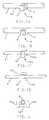
- FIG. 1Ashows a side, fragmented view of a tube of an infusion set passing through an optical sensor in accordance with the principles of the present invention
- FIG. 1Bshows a side view of the infusion set tube and the optical sensor of FIG. 1A, wherein the infusion set tube has expanded in diameter due to increased viscosity or an occlusion within the tube;
- FIG. 1Cshows a side view of the tube portion and optical sensor of FIG. 1A, with the tube portion being contracted in response to decreased pressure caused by an occulsion or viscosity withing the infusion set;
- FIG. 1Dshows a top view of the infusion set tube and the optical sensor of FIG. 1A;
- FIG. 1Eshows an end view of the optical sensor and a cross-sectional view of the infusion set tube shown in FIG. 1A;
- FIG. 2Ashows a side view of a infusion set passing through an alternate embodiment of an optical sensor system in accordance with the principles of the present invention, in which a retaining jacket is used along the infusion set tube to amplify changes in tube diameter responsive to pressure changes within the tube;
- FIG. 2Bshows a top view of the infusion set and optical sensor system of FIG. 2A;
- FIG. 2Cshows a side cross-sectional view of another embodiment of the present invention which operates on principles similar to that of the embodiment shown in FIGS. 2A-2B;
- FIG. 3shows a side, partial cross-sectional view of yet another embodiment of the present invention in which the tube of the infusion set has a thin-walled portion;
- FIG. 4Ashows a side view of yet another embodiment of an optical sensor system made in accordance with the present invention and a portion of the tube of an infusion set passing therethrough;
- FIG. 4Bshows a bottom view of an infusion set and adapter housing in accordance with the principles of the embodiment of FIG. 4 A and configured for placement in an enteral feeding pump;
- FIG. 4Cshows a cross-sectional view of FIG. 4B taken along the plane 4 C— 4 C;
- FIG. 4Dshows a cross-sectional view of a number of different abutment members configurations in accordance with the present invention.
- FIG. 5shows a perspective view of an enteral feeding pump employing one embodiment of an optical sensor system in accordance with the principles of the present invention.
- FIG. 1there is shown a fragmented side view of a tube 4 of an infusion set.
- the tube 4is disposed so that its lower portion 4 a is positioned between an optical signal emitter 8 and an optical signal receiver 12 .
- the optical signal emitter 8 and the optical signal receiver 12form an optical sensor, generally indicated at 16 .
- the tube 4 of the infusion setis formed from a generally elastomeric material such as silicone. However, as set forth below, other materials may be used.
- the tube 4is preferably positioned so that when it is in its smallest state, the lower portion 4 a still partially obstruct light transmitted between the optical signal emitter 8 and the optical signal receiver 12 .
- having the lower portion 4 a of the tube 4 continually obstruct light transmission between the optical signal emitter 8 and the optical signal receiver 12provides an important integrity check on the system by ensuring that the tube is properly loaded in the optical sensor 16 .
- the lower portion 4 a of the tubecan be positioned such that it is slightly occluding the light between the optical signal emitter 8 and the optical signal receiver 12 when at ambient pressure. This is because any occlusion or viscosity increase down stream from the pump mechanism(not shown) will increase pressure, causing the tube 4 to expand and move the lower portion 4 a downwardly between the optical signal emitter 8 and the optical signal receiver 12 . In virtually all scenarios, the portion of the tube 4 downstream from the pump rotor will be at least as large as its ambient state.
- a portion of the tube 4 which is positioned above the pump rotorwill have a vacuum generated within the tube with each rotation (or other actuation) of the pump mechanism. This vacuum is amplified by an upstream occlusion or high viscosity. Thus, a portion of the tube 4 positioned upstream from the pump rotor will partially collapse or have a reduced diameter with each rotation of the pump rotor.
- an upstream portion of the tubewill need to have the lower portion 4 a placed more deeply into the optical signal sensor 16 to ensure that the it continually obstructs light flow between the optical signal emitter 8 and the optical signal receiver 12 .
- the upstream portionwill rarely expand beyond its ambient state.
- a reading by the optical signal sensor 16 that there is no light obstructioncan mean two things. First, it could mean that the tube 4 is not expanding beyond some predetermined threshold to cause it to enter the optical sensor. Second, it could mean that the tube 4 of the infusion set was never loaded into the pump in the first place. However, by keeping the lower portion 4 a of the tube 4 of the infusion set within the optical signal sensor 16 , the ambiguity of the signal can be eliminated. If the optical signal receiver 12 detects no obstruction of light between the optical signal emitter 8 and the optical signal receiver 12 , the tube 4 has not been loaded properly.
- the patient or a health care workermay have already opened a clamp on the infusion set which prevents flow prior to loading of the infusion set in the pump. If the infusion set has been inserted into the catheter in the patient, but not properly loaded into the pump, the solution may be flowing freely under the force of gravity into the patient at a rate far in excess of that desired. For some patients, this free-flow situation can raise serious health concerns, as the patient's body may not be able to handle the sudden “flood” of solution. This is especially true if the solution is medicated.
- the tube 4In addition to always keeping the lower portion 4 a of the tube 4 at least partially within the optical signal sensor 16 , it is also desirable that the tube not be positioned so that it will completely obstruct light transmission between the optical signal emitter 8 and the optical signal receiver 12 during normal operation.
- an integrity check on the optical signal sensoris made each time a reading is processed. If some light is being received by the optical signal receiver 12 , then the sensor 16 must be working. If no light is being received, the optical signal sensor 16 has malfunctioned and an alarm is generated.
- a virtual total obstruction of light transmission between the optical signal emitter 8 and the optical signal receiver 12could also be used to determine when the infusion set has an occlusion or excessive viscosity.
- an ambiguous alarmis created which could mean excessive pressure or a faulty sensor.
- the pumpif the pump detects an occlusion, an improper loading of the tube 4 of the infusion set, or a faulty optical signal sensor 16 , the pump will generate one or more alarms and provide notice of the problem. The patient or health care worker may then correct the problem and restore the solution flow to the desired level.
- FIG. 1Bthere is shown a side view of the infusion set tube 4 positioned between the optical signal emitter 8 and the optical signal receiver 12 .
- the optical signal emitter 8 and the optical signal receiver 12are positioned immediately adjacent to the tube 4 .
- both upstream and downstream portions of the tube 4will be disposed in optical signal sensors 16 positioned near the pump mechanism to monitor pressure changes due to occlusions and viscosity.
- the pumpwill be able to detect both upstream and downstream occlusions and changes in viscosity which may interfere with delivery of the predetermined amount of solution.
- FIG. 1Bshows a tube 4 ′ which has increased in diameter due to an occlusion downstream from the sensor.
- the optical sensor 16detects a pressure increase above a predetermined threshold, an alarm will be generated indicating that the infusion set should be checked. If the pressure detected by the optical signal sensor 16 is so high as to present safety concerns, the pump can be shut down until it has been checked.
- FIG. 1Cshows an upstream portion of the tube 4 ′′ positioned between an optical signal emitter 8 a and an optical signal receiver 12 a .
- the upstream portion of the tube 4 ′′will generally have a vacuum created therein with each rotation of the pump rotor (or other actuating movement of the pump mechanism).
- the tube 4 ′′ in FIG. 1Cis smaller in diameter than the tube 4 in FIG. 1 A and much smaller in diameter than the tube 4 ′ in FIG. 1 B.
- the presence of occlusions or high viscositycan amplify the shrinking and require additional time for the tube to return to its normal diameter. If the tube has not returned to its normal diameter by the time the pump conducts its next rotation, there will be less solution in the tube for movement by the tube, and each rotation of the pump rotor will deliver less solution than when the solution is at normal pressure.
- the pumpcan increase the number or frequency of rotations (or other actuating motion) to compensate for the pressure changes, and thereby ensure that the proper amount of solution is being delivered to the patient. If the occlusion or viscosity is causing too much impediment to solution flow through the tube 4 ′′, the pump can generate an alarm, thereby informing the user or health care worker that the infusion set must be checked.
- the upstream optical signal sensor 16 acan fail.
- the tube 4 ′′ of the infusion setcan be loaded improperly.
- FIG. 1Dthere is shown a top view of the infusion set tube 4 and the optical signal sensor 16 of FIG. 1 A.
- the optical signal emitter 8 and the optical signal receiver 12are positioned immediately adjacent the tube 4 of the infusion set. While the optical signal emitter 8 and the optical signal receiver 12 need not touch the tube 4 , having the two sensors constrict radial expansion on the sides of the tube will cause increased expansion of the tube vertically, thereby amplifying the changes caused by pressure.
- FIG. 1Eshows a cross-sectional view of the tube 4 and an end view of the optical signal emitter 8 and the optical signal receiver 12 . From this view, it is apparent that radial expansion of the tube 4 will interfere with transmission of optical signals, represented by arrows 18 , between the optical signal emitter 8 and the optical signal receiver 12 .
- the extent to which the tube 4 interferes with the light transmissionis proportional to the pressure changes which occur within the tube during operation of the pump. It is not proportional to, the reflective index of the material or whether the material is clear or opaque. Thus, a variety of materials could be used for the tube 4 if desired.
- FIG. 2Ashows a side view of a infusion set 24 passing through an alternate embodiment of an optical sensor system 36 in accordance with the principles of the present invention.
- a jacket 40Disposed along the tube 24 of the infusion set is a jacket 40 . While the tube 24 of the infusion set is formed from a radially expandable material such as silicone, the jacket 40 is formed from a generally rigid material that will have minimal if any radial expansion in the pressure range typically associated with solution feeding systems.
- an window 44In the top of the jacket 40 is an window 44 .
- the window 44exposes a portion 24 a of the tube 24 of the infusion set. Because the jacket 40 constricts expansion of the tube 24 , expansion created by changes in the tube are amplified in the portion 24 a of the tube adjacent the window.
- the optical signal emitter 28 and the optical signal receiver 32disposed on opposing sides of the window 44 , the pressure changes within the infusion set can be more accurately determined due to the amplification created by the jacket 40 .
- FIG. 2Bthere is shown a top view of the infusion set, including the tube 24 and the jacket 40 .
- the optical signal emitter 28 and the optical signal receiver 32 of the optical signal sensor 36are disposed on opposing sides of the window 44 in the jacket so as to monitor the rise and fall of the portion 24 a of the tube 24 exposed by the window 44 .
- FIG. 2Cshows a cross-sectional view of an alternate embodiment of the present invention, which operates in substantially the same manner as the embodiment shown in FIGS. 2A and 2B.
- the infusion setgenerally indicated at 50 , has a rigid tube 52 and a radially expandable tube 54 .
- the rigid tube 52has an opening or window 56 which is covered by a portion 54 a of the radially expandable tube 54 .
- the portion 54 atends to expand to a greater degree than the remainder of the tube 54 because the rigid tube 52 constricts expansion in all but one direction.
- placing the optical signal sensor(not shown in FIG. 2C) adjacent the portion 54 a of the tube 54 provides improved sensitivity.
- the infusion set 60includes a tube 64 disposed between the optical signal emitter (shown in shadow 68 ) and the optical signal receiver (shown in shadow 72 ) of the optical signal sensor 76 .
- the portion 64 a of the tube 64 disposed between the optical signal sensor 76has a thin-walled portion on one side.
- the thin-wall portionis between 0.025 and 0.050.
- the outer circumference of the tube 64and will be between 0.175 and 0.300 thinner than the normal thickness of the tube 64 .
- the thin-walled portion 64 awill expand and contract to a greater extent. The exaggerated expansion and contraction provides increased sensitivity to pressure changes, as the optical signal sensor 76 can more readily detect pressure changes due to the exaggerated movement.
- FIG. 4Athere is shown a side view of yet another embodiment of an optical sensor system made in accordance with the present invention and a portion of the tube of an infusion set passing therethrough.
- the tube 84is disposed generally above an optical signal emitter 88 and an optical signal receiver 92 which form an optical signal sensor, generally indicated at 96 .
- the tube 84is positioned in a generally planar configuration. However, a portion 84 a of the tube 84 positioned above the space between the optical signal emitter 88 and the optical signal receiver 92 is engaged by an abutment member 100 so as to deflect that portion of the tube into the space 104 between the optical signal emitter 88 and the optical signal receiver 92 .
- the abutment member 100serves two valuable functions. First, the abutment member 100 helps to ensure the tube 84 of the infusion set is in the desired location and helps resist movement of the tube which may be caused by the pump mechanism. Second, the abutment member 100 prevents expansion of the tube 84 along the top side thereof adjacent to the optical signal sensor 96 . This causes pressure changes to expand and contract the opposing wall 84 b of the tube in an exaggerated manner to how the sidewalls of the tube will normally respond to pressure changes. As with the embodiments discussed above, this exaggerated movement allows the optical signal sensor 96 to detect smaller changes in pressure, and thereby provide more accuracy in determining pressure changes within the infusion set.
- FIG. 4Bthere is shown a bottom view of the tube 84 of an infusion set 86 and the abutment member 100 as used in accordance with the principles of the present invention.
- the infusion setincludes an upstream intake tube 86 a and a downstream output tube 86 b.
- the tube 84 of the infusion sethas a looped portion 84 c which wraps around the rotor (not shown) of an enteral feeding pump, or similar device.
- the abutment member 100is disposed to engage the tube 84 of the infusion set 86 both upstream and downstream from the pump rotor.
- pressureis monitored both upstream and downstream from the pump rotor to ensure that 1) a known quantity of solution reaches the portion of the tube 84 which engages the pump rotor, and 2) that the solution pumped by the pump rotor reaches the patient.
- the tube 84 of the infusion set 86is typically made from an elastomeric material such as silicone. This allows the tube 84 to stretch and to expand and contract is it is worked by the pump rotor to move solution through the tube.
- the remainder of the infusion set 86need not be formed from silicone. To the contrary, less expensive tubing can be used for the remainder of the infusion set 86 .
- the silicone tube 84 and the remainder of the infusion set 86are typically held together by an adaptor 108 having two connectors 110 . These connectors 110 can be formed as an integral, one piece adaptor including the abutment member 100 , or can be formed separately.
- the enteral feeding pumpis able to determine the viscosity and occlusion's effect on solution flow rate and thereby determine the amount of solution which is being pumped by each rotation of the pump rotor. This is typically done by monitoring the voltage produced by the optical signal receiver.
- the downstream portion 84 ewill receive increased pressure with each rotation of the pump rotor, thereby causing the downstream portion 84 b to expand.
- the expansionwill restrict light flow from the optical signal emitter to the optical signal receiver, thereby decreasing the voltage generated.
- the optical signal sensor(not shown) will produce voltage readings indicative of the excess or prolonged expansion of portion 84 b along the downstream portion 84 e of the tube 84 .
- the enteral feeding pumpcan then generate an alarm indicating an occlusion downstream. This will prevent the patient from being subject to sudden pressure increases which could cause discomfort or even injury.
- the abutment member 100increases the accuracy of the optical signal sensor 96 by exaggerating the expansion (downstream) or contraction (upstream) along the tube portion 84 b . This exaggerated movement enables the enteral feeding pump to more accurately determine pressure by the voltage readings produced by the optical signal sensor.
- FIG. 4Cthere is shown a cross-sectional view of the tube 84 of the infusion set 86 , and fragmented views of the abutment members 100 a and 100 b .
- the monitored propertyis almost always contraction of the tube.
- the end of the projectionshould have a thickness (i.e. a cross-section taken generally co-planar with the cross-section of the tube) with a radius which is 1 ⁇ 8 the diameter of the tube 84 .
- the narrow projection formed by the abutment member 84 aallows the outer edges of the tube 84 to move upward and downwardly. This has been found to increase sensitivity to the vacuum created within the upstream portion 84 d the tube 84 , and thereby enables the voltage reading of the associated optical signal sensor to more accurately indicate the pressure within the tube.
- the downstream portion 84 e of the tube 84generally monitors only pressures at ambient or greater, it is not necessary for the abutment member 100 b to form such a protrusion. Rather, the abutment member 100 b is generally broader and generally presses against the entire top of the tube 84 at the location adjacent the optical signal sensor. As the pressure in the downstream portion 84 e of the tube 84 increases, the relatively flat abutment member 100 b limits expansion of the tube upwardly, thereby causing exaggerated expansion on the opposing side 84 b of the tube 84 .
- FIG. 4Dshows the cross-section of protrusions which are generally squared, semi-oval and triangular.
- FIG. 5there is shown a perspective view of an enteral feeding pump, generally indicated at 130 , formed in accordance with the principles of the present invention.
- the pump 130includes a motor unit 134 with a digital readout 138 and a plurality of control buttons 142 .
- the motor unit 134controls a rotor 146 , which has a plurality of rollers 150 (typically three) which are configured to engage the tube 84 of the infusion set 86 .
- the rollers 150selectively pinch off the tube 84 and push solution contained therein downstream. If no pressure changes where present, one could readily determine the amount of solution moved by the pump 130 by simply counting the rotations. The pressures within the infusion set 86 , however, effect the amount of solution which is moved by each rotation of the rotor 146 . By determining these pressures, one can quite accurately calculate the amount of fluid being pumped. Thus, it is important to track the upstream and downstream pressures in the infusion set 86 .
- the connectors 110 ′ which connect the intake tube 86 a and output tube 86 b of the infusion set 86 to the tube 84are formed integrally with an anti-free flow device 160 which is disposed within the tube 84 in the form of an adaptor housing 164 which nests within a pair of channels 168 on the enteral feeding pump 130 .
- the housingmay also have integrally formed therein one or more abutment members similar to those discussed above.
- a cover 170 which is used to hold the housing 164 to the channels 168 of the enteral feeding pump 130may have one or more abutment members 174 formed thereon.
- Closing the cover 170causes the abutment member 174 to extend through an opening in the housing 164 and to engage the tube 84 .
- the tube 84is then automatically and properly positioned between the optical signal emitter and the optical signal receiver (not visible in FIG. 5) which are disposed along the channels 168 .
- a catch 178can be used to hold the cover 170 closed.
- the enteral feeding pump 130can readily determine and display the amount of solution which is being pumped during a given amount of time. It can also develop a signal when thresholds are exceeded, and can indicate trends in increased or decreased viscosity if desired. Furthermore, if the pump has been set to deliver a predetermined amount of solution in a given time, the enteral feeding pump 130 is able to adjust the rotor frequency (i.e. the number of times the rotor 146 rotates in a given amount of time) to ensure the desired amount of solution has been delivered.
- the present inventionis able to obtain the advantages set forth in U.S. Pat. No. 5,720,721, without the need of using pressure transducers or other similar, costly devices.
- an optical sensorcan be used to provide highly accurate pressure and viscosity information while substantially lowering the cost of the enteral feeding pump.
Landscapes
- Health & Medical Sciences (AREA)
- Biomedical Technology (AREA)
- Hematology (AREA)
- Vascular Medicine (AREA)
- Engineering & Computer Science (AREA)
- Anesthesiology (AREA)
- Physics & Mathematics (AREA)
- Heart & Thoracic Surgery (AREA)
- General Physics & Mathematics (AREA)
- Life Sciences & Earth Sciences (AREA)
- Animal Behavior & Ethology (AREA)
- General Health & Medical Sciences (AREA)
- Public Health (AREA)
- Veterinary Medicine (AREA)
- Infusion, Injection, And Reservoir Apparatuses (AREA)
Abstract
Description
Claims (40)
Priority Applications (13)
| Application Number | Priority Date | Filing Date | Title |
|---|---|---|---|
| US09/836,852US6523414B1 (en) | 2001-04-16 | 2001-04-16 | Optical pressure monitoring system |
| EP01273542.9AEP1381889B1 (en) | 2001-04-16 | 2001-12-12 | Optical pressure monitoring system |
| ES12007683.1TES2603502T3 (en) | 2001-04-16 | 2001-12-12 | Optical pressure monitoring system |
| JP2002582033AJP4143414B2 (en) | 2001-04-16 | 2001-12-12 | Optical pressure monitoring device |
| CNB018231381ACN1221795C (en) | 2001-04-16 | 2001-12-12 | Optical pressure monitoring system |
| EP12007683.1AEP2570826B1 (en) | 2001-04-16 | 2001-12-12 | Optical pressure monitoring system |
| AU2001297726AAU2001297726A1 (en) | 2001-04-16 | 2001-12-12 | Optical pressure monitoring system |
| PCT/US2001/051498WO2002084336A2 (en) | 2001-04-16 | 2001-12-12 | Optical pressure monitoring system |
| DK12007683.1TDK2570826T3 (en) | 2001-04-16 | 2001-12-12 | Optical pressure monitoring system |
| US10/290,557US6907788B2 (en) | 2001-04-16 | 2002-11-08 | Optical pressure monitoring system |
| US11/103,806US7121143B2 (en) | 2001-04-16 | 2005-04-11 | Optical pressure monitoring system |
| US11/549,585US7921718B2 (en) | 2001-04-16 | 2006-10-13 | Optical pressure monitoring system |
| JP2008117985AJP4921413B2 (en) | 2001-04-16 | 2008-04-30 | Injection device |
Applications Claiming Priority (1)
| Application Number | Priority Date | Filing Date | Title |
|---|---|---|---|
| US09/836,852US6523414B1 (en) | 2001-04-16 | 2001-04-16 | Optical pressure monitoring system |
Related Child Applications (1)
| Application Number | Title | Priority Date | Filing Date |
|---|---|---|---|
| US10/290,557DivisionUS6907788B2 (en) | 2001-04-16 | 2002-11-08 | Optical pressure monitoring system |
Publications (1)
| Publication Number | Publication Date |
|---|---|
| US6523414B1true US6523414B1 (en) | 2003-02-25 |
Family
ID=25272889
Family Applications (4)
| Application Number | Title | Priority Date | Filing Date |
|---|---|---|---|
| US09/836,852Expired - LifetimeUS6523414B1 (en) | 2001-04-16 | 2001-04-16 | Optical pressure monitoring system |
| US10/290,557Expired - LifetimeUS6907788B2 (en) | 2001-04-16 | 2002-11-08 | Optical pressure monitoring system |
| US11/103,806Expired - LifetimeUS7121143B2 (en) | 2001-04-16 | 2005-04-11 | Optical pressure monitoring system |
| US11/549,585Expired - Fee RelatedUS7921718B2 (en) | 2001-04-16 | 2006-10-13 | Optical pressure monitoring system |
Family Applications After (3)
| Application Number | Title | Priority Date | Filing Date |
|---|---|---|---|
| US10/290,557Expired - LifetimeUS6907788B2 (en) | 2001-04-16 | 2002-11-08 | Optical pressure monitoring system |
| US11/103,806Expired - LifetimeUS7121143B2 (en) | 2001-04-16 | 2005-04-11 | Optical pressure monitoring system |
| US11/549,585Expired - Fee RelatedUS7921718B2 (en) | 2001-04-16 | 2006-10-13 | Optical pressure monitoring system |
Country Status (8)
| Country | Link |
|---|---|
| US (4) | US6523414B1 (en) |
| EP (2) | EP2570826B1 (en) |
| JP (2) | JP4143414B2 (en) |
| CN (1) | CN1221795C (en) |
| AU (1) | AU2001297726A1 (en) |
| DK (1) | DK2570826T3 (en) |
| ES (1) | ES2603502T3 (en) |
| WO (1) | WO2002084336A2 (en) |
Cited By (82)
| Publication number | Priority date | Publication date | Assignee | Title |
|---|---|---|---|---|
| US20040220542A1 (en)* | 2000-05-11 | 2004-11-04 | David Cise | Apparatus and method for preventing free flow in an infusion line |
| WO2004061399A3 (en)* | 2002-12-30 | 2004-12-29 | James Brugger | Pressure detector for fluid circuits |
| US20050052490A1 (en)* | 2003-04-02 | 2005-03-10 | Seiko Epson Corporation | Liquid ejecting apparatus |
| US20050119625A1 (en)* | 2000-05-11 | 2005-06-02 | Scott Miles | Apparatus and method for preventing free flow in an infusion line |
| US20050178206A1 (en)* | 2001-04-16 | 2005-08-18 | Zevex, Inc. | Optical pressure monitoring system |
| US20050209552A1 (en)* | 2001-04-16 | 2005-09-22 | Beck Kent F | Adaptor for feeding sets |
| US20050234472A1 (en)* | 2004-04-19 | 2005-10-20 | Huebner Randall J | Placement of fasteners into bone |
| US20050278072A1 (en)* | 2004-05-25 | 2005-12-15 | Sherwood Services, Ag. | Flow monitoring system for a flow control apparatus |
| US20060058740A1 (en)* | 2000-05-11 | 2006-03-16 | David Cise | Apparatus and method for preventing free flow in an infusion line |
| US20060288718A1 (en)* | 2005-06-27 | 2006-12-28 | Evapco, Inc. | Dimension sensor and method for stopping expansion of a tube |
| US20070000333A1 (en)* | 2005-06-29 | 2007-01-04 | Nxstage Medical, Inc. | Pressure detector for fluid circuits |
| US20070078381A1 (en)* | 2002-08-12 | 2007-04-05 | Marc Yap | System and method for blockage detection for medication infusion |
| KR100859653B1 (en) | 2004-05-25 | 2008-09-23 | 코비디엔 아게 | Flow monitoring system for flow control |
| US20090049919A1 (en)* | 2007-08-24 | 2009-02-26 | Chris Hills | Ultrasonic air and fluid detector |
| US20090264824A1 (en)* | 2006-12-11 | 2009-10-22 | Tyco Healthcare Group Lp | Pump set and pump with electromagnetic radiation operated interlock |
| US20100056994A1 (en)* | 2006-03-02 | 2010-03-04 | Covidien Ag | Pumping apparatus with secure loading features |
| US20100114063A1 (en)* | 2008-11-04 | 2010-05-06 | Angiodynamics, Inc. | Catheter injection monitoring device |
| USD615644S1 (en) | 2008-08-15 | 2010-05-11 | Ost Medical, Inc. | Anti-free flow modulator |
| US20100204651A1 (en)* | 2009-02-06 | 2010-08-12 | Mark Stringham | Automatic safety occluder |
| US20100209268A1 (en)* | 2009-02-18 | 2010-08-19 | Davis David L | Low cost disposable infusion pump |
| US20100209267A1 (en)* | 2009-02-18 | 2010-08-19 | Davis David L | Infusion pump with integrated permanent magnet |
| US20100211002A1 (en)* | 2009-02-18 | 2010-08-19 | Davis David L | Electromagnetic infusion pump with integral flow monitor |
| US20100212407A1 (en)* | 2009-02-06 | 2010-08-26 | Mark Stringham | Air bubble detector |
| US7805978B2 (en) | 2006-10-24 | 2010-10-05 | Zevex, Inc. | Method for making and using an air bubble detector |
| US20110028899A1 (en)* | 2008-04-01 | 2011-02-03 | Kent Beck | Anti-free flow mechanism for enteral feeding pumps |
| US8052643B2 (en) | 2006-03-02 | 2011-11-08 | Tyco Healthcare Group Lp | Enteral feeding set and interlock device therefor |
| US8142404B2 (en) | 2006-03-02 | 2012-03-27 | Covidien Ag | Controller for pumping apparatus |
| US8142399B2 (en) | 2006-03-02 | 2012-03-27 | Tyco Healthcare Group Lp | Pump set with safety interlock |
| US8154274B2 (en) | 2010-05-11 | 2012-04-10 | Tyco Healthcare Group Lp | Safety interlock |
| US20120266964A1 (en)* | 2009-07-13 | 2012-10-25 | Nestec S.A. | Cassette with infusion set containing anti-freeflow ball valve for peristaltic infusion pump |
| USD672455S1 (en) | 2010-10-01 | 2012-12-11 | Zevex, Inc. | Fluid delivery cassette |
| US8425470B2 (en) | 2008-04-01 | 2013-04-23 | Zevex, Inc. | Anti-free-flow mechanism for enteral feeding pumps |
| US8486020B2 (en) | 2010-08-11 | 2013-07-16 | Zevex, Inc. | Pressure sensor and method of use |
| US8529511B2 (en) | 2007-01-05 | 2013-09-10 | Covidien Lp | Pump set with secure loading features and related methods therefor |
| US8539672B2 (en) | 2010-10-01 | 2013-09-24 | Zevex, Inc. | Method for improving accuracy in a peristaltic pump system based on tubing material properties |
| US8752436B2 (en) | 2010-10-01 | 2014-06-17 | Zevex, Inc. | Pressure sensor seal and method of use |
| US8911414B2 (en) | 2010-10-01 | 2014-12-16 | Zevex, Inc. | Anti free-flow occluder and priming actuator pad |
| US20150032055A1 (en)* | 2012-03-19 | 2015-01-29 | B. Braun Melsungen Ag | Device for supplying and metering a fluid for medicinal purposes |
| US8986252B2 (en) | 2009-07-13 | 2015-03-24 | Nestec S.A. | Cassettes and methods of using same |
| US9004886B2 (en) | 2010-10-01 | 2015-04-14 | Zevex, Inc. | Pressure monitoring system for infusion pumps |
| USD735320S1 (en)* | 2013-11-30 | 2015-07-28 | Zevex, Inc. | Enteral feeding pump cassette |
| USD739931S1 (en)* | 2013-11-30 | 2015-09-29 | Zevex, Inc. | Enteral feeding pump cassette |
| US9151646B2 (en) | 2011-12-21 | 2015-10-06 | Deka Products Limited Partnership | System, method, and apparatus for monitoring, regulating, or controlling fluid flow |
| USD743023S1 (en) | 2014-04-15 | 2015-11-10 | Zevex, Inc. | Enteral feeding pump interface |
| USD745661S1 (en) | 2013-11-06 | 2015-12-15 | Deka Products Limited Partnership | Apparatus to control fluid flow through a tube |
| USD749206S1 (en) | 2013-11-06 | 2016-02-09 | Deka Products Limited Partnership | Apparatus to control fluid flow through a tube |
| USD751690S1 (en) | 2013-11-06 | 2016-03-15 | Deka Products Limited Partnership | Apparatus to control fluid flow through a tube |
| USD751689S1 (en) | 2013-11-06 | 2016-03-15 | Deka Products Limited Partnership | Apparatus to control fluid flow through a tube |
| USD752209S1 (en) | 2013-11-06 | 2016-03-22 | Deka Products Limited Partnership | Apparatus to control fluid flow through a tube |
| US9372486B2 (en) | 2011-12-21 | 2016-06-21 | Deka Products Limited Partnership | System, method, and apparatus for monitoring, regulating, or controlling fluid flow |
| US9435455B2 (en) | 2011-12-21 | 2016-09-06 | Deka Products Limited Partnership | System, method, and apparatus for monitoring, regulating, or controlling fluid flow |
| US9710610B2 (en) | 2012-07-25 | 2017-07-18 | Covidien Lp | Enteral feeding pump with flow adjustment |
| US9724465B2 (en) | 2011-12-21 | 2017-08-08 | Deka Products Limited Partnership | Flow meter |
| US9746094B2 (en) | 2011-12-21 | 2017-08-29 | Deka Products Limited Partnership | Flow meter having a background pattern with first and second portions |
| US9746093B2 (en) | 2011-12-21 | 2017-08-29 | Deka Products Limited Partnership | Flow meter and related system and apparatus |
| US9759343B2 (en) | 2012-12-21 | 2017-09-12 | Deka Products Limited Partnership | Flow meter using a dynamic background image |
| US9852263B2 (en) | 2013-09-24 | 2017-12-26 | Covidien Lp | Feeding set and enteral feeding pump |
| US9907901B2 (en)* | 2015-04-03 | 2018-03-06 | Cirrus Technologies Ltd | Surgical fluid management system |
| US10080836B2 (en) | 2014-01-23 | 2018-09-25 | Zevex, Inc. | Absorption-based optical sensor for detecting infusion pump cassette |
| US10228683B2 (en) | 2011-12-21 | 2019-03-12 | Deka Products Limited Partnership | System, method, and apparatus for monitoring, regulating, or controlling fluid flow |
| US10345175B2 (en) | 2011-05-31 | 2019-07-09 | Nxstage Medical, Inc. | Pressure measurement devices, methods, and systems |
| USD854145S1 (en) | 2016-05-25 | 2019-07-16 | Deka Products Limited Partnership | Apparatus to control fluid flow through a tube |
| US10488848B2 (en) | 2011-12-21 | 2019-11-26 | Deka Products Limited Partnership | System, method, and apparatus for monitoring, regulating, or controlling fluid flow |
| US10842932B1 (en)* | 2012-08-08 | 2020-11-24 | Neurowave Systems Inc. | Intelligent pharmaceutical delivery system with non-concentric pumping mechanism to reduce flow anomaly and method of using |
| US10864312B2 (en) | 2005-11-09 | 2020-12-15 | B. Braun Medical Inc. | Diaphragm pressure pod for medical fluids |
| USD905848S1 (en) | 2016-01-28 | 2020-12-22 | Deka Products Limited Partnership | Apparatus to control fluid flow through a tube |
| US11039753B2 (en) | 2016-12-15 | 2021-06-22 | Baxter International Inc. | System and method for monitoring and determining patient parameters from sensed venous waveform |
| US11039754B2 (en) | 2018-05-14 | 2021-06-22 | Baxter International Inc. | System and method for monitoring and determining patient parameters from sensed venous waveform |
| US11191897B2 (en) | 2019-03-04 | 2021-12-07 | Eitan Medical Ltd. | In cycle pressure measurement |
| US11213460B2 (en) | 2018-09-19 | 2022-01-04 | Vesco Medical Llc | Connectors for infusion pump feeding sets |
| EP4018156A1 (en)* | 2019-08-22 | 2022-06-29 | Fresenius Medical Care Deutschland GmbH | Determination of a tube pressure by means of laser interferometry and device therefor |
| USD964563S1 (en) | 2019-07-26 | 2022-09-20 | Deka Products Limited Partnership | Medical flow clamp |
| CN115279433A (en)* | 2020-03-11 | 2022-11-01 | 泰尔茂株式会社 | Detection device and infusion pump |
| US11504471B2 (en) | 2018-04-12 | 2022-11-22 | Diatech Diabetes, Inc. | Systems and methods for detecting disruptions in fluid delivery devices |
| US11744935B2 (en) | 2016-01-28 | 2023-09-05 | Deka Products Limited Partnership | Apparatus for monitoring, regulating, or controlling fluid flow |
| US11839741B2 (en) | 2019-07-26 | 2023-12-12 | Deka Products Limited Partneship | Apparatus for monitoring, regulating, or controlling fluid flow |
| US11890451B2 (en) | 2019-03-05 | 2024-02-06 | Eitan Medical Ltd. | Anti-free-flow valve |
| US12011567B2 (en) | 2018-02-11 | 2024-06-18 | Eitan Medical Ltd. | Flex-stroke infusion pump |
| US12098738B2 (en) | 2011-12-21 | 2024-09-24 | Deka Products Limited Partnership | System, method, and apparatus for clamping |
| US12186528B2 (en) | 2019-03-05 | 2025-01-07 | Eitan Medical Ltd. | Infusion pump cassette latch |
| US12214162B2 (en) | 2019-03-05 | 2025-02-04 | Eitan Medical Ltd. | Infusion pump with valve compensation |
| US12318576B2 (en) | 2019-03-05 | 2025-06-03 | Eitan Medical Ltd. | Infusion pump with toggling capability |
Families Citing this family (57)
| Publication number | Priority date | Publication date | Assignee | Title |
|---|---|---|---|---|
| EP1229244A1 (en)* | 2001-01-31 | 2002-08-07 | Precimedix S.A. | Occlusion detector for a peristaltic pump |
| US20050267401A1 (en)* | 2004-05-25 | 2005-12-01 | Sherwood Services, Ag. | Safety interlock system for an enteral feeding pump |
| US7537579B2 (en)* | 2002-09-26 | 2009-05-26 | Covidien Ag | Safety interlock system for an enteral feeding pump |
| DE102004001915B3 (en)* | 2004-01-14 | 2005-11-03 | Festo Ag & Co. | Method and device for monitoring the function of valves |
| US7409863B2 (en)* | 2004-10-05 | 2008-08-12 | Sensata Technologies Maryland, Inc. | Pressure sensor |
| US8105279B2 (en) | 2005-09-26 | 2012-01-31 | M2 Group Holdings, Inc. | Dispensing fluid from an infusion pump system |
| DK1933902T3 (en) | 2005-09-26 | 2015-03-23 | Asante Solutions Inc | Infusion Pump WITH A DRIVE THAT HAVE AN PALLEGEME- AND CONGEST HAGE-COMBINATION |
| US7846131B2 (en) | 2005-09-30 | 2010-12-07 | Covidien Ag | Administration feeding set and flow control apparatus with secure loading features |
| EP1772162A1 (en)* | 2005-10-08 | 2007-04-11 | Boehringer Mannheim Gmbh | Infusion system for delivery of a liquid drug |
| EP1818664B1 (en) | 2006-02-13 | 2013-05-01 | F.Hoffmann-La Roche Ag | Device for detection of a change of pressure in a canal of a microdosing device |
| DK2026862T3 (en)* | 2006-06-08 | 2019-10-21 | Hoffmann La Roche | System for detecting an occlusion in a tube |
| US8087019B1 (en) | 2006-10-31 | 2011-12-27 | Aol Inc. | Systems and methods for performing machine-implemented tasks |
| US7840102B2 (en)* | 2007-01-16 | 2010-11-23 | Baker Hughes Incorporated | Distributed optical pressure and temperature sensors |
| US7981102B2 (en) | 2007-05-21 | 2011-07-19 | Asante Solutions, Inc. | Removable controller for an infusion pump |
| US7892199B2 (en) | 2007-05-21 | 2011-02-22 | Asante Solutions, Inc. | Occlusion sensing for an infusion pump |
| US7833196B2 (en) | 2007-05-21 | 2010-11-16 | Asante Solutions, Inc. | Illumination instrument for an infusion pump |
| EP2022519A1 (en)* | 2007-08-10 | 2009-02-11 | F. Hoffmann-La Roche AG | Device for detecting a pressure change in the liquid path of a micro dosing apparatus |
| US7959598B2 (en) | 2008-08-20 | 2011-06-14 | Asante Solutions, Inc. | Infusion pump systems and methods |
| JP5134142B2 (en)* | 2008-09-22 | 2013-01-30 | フラウンホーファー−ゲゼルシャフト ツル フェルデルング デル アンゲヴァンテン フォルシュング エー ファウ | Apparatus and method for measuring at least one flow parameter |
| US8770010B1 (en) | 2009-03-30 | 2014-07-08 | Strain Measurement Devices, Inc. | Integrated detector for detecting bubbles in fluid flow and occlusions in a tube |
| GB2469820A (en)* | 2009-04-28 | 2010-11-03 | Haemair Ltd | Fluid Pressure Sensing Device |
| WO2010133319A1 (en)* | 2009-05-19 | 2010-11-25 | Fresenius Medical Care Deutschland Gmbh | Apparatus and method for identifying a tubing system for an extracorporeal blood treatment device |
| SG178459A1 (en)* | 2009-08-26 | 2012-03-29 | Nestec Sa | Infra-red reflective occlusion sensors |
| US8287488B2 (en)* | 2009-12-08 | 2012-10-16 | Roche Diagnostics Operations, Inc. | Holographic occlusion detection system for infusion pumps |
| US8689439B2 (en) | 2010-08-06 | 2014-04-08 | Abbott Laboratories | Method for forming a tube for use with a pump delivery system |
| US8377001B2 (en) | 2010-10-01 | 2013-02-19 | Abbott Laboratories | Feeding set for a peristaltic pump system |
| US8377000B2 (en)* | 2010-10-01 | 2013-02-19 | Abbott Laboratories | Enteral feeding apparatus having a feeding set |
| US8808230B2 (en) | 2011-09-07 | 2014-08-19 | Asante Solutions, Inc. | Occlusion detection for an infusion pump system |
| DE102012102274B4 (en) | 2012-03-19 | 2018-05-24 | B. Braun Melsungen Ag | piston pump |
| CN104245019B (en)* | 2012-04-24 | 2017-08-15 | 诺和诺德股份有限公司 | Delivery device and method for detecting administration done state |
| US8454562B1 (en) | 2012-07-20 | 2013-06-04 | Asante Solutions, Inc. | Infusion pump system and method |
| US9457141B2 (en) | 2013-06-03 | 2016-10-04 | Bigfoot Biomedical, Inc. | Infusion pump system and method |
| US9561324B2 (en) | 2013-07-19 | 2017-02-07 | Bigfoot Biomedical, Inc. | Infusion pump system and method |
| KR102235689B1 (en) | 2013-07-30 | 2021-04-02 | 삼성전자주식회사 | Liquid occlusion detection apparatus and method |
| US10569015B2 (en) | 2013-12-02 | 2020-02-25 | Bigfoot Biomedical, Inc. | Infusion pump system and method |
| US10137246B2 (en) | 2014-08-06 | 2018-11-27 | Bigfoot Biomedical, Inc. | Infusion pump assembly and method |
| US9919096B2 (en) | 2014-08-26 | 2018-03-20 | Bigfoot Biomedical, Inc. | Infusion pump system and method |
| US9878097B2 (en) | 2015-04-29 | 2018-01-30 | Bigfoot Biomedical, Inc. | Operating an infusion pump system |
| US20200268966A1 (en)* | 2015-11-16 | 2020-08-27 | Onefusion Ag | Procedure to operate a perfusion device and perfusion device to implement the procedure |
| AU2016385454B2 (en) | 2016-01-05 | 2021-12-16 | Bigfoot Biomedical, Inc. | Operating multi-modal medicine delivery systems |
| HK1256995A1 (en) | 2016-01-14 | 2019-10-11 | Bigfoot Biomedical, Inc. | Occlusion resolution in medication delivery devices, systems, and methods |
| USD809134S1 (en) | 2016-03-10 | 2018-01-30 | Bigfoot Biomedical, Inc. | Infusion pump assembly |
| CN109414545B (en) | 2016-06-16 | 2021-07-27 | 史密斯医疗Asd公司 | Assembly and method for infusion pump system administration set |
| AU2017335762B2 (en) | 2016-09-27 | 2022-03-17 | Bigfoot Biomedical, Inc. | Medicine injection and disease management systems, devices, and methods |
| USD836769S1 (en) | 2016-12-12 | 2018-12-25 | Bigfoot Biomedical, Inc. | Insulin delivery controller |
| EP3500161A4 (en) | 2016-12-12 | 2020-01-08 | Bigfoot Biomedical, Inc. | ALARMS AND WARNINGS FOR MEDICINE DELIVERY DEVICES AND RELATED SYSTEMS AND METHODS |
| USD839294S1 (en) | 2017-06-16 | 2019-01-29 | Bigfoot Biomedical, Inc. | Display screen with graphical user interface for closed-loop medication delivery |
| EP3651647A1 (en) | 2017-07-13 | 2020-05-20 | Bigfoot Biomedical, Inc. | Multi-scale display of blood glucose information |
| CA3069538A1 (en) | 2017-07-19 | 2019-01-24 | Smiths Medical Asd, Inc. | Housing arrangements for infusion pumps |
| US10794786B2 (en) | 2018-09-24 | 2020-10-06 | Honeywell International Inc. | Miniature size force sensor with bubble detection capabilities |
| CN109793964A (en)* | 2019-01-31 | 2019-05-24 | 广州友沃医疗用品有限公司 | A high-pressure injection hose and an injection device and pressure feedback method using the same |
| US12070578B2 (en) | 2019-04-19 | 2024-08-27 | Carefusion 303, Inc. | Medical tubing dimension scanning |
| DE102020207084A1 (en)* | 2020-06-05 | 2021-12-09 | B. Braun Melsungen Aktiengesellschaft | Infusion filter |
| US11506556B2 (en)* | 2020-09-30 | 2022-11-22 | Rosenmount Inc. | Single-use plastic pressure sensor |
| KR102451958B1 (en)* | 2020-12-22 | 2022-10-11 | 재단법인 오송첨단의료산업진흥재단 | Non-contact pressure measuring system for balloon catheter and method for measuring pressure using the same |
| JP2022145484A (en)* | 2021-03-18 | 2022-10-04 | セイコーホールディングス株式会社 | Flow detection device |
| CN116591804A (en)* | 2023-06-09 | 2023-08-15 | 瑞安市中铃科技有限公司 | A self-sealing oil pan |
Citations (22)
| Publication number | Priority date | Publication date | Assignee | Title |
|---|---|---|---|---|
| US4244365A (en) | 1979-03-26 | 1981-01-13 | Cutter Laboratories, Inc. | Device for use in detecting occlusion in an infusion system |
| US4322979A (en) | 1979-09-17 | 1982-04-06 | Siemens Aktiengesellschaft | Optical device for measuring slight differences of pressure by means of a change in light intensity |
| US4322978A (en) | 1979-09-17 | 1982-04-06 | Siemens Aktiengesellschaft | Optical device for measuring slight pressure differences by means of light intensity changes |
| US4554837A (en) | 1984-05-04 | 1985-11-26 | Anatros Corporation | Reflective optical fluid pressure sensor |
| US4555949A (en) | 1984-05-04 | 1985-12-03 | Anatros Corporation | Optical fluid pressure sensor |
| US4612810A (en) | 1984-02-13 | 1986-09-23 | U.S. Philips Corporation | Optical pressure sensor |
| US4631529A (en) | 1984-10-17 | 1986-12-23 | Ivek Corporation | Electro-optical fluid detector |
| EP0261860A2 (en) | 1986-09-24 | 1988-03-30 | Cannonbear Inc. | Sensor and method for ullage level and flow detection |
| US4762518A (en) | 1986-08-01 | 1988-08-09 | Pancretec, Inc. | Blockage hazard alarm in an intravenous system |
| US4829448A (en) | 1984-09-24 | 1989-05-09 | Vi-Tal Hospital Products Ltd. | Air-in-line detector |
| US4833918A (en) | 1986-09-24 | 1989-05-30 | Cannonbear, Inc. | Sensor and method for ullage level and flow detection |
| US4908676A (en) | 1987-12-18 | 1990-03-13 | Bio-Recovery Systems, Inc. | Sensors for dissolved substances in fluids |
| US4920336A (en) | 1988-11-22 | 1990-04-24 | Fisher Scientific Company | Method and apparatus for monitoring the level of the contents in a container |
| US5098380A (en) | 1988-03-30 | 1992-03-24 | Nikkiso Co., Ltd. | Method of and apparatus for detecting an occlusion of liquid transfusion tube |
| US5260665A (en) | 1991-04-30 | 1993-11-09 | Ivac Corporation | In-line fluid monitor system and method |
| US5305237A (en) | 1991-07-12 | 1994-04-19 | Union Tank Car Company | Method and apparatus for monitoring a flowable material in a transportable vessel |
| US5445622A (en)* | 1994-12-20 | 1995-08-29 | Brown; Eric W. | Flow switch device for medical applications |
| US5741216A (en) | 1992-04-10 | 1998-04-21 | Novo Nordisk A/S | Pressure monitor |
| US5853386A (en) | 1996-07-25 | 1998-12-29 | Alaris Medical Systems, Inc. | Infusion device with disposable elements |
| US5935106A (en) | 1994-07-27 | 1999-08-10 | Sims Deltec, Inc. | Occlusion detection system for an infusion pump |
| US5983725A (en) | 1996-04-27 | 1999-11-16 | Forschungszenlrum Karlsruhe Gmbh | Tactile pressure sensor |
| US6290681B1 (en)* | 1994-12-20 | 2001-09-18 | Remote Medical Corporation | Flow monitoring device for medical application |
Family Cites Families (36)
| Publication number | Priority date | Publication date | Assignee | Title |
|---|---|---|---|---|
| US3994599A (en)* | 1974-01-23 | 1976-11-30 | Owens-Illinois, Inc. | Method and apparatus for measuring wall thickness and concentricity of tubular glass articles |
| US3978731A (en)* | 1974-02-25 | 1976-09-07 | United Technologies Corporation | Surface acoustic wave transducer |
| JPS5631758A (en)* | 1979-08-24 | 1981-03-31 | Sharp Kk | Detector for clogging condition of flexible tube |
| JPS56113083A (en)* | 1980-02-12 | 1981-09-05 | Terumo Corp | Choke detection method and device for peristaltic liquid pump |
| JPS58163860A (en) | 1982-03-23 | 1983-09-28 | Nissan Motor Co Ltd | Transmission oil seal lubrication system |
| US4492463A (en) | 1982-03-29 | 1985-01-08 | At&T Bell Laboratories | Method for inspecting multilayer transparent rods |
| JPS58163860U (en)* | 1982-04-28 | 1983-10-31 | シャープ株式会社 | Blockage detection device for flexible tubes |
| US4606638A (en) | 1983-11-03 | 1986-08-19 | Zygo Corporation | Distance measuring interferometer and method of use |
| US4618261A (en)* | 1984-01-16 | 1986-10-21 | Massachusetts Institute Of Technology | Optical gap measuring |
| US4624413A (en)* | 1985-01-23 | 1986-11-25 | Corsette Douglas Frank | Trigger type sprayer |
| GB8622988D0 (en) | 1986-09-24 | 1986-10-29 | Westland Plc | Joining thermoplastic materials |
| US4882575A (en)* | 1987-01-28 | 1989-11-21 | Sharp Kabushiki Kaisha | Monitor for blocked condition in tube for fluid infusion pump |
| FR2628635B1 (en)* | 1988-03-21 | 1992-10-23 | Microtechnic Sa | SINGLE USE SYRINGE |
| US5074756A (en)* | 1988-05-17 | 1991-12-24 | Patient Solutions, Inc. | Infusion device with disposable elements |
| JPH021805A (en) | 1988-06-10 | 1990-01-08 | Nec Corp | Light transmission/reception module |
| US5008556A (en)* | 1989-07-24 | 1991-04-16 | Becton, Dickinson And Company | Measuring a gap between a tube and a float |
| US5176631A (en)* | 1989-09-05 | 1993-01-05 | Pacesetter Infusion, Ltd. | Ultrasonic air-in-line detector for detecting entrained air in a medication infusion system |
| US5029621A (en)* | 1990-04-12 | 1991-07-09 | Clintec Nutrition Co. | Push back procedure for preventing drop-former droplet formation in a vacuum assisted solution transfer system with upstream occulusion |
| US5181912A (en)* | 1991-12-05 | 1993-01-26 | Roy Hammett | Non-reusable syringe |
| GB9422826D0 (en)* | 1994-11-11 | 1995-01-04 | Spraysol Gmbh | Dispenser for liquid products |
| US5514102A (en)* | 1995-05-05 | 1996-05-07 | Zevex Incorporated | Pressure monitoring enteral feeding system and method |
| US5657000A (en)* | 1995-06-02 | 1997-08-12 | Cobe Laboratories, Inc. | Peristaltic pump occlusion detector and adjuster |
| US5672887A (en)* | 1995-11-29 | 1997-09-30 | Shaw; Benjamin G. | Optical detector for air in fluid line the same |
| US5860938A (en)* | 1996-03-07 | 1999-01-19 | Scimed Life Systems, Inc. | Medical pressure sensing guide wire |
| JP3634071B2 (en)* | 1996-05-29 | 2005-03-30 | 株式会社吉野工業所 | Trigger type ejector return spring device |
| US5964377A (en)* | 1997-10-14 | 1999-10-12 | S. C. Johnson & Son, Inc. | Manually operable pump for mixing and dispensing primary and secondary fluids |
| JP4615726B2 (en)* | 1998-12-04 | 2011-01-19 | ウェザーフォード/ラム インコーポレーテッド | Bragg grating pressure sensor |
| US6490931B1 (en)* | 1998-12-04 | 2002-12-10 | Weatherford/Lamb, Inc. | Fused tension-based fiber grating pressure sensor |
| US6116472A (en)* | 1998-12-15 | 2000-09-12 | Calmar Inc. | Trigger acutated pump sprayer |
| US6463813B1 (en)* | 1999-06-25 | 2002-10-15 | Weatherford/Lamb, Inc. | Displacement based pressure sensor measuring unsteady pressure in a pipe |
| US7815612B2 (en) | 2000-05-11 | 2010-10-19 | Zevex, Inc. | Apparatus and method for preventing free flow in an infusion line |
| US7150727B2 (en) | 2000-05-11 | 2006-12-19 | Zevex, Inc. | Apparatus and method for preventing free flow in an infusion line |
| US6595950B1 (en) | 2000-05-11 | 2003-07-22 | Zevex, Inc. | Apparatus and method for preventing free flow in an infusion line |
| US6659976B2 (en) | 2001-04-16 | 2003-12-09 | Zevek, Inc. | Feeding set adaptor |
| US6523414B1 (en) | 2001-04-16 | 2003-02-25 | Zevex, Inc. | Optical pressure monitoring system |
| US6531708B1 (en) | 2001-04-16 | 2003-03-11 | Zevex, Inc. | Optical bubble detection system |
- 2001
- 2001-04-16USUS09/836,852patent/US6523414B1/ennot_activeExpired - Lifetime
- 2001-12-12JPJP2002582033Apatent/JP4143414B2/ennot_activeExpired - Lifetime
- 2001-12-12ESES12007683.1Tpatent/ES2603502T3/ennot_activeExpired - Lifetime
- 2001-12-12EPEP12007683.1Apatent/EP2570826B1/ennot_activeExpired - Lifetime
- 2001-12-12DKDK12007683.1Tpatent/DK2570826T3/enactive
- 2001-12-12AUAU2001297726Apatent/AU2001297726A1/ennot_activeAbandoned
- 2001-12-12EPEP01273542.9Apatent/EP1381889B1/ennot_activeExpired - Lifetime
- 2001-12-12CNCNB018231381Apatent/CN1221795C/ennot_activeExpired - Lifetime
- 2001-12-12WOPCT/US2001/051498patent/WO2002084336A2/enactiveApplication Filing
- 2002
- 2002-11-08USUS10/290,557patent/US6907788B2/ennot_activeExpired - Lifetime
- 2005
- 2005-04-11USUS11/103,806patent/US7121143B2/ennot_activeExpired - Lifetime
- 2006
- 2006-10-13USUS11/549,585patent/US7921718B2/ennot_activeExpired - Fee Related
- 2008
- 2008-04-30JPJP2008117985Apatent/JP4921413B2/ennot_activeExpired - Lifetime
Patent Citations (22)
| Publication number | Priority date | Publication date | Assignee | Title |
|---|---|---|---|---|
| US4244365A (en) | 1979-03-26 | 1981-01-13 | Cutter Laboratories, Inc. | Device for use in detecting occlusion in an infusion system |
| US4322979A (en) | 1979-09-17 | 1982-04-06 | Siemens Aktiengesellschaft | Optical device for measuring slight differences of pressure by means of a change in light intensity |
| US4322978A (en) | 1979-09-17 | 1982-04-06 | Siemens Aktiengesellschaft | Optical device for measuring slight pressure differences by means of light intensity changes |
| US4612810A (en) | 1984-02-13 | 1986-09-23 | U.S. Philips Corporation | Optical pressure sensor |
| US4554837A (en) | 1984-05-04 | 1985-11-26 | Anatros Corporation | Reflective optical fluid pressure sensor |
| US4555949A (en) | 1984-05-04 | 1985-12-03 | Anatros Corporation | Optical fluid pressure sensor |
| US4829448A (en) | 1984-09-24 | 1989-05-09 | Vi-Tal Hospital Products Ltd. | Air-in-line detector |
| US4631529A (en) | 1984-10-17 | 1986-12-23 | Ivek Corporation | Electro-optical fluid detector |
| US4762518A (en) | 1986-08-01 | 1988-08-09 | Pancretec, Inc. | Blockage hazard alarm in an intravenous system |
| US4833918A (en) | 1986-09-24 | 1989-05-30 | Cannonbear, Inc. | Sensor and method for ullage level and flow detection |
| EP0261860A2 (en) | 1986-09-24 | 1988-03-30 | Cannonbear Inc. | Sensor and method for ullage level and flow detection |
| US4908676A (en) | 1987-12-18 | 1990-03-13 | Bio-Recovery Systems, Inc. | Sensors for dissolved substances in fluids |
| US5098380A (en) | 1988-03-30 | 1992-03-24 | Nikkiso Co., Ltd. | Method of and apparatus for detecting an occlusion of liquid transfusion tube |
| US4920336A (en) | 1988-11-22 | 1990-04-24 | Fisher Scientific Company | Method and apparatus for monitoring the level of the contents in a container |
| US5260665A (en) | 1991-04-30 | 1993-11-09 | Ivac Corporation | In-line fluid monitor system and method |
| US5305237A (en) | 1991-07-12 | 1994-04-19 | Union Tank Car Company | Method and apparatus for monitoring a flowable material in a transportable vessel |
| US5741216A (en) | 1992-04-10 | 1998-04-21 | Novo Nordisk A/S | Pressure monitor |
| US5935106A (en) | 1994-07-27 | 1999-08-10 | Sims Deltec, Inc. | Occlusion detection system for an infusion pump |
| US5445622A (en)* | 1994-12-20 | 1995-08-29 | Brown; Eric W. | Flow switch device for medical applications |
| US6290681B1 (en)* | 1994-12-20 | 2001-09-18 | Remote Medical Corporation | Flow monitoring device for medical application |
| US5983725A (en) | 1996-04-27 | 1999-11-16 | Forschungszenlrum Karlsruhe Gmbh | Tactile pressure sensor |
| US5853386A (en) | 1996-07-25 | 1998-12-29 | Alaris Medical Systems, Inc. | Infusion device with disposable elements |
Cited By (153)
| Publication number | Priority date | Publication date | Assignee | Title |
|---|---|---|---|---|
| US20060058740A1 (en)* | 2000-05-11 | 2006-03-16 | David Cise | Apparatus and method for preventing free flow in an infusion line |
| US7976513B2 (en) | 2000-05-11 | 2011-07-12 | Zevex, Inc. | Apparatus and method for selectively controlling flow in an infusion line |
| US20040220542A1 (en)* | 2000-05-11 | 2004-11-04 | David Cise | Apparatus and method for preventing free flow in an infusion line |
| US20050119625A1 (en)* | 2000-05-11 | 2005-06-02 | Scott Miles | Apparatus and method for preventing free flow in an infusion line |
| US7815612B2 (en)* | 2000-05-11 | 2010-10-19 | Zevex, Inc. | Apparatus and method for preventing free flow in an infusion line |
| US20070151346A1 (en)* | 2001-04-16 | 2007-07-05 | Malmstrom James A | Optical Pressure Monitoring System |
| US20050178206A1 (en)* | 2001-04-16 | 2005-08-18 | Zevex, Inc. | Optical pressure monitoring system |
| US20050209552A1 (en)* | 2001-04-16 | 2005-09-22 | Beck Kent F | Adaptor for feeding sets |
| US7070575B2 (en) | 2001-04-16 | 2006-07-04 | Zevex, Inc. | Adaptor for feeding sets |
| US7121143B2 (en) | 2001-04-16 | 2006-10-17 | Zevex, Inc. | Optical pressure monitoring system |
| US7921718B2 (en) | 2001-04-16 | 2011-04-12 | Zevex, Inc. | Optical pressure monitoring system |
| US7462163B2 (en)* | 2002-08-12 | 2008-12-09 | Lma North America, Inc. | System and method for blockage detection for medication infusion |
| US20070078381A1 (en)* | 2002-08-12 | 2007-04-05 | Marc Yap | System and method for blockage detection for medication infusion |
| WO2004061399A3 (en)* | 2002-12-30 | 2004-12-29 | James Brugger | Pressure detector for fluid circuits |
| US20050052490A1 (en)* | 2003-04-02 | 2005-03-10 | Seiko Epson Corporation | Liquid ejecting apparatus |
| US7318638B2 (en)* | 2003-04-02 | 2008-01-15 | Seiko Epson Corporation | Liquid ejecting apparatus |
| US20050234472A1 (en)* | 2004-04-19 | 2005-10-20 | Huebner Randall J | Placement of fasteners into bone |
| US20070083292A1 (en)* | 2004-05-25 | 2007-04-12 | Sherwood Services Ag | Occlusion system and method for a flow control apparatus |
| KR100859653B1 (en) | 2004-05-25 | 2008-09-23 | 코비디엔 아게 | Flow monitoring system for flow control |
| US7447566B2 (en) | 2004-05-25 | 2008-11-04 | Covidien Ag | Occlusion system and method for a flow control apparatus |
| US7092797B2 (en)* | 2004-05-25 | 2006-08-15 | Sherwood Services Ag | Flow monitoring system for a flow control apparatus |
| US20050278072A1 (en)* | 2004-05-25 | 2005-12-15 | Sherwood Services, Ag. | Flow monitoring system for a flow control apparatus |
| US20060288718A1 (en)* | 2005-06-27 | 2006-12-28 | Evapco, Inc. | Dimension sensor and method for stopping expansion of a tube |
| US7501596B2 (en)* | 2005-06-27 | 2009-03-10 | Evapco, Inc. | Dimension sensor and method for stopping expansion of a tube |
| US7337674B2 (en) | 2005-06-29 | 2008-03-04 | Nx Stage Medical, Inc. | Pressure detector for fluid circuits |
| US20070000333A1 (en)* | 2005-06-29 | 2007-01-04 | Nxstage Medical, Inc. | Pressure detector for fluid circuits |
| US10864312B2 (en) | 2005-11-09 | 2020-12-15 | B. Braun Medical Inc. | Diaphragm pressure pod for medical fluids |
| US20100056994A1 (en)* | 2006-03-02 | 2010-03-04 | Covidien Ag | Pumping apparatus with secure loading features |
| US8142399B2 (en) | 2006-03-02 | 2012-03-27 | Tyco Healthcare Group Lp | Pump set with safety interlock |
| US8142404B2 (en) | 2006-03-02 | 2012-03-27 | Covidien Ag | Controller for pumping apparatus |
| US8052642B2 (en) | 2006-03-02 | 2011-11-08 | Covidien Ag | Pumping apparatus with secure loading features |
| US8052643B2 (en) | 2006-03-02 | 2011-11-08 | Tyco Healthcare Group Lp | Enteral feeding set and interlock device therefor |
| US9402789B2 (en) | 2006-03-02 | 2016-08-02 | Covidien Ag | Pump set having secure loading features |
| US20100306986A1 (en)* | 2006-10-24 | 2010-12-09 | Riley Timothy A | Method for making and using an air bubble detector |
| US7805978B2 (en) | 2006-10-24 | 2010-10-05 | Zevex, Inc. | Method for making and using an air bubble detector |
| US7818992B2 (en) | 2006-10-24 | 2010-10-26 | Zevex, Inc. | Universal air bubble detector |
| US8910370B2 (en) | 2006-10-24 | 2014-12-16 | Zevex, Inc. | Method of making a universal bubble detector |
| US8225639B2 (en) | 2006-10-24 | 2012-07-24 | Zevex, Inc. | Universal air bubble detector |
| US8053721B2 (en) | 2006-12-11 | 2011-11-08 | Tyco Healthcare Group Lp | Pump set and pump with electromagnetic radiation operated interlock |
| US20090264824A1 (en)* | 2006-12-11 | 2009-10-22 | Tyco Healthcare Group Lp | Pump set and pump with electromagnetic radiation operated interlock |
| US8529511B2 (en) | 2007-01-05 | 2013-09-10 | Covidien Lp | Pump set with secure loading features and related methods therefor |
| US7987722B2 (en) | 2007-08-24 | 2011-08-02 | Zevex, Inc. | Ultrasonic air and fluid detector |
| US20090049919A1 (en)* | 2007-08-24 | 2009-02-26 | Chris Hills | Ultrasonic air and fluid detector |
| US20110028899A1 (en)* | 2008-04-01 | 2011-02-03 | Kent Beck | Anti-free flow mechanism for enteral feeding pumps |
| US8425470B2 (en) | 2008-04-01 | 2013-04-23 | Zevex, Inc. | Anti-free-flow mechanism for enteral feeding pumps |
| US8343111B2 (en) | 2008-04-01 | 2013-01-01 | Zevex, Inc. | Anti-free flow mechanism for enteral feeding pumps |
| USD615644S1 (en) | 2008-08-15 | 2010-05-11 | Ost Medical, Inc. | Anti-free flow modulator |
| US20100114063A1 (en)* | 2008-11-04 | 2010-05-06 | Angiodynamics, Inc. | Catheter injection monitoring device |
| US8739601B2 (en) | 2009-02-06 | 2014-06-03 | Zevex, Inc. | Air bubble detector |
| US8491543B2 (en) | 2009-02-06 | 2013-07-23 | Zevex, Inc. | Automatic safety occluder |
| US8646309B2 (en) | 2009-02-06 | 2014-02-11 | Zevek, Inc. | Air bubble detector |
| US8539812B2 (en) | 2009-02-06 | 2013-09-24 | Zevek, Inc. | Air bubble detector |
| US20100212407A1 (en)* | 2009-02-06 | 2010-08-26 | Mark Stringham | Air bubble detector |
| US20100204651A1 (en)* | 2009-02-06 | 2010-08-12 | Mark Stringham | Automatic safety occluder |
| US7998121B2 (en) | 2009-02-06 | 2011-08-16 | Zevex, Inc. | Automatic safety occluder |
| US8197235B2 (en) | 2009-02-18 | 2012-06-12 | Davis David L | Infusion pump with integrated permanent magnet |
| US20100209267A1 (en)* | 2009-02-18 | 2010-08-19 | Davis David L | Infusion pump with integrated permanent magnet |
| US20100209268A1 (en)* | 2009-02-18 | 2010-08-19 | Davis David L | Low cost disposable infusion pump |
| US8353864B2 (en) | 2009-02-18 | 2013-01-15 | Davis David L | Low cost disposable infusion pump |
| US20100211002A1 (en)* | 2009-02-18 | 2010-08-19 | Davis David L | Electromagnetic infusion pump with integral flow monitor |
| US20120266964A1 (en)* | 2009-07-13 | 2012-10-25 | Nestec S.A. | Cassette with infusion set containing anti-freeflow ball valve for peristaltic infusion pump |
| US8986252B2 (en) | 2009-07-13 | 2015-03-24 | Nestec S.A. | Cassettes and methods of using same |
| US9440022B2 (en)* | 2009-07-13 | 2016-09-13 | Nestec S.A. | Cassette with infusion set containing anti-freeflow ball valve for peristaltic infusion pump |
| US9962483B2 (en) | 2009-07-13 | 2018-05-08 | Nestec S.A. | Cassette with infusion set containing anti-freeflow ball valve for peristaltic infusion pump |
| US8760146B2 (en) | 2010-05-11 | 2014-06-24 | Covidien Lp | Safety interlock |
| US8154274B2 (en) | 2010-05-11 | 2012-04-10 | Tyco Healthcare Group Lp | Safety interlock |
| US8486020B2 (en) | 2010-08-11 | 2013-07-16 | Zevex, Inc. | Pressure sensor and method of use |
| USD672455S1 (en) | 2010-10-01 | 2012-12-11 | Zevex, Inc. | Fluid delivery cassette |
| US9004886B2 (en) | 2010-10-01 | 2015-04-14 | Zevex, Inc. | Pressure monitoring system for infusion pumps |
| US8539672B2 (en) | 2010-10-01 | 2013-09-24 | Zevex, Inc. | Method for improving accuracy in a peristaltic pump system based on tubing material properties |
| US8911414B2 (en) | 2010-10-01 | 2014-12-16 | Zevex, Inc. | Anti free-flow occluder and priming actuator pad |
| US8752436B2 (en) | 2010-10-01 | 2014-06-17 | Zevex, Inc. | Pressure sensor seal and method of use |
| US11529448B2 (en) | 2011-05-31 | 2022-12-20 | Nxstage Medical, Inc. | Pressure measurement devices, methods, and systems |
| US12171926B2 (en) | 2011-05-31 | 2024-12-24 | Nxstage Medical, Inc. | Pressure measurement devices, methods, and systems |
| US10345175B2 (en) | 2011-05-31 | 2019-07-09 | Nxstage Medical, Inc. | Pressure measurement devices, methods, and systems |
| US10844970B2 (en) | 2011-12-21 | 2020-11-24 | Deka Products Limited Partnership | Flow meter |
| US11738143B2 (en) | 2011-12-21 | 2023-08-29 | Deka Products Limited Partnership | Flow meier having a valve |
| US10739759B2 (en) | 2011-12-21 | 2020-08-11 | Deka Products Limited Partnership | System, method, and apparatus for monitoring, regulating, or controlling fluid flow |
| US9372486B2 (en) | 2011-12-21 | 2016-06-21 | Deka Products Limited Partnership | System, method, and apparatus for monitoring, regulating, or controlling fluid flow |
| US10488848B2 (en) | 2011-12-21 | 2019-11-26 | Deka Products Limited Partnership | System, method, and apparatus for monitoring, regulating, or controlling fluid flow |
| US9435455B2 (en) | 2011-12-21 | 2016-09-06 | Deka Products Limited Partnership | System, method, and apparatus for monitoring, regulating, or controlling fluid flow |
| US12100507B2 (en) | 2011-12-21 | 2024-09-24 | Deka Products Limited Partnership | System, method, and apparatus for monitoring, regulating, or controlling fluid flow |
| US10436342B2 (en) | 2011-12-21 | 2019-10-08 | Deka Products Limited Partnership | Flow meter and related method |
| US9724465B2 (en) | 2011-12-21 | 2017-08-08 | Deka Products Limited Partnership | Flow meter |
| US9724467B2 (en) | 2011-12-21 | 2017-08-08 | Deka Products Limited Partnership | Flow meter |
| US9724466B2 (en) | 2011-12-21 | 2017-08-08 | Deka Products Limited Partnership | Flow meter |
| US9746094B2 (en) | 2011-12-21 | 2017-08-29 | Deka Products Limited Partnership | Flow meter having a background pattern with first and second portions |
| US9746093B2 (en) | 2011-12-21 | 2017-08-29 | Deka Products Limited Partnership | Flow meter and related system and apparatus |
| US9151646B2 (en) | 2011-12-21 | 2015-10-06 | Deka Products Limited Partnership | System, method, and apparatus for monitoring, regulating, or controlling fluid flow |
| US9772044B2 (en) | 2011-12-21 | 2017-09-26 | Deka Products Limited Partnership | Flow metering using a difference image for liquid parameter estimation |
| US12098738B2 (en) | 2011-12-21 | 2024-09-24 | Deka Products Limited Partnership | System, method, and apparatus for clamping |
| US11793928B2 (en) | 2011-12-21 | 2023-10-24 | Deka Products Limited Partnership | Flow meter and related method |
| US10876868B2 (en) | 2011-12-21 | 2020-12-29 | Deka Products Limited Partnership | System, method, and apparatus for monitoring, regulating, or controlling fluid flow |
| US9856990B2 (en) | 2011-12-21 | 2018-01-02 | Deka Products Limited Partnership | Flow metering using a difference image for liquid parameter estimation |
| US10718445B2 (en) | 2011-12-21 | 2020-07-21 | Deka Products Limited Partnership | Flow meter having a valve |
| US11574407B2 (en) | 2011-12-21 | 2023-02-07 | Deka Products Limited Partnership | System, method, and apparatus for monitoring, regulating, or controlling fluid flow |
| US11449037B2 (en) | 2011-12-21 | 2022-09-20 | Deka Products Limited Partnership | System, method, and apparatus for monitoring, regulating, or controlling fluid flow |
| US11339887B2 (en) | 2011-12-21 | 2022-05-24 | Deka Products Limited Partnership | Flow meter and related method |
| US10228683B2 (en) | 2011-12-21 | 2019-03-12 | Deka Products Limited Partnership | System, method, and apparatus for monitoring, regulating, or controlling fluid flow |
| US9976665B2 (en) | 2011-12-21 | 2018-05-22 | Deka Products Limited Partnership | Flow meter |
| US10894638B2 (en) | 2011-12-21 | 2021-01-19 | Deka Products Limited Partnership | System, method, and apparatus for monitoring, regulating, or controlling fluid flow |
| US10088346B2 (en) | 2011-12-21 | 2018-10-02 | Deka Products Limited Partnership | System, method, and apparatus for monitoring, regulating, or controlling fluid flow |
| US10113660B2 (en) | 2011-12-21 | 2018-10-30 | Deka Products Limited Partnership | Flow meter |
| US10300192B2 (en)* | 2012-03-19 | 2019-05-28 | B. Braun Melsungen Ag | Device for supplying and metering a fluid for medicinal purposes |
| US20150032055A1 (en)* | 2012-03-19 | 2015-01-29 | B. Braun Melsungen Ag | Device for supplying and metering a fluid for medicinal purposes |
| US9710610B2 (en) | 2012-07-25 | 2017-07-18 | Covidien Lp | Enteral feeding pump with flow adjustment |
| US10842932B1 (en)* | 2012-08-08 | 2020-11-24 | Neurowave Systems Inc. | Intelligent pharmaceutical delivery system with non-concentric pumping mechanism to reduce flow anomaly and method of using |
| US9759343B2 (en) | 2012-12-21 | 2017-09-12 | Deka Products Limited Partnership | Flow meter using a dynamic background image |
| US11259992B2 (en) | 2013-09-24 | 2022-03-01 | Kpr U.S., Llc | Method of operating an enteral feeding pump |
| US9852263B2 (en) | 2013-09-24 | 2017-12-26 | Covidien Lp | Feeding set and enteral feeding pump |
| US10426709B2 (en) | 2013-09-24 | 2019-10-01 | Kpr U.S., Llc | Feeding set and enteral feeding pump |
| US12357542B2 (en) | 2013-09-24 | 2025-07-15 | Kpr U.S., Llc | Method for operating a feeding set and enteral feeding pump |
| USD815730S1 (en) | 2013-11-06 | 2018-04-17 | Deka Products Limited Partnership | Apparatus to control fluid flow through a tube |
| USD745661S1 (en) | 2013-11-06 | 2015-12-15 | Deka Products Limited Partnership | Apparatus to control fluid flow through a tube |
| USD813376S1 (en) | 2013-11-06 | 2018-03-20 | Deka Products Limited Partnership | Apparatus to control fluid flow through a tube |
| USD751689S1 (en) | 2013-11-06 | 2016-03-15 | Deka Products Limited Partnership | Apparatus to control fluid flow through a tube |
| USD799025S1 (en) | 2013-11-06 | 2017-10-03 | Deka Products Limited Partnership | Apparatus to control fluid flow through a tube |
| USD802118S1 (en) | 2013-11-06 | 2017-11-07 | Deka Products Limited Partnership | Apparatus to control fluid flow through a tube |
| USD749206S1 (en) | 2013-11-06 | 2016-02-09 | Deka Products Limited Partnership | Apparatus to control fluid flow through a tube |
| USD752209S1 (en) | 2013-11-06 | 2016-03-22 | Deka Products Limited Partnership | Apparatus to control fluid flow through a tube |
| USD816829S1 (en) | 2013-11-06 | 2018-05-01 | Deka Products Limited Partnership | Apparatus to control fluid flow through a tube |
| USD751690S1 (en) | 2013-11-06 | 2016-03-15 | Deka Products Limited Partnership | Apparatus to control fluid flow through a tube |
| USD735320S1 (en)* | 2013-11-30 | 2015-07-28 | Zevex, Inc. | Enteral feeding pump cassette |
| USD739931S1 (en)* | 2013-11-30 | 2015-09-29 | Zevex, Inc. | Enteral feeding pump cassette |
| US10080836B2 (en) | 2014-01-23 | 2018-09-25 | Zevex, Inc. | Absorption-based optical sensor for detecting infusion pump cassette |
| USD743023S1 (en) | 2014-04-15 | 2015-11-10 | Zevex, Inc. | Enteral feeding pump interface |
| US9907901B2 (en)* | 2015-04-03 | 2018-03-06 | Cirrus Technologies Ltd | Surgical fluid management system |
| US10662939B2 (en) | 2015-04-03 | 2020-05-26 | Cirrus Technologies Ltd. | Surgical fluid management system |
| USD943736S1 (en) | 2016-01-28 | 2022-02-15 | Deka Products Limited Partnership | Apparatus to control fluid flow through a tube |
| US11744935B2 (en) | 2016-01-28 | 2023-09-05 | Deka Products Limited Partnership | Apparatus for monitoring, regulating, or controlling fluid flow |
| USD905848S1 (en) | 2016-01-28 | 2020-12-22 | Deka Products Limited Partnership | Apparatus to control fluid flow through a tube |
| USD854145S1 (en) | 2016-05-25 | 2019-07-16 | Deka Products Limited Partnership | Apparatus to control fluid flow through a tube |
| USD972125S1 (en) | 2016-05-25 | 2022-12-06 | Deka Products Limited Partnership | Apparatus to control fluid flow through a tube |
| USD972718S1 (en) | 2016-05-25 | 2022-12-13 | Deka Products Limited Partnership | Apparatus to control fluid flow through a tube |
| USD860437S1 (en) | 2016-05-25 | 2019-09-17 | Deka Products Limited Partnership | Apparatus to control fluid flow through a tube |
| USD1060608S1 (en) | 2016-05-25 | 2025-02-04 | Deka Products Limited Partnership | Device to control fluid flow through a tube |
| US11950890B2 (en) | 2016-12-15 | 2024-04-09 | Baxter International Inc. | System and method for monitoring and determining patient parameters from sensed venous waveform |
| US11039753B2 (en) | 2016-12-15 | 2021-06-22 | Baxter International Inc. | System and method for monitoring and determining patient parameters from sensed venous waveform |
| US12011567B2 (en) | 2018-02-11 | 2024-06-18 | Eitan Medical Ltd. | Flex-stroke infusion pump |
| US11504471B2 (en) | 2018-04-12 | 2022-11-22 | Diatech Diabetes, Inc. | Systems and methods for detecting disruptions in fluid delivery devices |
| US11039754B2 (en) | 2018-05-14 | 2021-06-22 | Baxter International Inc. | System and method for monitoring and determining patient parameters from sensed venous waveform |
| US11213460B2 (en) | 2018-09-19 | 2022-01-04 | Vesco Medical Llc | Connectors for infusion pump feeding sets |
| US11191897B2 (en) | 2019-03-04 | 2021-12-07 | Eitan Medical Ltd. | In cycle pressure measurement |
| US12214162B2 (en) | 2019-03-05 | 2025-02-04 | Eitan Medical Ltd. | Infusion pump with valve compensation |
| US12186528B2 (en) | 2019-03-05 | 2025-01-07 | Eitan Medical Ltd. | Infusion pump cassette latch |
| US12318576B2 (en) | 2019-03-05 | 2025-06-03 | Eitan Medical Ltd. | Infusion pump with toggling capability |
| US11890451B2 (en) | 2019-03-05 | 2024-02-06 | Eitan Medical Ltd. | Anti-free-flow valve |
| USD964563S1 (en) | 2019-07-26 | 2022-09-20 | Deka Products Limited Partnership | Medical flow clamp |
| US11839741B2 (en) | 2019-07-26 | 2023-12-12 | Deka Products Limited Partneship | Apparatus for monitoring, regulating, or controlling fluid flow |
| EP4018156A1 (en)* | 2019-08-22 | 2022-06-29 | Fresenius Medical Care Deutschland GmbH | Determination of a tube pressure by means of laser interferometry and device therefor |
| CN115279433A (en)* | 2020-03-11 | 2022-11-01 | 泰尔茂株式会社 | Detection device and infusion pump |
| CN115279433B (en)* | 2020-03-11 | 2024-02-27 | 泰尔茂株式会社 | Detection device and infusion pump |
| US12223144B2 (en) | 2020-03-11 | 2025-02-11 | Terumo Kabushiki Kaisha | Detection device and infusion pump |
Also Published As
| Publication number | Publication date |
|---|---|
| EP1381889A2 (en) | 2004-01-21 |
| EP2570826A3 (en) | 2013-08-21 |
| EP1381889B1 (en) | 2016-03-16 |
| CN1221795C (en) | 2005-10-05 |
| US7121143B2 (en) | 2006-10-17 |
| WO2002084336A2 (en) | 2002-10-24 |
| US20070151346A1 (en) | 2007-07-05 |
| JP4143414B2 (en) | 2008-09-03 |
| ES2603502T3 (en) | 2017-02-27 |
| US6907788B2 (en) | 2005-06-21 |
| EP1381889A4 (en) | 2008-07-02 |
| JP4921413B2 (en) | 2012-04-25 |
| JP2008220982A (en) | 2008-09-25 |
| US20050178206A1 (en) | 2005-08-18 |
| US7921718B2 (en) | 2011-04-12 |
| DK2570826T3 (en) | 2016-12-19 |
| EP2570826B1 (en) | 2016-08-31 |
| EP2570826A2 (en) | 2013-03-20 |
| CN1494651A (en) | 2004-05-05 |
| WO2002084336A3 (en) | 2003-03-20 |
| JP2004531314A (en) | 2004-10-14 |
| AU2001297726A1 (en) | 2002-10-28 |
| US20030070486A1 (en) | 2003-04-17 |
Similar Documents
| Publication | Publication Date | Title |
|---|---|---|
| US6523414B1 (en) | Optical pressure monitoring system | |
| US6659976B2 (en) | Feeding set adaptor | |
| US5514102A (en) | Pressure monitoring enteral feeding system and method | |
| AU737494B2 (en) | Infusion device with disposable elements | |
| AU2001238698B2 (en) | Force sensor assembly for an infusion pump | |
| JPH01308570A (en) | Patient side closure detection system for drug injection system | |
| JP2015517391A (en) | Blockage detection | |
| US20240366863A1 (en) | Medical tubing dimension scanning | |
| WO2024124082A1 (en) | Dedicated consumable sets for syringe infusion pumps | |
| HK1182973A (en) | Pressure sensor seal |
Legal Events
| Date | Code | Title | Description |
|---|---|---|---|
| AS | Assignment | Owner name:ZEVEX, INC., UTAH Free format text:ASSIGNMENT OF ASSIGNORS INTEREST;ASSIGNORS:MALMSTROM, JAMES A.;BECK, KENT F.;MILES, SCOTT D.;REEL/FRAME:012431/0684 Effective date:20010810 | |
| AS | Assignment | Owner name:ZEVEX, INC., UTAH Free format text:CORRECTIVE ASSIGNMENT TO CORRECT STATE OF INCORPORATION TO;ASSIGNORS:MALMSTROM, JAMES A.;BECK, KENT F.;MILES, SCOTT D.;REEL/FRAME:012767/0012 Effective date:20010810 | |
| FEPP | Fee payment procedure | Free format text:ENTITY STATUS SET TO SMALL (ORIGINAL EVENT CODE: SMAL); ENTITY STATUS OF PATENT OWNER: LARGE ENTITY | |
| STCF | Information on status: patent grant | Free format text:PATENTED CASE | |
| FPAY | Fee payment | Year of fee payment:4 | |
| AS | Assignment | Owner name:ZEVEX, INC., UTAH Free format text:ASSIGNMENT OF ASSIGNORS INTEREST;ASSIGNORS:MALMSTROM, JAMES A.;BECK, KENT F.;MILES, SCOTT D.;REEL/FRAME:018844/0288;SIGNING DATES FROM 20070103 TO 20070124 | |
| FPAY | Fee payment | Year of fee payment:8 | |
| AS | Assignment | Owner name:HSBC BANK USA, NATIONAL ASSOCIATION, NEW YORK Free format text:NOTICE OF SECURITY INTEREST IN PATENTS AND PATENT APPLICATIONS;ASSIGNOR:ZEVEX, INC.;REEL/FRAME:026004/0780 Effective date:20110318 | |
| FPAY | Fee payment | Year of fee payment:12 |