US6523177B1 - Cable television system with digital reverse path architecture - Google Patents
Cable television system with digital reverse path architectureDownload PDFInfo
- Publication number
- US6523177B1 US6523177B1US09/283,498US28349899AUS6523177B1US 6523177 B1US6523177 B1US 6523177B1US 28349899 AUS28349899 AUS 28349899AUS 6523177 B1US6523177 B1US 6523177B1
- Authority
- US
- United States
- Prior art keywords
- reverse
- digital
- signals
- signal
- digital optical
- Prior art date
- Legal status (The legal status is an assumption and is not a legal conclusion. Google has not performed a legal analysis and makes no representation as to the accuracy of the status listed.)
- Expired - Lifetime
Links
- 230000003287optical effectEffects0.000claimsabstractdescription74
- 239000000835fiberSubstances0.000claimsabstractdescription19
- 230000005540biological transmissionEffects0.000description14
- 238000004891communicationMethods0.000description14
- 238000011144upstream manufacturingMethods0.000description9
- 238000000034methodMethods0.000description8
- 238000010586diagramMethods0.000description3
- 230000015556catabolic processEffects0.000description2
- 238000006731degradation reactionMethods0.000description2
- 230000007257malfunctionEffects0.000description2
- 239000000969carrierSubstances0.000description1
- 238000006243chemical reactionMethods0.000description1
- 230000007423decreaseEffects0.000description1
- 230000003247decreasing effectEffects0.000description1
- 230000003116impacting effectEffects0.000description1
Images

Classifications
- H—ELECTRICITY
- H04—ELECTRIC COMMUNICATION TECHNIQUE
- H04J—MULTIPLEX COMMUNICATION
- H04J14/00—Optical multiplex systems
- H04J14/02—Wavelength-division multiplex systems
- H04J14/0278—WDM optical network architectures
- H04J14/0282—WDM tree architectures
- H—ELECTRICITY
- H04—ELECTRIC COMMUNICATION TECHNIQUE
- H04J—MULTIPLEX COMMUNICATION
- H04J14/00—Optical multiplex systems
- H04J14/02—Wavelength-division multiplex systems
- H04J14/0226—Fixed carrier allocation, e.g. according to service
- H—ELECTRICITY
- H04—ELECTRIC COMMUNICATION TECHNIQUE
- H04J—MULTIPLEX COMMUNICATION
- H04J14/00—Optical multiplex systems
- H04J14/02—Wavelength-division multiplex systems
- H04J14/0227—Operation, administration, maintenance or provisioning [OAMP] of WDM networks, e.g. media access, routing or wavelength allocation
- H04J14/0241—Wavelength allocation for communications one-to-one, e.g. unicasting wavelengths
- H04J14/0242—Wavelength allocation for communications one-to-one, e.g. unicasting wavelengths in WDM-PON
- H04J14/0245—Wavelength allocation for communications one-to-one, e.g. unicasting wavelengths in WDM-PON for downstream transmission, e.g. optical line terminal [OLT] to ONU
- H04J14/0247—Sharing one wavelength for at least a group of ONUs
- H—ELECTRICITY
- H04—ELECTRIC COMMUNICATION TECHNIQUE
- H04J—MULTIPLEX COMMUNICATION
- H04J14/00—Optical multiplex systems
- H04J14/02—Wavelength-division multiplex systems
- H04J14/0227—Operation, administration, maintenance or provisioning [OAMP] of WDM networks, e.g. media access, routing or wavelength allocation
- H04J14/0241—Wavelength allocation for communications one-to-one, e.g. unicasting wavelengths
- H04J14/0242—Wavelength allocation for communications one-to-one, e.g. unicasting wavelengths in WDM-PON
- H04J14/0249—Wavelength allocation for communications one-to-one, e.g. unicasting wavelengths in WDM-PON for upstream transmission, e.g. ONU-to-OLT or ONU-to-ONU
- H04J14/0252—Sharing one wavelength for at least a group of ONUs, e.g. for transmissions from-ONU-to-OLT or from-ONU-to-ONU
- H—ELECTRICITY
- H04—ELECTRIC COMMUNICATION TECHNIQUE
- H04N—PICTORIAL COMMUNICATION, e.g. TELEVISION
- H04N7/00—Television systems
- H04N7/16—Analogue secrecy systems; Analogue subscription systems
- H04N7/173—Analogue secrecy systems; Analogue subscription systems with two-way working, e.g. subscriber sending a programme selection signal
- H04N7/17309—Transmission or handling of upstream communications
- H—ELECTRICITY
- H04—ELECTRIC COMMUNICATION TECHNIQUE
- H04L—TRANSMISSION OF DIGITAL INFORMATION, e.g. TELEGRAPHIC COMMUNICATION
- H04L7/00—Arrangements for synchronising receiver with transmitter
- H04L7/02—Speed or phase control by the received code signals, the signals containing no special synchronisation information
- H04L7/033—Speed or phase control by the received code signals, the signals containing no special synchronisation information using the transitions of the received signal to control the phase of the synchronising-signal-generating means, e.g. using a phase-locked loop
- H04L7/0331—Speed or phase control by the received code signals, the signals containing no special synchronisation information using the transitions of the received signal to control the phase of the synchronising-signal-generating means, e.g. using a phase-locked loop with a digital phase-locked loop [PLL] processing binary samples, e.g. add/subtract logic for correction of receiver clock
Definitions
- This inventionrelates generally to communication systems, and more specifically to communication systems having two-way communication capability.
- Communication systemssuch as cable television systems, typically include a headend section for receiving satellite signals and demodulating the signals to an intermediate frequency (IF) or baseband.
- the down converted signalsare then modulated with radio frequency (RF) carriers and converted to an optical signal for transmission from the headend section over fiber optic cable.
- RFradio frequency
- Optical transmittersare distributed throughout the cable system, such as at headends or hubs, for transmitting and/or forwarding optical signals, and optical receivers are provided in remote locations within the distribution system for receiving the optical signals and converting them to radio frequency (RF) signals that are further transmitted along branches of the system over coaxial cable rather than fiber optic cable.
- Tapsare situated along the coaxial cable to tap off downstream (also referred to as “outbound” or “forward”) cable signals to subscribers of the system.
- Communications as described in the preceding paragraphare generally referred to as “forward” or “downstream” communications since the signals originate at a headend and travel downstream, or in a forward direction, throughout the system to system subscribers.
- Some communication systemsalso include reverse path communications, in which subscriber equipment, e.g., set top boxes, televisions, and modems, transmit signals upstream, or in a reverse direction, to a headend or hub for processing. Communications in both directions have typically been analog in format.
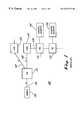
- FIG. 1is a block diagram of a conventional cable television system.
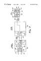
- FIG. 2is an electrical block diagram of conventional headend, hub, and node equipment for use in a cable television system.
- FIG. 3is an electrical block diagram of headend, hub, and node equipment for use in a cable television system in accordance with the present invention.
- FIG. 1shows a communications system, such as a cable television system 100 having both forward and reverse paths, i.e., having the ability to communicate downstream in the forward direction and upstream in the reverse direction.
- the cable television system 100includes headend equipment 105 for receiving signals from various sources and processing and/or modulating them for delivery over the communications network 100 .
- the signalsare then converted to cable television signals that are routed throughout the system 100 to subscriber equipment 140 , such as set top decoders, televisions, or computers, located in the residences or offices of system subscribers.
- the headend 105can, for instance, convert a broadband radio frequency (RF) signal to an optical signal that is transmitted over fiber optic cable 110 , in which case a remotely located optical hub 115 forwards the optical signal further throughout branches of the system 100 over additional fiber optic communication media 120 .
- RFradio frequency
- one or more optical nodes 125convert the forward optical signals to electrical radio frequency (RF) signals for transmission deeper into the system 100 over electrical communication media, such as coaxial cable 130 .
- Taps 135 located along the cable 130 at various points in the distribution systemsplit off portions of the RF signal for routing to subscriber equipment 140 coupled to subscriber drops provided at the taps 135 .
- the system 100also has reverse transmission capability so that signals, such as data, video, or voice signals, generated by the subscriber equipment 140 can be provided back to the headend equipment 105 for processing.
- the reverse signalstravel through the taps 135 and any nodes 125 and hubs 115 to the headend 105 .
- RF signals generated by the subscriber equipment 140travel to the node 125 , which converts the RF signals to optical signals for transmission over the fiber optic cable 120 through the hub 115 to the headend 105 .
- FIG. 2shows an analog reverse path scheme that has been employed in the reverse path of cable television systems, such as the system 100 of FIG. 1 .
- the node 300includes, for example, reverse path equipment for processing upstream signals generated at approximately 1,000 homes. More specifically, the node 300 includes four input ports 205 for receiving RF signals forwarded upstream by taps (not shown) within the system.
- the RF signalsare provided to a signal summer 210 for combining the RF signals, and the summed analog RF signal is provided to an analog optical transmitter 215 for transmission, in a known manner, as an optical signal over a fiber optic communication channel 320 .
- the optical signalcan, for instance, be transmitted at 1310 nanometers (nm).
- An upstream hub 330includes four receiver circuits 230 , each one of which can process an incoming analog optical signal from a different node 300 .
- Each receiver circuit 230processes the received analog optical signal to recover the RF signal which was summed in the node 300 and subsequently provided to the node transmitter 215 .
- the recovered RF signals from the four receiver circuits 230are combined by a signal summer 235 within the hub 330 and then processed for transmission by an analog optical transmitter 240 , which can, for example, transmit at 1550 nm.
- the output of the transmitter 240is provided to an input of a eight-to-one dense wave division multiplexer (DWDM) 250 , which can multiplex the optical signal together with other upstream optical signals.
- DWDMdense wave division multiplexer
- the multiplexed optical signalis then amplified by an optical amplifier/splitter 255 within the hub 330 for transmission over two different fiber optic cables 345 , 350 .
- the four receiver circuits 230 , the summer 235 , and the analog transmitter 240comprise only a single reverse circuit of the hub reverse path circuitry. It will be appreciated that seven other such reverse circuits can be included in the hub 330 for connection to the DWDM 250 , which multiplexes eight incoming signals to provide a single output signal. As a result, the hub 330 can process reverse traffic from 32,000 homes.
- two fiber optic cables 345 , 350are coupled to inputs of reverse circuitry included within headend equipment 360 .
- the reverse path of the headend equipment 360includes an optical switch 270 for switching between the received analog optical signals, which are redundant, into a single signal that is coupled to the input of a one-to-eight DWDM 275 that demultiplexes the optical signal to generate eight optical outputs.
- Each of the eight output signalsis provided to a receiver 280 (only one of which is shown) for recovering the RF signal and providing it at an output buss 310 .
- the headend equipment 360can, therefore, provide reverse signal traffic for up to 4,000 subscribers on each RF buss 310 .
- the reverse path architecture of FIG. 2processes reverse path traffic for up to 32,000 subscribers by transmitting upstream signals in an analog format.
- Each hub within such architecturecontains both forward and reverse circuitry associated with numerous optical nodes served by that hub, and the hubs serve as a collection point for return signals from each node.
- a cable television hubmay be included within a dedicated building or, more typically, within a small cabinet that may or may not be environmentally controlled and in which space is limited. Therefore, cable service providers understandably desire to limit the amount of circuitry that must be included within a hub.
- cable television network reliabilityis of paramount importance, and increasing the number of active components in a device increases the likelihood of mechanical and electrical failure or malfunction. This is even more of a problem in devices, such as hubs, that may not be environmentally controlled, that serve a large number of cable television subscribers, and that may be located in physically distant regions. Security is also an issue, since conventional hubs are distant from a central office and are often located in areas, such as utility easements, that are easily accessible by vandals. For all of these reasons, reduction of complex circuitry at remote locations, such as within hubs and nodes of a cable television architecture, is desirable.
- the analog architecture of FIG. 2is less than ideal not only because of the amount of remotely located complex equipment in the reverse path, but also because the reverse transmissions occur in an analog environment. As a result, all of the problems that are associated with numerous analog transmissions over great distances (detailed in the Background of the Invention hereinabove) are present in the analog architecture of FIG. 2 . Additionally, the architecture of FIG. 2 is bandwidth restrictive because approximately 4,000 homes share a single buss at multiple locations within the reverse path architecture. These problems are mitigated in the reverse path cable television architecture shown in FIG. 3 .
- FIG. 3illustrates reverse path circuitry included in cable television nodes, hubs, and headend equipment of a cable television system in accordance with the present invention.
- an optical node 400includes a reverse path circuit comprising four analog RF input ports 405 for receiving reverse transmissions from subscriber equipment.
- the node 400further includes two or more analog-to-digital (A/D) converters 410 , each of which is coupled to two input ports 405 for receiving two RF signals which are combined (either inside or outside of the A/D converter 410 ) prior to digital conversion. In this manner, RF signals can be received by the node 400 from approximately 1,000 subscribers.
- A/D converters 410analog-to-digital converters
- Each A/D converter 410converts the combined analog electrical signals to a single digital electrical signal that is provided to an input of an N-to-one time division multiplexer 415 , where N can, for example, equal two (2).
- the multiplexer 415interleaves the incoming digital electrical signals, such as by bits, bytes, or data packets, to provide a single digital bit stream which is digitally optically transmitted by an optical transmitter 418 , which can, for instance, transmit over a fiber optic cable 420 at 1550 nm.
- the digital optical signalis received by reverse path circuitry included in the hub 430 and routed directly to an input of an N-to-one DWDM 435 , where N can be eight (8).
- Ncan be eight (8).
- the DWDM 435can also receive seven other digital optical signals from seven other nodes so that the hub 430 is capable of processing reverse signals from a total of 8,000 subscribers.
- the DWDM 435multiplexes the signals to generate a single digital optical output, which can optionally be split by a passive optical splitter 440 into two signals, each of which is transported over a different fiber optic cable 445 , 450 for redundancy. Diversity within the system is not, however, necessary.
- the two fiber optic cables 445 , 450are coupled to reverse path inputs of headend equipment 460 .
- the headend equipment 460includes an optical switch 465 that switches between the two received digital optical signals into a single digital optical signal that is coupled to the input of a one-to-N DWDM 470 , where N can be equal to eight (8).
- Ncan be equal to eight (8).
- the DWDM 470demultiplexes the digital optical signal to generate eight digital optical signals at its eight outputs.
- Each output of the DWDM 470is coupled to a receiver 480 (only one of which is shown) for converting the digital optical signal to a digital electrical signal and then to a time division demultiplexer 490 for splitting the electrical signal into two digital electrical signals that are equivalent to the two digital electrical signals that were previously generated by the A/D converters 410 of the node 400 .
- Each demultiplexed signalis provided to a digital-to-analog (D/A) converter 500 , which converts the digital electrical signal to an analog electrical signal for transmission over an RF buss 510 , 515 .
- D/Adigital-to-analog
- the headend equipment 460can include a receiver, demultiplexer, and two D/A converters for each of the eight DWDM outputs and that, according to the circuitry depicted in FIG. 3, each RF output buss 510 , 515 can provide reverse path transmissions from 500 homes, or subscribers.
- the reverse path architecture of FIG. 3can, according to the present invention, be configured to use different numbers of elements and different types of elements without departing from the teachings herein.
- the node 400could include different numbers of A/D converters 410 , and the time division multiplexing need not be two-to-one.
- the DWDMs 435 , 470could process various numbers of signals, and diversity could be entirely lacking in the reverse path architecture between the hub 430 and the headend 460 .
- a greater number of diverse pathscould be employed, if desired.
- nodes 400 , hubs 430 , and headend equipment 460process signals from a greater number or a lesser number of subscriber homes without impacting the advantages of the reverse path architecture described herein.
- a fiber link digital reverse architectureis employed in conjunction with time division multiplexing to transport multiple reverse bands from an optical node through a simplified hub back to the headend equipment, and the hub can become totally passive in the reverse path.
- the hubis less likely to malfunction and its components can be physically arranged within a smaller space.
- the hubconsequently, can be mounted within a smaller housing that could be aerially mounted so that it is less accessible, which decreases security concerns.
- the reverse path architecture of the present inventioneliminates active reverse electronics in hub sites and significantly reduces the number of node transmitters and headend receivers.
- the node transmitters and headend receiversare reduced by a factor of four when compared to the analog approach of FIG. 2 . Still other advantages are that, since reverse path signals are not received, processed, and retransmitted within the hub, the signal quality is not unnecessarily degraded by such processing and retransmission and, since reverse signals from only 500 homes are processed on each reverse buss, bandwidth is not unnecessarily restricted.
Landscapes
- Engineering & Computer Science (AREA)
- Signal Processing (AREA)
- Computer Networks & Wireless Communication (AREA)
- Multimedia (AREA)
- Two-Way Televisions, Distribution Of Moving Picture Or The Like (AREA)
- Optical Communication System (AREA)
Abstract
Description
Claims (6)
Priority Applications (3)
| Application Number | Priority Date | Filing Date | Title |
|---|---|---|---|
| US09/283,498US6523177B1 (en) | 1999-04-01 | 1999-04-01 | Cable television system with digital reverse path architecture |
| US10/217,886US20030023983A1 (en) | 1999-04-01 | 2002-08-13 | Cable television system with digital reverse path architecture |
| US10/277,408US20030056227A1 (en) | 1999-04-01 | 2002-10-22 | Cable television system with digital reverse path architecture |
Applications Claiming Priority (1)
| Application Number | Priority Date | Filing Date | Title |
|---|---|---|---|
| US09/283,498US6523177B1 (en) | 1999-04-01 | 1999-04-01 | Cable television system with digital reverse path architecture |
Related Child Applications (2)
| Application Number | Title | Priority Date | Filing Date |
|---|---|---|---|
| US10/217,886Continuation-In-PartUS20030023983A1 (en) | 1999-04-01 | 2002-08-13 | Cable television system with digital reverse path architecture |
| US10/277,408ContinuationUS20030056227A1 (en) | 1999-04-01 | 2002-10-22 | Cable television system with digital reverse path architecture |
Publications (1)
| Publication Number | Publication Date |
|---|---|
| US6523177B1true US6523177B1 (en) | 2003-02-18 |
Family
ID=23086345
Family Applications (2)
| Application Number | Title | Priority Date | Filing Date |
|---|---|---|---|
| US09/283,498Expired - LifetimeUS6523177B1 (en) | 1999-04-01 | 1999-04-01 | Cable television system with digital reverse path architecture |
| US10/277,408AbandonedUS20030056227A1 (en) | 1999-04-01 | 2002-10-22 | Cable television system with digital reverse path architecture |
Family Applications After (1)
| Application Number | Title | Priority Date | Filing Date |
|---|---|---|---|
| US10/277,408AbandonedUS20030056227A1 (en) | 1999-04-01 | 2002-10-22 | Cable television system with digital reverse path architecture |
Country Status (1)
| Country | Link |
|---|---|
| US (2) | US6523177B1 (en) |
Cited By (41)
| Publication number | Priority date | Publication date | Assignee | Title |
|---|---|---|---|---|
| US20020003640A1 (en)* | 1999-09-03 | 2002-01-10 | Trezza John A. | Star topology network with fiber interconnect on chip |
| US20020010942A1 (en)* | 2000-02-29 | 2002-01-24 | Howald Robert L. | Application of digital processing scheme for enhanced cable television network performance |
| US20020129379A1 (en)* | 1999-12-13 | 2002-09-12 | Levinson Frank H. | System and method for transmitting data on return path of a cable television system |
| US20020157114A1 (en)* | 2001-04-23 | 2002-10-24 | Mobley J. Graham | Burst-mode digital transmitter |
| US20020188953A1 (en)* | 2001-06-06 | 2002-12-12 | Kevin Kenworthy | Centralized aggregation of broadcast television programming and multi-market digital delivery thereof over interconnected terrestrial fiber optic networks |
| US20030056227A1 (en)* | 1999-04-01 | 2003-03-20 | Farhan Fariborz M. | Cable television system with digital reverse path architecture |
| US20030110509A1 (en)* | 1999-12-13 | 2003-06-12 | Levinson Frank H. | Cable television return link system with high data-rate side-band communication channels |
| US20030113158A1 (en)* | 2001-12-14 | 2003-06-19 | Compaq Information Technologies Group, L.P. | Technique for providing a pivot structure that faciliates the rapid formation of pivot couplings between components |
| US20030154498A1 (en)* | 2002-02-12 | 2003-08-14 | Sage Gerald F. | Efficient transmission of digital return path data in cable television return path |
| US20030154494A1 (en)* | 2002-02-08 | 2003-08-14 | Sage Gerald Francis | Bandpass component decimation and transmission of data in cable television digital return path |
| US20030154495A1 (en)* | 2002-02-12 | 2003-08-14 | Finisar Corporation | Data rate compression device for cable television return path using bandpass puncturing |
| US20030156602A1 (en)* | 2002-02-19 | 2003-08-21 | Sage Gerald F. | Asynchronous digital signal combiner and method of combining asynchronous digital signals in cable television return path |
| US20040103441A1 (en)* | 2002-10-30 | 2004-05-27 | Williams Andrew R. | Return path transmitter with extended digital processing circuitry |
| US20040103440A1 (en)* | 2002-11-25 | 2004-05-27 | General Instrument Corporation | Transmitter in a digital return link for use in an HFC network |
| US20040208572A1 (en)* | 2001-12-27 | 2004-10-21 | Koninklijke Philips Electronics N.W. | WDM optical transmission system with passive hub |
| US20050254523A1 (en)* | 2004-05-12 | 2005-11-17 | Oyadomari Randy I | Automated ethernet configuration of CATV network |
| US20050262545A1 (en)* | 2002-05-15 | 2005-11-24 | Kouichi Masuda | CATV uplink optical transmission system |
| US20050273836A1 (en)* | 2004-05-12 | 2005-12-08 | Oyadomari Randy I | Changing communication mode in a CATV pathway using mute commands |
| US20050273837A1 (en)* | 2004-05-12 | 2005-12-08 | Oyadomari Randy I | Single master clock control of ethernet data transfer over both a cable TV return path and an ethernet forward path |
| US20060165413A1 (en)* | 1999-05-24 | 2006-07-27 | Broadband Royalty Corporation | DWDM CATV return system with up-converters to prevent fiber crosstalk |
| US7190903B1 (en)* | 1999-02-17 | 2007-03-13 | At&T Corp. | Fiber and wire communication system |
| US7283749B1 (en) | 1999-02-17 | 2007-10-16 | At&T Corp. | Fiber and wire communication system |
| US7519297B2 (en) | 2002-11-08 | 2009-04-14 | Finisar Corporation | Cable television system with separate radio frequency hub and ethernet hub |
| US20090119735A1 (en)* | 2000-10-16 | 2009-05-07 | Oleg Dounaevski | Wideband node in a catv network |
| US7725036B2 (en) | 2002-02-12 | 2010-05-25 | Finisar Corporation | Efficient transmission of digital return path data in cable television return path |
| US7734179B1 (en) | 1999-02-17 | 2010-06-08 | At&T Corp. | Fiber/wired communication system |
| US20100209058A1 (en)* | 2007-06-18 | 2010-08-19 | Ott Michael J | Fiber optic telecommunications system |
| US20120057877A1 (en)* | 2003-03-14 | 2012-03-08 | Enablence Usa Fttx Networks Inc. | Method and system for providing a return path for signals generated by legacy terminals in an optical network |
| US8554076B1 (en)* | 1999-10-04 | 2013-10-08 | At&T Intellectual Property Ii, L.P. | Methods and systems for constructing optical networks |
| US8670667B1 (en)* | 2008-11-19 | 2014-03-11 | Adtran, Inc. | Access multiplexers and methods for multiplexing telecommunication signals using an arrayed media converter |
| US9037143B2 (en) | 2010-08-16 | 2015-05-19 | Corning Optical Communications LLC | Remote antenna clusters and related systems, components, and methods supporting digital data signal propagation between remote antenna units |
| US9042732B2 (en) | 2010-05-02 | 2015-05-26 | Corning Optical Communications LLC | Providing digital data services in optical fiber-based distributed radio frequency (RF) communication systems, and related components and methods |
| US9325429B2 (en) | 2011-02-21 | 2016-04-26 | Corning Optical Communications LLC | Providing digital data services as electrical signals and radio-frequency (RF) communications over optical fiber in distributed communications systems, and related components and methods |
| US9525488B2 (en) | 2010-05-02 | 2016-12-20 | Corning Optical Communications LLC | Digital data services and/or power distribution in optical fiber-based distributed communications systems providing digital data and radio frequency (RF) communications services, and related components and methods |
| US10096909B2 (en) | 2014-11-03 | 2018-10-09 | Corning Optical Communications Wireless Ltd. | Multi-band monopole planar antennas configured to facilitate improved radio frequency (RF) isolation in multiple-input multiple-output (MIMO) antenna arrangement |
| US10110308B2 (en) | 2014-12-18 | 2018-10-23 | Corning Optical Communications Wireless Ltd | Digital interface modules (DIMs) for flexibly distributing digital and/or analog communications signals in wide-area analog distributed antenna systems (DASs) |
| US10135533B2 (en) | 2014-11-13 | 2018-11-20 | Corning Optical Communications Wireless Ltd | Analog distributed antenna systems (DASS) supporting distribution of digital communications signals interfaced from a digital signal source and analog radio frequency (RF) communications signals |
| US10187151B2 (en) | 2014-12-18 | 2019-01-22 | Corning Optical Communications Wireless Ltd | Digital-analog interface modules (DAIMs) for flexibly distributing digital and/or analog communications signals in wide-area analog distributed antenna systems (DASs) |
| US10659163B2 (en) | 2014-09-25 | 2020-05-19 | Corning Optical Communications LLC | Supporting analog remote antenna units (RAUs) in digital distributed antenna systems (DASs) using analog RAU digital adaptors |
| US11178609B2 (en) | 2010-10-13 | 2021-11-16 | Corning Optical Communications LLC | Power management for remote antenna units in distributed antenna systems |
| US11750415B1 (en)* | 2019-01-21 | 2023-09-05 | Harmonic, Inc. | Remote PHY narrowband digital return (NDR) |
Families Citing this family (1)
| Publication number | Priority date | Publication date | Assignee | Title |
|---|---|---|---|---|
| US7085495B2 (en)* | 2000-08-03 | 2006-08-01 | At&T Corp. | System for flexible multiple broadcast service delivery over a WDM passive optical network based on RF block-conversion of RF service bands within wavelength bands |
Citations (17)
| Publication number | Priority date | Publication date | Assignee | Title |
|---|---|---|---|---|
| US3995120A (en) | 1975-05-30 | 1976-11-30 | Gte Automatic Electric Laboratories Incorporated | Digital time-division multiplexing system |
| US4759018A (en) | 1985-06-17 | 1988-07-19 | At&T Bell Laboratories | Higher order digital transmission system including a multiplexer and a demultiplexer |
| US4994909A (en)* | 1989-05-04 | 1991-02-19 | Northern Telecom Limited | Video signal distribution system |
| US5018142A (en) | 1988-03-04 | 1991-05-21 | Digital Equipment Corporation | Technique for organizing and coding serial binary data from a plurality of data lines for transmission over a single transmission line |
| US5221983A (en)* | 1989-01-19 | 1993-06-22 | Bell Communications Research, Inc. | Passive photonic loop architecture employing wavelength multiplexing |
| US5420583A (en) | 1991-11-06 | 1995-05-30 | Cray Research, Inc. | Fiber optic channel extender interface method and apparatus |
| US5488413A (en)* | 1994-06-14 | 1996-01-30 | Xel Communications, Inc. | CATV telephony system using subsplit band for both directions of transmission |
| US5563815A (en) | 1993-08-30 | 1996-10-08 | Fostex Research & Development, Inc. | Digital tone oscillator for certain exact frequencies and method for generating tones |
| US5819036A (en)* | 1995-12-14 | 1998-10-06 | Time Warner Cable | Method for message addressing in a full service network |
| US5822677A (en)* | 1996-08-26 | 1998-10-13 | At&T Corp. | Shared hybrid-fiber coax transmission system having increased bandwidth in the upstream and downstream directions |
| US5854703A (en)* | 1997-02-28 | 1998-12-29 | Scientific-Atlanta, Inc. | Hybrid fiber coax communications network |
| US5862451A (en)* | 1996-01-22 | 1999-01-19 | Motorola, Inc. | Channel quality management in a cable telephony system |
| US5864748A (en)* | 1996-09-18 | 1999-01-26 | At&T Corp. | Hybrid fiber-coax system having at least one digital fiber node and increased upstream and downstream bandwidth |
| US5878325A (en)* | 1996-07-12 | 1999-03-02 | At&T Corp | Hybrid fiber-coax system having at least one digital fiber node |
| US5969836A (en)* | 1997-12-12 | 1999-10-19 | Alcatel Usa Sourcing, L.P. | Method and apparatus for simultaneous transmission of digital telephony and analog video over a single optic fiber using wave division multiplexing |
| US6147786A (en)* | 1998-02-20 | 2000-11-14 | Nokia Telecommunications, Oy | Hybrid analog/digital WDM access network with mini-digital optical node |
| US6317234B1 (en)* | 1997-11-04 | 2001-11-13 | British Telecommunications Public Limited Company | Communications network |
Family Cites Families (11)
| Publication number | Priority date | Publication date | Assignee | Title |
|---|---|---|---|---|
| US5426527A (en)* | 1991-11-12 | 1995-06-20 | Alliant Techsystems Inc. | System for transmitting multiple signals across a single fiber optic channel |
| US5627879A (en)* | 1992-09-17 | 1997-05-06 | Adc Telecommunications, Inc. | Cellular communications system with centralized base stations and distributed antenna units |
| CA2118616C (en)* | 1993-03-11 | 1999-09-14 | Thomas Edward Darcie | Optical network based on remote interrogation of terminal equipment |
| US5579308A (en)* | 1995-11-22 | 1996-11-26 | Samsung Electronics, Ltd. | Crossbar/hub arrangement for multimedia network |
| US5694232A (en)* | 1995-12-06 | 1997-12-02 | Ericsson Raynet | Full duplex optical modem for broadband access network |
| US5808764A (en)* | 1995-12-28 | 1998-09-15 | Lucent Technologies, Inc. | Multiple star, passive optical network based on remote interrogation of terminal equipment |
| US5915205A (en)* | 1996-01-19 | 1999-06-22 | Texas Instruments Incorporated | Ingress noise cancellation for upstream signals on a cable television system using an antenna to determine local noise |
| US6538781B1 (en)* | 1997-02-25 | 2003-03-25 | John Beierle | Multimedia distribution system using fiber optic lines |
| US6373611B1 (en)* | 1998-06-22 | 2002-04-16 | Scientific-Atlanta, Inc. | Digital optical transmitter |
| US6567987B1 (en)* | 1999-02-16 | 2003-05-20 | Scientific-Atlanta, Inc. | Digital optical transmitter with improved noise power ratio |
| US6523177B1 (en)* | 1999-04-01 | 2003-02-18 | Scientific-Atlanta, Inc. | Cable television system with digital reverse path architecture |
- 1999
- 1999-04-01USUS09/283,498patent/US6523177B1/ennot_activeExpired - Lifetime
- 2002
- 2002-10-22USUS10/277,408patent/US20030056227A1/ennot_activeAbandoned
Patent Citations (17)
| Publication number | Priority date | Publication date | Assignee | Title |
|---|---|---|---|---|
| US3995120A (en) | 1975-05-30 | 1976-11-30 | Gte Automatic Electric Laboratories Incorporated | Digital time-division multiplexing system |
| US4759018A (en) | 1985-06-17 | 1988-07-19 | At&T Bell Laboratories | Higher order digital transmission system including a multiplexer and a demultiplexer |
| US5018142A (en) | 1988-03-04 | 1991-05-21 | Digital Equipment Corporation | Technique for organizing and coding serial binary data from a plurality of data lines for transmission over a single transmission line |
| US5221983A (en)* | 1989-01-19 | 1993-06-22 | Bell Communications Research, Inc. | Passive photonic loop architecture employing wavelength multiplexing |
| US4994909A (en)* | 1989-05-04 | 1991-02-19 | Northern Telecom Limited | Video signal distribution system |
| US5420583A (en) | 1991-11-06 | 1995-05-30 | Cray Research, Inc. | Fiber optic channel extender interface method and apparatus |
| US5563815A (en) | 1993-08-30 | 1996-10-08 | Fostex Research & Development, Inc. | Digital tone oscillator for certain exact frequencies and method for generating tones |
| US5488413A (en)* | 1994-06-14 | 1996-01-30 | Xel Communications, Inc. | CATV telephony system using subsplit band for both directions of transmission |
| US5819036A (en)* | 1995-12-14 | 1998-10-06 | Time Warner Cable | Method for message addressing in a full service network |
| US5862451A (en)* | 1996-01-22 | 1999-01-19 | Motorola, Inc. | Channel quality management in a cable telephony system |
| US5878325A (en)* | 1996-07-12 | 1999-03-02 | At&T Corp | Hybrid fiber-coax system having at least one digital fiber node |
| US5822677A (en)* | 1996-08-26 | 1998-10-13 | At&T Corp. | Shared hybrid-fiber coax transmission system having increased bandwidth in the upstream and downstream directions |
| US5864748A (en)* | 1996-09-18 | 1999-01-26 | At&T Corp. | Hybrid fiber-coax system having at least one digital fiber node and increased upstream and downstream bandwidth |
| US5854703A (en)* | 1997-02-28 | 1998-12-29 | Scientific-Atlanta, Inc. | Hybrid fiber coax communications network |
| US6317234B1 (en)* | 1997-11-04 | 2001-11-13 | British Telecommunications Public Limited Company | Communications network |
| US5969836A (en)* | 1997-12-12 | 1999-10-19 | Alcatel Usa Sourcing, L.P. | Method and apparatus for simultaneous transmission of digital telephony and analog video over a single optic fiber using wave division multiplexing |
| US6147786A (en)* | 1998-02-20 | 2000-11-14 | Nokia Telecommunications, Oy | Hybrid analog/digital WDM access network with mini-digital optical node |
Cited By (76)
| Publication number | Priority date | Publication date | Assignee | Title |
|---|---|---|---|---|
| US20090067841A1 (en)* | 1999-02-17 | 2009-03-12 | Combs Charles D | Fiber and wire communication system |
| US7783196B2 (en) | 1999-02-17 | 2010-08-24 | At&T Intellectual Property Ii, L.P. | Fiber and wire communication system |
| US20080019695A1 (en)* | 1999-02-17 | 2008-01-24 | Combs Charles D | Fiber and wire communication system |
| US7283749B1 (en) | 1999-02-17 | 2007-10-16 | At&T Corp. | Fiber and wire communication system |
| US20070166036A1 (en)* | 1999-02-17 | 2007-07-19 | Combs Charles D | Fiber and wire communication system |
| US7190903B1 (en)* | 1999-02-17 | 2007-03-13 | At&T Corp. | Fiber and wire communication system |
| US7831147B2 (en) | 1999-02-17 | 2010-11-09 | At&T Intellectual Property Ii, L.P. | Fiber and wire communication system |
| US7734179B1 (en) | 1999-02-17 | 2010-06-08 | At&T Corp. | Fiber/wired communication system |
| US7450850B2 (en) | 1999-02-17 | 2008-11-11 | At&T Corp. | Fiber and wire communication system |
| US20030056227A1 (en)* | 1999-04-01 | 2003-03-20 | Farhan Fariborz M. | Cable television system with digital reverse path architecture |
| US20060165413A1 (en)* | 1999-05-24 | 2006-07-27 | Broadband Royalty Corporation | DWDM CATV return system with up-converters to prevent fiber crosstalk |
| US20020003640A1 (en)* | 1999-09-03 | 2002-01-10 | Trezza John A. | Star topology network with fiber interconnect on chip |
| US6889010B2 (en)* | 1999-09-03 | 2005-05-03 | Altera Corporation | Star topology network with fiber interconnect on chip |
| US8554076B1 (en)* | 1999-10-04 | 2013-10-08 | At&T Intellectual Property Ii, L.P. | Methods and systems for constructing optical networks |
| US7222358B2 (en) | 1999-12-13 | 2007-05-22 | Finisar Corporation | Cable television return link system with high data-rate side-band communication channels |
| US20030110509A1 (en)* | 1999-12-13 | 2003-06-12 | Levinson Frank H. | Cable television return link system with high data-rate side-band communication channels |
| US7778554B2 (en) | 1999-12-13 | 2010-08-17 | Finisar Corporation | System and method for transmitting data on return path of a cable television system |
| US7529487B2 (en) | 1999-12-13 | 2009-05-05 | Finisar Corporation | System and method for transmitting data on return path of a cable television system |
| US20080019706A1 (en)* | 1999-12-13 | 2008-01-24 | Finisar Corporation | System and method for transmitting data on return path of a cable television system |
| US20020129379A1 (en)* | 1999-12-13 | 2002-09-12 | Levinson Frank H. | System and method for transmitting data on return path of a cable television system |
| US7257328B2 (en) | 1999-12-13 | 2007-08-14 | Finisar Corporation | System and method for transmitting data on return path of a cable television system |
| US20020010942A1 (en)* | 2000-02-29 | 2002-01-24 | Howald Robert L. | Application of digital processing scheme for enhanced cable television network performance |
| US7904932B2 (en)* | 2000-10-16 | 2011-03-08 | Xtend Networks Ltd. | Wideband node in a CATV network |
| US20090119735A1 (en)* | 2000-10-16 | 2009-05-07 | Oleg Dounaevski | Wideband node in a catv network |
| US20020157114A1 (en)* | 2001-04-23 | 2002-10-24 | Mobley J. Graham | Burst-mode digital transmitter |
| US20020188953A1 (en)* | 2001-06-06 | 2002-12-12 | Kevin Kenworthy | Centralized aggregation of broadcast television programming and multi-market digital delivery thereof over interconnected terrestrial fiber optic networks |
| US6718553B2 (en)* | 2001-06-06 | 2004-04-06 | Complete Tv Llc | Centralized aggregation of broadcast television programming and multi-market digital delivery thereof over interconnected terrestrial fiber optic networks |
| US20040255333A1 (en)* | 2001-06-06 | 2004-12-16 | Kevin Kenworthy | Centralized aggregation of broadcast television programming and multi-market digital delivery thereof over interconnected terrestrial fiber optic networks |
| US20030113158A1 (en)* | 2001-12-14 | 2003-06-19 | Compaq Information Technologies Group, L.P. | Technique for providing a pivot structure that faciliates the rapid formation of pivot couplings between components |
| US20040208572A1 (en)* | 2001-12-27 | 2004-10-21 | Koninklijke Philips Electronics N.W. | WDM optical transmission system with passive hub |
| US20030154494A1 (en)* | 2002-02-08 | 2003-08-14 | Sage Gerald Francis | Bandpass component decimation and transmission of data in cable television digital return path |
| US7971225B2 (en) | 2002-02-08 | 2011-06-28 | Finisar Corporation | Bandpass component decimation and transmission of data in cable television digital return path |
| US8156535B2 (en) | 2002-02-12 | 2012-04-10 | Finsar Corporation | Data rate compression device for cable television return path using bandpass puncturing |
| US20030154498A1 (en)* | 2002-02-12 | 2003-08-14 | Sage Gerald F. | Efficient transmission of digital return path data in cable television return path |
| US20030154495A1 (en)* | 2002-02-12 | 2003-08-14 | Finisar Corporation | Data rate compression device for cable television return path using bandpass puncturing |
| US7725036B2 (en) | 2002-02-12 | 2010-05-25 | Finisar Corporation | Efficient transmission of digital return path data in cable television return path |
| US7751718B2 (en) | 2002-02-12 | 2010-07-06 | Finisar Corporation | Efficient transmission of digital return path data in cable television return path |
| US7359447B2 (en) | 2002-02-19 | 2008-04-15 | Finisar Corporation | Asynchronous digital signal combiner and method of combining asynchronous digital signals in cable television return path |
| US20030156602A1 (en)* | 2002-02-19 | 2003-08-21 | Sage Gerald F. | Asynchronous digital signal combiner and method of combining asynchronous digital signals in cable television return path |
| US20050262545A1 (en)* | 2002-05-15 | 2005-11-24 | Kouichi Masuda | CATV uplink optical transmission system |
| US7603693B2 (en)* | 2002-05-15 | 2009-10-13 | Panasonic Corporation | CATV uplink optical transmission system |
| US20040103441A1 (en)* | 2002-10-30 | 2004-05-27 | Williams Andrew R. | Return path transmitter with extended digital processing circuitry |
| US7519297B2 (en) | 2002-11-08 | 2009-04-14 | Finisar Corporation | Cable television system with separate radio frequency hub and ethernet hub |
| US20040103440A1 (en)* | 2002-11-25 | 2004-05-27 | General Instrument Corporation | Transmitter in a digital return link for use in an HFC network |
| US20120057877A1 (en)* | 2003-03-14 | 2012-03-08 | Enablence Usa Fttx Networks Inc. | Method and system for providing a return path for signals generated by legacy terminals in an optical network |
| US8682162B2 (en)* | 2003-03-14 | 2014-03-25 | Aurora Networks, Inc. | Method and system for providing a return path for signals generated by legacy terminals in an optical network |
| US20050254523A1 (en)* | 2004-05-12 | 2005-11-17 | Oyadomari Randy I | Automated ethernet configuration of CATV network |
| US8032916B2 (en) | 2004-05-12 | 2011-10-04 | Finisar Corporation | Single master clock control of Ethernet data transfer over both a cable TV return path and an Ethernet forward path |
| US7765576B2 (en) | 2004-05-12 | 2010-07-27 | Finsiar Corporation | Changing communication mode in a CATV pathway using mute commands |
| US7519078B2 (en) | 2004-05-12 | 2009-04-14 | Finisar Corporation | Automated ethernet configuration of CATV network |
| US20050273837A1 (en)* | 2004-05-12 | 2005-12-08 | Oyadomari Randy I | Single master clock control of ethernet data transfer over both a cable TV return path and an ethernet forward path |
| US20050273836A1 (en)* | 2004-05-12 | 2005-12-08 | Oyadomari Randy I | Changing communication mode in a CATV pathway using mute commands |
| US20100209058A1 (en)* | 2007-06-18 | 2010-08-19 | Ott Michael J | Fiber optic telecommunications system |
| US8670667B1 (en)* | 2008-11-19 | 2014-03-11 | Adtran, Inc. | Access multiplexers and methods for multiplexing telecommunication signals using an arrayed media converter |
| US9525488B2 (en) | 2010-05-02 | 2016-12-20 | Corning Optical Communications LLC | Digital data services and/or power distribution in optical fiber-based distributed communications systems providing digital data and radio frequency (RF) communications services, and related components and methods |
| US9042732B2 (en) | 2010-05-02 | 2015-05-26 | Corning Optical Communications LLC | Providing digital data services in optical fiber-based distributed radio frequency (RF) communication systems, and related components and methods |
| US9270374B2 (en) | 2010-05-02 | 2016-02-23 | Corning Optical Communications LLC | Providing digital data services in optical fiber-based distributed radio frequency (RF) communications systems, and related components and methods |
| US9853732B2 (en) | 2010-05-02 | 2017-12-26 | Corning Optical Communications LLC | Digital data services and/or power distribution in optical fiber-based distributed communications systems providing digital data and radio frequency (RF) communications services, and related components and methods |
| US10014944B2 (en) | 2010-08-16 | 2018-07-03 | Corning Optical Communications LLC | Remote antenna clusters and related systems, components, and methods supporting digital data signal propagation between remote antenna units |
| US9037143B2 (en) | 2010-08-16 | 2015-05-19 | Corning Optical Communications LLC | Remote antenna clusters and related systems, components, and methods supporting digital data signal propagation between remote antenna units |
| US11178609B2 (en) | 2010-10-13 | 2021-11-16 | Corning Optical Communications LLC | Power management for remote antenna units in distributed antenna systems |
| US11671914B2 (en) | 2010-10-13 | 2023-06-06 | Corning Optical Communications LLC | Power management for remote antenna units in distributed antenna systems |
| US11224014B2 (en) | 2010-10-13 | 2022-01-11 | Corning Optical Communications LLC | Power management for remote antenna units in distributed antenna systems |
| US11212745B2 (en) | 2010-10-13 | 2021-12-28 | Corning Optical Communications LLC | Power management for remote antenna units in distributed antenna systems |
| US9325429B2 (en) | 2011-02-21 | 2016-04-26 | Corning Optical Communications LLC | Providing digital data services as electrical signals and radio-frequency (RF) communications over optical fiber in distributed communications systems, and related components and methods |
| US9813164B2 (en) | 2011-02-21 | 2017-11-07 | Corning Optical Communications LLC | Providing digital data services as electrical signals and radio-frequency (RF) communications over optical fiber in distributed communications systems, and related components and methods |
| US10205538B2 (en) | 2011-02-21 | 2019-02-12 | Corning Optical Communications LLC | Providing digital data services as electrical signals and radio-frequency (RF) communications over optical fiber in distributed communications systems, and related components and methods |
| US10659163B2 (en) | 2014-09-25 | 2020-05-19 | Corning Optical Communications LLC | Supporting analog remote antenna units (RAUs) in digital distributed antenna systems (DASs) using analog RAU digital adaptors |
| US10096909B2 (en) | 2014-11-03 | 2018-10-09 | Corning Optical Communications Wireless Ltd. | Multi-band monopole planar antennas configured to facilitate improved radio frequency (RF) isolation in multiple-input multiple-output (MIMO) antenna arrangement |
| US10135533B2 (en) | 2014-11-13 | 2018-11-20 | Corning Optical Communications Wireless Ltd | Analog distributed antenna systems (DASS) supporting distribution of digital communications signals interfaced from a digital signal source and analog radio frequency (RF) communications signals |
| US10523326B2 (en) | 2014-11-13 | 2019-12-31 | Corning Optical Communications LLC | Analog distributed antenna systems (DASS) supporting distribution of digital communications signals interfaced from a digital signal source and analog radio frequency (RF) communications signals |
| US10110308B2 (en) | 2014-12-18 | 2018-10-23 | Corning Optical Communications Wireless Ltd | Digital interface modules (DIMs) for flexibly distributing digital and/or analog communications signals in wide-area analog distributed antenna systems (DASs) |
| US10523327B2 (en) | 2014-12-18 | 2019-12-31 | Corning Optical Communications LLC | Digital-analog interface modules (DAIMs) for flexibly distributing digital and/or analog communications signals in wide-area analog distributed antenna systems (DASs) |
| US10361783B2 (en) | 2014-12-18 | 2019-07-23 | Corning Optical Communications LLC | Digital interface modules (DIMs) for flexibly distributing digital and/or analog communications signals in wide-area analog distributed antenna systems (DASs) |
| US10187151B2 (en) | 2014-12-18 | 2019-01-22 | Corning Optical Communications Wireless Ltd | Digital-analog interface modules (DAIMs) for flexibly distributing digital and/or analog communications signals in wide-area analog distributed antenna systems (DASs) |
| US11750415B1 (en)* | 2019-01-21 | 2023-09-05 | Harmonic, Inc. | Remote PHY narrowband digital return (NDR) |
Also Published As
| Publication number | Publication date |
|---|---|
| US20030056227A1 (en) | 2003-03-20 |
Similar Documents
| Publication | Publication Date | Title |
|---|---|---|
| US6523177B1 (en) | Cable television system with digital reverse path architecture | |
| US6356369B1 (en) | Digital optical transmitter for processing externally generated information in the reverse path | |
| EP0873638B1 (en) | Hybrid fiber coax communications system | |
| US7266265B2 (en) | Low-loss shared FTTH distribution network | |
| US5861966A (en) | Broad band optical fiber telecommunications network | |
| JP4520643B2 (en) | Optical communication network using frequency division multiplexing | |
| US5864748A (en) | Hybrid fiber-coax system having at least one digital fiber node and increased upstream and downstream bandwidth | |
| US7362931B2 (en) | Optical conversion device for shared FTTH distribution network | |
| CA2219006C (en) | Network apparatus and method to provide compressed digital video over mini-fiber nodes | |
| US7035504B2 (en) | Deep fiber network with high speed data and video on demand | |
| EP1387511B1 (en) | Broadcast/communication unified passive optical network system | |
| US20050074241A1 (en) | System and method for communicating optical signals between a data service provider and subscribers | |
| AU692455B2 (en) | Optical fibre communications system | |
| MX2007016142A (en) | Demodulated digital upstream transmission. | |
| US20030023983A1 (en) | Cable television system with digital reverse path architecture | |
| US7725029B1 (en) | Technique for asymmetric transport | |
| US7197205B1 (en) | Deep fiber network with high speed data and video on demand | |
| US20030063847A1 (en) | Deep fiber network architecture | |
| US6822972B1 (en) | Bidirectional communication system with ring configuration | |
| WO1995005041A1 (en) | Optical fibre communications system | |
| US20030030871A1 (en) | Diversley routed fault tolerant optical node | |
| WO2001095525A2 (en) | Optical modules for redundancy in a broadband communication system | |
| JP2001077795A (en) | Optical communication system for optically combining both of base band signal and pass band signal | |
| EP1384283B1 (en) | Hybrid fibre/coaxial system with reverse path optical combining using an optical commutator | |
| Dobrev et al. | INCREASING OF THE CATV SYSTEM CAPACITY |
Legal Events
| Date | Code | Title | Description |
|---|---|---|---|
| AS | Assignment | Owner name:SCIENTIFIC-ATLANTA, INC., GEORGIA Free format text:ASSIGNMENT OF ASSIGNORS INTEREST;ASSIGNOR:BROWN, DOUGLAS E.;REEL/FRAME:009878/0318 Effective date:19990401 | |
| AS | Assignment | Owner name:SCIENTIFIC-ATLANTA, INC., GEORGIA Free format text:ASSIGNMENT OF ASSIGNORS INTEREST;ASSIGNOR:FARHAN, FARIBORZ M.;REEL/FRAME:013104/0271 Effective date:20020625 | |
| STCF | Information on status: patent grant | Free format text:PATENTED CASE | |
| CC | Certificate of correction | ||
| FPAY | Fee payment | Year of fee payment:4 | |
| FPAY | Fee payment | Year of fee payment:8 | |
| FPAY | Fee payment | Year of fee payment:12 | |
| AS | Assignment | Owner name:SCIENTIFIC-ATLANTA, LLC, GEORGIA Free format text:CHANGE OF NAME;ASSIGNOR:SCIENTIFIC-ATLANTA, INC.;REEL/FRAME:034299/0440 Effective date:20081205 Owner name:CISCO TECHNOLOGY, INC., CALIFORNIA Free format text:ASSIGNMENT OF ASSIGNORS INTEREST;ASSIGNOR:SCIENTIFIC-ATLANTA, LLC;REEL/FRAME:034300/0001 Effective date:20141118 |