US6522826B2 - System and method of winding a fog coil - Google Patents
System and method of winding a fog coilDownload PDFInfo
- Publication number
- US6522826B2 US6522826B2US10/003,914US391401AUS6522826B2US 6522826 B2US6522826 B2US 6522826B2US 391401 AUS391401 AUS 391401AUS 6522826 B2US6522826 B2US 6522826B2
- Authority
- US
- United States
- Prior art keywords
- section
- optical fiber
- fiber
- bobbin
- epoxy
- Prior art date
- Legal status (The legal status is an assumption and is not a legal conclusion. Google has not performed a legal analysis and makes no representation as to the accuracy of the status listed.)
- Expired - Lifetime
Links
- 238000000034methodMethods0.000titleclaimsdescription34
- 238000004804windingMethods0.000titleclaimsdescription24
- 239000013307optical fiberSubstances0.000claimsabstractdescription240
- 239000000835fiberSubstances0.000claimsabstractdescription190
- 239000004593EpoxySubstances0.000claimsabstractdescription116
- 230000003287optical effectEffects0.000claimsdescription25
- 239000011248coating agentSubstances0.000claimsdescription3
- 238000000576coating methodMethods0.000claimsdescription3
- 238000005520cutting processMethods0.000claimsdescription2
- 238000005304joiningMethods0.000claimsdescription2
- 229920006334epoxy coatingPolymers0.000description6
- 238000000059patterningMethods0.000description5
- 239000000758substrateSubstances0.000description4
- 239000000853adhesiveSubstances0.000description3
- 230000001070adhesive effectEffects0.000description3
- 230000005540biological transmissionEffects0.000description3
- 230000015572biosynthetic processEffects0.000description3
- 230000008878couplingEffects0.000description3
- 238000010168coupling processMethods0.000description3
- 238000005859coupling reactionMethods0.000description3
- 238000005516engineering processMethods0.000description3
- 125000003700epoxy groupChemical group0.000description3
- 230000033001locomotionEffects0.000description3
- 238000012856packingMethods0.000description3
- 230000010363phase shiftEffects0.000description3
- 229920000647polyepoxidePolymers0.000description3
- 238000013461designMethods0.000description2
- 230000000694effectsEffects0.000description2
- 239000000463materialSubstances0.000description2
- 230000007246mechanismEffects0.000description2
- 239000002245particleSubstances0.000description2
- 229910003327LiNbO3Inorganic materials0.000description1
- 230000001133accelerationEffects0.000description1
- 230000009471actionEffects0.000description1
- 238000004026adhesive bondingMethods0.000description1
- 230000002411adverseEffects0.000description1
- 238000013459approachMethods0.000description1
- 230000000712assemblyEffects0.000description1
- 238000000429assemblyMethods0.000description1
- 238000005452bendingMethods0.000description1
- 230000008901benefitEffects0.000description1
- 239000002131composite materialSubstances0.000description1
- 238000007796conventional methodMethods0.000description1
- 238000013016dampingMethods0.000description1
- 238000001514detection methodMethods0.000description1
- 238000010586diagramMethods0.000description1
- -1e.g.Substances0.000description1
- 230000007613environmental effectEffects0.000description1
- 230000006353environmental stressEffects0.000description1
- 239000003292glueSubstances0.000description1
- 230000005484gravityEffects0.000description1
- 238000003780insertionMethods0.000description1
- 230000037431insertionEffects0.000description1
- 230000010354integrationEffects0.000description1
- GQYHUHYESMUTHG-UHFFFAOYSA-Nlithium niobateChemical compound[Li+].[O-][Nb](=O)=OGQYHUHYESMUTHG-UHFFFAOYSA-N0.000description1
- 238000004519manufacturing processMethods0.000description1
- 230000008569processEffects0.000description1
- 230000008439repair processEffects0.000description1
- 230000003362replicative effectEffects0.000description1
- 238000011160researchMethods0.000description1
- 239000004065semiconductorSubstances0.000description1
- 230000035945sensitivityEffects0.000description1
- 230000035939shockEffects0.000description1
- 238000005476solderingMethods0.000description1
- 230000000087stabilizing effectEffects0.000description1
- 238000003860storageMethods0.000description1
- 230000035882stressEffects0.000description1
- 238000012360testing methodMethods0.000description1
- 238000009966trimmingMethods0.000description1
Images


Classifications
- G—PHYSICS
- G01—MEASURING; TESTING
- G01C—MEASURING DISTANCES, LEVELS OR BEARINGS; SURVEYING; NAVIGATION; GYROSCOPIC INSTRUMENTS; PHOTOGRAMMETRY OR VIDEOGRAMMETRY
- G01C19/00—Gyroscopes; Turn-sensitive devices using vibrating masses; Turn-sensitive devices without moving masses; Measuring angular rate using gyroscopic effects
- G01C19/58—Turn-sensitive devices without moving masses
- G01C19/64—Gyrometers using the Sagnac effect, i.e. rotation-induced shifts between counter-rotating electromagnetic beams
- G01C19/72—Gyrometers using the Sagnac effect, i.e. rotation-induced shifts between counter-rotating electromagnetic beams with counter-rotating light beams in a passive ring, e.g. fibre laser gyrometers
- G01C19/721—Details, e.g. optical or electronical details
- G01C19/722—Details, e.g. optical or electronical details of the mechanical construction
Definitions
- the present inventionrelates to fiber optic gyroscopes (hereinafter referred to as “FOG”), and more particularly, to FOG coils constructed and arranged to withstand severe environmental conditions such as those found in aerospace applications.
- FOGfiber optic gyroscopes
- a FOGis used to measure the rate of rotation of a vehicle or other platform to which the FOG is attached.
- the FOGtypically includes a coil of optical fiber disposed about an axis of rotation.
- a light sourcetransmits light into each end of the optical fiber, so that two light transmissions propagate through the optical fiber in counter rotating directions.
- Detection circuitryreceives the light transmissions as they emerge from the ends of the optical fiber and measures the relative phase relationship of the light.
- the phase relationship of the two light transmissionsis related to the angular rotation of the FOG coil about the axis of rotation, and may be used to derive an output that is indicative of the rate of rotation of the FOG coil.
- FOGFluorescence Activated Gas Graphing
- aerospace platformsinclude aerospace platforms and space launch vehicles, among others.
- One disadvantage to prior art FOG configurationsis that they typically exhibit adverse effects when subjected to forces near 50 g or greater, primarily due to force-induced deformations of the optical coil that affect the coil's propagation characteristics.
- testshave shown that the “pigtail” portion of a FOG is the component most susceptible to environmental stresses.
- a FOGwould preferably be capable of withstanding forces well beyond 50 g.
- U.S. Pat. No. 6,137,940Reel of optical fiber, assigned to Alcatel corporation of Paris France, describes a reel of optical fiber comprising a supporting former and a coil made up of a plurality of superposed layers of touching turns of an optical fiber, a link layer made of a flexible material being disposed directly on the supporting former between said former and said coil, wherein an intermediate support made up of a winding of a plurality of layers of the same optical fiber as that of said coil, and wound in the same way, but with the turns glued together with a glue having strong adhesive power, is further situated between said coil and said flexible link layer.
- U.S. Pat. No. 6,038,025Method for manufacturing of fiber optic gyroscopes by providing a flexible connector connected to the coil and remaining gyroscope elements, assigned to Honeywell Inc. (Minneapolis, Minn.) describes a method for fabricating a fiber optic gyroscope and the fiber optic gyroscope produced thereby are disclosed.
- the method and apparatusare characterized in that optical coils are connected to a substantially rigid member through flexible connectors, thereby enabling a modular unit with increased mobility and accessibility.
- Multiple assembliesmay be arranged to enable the formation of multi-axis fiber optic rotation rate sensors
- U.S. Pat. No. 5,973,783An improved dressing for the fiber optic leads of a fiber optic gyroscope sensing coil and method for forming the same, assigned to Litton Systems, Inc. (Woodland Hills, Calif.) describes a pair of fiber optic leads connecting the sensing coil of a rotation sensing device to an integrated optics chip.
- the fiber optic leadsare originally arranged to extend around the fiber optic sensing coil in different directions.
- the leadsare formed of unequal lengths, where the longer of the leads is extended along an outer circumference of the sensing coil. The longer lead is bent so that the circumferential direction of longer lead reverses itself, and the longer lead then extends around the sensing coil in the same direction as the shorter lead.
- a low modulus adhesiveis applied to the leads and cured to initially bond the leads in place against the sensing coil.
- the pair of leadsis then wound in the same circumferential direction adjacent to each other fashion around the outer circumference of the sensing coil. After the desired amount of winding has been completed, a predetermined length of each of the leads is left available to be routed to the rotation sensing device.
- the entire outer surface of the wound fiber optic leads surrounding the temporary adhesionis then coated with a low modulus adhesive and cured to bond the wound leads against the sensing coil structure.
- U.S. Pat. No. 5,923,807, Storage Apparatus for Optical Fiberassigned to Lucent Technologies Inc. (Murray Hill, N.J.) describes an optical fiber buffer loop management system which may be incorporated into a conventional interconnection box and which comprises one or more spools or pins around which optical fiber buffer loops are loosely dressed. Strategically placed cover guards forming narrow insertion slots for the fibers are attached to the tops of the spools or pins to prevent the fibers from unraveling. By loosely dressing the fiber loops in the interconnection box, no excess slack exists in the portion of the loop running from the spool to the point at which the plug connector on the end of the buffer loop is connected to the coupling located inside of the interconnection box.
- each of the buffer loopsis loosely wrapped about two spools in a figure-of-eight configuration, which allows a buffer loop density approximately four times greater than that of the prior art systems to be achieved without bending the fibers beyond their minimum bend radii.
- the present inventionalso provides a method for replacing faulty plug connectors. In order to replace a faulty plug connector, the plug connector is removed from the coupling device in the interconnection box and the optical fiber is cut so as to separate the plug connector from the optical fiber.
- the optical fiberis then removed from around the spool or spools and a new plug connector is then secured to the optical fiber.
- the new plug connectoris then connected to the coupling device.
- the buffer loopis then wrapped about the spools in a figure-of-eight configuration as discussed above.
- the gelremains stiff enough to maintain the coil in a fixed position relative to the housing, and soft enough to avoid any significant effect on the h of the coil over the operating temperature range. Furthermore, the gel can be loaded with particles to adjust the specific gravity of the gel, to modify the thermal properties of the gel and to increase the viscosity of the gel for improved vibration damping.
- the optical-fiber sensing coilis positioned on a mounting surface and otherwise surrounded by the gel. Alternatively, the optical fiber sensing coil is wound around a form that has a layer of gel on the coil-supporting surface.
- a method for preparing an optical fiber canisterincludes providing a length of a wire having a diameter of about that of the optical fiber, and winding the wire onto a mandrel in a preselected winding pattern to form a base layer.
- a replicating strip having a flexible substrate with a patterning layer of b-staged epoxy on one side thereofis provided, and the patterning layer is pressed against the base layer to form a groove pattern in the patterning layer.
- the b-staged epoxy layeris cured to harden it to preserve the groove pattern, and then the flexible substrate is applied to an optical fiber bobbin with the grooved patterning layer facing outwardly.
- An optical fiberis wound into the groove of the patterning layer to form an optical fiber pack.
- One aspect of the inventioncomprises an optical fiber coil assembly for use in a fiber optic gyroscope, including a bobbin disposed about a longitudinal axis.
- the longitudinal axisis an axis of rotation about which the bobbin revolves.
- the coil assemblyalso includes an optical fiber having a first end and a second end, and further characterized by an intermediate point between the first end and the second end.
- a first section of the optical coil defined from the intermediate point to the first endis wound around the bobbin in a first rotational direction about the axis of rotation.
- a second section of the optical coilis defined from the intermediate point to the second end, and at least a portion of the second section is wound around the bobbin in a second rotational direction opposite of the first rotational direction.
- the coil assemblyalso includes a reversal of the optical fiber in the second section, such that an end portion of the second section, from the reversal to the second end, is wound around the bobbin in the first direction, along with an end portion of the first section.
- the coil assemblyfurther includes an epoxy zipper disposed between at least a portion of the first section and the second section of the optical fiber, so as to join the first section and the second section of the optical fiber to form a fiber lead pair.
- the coil assemblyalso includes an epoxy bridge disposed between at least a portion of the fiber lead pair and the bobbin, so as to secure the fiber lead pair to the bobbin.
- Another embodiment of the inventionfurther includes an integrated optics circuit rotatably mounted to an end of the bobbin, such that the integrated optics circuit rotates about the axis of rotation.
- the first end and the second end of the optical fiberis fixedly attached and optically coupled to the integrated optics circuit.
- Another embodiment of the inventionfurther includes one or more layers of wound fiber, each of the layers being substantially parallel to the axis of rotation, and an epoxy layer disposed upon the outer portion of each of the one or more layer of wound fiber.
- a group of individual optical fibersare constructed and arranged such that a cross section of the one or more layers of wound fiber are disposed in a hexagonal arrangement.
- Another embodiment of the inventionfurther includes an epoxy layer disposed between a first layer of the one or more layers of wound fiber and the bobbin.
- the epoxy layerincludes a high-modulus epoxy.
- the epoxy zipperextends along the fiber lead pair from the ends of the fiber to the reversal.
- the reversalis positioned within the fiber such that the end portion of the first section is substantially equal to the end portion of the second section.
- the epoxy zipperis disposed along opposite sides of the first section and the second section of the optical fiber, such that the first section and the second section of the optical fiber are substantially adjacent.
- the epoxy zipperis disposed between the first section and the second section of the optical fiber, such that the zipper maintains the first section and the second section of the optical fiber at a fixed distance from one another along the length of the fiber lead pair.
- the epoxy zipperencapsulates the first section and the second section of the optical fiber and fixedly maintains the first section and the second section with respect to one another along the length of the fiber lead pair.
- the inventioncomprises an optical fiber coil assembly for use in a fiber optic gyroscope, including a bobbin disposed about a longitudinal axis.
- the longitudinal axisis an axis of rotation about which the bobbin revolvees.
- the coil assemblyalso includes an optical fiber having a first end and a second end.
- the fiberis characterized by an intermediate point between the first end and the second end.
- a first section of the optical coil defined from the intermediate point to the first endis wound around the bobbin in a first rotational direction about the axis of rotation.
- a second section of the optical coil defined from the intermediate point to the second endis wound, at least partially, around the bobbin in a second rotational direction opposite of the first rotational direction.
- the coil assemblyfurther includes an epoxy zipper disposed between at least a portion of the first section and the second section of the optical fiber, so as to join the first section and the second section of the optical fiber to form a fiber lead pair.
- the coil assemblyalso includes an epoxy bridge disposed between at least a portion of the fiber lead pair and the bobbin, so as to secure the fiber lead pair to the bobbin.
- the inventioncomprises an optical fiber coil assembly for use in a fiber optic gyroscope, including a bobbin, disposed about a longitudinal axis.
- the longitudinal axisis an axis of rotation about which the bobbin revolves.
- the coil assemblyfurther includes an optical fiber having a first end and a second end.
- the fiberis characterized by an intermediate point between the first end and the second end.
- a first section of the optical coil defined from the intermediate point to the first endis wound around the bobbin in a first rotational direction about the axis of rotation.
- a second section of the optical coil defined from the intermediate point to the second endis at least partially wound around the bobbin in a second rotational direction opposite of the first rotational direction.
- the coil assemblyfurther includes an integrated optics circuit rotatably mounted to an end of the bobbin, such that the integrated optics circuit rotates about the axis of rotation.
- the first end and the second end of the optical fiberis fixedly attached and optically coupled to the integrated optics circuit.
- the inventioncomprises an optical fiber coil assembly for use in a fiber optic gyroscope, including a bobbin disposed about a longitudinal axis.
- the longitudinal axisis an axis of rotation about which the bobbin revolves.
- the coil assemblyfurther includes an optical fiber having a first end and a second end.
- the optical fiberis characterized by an intermediate point between the first end and the second end.
- a first section of the optical coil defined from the intermediate point to the first endis wound around the bobbin in a first rotational direction about the axis of rotation.
- a second section of the optical coil defined from the intermediate point to the second endis wound, at least partially, around the bobbin in a second rotational direction opposite of the first rotational direction.
- the coil assemblyfurther includes an epoxy zipper disposed between at least a portion of the first section and the second section of the optical fiber, so as to join the first section and the second section of the optical fiber to form a fiber lead pair.
- the inventioncomprises an optical fiber coil assembly for use in a fiber optic gyroscope, including a bobbin disposed about a longitudinal axis.
- the longitudinal axisis an axis of rotation about which the bobbin revolves and the coil assembly further includes an optical fiber having a first end and a second end.
- the optical fiberis characterized by an intermediate point between the first end and the second end.
- a first section of the optical coil defined from the intermediate point to the first endis wound around the bobbin in a first rotational direction about the axis of rotation.
- a second section of the optical coil defined from the intermediate point to the second endis wound, at least partially, around the bobbin in a second rotational direction opposite of the first rotational direction.
- the coil assemblyfurther includes a reversal of the optical fiber in the second section, such that an end portion of the second section, from the reversal to the second end, is wound around the bobbin in the first direction, along with an end portion of the first section.
- the coil assemblyalso includes an epoxy zipper disposed between at least a portion of the first section and the second section of the optical fiber, so as to join the first section and the second section of the optical fiber to form a fiber lead pair.
- the coil assemblyalso includes an epoxy bridge disposed between at least a portion of the fiber lead pair and the bobbin, so as to secure the fiber lead pair to the bobbin.
- the coil assemblyfurther includes an integrated optics circuit rotatably mounted to an end of the bobbin, so that the optics circuit rotates about the axis of rotation.
- the first end and the second end of the optical fiberis fixedly attached and optically coupled to the integrated optics circuit.
- the optical fiberis constructed and arranged as one or more layers of wound fiber, each of the layers being substantially parallel to the axis of rotation, and an epoxy layer is disposed upon the outer portion of each of the one or more layer of wound fiber.
- the inventioncomprises a method of constructing an optical fiber coil assembly for use in a fiber optic gyroscope.
- the methodincludes winding an optical fiber about a bobbin, beginning at an intermediate point on the fiber between a first end and a second end.
- a first section of the optical fiberis defined from the intermediate point to the first end.
- This first section of the coilis wound around the bobbin in a first rotational direction about the axis of rotation.
- a second section of the optical coildefined from the intermediate point to the second end. This second section is wound, at least partially, around the bobbin in a second rotational direction opposite of the first rotational direction.
- the optical fiberis constructed and arranged as one or more layers of wound fiber, and each of the layers is substantially parallel to the axis of rotation.
- An epoxy layeris disposed upon the outer portion of each of the one or more layer of wound fiber.
- the methodalso includes providing a reversal of the optical fiber in the second section, such that an end portion of the second section, from the reversal to the second end, is wound around the bobbin in the first direction, along with an end portion of the first section.
- the methodfurther includes applying an epoxy zipper disposed between at least a portion of the first section and the second section of the optical fiber, so as to join the first section and the second section of the optical fiber to form a fiber lead pair.
- the methodalso includes applying an epoxy bridge disposed between at least a portion of the fiber lead pair and the bobbin, so as to secure the fiber lead pair to the bobbin.
- the methodfurther includes rotatably mounting an integrated optics circuit to an end of the bobbin, such that the integrated optics circuit rotates about the axis of rotation.
- the first end and the second end of the optical fiberis fixedly attached and optically coupled to the integrated optics circuit.
- the inventioncomprises a method of constructing an optical fiber coil assembly for use in a fiber optic gyroscope.
- the methodincludes winding an optical fiber about a bobbin, beginning at an intermediate point on the fiber between a first end and a second end.
- a first section of the optical fiberis defined from the intermediate point to the first end.
- This first section of the coilis wound around the bobbin in a first rotational direction about the axis of rotation.
- a second section of the optical coildefined from the intermediate point to the second end. This second section is wound, at least partially, around the bobbin in a second rotational direction opposite of the first rotational direction.
- the optical fiberis constructed and arranged as one or more layers of wound fiber, and each of the layers is substantially parallel to the axis of rotation.
- An epoxy layeris disposed upon the outer portion of each of the one or more layer of wound fiber.
- the methodalso includes applying an epoxy zipper disposed between at least a portion of the first section and the second section of the optical fiber, so as to join the first section and the second section of the optical fiber to form a fiber lead pair.
- the methodfurther includes applying an epoxy bridge disposed between at least a portion of the fiber lead pair and the bobbin, so as to secure the fiber lead pair to the bobbin.
- the methodfurther includes providing a reversal of the optical fiber in the second section, such that an end portion of the second section, from the reversal to the second end, is wound around the bobbin in the first direction, along with an end portion of the first section.
- the inventioncomprises an optical fiber coil assembly for use in a fiber optic gyroscope.
- the coil assemblyincludes an optical fiber having a first end and a second end, and is characterized by an intermediate point between the first end and the second end.
- a first section of the optical coilis defined from the intermediate point to the first end, and a second section is defined from the intermediate point to the first end.
- the first sectionis wound around a bobbin in a first rotational direction about the axis of rotation, and the second section is wound around the bobbin in a second rotational direction opposite of the first rotational direction.
- the coil assemblyfurther includes means for reversing the optical fiber in the second section, such that an end portion of the second section, from the reversal to the second end, is wound around the bobbin in the first direction, along with an end portion of the first section.
- the coil assemblyalso includes means for joining the first section and the second section of the optical fiber to form a fiber lead pair, and means for bridging at least a portion of the fiber lead pair with respect to the bobbin, so as to secure the fiber lead pair to the bobbin.
- FIG. 1shows a perspective view of one embodiment of an optical fiber coil assembly according to the present invention
- FIG. 2shows a cross sectional view of the optical fiber coil assembly of FIG. 1;
- FIG. 3shows the top view of a portion of optical fiber coil assembly of FIG. 1, including an epoxy zipper;
- FIG. 4is a cross sectional view of lead pair of FIG. 1, showing epoxy zipper
- FIG. 5shows a side view of a portion of optical fiber coil assembly of FIG. 1, including an upper pigtail 520 and a lower pigtail;
- FIG. 6shows a side view of a portion of optical fiber coil assembly of FIG. 1, illustrating the pigtail reversal;
- FIG. 7shows a side view of a portion of optical fiber coil assembly of FIG. 1 before the final rotation of rotatable top mount;
- FIG. 8shows a side view of the completed coil assembly of FIG. 1;
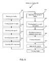
- FIG. 9shows, in flow diagram form, a method of winding and constructing an optical fiber coil assembly according to the present invention.
- the disclosurerelates to a fiber-optic gyroscope system and method of wrapping the pigtails of the fiber-optic gyroscope.
- a pigtailis the end of a strand of optical fiber used to make an optical connection with a circuit element.
- the overall FOG systemis shown, as well as key subsystem components and their interconnections. Pigtail wrapping, tightening, and other integration subsystem details are shown that result in the ability of the FOG assembly to withstand up to 200 g.
- FIG. 1shows a perspective view of one embodiment of a optical fiber coil assembly 100 for use in a fiber optic gyroscope (FOG) assembly, including a bobbin 110 , a rotatable top mount 120 , an optical fiber 125 , an integrated optical circuit (IOC) 170 , and a bridge 190 .
- FOGfiber optic gyroscope
- the bobbin 110is cylindrically shaped with an upper flange 140 and a lower flange 150 disposed on opposite ends of bobbin 110 as shown in FIG. 1 .
- the upper flange 140 and the lower flange 150are disc-shaped, each characterized by two flat, parallel surfaces.
- the bobbin 110is symmetrically disposed about a principal axis AX that is perpendicular to the flat surfaces of the upper flange 140 and the lower flange 150 .
- the bobbin 110is preferably constructed from graphite-epoxy composite with a low thermal coefficient of expansion that closely matches that of the wound fiber 130 . In other embodiments, the bobbin 110 maybe constructed from other materials known in the art to have similar thermal expansion characteristics.
- the bobbin 110forms a circular housing for wound fiber 130 , such that the upper flange 140 and the lower flange 150 overhang wound fiber 130 , as shown in the FIG. 1 .
- Bobbin 110is mechanically affixed to rotatable top mount 120 and bottom mount (not shown).
- Top mount 120is rotatably attached to the bobbin in a way that allows rotation of the top mount 120 about the principle axis AX.
- the optical fiber 125includes a single strand of polarization-maintaining optical fiber, winds about the principal axis of the bobbin 110 , forming a plurality of layers of wound fiber 130 .
- the fiber 125further includes a fiber lead pair 180 .
- Lead pair 180connects to IOC 170 (as described, for example, in related U.S. application Ser. No. 10/120,745 filed Apr. 11, 2002, entitled Method of Aligning Optical Fibers to an IOC), which is connected to rotatable top mount 120 , thus allowing free rotation of IOC 170 .
- IOC 170is an Integrated Optical Circuit, constructed from miniaturized solid-state optical components on a lithium niobate (LiNbO3) substrate, that performs the functions of modulator and splitter.
- the IOC 170may include other suitable semiconductor or dielectric substrates known in the art for supporting the modulator and splitter functions.
- a bridge 190is formed using epoxy such as Norland brand U-V curable epoxy or other similar epoxies known in the art, and serves to attach lead pair 180 to upper flange 140 .
- opposite ends of a strand of optical fiber 125wind in counter-rotating directions about bobbin 110 .
- One of the two emerging ends of optical fiber 125is looped into a reversal 195 as shown in FIG. 1 (and described in more detail herein), and disposed to wrap back upon its opposite end.
- the two ends of optical fiber 125thus wind as a pair back around the bobbin 110 until crossing the upper flange 140 , bridge 190 , and into IOC 170 as fiber lead pair 180 .
- a wavelength light source(not shown—part of the complete FOG assembly) driven at a constant power emits light of constant wavelength. This light propagates through an optical fiber (not shown) that connects to one end of IOC 170 .
- IOC 170includes a waveguide shaped in a Y-configuration, with the two-port side connecting to both ends of optical fiber 125 wound as a coil onto bobbin 110 .
- Light from the light sourceis split within IOC 170 to form two light signals, and travels bi-directionally through wound fiber 130 .
- the light signalsreturn through IOC 170 where they are combined, and pass through a coupler (not shown) that diverts a portion of the combined light to a detecting element (not shown).
- This phase shiftis observed as an interference pattern by the detecting element, and converted into a signal indicative of the rate of rotation, i.e., that contains information about the motion of the system in the plane of wound fiber 130 , and is translated into the gyroscope's output.
- FIG. 2shows a cross sectional view of the optical fiber coil assembly 100 .
- assembly 100further includes a screw 220 , a bottom mount 210 , and an epoxy coating 230 .
- Epoxy coating 230is a conventional high modulus epoxy, e.g., Epoxy Technology's Epotek 330 (although other similar high modulus epoxies known in the art may also be used).
- the epoxy coating 230is applied to the outer portion of each layer of wound fiber 130 as it is wound to secure wound fiber 130 and to prevent slippage.
- an epoxy coating 230may also be applied between the first layer of wound fiber 130 and the bobbin.
- the use of such a high modulus epoxyis important to reducing sensitivity to vibration-induced noise.
- screw 220can be replaced by other suitable fastening mechanisms known in the art, such as epoxy, rivets, etc.
- optical fiber 125is wound around bobbin 110 in a precise manner starting preferably in the middle of its length and wrapping its two ends in opposite directions.
- the fiber 125may be wound around the bobbin 110 starting anywhere between the two ends; however, the winding is substantially symmetrical when the winding starts in the middle of the length of the fiber 125 , and thus is preferable.
- the cross-section of wound fiber 130forms a hexagonal close-packed arrangement as shown in FIG. 2 .
- This packing arrangementis crucial to the resilience and proper functioning of the assembly in that it substantially prevents wound fiber 130 from slipping in a direction parallel to the principal axis AX of bobbin 110 .
- This packing arrangementalso disallows any crossover between ends of wound fiber 130 .
- the thin epoxy coating 230is deposited on each layer of wound fiber 130 and adds farther stability to the packing arrangement.
- the optical fiber 125has a diameter f and is wound until bobbin 110 is fill, except for a distance d on upper flange 140 and lower flange 150 .
- a typical value for fis 165 microns, although other fiber diameters may also be used.
- the value of dcan vary widely depending upon the application, although values of d typically range from 1 to 5 millimeters.
- the optical fiber 125maybe wound onto the bobbin 110 dry, and a vacuum may be employed to draw epoxy throughout the bobbin to secure the wound fiber 130 in place.
- the vacuum and the technique employed to draw epoxy throughout wound fiber 130are well known to those skilled in the art.
- FIG. 3shows the top view of a portion of optical fiber coil assembly 100 , including an epoxy zipper 310 .
- the epoxy zipper 310is formed when epoxy (e.g. Norland's brand U-V curable epoxy, although other similar epoxies known in the art may also be used) is applied between the two optical fiber 125 ends comprising fiber lead pair 180 .
- the epoxy zipper 310may partially or completely encapsulate the two optical fiber 125 ends comprising the lead pair 180 .
- Lead pair 180preferably wraps over the top of bobbin 110 (FIG. 2) and is secured to upper flange 140 by epoxy bridge 190 along the length of the lead pair 180 , toward IOC 170 .
- the epoxy zipper 310is preferably applied between lead pair 180 using the same epoxy as that which composes bridge 190 , e.g. Norland's brand U-V curable epoxy. Epoxy zipper 310 ensures that both ends of optical fiber 125 in lead pair 180 are stationary with respect to one another, as any relative movement between the two ends of fiber 125 may result in the FOG assembly 100 yielding erroneous data.
- FIG. 4is a cross sectional view of lead pair 180 , showing epoxy zipper 310 .
- Epoxy zipper 310secures lead pair 180 together as lead pair 180 emerges above upper flange 140 and connects to IOC 170 .
- the epoxy used to form epoxy zipper 310is preferably applied between lead pair 180 using conventional methods, affording the FOG assembly 100 a more rigid quality and ensuring that the optical fiber 125 ends comprising lead pair 180 undergo no movement relative to one another. It is preferable to keep the optical fiber ends of lead pair 180 as close together as possible.
- the fiber ends of the lead pair 180are adjacent, and the epoxy zipper 310 fills in the regions on either side of the contact point.
- the zippermay further occupy a space between the fiber ends, so that the fiber ends are separated by a gap.
- the zipper 310may completely encapsulate the fiber ends, with or without a gap between the fiber ends.
- Each zipper configurationmay provide different rigidity characteristics between the fiber ends, and different distances between the fiber ends. The particular zipper configuration used is a design choice that depends on the particular application for which the FOG assembly 100 will be incorporated.
- FIG. 5shows a side view of a portion of optical fiber coil assembly 100 of FIG. 1, and includes an upper pigtail 520 and a lower pigtail 510 .
- the optical fiber 125is wrapped onto bobbin 110 outward from the center so that its two opposite ends emerge from wound fibers 130 near the bottom of bobbin 110 , as shown in FIG. 5 .
- Each emerging end of optical fiber 125is referred to herein as a “pigtail.”
- Lower pigtail 510emerges from the lower portion of bobbin 110 and upper pigtail 520 emerges from the underlying layer of wound fiber 130 .
- lower pigtail 510 and upper pigtail 520emerge from bobbin 110 and the two are cut to specific lengths, typically one to three meters in length.
- the total length of optical fiber 125 forming the connections to the two optical-input side of IOC 170determines the eigenfrequency of the FOG assembly and thus trimming the pigtails affects the eigenfrequency of FOG assembly.
- FIG. 6shows a side view of a portion of optical fiber coil assembly 100 illustrating pigtail reversal 195 .
- the lower pigtail 510 emerging near the bottom of bobbin 110is formed into a loop, referred to herein as a reversal 195 .
- the lower pigtail 510falls back upon upper pigtail 520 , and the two pigtails proceed in parallel as a lead pair 180 , until ending in a connection to IOC 170 .
- the reversal 195is spot-tacked to the wound fibers 130 using, for example, Norland brand UV curable epoxy to hold reversal 195 in place.
- Reversal 195is positioned to ensure that the ends of the optical fiber 125 comprising lead pair 180 are exactly equal in length between the point of entrance into IOC 170 and the point at which they are joined after the formation of reversal 195 . This positioning serves to maintain a close proximity between the pigtails and facilitates a precise winding of the pigtails back onto bobbin 110 .
- FIG. 7shows a side view of a portion of optical fiber coil assembly 100 before the final rotation of rotatable top mount 120 and includes wound pigtails 710 .
- IOC 170is mechanically attached to rotatable top mount 120 , which is then attached to upper flange 140 .
- the top mount in FIG. 1is shown to be of a specific form, any suitable mounting fixture that may be rotatably mounted to the bobbin may also be used. At this point the two pigtails wind back onto bobbin 110 as a pair by holding IOC 170 stationary and rotating top mount 120 .
- the two pigtailswind back onto bobbin 110 they form a length of wound pigtails 710 on top of a portion of wound fiber 130 above the top of the loop formed in reversal 195 .
- the completed optical fiber coil assembly 100is a single rigid structure with no element free to vibrate.
- a final coating of epoxye.g. Epotek 330
- IOC 170rests upon rotatable top mount 120 and facilitates the removal of any slack in lead pair 180 .
- lead pair 180is spot-tacked to upper flange 140 with epoxy bridge 190 , and the rotatable top mount 120 is secured via screw 220 to prevent loosening during operation.
- Other methods of securing the top mount known in the arte.g., gluing, soldering, or via alternate mechanisms similar to a screw) may also be used.
- FIG. 9shows method 900 of winding and constructing an optical fiber coil assembly.
- Method 900includes of the following steps:
- Step 910Winding the Bobbin
- optical fiber 125beginning at its center, is wound around bobbin 110 forming a plurality of layers of wound fiber 130 .
- the two opposite ends of optical fiber 125emerge in opposite directions from bobbin 110 as lower pigtail 510 and upper pigtail 520 .
- a thin layer of epoxy coating 230is applied as each layer of wound fiber 130 is formed during the winding.
- Step 920Cutting Pigtails to Length
- lower pigtail 510 and/or upper pigtail 520are cut to specific lengths, typically between one and three meters.
- Step 930Reversing the Pigtails
- lower pigtail 510is wrapped in a loop to form reversal 195 and falls back alongside upper pigtail 520 .
- the reversal 195is spot tacked to temporarily hold it in place. It is important to note that the reversal is formed in the lower pigtail because it is impossible to prevent the two pigtails from crossing over if reversal 195 is formed in the upper pigtail 520 . Degraded FOG performance results if a crossover occurs between the two pigtails.
- Step 935Attaching Pigtail Ends to IOC
- the reversal 195may be adjusted after the pigtails are connected to IOC 170 to ensure that the pigtails are equal in length.
- Step 940Attaching IOC to Top Mount
- IOC 170is fastened to rotatable top mount 120 .
- Step 950Attaching Top Mount to Bobbin
- rotatable top mount 120is fastened to top flange 140 of bobbin 110 .
- IOC 170is now the top piece of the FOG assembly, securely fastened to top mount 120 , which in turn is fastened to bobbin 110 .
- Step 960Winding the Pigtails as a Pair onto Bobbin
- Rotatably mounted IOC 170disallows twists from developing in the pigtails as they wind upward just above the formation of reversal 195 onto bobbin 110 .
- the pigtailsare secured in place with tape and/or a small amount of epoxy.
- Step 970Rotating Spool to Eliminate Excess Slack
- lead pair 180is made taut by the final rotation of top mount 120 , eliminating slack in lead pair 180 between its exit from bobbin 110 and entrance into IOC 170 .
- This stepis facilitated easily by the action of rotatable top mount 120 upon which IOC 170 is fastened.
- Step 980Coating with Epoxy
- the exposed portion of wound fiber 130 on bobbin 110 within upper flange 140 and lower flange 150is coated with a thin layer of epoxy, e.g. Epoxy Technology's Epotek 330.
- Step 990Zippering the Pigtails
- lead pair 180is secured together with an epoxy zipper 310 , e.g. Norland brand U-V curable epoxy, further stabilizing the arrangement and insuring that lower pigtail 510 and upper pigtail 520 comprising lead pair 180 are exposed to identical environments.
- an epoxy zipper 310e.g. Norland brand U-V curable epoxy
- Step 995Forming Bridge
- an amount of epoxye.g. Norland's brand U-V curable epoxy, is applied as a bridge 190 between upper flange 140 and lead pair 180 to lessen the vulnerability of lead pair 180 as it approaches IOC 170 .
Landscapes
- Physics & Mathematics (AREA)
- Engineering & Computer Science (AREA)
- Optics & Photonics (AREA)
- Electromagnetism (AREA)
- Power Engineering (AREA)
- General Physics & Mathematics (AREA)
- Radar, Positioning & Navigation (AREA)
- Remote Sensing (AREA)
- Gyroscopes (AREA)
Abstract
Description
Claims (49)
Priority Applications (3)
| Application Number | Priority Date | Filing Date | Title |
|---|---|---|---|
| US10/003,914US6522826B2 (en) | 2001-05-11 | 2001-11-02 | System and method of winding a fog coil |
| EP02769657AEP1395860A4 (en) | 2001-05-11 | 2002-04-16 | System and method of winding a fog coil |
| PCT/US2002/011975WO2002093217A1 (en) | 2001-05-11 | 2002-04-16 | System and method of winding a fog coil |
Applications Claiming Priority (2)
| Application Number | Priority Date | Filing Date | Title |
|---|---|---|---|
| US29004601P | 2001-05-11 | 2001-05-11 | |
| US10/003,914US6522826B2 (en) | 2001-05-11 | 2001-11-02 | System and method of winding a fog coil |
Publications (2)
| Publication Number | Publication Date |
|---|---|
| US20020167673A1 US20020167673A1 (en) | 2002-11-14 |
| US6522826B2true US6522826B2 (en) | 2003-02-18 |
Family
ID=26672363
Family Applications (1)
| Application Number | Title | Priority Date | Filing Date |
|---|---|---|---|
| US10/003,914Expired - LifetimeUS6522826B2 (en) | 2001-05-11 | 2001-11-02 | System and method of winding a fog coil |
Country Status (3)
| Country | Link |
|---|---|
| US (1) | US6522826B2 (en) |
| EP (1) | EP1395860A4 (en) |
| WO (1) | WO2002093217A1 (en) |
Cited By (30)
| Publication number | Priority date | Publication date | Assignee | Title |
|---|---|---|---|---|
| US20030230664A1 (en)* | 2001-05-15 | 2003-12-18 | Healy Alfred W. | Systems and methods of winding optical fiber |
| US20040218887A1 (en)* | 2003-04-30 | 2004-11-04 | Brown Dennis M. | Spool having a universal flange and method of making same |
| US20040218886A1 (en)* | 2003-04-30 | 2004-11-04 | Brown Dennis M. | Spool with substantially temperature insensitive hub and a method of making same |
| US20060221347A1 (en)* | 2005-03-31 | 2006-10-05 | Honeywell International, Inc. | Adhesive system and method for forming a fiber optic gyroscope sensing coil |
| US20080018902A1 (en)* | 2005-09-13 | 2008-01-24 | The Boeing Company | Embedded interferometric fiber optic gyroscope systems and methods |
| US20080292261A1 (en)* | 2007-05-07 | 2008-11-27 | Kowalczyk Scott C | Fiber optic enclosure with external cable spool |
| US20090060441A1 (en)* | 2007-09-05 | 2009-03-05 | Kowalczyk Scott C | Fiber optic enclosure with tear-away spool |
| US20090074370A1 (en)* | 2007-08-06 | 2009-03-19 | Adc Telecommunications, Inc. | Fiber optic enclosure with internal cable spool |
| US20100074587A1 (en)* | 2008-09-16 | 2010-03-25 | Todd Loeffelholz | Modular fiber optic enclosure with external cable spool |
| US20100322268A1 (en)* | 2009-06-18 | 2010-12-23 | Ipg Photonics Corporation | Dynamic Compensator for Controlling Stresses on Fiber in Fiber Optic Cables |
| US20110024543A1 (en)* | 2009-07-30 | 2011-02-03 | Mark Smrha | Spool for telecommunications cable and method |
| US20110024544A1 (en)* | 2009-07-30 | 2011-02-03 | Mark Smrha | Locking spool for telecommunications cable and method |
| US20110044599A1 (en)* | 2009-07-21 | 2011-02-24 | Adc Telecommunications, Inc. | Rapid universal rack mount enclosure |
| US20110103761A1 (en)* | 2009-09-23 | 2011-05-05 | Adc Telecommunications, Inc. | Fiber Distribution Hub with Internal Cable Spool |
| US8718483B2 (en)* | 2007-10-31 | 2014-05-06 | Bae Systems Australia Ltd | Deployable photonic link and interface module |
| US8720810B2 (en) | 2011-02-11 | 2014-05-13 | Adc Telecommunications, Inc. | Spool for telecommunications cable and method |
| US8837940B2 (en) | 2010-04-14 | 2014-09-16 | Adc Telecommunications, Inc. | Methods and systems for distributing fiber optic telecommunication services to local areas and for supporting distributed antenna systems |
| USRE45153E1 (en) | 2007-01-13 | 2014-09-23 | Adc Telecommunications, Inc. | Fiber optic cable distribution box |
| US20150093088A1 (en)* | 2013-09-30 | 2015-04-02 | Optema Technology Limited | Fiber Optic Terminal Assemblies |
| US9126802B2 (en) | 2012-04-30 | 2015-09-08 | Adc Telecommunications, Inc. | Payout spool with automatic cable disconnect/reconnect |
| US9188760B2 (en) | 2011-12-22 | 2015-11-17 | Adc Telecommunications, Inc. | Mini rapid delivery spool |
| US9261663B2 (en) | 2010-06-18 | 2016-02-16 | Adc Communications (Shanghai) Co., Ltd. | Fiber optic distribution terminal and method of deploying fiber distribution cable |
| US9500831B2 (en) | 2012-04-30 | 2016-11-22 | Commscope Technologies Llc | Cable payout cassette with single layer cable storage area |
| US9722407B2 (en) | 2012-04-30 | 2017-08-01 | Commscope Technologies Llc | Guided cable storage assembly with switchbacks |
| US9908742B2 (en) | 2012-04-30 | 2018-03-06 | Commscope Technologies Llc | Cable storage spool with center feed |
| US9995898B2 (en) | 2010-06-23 | 2018-06-12 | Commscope Technologies Llc | Telecommunications assembly |
| US10371914B2 (en) | 2011-06-24 | 2019-08-06 | Commscope Technologies Llc | Fiber termination enclosure with modular plate assemblies |
| US10545305B2 (en) | 2012-12-19 | 2020-01-28 | CommScope Connectivity Belgium BVBA | Distribution device with incrementally added splitters |
| US11183865B2 (en)* | 2019-01-07 | 2021-11-23 | Hades-Gaming Corporation | Wireless charging mousepad structure and processes |
| US20240159984A1 (en)* | 2022-11-14 | 2024-05-16 | Jiangsu SUMEC Electromechanical Co., Ltd. | Optical cable assembly and optical cable testing method |
Families Citing this family (3)
| Publication number | Priority date | Publication date | Assignee | Title |
|---|---|---|---|---|
| US7369247B2 (en)* | 2005-11-15 | 2008-05-06 | Honeywell International, Inc. | Sensing coil assembly and method for attaching a sensing coil in a fiber optic gyroscope |
| US10433717B1 (en)* | 2018-06-28 | 2019-10-08 | Meditrina, Inc. | Endoscope having size-adjustable working channel |
| CN118072458B (en)* | 2024-04-01 | 2024-09-10 | 河北骁盾科技有限公司 | Distributed optical fiber line type temperature-sensing fire disaster detector |
Citations (10)
| Publication number | Priority date | Publication date | Assignee | Title |
|---|---|---|---|---|
| US5168539A (en)* | 1990-11-28 | 1992-12-01 | Matsushita Electric Industrial Co., Ltd. | Fiber-optic coil and method of manufacturing same |
| US5181270A (en)* | 1991-08-09 | 1993-01-19 | Hughes Aircraft Company | Optical fiber canister |
| US5220632A (en) | 1992-06-24 | 1993-06-15 | Hughes Aircraft Company | Preparation of an optical fiber canister |
| US5245687A (en)* | 1991-07-01 | 1993-09-14 | Japan Aviation Electronics Industry Limited | Optical fiber coil unit for a fiber optic gyro |
| US5481358A (en) | 1993-12-27 | 1996-01-02 | Andrew Corporation | Coil mounting arrangement for fiber optic gyroscope using a gel loaded with particles |
| US5923807A (en) | 1997-03-06 | 1999-07-13 | Lucent Technologies Inc. | Storage apparatus for optical fiber |
| US5973783A (en) | 1998-07-31 | 1999-10-26 | Litton Systems, Inc. | Fiber optic gyroscope coil lead dressing and method for forming the same |
| US6038025A (en) | 1998-04-09 | 2000-03-14 | Honeywell Inc. | Method for manufacturing of fiberoptic gyroscope by providing a flexible connector connected to the coil and remaining gyroscope elements |
| US6137940A (en) | 1997-11-20 | 2000-10-24 | Alcatel | Reel of optical fiber |
| US6349166B1 (en)* | 1998-12-28 | 2002-02-19 | Honeywell International Inc. | Adhesive system for a fiber optic gyroscope sensing coil |
Family Cites Families (3)
| Publication number | Priority date | Publication date | Assignee | Title |
|---|---|---|---|---|
| GB2265457B (en)* | 1992-03-28 | 1995-10-11 | British Aerospace | A fibre optic gyro |
| US5841932A (en)* | 1996-06-21 | 1998-11-24 | Honeywell Inc. | Optical fiber coil and method of winding |
| US5781301A (en)* | 1997-03-31 | 1998-07-14 | The United States Of America As Represented By The Secretary Of The Army | Thermally symmetric, crossover-free fiber optic sensor coils and method for winding them |
- 2001
- 2001-11-02USUS10/003,914patent/US6522826B2/ennot_activeExpired - Lifetime
- 2002
- 2002-04-16WOPCT/US2002/011975patent/WO2002093217A1/ennot_activeApplication Discontinuation
- 2002-04-16EPEP02769657Apatent/EP1395860A4/ennot_activeWithdrawn
Patent Citations (10)
| Publication number | Priority date | Publication date | Assignee | Title |
|---|---|---|---|---|
| US5168539A (en)* | 1990-11-28 | 1992-12-01 | Matsushita Electric Industrial Co., Ltd. | Fiber-optic coil and method of manufacturing same |
| US5245687A (en)* | 1991-07-01 | 1993-09-14 | Japan Aviation Electronics Industry Limited | Optical fiber coil unit for a fiber optic gyro |
| US5181270A (en)* | 1991-08-09 | 1993-01-19 | Hughes Aircraft Company | Optical fiber canister |
| US5220632A (en) | 1992-06-24 | 1993-06-15 | Hughes Aircraft Company | Preparation of an optical fiber canister |
| US5481358A (en) | 1993-12-27 | 1996-01-02 | Andrew Corporation | Coil mounting arrangement for fiber optic gyroscope using a gel loaded with particles |
| US5923807A (en) | 1997-03-06 | 1999-07-13 | Lucent Technologies Inc. | Storage apparatus for optical fiber |
| US6137940A (en) | 1997-11-20 | 2000-10-24 | Alcatel | Reel of optical fiber |
| US6038025A (en) | 1998-04-09 | 2000-03-14 | Honeywell Inc. | Method for manufacturing of fiberoptic gyroscope by providing a flexible connector connected to the coil and remaining gyroscope elements |
| US5973783A (en) | 1998-07-31 | 1999-10-26 | Litton Systems, Inc. | Fiber optic gyroscope coil lead dressing and method for forming the same |
| US6349166B1 (en)* | 1998-12-28 | 2002-02-19 | Honeywell International Inc. | Adhesive system for a fiber optic gyroscope sensing coil |
Cited By (109)
| Publication number | Priority date | Publication date | Assignee | Title |
|---|---|---|---|---|
| US20030230664A1 (en)* | 2001-05-15 | 2003-12-18 | Healy Alfred W. | Systems and methods of winding optical fiber |
| US6685128B2 (en)* | 2001-05-15 | 2004-02-03 | Northrop Grumman Corporation | Systems and methods of winding optical fiber |
| US20040218887A1 (en)* | 2003-04-30 | 2004-11-04 | Brown Dennis M. | Spool having a universal flange and method of making same |
| US20040218886A1 (en)* | 2003-04-30 | 2004-11-04 | Brown Dennis M. | Spool with substantially temperature insensitive hub and a method of making same |
| US7116885B2 (en)* | 2003-04-30 | 2006-10-03 | Corning Incorporated | Spool having a universal flange and method of making same |
| US20060221347A1 (en)* | 2005-03-31 | 2006-10-05 | Honeywell International, Inc. | Adhesive system and method for forming a fiber optic gyroscope sensing coil |
| US7295323B2 (en)* | 2005-03-31 | 2007-11-13 | Honeywell International Inc. | Adhesive system and method for forming a fiber optic gyroscope sensing coil |
| US20080018902A1 (en)* | 2005-09-13 | 2008-01-24 | The Boeing Company | Embedded interferometric fiber optic gyroscope systems and methods |
| US7352471B2 (en)* | 2005-09-13 | 2008-04-01 | The Boeing Company | Embedded interferometric fiber optic gyroscope systems and methods |
| USRE48063E1 (en) | 2007-01-13 | 2020-06-23 | Commscope Technologies Llc | Fiber optic cable distribution box |
| USRE46255E1 (en) | 2007-01-13 | 2016-12-27 | Commscope Technologies Llc | Fiber optic cable distribution box |
| USRE49385E1 (en) | 2007-01-13 | 2023-01-24 | Commscope Technologies Llc | Fiber optic cable distribution box |
| USRE45153E1 (en) | 2007-01-13 | 2014-09-23 | Adc Telecommunications, Inc. | Fiber optic cable distribution box |
| US11009671B2 (en)* | 2007-05-07 | 2021-05-18 | Commscope Technologies Llc | Fiber optic assembly with cable storage arrangement |
| US12235506B2 (en) | 2007-05-07 | 2025-02-25 | Commscope Technologies Llc | Fiber optic enclosure with external cable spool |
| US20100247051A1 (en)* | 2007-05-07 | 2010-09-30 | Adc Telecommuncations, Inc. | Fiber optic enclosure with external cable spool |
| US10788642B2 (en) | 2007-05-07 | 2020-09-29 | Commscope Technologies Llc | Fiber optic assembly with cable storage arrangement |
| US20080292261A1 (en)* | 2007-05-07 | 2008-11-27 | Kowalczyk Scott C | Fiber optic enclosure with external cable spool |
| US8131126B2 (en) | 2007-05-07 | 2012-03-06 | Adc Telecommunications, Inc. | Fiber optic enclosure with external cable spool |
| US10627592B2 (en) | 2007-05-07 | 2020-04-21 | Commscope Technologies Llc | Fiber optic assembly with cable spool |
| US20170235079A1 (en)* | 2007-05-07 | 2017-08-17 | Commscope Technologies Llc | Fiber optic enclosure with external cable spool |
| US9535227B2 (en) | 2007-05-07 | 2017-01-03 | Commscope Technologies Llc | Fiber optic cable spool assembly |
| US7715679B2 (en) | 2007-05-07 | 2010-05-11 | Adc Telecommunications, Inc. | Fiber optic enclosure with external cable spool |
| US9057860B2 (en) | 2007-05-07 | 2015-06-16 | Adc Telecommunications, Inc. | Fiber optic enclosure with external cable spool |
| US20210302682A1 (en)* | 2007-05-07 | 2021-09-30 | Commscope Technologies Llc | Fiber optic enclosure with external cable spool |
| US8380035B2 (en) | 2007-05-07 | 2013-02-19 | Adc Telecommunications, Inc. | Fiber optic enclosure with external cable spool |
| US10712518B2 (en) | 2007-08-06 | 2020-07-14 | Commscope Technologies Llc | Fiber optic enclosure with lockable internal cable spool |
| US9606319B2 (en) | 2007-08-06 | 2017-03-28 | Commscope Technologies Llc | Fiber optic enclosure with internal cable spool |
| US8189984B2 (en) | 2007-08-06 | 2012-05-29 | Adc Telecommunications, Inc. | Fiber optic enclosure with internal cable spool |
| US7894701B2 (en) | 2007-08-06 | 2011-02-22 | Adc Telecommunications, Inc. | Fiber optic enclosure with internal cable spool |
| US11573390B2 (en) | 2007-08-06 | 2023-02-07 | Commscope Technologies Llc | Fiber optic enclosure with internal cable spool |
| US20100310224A1 (en)* | 2007-08-06 | 2010-12-09 | Adc Telecommunications, Inc. | Fiber optic enclosure with internal cable spool |
| US10606017B2 (en) | 2007-08-06 | 2020-03-31 | Commscope Technologies Llc | Fiber optic payout assembly including cable spool |
| US10606015B2 (en) | 2007-08-06 | 2020-03-31 | Commscope Technologies Llc | Fiber optic payout assembly including cable spool |
| US20110158599A1 (en)* | 2007-08-06 | 2011-06-30 | Adc Telecommunications, Inc. | Fiber optic enclosure with internal cable spool |
| US10495836B2 (en) | 2007-08-06 | 2019-12-03 | Commscope Technologies Llc | Fiber optic payout assembly including cable spool |
| US8494333B2 (en) | 2007-08-06 | 2013-07-23 | Adc Telecommunications, Inc. | Dispensing cable from an internal cable spool of a fiber optic enclosure |
| US12019301B2 (en) | 2007-08-06 | 2024-06-25 | Commscope Technologies Llc | Fiber optic enclosure with internal cable spool |
| US8705929B2 (en) | 2007-08-06 | 2014-04-22 | Adc Telecommunications, Inc. | Fiber optic enclosure with internal cable spool |
| US20090074370A1 (en)* | 2007-08-06 | 2009-03-19 | Adc Telecommunications, Inc. | Fiber optic enclosure with internal cable spool |
| US10895705B2 (en) | 2007-08-06 | 2021-01-19 | Commscope Technologies Llc | Fiber optic enclosure with internal cable spool |
| US7756379B2 (en) | 2007-08-06 | 2010-07-13 | Adc Telecommunications, Inc. | Fiber optic enclosure with internal cable spool |
| US10996417B2 (en) | 2007-08-06 | 2021-05-04 | Commscope Technologies Llc | Fiber optic enclosure with internal cable spool and movable cover |
| US10247897B2 (en) | 2007-08-06 | 2019-04-02 | Commscope Technologies Llc | Fiber optic enclosure with internal cable spool |
| US10996418B2 (en) | 2007-08-06 | 2021-05-04 | Commscope Technologies Llc | Connecting subscribers to a fiber optic network using a cable spool |
| US8891931B2 (en) | 2007-08-06 | 2014-11-18 | Adc Telecommunications, Inc. | Fiber optic enclosure with internal cable spool |
| US12253734B2 (en) | 2007-08-06 | 2025-03-18 | Commscope Technologies Llc | Fiber optic enclosure with internal cable spool |
| US10234648B2 (en) | 2007-08-06 | 2019-03-19 | Commscope Technologies Llc | Fiber optic enclosure with internal cable spool |
| US9261666B2 (en) | 2007-08-06 | 2016-02-16 | Commscope Technologies Llc | Fiber optic enclosure with internal cable spool |
| US8774588B2 (en) | 2007-09-05 | 2014-07-08 | Adc Telecommunications, Inc. | Fiber optic enclosure with tear-away spool |
| US9229185B2 (en) | 2007-09-05 | 2016-01-05 | Commscope Technologies Llc | Fiber optic enclosure with tear-away spool |
| US20090060441A1 (en)* | 2007-09-05 | 2009-03-05 | Kowalczyk Scott C | Fiber optic enclosure with tear-away spool |
| US20110091180A1 (en)* | 2007-09-05 | 2011-04-21 | Adc Telecommunications, Inc. | Fiber optic enclosure with tear-away spool |
| US9563032B2 (en) | 2007-09-05 | 2017-02-07 | Commscope Technologies Llc | Fiber optic enclosure with tear-away spool |
| US8494334B2 (en) | 2007-09-05 | 2013-07-23 | Adc Telecommunications, Inc. | Fiber optic enclosure with tear-away spool |
| US7869682B2 (en) | 2007-09-05 | 2011-01-11 | Adc Telecommunications, Inc. | Fiber optic enclosure with tear-away spool |
| US8229267B2 (en) | 2007-09-05 | 2012-07-24 | Adc Telecommunications, Inc. | Fiber optic enclosure with tear-away spool |
| US8718483B2 (en)* | 2007-10-31 | 2014-05-06 | Bae Systems Australia Ltd | Deployable photonic link and interface module |
| US20100074587A1 (en)* | 2008-09-16 | 2010-03-25 | Todd Loeffelholz | Modular fiber optic enclosure with external cable spool |
| US8265447B2 (en) | 2008-09-16 | 2012-09-11 | Adc Telecommunications, Inc. | Modular fiber optic enclosure with external cable spool |
| US20100322268A1 (en)* | 2009-06-18 | 2010-12-23 | Ipg Photonics Corporation | Dynamic Compensator for Controlling Stresses on Fiber in Fiber Optic Cables |
| US7876805B2 (en)* | 2009-06-18 | 2011-01-25 | Valentin P Gapontsev | Dynamic compensator for controlling stresses on fiber in fiber optic cables |
| US20110044599A1 (en)* | 2009-07-21 | 2011-02-24 | Adc Telecommunications, Inc. | Rapid universal rack mount enclosure |
| US12265274B2 (en) | 2009-07-21 | 2025-04-01 | Commscope Technologies Llc | Rapid universal rack mount enclosure |
| US9885846B2 (en) | 2009-07-21 | 2018-02-06 | Commscope Technologies Llc | Rapid universal rack mount enclosure |
| US11287592B2 (en) | 2009-07-21 | 2022-03-29 | Commscope Technologies Llc | Rapid universal rack mount enclosure |
| US9448377B2 (en) | 2009-07-21 | 2016-09-20 | Commscope Technologies Llc | Rapid universal rack mount enclosure |
| US8422847B2 (en) | 2009-07-21 | 2013-04-16 | Adc Telecommunications, Inc. | Rapid universal rack mount enclosure |
| US11809008B2 (en) | 2009-07-21 | 2023-11-07 | Commscope Technologies Llc | Rapid universal rack mount enclosure |
| US8798429B2 (en) | 2009-07-21 | 2014-08-05 | Adc Telecommunications, Inc. | Rapid universal rack mount enclosure |
| US10768386B2 (en) | 2009-07-21 | 2020-09-08 | Commscope Technologies Llc | Rapid universal rack mount enclosure |
| US20110024544A1 (en)* | 2009-07-30 | 2011-02-03 | Mark Smrha | Locking spool for telecommunications cable and method |
| US8474742B2 (en) | 2009-07-30 | 2013-07-02 | Adc Telecommunications, Inc. | Spool for telecommunications cable and method |
| US8238707B2 (en)* | 2009-07-30 | 2012-08-07 | Adc Telecommunications, Inc. | Locking spool for telecommunications cable and method |
| US20110024543A1 (en)* | 2009-07-30 | 2011-02-03 | Mark Smrha | Spool for telecommunications cable and method |
| US20110103761A1 (en)* | 2009-09-23 | 2011-05-05 | Adc Telecommunications, Inc. | Fiber Distribution Hub with Internal Cable Spool |
| US8428419B2 (en) | 2009-09-23 | 2013-04-23 | Adc Telecommunications, Inc. | Fiber distribution hub with internal cable spool |
| US9414137B2 (en) | 2010-04-14 | 2016-08-09 | Commscope Technologies Llc | Methods and systems for distributing fiber optic telecommunication services to local areas and for supporting distributed antenna systems |
| US10819444B2 (en) | 2010-04-14 | 2020-10-27 | Commscope Technologies Llc | Methods and systems for distributing fiber optic telecommunication services to local areas and for supporting distributed antenna systems |
| US8837940B2 (en) | 2010-04-14 | 2014-09-16 | Adc Telecommunications, Inc. | Methods and systems for distributing fiber optic telecommunication services to local areas and for supporting distributed antenna systems |
| US9563031B2 (en) | 2010-06-18 | 2017-02-07 | Adc Telecommunications (Shanghai) Distribution Co., Ltd. | Fiber optic enclosure with internal cable spool |
| US9261663B2 (en) | 2010-06-18 | 2016-02-16 | Adc Communications (Shanghai) Co., Ltd. | Fiber optic distribution terminal and method of deploying fiber distribution cable |
| US10884211B2 (en) | 2010-06-23 | 2021-01-05 | Commscope Technologies Llc | Telecommunications assembly |
| US9995898B2 (en) | 2010-06-23 | 2018-06-12 | Commscope Technologies Llc | Telecommunications assembly |
| US12235504B2 (en) | 2010-06-23 | 2025-02-25 | Commscope Technologies Llc | Telecommunications assembly |
| US11789226B2 (en) | 2010-06-23 | 2023-10-17 | Commscope Technologies Llc | Telecommunications assembly |
| US11402595B2 (en) | 2010-06-23 | 2022-08-02 | Commscope Technologies Llc | Telecommunications assembly |
| US10627593B2 (en) | 2010-06-23 | 2020-04-21 | Commscope Technologies Llc | Telecommunications assembly |
| US10268014B2 (en) | 2010-06-23 | 2019-04-23 | Commscope Technologies Llc | Telecommunications assembly |
| US10126516B1 (en) | 2010-06-23 | 2018-11-13 | Commscope Technologies Llc | Telecommunications assembly |
| US8720810B2 (en) | 2011-02-11 | 2014-05-13 | Adc Telecommunications, Inc. | Spool for telecommunications cable and method |
| US11327262B2 (en) | 2011-06-24 | 2022-05-10 | Commscope Technologies Llc | Fiber termination enclosure with modular plate assemblies |
| US10502916B2 (en) | 2011-06-24 | 2019-12-10 | Commscope Technologies Llc | Fiber termination enclosure with modular plate assemblies |
| US11988883B2 (en) | 2011-06-24 | 2024-05-21 | Commscope Technologies Llc | Fiber termination enclosure with modular plate assemblies |
| US11624884B2 (en) | 2011-06-24 | 2023-04-11 | Commscope Technologies Llc | Fiber termination enclosure with modular plate assemblies |
| US10935744B2 (en) | 2011-06-24 | 2021-03-02 | Commscope Technologies Llc | Fiber termination enclosure with modular plate assemblies |
| US10371914B2 (en) | 2011-06-24 | 2019-08-06 | Commscope Technologies Llc | Fiber termination enclosure with modular plate assemblies |
| US9523834B2 (en) | 2011-12-22 | 2016-12-20 | Commscope Technologies Llc | Fiber optic enclosure |
| US9188760B2 (en) | 2011-12-22 | 2015-11-17 | Adc Telecommunications, Inc. | Mini rapid delivery spool |
| US9722407B2 (en) | 2012-04-30 | 2017-08-01 | Commscope Technologies Llc | Guided cable storage assembly with switchbacks |
| US9908742B2 (en) | 2012-04-30 | 2018-03-06 | Commscope Technologies Llc | Cable storage spool with center feed |
| US9939600B2 (en) | 2012-04-30 | 2018-04-10 | Commscope Technologies Llc | Optical fiber disconnect/reconnect apparatus |
| US9500831B2 (en) | 2012-04-30 | 2016-11-22 | Commscope Technologies Llc | Cable payout cassette with single layer cable storage area |
| US9126802B2 (en) | 2012-04-30 | 2015-09-08 | Adc Telecommunications, Inc. | Payout spool with automatic cable disconnect/reconnect |
| US10625978B2 (en)* | 2012-04-30 | 2020-04-21 | Commscope Technologies Llc | Cable storage spool with center feed |
| US10545305B2 (en) | 2012-12-19 | 2020-01-28 | CommScope Connectivity Belgium BVBA | Distribution device with incrementally added splitters |
| US20150093088A1 (en)* | 2013-09-30 | 2015-04-02 | Optema Technology Limited | Fiber Optic Terminal Assemblies |
| US11183865B2 (en)* | 2019-01-07 | 2021-11-23 | Hades-Gaming Corporation | Wireless charging mousepad structure and processes |
| US20240159984A1 (en)* | 2022-11-14 | 2024-05-16 | Jiangsu SUMEC Electromechanical Co., Ltd. | Optical cable assembly and optical cable testing method |
Also Published As
| Publication number | Publication date |
|---|---|
| EP1395860A1 (en) | 2004-03-10 |
| WO2002093217A1 (en) | 2002-11-21 |
| EP1395860A4 (en) | 2006-08-09 |
| US20020167673A1 (en) | 2002-11-14 |
Similar Documents
| Publication | Publication Date | Title |
|---|---|---|
| US6522826B2 (en) | System and method of winding a fog coil | |
| JP5424805B2 (en) | Two-wind fiber optic housing for fiber optic gyroscope | |
| US5973783A (en) | Fiber optic gyroscope coil lead dressing and method for forming the same | |
| US5767509A (en) | Fiber optic sensor coil including buffer regions | |
| CN104380042B (en) | Sensing coil for fiber optic gyroscopes and manufacturing method for same | |
| US7477806B2 (en) | Crossover-free fiber optic coil sensor and winding method | |
| JP2939412B2 (en) | Optical fiber coil and method for winding optical fiber around sensor spool | |
| JP5651463B2 (en) | Sensing coil for optical fiber gyro and manufacturing method thereof | |
| EP0833128A2 (en) | Assembly jig for optical fiber gyro and method of assembling optical fiber gyro | |
| JP3679602B2 (en) | Optical fiber array | |
| JPH06129864A (en) | Polarizer for optical fiber gyro | |
| JP2006509221A (en) | Facilitating reduction of one or more strain gradients in an optical fiber winding by a buffer layer | |
| JP2849736B2 (en) | Fiber optic gyro | |
| US7369246B2 (en) | Method for winding sensing coils and sensing coil for fiber optic gyroscopes | |
| JPH01299413A (en) | Rotational angular velocity sensor | |
| JPS60133315A (en) | Fiber coil for optical fiber gyroscope | |
| US6222633B1 (en) | Gyros having an optical fiber loop and a dual phase-conjugate mirror | |
| JPS63290913A (en) | Manufacturing method of optical fiber gyrometer | |
| JPH04122318U (en) | Optical fiber gyro device and true north measurement using it | |
| JPH0752258B2 (en) | Optical fiber phase modulator | |
| JP2001227957A (en) | Fiber optic gyroscope | |
| JPH01305311A (en) | Optical interference gyrometer | |
| IL148688A (en) | Method of attaching a pair of fiber optic leads to a fiber optic gyroscope sensing coil | |
| JPH04244914A (en) | Polarizer for optical fiber gyro device | |
| JPH1144544A (en) | Phase modulation optical fiber gyro |
Legal Events
| Date | Code | Title | Description |
|---|---|---|---|
| AS | Assignment | Owner name:FIBERSENSE TECHNOLOGY CORPORATION, MASSACHUSETTS Free format text:ASSIGNMENT OF ASSIGNORS INTEREST;ASSIGNOR:GREGORY, PETER;REEL/FRAME:012357/0773 Effective date:20011101 | |
| STCF | Information on status: patent grant | Free format text:PATENTED CASE | |
| FEPP | Fee payment procedure | Free format text:PAYOR NUMBER ASSIGNED (ORIGINAL EVENT CODE: ASPN); ENTITY STATUS OF PATENT OWNER: LARGE ENTITY | |
| FPAY | Fee payment | Year of fee payment:4 | |
| AS | Assignment | Owner name:LITTON SYSTEMS, INC., CALIFORNIA Free format text:MERGER;ASSIGNOR:FIBERSENSE TECHNOLOGY CORPORATION;REEL/FRAME:018148/0543 Effective date:20060620 | |
| FEPP | Fee payment procedure | Free format text:PAYER NUMBER DE-ASSIGNED (ORIGINAL EVENT CODE: RMPN); ENTITY STATUS OF PATENT OWNER: LARGE ENTITY Free format text:PAYOR NUMBER ASSIGNED (ORIGINAL EVENT CODE: ASPN); ENTITY STATUS OF PATENT OWNER: LARGE ENTITY | |
| FEPP | Fee payment procedure | Free format text:PAT HOLDER NO LONGER CLAIMS SMALL ENTITY STATUS, ENTITY STATUS SET TO UNDISCOUNTED (ORIGINAL EVENT CODE: STOL); ENTITY STATUS OF PATENT OWNER: LARGE ENTITY Free format text:PAYOR NUMBER ASSIGNED (ORIGINAL EVENT CODE: ASPN); ENTITY STATUS OF PATENT OWNER: LARGE ENTITY Free format text:PAYER NUMBER DE-ASSIGNED (ORIGINAL EVENT CODE: RMPN); ENTITY STATUS OF PATENT OWNER: LARGE ENTITY | |
| FPAY | Fee payment | Year of fee payment:8 | |
| AS | Assignment | Owner name:NORTHROP GRUMMAN SYSTEMS CORPORATION, CALIFORNIA Free format text:ASSIGNMENT OF ASSIGNORS INTEREST;ASSIGNOR:NORTHROP GRUMMAN CORPORATION;REEL/FRAME:025597/0505 Effective date:20110104 | |
| FPAY | Fee payment | Year of fee payment:12 |